the mebradrain system - zlepšovanie vlastností … · the mebradrain ® system vertical ... the...
TRANSCRIPT
1
Contents General Operation Application Requirements Installation Calculation Labtest Specs References
Zuider IJdijk 58 1095 KN AmsterdamPostbus 94900 1090 GX AmsterdamTel: +31-20-6651614Fax: +31-20-6941457Web: www.geotechnics.nl
The Mebradrain® SystemVertical drainage
N.G. Cortlever

2
Contents General Operation Application Requirements Installation Calculation Labtest S pecs References
General 3
Operation Principle 4Mebradrain 5Sand drain 6Filter Fabric 6Quality Control 7
Application Consolidation 8Stability 9Dewatering 11Preloading 11 Surcharge 12
Vacuum Consolidation 12Deep Well 15
Environmental Landfills 15Sludge Depots 16Soil Cleaning 16Degassing 17
Requirements Drain Strength 18Filter Strength 18Discharge Capacity 19Permeability Filter 19Pore Size Filter 20Summary 20
Installation General 21Pushing 21Vibration 22Offshore 23Redrilling 23
Calculation 24
Lab Tests Compression Test 27Discharge test 28Pore Size Filter 28Permittivitty Filter 29Chemical Resistance 29
Specifications General 29Prefab Drains 30
Reference Projects
Papers 32
Contents

3
Contents General Operation Application Requirements Installation Calculation Labtest Specs References
The Mebradrain® System
1. GENERAL
Prefab vertical drains were first used in Sweden in1937. These drains were manufactured incardboard, the so-called cardboard wick. Approx.10 years earlier sanddrains were developed inCalifornia to expedite consolidation. Especiallyin the Netherlands sanddrains were applied on alarge scale since 1950. Dutch soil mainly consistsof clay and peat layers which can sometimesreach great depths. A sandy surcharge was oftenplaced on top of compressible subsoil in thoseplaces where an industrial or residential estate orinfrastructure had to be developed. Settlements inthe subsoil were expedited by using sanddrains.The synthetic drain was introduced in 1972 for abuilding pit at the Hemweg power station inAmsterdam. Its development was then accelerated.Synthetic drains are superior to sanddrains becauseof their flexibility and better filtration, and theybecame a formidable competitor. Nowadays,sanddrains are hardly ever used.Because of the great demand for a high-qualitysynthetic drain, Geotechnics Holland by developedthe Mebradrain in 1978. Mebradrain has sincegrown into the vertical drain which is used mostoften in the world. In the meantime, more than500,000,000 m of Mebradrain have been appliedin 39 different countries.This paper covers many aspects of the syntheticdrain, from application to quality control, fromdesign methodology to laboratory tests.
Clay and Peat
Sand
General
4
Contents General Operation Application Requirements Installation Calculation Labtest S pecs References
2. WERKING
2.1 Principle
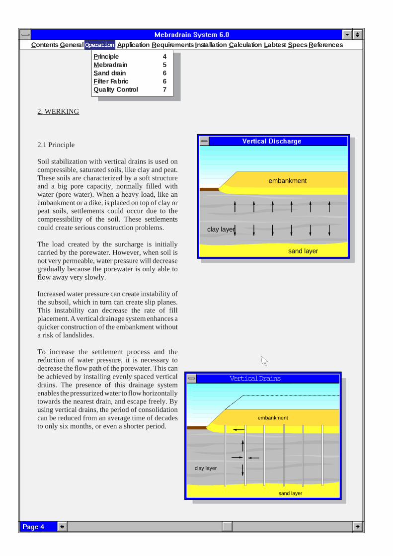
Soil stabilization with vertical drains is used oncompressible, saturated soils, like clay and peat.These soils are characterized by a soft structureand a big pore capacity, normally filled withwater (pore water). When a heavy load, like anembankment or a dike, is placed on top of clay orpeat soils, settlements could occur due to thecompressibility of the soil. These settlementscould create serious construction problems.
The load created by the surcharge is initiallycarried by the porewater. However, when soil isnot very permeable, water pressure will decreasegradually because the porewater is only able toflow away very slowly.
Increased water pressure can create instability ofthe subsoil, which in turn can create slip planes.This instability can decrease the rate of fillplacement. A vertical drainage system enhances aquicker construction of the embankment withouta risk of landslides.
To increase the settlement process and thereduction of water pressure, it is necessary todecrease the flow path of the porewater. This canbe achieved by installing evenly spaced verticaldrains. The presence of this drainage systemenables the pressurized water to flow horizontallytowards the nearest drain, and escape freely. Byusing vertical drains, the period of consolidationcan be reduced from an average time of decadesto only six months, or even a shorter period.
OOOOOperationperationperationperationperation
Principle 4Mebradrain 5S and drain 6F ilter Fabric 6Quality Control 7
clay layer
sand layer
embankment
clay layer
sand layer
embankment
Vertical Drains

5
Contents General Operation Application Requirements Installation Calculation Labtest Specs References
req u ired sett lem en t
n o d ra in s
vert ica l d ra in s
vertica l d ra in s w ith p re load
en d p re load p eriod
By applying surcharghe or a vacuum system, it ispossible to accelerate consolidation even further
Adjoining graph explains this method. The uppercurve shows the settlement of the load withoutusing vertical drainage. The blue curve shows theeffect of vertical drainage application and the redcurve shows the progress of settlement when atemporary load is removed after reaching thedesired settlement.
Soil improvement by means of vertical drains hasbeen used in many civil engineering projects.Some of the applications are shown in:
* Construction of embankments for roads,railways, airports and dikes
* Land reclamation* Construction of ports* Residential and industrial areas* Preloading of storage and landfill depots.
2.2 MEBRADRAIN
Mebradrain® consists of a prefabricated stripwhich is very suitable for water transportation.The flexible core is manufactured of a highqualitypolypropylene. Both sides have grooves, throughwhich water can flow unimpeded. The core iswrapped in a strong and durable geotextile filterfabric with excellent filtration properties, allowingfree access of porewater into the drain. At thesame time, this filter prevents piping of fines fromadjacent soils without clogging.
The drains is manufactured in a width of 100 mm,a size accepted as standard worldwide.Mebradrain° is available in 3 types:
MD88 / 7007
which is a drain type with high discharge capacity,suitable for depths upto 25 meters;
MD88M
is a drain suitable for depth up to 50 m.
MD7007MD7007MD7007MD7007MD7007
OOOOOperationperationperationperationperation

6
Contents General Operation Application Requirements Installation Calculation Labtest S pecs References
Both types are available with a filter that can beadjusted to specific soil conditions. Mebradrainhas grown into one of the most used drainagesystems in the world, and the multiple applicationsof Mebradrain in lots of projects throughout theworld proves that customers have confidence inour product. By the end of 2002, a total of over500 million meters of Mebradrain had beeninstalled worldwide.
Advantages of the Mebradrain system:
* The least possible disturbance of soil layers* A guaranteed water discharge* The possibility of adapting the core and the
filter to specific soil conditions* The high installation rate; 4,000 to 8,000
m' per day/unit* The adaptable spacing, thus enabling a
very short period of consolidation* No water requirement for installation* Drain installation possible to depths
exceeding 50 meters* Easy control of installation.
2.3 Sanddrains
The core of the Mebradrain guarantees a highervertical discharge capacity than a sanddrain witha diameter of 300 mm. Assuming that theequivalent diameter of a 100 mm synthetic drainamounts to 65 mm, a comparison between bothdrain distances can be made by using the Barronformula. Adjoining graph shows that, theoretically,approx. twice as many drains should have to beused in order to result into a similar progress insettlement. Because of the considerably lowerprice of synthetic drains, this system is ultimatelymuch more cost-effective than sanddrains.
2.4 Filter Fabric
The filter jacket has an important function. Itconsists of thermically bonded polypropylenefabric of a random texture. 0 1 2 3 4
5
4
3
2
1
0
Mebradrain distance
300
mm
San
ddra
in d
ista
nce
OOOOOperationperationperationperationperation
7
Contents General Operation Application Requirements Installation Calculation Labtest Specs References
discharge channel
waterflowwith veryfine p atic les
Me bradra in core
Typarfilter fabric
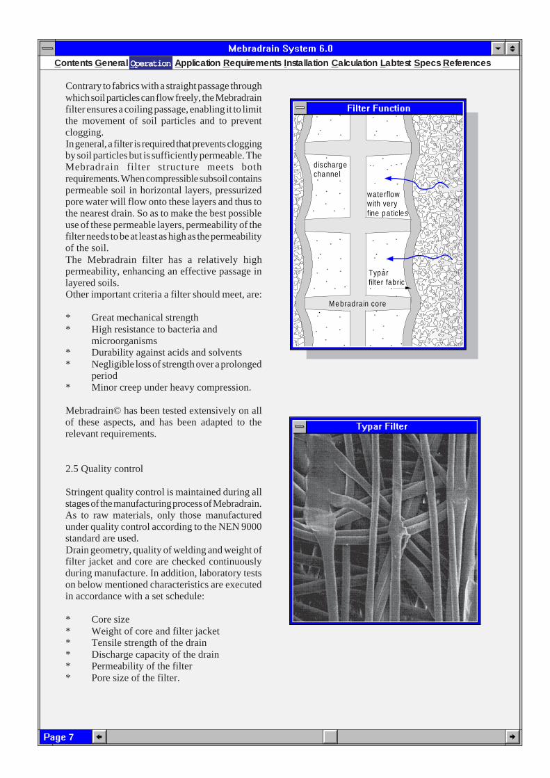
Contrary to fabrics with a straight passage throughwhich soil particles can flow freely, the Mebradrainfilter ensures a coiling passage, enabling it to limitthe movement of soil particles and to preventclogging.In general, a filter is required that prevents cloggingby soil particles but is sufficiently permeable. TheMebradrain filter structure meets bothrequirements. When compressible subsoil containspermeable soil in horizontal layers, pressurizedpore water will flow onto these layers and thus tothe nearest drain. So as to make the best possibleuse of these permeable layers, permeability of thefilter needs to be at least as high as the permeabilityof the soil.The Mebradrain filter has a relatively highpermeability, enhancing an effective passage inlayered soils.Other important criteria a filter should meet, are:
* Great mechanical strength* High resistance to bacteria and
microorganisms* Durability against acids and solvents* Negligible loss of strength over a prolonged
period* Minor creep under heavy compression.
Mebradrain© has been tested extensively on allof these aspects, and has been adapted to therelevant requirements.
2.5 Quality control
Stringent quality control is maintained during allstages of the manufacturing process of Mebradrain.As to raw materials, only those manufacturedunder quality control according to the NEN 9000standard are used.Drain geometry, quality of welding and weight offilter jacket and core are checked continuouslyduring manufacture. In addition, laboratory testson below mentioned characteristics are executedin accordance with a set schedule:
* Core size* Weight of core and filter jacket* Tensile strength of the drain* Discharge capacity of the drain* Permeability of the filter* Pore size of the filter.
OOOOOperationperationperationperationperation
8
Contents General Operation Application Requirements Installation Calculation Labtest S pecs References
3. APPLICATIONS
3.1 Consolidation
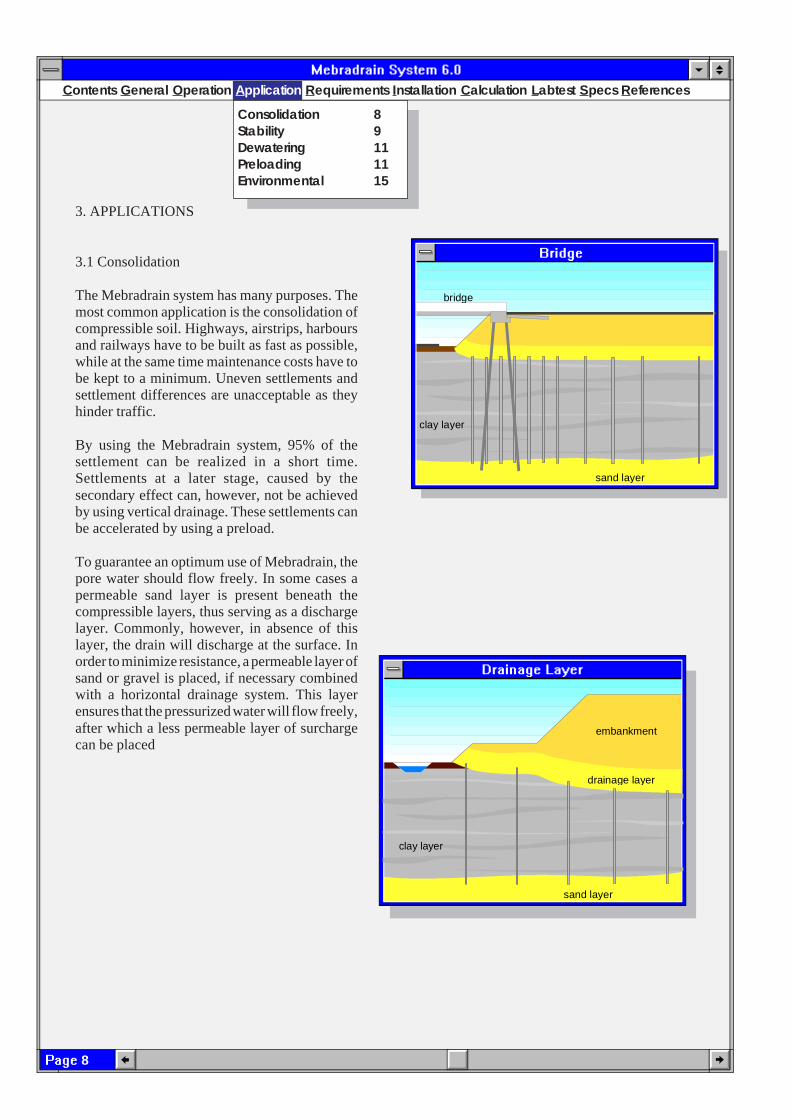
The Mebradrain system has many purposes. Themost common application is the consolidation ofcompressible soil. Highways, airstrips, harboursand railways have to be built as fast as possible,while at the same time maintenance costs have tobe kept to a minimum. Uneven settlements andsettlement differences are unacceptable as theyhinder traffic.
By using the Mebradrain system, 95% of thesettlement can be realized in a short time.Settlements at a later stage, caused by thesecondary effect can, however, not be achievedby using vertical drainage. These settlements canbe accelerated by using a preload.
To guarantee an optimum use of Mebradrain, thepore water should flow freely. In some cases apermeable sand layer is present beneath thecompressible layers, thus serving as a dischargelayer. Commonly, however, in absence of thislayer, the drain will discharge at the surface. Inorder to minimize resistance, a permeable layer ofsand or gravel is placed, if necessary combinedwith a horizontal drainage system. This layerensures that the pressurized water will flow freely,after which a less permeable layer of surchargecan be placed
Consolidation 8Stability 9Dewatering 11Preloading 11Environmental 15
Application
clay layer
sand layer
bridge
sand layer
embankment
clay layer
drainage layer
9
Contents General Operation Application Requirements Installation Calculation Labtest Specs References
Oil tanks and ore depots are often founded directlyon the subsoil, even in areas where soils are verycompressible. Because of the great fluctuation inweight, a dynamic stress is created whichinfluences the settlement and stability. Tankstend to sink into the soft subsoil, and specializedcompanies lift the tanks to their original positionand apply a layer of sand below the tanks. Thismethod is costly and vertical drainage, combinedwith a temporary surcharge, can materialize evensettlement in a short period. Vertical drainagebeneath oil tanks or other environmentally unsafeconstructions should never reach the deeperpermeable layers, to avoid future spreading of anypollution.
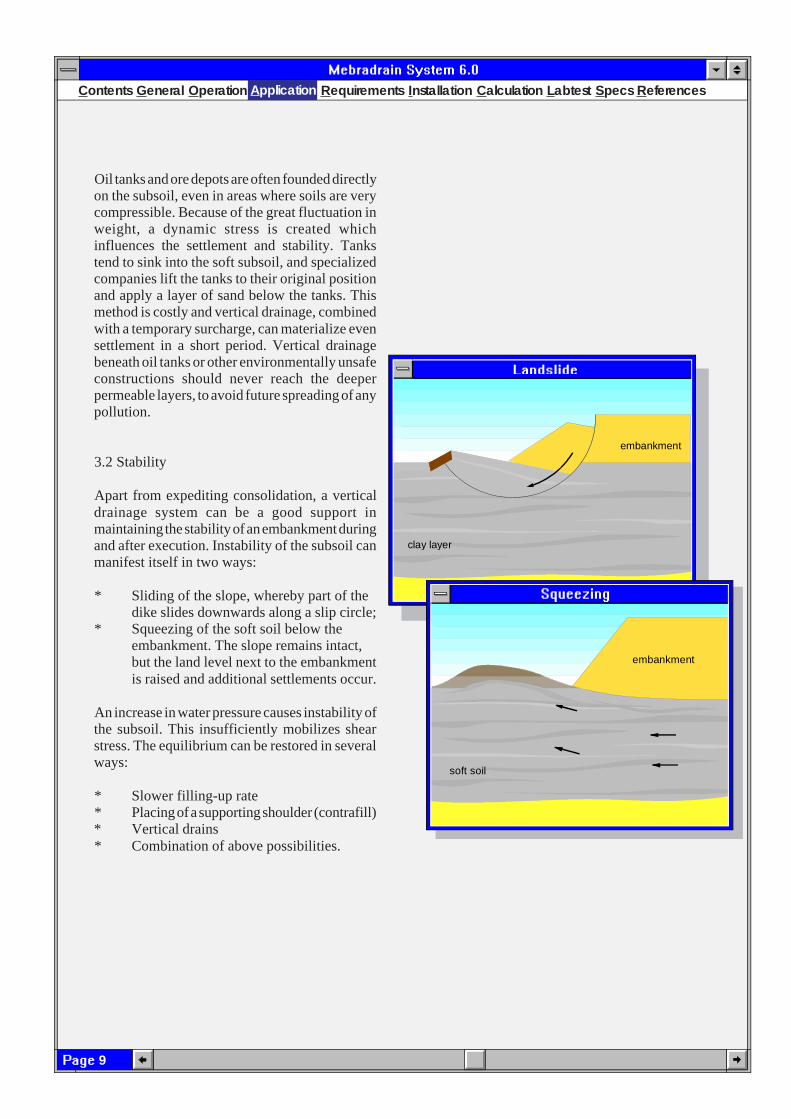
3.2 Stability
Apart from expediting consolidation, a verticaldrainage system can be a good support inmaintaining the stability of an embankment duringand after execution. Instability of the subsoil canmanifest itself in two ways:
* Sliding of the slope, whereby part of thedike slides downwards along a slip circle;
* Squeezing of the soft soil below theembankment. The slope remains intact,but the land level next to the embankmentis raised and additional settlements occur.
An increase in water pressure causes instability ofthe subsoil. This insufficiently mobilizes shearstress. The equilibrium can be restored in severalways:
* Slower filling-up rate* Placing of a supporting shoulder (contrafill)* Vertical drains* Combination of above possibilities.
clay layer
sand layer
embankment
embankment
soft soil
Application

10
Contents General Operation Application Requirements Installation Calculation Labtest S pecs References
For a certain situation, the equilibrium can becalculated by use of the slip surface calculationaccording to the generally applied Bishop method.Sliding can be prevented by calculating themaximum allowable excess pore pressure and bychecking this with pore pressure gauges duringfillingup. Design can be controlled by applyingshorter drain distances in those areas whereinstability may occur.
3.3 Dewatering
Mebradrain has been used in various projects as adewatering medium. In Germany, Mebradrain°has been used extensively as a horizontal drainagesystem on concrete motorways. Horizontal drainsare installed beneath the joints to prevent damageto the foundation caused by any leakages.Another common application is the dewatering ofthe topsoil in those places where a lowergroundwater level is present in the lowerdischarging layers. The surface water is drainedoff vertically to this layer through the drains. Nodrainage channels or other drainage systems arerequired to lower the groundwater level.A larger surface remains available for buildingpurposes, which is of special importance toindustrial areas.
Deep building pits are often drained with a wellsystem on the upper level of the slope. However,when the soil has a layered structure, making itimpossible for the groundwater to leakdown vertically, the groundwater will flowout on the slopes, with all its consequences.A vertical drainage system around thebuilding pit ensures groundwater at all levelsto be drained off downwards without anyobstacles.Moreover, the water pressure is spread overa larger triangle towards the pit, thusimproving stability. A lowering of thegroundwater level at the active side of thepiling of sheet-piling tubs can contribute toan optimum sheet-piling profile. clay layer
sand layer
Excavation
drains
watertable
well pump
clay layer
sand layer
embankment
drainage layer
slip circle
Application

11
Contents General Operation Application Requirements Installation Calculation Labtest Specs References
3.4 Pile foundation
Groundwater pressure can increase considerablyas a result of piledriving. Usually, this does notaffect the stability of the subsoil. However, whenpiledriving occurs in an excavation, it can lead tosuch instability that the pile foundation cancollapse. A vertical drainage system in theexcavation, or simply installing drains whilstpiledriving, can prevent many problems. Piles areburdened by settlements, resulting in the loss ofcarrying capacity (negative adhesion and/orinadmissible bending).
It is therefore advisable that a surcharge, possiblycombined with vertical drainage, is present beforepiledriving starts. Especially near slopes, greatforces can be exerted on the piles with all itsconsequences. In the past, many expensive pileconstructions, which could have been saved byusing a relatively inexpensive drainage system,were lost due to the above mentioned causes.
3.5 Preload
There are numerous methods, when combinedwith wick drains, which can speed upconsolidation. These methods do not only shortenthe consolidation time, but can also help in areaswhere a substantial primary settlement is expected.Primary settlements can be accelerated with theuse of vertical wick drains. Settlement occurswhen the soil is compressed. Compression takesplace logarithmically and is independent of theexisting pore pressure. With a preload by meansof a surcharge or a vacuum drain, the resultingsecondary settlement can be realized in a shorttime. By removing the preload, the original balanceof the soil will return.
clay layer
sand layer
Excavation
Piles
clay layer
sand layer
temporary overload
clay layer
sand layer
tankpark
Application
12
Contents General Operation Application Requirements Installation Calculation Labtest S pecs References
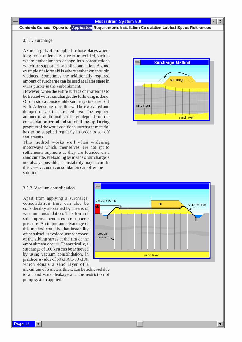
3.5.1. Surcharge
A surcharge is often applied in those places wherelong-term settlements have to be avoided, such aswhere embankments change into constructionswhich are supported by a pile foundation. A goodexample of aforesaid is where embankments joinviaducts. Sometimes the additionally requiredamount of surcharge can be used at a later stage inother places in the embankment.However, when the entire surface of an area has tobe treated with a surcharge, the following is done.On one side a considerable surcharge is started offwith. After some time, this will be excavated anddumped on a still untreated area. The requiredamount of additional surcharge depends on theconsolidation period and rate of filling-up. Duringprogress of the work, additional surcharge materialhas to be supplied regularly in order to set offsettlements.This method works well when wideningmotorways which, themselves, are not apt tosettlements anymore as they are founded on asand cunette. Preloading by means of surcharge isnot always possible, as instability may occur. Inthis case vacuum consolidation can offer thesolution.
3.5.2. Vacuum consolidation
Apart from applying a surcharge,consolidation time can also beconsiderably shortened by means ofvacuum consolidation. This form ofsoil improvement uses atmosphericpressure. An important advantage ofthis method could be that instabilityof the subsoil is avoided, as no increaseof the sliding stress at the rim of theembankment occurs. Theoretically, asurcharge of 100 kPa can be achievedby using vacuum consolidation. Inpractice, a value of 60 kPA to 80 kPA,which equals a sand layer of amaximum of 5 meters thick, can be achieved dueto air and water leakage and the restriction ofpump system applied.
sand layer
surcharge
clay layer
vertical drains
vacuum pumpfill VLDPE-liner
sand layer
Application

13
Contents General Operation Application Requirements Installation Calculation Labtest Specs References
Vacuum consolidation is created as follows:
A sand layer of at least 50 cm thick isapplied onto the site to be consolidated.From this layer Mebradrain® is installedup to a depth of max. 1 m above the deepersand layers. The vertical drainage shoulddefinitely not run into the permeabledischarging layers, as too large a flow ofwater will occur, preventing the formationof a vacuum. In the sand layer, horizontaldrains are installed on an interval of 5 m,and are connected to a vacuum pump. Awell pump which pumps both water andair makes it possible to realize a vacuumof 70 kPa to 95 kPa.The site is covered with a flexible, 1 mmthick VLDC-liner which is dug in on thesides, so that no flow of water and/or air ispossible from the sides. The liner shouldbe placed and sealed with the necessary care andfollow settlement without tearing. In a number ofprojects, unskilled execution of the linerconstruction has led to disappointing results.VLDC liners (Conductive Very Low Densityliners), however, can be tested on air tightnesswith the spark test so that pinholes can be localizedbefore the vacuum is applied. The linerconstruction has to be placed in accordance withthe guidelines as formulated for the execution oflining constructions at landfills. The seams haveto be carried out with a double seam,accommodated with a test channel. It isrecommended to build a dike around the site andto pump emerging groundwater onto the liner.The permeability of any perforations is thusconsiderably reduced and stepping on the liner,which could cause damage, is prevented. Therequired pump capacity strongly depends on theamount of affluent air and/or water.
0
2
4
6
8
10
12
14
16
100 200 300 40018
0
Pore pressure
atmosfericpressure
water table
dept
h (m
)
total stress
pressure (kPa)
effectivestress
0
2
4
6
8
10
12
14
16
100 200 300 40018
0
atmosfericpressure
dept
h (m
)
Pore pressure
pressure (kPa)
total stress
effectivestress
0
2
4
6
8
10
12
14
16
100 200 300 40018
0
Pore pressure
atmosfericpressure
dept
h (m
)
total stress
pressure (kPa)
effectivestress
Application
14
Contents General Operation Application Requirements Installation Calculation Labtest S pecs References
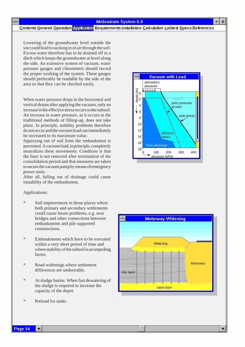
Lowering of the groundwater level outside thesite could lead to sucking in of air through the soil.Excess water therefore has to be drained off to aditch which keeps the groundwater at level alongthe side. An extensive system of vacuum, waterpressure gauges and clinometers should recordthe proper working of the system. These gaugesshould preferably be readable by the side of thearea so that they can be checked easily.
When water pressure drops in the horizontal andvertical drains after applying the vacuum, only anincrease in the effective stress occurs in the subsoil.An increase in water pressure, as it occurs in thetraditional methods of filling-up, does not takeplace. In principle, stability problems thereforedo not occur and the vacuum load can immediatelybe increased to its maximum value.Squeezing out of soil from the embankment isprevented. A vacuum load, in principle, completelyneutralizes these movements. Condition is thatthe liner is not removed after termination of theconsolidation period and that measures are takento secure the vacuum pump by means of emergencypower units.After all, falling out of drainage could causeinstability of the embankment.
Applications:
* Soil improvement in those places whereboth primary and secondary settlementscould cause future problems, e.g. nearbridges and other connections betweenembankments and pile supportedconstructions.
* Embankments which have to be executedwithin a very short period of time andwhere stability of the subsoil is an impedingfactor.
* Road widenings where settlementdifferences are undesirable.
* At sludge basins. When fast dewatering ofthe sludge is required to increase thecapacity of the depot.
* Preload for tanks
0
2
4
6
8
10
12
14
16
100 200 300 40018
atmosfericpressure
0
Pore pressure
pore pressureat start
dept
h (m
)
pressure (kPa)
total stress
effectivestress
clay layer
sand layer
Motorway
Widening
Application

15
Contents General Operation Application Requirements Installation Calculation Labtest Specs References
3.5.3. Deep well point system
A third method of expediting consolidation isplacing a well point system in the deeper soillayers. This reduces the ascent in the drain to zero,causing a larger potential difference with thesurrounding soil. This leads to faster consolidationthan without a deep well point system. Adjoininggraph shows the results of a testfield in Swedenwhere the settlements of three comparable sectionswere provided with vertical drainage, well pointsand vacuum load.
Literature:Vacuum-consolidatie toegepastin Streefkerk. K.F.Brons, A.F. Kool, E. Janse (Vacuum consolidationapplied in Streefkerk, the Netherlands).Construeren met grond, CUR (Construction withsoil).Soil improvement using vertical band drains andvacuum preloading at section 6/7, K.S. Sehested,Y.T. Seng.Consolidation of clay using vacuum method andwellpoint system in combination with verticaldrains, B.A. Torstensson.Vacuumconsolidatie, KIVI (Vacuumconsolidation).
3.6. Environmental technique
3.6.1. Landfills
Landfills are often filled to a great height. Thiscreates huge loads on the subsoil and thereforelarge settlements. This could jeopardize the qualityof the bottom liner. Both mineral seals and linerscan give way as a result of irregular settlementsand thus lose their function, with all itsconsequences.A vertical draining system combined with a preloadcan prematurely enforce a large part of thesettlements, so that large loads on the bottom sealfail to occur at a later stage. After completion ofthe preload system, the drains should be sealed offor removed to preclude pollution of the subsoilduring any calamities.
sand layer
embankment
clay layer
Well pump
0 50 100 150 200
100
200
300
400
500
600
700
Wellpoints with vertical drains
Wellpoints only
Vacuum with drains
Time (days)
Set
tlem
ent (
mm
)
Application

16
Contents General Operation Application Requirements Installation Calculation Labtest S pecs References
3.6.2. Sludge depots
Polluted harbour mud, process sludge from watertreatment plants, industries or mines have to bestored in isolated depots. This kind of mud has aparticularly high water content which takes up alarge part of the available, expensive, storagespace.With the Mebradrain system, either combinedwith a preload or with a vacuum system, thecapacity of such depots can be extendedconsiderably. Using special equipment, drainscan be installed from the sludge surface into thedrainage layer on top of the liner sealing. Bydraining off this drainage layer, acceleratedsettlement of the sludge occurs. Depending on thetype of sludge storage, capacity can be extendedby 50%.
3.6.3. Soil cleaning
One of the least expensive methods ofcleaning soil is the in situ rinsing method:a vertical drainage system in whichevery other drain is connected to thedeeper sand layer and every other to theapplied drainage layer. The wholesystem is then connected to a vacuumsystem. The deep groundwater is suckedup through the drains, finds its waythrough the polluted soil and continuesits way via the adjoining drain to thesurface, where the groundwater iscleaned with a mobile cleaner.Mebradrain is made of polypropylene,a material with excellent resistance to alarge number of chemicals.
3.6.4. Degassing
Various gasses arise during decomposition oforganic refuse in rubbish dumps. This dump gasmainly consists of methane (60%) and carbondioxide (39%). The gas flows out slowly and isoften flared out with a complex pipe system toprevent corrosion of the top cover of the dump.
vacuumpump
VLDPE-liner
verticaldrains
sand layer
pollution
Application

17
Contents General Operation Application Requirements Installation Calculation Labtest Specs References
Degassing can be expedited in a relativelyinexpensive way with a vertical drainage system.Settlements in dumps are realized within a shortperiod of time, enabling covering of the dump atan early stage. The vertical drain is connected toa gas flare system which is placed below the topseal of the dump. A second advantage of a verticaldrainage system is the discharge of percolate tothe drainage pipes at the bottom of the dump. Badly permeable horizontal layers are often formedin dumps. These layers prevent the percolate from draining downwards, so that itwill flow out on the slopes. Vertical drainsform a free passage for verticaltransportation.Both core and filter of Mebradrain aremade of polypropylene, a material withexcellent chemical resistance. During theinstallation procedure, the installationequipment should be prevented fromdamaging the liner. A minimum distanceof 2 meters should be kept between theend of the lance and the seal.
4. Requirements
The requirements a prefab drain shouldmeet, largely depend on the followingcircumstances:
* Size of the settlement* Consolidation period* Drain length* Size of the embankment* Method of installation.
The required discharge capacity for pore watermust be guaranteed at all times to ensure the bestpossible settlement progress. In the Netherlands,the requirements for prefab drains are summarizedin a Classification schedule drawn up by the workgroup "Vertical drainage" of the C.R.O.W. (theDutch Centre for the issuance of rules andregulations and investigation in civil engineering).As to vertical drainage, C.R.O.W. formulated thefollowing requirements.
clay layer
sand layer
HDPE-liner
Landfill
Application
18
Contents General Operation Application Requirements Installation Calculation Labtest S pecs References
4.1 Drain strength
During installation high forces can occur in thestrip drains. Especiallywhen a vibrator is used to install the drains, largeaccelerations during free fall of the mandrel haveto be transferred to the drain roll. This createslarge forces that have to be absorbed by theelongation and strength of the drain.The diameter of the transportation rolls is of greatimportance, too. In the past, paper filters wereused that teared up, while the core stayed intact.These failures could not be detected because thedrain was not visible during installation. Thelimited elongation of the filter paper did not allowfor large forces in the drain.Therefore, the following mechanical requirementswere specified:
Elongation drain ed
> 2%Strength drain F
d> 0.5 kN
Elong. filter 0,5 kN e0.5kN
> 10%
For the guide rolls in the installation rig, thefollowing requirement was set:
diameter transportation rolls > 150 mm
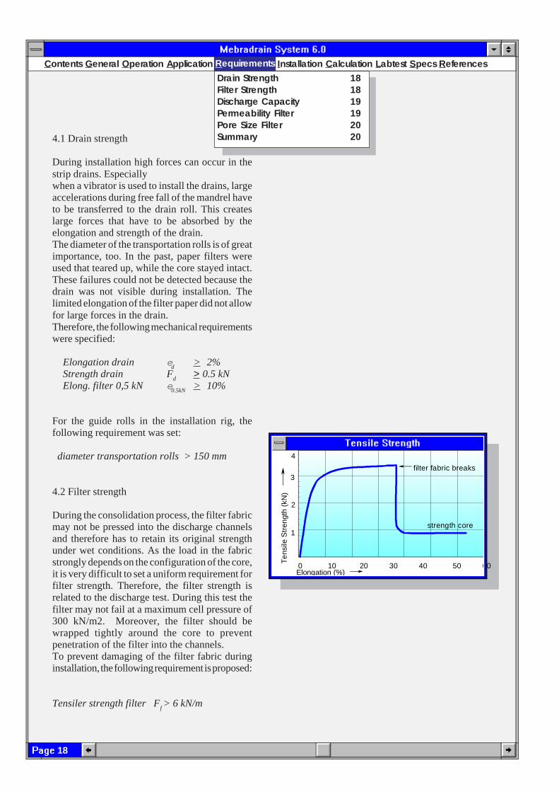
4.2 Filter strength
During the consolidation process, the filter fabricmay not be pressed into the discharge channelsand therefore has to retain its original strengthunder wet conditions. As the load in the fabricstrongly depends on the configuration of the core,it is very difficult to set a uniform requirement forfilter strength. Therefore, the filter strength isrelated to the discharge test. During this test thefilter may not fail at a maximum cell pressure of300 kN/m2. Moreover, the filter should bewrapped tightly around the core to preventpenetration of the filter into the channels.To prevent damaging of the filter fabric duringinstallation, the following requirement is proposed:
Tensiler strength filter Ff > 6 kN/m
0 10 20 30 40 50 60
4
3
2
1
filter fabric breaks
strength core
Ten
sile
Str
engt
h (k
N)
Elongation (%)
RequirementsDrain Strength 18Filter Strength 18Discharge Capacity 19Permeability Filter 19Pore Size Filter 20Summary 20

19
Contents General Operation Application Requirements Installation Calculation Labtest Specs References
4.3. Flow capacity of prefab drains
When calculating vertical drainage systems, theresistance in the drain is taken as zero. The flowcapacity is determined by the free volume of thedrain. The free volume is influenced by thecompression of the core and the depression of thefilter in the channels as a result of the horizontalsoil pressure. Depending on the length of thedrain, the filling speed, the compression and theultimate load, the discharge capacity of a prefabdrain (q
w) generally has to meet the following
requirements:
Drain length < 10 m and no stability problems:
qw(straight)
> 10x10-6 m³/s = 315 m³/yrq
w(buckeld)> 7.5x10⁻⁶ m³/s = 236 m³/yr
Drain length > 10 m and/or stability problems:
qw(straight)
> 50x10-6 m³/s = 1575 m³/yrq
w(buckled)> 32.5x10⁻⁶ m³/s = 1183 m³/yr
The discharge capacity of prefab drains isdetermined in accordance with the method asdescribed in chapter "Lab tests" of this paper.
4.4. Permeability of the filter
Pore water should be enabled to enter the drainwithout too much resistance. Tests with filters arealways carried out with clean water and a cleanfilter. Nowadays, permittivity is usuallyconsidered as the calculating value forpermeability (Y = k
f/d
f). However, as a result of
the flowing out of soil particles, the filter will siltup fast, lowering permittivity by a factor 1000.Permittivity of the filter must therefore be a factor1000 larger than most permeable soil types inwhich vertical drainage is applied.The filter criterion will then be:
Y >5 x 10⁻³ /s
Permittivity is determined in conformity with theNEN 5167 standard.
R equirements
20
Contents General Operation Application Requirements Installation Calculation Labtest S pecs References
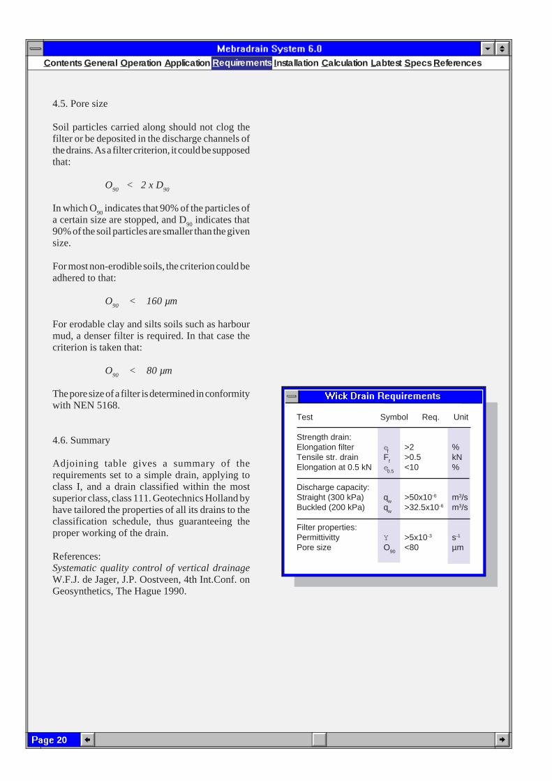
Test Symbol Req. Unit
Strength drain:Elongation filter e
f>2 %
Tensile str. drain Ff
>0.5 kNElongation at 0.5 kN e
0.5<10 %
Discharge capacity:Straight (300 kPa) q
w>50x10-6 m3/s
Buckled (200 kPa) qw
>32.5x10⁻⁶ m3/s
Filter properties:Permittivitty Y >5x10⁻³ s-1
Pore size O90
<80 µm
4.5. Pore size
Soil particles carried along should not clog thefilter or be deposited in the discharge channels ofthe drains. As a filter criterion, it could be supposedthat:
O90
< 2 x D90
In which O90
indicates that 90% of the particles ofa certain size are stopped, and D
90 indicates that
90% of the soil particles are smaller than the givensize.
For most non-erodible soils, the criterion could beadhered to that:
O90
< 160 µm
For erodable clay and silts soils such as harbourmud, a denser filter is required. In that case thecriterion is taken that:
O90
< 80 µm
The pore size of a filter is determined in conformitywith NEN 5168.
4.6. Summary
Adjoining table gives a summary of therequirements set to a simple drain, applying toclass I, and a drain classified within the mostsuperior class, class 111. Geotechnics Holland byhave tailored the properties of all its drains to theclassification schedule, thus guaranteeing theproper working of the drain.
References:Systematic quality control of vertical drainageW.F.J. de Jager, J.P. Oostveen, 4th Int.Conf. onGeosynthetics, The Hague 1990.
Requirements

21
Contents General Operation Application Requirements Installation Calculation Labtest Specs References
120 m m
50 m m6 m m
5. Installation
5.1. General
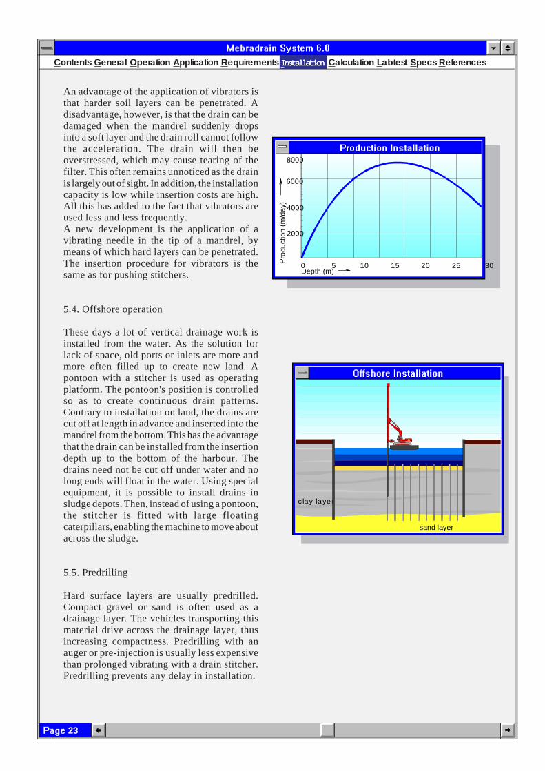
In order to prevent damage to and smearing of thedrain, a rectangled steel pipe is used to install theprefab drain. The size of this mandrel is minimal,in order to prevent resistance during installationand to avoid disturbance of the subsoil. In thecourse of time, numerous different types ofmachines have been constructed to move themandrel up and down as quickly as possible.In general, these machines, the so-called drainstitchers, can be divided into two groups: thestatic machines, pushing the mandrel into the soil,andthe dynamic machines, vibrating themandrel into the soil. Testing for theeffect of both systems has taught us thatthe method of insertion has no influenceon the ultimate effect of the drain. Thepros and cons of these systems are dealtwith in the following chapters.Depending on the insertion system, thesubsoil and the circumstances, dailyproduction can range from 1,000 to10,000 m. The effect of the insertiondepth on production is shown inadjoining graph. As installation costscover at least 50% of the total costs,very short or very longdrains are found to be, relatively, considerablymore expensive. Moreover, the price of anaccessory anchor plate for short drains is a majorexpense factor.
5.2. Pushing
There is a great variety of machines that pushinstallation mandrels into the soil. The first usedmachines pulled a diamond-shaped, as regardssectional view, mandrel through transportationrolls. The rather weak insertion pipe had to besupported along the entire length. Later on,stitchers were designed which pulled the mandrelinto the soil using a steel cable, driven by ahydraulic winch or ram. Here, too, facilities arerequired to restrict buckling length. Besides these,machines were developed that pushed the mandreldownwards by direct drive.
Disturbed zone sanddrain Disturbed zone Mebradrain
General 21Pushing 21Vibration 22Offshore 23Redrilling 23
IIIIInstallationnstallationnstallationnstallationnstallation
22
Contents General Operation Application Requirements Installation Calculation Labtest S pecs References
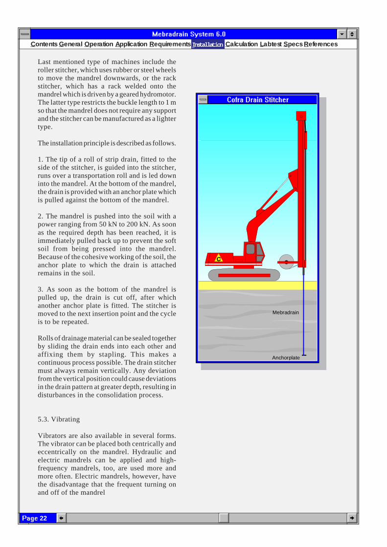
Last mentioned type of machines include theroller stitcher, which uses rubber or steel wheelsto move the mandrel downwards, or the rackstitcher, which has a rack welded onto themandrel which is driven by a geared hydromotor.The latter type restricts the buckle length to 1 mso that the mandrel does not require any supportand the stitcher can be manufactured as a lightertype.
The installation principle is described as follows.
1. The tip of a roll of strip drain, fitted to theside of the stitcher, is guided into the stitcher,runs over a transportation roll and is led downinto the mandrel. At the bottom of the mandrel,the drain is provided with an anchor plate whichis pulled against the bottom of the mandrel.
2. The mandrel is pushed into the soil with apower ranging from 50 kN to 200 kN. As soonas the required depth has been reached, it isimmediately pulled back up to prevent the softsoil from being pressed into the mandrel.Because of the cohesive working of the soil, theanchor plate to which the drain is attachedremains in the soil.
3. As soon as the bottom of the mandrel ispulled up, the drain is cut off, after whichanother anchor plate is fitted. The stitcher ismoved to the next insertion point and the cycleis to be repeated.
Rolls of drainage material can be sealed togetherby sliding the drain ends into each other andaffixing them by stapling. This makes acontinuous process possible. The drain stitchermust always remain vertically. Any deviationfrom the vertical position could cause deviationsin the drain pattern at greater depth, resulting indisturbances in the consolidation process.
5.3. Vibrating
Vibrators are also available in several forms.The vibrator can be placed both centrically andeccentrically on the mandrel. Hydraulic andelectric mandrels can be applied and high-frequency mandrels, too, are used more andmore often. Electric mandrels, however, havethe disadvantage that the frequent turning onand off of the mandrel
Anchorplate
Mebradrain
IIIIInstallationnstallationnstallationnstallationnstallation
23
Contents General Operation Application Requirements Installation Calculation Labtest Specs References
An advantage of the application of vibrators isthat harder soil layers can be penetrated. Adisadvantage, however, is that the drain can bedamaged when the mandrel suddenly dropsinto a soft layer and the drain roll cannot followthe acceleration. The drain will then beoverstressed, which may cause tearing of thefilter. This often remains unnoticed as the drainis largely out of sight. In addition, the installationcapacity is low while insertion costs are high.All this has added to the fact that vibrators areused less and less frequently.A new development is the application of avibrating needle in the tip of a mandrel, bymeans of which hard layers can be penetrated.The insertion procedure for vibrators is thesame as for pushing stitchers.
5.4. Offshore operation
These days a lot of vertical drainage work isinstalled from the water. As the solution forlack of space, old ports or inlets are more andmore often filled up to create new land. Apontoon with a stitcher is used as operatingplatform. The pontoon's position is controlledso as to create continuous drain patterns.Contrary to installation on land, the drains arecut off at length in advance and inserted into themandrel from the bottom. This has the advantagethat the drain can be installed from the insertiondepth up to the bottom of the harbour. Thedrains need not be cut off under water and nolong ends will float in the water. Using specialequipment, it is possible to install drains insludge depots. Then, instead of using a pontoon,the stitcher is fitted with large floatingcaterpillars, enabling the machine to move aboutacross the sludge.
5.5. Predrilling
Hard surface layers are usually predrilled.Compact gravel or sand is often used as adrainage layer. The vehicles transporting thismaterial drive across the drainage layer, thusincreasing compactness. Predrilling with anauger or pre-injection is usually less expensivethan prolonged vibrating with a drain stitcher.Predrilling prevents any delay in installation.
0 5 10 15 20 25 30 Depth (m)
2000
4000
6000
8000
Pro
duct
ion
(m/d
ay)
sand layer
c lay layer
IIIIInstallationnstallationnstallationnstallationnstallation
24
Contents General Operation Application Requirements Installation Calculation Labtest S pecs References
6. Calculation method
The principle of vertical drainage is relativelysimple. The theoretical description of theoperating mechanism is complex. The draindistance is generally calculated by use ofundermentioned Barron formula.
Ch = D2/8t [ ln D/d - ¾ + ¼(d/D)² ] ln (1-U)-1 (2)
in which:
t = consolidation time (s)C
h= consolidation coefficient for horizontal
flow (m2/s)d = drain diameter (m)D = diameter of the drain's influence zone (m)U = average degree of consolidation at
horizontal flow
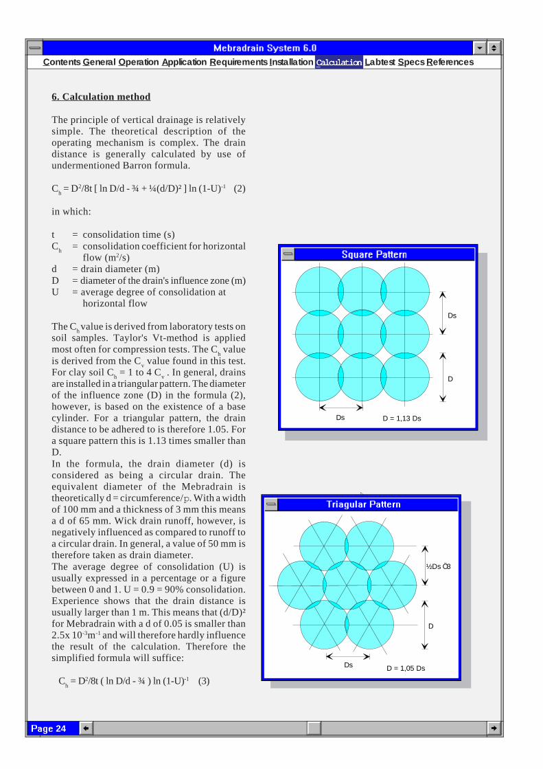
The Ch value is derived from laboratory tests on
soil samples. Taylor's Vt-method is appliedmost often for compression tests. The C
h value
is derived from the Cv value found in this test.
For clay soil Ch = 1 to 4 C
v . In general, drains
are installed in a triangular pattern. The diameterof the influence zone (D) in the formula (2),however, is based on the existence of a basecylinder. For a triangular pattern, the draindistance to be adhered to is therefore 1.05. Fora square pattern this is 1.13 times smaller thanD.In the formula, the drain diameter (d) isconsidered as being a circular drain. Theequivalent diameter of the Mebradrain istheoretically d = circumference/p. With a widthof 100 mm and a thickness of 3 mm this meansa d of 65 mm. Wick drain runoff, however, isnegatively influenced as compared to runoff toa circular drain. In general, a value of 50 mm istherefore taken as drain diameter.The average degree of consolidation (U) isusually expressed in a percentage or a figurebetween 0 and 1. U = 0.9 = 90% consolidation.Experience shows that the drain distance isusually larger than 1 m. This means that (d/D)²for Mebradrain with a d of 0.05 is smaller than2.5x 10-3m-1 and will therefore hardly influencethe result of the calculation. Therefore thesimplified formula will suffice:
Ch = D2/8t ( ln D/d - ¾ ) ln (1-U)-1 (3)
½Ds 3
Ds
D
D = 1,05 Ds
Ö
Ds
Ds
D
D = 1,13 Ds
CCCCCalculationalculationalculationalculationalculation

25
Contents General Operation Application Requirements Installation Calculation Labtest Specs References
Soil type k (m/s) kc/q
w (m-2)
Course sand 10-2 - 10-3 1000 - 1000Sand 10-3 - 10-4 100 - 10Fine sand 10-4 - 10-5 10 - 1Silty sand 10-5 - 10-6 1 - 10-1
Sandy silt 10-6 - 10-9 10-1 - 10-4
Peat 10-7 - 10-9 10-2 - 10-4
Clay 10-9 - 10-11 10-4 - 10-6
Apart from other data, this formula assumesthat the drain discharge resistance is zero.Mebradrain, however, has a limited dischargecapacity(q
w= 10-4 tot 10-5m3/s) , which can
considerably influence consolidation time,especially when long drains are used. Accordingto the Hansbo theory, the discharge capacitycan also be derived from the formula as follows:
Ch = D2/8t [lnD/d -¾ + pz (2L-z) k
c/q
w] ln (1-U)-1 (4)
where:z = distance to runoff point (m)L = drain length for one-sided flow (m)
(half length for two sided flow)k
c= soil permeability (m/s)
qw
= discharge capacity drain (m3/s)
The discharge capacity (qw) of Mebradrain is
approx. 5 x 10⁻⁵ m3/s, which is 10 times largerthan a sanddrain with a diameter of 300 mm.Permeability of strongly compressible soil (k
c)
ranges from 10-7 tot 10-11 m/s. Adjoiningschedule shows the k-values and ratio k
c/q
w in
order of size for different soil types. A qw van
10-5 m3/s is assumed here.The discharge capacity of the drain willinfluence the progress of consolidation whenthe ratio is k
c/q
w > 10-4 m-2. For Mebradrain this
means that the consolidation process isinfluenced when soil types have a permeability> 10-9 m/s het consolidatieproces wordtbeïnvloed.Formula (4) makes it possible to determineconsolidation for horizontal runoff at a certaindepth z. The progress of the averageconsolidation over the thickness of astratification equals the consolidation at a depthranging from 0.3 to 0.5 l. When as averagevalue z=0.41 is substituted in formula (4) thefollowing formula is obtained.
Ch = D2/8t [lnD/d - ¾ + p.0,64L²k
c/q
w] ln (1-U)-1
An MSDOS calculating program is availablefor interested parties. This program is based onBarron's calculating theory and calculates themost economic drain distance. This programsimultaneously calculates the average degreeof consolidation for vertical and horizontalrunoff. Also, using the Carrillo theory, theaverage degree of consolidation is calculatedfor the combined occurrence of vertical andhorizontal flow.
CCCCCalculationalculationalculationalculationalculation

26
Contents General Operation Application Requirements Installation Calculation Labtest S pecs References
U (% ) C (m ²/s)h
90 80 70 60 50 40
95
99
10 2 4 6 8-9 10 2 4 6 8-8 -710 2 4 6 8 10 -6
1
1 .5
2
3
4
6
8
1 2
1 6
2 4
3 6
4 8
4 05 0
6 07 0
8 0
9 09 59 9 U (% )
4 03 53 02 5
2 0
1 5
1 04 03 02 05
D rain len g th (m )if k / q < 0 .0 0 1 mc w
-2
D rain len g th (m )if k / q < 0 .0 1 mc w
-2
0 .5 0 .6 0 .7 0 .8 0 .9 1 1 .2 1 .5 1 .7 2 2 .5 3 4 5 6 7 8 9 1 0
D ra in d is tan ce (m ) if k / q < 0 .0 0 0 1 mc w-2
1 0987
6
5
4
0 .91 .0
1 .2
1 .5
1 .7
2 .0
2 .5
3
0 .4
0 .5
0 .6
0 .7
0 .8
0 .2
0 .3
Formula (5) has been worked out in the graphbelow. The blue line gives an example of howthe graph may be used.
The coefficient for horizontal flow can eitherbe determined by compression tests ofundisturbed soil samples in a laboratory, or bymeasurements in situ with a pressure probe asdeveloped byTorstensson in 1978.
CCCCCalculationalculationalculationalculationalculation

27
Contents General Operation Application Requirements Installation Calculation Labtest Specs References
The probe is pushed down into the soil at aconstant rate of penetration. The generated excesspore pressure, An, in the soil around the probe iscontinuously recorded. By stopping thepenetration of the probe and recording the rate ofpore pressure dissipation, the coefficient ofconsolidation C
h can be calculated. It is
recommended to calculate the Ch at a dissipation
level of 50%, i.e. Du/Du0 = 0.5, in which:
Du = remaining excess pore pressure at time tDu
0= initial excess pore pressure
If the time needed for 50% dissipation of theexcess pore pressure is denoted t
50 then the C
h can
be calculated from the following expression:
Ch= r0
2/t50
in which ro = radius of the cylindrical filter. Back-
calculated field values of Ch from various verticaldrainage projects indicate a good correlation withthe C
h-values calculated from pore pressure
dissipation tests.
7. Laboratory tests
The properties and operation of Mebradrain° havebeen tested in independent laboratories. Reportsare available from these tests, in which thedischarge capacity of the drains were determinedin both straight and buckled forms. In addition, anextensive report is available on test fields andrealized projects.
7.1. Compression tests
In order to get a practical insight in the behaviourof Mebradrain in compressible soil, a number ofcompression tests were carried out on differenttypes of drains by using a test unit.This tester consisted of six steel cylinders 0500mm and 1200 mm high. A drain was tightened inthe centre line, after which the cylinder was filledwith a layer of soft soil and a layer of filtering sandon top. The bottom of the drain was clamped intothe bottom plate.
hydrauliccilinder
water inlet
water outlet
compressiblesoil
vertical drain
sand
LLLLLabtestabtestabtestabtestabtest
t 50Time (t in seconds)
Du/Du0
1
0.5
0
r0
filtertip
BAT Pore Pressure Test
28
Contents General Operation Application Requirements Installation Calculation Labtest S pecs References
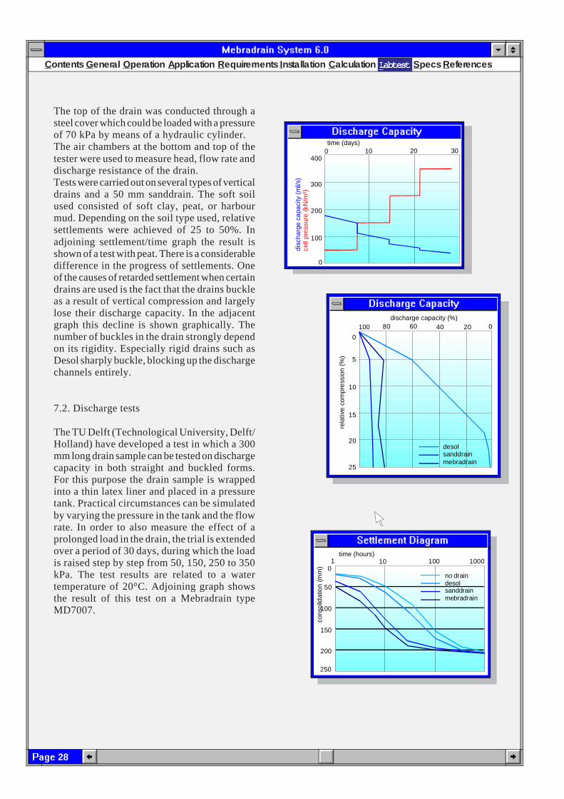
The top of the drain was conducted through asteel cover which could be loaded with a pressureof 70 kPa by means of a hydraulic cylinder.The air chambers at the bottom and top of thetester were used to measure head, flow rate anddischarge resistance of the drain.Tests were carried out on several types of verticaldrains and a 50 mm sanddrain. The soft soilused consisted of soft clay, peat, or harbourmud. Depending on the soil type used, relativesettlements were achieved of 25 to 50%. Inadjoining settlement/time graph the result isshown of a test with peat. There is a considerabledifference in the progress of settlements. Oneof the causes of retarded settlement when certaindrains are used is the fact that the drains buckleas a result of vertical compression and largelylose their discharge capacity. In the adjacentgraph this decline is shown graphically. Thenumber of buckles in the drain strongly dependon its rigidity. Especially rigid drains such asDesol sharply buckle, blocking up the dischargechannels entirely.
7.2. Discharge tests
The TU Delft (Technological University, Delft/Holland) have developed a test in which a 300mm long drain sample can be tested on dischargecapacity in both straight and buckled forms.For this purpose the drain sample is wrappedinto a thin latex liner and placed in a pressuretank. Practical circumstances can be simulatedby varying the pressure in the tank and the flowrate. In order to also measure the effect of aprolonged load in the drain, the trial is extendedover a period of 30 days, during which the loadis raised step by step from 50, 150, 250 to 350kPa. The test results are related to a watertemperature of 20°C. Adjoining graph showsthe result of this test on a Mebradrain typeMD7007.
10 20 30time (days)
100
300
200
0
4000
disc
harg
e ca
paci
ty (
ml/s
)ce
ll pr
ess
ure
(kN
/m²)
1 10 100 1000time (hours)
50
100
150
200
250
0
cons
olid
atio
n (
mm
)
no draindesolsanddrainmebradrain
discharge capacity (%)100 80 60 40 20 0
rela
tive
com
pre
ssio
n (%
)0
5
10
15
20
25
desolsanddrainmebradrain
LLLLLabtestabtestabtestabtestabtest

29
Contents General Operation Application Requirements Installation Calculation Labtest Specs References
Agent Effect
AcidsAcetic noneChromic noneHydrobromic noneHydrochloric noneSulfuric nonePhosphoric none
AlkalisAmmonia noneSodium hydroxide noneSodium hypochlorite none
Organic chemicalsAcetone noneBenzene moderateCyclohexanone noneEthanol noneEthylene Glycol noneDimethyl noneGasoline considerableMethylene chloride considarableTrichloorethene considerable
7.3. Pore size filter
The pore size of the filter is determined on thebasis of NEN 5168. Dry soil, split up in fractionsof the following sizes:
150 - 180 mm125 - 150 mm106 - 125 mm75 - 106 mm53 - 75 mm
is sieved through the filter, thus composing agrading diagram of particles slipping throughthe filter, thus composing a gradient diagram ofparticles slipping through the filter.The size of those particles of which 90% remainsbehind on the filter is called 0
90. The grading
diagram for the filter jacket of Mebradrain typeMD88 is given in adjoining graph. This graphshows that the average 0
90 of this jacket agrees
with 76 gm.
7.4. Permittivitty of the filter
The filter's permittivitty does not depend onfilter thickness and is therefore more suitable todetermine specific water permeability of thematerial. Permittivitty is water permeability/filter thickness and is expressed in s-1. (y = k/d). According to NEN 5167 permittivity of afilter cloth is related to the average value at awater temperature of 10°C and a filtration rateof 10 mm/s. The filter is subjected to a waterstream at right angles with the filter surface.The supply is increased stepwise, during whichthe occurring fall Dh over the synthetic filterand the discharge output Q are measured. Fromthe values found, the water permeability (k-value) is calculated in m/s.
7.5. Chemical resistance
Both the core and the jacket of Mebradrain° aremanufactured of polypropylene (PP). Thispolymer has an excellent chemical resistance,comparable to HDPE. Adjoining table showsthe resistance of PP at a temperature of 20°C.This high resistance to all kinds of chemicalsmakes Mebradrain highly suitable forenvironmental applications.
50 100 150 200filter opening (µm)
90
80
70
60
50
100
perc
enta
ge s
and
on fi
lter
(%)
LLLLLabtestabtestabtestabtestabtest

30
Contents General Operation Application Requirements Installation Calculation Labtest S pecs References
8. Specifications
8.1 General
8.1.1.The relevant details of the soil investigationsare stated in the appendix to the tenderspecification, or as the case may be areavailable for perusal in ...
8.1.2. Installation of vertical prefab drains takesplace from a drainage layer of at least 0.5 mthick and with a course grading.
8.1.3. Vertical drains should be installed inaccordance with the pattern shown in thedrawing.
8.1.4. The maximum allowable deviation of thespot of installing a drain in relation to the setpoint is 0.15 m. The maximum allowabledeviation of the vertical is 50:1, unlessobstacles are present, such as overgroundpower lines and foundation rests.
8.1.5. In those places where it is impossible toinstall a drain as a result of obstacles, anotherdrain must be installed within a distance of0.15 m.
8.1.6. Drains have to be installed up to the depth(s)shown in the drawing. Prefabricated drainsare cut off at 0.15 m above the surface.
8.1.7. During installation it must be possible toread off the insertion depth on the machine.
8.1.8. A registration must be kept on which number,length and place of the drains and date ofinstallation are noted.
8.1.9. The contractor should take it for granted thatinstrumentation of a total value of US$ ... ispresent at site. The contractor should see toit that the instrumentation to check theprogress of consolidation is not damagedduring execution of the work. Damagecaused is repaired on notification by theboard of directors for account of thecontractor or, where appropriate, thecontractor is fined to an amount of US$ ...for any equipment broken down through afault of his.
S pecs

31
Contents General Operation Application Requirements Installation Calculation Labtest Specs References
8.2. PREFAB DRAINS
8.2.1.Prefab drains supplied under a recognizedcertification with quality mark inconformity with the class required for thework and inspected at the work by theboard are considered to have been tested.
8.2.2. Prefab drains purchased from a producerwho is not entitled to supply under arecognized certificate with quality markin conformity with the class required forthe work have to be supplied per relevantlot in accordance with a lot-qualificationsystem.The supply of a lot in accordancewith a lot-qualification system of arecognized inspection service must meetthe following points:
* Type of inspection, not older than 6 monthsin conformity with theadjoining schedule, is inagreement with the classrequired for the work.
* During production andsupply at site the quality ofthe drain is checked inaccordance with the tests andfrequencies shown inadjoining schedule.
* None of the results of thesechecks will exceed theallowable deviationmentioned in the schedule ascompared to the averagevalues fixed at the type ofinspection. When theallowable deviation isexceeded, the entire manufactured or,where appropriate, supplied lot will berejected.
8.2.3.The equipment and installation methodrequire approval of the supervisor.
8.2.4. It is allowed to install the drain by meansof vibrating or pushing. In consultationwith the supervisor it is allowed to predrillor inject in hard layers.
aspects control type of factory control Allow.
schedule inspection > control on site devia.
beproeving Code number 1 sample
of tests per
1 core geometry EN ISO 9863 5 2.000m 10.000m 5%
2 core mass per metre EN ISO 9864 5 2.000m 10.000m 10%
3 mass filter. EN ISO 9864 5 2.000m 10.000m 25%
4 mass drain per metre EN ISO 9864 5 2.000m 10.000m 25%
5 tensile test drain EN ISO 10319 5 1.000km — 25%
6 discharge test CROW publ. 3 2.000km — 25%
7 discharge test buckled CROW publ. 3 2.000km — 25%
8 permeability filter EN ISO 12958 3 1.000km — 25%
9 pore size filter EN ISO 12956 3 1.000km — 25%
S pecs
32
Contents General Operation Application Requirements Installation Calculation Labtest S pecs References
8.2.5.The drain has to be anchored at the showndepth.
8.2.6. All material wasted during work has to beremoved from the building site. Anysludge has to be discharged.
8.2.7. During storage the drainage material hasto be sufficiently protected against anyinfluence of weather.
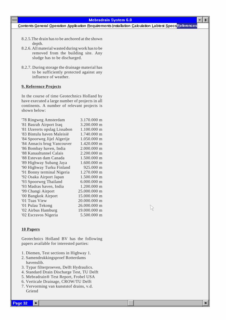
9. Reference Projects
In the course of time Geotechnics Holland byhave executed a large number of projects in allcontinents. A number of relevant projects isshown below:
'78 Ringweg Amsterdam 3.170.000 m'81 Basrah Airport Iraq 3.200.000 m'81 IJzererts opslag Lissabon 1.100.000 m'83 Bintulu haven Maleisië 1.740.000 m'84 Spoorweg Jijel Algerije 1.050.000 m'84 Annacis brug Vancouver 1.420.000 m'86 Bombay haven, India 2.000.000 m'88 Kanaaltunnel Calais 2.200.000 m'88 Estevan dam Canada 1.500.000 m'89 Highway Subang Jaya 1.600.000 m'90 Highway Turku Finland 925.000 m'91 Bonny terminal Nigeria 1.270.000 m'92 Osaka Airport Japan 1.500.000 m'93 Spoorweg Thailand 6.000.000 m'93 Madras haven, India 1.200.000 m'99 Changi Airport 25.000.000 m'00 Bangkok Airport 15.000.000 m'01 Tuas View 20.000.000 m'01 Pulau Tekong 26.000.000 m'02 Airbus Hamburg 19.000.000 m'02 Escravos Nigeria 5.500.000 m
10 Papers
Geotechnics Holland BV has the followingpapers available for interested parties:
1. Diemen, Test sections in Highway 1.2. Samendrukkingsproef Rotterdams havenslib.3. Typar filterproeven, Delft Hydraulics.4. Standard Drain Discharge Test, TU Delft5. Mebradrain® Test Report, Frobel USA6. Verticale Drainage, CROW/TU Delft7. Vervorming van kunststof drains, v.d. Griend
R eferences