the metal-enclosed, air insulated switchgear panels of the ...• iec 62271-1 for general purposes...
TRANSCRIPT


The metal-enclosed, air insulated switchgear panels of the UniTec-40 (ITC Technology), is designed for use in 36kV and 40.5kV; 3150A; 40KA systems. UniTec-40 is fully type tested in CESI/EPIL/KERI/LVT laboratories, they are designed for indoor applications. UniTec-40 medium-voltage primary switchgear offers the ideal combination of flexibility, reliability, availability, safety an economical solution for industrial and utility applications.

Untec-40 Characteristics • Metal-clad, air-insulated switchgear. • Suitable for medium voltage Distribution. • Guaranteed arc-proof units. • Factory-tested for indoor installations. • Tested in accordance with the main international Standards. • Wide range of functional units available for all installation solutions. • Compartments segregated by metallic partitions. • Highly effective use of space. • Start-up, maintenance and service operations can be carried out from the front. • Apparatus handling with the door closed. • Complete with mechanical safety interlocks. • Earthing switch with full short circuit withstand capacity. • Studied to guarantee maximum service continuity. • Complete apparatus range: Vacuum circuit-breakers • Conventional or integrated protection and measurement systems.
Untec-40 Applications
Utilities and Power Plants • Power generation stations • Substations • Main and auxiliary switchgear Industry • Pulp and Paper • Cement • Textiles • Food • Automotive • Quarrying • Petrochemical • Oil and gas • Metallurgy • Rolling mills • Mines
Marine • Drilling platforms • Off-shore oil rigs • Cruise ships • Container ships • Tankers • Cable ships • Ferries Transport • Airports • Ports • Railways • Underground transport Infrastructure • Shopping malls • Hospitals • Large infrastructure and civil works

Standards The switchgear and main apparatus contained in it comply with the following Standards: • IEC 62271-1 for general purposes • IEC 62271-200 for the switchgear • IEC 62271-102 for the earthing switch • IEC 62271-100 for the circuit-breakers • IEC 60071-2 for the insulation coordination • IEC 60529 for degree of protections Colour of the external surfaces RAL7032 - light grey (front doors and side sheets). Other colors available on request. Normal operation conditions The rated characteristics of the switchgear are guaranteed under the following ambient conditions: • Minimum ambient temperature: – 5 °C • Maximum ambient temperature: + 40 °C For different temperature ranges, please contact to ITC Sales representative. • The normal operational altitude is up to 1,000 m above sea level. For higher altitude applications, please contact ITC sales representative. • Presence of normal, non-corrosive and uncontaminated atmosphere.

Degrees of protection
The degrees of protection of the switchgear conform with IEC 60529 Standards. Unitec-40 switchgear is normally supplied with the following standard degrees of protection: • IP43 for the enclosure. • IP2X for the partition between compartments. On request, the external housing can be supplied with a higher degree of protection; in this case please contact ITC sales representative.
The electrical characteristics of the switchboard can vary for ambient conditions other than those described in the previous section and also if a higher degree of protection is used. IEC electrical characteristics of Unitec-40

Dimension
(1) The height of the unit (2420mm) is a function of the height of the low voltage compartment, / the height of the unit is a lateral walls. (2) The depth (3900mm) will be considered with installed with draw able PT in rear side.

With the release of the IEC 62271-200 standard, new definitions and classifications of Medium Voltage switchgear have been introduced.
One of the most significant changes is that classification of switchgear into metal-enclosed, compartmented and cubicle types has been abandoned.
The revision of switchgear classification rules has been based on the user’s point of view, in particular on aspects like service and maintenance of the switchgear, according to the requirements and expectations for proper management, from installation to dismantling. In this context, Loss of Service Continuity (LSC) has been selected as a fundamental parameter for the user. According to the IEC 62271-200, Unitec-40 switchgear can be defined as follows.
Loss of service continuity - LSC-2B
The various LSC categories describe the possibility of keeping other compartments and/or panels energized.
while a compartment in the main circuit is opened. The defined categories are:
LSC-1: The whole switchgear shall be put out of service for opening a main circuit compartment for normal operation and/or normal maintenance or for gaining access to any switchgear components.
LSC-2A: The same as LSC-1 with the exception that the main bus bars and the functional units adjacent to the one under maintenance can remain energized.
LSC-2B: the same as LSC-2A with the exception that the cable compartment can remain energized.
Unitec-40 is classified as LSC-2B because the bus bar, circuit-breaker and cable compartments are physically and electrically segregated. This is the category that defines the possibility of accessing the circuit-breaker compartment with the bus bars and cables energized.

Partition Metallic - PM
With regard to the type of partitions or shutters between live parts and an open compartment, a distinction is made between two partition classes:
class PM (Partition made of Metal)
class PI (Partition made of Insulating material)
Unitec-40 is defined with PM partition class having the segregation between compartments made of metallic sheets/ shutters.
Interlock-controlled accessible compartment
The front side of Unitec-40 is classified Tool-based & Key lock because the access of the compartments containing high- voltage parts, intended to be opened for normal operation and/or normal maintenance, is controlled by the integral design of the switchgear.
On request, Can be supplied interlocked C.B. Compartment door with CB position; in this case please contact ITC sales representative.
Tool-based accessible compartment
the rear part and doors of the Unitc-40 is classified tool-based because it is possible to open the compartment containing high-voltage parts, that may be opened, but not for normal operation and maintenance, only using a tool. Special procedures are required.
Internal arc classification – IAC AFLR
Unitc-40 switchgear is classified IAC AFLR. When the switchgear is specified and installed, some fundamental points must be taken into consideration:
Level of the fault current (16...40 kA).
Duration of the fault (0.1...0.3s).
Escape routes for the hot and toxic gases produced by combustion of materials.
Dimensions of the room, with special attention to the height. Please consult ITC representatives for detailed information.

Compartments
Each switchgear unit consists of three power compartments: circuit-breaker [A], bus bars [B] and cables [C]; please refer to figure 1.
Each unit is fitted with a low voltage compartment [D], where all the auxiliary instruments are housed. Arc-proof switchgear is optional provided with a duct [E] for evacuation of the gases produced by an arc.
All the compartments are accessible from the front, and cable compartment can be rear access. The compartments are segregated from each other by metallic partitions.
Main bus bars
The bus bar compartment contains the main bus bar system connected to the upper isolating contacts of the circuit- breaker by means of branch connections.
The main bus bars are made of electrolytic copper. Special D-shape/ Flat shape bus bar is used. The bus bars are covered with insulating material.
Cable connections
The cable compartment contains the branch system for connection of the power cables to the lower contacts of the circuit-breaker.
The feeder connections are made of electrolytic copper and they are flat bus bars for the whole range of currents.
They are insulated of together with insulating material.

Earthing switch
Cable compartment can be fitted with an earthing switch for cable earthing.
It can also be installed directly on the main bus bar system in a dedicated compartment (bus bar applications).
Control of the earthing switch is from the front of the switchgear with manual operation.
The position of the earthing switch can be seen from the front of the switchgear by means of an indicator on the main mechanism.
Earthing bus bar
The earthing bus bar is made of electrolytic copper and it runs longitudinally throughout the switchgear, thereby guaranteeing maximum personnel and installation safety.
Insulating bushings and shutters
The insulating bushings in the circuit-breaker compartment contain the contacts for connection of the circuit-breaker with the bus bar compartment and cable compartment respectively. The insulating bushings are of single-pole type and are made of epoxy resin. The shutters are metallic (For 1250 A) and are activated automatically during movement of the circuit-breaker from the racked-out position to the operation position and vice versa.
Cables
Single and three-core cables up to a maximum of 10 per phase can be used.

Unit compartments
A: Circuit-breaker compartment B: Bus bar Compartment C: Cable compartment D: Low voltage compartment Figure 1: Unitec-40 single level section view
.

The Unitec-40 switchgear has undergone all mandatory tests required by the international (IEC) Standards.
IEC type tests
• Short-time and peak withstand current • Temperature rise • Internal arc capability • Dielectric test • Making and breaking capacity of circuit-breaker • Earthing switch • Mechanical operations of circuit-breaker and earthing switch • IP protection degree
IEC routine factory tests
• Visual inspection and check • Mechanical sequence operations • Cabling check • Electrical sequence operations • Power frequency withstand voltage • Measurement of the resistance of the main circuits • Secondary insulation test
Description of IEC TYPE-TESTED
• Short-time and peak withstand current (40KA-1s) The test shows that the main power and the earthing circuits resist the stresses caused by the passage of the short-circuit current without any damage. It should also be noted that both the earthing system of the withdraw able circuit-breaker and the earthing bus bar of the switchgear are subjected to the test. The mechanical and electrical properties of the main bus bar system and of the top and bottom branch connections remain unchanged even in the case of a short-circuit. • Temperature rise (3150 A & 1250 A) The temperature rise test is carried out at the rated current value of the switchgear unit and shows that the temperature does not become excessive in any part of the switchgear unit. During the test, both the switchgear and the circuit-breaker. • Internal arc capability (40KA, 0.3 S) • Dielectric test (36KV, 70KV, 170KV IEC) These tests verify that the switchgear has sufficient capability to withstand the lightning impulse and the power frequency voltage. The power frequency withstand voltage test is carried out as a type test, but it is also a routine test on every switchgear unit manufactured. • Circuit-breaker making and breaking capacity The circuit-breaker the rated current and short-circuit current breaking tests. Furthermore, it is also subjected to the opening and closing of capacitive and inductive loads, capacitor banks and/or cable lines.

• Mechanical operations The mechanical endurance test on all the operating parts ensures the reliability of the apparatus. General experience in the electro-technical sector shows that mechanical faults are one of the most common causes of a fault in an installation. The circuit-breaker is tested by carrying out a high number of operations - higher than those which are normally carried out by installations in the field. Furthermore, the switchgear components are part of a quality control program and samples are regularly taken from the production lines and subjected to mechanical life tests to verify that the quality is identical to that of the components subjected to the type tests. • IP Protection degree The IP protection degree is the resistance offered by the Unitec-40 against penetration of solid objects and liquids. This degree of resistance is indicated by the prefix IP followed by two characters (i.e. IP43). The first number identifies the degree of protection against the entrance of solid objects; the second one is related to liquids.

When developing modern medium voltage switchgear, personnel safety must necessarily take priority. This is why the Unitec-40 switchgear has been designed and tested to withstand an internal arc due to a short-circuit current of the same current level as the maximum short- time withstand level. The tests show that the metal housing of Unitec-40 switchgear is able to protect personnel near the switchgear in the case of a fault which evolves as far as striking an internal arc. An internal arc is a highly unlikely fault, although it can theoretically be caused by various factors, such as : • Insulation defects due to quality deterioration of the components. The reasons can be adverse environmental conditions and a highly polluted atmosphere. • Overvoltage’s of atmospheric origin or generated by the operation of a component. • Inadequate training of the personnel in charge of the installation. • Breakage or tampering of the safety interlocks. • Overheating of the contact area, due to the presence of corrosive agents or when the connections are not sufficiently tightened • Entry of small animals into the switchgear i.e. through cable entrance). • Material left behind inside the switchgear during maintenance activities.

The characteristics of the Unitec-40 switchgear notably reduce the incidence of these causes for faults, but some of them may not be eliminated completely. The energy produced by the internal arc causes the following phenomena: • Increase in the internal pressure. • Increase in temperature. • Visual and acoustic effects. • Mechanical stresses on the switchgear structure. • Melting, decomposition and evaporation of materials. The test also ensure that no holes are produced in external accessible parts of the housing, and finally, that all the connections to the earthing circuit remain intact, hence guaranteeing the safety of personnel who may access the switchgear after the fault. The IEC 62271-200 Standard describes the methods to be used for carrying out the test and the criteria which the switchgear must conform to. The Unitc-40 switchgear fully conforms to all the five criteria indicated by the IEC standards. The IAC classification is proved by the test according to the following designations: • General: classification IAC (Internal Arc Classified • Accessibility: A, B or C Switchgear accessible to authorized personnel only (A) To all (B) Not accessible due to installation (C) • F, L, R: access from the front (F – Front), from the sides (L – Lateral) and from the rear (R –rear). • Test values: test current in kilo amperes (kA), and duration in seconds (s). The parameters of each specific plant mean that evacuation of the hot gases and incandescent particles must be checked very carefully in order to ensure and maintain personnel safety.

The Unitec-40 switchgear is fitted with all the interlocks and accessories needed to guarantee the highest level of safety and reliability for both installation and personnel. Interlocks The safety mechanical interlocks are standard ones. They are set out by the IEC standards and are therefore necessary to guarantee the correct operation sequence. Keys (Optional) The use of key interlocks is very important in realizing the interlocking logics between panels of the same switchgear, or of other medium, low and high voltage switchgear. The logics are realized by means of distributors or by ringing the keys. The apparatus truck [4] can be locked in the racked- out position and the relevant lock key can only be removed with the apparatus in this position. The earthing switch closing [5] and opening [6] operations can be locked by means of keys; These locks can also be applied to the earthing switch of bus bar applications. The key lock can also be applied to the earthing switch of bus bar applications. The keys can always be removed.
lock on earthing switch

8 Apparatus racking-in/out Magnet energized
9 Earthing switch ON/OFF Magnet energized
Locking magnets The locking magnets enable automatic interlocking logics without human intervention. The earthing switch closing operations can be interlocked. This magnet can also be applied to the earthing switch of bus bar applications. The magnets operate with active logics and therefore the lack of auxiliary voltage leaves the interlocking system active in safety condition. Types of interlocks
Standard safety interlocks (mandatory)
Type Description
Apparatus racking-in/out
Condition to be met
Apparatus in open position 1
A
B Apparatus closing Defined truck position
2 A Apparatus racking-in Apparatus multi-contact plug plugged
B Apparatus multi-contact plug unplugging Truck in test position
3 A Earthing switch closing Truck in test position
B Apparatus racking-in Earthing switch in open position
Note: Apparatus are circuit-breakers
Keys (on request)
4 Apparatus racking-in lock Can only be removed with the truck in the racked-out 5 Earthing switch closing lock Can only be removed with the earthing switch open 6 Earthing switch opening lock Can only be removed with the earthing closed 7 Insertion of the apparatus raking-in/out Can always be removed
Locking magnets (on request)

HVF circuit-breaker The circuit breakers shall be rated 36 Kv, 60/ 50 Hz, having a continuous current rating of (1250-3150) amperes and interrupting rating of (3500-1000) MVA. All circuit breakers of equal rating shall be completely interchangeable. The circuit breaker shall operate by means of a stored energy mechanism, which is normally charged by a small universal motor, but which can also be charged by a manual handle for emergency manual closing or test. The mechanism shall be so arranged that the closing speed of the contacts is independent of both control voltage and the operator. The circuit breaker shall have three independent vacuum interrupters, one per phase. The circuit breaker shall be equipped with secondary disconnecting contacts which shall automatically engage in the operating and test position to complete circuits as required. The contacts shall automatically disengage when the circuit breaker is withdrawn to the disconnect position. The circuit breaker shall have a means for racking in and out of the compartment and between positions. It shall furthermore be provided with a means of holding the circuit breaker in the compartment in all positions. Interlocking shall be provided to make it impossible to rack a closed circuit breaker to or from any position. An additional inter-lock shall be provided which shall assure automatic discharging of the closing springs upon Insertion or removal of the breaker into or out of the compartment The circuit breaker control voltage shall be (48-125-250 DC; 115-230 AC, 60/ 50 Hz) HYUNDAI vacuum circuit breakers may be operated at ambient temperatures between -25� and +40�. The rated normal currents are determined according to IEC standards at an ambient temperature of 40�.

When the breakers are operated at different temperatures, the correction on the operating current must be considered. Fig.9 shows appropriate operating currents at different ambient temperatures. However, the diagram applies only to open type switchgear, so metal enclosed switchgear load currents should be reduced accordingly.
Arc Quenching System
A metal-vapor arc discharge in the vacuum is initiated by the current to be interrupted as the contacts open. The current flows through this metal-vapor plasma until the next zero transition. The arc extinguishes in the vicinity of the current zero, and the conductive metal-vapor condenses within a few microseconds on the metal surfaces. As a result, the dielectric strength in the contact gap is rapidly rebuilt. The rapid build-up of the dielectric strength at the contact gap enables the arc to be safely extinguished even if contact separation takes place shortly before a current zero transition. The maximum arcing time for the last pole to clear is therefore only up to 15ms. If the metal vapor arc discharge can be maintained within a certain level, the current is supposed to be chopped prior to Current zero. This chopping current must be controlled in order to prevent build-up of unduly high over voltages when inductive circuits are switched. The sintered CrCu contact limits the chopping current up to 4A to 5A.

The geometry and size of the contact are designed differently according to breaking current and interrupter type.
Poles
The pole parts are placed on the rear side of the operating mechanism. The internal parts of the pole are well enclosed by the tubular type insulation frame. The vacuum interrupters are mounted rigidly in the insulation frame, so they can withstand forces arising from switching operation and contact pressure. In the closed state, the necessary contact pressure is established by the contact pressure spring and the atmospheric pressure. The contact pressure spring automatically compensates the arc erosion which is very small.
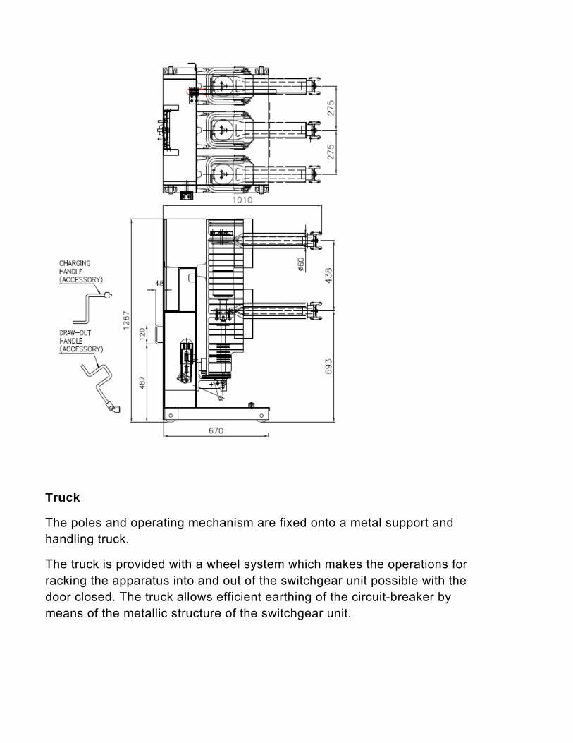
Truck
The poles and operating mechanism are fixed onto a metal support and handling truck.
The truck is provided with a wheel system which makes the operations for racking the apparatus into and out of the switchgear unit possible with the door closed. The truck allows efficient earthing of the circuit-breaker by means of the metallic structure of the switchgear unit.

Apparatus-operator interface
The front part of the circuit-breaker provides the user interface. It features the following equipment:
• ON pushbutton.
• OFF pushbutton.
• Operation counters.
• Indicator of the circuit-breaker open and closed state.
• Indicator of the charged or discharged state of the spring.
Standards
HYUNDAI vacuum circuit breakers meet IEC 62271-100, IEC 60056, and ANSI 37.09 standards.

Block / Resin type current transformers
The block type current transformers are epoxy resin insulated and used to supply the measurement devices and protection instruments. They conform to the IEC 60044-1 Standards. Current transformers are normally fitted on the load side of the apparatus compartment for measurement of the phase currents of the switchgear unit. Fitting on the supply side of the apparatus compartment is also possible (bus bar applications) for measuring the bus bar currents or for realising particular protection schemes.

Voltage transformers
The voltage transformers are of the epoxy resin insulated type and are used to supply measurement and protection devices. They are available for fixed assembly or for installation on removable and withdraw able trucks. They conform with the IEC 60044-2 Standards. These transformers can have one or two poles, with performance and precision classes suited to the functional requirements of the instruments connected to them. When they are installed on removable or withdraw able trucks they are fitted with medium voltage protection fuses. The withdraw able trucks also allow replacement of the fuses with the switchgear in service. Truck racking-out Fixed voltage transformers can be installed directly on the main bus bar system in a dedicated compartment (bus bar applications).

Single-line diagram of

Single-line diagram of the bus bar applications
Current transformers Voltage transformers Duct entry Earthing switch
Graphical symbols
Circuit-breaker Contactor Switch-disconnector Disconnector Isolating bar Socket and plug
Voltage transformers Current transformers
Fuse Earth Cable entry Bus bar ent
