mv switchgear secondary distribution - sebab · iec 62271-102 alternating current disconnectors and...
TRANSCRIPT
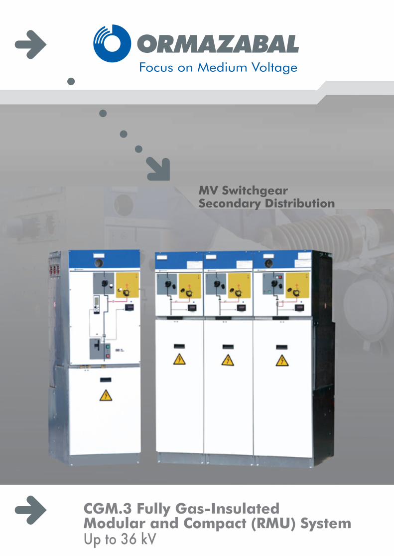
CGM.3 Fully Gas-InsulatedModular and Compact (RMU) SystemUp to 36 kV
MV SwitchgearSecondary Distribution
In view of the constant evolution in standards and design,the characteristics of the elements contained in this catalogueare subject to change without prior notification. Thesecharacteristics, as well as the availability of components,are subject to confirmation by Ormazabal's Technical -Commercial Department.
The quality of designed, manufactured and installedproducts is underpinned by the implementation andcertification of a quality management system, based onthe internat ional s tandard ISO 9001:2000.Our commitment to the environment is reaffirmed with theimplementation and certification of an environmentalmanagement system as laid down in international standardISO 14001.
Installation and Civil Engineering Works 23
Cable Connections 22
CGM.3 SystemContents
Environmental Information 24
Driving Mechanisms 20
ekorSYS family 19
Protection Functions 15
Reliability 15
Safety 14
Modularity: ORMALINK 13
Module Types 4
Applicable Standards 3
Main Characteristics 2
General Description 2
Spares and Accessories 24
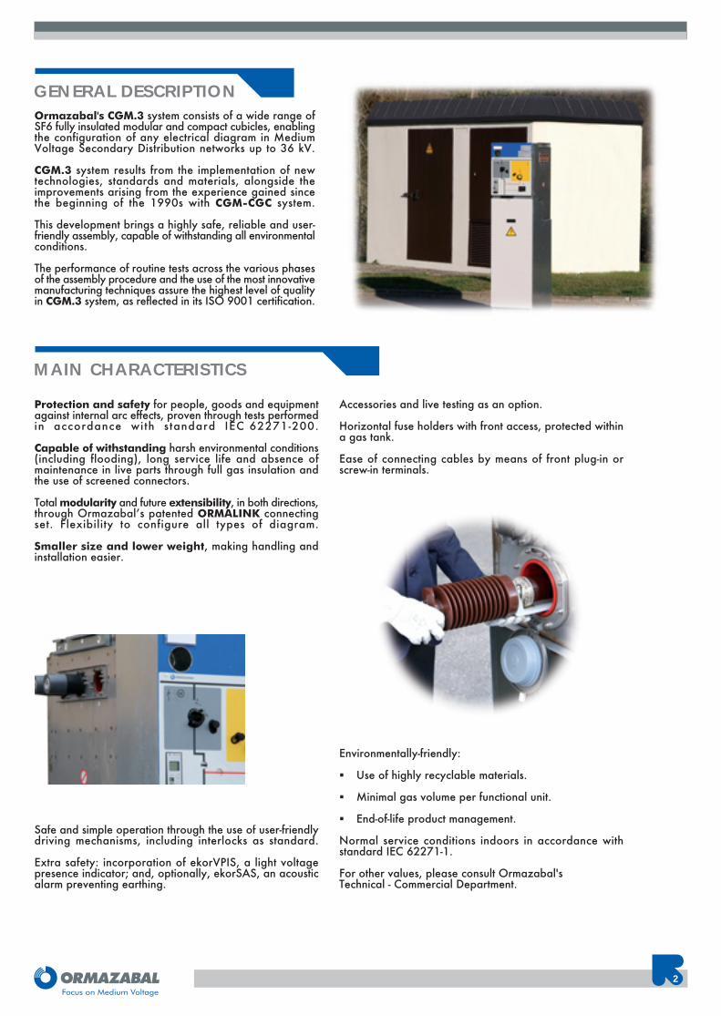
Ormazabal's CGM.3 system consists of a wide range ofSF6 fully insulated modular and compact cubicles, enablingthe configuration of any electrical diagram in MediumVoltage Secondary Distribution networks up to 36 kV.
CGM.3 system results from the implementation of newtechnologies, standards and materials, alongside theimprovements arising from the experience gained sincethe beginning of the 1990s with CGM-CGC system.
This development brings a highly safe, reliable and user-friendly assembly, capable of withstanding all environmentalconditions.
The performance of routine tests across the various phasesof the assembly procedure and the use of the most innovativemanufacturing techniques assure the highest level of qualityin CGM.3 system, as reflected in its ISO 9001 certification.
Protection and safety for people, goods and equipmentagainst internal arc effects, proven through tests performedin accordance with standard IEC 62271-200.
Capable of withstanding harsh environmental conditions(including flooding), long service life and absence ofmaintenance in live parts through full gas insulation andthe use of screened connectors.
Total modularity and future extensibility, in both directions,through Ormazabal’s patented ORMALINK connectingset. Flexibility to configure all types of diagram.
Smaller size and lower weight, making handling andinstallation easier.
Safe and simple operation through the use of user-friendlydriving mechanisms, including interlocks as standard.
Extra safety: incorporation of ekorVPIS, a light voltagepresence indicator; and, optionally, ekorSAS, an acousticalarm preventing earthing.
Accessories and live testing as an option.
Horizontal fuse holders with front access, protected withina gas tank.
Ease of connecting cables by means of front plug-in orscrew-in terminals.
Environmentally-friendly:
� Use of highly recyclable materials.
� Minimal gas volume per functional unit.
� End-of-life product management.
Normal service conditions indoors in accordance withstandard IEC 62271-1.
For other values, please consult Ormazabal'sTechnical - Commercial Department.
2
GENERAL DESCRIPTION
MAIN CHARACTERISTICS
CGM.3 system meets the following standards:
IEC 62271-001Common specifications for high-voltage switchgear andcontrolgear standards.
IEC 62271-200Alternating current metal-enclosed switchgear andcontrolgear for rated voltages above 1 kV and up to andincluding 52 kV.
IEC 60265-1High-voltage switches. Part 1: Switches for rated voltagesabove 1 kV and less than 52 kV.
IEC 62271-102Alternating current disconnectors and earthing switches.
IEC 62271-105High voltage alternating current switch-fuse combinations.
IEC 62271-100High voltage alternating current circuit-breakers.
IEC 60255Electrical relays.
IEC 60529Degrees of protection provided by enclosures.
IEC 61958Voltage presence indicating systems.
CGM.3 system exceeds the immersion test at a pressureof 3 metres of water column, 24 hours at rated voltageand power frequency insulation test.
3
CGM.3 System
STANDARDS
APPLICATIONS
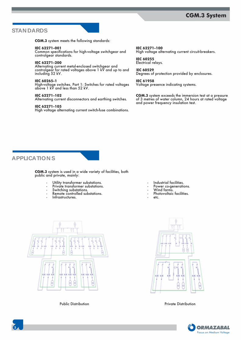
CGM.3 system is used in a wide variety of facilities, bothpublic and private, mainly:
- Utility transformer substations.- Private transformer substations.- Switching substations.- Remote controlled substations.- Infrastructures.
- Industrial facilities.- Power co-generations.- Wind farms.- Photovoltaic facilities.- etc.
Public Distribution Private Distribution
4
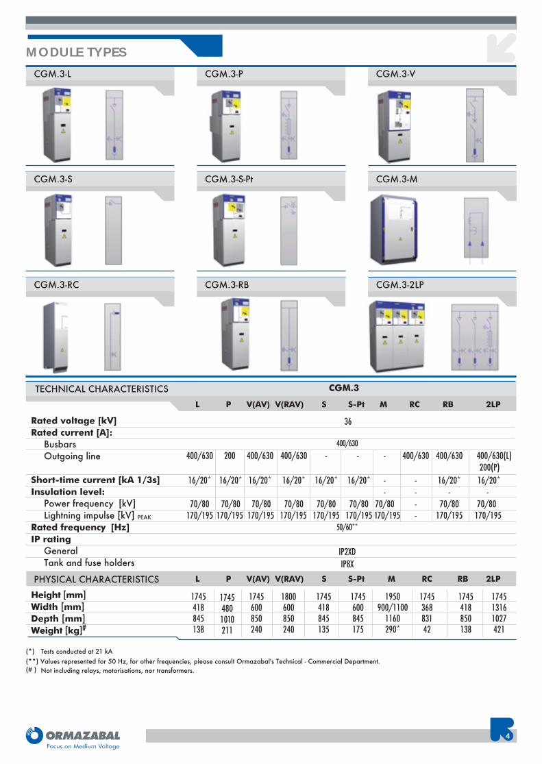
(*) Tests conducted at 21 kA(**) Values represented for 50 Hz, for other frequencies, please consult Ormazabal's Technical - Commercial Department.(# ) Not including relays, motorisations, nor transformers.
36Rated voltage [kV]Rated current [A]:
BusbarsOutgoing line
Short-time current [kA 1/3s]Insulation level:
Power frequency [kV]Lightning impulse [kV] PEAK
Rated frequency [Hz]IP rating
GeneralTank and fuse holders
L P V(AV) V(RAV) S S-Pt M RC RB 2LP
400/630
IP2XDIP8X
TECHNICAL CHARACTERISTICS CGM.3
400/630 200 400/630 400/630 - - - 400/630 400/630 400/630(L)
16/20* 16/20* 16/20* 16/20* 16/20* 16/20* - - 16/20* 16/20* - - - -
70/80 70/80 70/80 70/80 70/80 70/80 70/80 - 70/80 70/80170/195 170/195 170/195 170/195 170/195 170/195 170/195 - 170/195 170/195
50/60**
PHYSICAL CHARACTERISTICS
Height [mm]Width [mm]Depth [mm]Weight [kg]#
1745418845138
17454801010211
1745600850240
1745418845135
1745600845175
1950900/1100
1160290*
174536883142
1745418850138
174513161027421
L P V(AV) V(RAV) S S-Pt M RC RB 2LP
1800600850240
MODULE TYPESCGM.3-L CGM.3-P CGM.3-V
CGM.3-S CGM.3-S-Pt CGM.3-M
CGM.3-RC CGM.3-RB CGM.3-2LP
200(P)
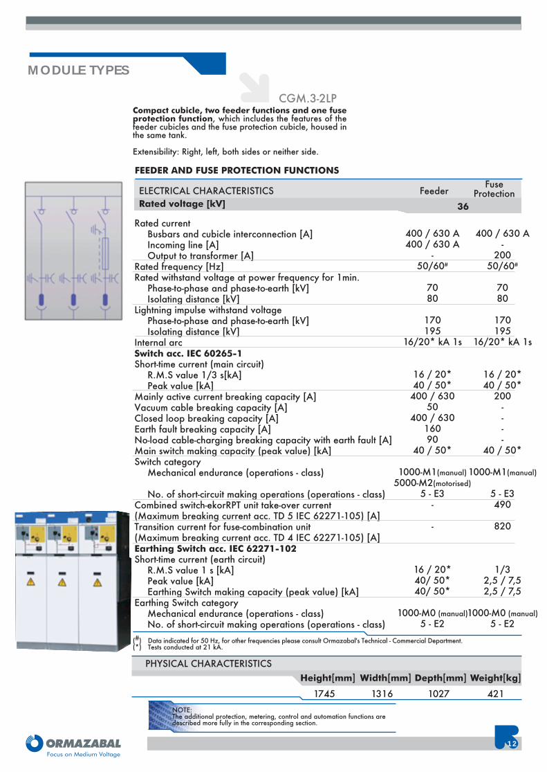
NOTE:The additional protection, metering, control and automation functions aredescribed more fully in the corresponding section.
5
CGM.3 System
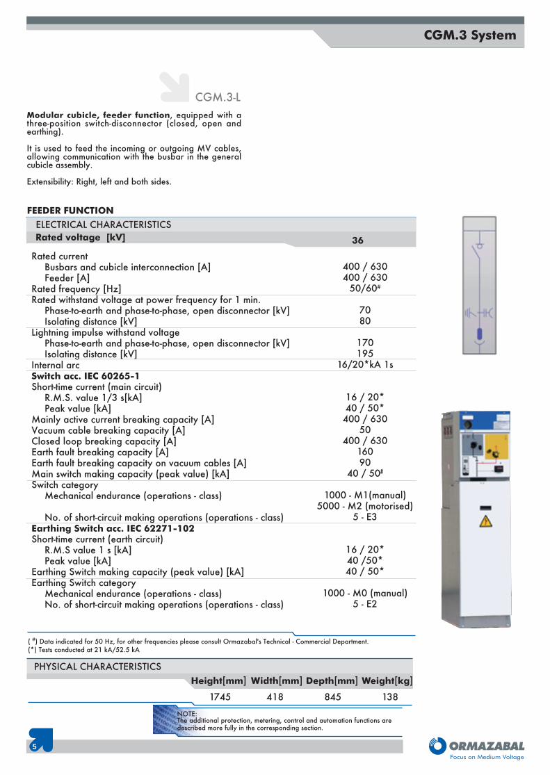
Modular cubicle, feeder function, equipped with athree-position switch-disconnector (closed, open andearthing).
It is used to feed the incoming or outgoing MV cables,allowing communication with the busbar in the generalcubicle assembly.
Extensibility: Right, left and both sides.
CGM.3-L
1745
PHYSICAL CHARACTERISTICS
418 845 138
Height[mm] Width[mm] Depth[mm] Weight[kg]
FEEDER FUNCTION
Rated currentBusbars and cubicle interconnection [A]Feeder [A]
Rated frequency [Hz]Rated withstand voltage at power frequency for 1 min.
Phase-to-earth and phase-to-phase, open disconnector [kV]Isolating distance [kV]
Lightning impulse withstand voltagePhase-to-earth and phase-to-phase, open disconnector [kV]Isolating distance [kV]
Internal arcSwitch acc. IEC 60265-1Short-time current (main circuit)
R.M.S. value 1/3 s[kA]Peak value [kA]
Mainly active current breaking capacity [A]Vacuum cable breaking capacity [A]Closed loop breaking capacity [A]Earth fault breaking capacity [A]Earth fault breaking capacity on vacuum cables [A]Main switch making capacity (peak value) [kA]Switch category
Mechanical endurance (operations - class)
No. of short-circuit making operations (operations - class)Earthing Switch acc. IEC 62271-102Short-time current (earth circuit)
R.M.S value 1 s [kA]Peak value [kA]
Earthing Switch making capacity (peak value) [kA]Earthing Switch category
Mechanical endurance (operations - class)No. of short-circuit making operations (operations - class)
36
( #) Data indicated for 50 Hz, for other frequencies please consult Ormazabal's Technical - Commercial Department.(*) Tests conducted at 21 kA/52.5 kA
400 / 630400 / 630
50/60#
7080
170195
16/20*kA 1s
16 / 20*40 / 50*400 / 630
50400 / 630
16090
40 / 50#
1000 - M1(manual)5000 - M2 (motorised)
5 - E3
16 / 20*40 /50*40 / 50*
1000 - M0 (manual)5 - E2
ELECTRICAL CHARACTERISTICSRated voltage [kV]
NOTE:The additional protection, metering, control and automation functions aredescribed more fully in the corresponding section.
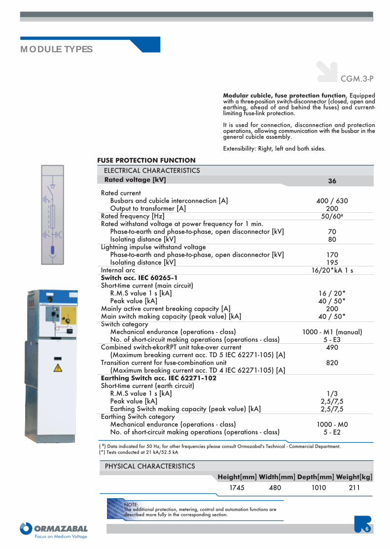
CGM.3-P
6
( #) Data indicated for 50 Hz, for other frequencies please consult Ormazabal's Technical - Commercial Department.(*) Tests conducted at 21 kA/52.5 kA
Rated currentBusbars and cubicle interconnection [A]Output to transformer [A]
Rated frequency [Hz]Rated withstand voltage at power frequency for 1 min.
Phase-to-earth and phase-to-phase, open disconnector [kV]Isolating distance [kV]
Lightning impulse withstand voltagePhase-to-earth and phase-to-phase, open disconnector [kV]Isolating distance [kV]
Internal arcSwitch acc. IEC 60265-1Short-time current (main circuit)
R.M.S value 1 s [kA]Peak value [kA]
Mainly active current breaking capacity [A]Main switch making capacity (peak value) [kA]Switch category
Mechanical endurance (operations - class)No. of short-circuit making operations (operations - class)
Combined switch-ekorRPT unit take-over current(Maximum breaking current acc. TD 5 IEC 62271-105) [A]
Transition current for fuse-combination unit(Maximum breaking current acc. TD 4 IEC 62271-105) [A]
Earthing Switch acc. IEC 62271-102Short-time current (earth circuit)
R.M.S value 1 s [kA]Peak value [kA]Earthing Switch making capacity (peak value) [kA]
Earthing Switch categoryMechanical endurance (operations - class)No. of short-circuit making operations (operations - class)
36
ELECTRICAL CHARACTERISTICS
400 / 630200
50/60#
7080
170195
16/20*kA 1 s
16 / 20*40 / 50*
20040 / 50*
1000 - M1 (manual)5 - E3490
820
1/32,5/7,52,5/7,5
1000 - M05 - E2
FUSE PROTECTION FUNCTION
1745
PHYSICAL CHARACTERISTICS
480 1010 211Height[mm] Width[mm] Depth[mm] Weight[kg]
MODULE TYPES
Modular cubicle, fuse protection function, Equippedwith a three-position switch-disconnector (closed, open andearthing, ahead of and behind the fuses) and current-limiting fuse-link protection.
It is used for connection, disconnection and protectionoperations, allowing communication with the busbar in thegeneral cubicle assembly.
Extensibility: Right, left and both sides.
Rated voltage [kV]
NOTE:The additional protection, metering, control and automation functions aredescribed more fully in the corresponding section.
7
CGM.3 System
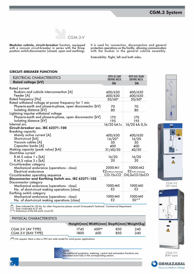
Modular cubicle, circuit-breaker function, equippedwith a vacuum circuit-breaker in series with the three-position switch-disconnector (closed, open and earthing).
It is used for connection, disconnection and generalprotection operations on the facility, allowing communicationwith the busbar in the general cubicle assembly.
Extensibility: Right, left and both sides.
CGM.3-V
17451800
600##
600850850
240240
PHYSICAL CHARACTERISTICSHeight[mm] Width[mm] Depth[mm] Weight[kg]
CGM.3-V (AV TYPE)CGM.3-V (RAV TYPE)
CGM.3-V(AV type)
CGM.3-V(RAV type)
CIRCUIT-BREAKER FUNCTION
Rated currentBusbars and cubicle interconnection [A]Feeder [A]
Rated frequency [Hz]Rated withstand voltage at power frequency for 1 min.
Phase-to-earth and phase-to-phase, open disconnector [kV]Isolating distance [kV]
Lightning impulse withstand voltagePhase-to-earth and phase-to-phase, open disconnector [kV]Isolating distance [kV]
Internal arcCircuit-breaker acc. IEC 62271-100Breaking capacity
Mainly active current [A]Short-circuit [kA]Vacuum cables [A]Capacitor banks [A]
Making capacity (peak value) [kA]Short-time current
R.M.S value 1 s [kA]R.M.S value 3 s [kA]
Circuit-breaker categoryMechanical endurance (operations - class)Electrical endurance
Circuit-breaker operating sequenceDisconnector and Earthing Switch acc. IEC 62271-102Disconnector category
Mechanical endurance (operations - class)No. of short-circuit making operations (class)
Earthing switch categoryMechanical endurance (operations - class)No. of short-circuit making operations (class)
36
(#) Data indicated for 50 Hz, for other frequencies please consult Ormazabal's Technical - Commercial Department.(*) Tests conducted at 21 kA(**) Endurance of the full earth circuit E2
400/630400/63050/60#
7080
170195
16/20 kA1s
400/63016/20*
50400
31/40/50
16/2020
2000-M1E2(without reclosing)
CO-15s-CO
1000-M0E2
1000-M0E2
ELECTRICAL CHARACTERISTICS36
WITH AV/AMVDRIVING MECH.
WITH RAV/RAMVDRIVING MECH.
400/630400/63050/60#
7080
170195
16/20 kA 0,5s
400/63016/20
50400
40/50
16/2020
10000-M2E2(with reclosing)
O-0,3s-CO-15s-CO
1000-M0E2
1000-M0E0**
Rated voltage [kV]
(##) On request, there is also a 595 mm wide model for wind power applications.
NOTE:The additional protection, metering, control and automation functions aredescribed more fully in the corresponding section.
8
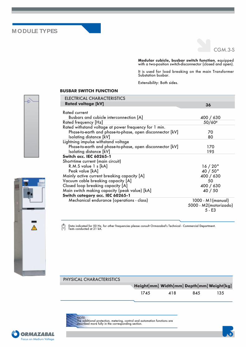
CGM.3-S
MODULE TYPES
1745 418 845 135
PHYSICAL CHARACTERISTICS
Modular cubicle, busbar switch function, equippedwith a two-position switch-disconnector (closed and open).
It is used for load breaking on the main TransformerSubstation busbar.
Extensibility: Both sides.
Height[mm] Width[mm] Depth[mm] Weight[kg]
BUSBAR SWITCH FUNCTION
Rated currentBusbars and cubicle interconnection [A]
Rated frequency [Hz]Rated withstand voltage at power frequency for 1 min.
Phase-to-earth and phase-to-phase, open disconnector [kV]Isolating distance [kV]
Lightning impulse withstand voltagePhase-to-earth and phase-to-phase, open disconnector [kV]Isolating distance [kV]
Switch acc. IEC 60265-1Short-time current (main circuit)
R.M.S value 1 s [kA]Peak value [kA]
Mainly active current breaking capacity [A]Vacuum cable breaking capacity [A]Closed loop breaking capacity [A]Main switch making capacity (peak value) [kA]Switch category acc. IEC 60265-1
Mechanical endurance (operations - class)
36
(#) Data indicated for 50 Hz, for other frequencies please consult Ormazabal's Technical - Commercial Department.(*) Tests conducted at 21 kA.
400 / 63050/60#
7080
170195
16 / 20*40 / 50*400 / 630
50400 / 63040 / 50
1000 - M1(manual)5000 - M2(motorizado)
5 - E3
ELECTRICAL CHARACTERISTICSRated voltage [kV]
NOTE:The additional protection, metering, control and automation functions aredescribed more fully in the corresponding section.
9
CGM.3 System
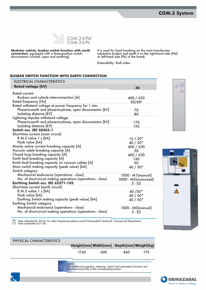
BUSBAR SWITCH FUNCTION WITH EARTH CONNECTION
Rated currentBusbars and cubicle interconnection [A]
Rated frequency [Hz]Rated withstand voltage at power frequency for 1 min.
Phase-to-earth and phase-to-phase, open disconnector [kV]Isolating distance [kV]
Lightning impulse withstand voltagePhase-to-earth and phase-to-phase, open disconnector [kV]Isolating distance [kV]
Switch acc. IEC 60265-1Short-time current (main circuit)
R.M.S value 1 s [kA]Peak value [kA]
Mainly active current breaking capacity [A]Vacuum cable breaking capacity [A]Closed loop breaking capacity [A]Earth fault breaking capacity [A]Earth fault breaking capacity on vacuum cables [A]Main switch making capacity (peak value) [kA]Switch category
Mechanical endurance (operations - class)No. of short-circuit making operations (operations - class)
Earthing Switch acc. IEC 62271-102Short-time current (earth circuit)
R.M.S value 1 s [kA]Peak value [kA]Earthing Switch making capacity (peak value) [kA]
Earthing Switch categoryMechanical endurance (operations - class)No. of short-circuit making operations (operations - class)
ELECTRICAL CHARACTERISTICS
Modular cubicle, busbar switch function with earthconnection, equipped with a three-position switch-disconnector (closed, open and earthing).
It is used for load breaking on the main transformersubstation busbar and earth it on the right-hand side (Ptd)or left-hand side (Pti) of the break.
Extensibility: Both sides.
CGM.3-S-PtdCGM.3-S-Pti
36
400 / 63050/60#
7080
170195
16 / 20*40 / 50*400 / 630
50400 / 630
16090
40 / 50*
1000 - M1(manual)5000 - M2(motorised)
5 - E3
40 /50*40 / 50*40 / 50*
1000 - M0(manual)5 - E2
(#) Data indicated for 50 Hz, for other frequencies please consult Ormazabal's Technical - Commercial Department.(*) Tests conducted at 21 kA.
1745 600 845 175
PHYSICAL CHARACTERISTICSHeight[mm] Width[mm] Depth[mm] Weight[kg]
Rated voltage [kV]
10
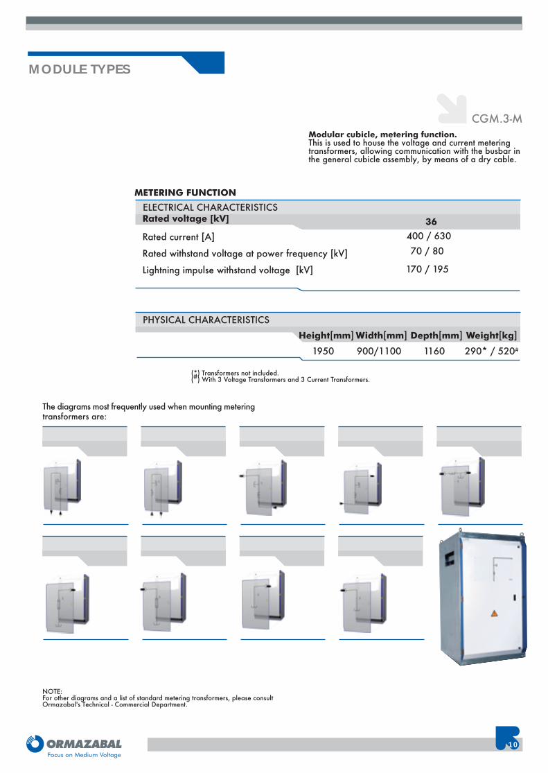
CGM.3-M
The diagrams most frequently used when mounting meteringtransformers are:
MODULE TYPES
PHYSICAL CHARACTERISTICSHeight[mm] Width[mm] Depth[mm] Weight[kg]
1950 900/1100 1160 290* / 520#
Modular cubicle, metering function.This is used to house the voltage and current meteringtransformers, allowing communication with the busbar inthe general cubicle assembly, by means of a dry cable.
NOTE:For other diagrams and a list of standard metering transformers, please consultOrmazabal's Technical - Commercial Department.
(*) Transformers not included.(#) With 3 Voltage Transformers and 3 Current Transformers.
ELECTRICAL CHARACTERISTICS36
METERING FUNCTION
400 / 630
Rated voltage [kV]
Rated current [A]
Rated withstand voltage at power frequency [kV]
Lightning impulse withstand voltage [kV]
70 / 80
170 / 195
11
CGM.3 System
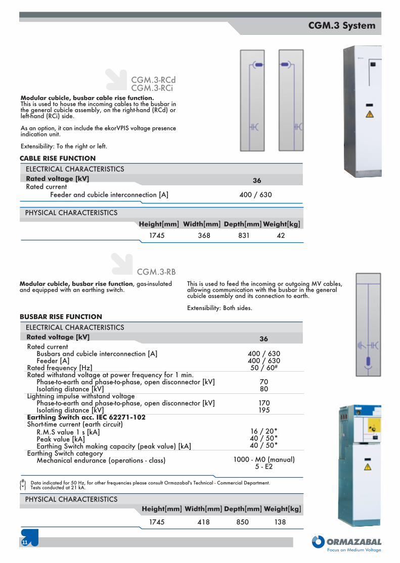
Modular cubicle, busbar cable rise function.This is used to house the incoming cables to the busbar inthe general cubicle assembly, on the right-hand (RCd) orleft-hand (RCi) side.
As an option, it can include the ekorVPIS voltage presenceindication unit.
Extensibility: To the right or left.
CGM.3-RCdCGM.3-RCi
Modular cubicle, busbar rise function, gas-insulatedand equipped with an earthing switch.
This is used to feed the incoming or outgoing MV cables,allowing communication with the busbar in the generalcubicle assembly and its connection to earth.
Extensibility: Both sides.
CGM.3-RB
PHYSICAL CHARACTERISTICSHeight[mm] Width[mm] Depth[mm] Weight[kg]
1745 368 831 42
PHYSICAL CHARACTERISTICS
1745 418 850 138
Height[mm] Width[mm] Depth[mm] Weight[kg]
(#) Data indicated for 50 Hz, for other frequencies please consult Ormazabal's Technical - Commercial Department.(*) Tests conducted at 21 kA.
400 / 630
ELECTRICAL CHARACTERISTICS
36
CABLE RISE FUNCTION
Rated voltage [kV]Rated current
Feeder and cubicle interconnection [A]
Rated currentBusbars and cubicle interconnection [A]Feeder [A]
Rated frequency [Hz]Rated withstand voltage at power frequency for 1 min.
Phase-to-earth and phase-to-phase, open disconnector [kV]Isolating distance [kV]
Lightning impulse withstand voltagePhase-to-earth and phase-to-phase, open disconnector [kV]Isolating distance [kV]
Earthing Switch acc. IEC 62271-102Short-time current (earth circuit)
R.M.S value 1 s [kA]Peak value [kA]Earthing Switch making capacity (peak value) [kA]
Earthing Switch categoryMechanical endurance (operations - class)
400 / 630400 / 63050 / 60#
7080
170195
16 / 20*40 / 50*40 / 50*
1000 - M0 (manual)5 - E2
ELECTRICAL CHARACTERISTICS
36
BUSBAR RISE FUNCTION
Rated voltage [kV]
NOTE:The additional protection, metering, control and automation functions aredescribed more fully in the corresponding section.
12
Compact cubicle, two feeder functions and one fuseprotection function, which includes the features of thefeeder cubicles and the fuse protection cubicle, housed inthe same tank.
Extensibility: Right, left, both sides or neither side.
CGM.3-2LP
MODULE TYPES
1745 1316 1027 421
PHYSICAL CHARACTERISTICS
FEEDER AND FUSE PROTECTION FUNCTIONS
(#) Data indicated for 50 Hz, for other frequencies please consult Ormazabal's Technical - Commercial Department.(*) Tests conducted at 21 kA.
Rated currentBusbars and cubicle interconnection [A]Incoming line [A]Output to transformer [A]
Rated frequency [Hz]Rated withstand voltage at power frequency for 1min.
Phase-to-phase and phase-to-earth [kV]Isolating distance [kV]
Lightning impulse withstand voltagePhase-to-phase and phase-to-earth [kV]Isolating distance [kV]
Internal arcSwitch acc. IEC 60265-1Short-time current (main circuit)
R.M.S value 1/3 s[kA]Peak value [kA]
Mainly active current breaking capacity [A]Vacuum cable breaking capacity [A]Closed loop breaking capacity [A]Earth fault breaking capacity [A]No-load cable-charging breaking capacity with earth fault [A]Main switch making capacity (peak value) [kA]Switch category
Mechanical endurance (operations - class)
No. of short-circuit making operations (operations - class)Combined switch-ekorRPT unit take-over current(Maximum breaking current acc. TD 5 IEC 62271-105) [A]Transition current for fuse-combination unit(Maximum breaking current acc. TD 4 IEC 62271-105) [A]Earthing Switch acc. IEC 62271-102Short-time current (earth circuit)
R.M.S value 1 s [kA]Peak value [kA]Earthing Switch making capacity (peak value) [kA]
Earthing Switch categoryMechanical endurance (operations - class)No. of short-circuit making operations (operations - class)
ELECTRICAL CHARACTERISTICS
400 / 630 A400 / 630 A
-50/60#
7080
170195
16/20* kA 1s
16 / 20*40 / 50*400 / 630
50400 / 630
16090
40 / 50*
1000-M1(manual)5000-M2(motorised)
5 - E3-
-
16 / 20*40/ 50*40/ 50*
1000-M0 (manual)5 - E2
FeederFuse
Protection36
Height[mm] Width[mm] Depth[mm] Weight[kg]
400 / 630 A-
20050/60#
7080
170195
16/20* kA 1s
16 / 20*40 / 50*
200----
40 / 50*
1000-M1(manual)
5 - E3490
820
1/32,5 / 7,52,5 / 7,5
1000-M0 (manual)5 - E2
Rated voltage [kV]
13
MODULARITY. ORMALINK
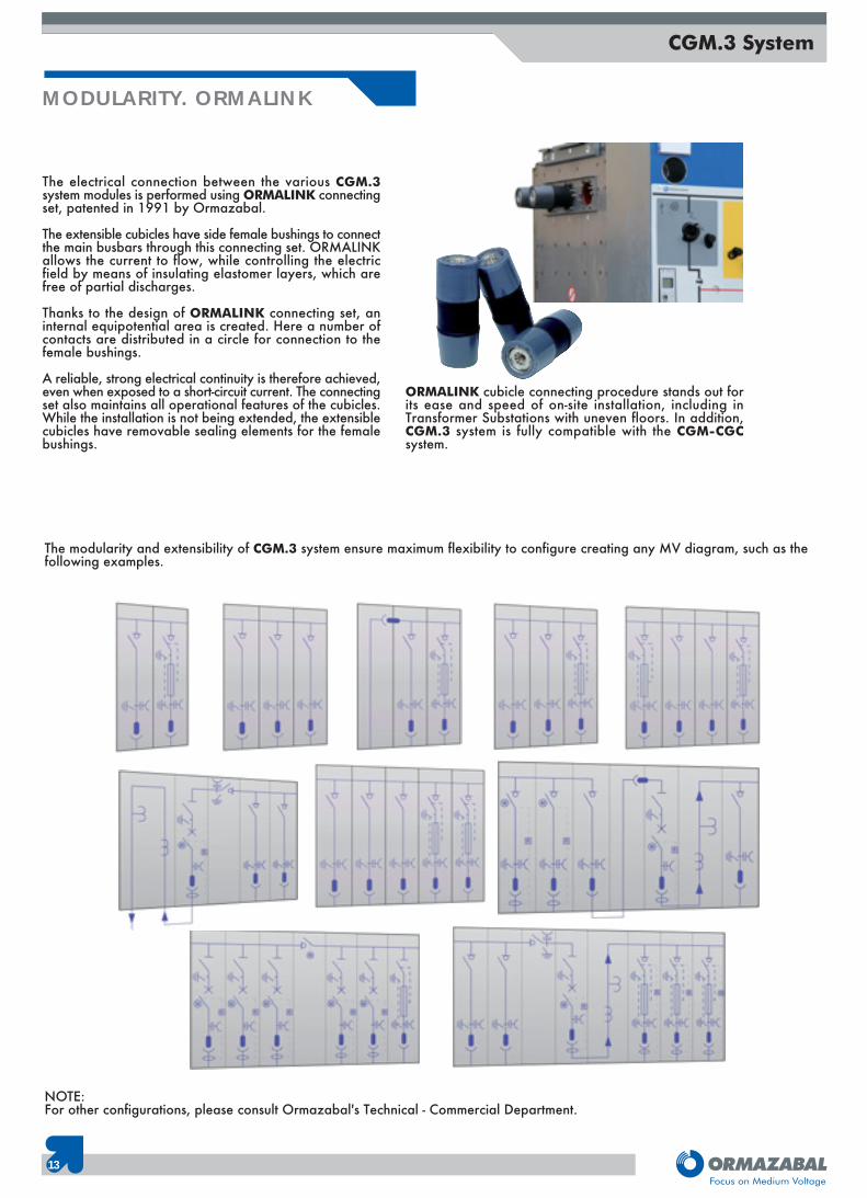
The electrical connection between the various CGM.3system modules is performed using ORMALINK connectingset, patented in 1991 by Ormazabal.
The extensible cubicles have side female bushings to connectthe main busbars through this connecting set. ORMALINKallows the current to flow, while controlling the electricfield by means of insulating elastomer layers, which arefree of partial discharges.
Thanks to the design of ORMALINK connecting set, aninternal equipotential area is created. Here a number ofcontacts are distributed in a circle for connection to thefemale bushings.
A reliable, strong electrical continuity is therefore achieved,even when exposed to a short-circuit current. The connectingset also maintains all operational features of the cubicles.While the installation is not being extended, the extensiblecubicles have removable sealing elements for the femalebushings.
ORMALINK cubicle connecting procedure stands out forits ease and speed of on-site installation, including inTransformer Substations with uneven floors. In addition,CGM.3 system is fully compatible with the CGM-CGCsystem.
The modularity and extensibility of CGM.3 system ensure maximum flexibility to configure creating any MV diagram, such as thefollowing examples.
NOTE:For other configurations, please consult Ormazabal's Technical - Commercial Department.
CGM.3 System
14
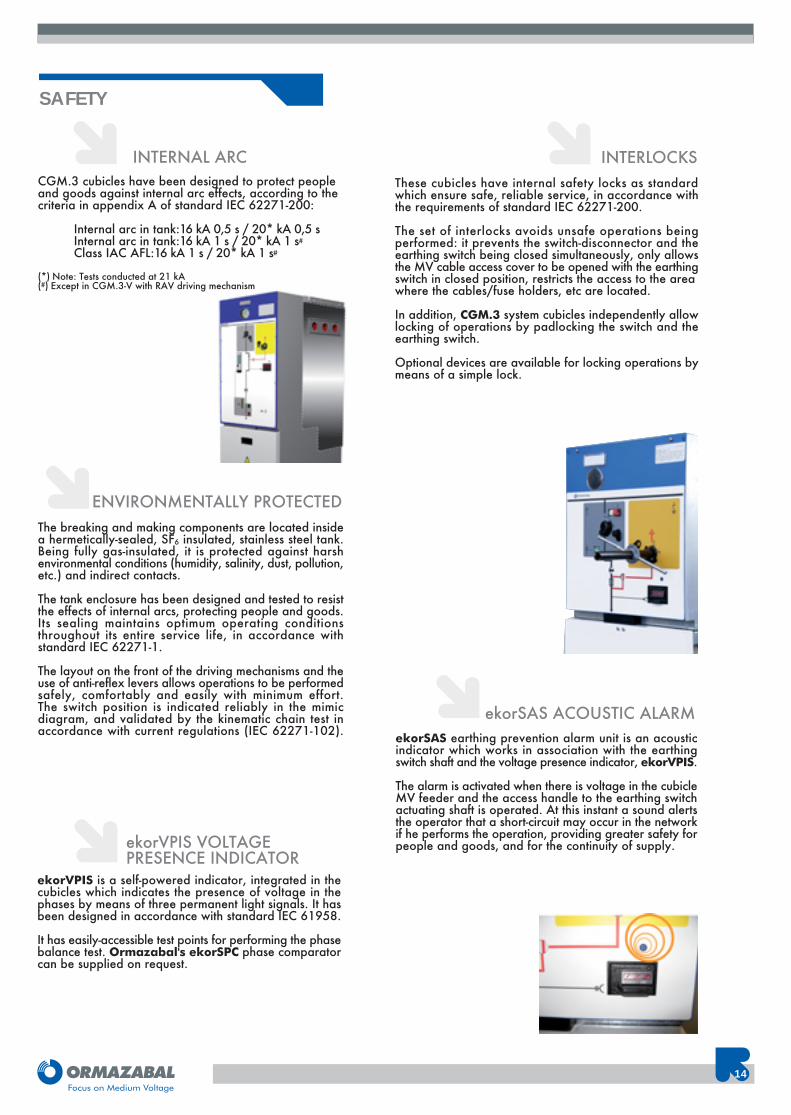
INTERNAL ARC
ENVIRONMENTALLY PROTECTEDThe breaking and making components are located insidea hermetically-sealed, SF6 insulated, stainless steel tank.Being fully gas-insulated, it is protected against harshenvironmental conditions (humidity, salinity, dust, pollution,etc.) and indirect contacts.
The tank enclosure has been designed and tested to resistthe effects of internal arcs, protecting people and goods.Its sealing maintains optimum operating conditionsthroughout its entire service life, in accordance withstandard IEC 62271-1.
The layout on the front of the driving mechanisms and theuse of anti-reflex levers allows operations to be performedsafely, comfortably and easily with minimum effort.The switch position is indicated reliably in the mimicdiagram, and validated by the kinematic chain test inaccordance with current regulations (IEC 62271-102).
INTERLOCKSThese cubicles have internal safety locks as standardwhich ensure safe, reliable service, in accordance withthe requirements of standard IEC 62271-200.
The set of interlocks avoids unsafe operations beingperformed: it prevents the switch-disconnector and theearthing switch being closed simultaneously, only allowsthe MV cable access cover to be opened with the earthingswitch in closed position, restricts the access to the areawhere the cables/fuse holders, etc are located.
In addition, CGM.3 system cubicles independently allowlocking of operations by padlocking the switch and theearthing switch.
Optional devices are available for locking operations bymeans of a simple lock.
ekorVPIS VOLTAGEPRESENCE INDICATOR
ekorVPIS is a self-powered indicator, integrated in thecubicles which indicates the presence of voltage in thephases by means of three permanent light signals. It hasbeen designed in accordance with standard IEC 61958.
It has easily-accessible test points for performing the phasebalance test. Ormazabal's ekorSPC phase comparatorcan be supplied on request.
ekorSAS ACOUSTIC ALARMekorSAS earthing prevention alarm unit is an acousticindicator which works in association with the earthingswitch shaft and the voltage presence indicator, ekorVPIS.
The alarm is activated when there is voltage in the cubicleMV feeder and the access handle to the earthing switchactuating shaft is operated. At this instant a sound alertsthe operator that a short-circuit may occur in the networkif he performs the operation, providing greater safety forpeople and goods, and for the continuity of supply.
SAFETY
CGM.3 cubicles have been designed to protect peopleand goods against internal arc effects, according to thecriteria in appendix A of standard IEC 62271-200:
Internal arc in tank:16 kA 0,5 s / 20* kA 0,5 sInternal arc in tank:16 kA 1 s / 20* kA 1 s#
Class IAC AFL:16 kA 1 s / 20* kA 1 s#
(*) Note: Tests conducted at 21 kA(#) Except in CGM.3-V with RAV driving mechanism
15
CGM.3 System
RELIABILITY
CGM.3 system cubicles contribute to improving electricaldistribution in Medium Voltage networks up to 36 kV bymeans of:
- Testing, including routine tests and tracking, of all equipment in the factory.
- Interlocks between the switching and breaking components.
- Visual indication of the switchgear position in the mimic diagram, validated by the kinematic chain testin accordance with current regulations(IEC 62271-102).
- High anti-corrosive levels, achieved by the use of new materials.
- Accessories and live testing as an option, in the driving mechanism area.
- Ease of connecting cables, by means of plug-in or screw-in terminals.
PROTECTION FUNCTIONS
WITH FUSES
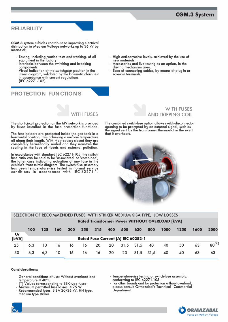
The short-circuit protection on the MV network is providedby fuses installed in the fuse protection functions.
The fuse holders are protected inside the gas tank in ahorizontal position, thus achieving a uniform temperatureall along their length. With their covers closed they arecompletely hermetically sealed and they maintain thissealing in the face of floods and external pollution.
In accordance with standard IEC 62271-105, the switch-fuse ratio can be said to be 'associated' or 'combined',the latter case indicating actuation of any fuse in thecubicle's front mimic diagram. The switch-fuse assemblyhas been temperature-rise tested in normal servicecondit ions in accordance with IEC 62271-1.
Considerations:
- General conditions of use: Without overload and temperature < 40ºC
- [*] Values corresponding to SSK-type fuses- Maximum permitted fuse losses: < 75 W- Recommended fuses: SIBA 20/36 kV, HH type,
medium type striker
- Temperature-rise testing of switch-fuse assembly, conforming to IEC 62271-105.
- For other brands and for protection without overload,please consult Ormazabal's Technical - CommercialDepartment.
The combined switch-fuse option allows switch-disconnectoropening to be prompted by an external signal, such asthe signal sent by the transformer thermostat in the eventthat it overheats.
WITH FUSESAND TRIPPING COIL
Rated Transformer Power WITHOUT OVERLOAD [kVA]
SELECTION OF RECOMMENDED FUSES, WITH STRIKER MEDIUM SIBA TYPE, LOW LOSSES
Rated Fuse Current [A] IEC 60282-1Ur
[kVA]
100 125 160 200 250 315 400 500 630 800 1000 1250 1600 2000
6,3 10 16 16 16 20 20 31,5 40 40 50 63 80[*]
6,3 6,3 10 16 16 16 20 20 31,5 31,5 40 40 63 63
25
30
31,5
16
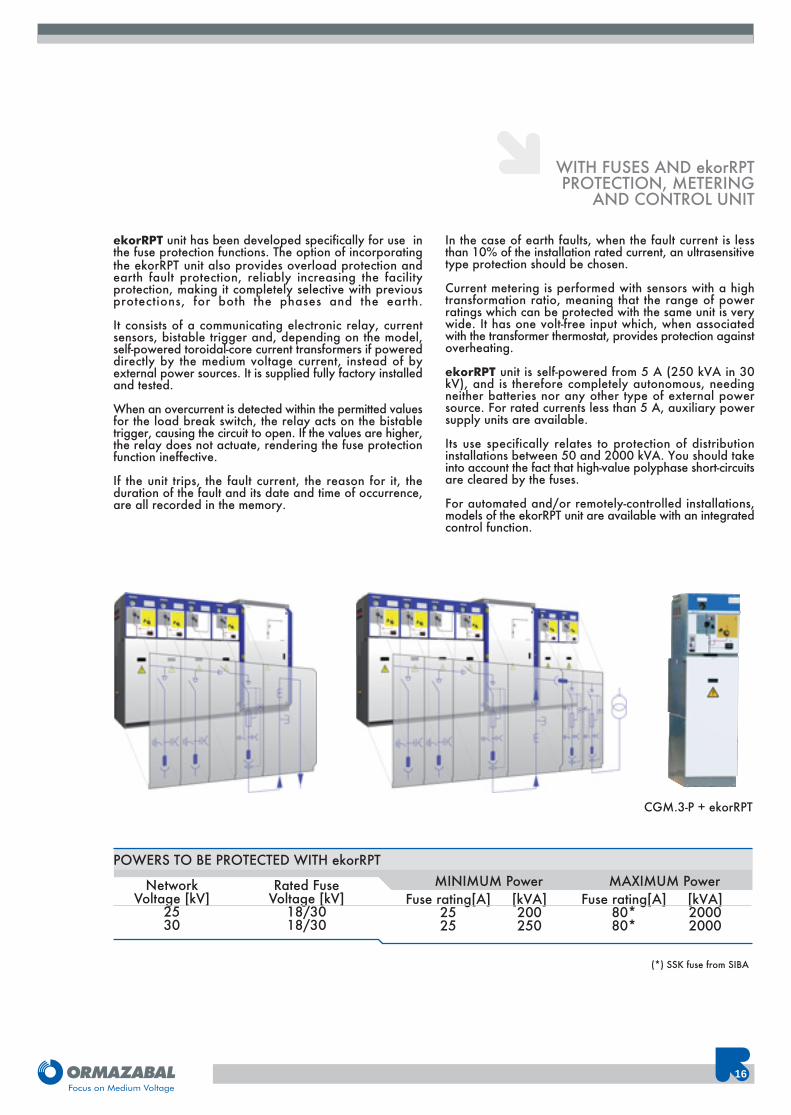
ekorRPT unit has been developed specifically for use inthe fuse protection functions. The option of incorporatingthe ekorRPT unit also provides overload protection andearth fault protection, reliably increasing the facilityprotection, making it completely selective with previousprotections, for both the phases and the earth.
It consists of a communicating electronic relay, currentsensors, bistable trigger and, depending on the model,self-powered toroidal-core current transformers if powereddirectly by the medium voltage current, instead of byexternal power sources. It is supplied fully factory installedand tested.
When an overcurrent is detected within the permitted valuesfor the load break switch, the relay acts on the bistabletrigger, causing the circuit to open. If the values are higher,the relay does not actuate, rendering the fuse protectionfunction ineffective.
If the unit trips, the fault current, the reason for it, theduration of the fault and its date and time of occurrence,are all recorded in the memory.
In the case of earth faults, when the fault current is lessthan 10% of the installation rated current, an ultrasensitivetype protection should be chosen.
Current metering is performed with sensors with a hightransformation ratio, meaning that the range of powerratings which can be protected with the same unit is verywide. It has one volt-free input which, when associatedwith the transformer thermostat, provides protection againstoverheating.
ekorRPT unit is self-powered from 5 A (250 kVA in 30kV), and is therefore completely autonomous, needingneither batteries nor any other type of external powersource. For rated currents less than 5 A, auxiliary powersupply units are available.
Its use specifically relates to protection of distributioninstallations between 50 and 2000 kVA. You should takeinto account the fact that high-value polyphase short-circuitsare cleared by the fuses.
For automated and/or remotely-controlled installations,models of the ekorRPT unit are available with an integratedcontrol function.
WITH FUSES AND ekorRPTPROTECTION, METERING
AND CONTROL UNIT
(*) SSK fuse from SIBA
NetworkVoltage [kV]
2530
MINIMUM PowerPOWERS TO BE PROTECTED WITH ekorRPT
Fuse rating[A]2525
Rated FuseVoltage [kV]
18/3018/30
[kVA]200250
MAXIMUM PowerFuse rating[A]
80*80*
[kVA]20002000
CGM.3-P + ekorRPT
17
CGM.3 System
Networkvoltage[kV]
2530
MINIMUM PowerPOWERS TO BE PROTECTED with ekorRPG
[kVA]200250
MAXIMUM Power[kVA]2000025000
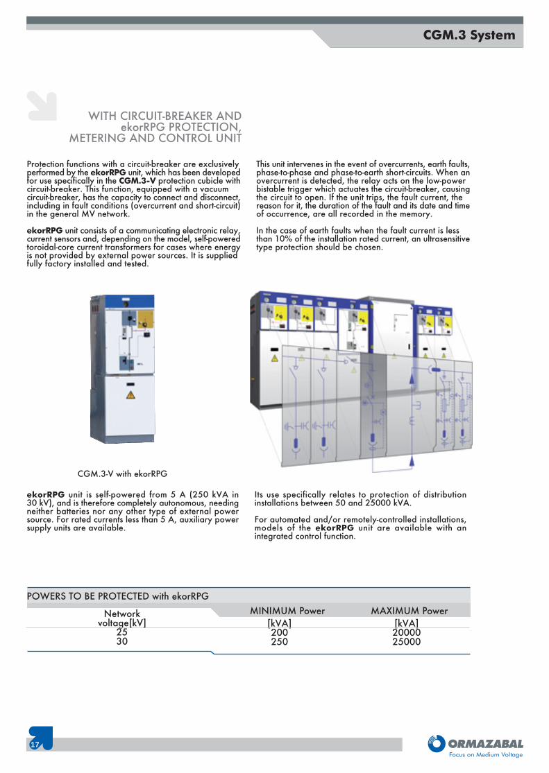
Protection functions with a circuit-breaker are exclusivelyperformed by the ekorRPG unit, which has been developedfor use specifically in the CGM.3-V protection cubicle withcircuit-breaker. This function, equipped with a vacuumcircuit-breaker, has the capacity to connect and disconnect,including in fault conditions (overcurrent and short-circuit)in the general MV network.
ekorRPG unit consists of a communicating electronic relay,current sensors and, depending on the model, self-poweredtoroidal-core current transformers for cases where energyis not provided by external power sources. It is suppliedfully factory installed and tested.
This unit intervenes in the event of overcurrents, earth faults,phase-to-phase and phase-to-earth short-circuits. When anovercurrent is detected, the relay acts on the low-powerbistable trigger which actuates the circuit-breaker, causingthe circuit to open. If the unit trips, the fault current, thereason for it, the duration of the fault and its date and timeof occurrence, are all recorded in the memory.
In the case of earth faults when the fault current is lessthan 10% of the installation rated current, an ultrasensitivetype protection should be chosen.
WITH CIRCUIT-BREAKER ANDekorRPG PROTECTION,
METERING AND CONTROL UNIT
ekorRPG unit is self-powered from 5 A (250 kVA in30 kV), and is therefore completely autonomous, needingneither batteries nor any other type of external powersource. For rated currents less than 5 A, auxiliary powersupply units are available.
Its use specifically relates to protection of distributioninstallations between 50 and 25000 kVA.
For automated and/or remotely-controlled installations,models of the ekorRPG unit are available with anintegrated control function.
CGM.3-V with ekorRPG
18
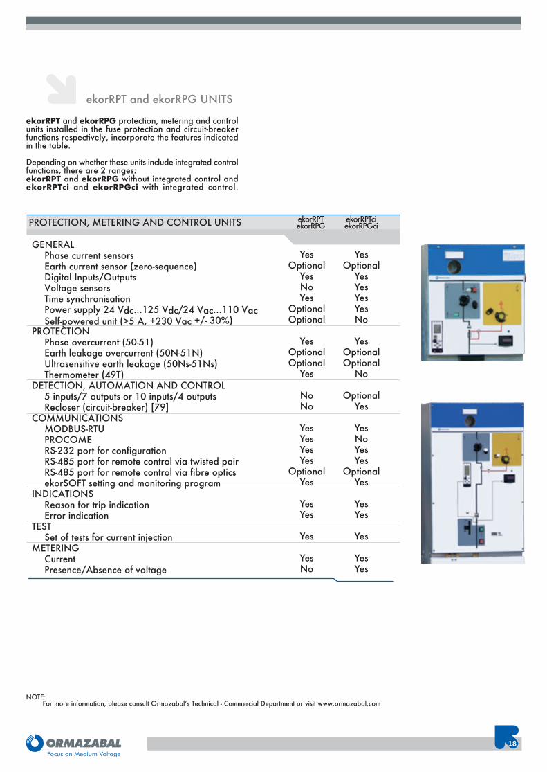
ekorRPT and ekorRPG UNITS
ekorRPT and ekorRPG protection, metering and controlunits installed in the fuse protection and circuit-breakerfunctions respectively, incorporate the features indicatedin the table.
Depending on whether these units include integrated controlfunctions, there are 2 ranges:ekorRPT and ekorRPG without integrated control andekorRPTci and ekorRPGci with integrated control.
GENERALPhase current sensorsEarth current sensor (zero-sequence)Digital Inputs/OutputsVoltage sensorsTime synchronisationPower supply 24 Vdc...125 Vdc/24 Vac...110 VacSelf-powered unit (>5 A, +230 Vac +/- 30%)
PROTECTIONPhase overcurrent (50-51)Earth leakage overcurrent (50N-51N)Ultrasensitive earth leakage (50Ns-51Ns)Thermometer (49T)
DETECTION, AUTOMATION AND CONTROL5 inputs/7 outputs or 10 inputs/4 outputsRecloser (circuit-breaker) [79]
COMMUNICATIONSMODBUS-RTUPROCOMERS-232 port for configurationRS-485 port for remote control via twisted pairRS-485 port for remote control via fibre opticsekorSOFT setting and monitoring program
INDICATIONSReason for trip indicationError indication
TESTSet of tests for current injection
METERINGCurrentPresence/Absence of voltage
YesOptional
YesNoYes
OptionalOptional
YesOptionalOptional
Yes
NoNo
YesYesYesYes
OptionalYes
YesYes
Yes
YesNo
PROTECTION, METERING AND CONTROL UNITS
NOTE:For more information, please consult Ormazabal’s Technical - Commercial Department or visit www.ormazabal.com
YesOptional
YesYesYesYesNo
YesOptionalOptional
No
OptionalYes
YesNoYesYes
OptionalYes
YesYes
Yes
YesYes
ekorRPTekorRPG
ekorRPTciekorRPGci
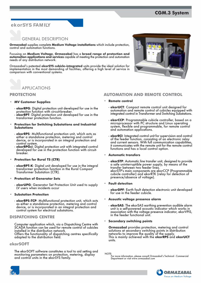
Ormazabal supplies complete Medium Voltage installations which include protection,control and automation functions.
Focusing on Medium Voltage, Ormazabal has a broad range of protection andautomation applications and services capable of meeting the protection and automationneeds of any distribution network.
Ormazabal’s patented ekorSYS cubicle-integrated units provide the ideal solution forimplementation in the most demanding of facilities, offering a high level of service incomparison with conventional systems.
GENERAL DESCRIPTION
ekorSYS FAMILY
19
CGM.3 System
APPLICATIONSPROTECTION
• MV Customer Supplies
- ekorRPG: Digital protection unit developed for use in theprotection function with circuit-breaker.
- ekorRPT: Digital protection unit developed for use in thetransformer protection function.
• Protection for Switching Substations and Industrial Substations
- ekorRPS: Multifunctional protection unit, which acts as either a standalone protection, metering and control device, or is incorporated in an integral protection and control system.
- ekorRPGci: Digital protection unit with integrated controldeveloped for use in the protection function with circuit-breaker.
• Protection for Rural TS (CTR)
- ekorRPT-K: Digital unit developed for use in the integraltransformer protection function in the Rural Compact Transformer Substation (CTR).
• Protection of Generator Sets
- ekorUPG: Generator Set Protection Unit used to supplyLV users when incidents occur
• Substation Protection
- ekorRPS-TCP: Multifunctional protection unit, which actsas either a standalone protection, metering and control device, or is incorporated in an integral protection and control system for electrical substations.
DISPATCHING CENTRE
Computer application which, via a Dispatching Centre withSCADA function can be used for remote control of cubiclesinstalled in the distribution network.Offers the functionality of dispatching centres specificallyadapted to the distribution field.
ekorSOFT
The ekorSOFT software constitutes a tool to aid setting andmonitoring parameters on protection, metering, display and control units in the ekorSYS family.
AUTOMATION AND REMOTE CONTROL• Remote control
- ekorUCT: Compact remote control unit designed for automation and remote control of cubicles equipped withintegrated control in Transformer and Switching Substations.
- ekorCCP: Programmable cubicle controller, based on amicroprocessor with PC structure and Linux operating system, flexible and programmable, for remote control and automation applications.
- ekorRCI: Integrated control unit for supervision and controlof the feeder function, consisting of an electronic relay and current sensors. With full communication capabilities,it communicates with the remote unit for the remote controlfunctions and has a local control option.
• Automatic transfers
- ekorSTP: Automatic line transfer unit, designed to providea safe uninterruptible power supply, by means of the transfer between two feeder lines.ekorSTP's main components are ekorCCP (Programmablecubicle controller) and ekorRTK (relay for detection of presence/absence of voltage).
• Fault detection
- ekorDPF: Earth fault detection electronic unit developedfor use in the feeder cubicle.
• Acoustic voltage presence alarm
- ekorSAS: The ekorSAS earthing prevention audible alarmunit is a self-powered acoustic indicator which works in association with the voltage presence indicator, ekorVPIS,in the feeder functional unit.
• Secondary switching points
Ormazabal provides protection, metering and control solutions at secondary switching points in distribution networks to improve the quality of the supply.This is mainly achieved with the ekorRPS and ekorUCT units.
NOTE:For more information, please consult Ormazabal’s Technical - CommercialDepartment or visit www.ormazabal.com
20
DRIVING MECHANISM
Depending on the actuator mechanism (three-positionswitch or circuit-breaker) there are different drivingmechanism models:
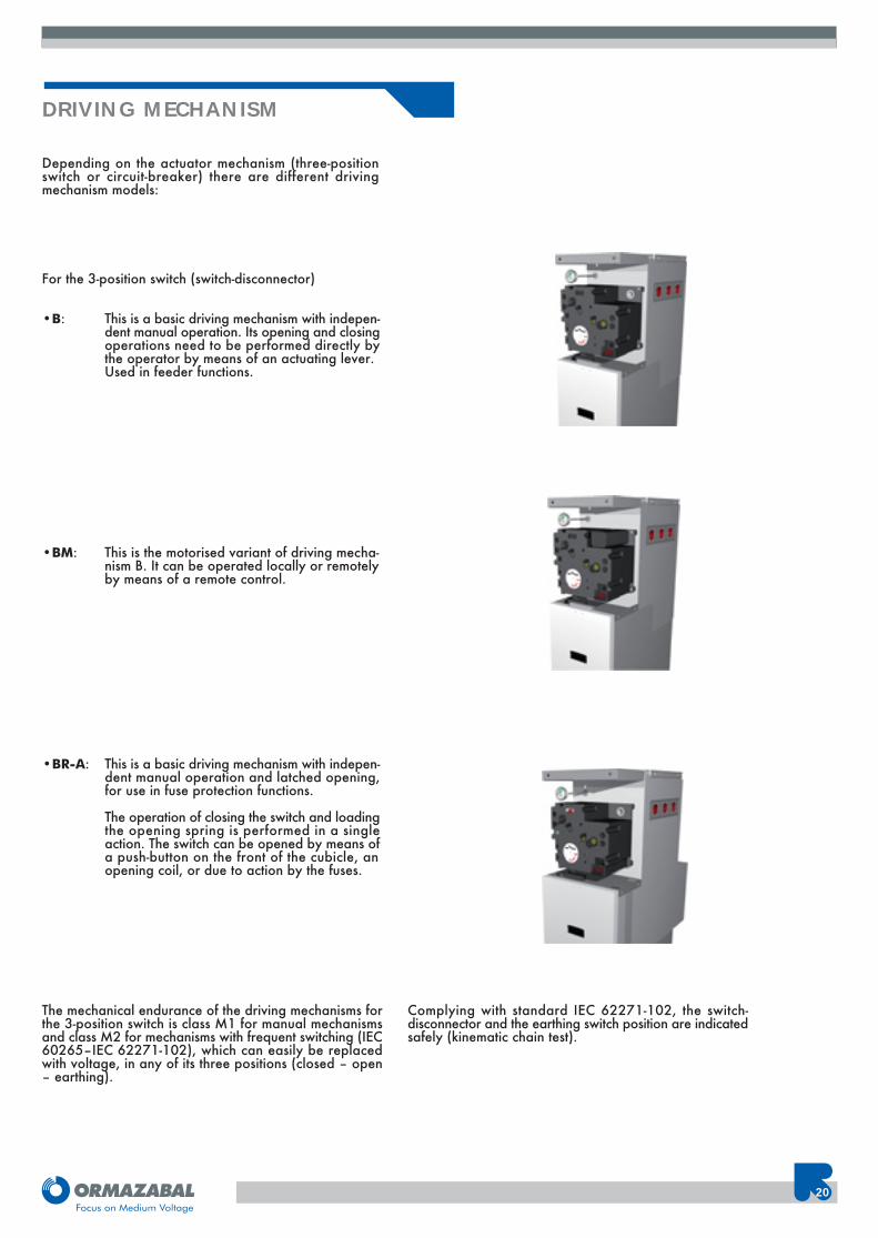
For the 3-position switch (switch-disconnector)
•B: This is a basic driving mechanism with indepen- dent manual operation. Its opening and closing
operations need to be performed directly bythe operator by means of an actuating lever. Used in feeder functions.
•BM: This is the motorised variant of driving mecha-nism B. It can be operated locally or remotelyby means of a remote control.
•BR-A: This is a basic driving mechanism with indepen- dent manual operation and latched opening,
for use in fuse protection functions.
The operation of closing the switch and loadingthe opening spring is performed in a singleaction. The switch can be opened by means ofa push-button on the front of the cubicle, anopening coil, or due to action by the fuses.
The mechanical endurance of the driving mechanisms forthe 3-position switch is class M1 for manual mechanismsand class M2 for mechanisms with frequent switching (IEC60265–IEC 62271-102), which can easily be replacedwith voltage, in any of its three positions (closed – open– earthing).
Complying with standard IEC 62271-102, the switch-disconnector and the earthing switch position are indicatedsafely (kinematic chain test).
21
CGM.3 System
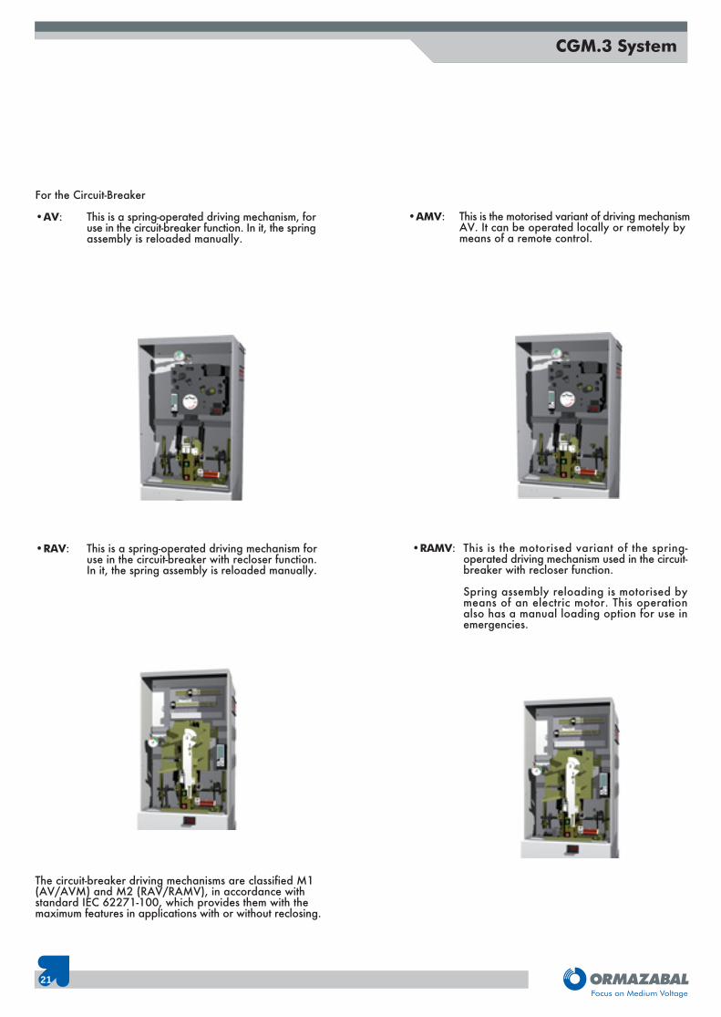
For the Circuit-Breaker
•AV: This is a spring-operated driving mechanism, foruse in the circuit-breaker function. In it, the springassembly is reloaded manually.
The circuit-breaker driving mechanisms are classified M1(AV/AVM) and M2 (RAV/RAMV), in accordance withstandard IEC 62271-100, which provides them with themaximum features in applications with or without reclosing.
•AMV: This is the motorised variant of driving mechanismAV. It can be operated locally or remotely by means of a remote control.
•RAV: This is a spring-operated driving mechanism foruse in the circuit-breaker with recloser function.In it, the spring assembly is reloaded manually.
•RAMV: This is the motorised variant of the spring-operated driving mechanism used in the circuit-breaker with recloser function.
Spring assembly reloading is motorised bymeans of an electric motor. This operationalso has a manual loading option for use inemergencies.
22
CABLE CONNECTIONS
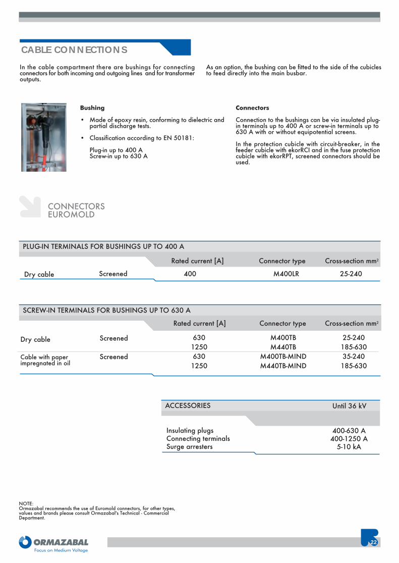
Bushing
• Made of epoxy resin, conforming to dielectric andpartial discharge tests.
• Classification according to EN 50181:
Plug-in up to 400 AScrew-in up to 630 A
Connectors
Connection to the bushings can be via insulated plug-in terminals up to 400 A or screw-in terminals up to630 A with or without equipotential screens.
In the protection cubicle with circuit-breaker, in thefeeder cubicle with ekorRCI and in the fuse protectioncubicle with ekorRPT, screened connectors should beused.
CONNECTORSEUROMOLD
Dry cable 400
PLUG-IN TERMINALS FOR BUSHINGS UP TO 400 A
25-240M400LR
Rated current [A] Connector type Cross-section mm2
Screened
Dry cable M400TBM440TB
M400TB-MINDM440TB-MIND
SCREW-IN TERMINALS FOR BUSHINGS UP TO 630 A
25-240185-63035-240185-630
Connector type Cross-section mm2
63012506301250
Rated current [A]
Screened
Screened
In the cable compartment there are bushings for connectingconnectors for both incoming and outgoing lines and for transformeroutputs.
As an option, the bushing can be fitted to the side of the cubiclesto feed directly into the main busbar.
Insulating plugsConnecting terminalsSurge arresters
ACCESSORIES
400-630 A400-1250 A
5-10 kA
Until 36 kV
NOTE:Ormazabal recommends the use of Euromold connectors, for other types,values and brands please consult Ormazabal's Technical - CommercialDepartment.
Cable with paperimpregnated in oil
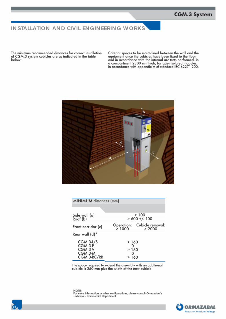
The minimum recommended distances for correct installationof CGM.3 system cubicles are as indicated in the tablebelow:
Criteria: spaces to be maintained between the wall and theequipment once the cubicles have been fixed to the floorand in accordance with the internal arc tests performed, ina compartment 2300 mm high, for gas-insulated modules,in accordance with appendix A of standard IEC 62271-200.
INSTALLATION AND CIVIL ENGINEERING WORKS
23
CGM.3 System
Side wall (a)Roof (b)
Front corridor (c)
Rear wall (d)*
CGM.3-L/SCGM.3-PCGM.3-VCGM.3-MCGM.3-RC/RB
> 100> 600 +/- 100
MINIMUM distances (mm)
Operation:> 1000
Cubicle removal:> 2000
> 1600
> 1600
> 160
b
c
d
a
NOTE:For more information or other configurations, please consult Ormazabal'sTechnical - Commercial Department.
The space required to extend the assembly with an additionalcubicle is 250 mm plus the width of the new cubicle.
24
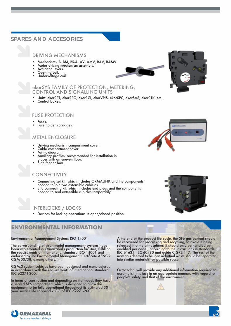
SPARES AND ACCESORIES
• Connecting set kit, which includes ORMALINK and the componentsneeded to join two extensible cubicles.
• End connecting kit, which includes end plugs and the components needed to seal extensible cubicles temporarily.
CONNECTIVITY
• Driving mechanism compartment cover.• Cable compartment cover.• Mimic diagram.• Auxiliary profiles: recommended for installation in
places with an uneven floor.• Side feeder box.
METAL ENCLOSURE
• Devices for locking operations in open/closed position.INTERLOCKS / LOCKS
ENVIRONMENTAL INFORMATION
Environmental Management System: ISO 14001
The corresponding environmental management systems havebeen implemented in Ormazabal's production facilities, fulfillingthe requirements of international standard ISO 14001 andendorsed by the Environmental Management Certificate AENORCGM-00/38, among others.
CGM.3 system cubicles have been designed and manufacturedin accordance with the requirements of international standardIEC 62271-200.
In terms of construction and depending on the model, they havea sealed SF6 compartment which is designed to allow theequipment to be fully operational throughout its estimated 30-year service life (appendix GG of IEC 62271-200).
A the end of the product life cycle, the SF6 gas content shouldbe recovered for processing and recycling, to avoid it beingreleased into the atmosphere. It should only be handled byqualified personnel, according to the instructions in standardsIEC 61634, IEC 60480 and guide CIGRE 117. The rest of thematerials deemed to be inert industrial waste should be separatedinto similar materials for possible reuse.
Ormazabal will provide any additional information required toaccomplish this task in an appropriate manner, with regard topeople's safety and that of the environment.
• Fuses.• Fuse holder carriages.
FUSE PROTECTION
ekorSYS FAMILY OF PROTECTION, METERING,CONTROL AND SIGNALLING UNITS• Units: ekorRPT, ekorRPG, ekorRCI, ekorVPIS, ekorSPC, ekorSAS, ekorRTK, etc.• Control boxes.
DRIVING MECHANISMS• Mechanisms: B, BM, BR-A, AV, AMV, RAV, RAMV.• Motor driving mechanism assembly.• Actuating levers.• Opening coil.• Undervoltage coil.
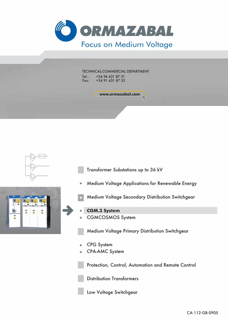
Transformer Substations up to 36 kV
Medium Voltage Applications for Renewable Energy
Medium Voltage Secondary Distribution Switchgear
CGM.3 SystemCGMCOSMOS System
Medium Voltage Primary Distribution Switchgear
CPG SystemCPA-AMC System
Protection, Control, Automation and Remote Control
Distribution Transformers
Low Voltage Switchgear
CA·112·GB·0905
TECHNICAL-COMMERCIAL DEPARTMENTTel.: +34 94 431 87 31Fax: +34 91 431 87 32
www.ormazabal.com