power technologies · iec 62271-100 high voltage alternating current circuit-breakers iec 62271-102...
TRANSCRIPT

ATS IEC Medium Voltage Transfers Switches
New Industrial Road 23, 08-04, Solstice Business Center, 536209 [email protected] - www.powertechnologies.com.sg
Power Technologies
THE HEART OF SMART CONTROL
2 MADE IN BELGIUM, ACTIVE WORLDWIDE
Power Technologies ATS IEC Medium
Voltage Power Transfer Switches
Power Continuity for:
• Chemical industry• Data centers• Healthcare facilities• Industrial complexes• Other mission critical facilities• Refineries• Retail business centers• Telecom exchanges• Waste water treatment
The availability, quality and reliability of electrical power can impact life, safety, productivity and financial success.
Power Technologies provides solutions to assure the continuity of power, from the design stage to installation, start-up and beyond: complete coverage for continuous power.
Power Technologies products can transform what could be a major catastrophe into complete assurance.
With a variety of configurations, options and transfer modes including open, delayed, and closed Medium Voltage Power Transfer Switches deliver per specifications and leverage industry leading switchgear per the IEC 62271-200 standard for metal-enclosed switchgear and controlgear.
3THE HEART OF SMART CONTROL
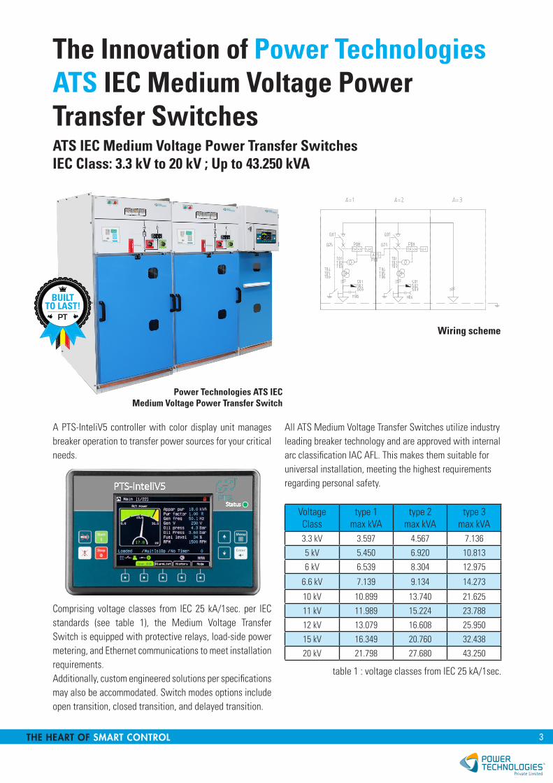
The Innovation of Power Technologies ATS IEC Medium Voltage Power Transfer SwitchesATS IEC Medium Voltage Power Transfer SwitchesIEC Class: 3.3 kV to 20 kV ; Up to 43.250 kVA
A PTS-InteliV5 controller with color display unit manages breaker operation to transfer power sources for your critical needs.
Comprising voltage classes from IEC 25 kA/1sec. per IEC standards (see table 1), the Medium Voltage Transfer Switch is equipped with protective relays, load-side power metering, and Ethernet communications to meet installation requirements.Additionally, custom engineered solutions per specifications may also be accommodated. Switch modes options include open transition, closed transition, and delayed transition.
All ATS Medium Voltage Transfer Switches utilize industry leading breaker technology and are approved with internal arc classification IAC AFL. This makes them suitable for universal installation, meeting the highest requirements regarding personal safety.
Voltage Class
type 1max kVA
type 2max kVA
type 3max kVA
3.3 kV 3.597 4.567 7.136
5 kV 5.450 6.920 10.813
6 kV 6.539 8.304 12.975
6.6 kV 7.139 9.134 14.273
10 kV 10.899 13.740 21.625
11 kV 11.989 15.224 23.788
12 kV 13.079 16.608 25.950
15 kV 16.349 20.760 32.438
20 kV 21.798 27.680 43.250
table 1 : voltage classes from IEC 25 kA/1sec.
Power Technologies ATS IECMedium Voltage Power Transfer Switch
Wiring schemePT
2.01
0
RP 600
8
5
2
7
4
1
WarningShutdownLine 1Line 2Line 3NeutralMagneticThermic
9
6
3
12345678
8,5 cm
9,4 cm
8 cm22 cm
17 cm
2,5
2.01
0
RP 600
8
5
2
7
4
1
WarningShutdownLine 1Line 2Line 3NeutralMagneticThermic
9
6
3
12345678
8,5 cm
9,4 cm
8 cm22 cm
17 cm
2,5
4 MADE IN BELGIUM, ACTIVE WORLDWIDE
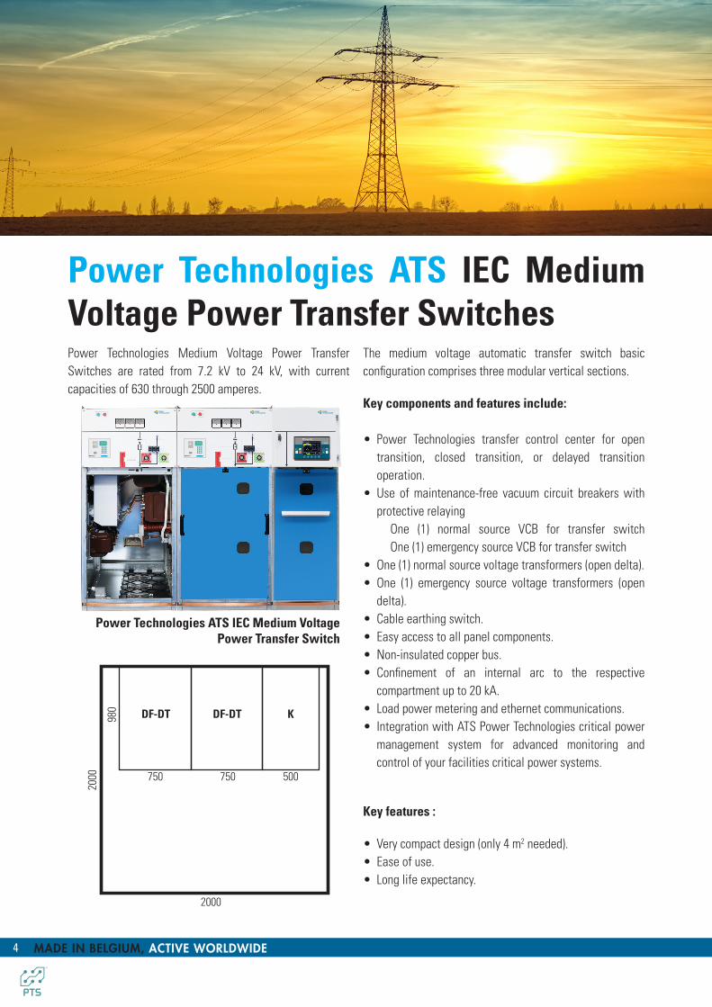
Power Technologies ATS IEC Medium Voltage Power Transfer SwitchesPower Technologies Medium Voltage Power Transfer Switches are rated from 7.2 kV to 24 kV, with current capacities of 630 through 2500 amperes.
Power Technologies ATS IEC Medium VoltagePower Transfer Switch
The medium voltage automatic transfer switch basic configuration comprises three modular vertical sections.
Key components and features include:
• Power Technologies transfer control center for open transition, closed transition, or delayed transition operation.
• Use of maintenance-free vacuum circuit breakers with protective relaying
One (1) normal source VCB for transfer switch One (1) emergency source VCB for transfer switch
• One (1) normal source voltage transformers (open delta).• One (1) emergency source voltage transformers (open
delta).• Cable earthing switch.• Easy access to all panel components.• Non-insulated copper bus.• Confinement of an internal arc to the respective
compartment up to 20 kA.• Load power metering and ethernet communications.• Integration with ATS Power Technologies critical power
management system for advanced monitoring and control of your facilities critical power systems.
Key features :
• Very compact design (only 4 m2 needed).• Ease of use.• Long life expectancy.
2000
2000
980
500750
DF-DT DF-DT K
750
2.01
0
RP 600
8
5
2
7
4
1
WarningShutdownLine 1Line 2Line 3NeutralMagneticThermic
9
6
3
12345678
8,5 cm
9,4 cm
8 cm22 cm
17 cm
2,5
2.01
0
RP 600
8
5
2
7
4
1
WarningShutdownLine 1Line 2Line 3NeutralMagneticThermic
9
6
3
12345678
8,5 cm
9,4 cm
8 cm22 cm
17 cm
2,5
5THE HEART OF SMART CONTROL
Transfer Switch Controller
The ATS Power Technologies transfer control center, providing refined and proven transfer control for low and medium voltage switches, leverages almost a century of power transfer innovation and application experience.
Circuit Breakers
ATS Medium Voltage Power Switch uses vacuum circuit breakers for superior reliability and maintainability.Each circuit breaker is listed according to according to IEC 62271-100 and is suitable for all indoor switching duties. Breakers are designed for maintenance-free operating under normal climatic conditions and for the maximum permissible number of 50.000 CO.
Normal Source and Emergency Source circuit breakers are interchangeable due to identical ratings and configuration, as standard. Magnetic driven include electric charging and manual charging handle. These circuit breakers have 50.000 operations maintenance-free.
Arc Safety
Internal arc classified switchgear according to IAC AFL; front, lateral accessibility for all short circuit currents and an arc duration of 1 s.
Instrument Transformers
Instrument transformers include Current Transformers (CT) and Voltage Transformers (VT, a.k.a. Potential Transformers - PT) to measure circuit voltage and current.
Controlgear Assembly
The controlgear assembly is air-insulated, type-tested, metal enclosed medium voltage switchgear for indoor installation complying with IEC 62271-200. The panel consists of 3 HV compartments: bus bar compartment, switching device compartment & cable compartment, and low voltage compartment.
The complete enclosure and the partitions between the individual compartments and covers are metallic and earthed. These features guarantee the highest possible service continuity category.
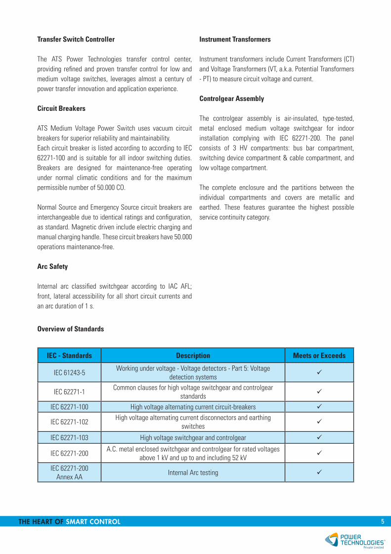
Overview of Standards
IEC - Standards Description Meets or Exceeds
IEC 61243-5 Working under voltage - Voltage detectors - Part 5: Voltage detection systems
IEC 62271-1 Common clauses for high voltage switchgear and controlgear standards
IEC 62271-100 High voltage alternating current circuit-breakers
IEC 62271-102 High voltage alternating current disconnectors and earthing switches
IEC 62271-103 High voltage switchgear and controlgear
IEC 62271-200 A.C. metal enclosed switchgear and controlgear for rated voltages above 1 kV and up to and including 52 kV
IEC 62271-200Annex AA Internal Arc testing

6 MADE IN BELGIUM, ACTIVE WORLDWIDE
Protection cubicle with vacuum circuit breaker (magnetic driven) with integrated protection relay.
DF-DT
Standard Equipment :• Triple-phase load break switch RV-44 - class E3
according to IEC 62271-103, SF6 insulation• Vacuum circuit breaker with magnetic drive • Interlocked earthing switch with a rated making
capacity up to 63 kA downstream of the circuit breaker• Cable support structure• Door interlock• Sockets for capacitive voltage detectors• Voltage presence indicators• LV compartment• Floor panels• Current transformer• Voltage transformer• Auxiliary contacts on the load break switch• Auxiliary contacts on the earthing switch• Voltage indication
Cubicle options :• Earthing connection upstream from the circuit breaker• • Cubicle base: 200, 300, 400 mm height (other
dimensions on demand)• Only with motor on LBS:
- Button press control on the load break switch- Remote control of the load break switch
Specifications & dimensions :Rated Voltage kV 12 17,5 24
Rated current A 800/1250 800/1250 630/1250
Short-term current kA 16/20/25 16/20/25 16
Time of the short duration of current
s 1/2/3 1/2/3 1/2/3
Width mm 750 750 750
Depth mm 940 940 940
Height mm 1700 1700 1700
Height between ground and socket
mm 450 450 450
Weight kg 360 360 360
APPLICATION
Protection of feeders with circuit breaker, voltage and current transformer and MV protection (max 1250 A).
On the circuit breaker :• Under-voltage release (electronic)• Block auxiliary contacts• Operation counter• Reclosing function (standard)• Remote control• Interlock
750
1700
750
1700
360
940
Ø10
100
6077
5
570
750
1050

7THE HEART OF SMART CONTROL
1700
500 500
1700
900
940
Ø79
100400
Ø10
500210
900
150
775
990
365
570
6021
0
55
Options :• Cubicle base: 200 mm, 300 mm of 400 mm height
(other dimensions on demand)• Floor panels
Specifications & dimensions :Rated Voltage kV 12 17,5 24
Rated current A 800/1250 800/1250 800/1250
Short-term current kA 25 25 25
Time of the short duration of current
s 1 1 1
Width mm 500 500 500
Depth mm 1050 1050 1050
Height mm 1700 1700 1700
Weight kg 55 55 55
Cubicles of the DF-2 type equipped to bring in a supply cable. However, a DF-K cubicle can also contain a busbar and can be used as rising cubicle of the rail set.
APPLICATION
PT
Download our User Manual
Cable Cubicle and/or rail shaft.DF-K
8 MADE IN BELGIUM, ACTIVE WORLDWIDE
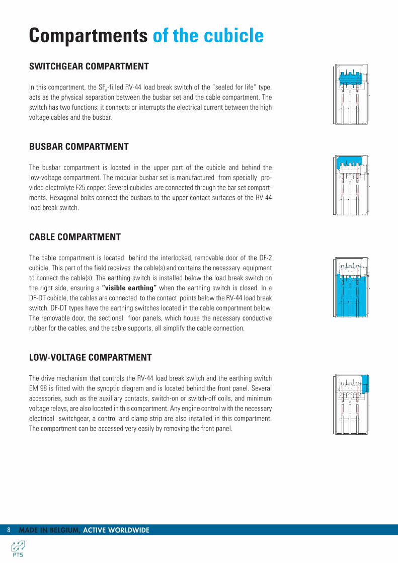
SWITCHGEAR COMPARTMENT
In this compartment, the SF6-filled RV-44 load break switch of the “sealed for life” type, acts as the physical separation between the busbar set and the cable compartment. The switch has two functions: it connects or interrupts the electrical current between the high voltage cables and the busbar.
BUSBAR COMPARTMENT
The busbar compartment is located in the upper part of the cubicle and behind the low-voltage compartment. The modular busbar set is manufactured from specially pro-vided electrolyte F25 copper. Several cubicles are connected through the bar set compart-ments. Hexagonal bolts connect the busbars to the upper contact surfaces of the RV-44 load break switch.
CABLE COMPARTMENT
The cable compartment is located behind the interlocked, removable door of the DF-2 cubicle. This part of the field receives the cable(s) and contains the necessary equipment to connect the cable(s). The earthing switch is installed below the load break switch on the right side, ensuring a “visible earthing” when the earthing switch is closed. In a DF-DT cubicle, the cables are connected to the contact points below the RV-44 load break switch. DF-DT types have the earthing switches located in the cable compartment below. The removable door, the sectional floor panels, which house the necessary conductive rubber for the cables, and the cable supports, all simplify the cable connection.
LOW-VOLTAGE COMPARTMENT
The drive mechanism that controls the RV-44 load break switch and the earthing switch EM 98 is fitted with the synoptic diagram and is located behind the front panel. Several accessories, such as the auxiliary contacts, switch-on or switch-off coils, and minimum voltage relays, are also located in this compartment. Any engine control with the necessary electrical switchgear, a control and clamp strip are also installed in this compartment. The compartment can be accessed very easily by removing the front panel.
Compartments of the cubicle

9THE HEART OF SMART CONTROL
Internal Arc Resistance
The various tests were always in accordance with IAC (AFL) for 16kA/20kA/1s. according to IEC 62271-200.
before test (IAC 20 kA/1 sec.
after test (IAC 20 kA/1 sec.
A short-circuit or another malfunction can create an internal arc. An internal arc in a classic MV cubicle, could severely damage the installation and possibly injure the operator and electrocute him or her.
The DF-2 is designed to resist internal arcs, protecting both the operator and the installation. Through a strategic pressure release system, the internal arc is restricted to the compartment where it originated and it does not propagate towards the operator or to other compartments.
The anti-arc kit of DF-2 cubicles is specifically designed to minimize the consequences of an internal arc. By default all provided cubicles are fitted on the rear side with overpressure valves pointing downward, in order to release the hot gasses upward.
The four valves are equally spaced among the total height of the cubicles: The upper valve is for the busbar and the three other valves protect both the cable compartment and the equipment compartment. The cubicle roof is fitted lengthwise over a depth of 100 mm.
Upon delivery, two reinforced side plates will be supplied in order to close the cabin completely, both to the left and right sides against the wall. At the rear of the cubicle, a buffer volume will be provided, in order to release the hot gasses upwards.
For applications in accessible concrete outdoor cabins, the anti-arc kit allows gasses to be diverted to the basement area. There is an exhaust opening in the floor panel along the side of the wall specifically for this purpose.
DF-2 cubicles were tested at Kema IAC (AFL) for 16kA/20kA/1s. at a rated voltage of 17.5 kV/24 kV according to IEC 62271-200, appendix A and met the 5 criteria.
Consequently, all Power Technologies cubicles are internal arc resistant.

10 MADE IN BELGIUM, ACTIVE WORLDWIDE
Visible earthing switchThe earthing switch is installed below the load break switch on the right side, ensuring a “visible earthing” when the earthing switch is closed.
This is the online safe manner in which the operator can visually check the position of the switch through the windows in the door of each cubicle. The switching takes place in the air. The two controls, the load break switch and the earthing switch, have been accommodated in one control mechanism. As the requirments of the IEC standard have been met, these two controls are also mutually interlocked mechanically whereby any incorrect switch operation is excluded.
It is important to mention that the Earthing Switch mechanism is also completely independent of the operator. An interesting feature is that the earting point can be very easily assembled and disassembled, and is virtually maintenance free. High safety is due to the operator always being able to see the state of the earting contacts through the windows.
Remote Switching & Monitoring Device(optionally)High energy efficiency, lower operational costs, increased lifespan of the equipment, eliminating equipment downtime, ensuring uptime. As a plant, production, maintenance, installation manager or technician you feel increasing the pressure day in day out, to let the equipment and installations perform more efficient, at a lower cost for a longer lifespan and still ensuring a higher productivity rate.
Features :
Online tool with real-time information of the medium voltage switchgear.
Monitoring :• Position indication.• Measuring: - temperature. - humidity. - ozone.• Load monitoring using current and voltage transformers.• Notifications (alarm or warning).
Switching :• Remote control of motorised switchgear.
Operation counter: 179
Analog values
PD effects 18.38 ppmAmbient temperature 12.86 °CHumidity 33.4 %
WELCOME, user-102. CHANGE PASSWORD LOG OUT
Web-driven interface.
11THE HEART OF SMART CONTROL
Every action can be interrupted at any time by pressing the cancellation key. When the programming is activated, the “warning” LED is on and the characters “Ep” appear in the bottom left corner of the display.
It is possible in the “programming function” to modify the different parameters. Using the arrow keys, select the required menu and confirm by using the “confirm” key. The value will now start to flash and allow the registration of a new value.
If the parameter is not a value, then the arrow keys allow you to select the language, the ratio and the curve. When all the values are programmed and confirmed, they will be placed in the system’s memory.
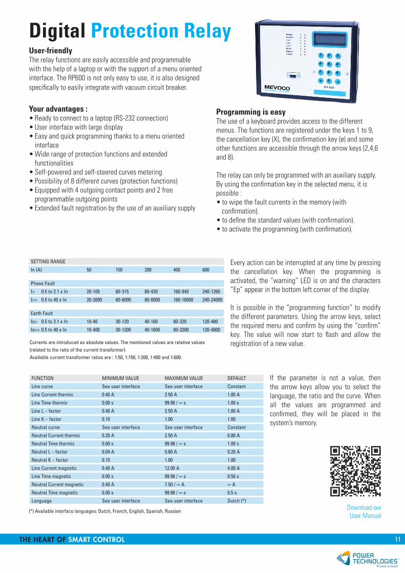
User-friendlyThe relay functions are easily accessible and programmable with the help of a laptop or with the support of a menu oriented interface. The RP600 is not only easy to use, it is also designed specifically to easily integrate with vacuum circuit breaker.
Your advantages :• Ready to connect to a laptop (RS-232 connection)• User interface with large display• Easy and quick programming thanks to a menu oriented
interface• Wide range of protection functions and extended
functionalities• Self-powered and self-steered curves metering• Possibility of 8 different curves (protection functions)• Equipped with 4 outgoing contact points and 2 free
programmable outgoing points• Extended fault registration by the use of an auxiliary supply
SETTING RANGE
In (A) 50 150 200 400 600
Phase Fault
I> 0.5 to 2.1 x In 20-105 60-315 80-420 160-840 240-1260
I>> 0.5 to 40 x In 20-2000 60-6000 80-8000 160-16000 240-24000
Earth Fault
Io> 0.5 to 2.1 x In 10-40 30-120 40-160 80-320 120-480
Io>> 0.5 to 40 x In 10-400 30-1200 40-1600 80-3200 120-4800
Currents are introduced as absolute values. The mentioned values are relative values (related to the ratio of the current transformer). Available current transformer ratios are : 1:50, 1:150, 1:200, 1:400 and 1:600.
Programming is easyThe use of a keyboard provides access to the different menus. The functions are registered under the keys 1 to 9, the cancellation key (X), the confirmation key (ø) and some other functions are accessible through the arrow keys (2,4,6 and 8).
The relay can only be programmed with an auxiliary supply. By using the confirmation key in the selected menu, it is possible :• to wipe the fault currents in the memory (with
confirmation).• to define the standard values (with confirmation).• to activate the programming (with confirmation).
FUNCTION MINIMUM VALUE MAXIMUM VALUE DEFAULT
Line curve See user interface See user interface Constant
Line Current thermic 0.40 A 2.50 A 1.00 A
LineTimethermic 0.00s 99.98/∞s 1.00s
Line L – factor 0.40 A 2.50 A 1.00 A
Line K – factor 0.10 1.00 1.00
Neutral curve See user interface See user interface Constant
Neutral Current thermic 0.20 A 2.50 A 0.80 A
NeutralTimethermic 0.00s 99.98/∞s 1.00s
Neutral L – factor 0.04 A 0.80 A 0.20 A
Neutral K – factor 0.10 1.00 1.00
Line Current magnetic 0.40 A 12.00 A 4.00 A
LineTimemagnetic 0.00s 99.98/∞s 0.50s
NeutralCurrentmagnetic 0.40A 7.50/∞A ∞A
NeutralTimemagnetic 0.00s 99.98/∞s 0.5s
Language See user interface See user interface Dutch (*)
(*) Available interface languages: Dutch, French, English, Spanish, Russian
Digital Protection Relay
Download ourUser Manual

12 MADE IN BELGIUM, ACTIVE WORLDWIDE
Transitions options and control modesConfigurable for Open- or Closed-Transition Transfer
Switches may be configured for open or closed-transition transfer.For either configuration, if the primary source is lost, the control initiates an open-transition transfer to the emergency source by tripping the breaker from the primary source and closing the breaker to the emergency source.For open-transition transfer, once power has been restored, retransfer to normal is accomplished by reversing this process - first tripping the breaker from the emergency source and then closing the breaker to the primary source. The two sources cannot operate in parallel, it’s open-transition transfer system.For closed-transition retransfer to the normal source, the PTS-InteliV5 control’s power monitoring functions ensure that both sources are within an acceptable window of synchronism before effecting a closed-transition retransfer to the normal source by first closing the normal sourcebreaker and then opening the emergency source breaker. It’s possible for load to betransferred from Source 1 to Source 2 without interruption of power to the load when both sources are available. The source paralleling during load transfer is less than 100 milliseconds.
Adjustable Center-Off Time Delay
In open-transition transfers between two live sources where large inductive loads are involved, induced voltage transients can result in a lack of synchronism between the sources, causing a bump upon transfer. A time delay between the opening of the primary source breaker and the closing of the secondary source breaker allows these voltage transients to decay. This center-off delay is factory preset at 3 seconds, but can be adjusted via the PTS-InteliV5 control.Center-off positioning is ideal for loadshed control schemes.
Manual Bypass/Isolation Capability
PTS Series Medium-Voltage Circuit-Breaker Bypass/Isolation Switches provide all the functions of an automatic transfer switch plus the ability to bypass power from a live source to load in the event the transfer switch becomes disabled. In addition, they are designed to allow isolation and de-energization of the automatic transfer breaker for maintenance, testing, or repair.Operator can easily choose between load-break bypass or no-load-break bypass by means of a selector switch on the front of the control cubicle.Compartmentalized design ensures personnel safety and simplifies installation.Sequencing of circuit breakers allows for open or closed-transition transfer.PTS-InteliV5 programmable microprocessor based control system.
SOURCE 1 BUS
ATS BYPASS SECTION (OPTIONAL)
SOURCE 2 BUS
SOURCE 1
SOURCE 2
SOURCE 1BREAKER
MAIN BUS
LOAD
SOURCE 1 BYPASS BREAKER
SOURCE 2BREAKER
SOURCE 2BYPASS BREAKER
PTS Medium-Voltage ATSBypass/Isolation Switches
13THE HEART OF SMART CONTROL
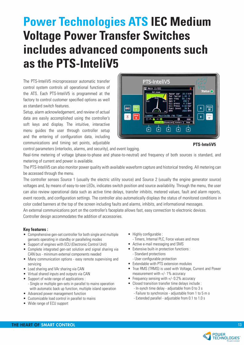
Power Technologies ATS IEC Medium Voltage Power Transfer Switches includes advanced components such as the PTS-InteliV5The PTS-InteliV5 microprocessor automatic transfer control system controls all operational functions of the ATS. Each PTS-InteliV5 is programmed at the factory to control customer specified options as well as standard switch features.Setup, alarm acknowledgement, and review of actual data are easily accomplished using the controller’s soft keys and display. The intuitive, interactive menu guides the user through controller setup and the entering of configuration data, including communications and timing set points, adjustable PTS-InteliV5control parameters (interlocks, alarms, and security), and event logging.Real-time metering of voltage (phase-to-phase and phase-to-neutral) and frequency of both sources is standard, and metering of current and power is available.The PTS-InteliV5 can also monitor power quality with available waveform capture and historical trending. All metering can be accessed through the menu.The controller senses Source 1 (usually the electric utility source) and Source 2 (usually the engine generator source) voltages and, by means of easy-to-see LEDs, indicates switch position and source availability. Through the menu, the user can also review operational data such as active time delays, transfer inhibits, metered values, fault and alarm reports, event records, and configuration settings. The controller also automatically displays the status of monitored conditions in color coded banners at the top of the screen including faults and alarms, inhibits, and informational messages.An external communications port on the controller’s faceplate allows fast, easy connection to electronic devices.Controller design accommodates the addition of accessories.
Key features :• Comprehensive gen-set controller for both single and multiple
gensets operating in standby or paralleling modes• Support of engines with ECU (Electronic Control Unit)• Complete integrated gen-set solution and signal sharing via
CAN bus - minimum external components needed• Many communication options - easy remote supervising and
servicing• Load sharing and VAr sharing via CAN• Virtual shared inputs and outputs via CAN• Support of wide range of applications :
- Single or multiple gen-sets in parallel to mains operation with automatic back up function, multiple island operation
• Advanced power management function• Customizable load control in parallel to mains• Wide range of ECU support
• Highly configurable :- Timers, Internal PLC, Force values and more
• Active e-mail messaging and SMS• Extensive built-in protection functions :
- Standard protections- User configurable protection
• Extendable with PTS extension modules• True RMS (TRMS) is used with Voltage, Current and Power
measurement with +/- 1% accuracy• Frequency sensing with +/- 0.2% accuracy• Closed transition transfer time delays include :
- In-synch time delay - adjustable from 0 to 3 s- Failure to synchronize - adjustable from 1 to 5 m o- Extended parallel - adjustable from 0.1 to 1.0 s
14 MADE IN BELGIUM, ACTIVE WORLDWIDE
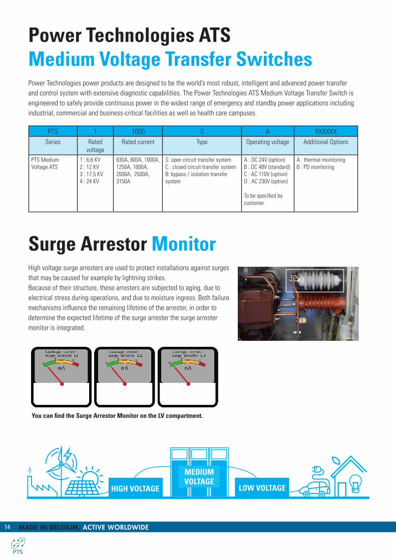
Power Technologies ATS Medium Voltage Transfer SwitchesPower Technologies power products are designed to be the world’s most robust, intelligent and advanced power transfer and control system with extensive diagnostic capabilities. The Power Technologies ATS Medium Voltage Transfer Switch is engineered to safely provide continuous power in the widest range of emergency and standby power applications including industrial, commercial and business-critical facilities as well as health care campuses.
PTS 1 1000 S A XXXXXXSeries Rated
voltageRated current Type Operating voltage Additional Options
PTS Medium Voltage ATS
1 : 6,6 KV 2 : 12 KV3 : 17,5 KV4 : 24 KV
630A, 800A, 1000A, 1250A, 1600A, 2000A, 2500A, 3150A
S: open circuit transfer systemC : closed circuit transfer systemB: bypass / isolation transfer system
A : DC 24V (option)B : DC 48V (standard)C : AC 110V (option)D : AC 230V (option)
To be specified by customer.
A : thermal monitoringB : PD monitoring
HIGH VOLTAGE LOW VOLTAGE
MEDIUM VOLTAGE
Surge Arrestor Monitor High voltage surge arresters are used to protect installations against surges that may be caused for example by lightning strikes.Because of their structure, these arresters are subjected to aging, due to electrical stress during operations, and due to moisture ingress. Both failure mechanisms influence the remaining lifetime of the arrester, in order to determine the expected lifetime of the surge arrester the surge arrester monitor is integrated.
You can find the Surge Arrestor Monitor on the LV compartment.

15THE HEART OF SMART CONTROL
THE HEARTOF SMART CONTROL
Technology
Power Technologies Private Limited (PT) specialises in end-to-end LV and MV switching control gears, predictive non-contact thermal monitoring solutions bring industrial IoT, Big Data & A.I to organizations in need of real-time business insights. In today’s digital age, power is more than just a convenience but it’s an essential component in securing business continuity.
Regardless of the industry, our approach is to measure something, learn something from the data, and then to assist our customers in taking action based on the high-value business insights that we generate.
Service
By equipping with over 20 years of experiences in the power protection industry, PT is positioned with its state-of-art solutions in answering today’s most critical and demanding power protection requirement and challenges.
From the most innovative products to turnkey design and engineering services, mission critical industries & clients can count on us and combining with our personal service, support and forward thinking, we are responding to your future needs immediately. Our portfolio and solution are designed with the key intent to accomplish specific customer requirements whether it is to complement new or pre-existing solutions and or providing a complete comprehensive solution.
In ensuring a complete competitive advantage to our clients, we provide an end to end solutions by delivering, installing, commissioning and pro-actively maintain and manage the power protection systems as a critical asset through its designed life-cycle. At PT, we deliver support services 24 hours a day, 7 days a week, 365 a year, whenever and wherever you require our support. Our services include : • Critical systems start-up.
• Corrective & preventive maintenance.• Operator training support.• Monitoring solutions.• Original factory spare parts and upgrades.
PT

THE HEART OF SMART CONTROL
POWER TECHNOLOGIESNo.23 New Industrial RoadSolstice Business Center#08-04, Singapore 536209
+65 90 30 31 [email protected]