the skf microlog series catalogue - sutaiyo
TRANSCRIPT
The SKF Microlog series catalogueThe industry’s premier range of portable, handheld data collectors and analyzers
Unmatched versatility, reliability and functionality have made the
SKF Microlog Analyzer series of data collectors the premier choice
for portable, handheld condition monitoring units.
Designed to help users establish or upgrade an existing condition
monitoring program, SKF Microlog Analyzers handle the tasks
required to perform predictive maintenance on rotating machinery
in countless industries.
Data capture from a range of sourcesSKF Microlog Analyzers automatically collect both dynamic (vibra-
tion) and static (process) measurements from almost any source,
including handheld and magnetically mounted accelerometers, per-
manently mounted vibration sensors or on-line monitoring systems.
Temperature measurements can be collected with a non-contact
infrared sensor or with a contact probe.
SKF Microlog seriesData collectors and analyzers
State-of-the-art operating technologyWith robust, high-speed data processors and optimum data storage
capacity, SKF Microlog Analyzers are equipped to operate within
today’s most advanced computerized maintenance management
systems. Units can be purchased with a range of individual modules
and accessories for specific types of analysis required to meet their
plant’s monitoring needs.
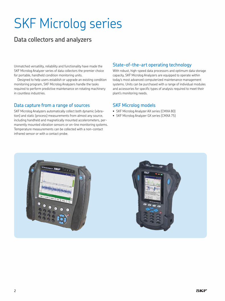
SKF Microlog models• SKF Microlog Analyzer AX series (CMXA 80)
• SKF Microlog Analyzer GX series (CMXA 75)
2
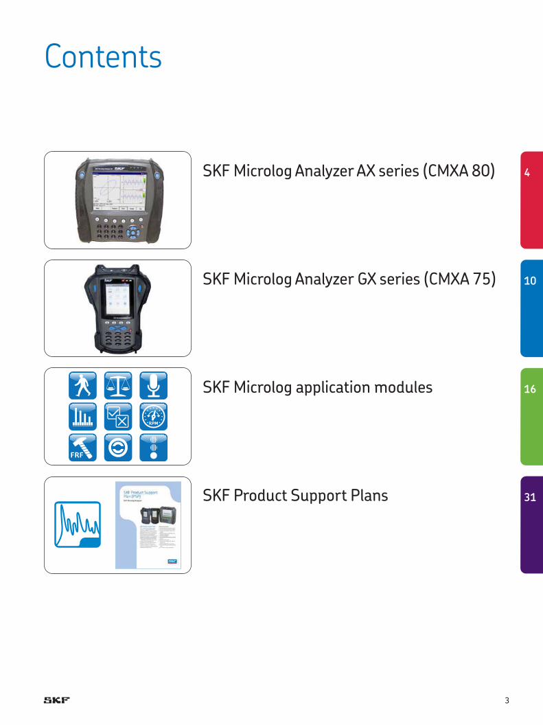
SKF Microlog Analyzer AX series (CMXA 80)
SKF Microlog Analyzer GX series (CMXA 75)
SKF Microlog application modules
SKF Product Support Plans
Contents
3
31
16
10
4
SKF Microlog Analyzer AX seriesCMXA 80
Advanced data collector / FFT analyzer
The SKF Microlog Analyzer AX is the most advanced large screen
route based analyzer offered by SKF today. The SKF Microlog AX’s
features allow you to capture a wide range of vibration data quickly.
The analyzer provides the flexibility to support applications that
are most important to your company’s specific predictive mainte-
nance program. Developed for use in a wide range of industries, the
SKF Microlog AX series is approved for use in hazardous environ-
ments requiring ATEX, IECEx and Class I Division 2 certifications.
Key features• Simultaneous triaxial or four channel measurements for fast data
collection
• Marvell 806 MHz PXA320 processor means faster real time rate
and display updates
• Rugged, dust / waterproof IP 65 design for reliability in industrial
environments
• Rechargeable lithium battery supports eight hours of continuous
data collection
• Large 6.4 in. VGA color display for easy viewing and analysis in
any light
SKF Microlog Analyzer AX seriesThe SKF Microlog AX facilitates easier, more powerful condition
monitoring by analyzing vibration signals and process variables
using four channel non-route measurements and one or two plane
static or dynamic couple balancing applications over a range of
0,16 Hz to 80 kHz (10 to 4 800 000 CPM). Bearing assessments are
carried out using the industry proven SKF Acceleration Enveloping
(gE) technology. The SKF Microlog AX utilizes the latest advances in
analog and digital electronics, including digital signal processing
(DSP) and high resolution sigma-delta A/D converters, to provide
both speed and accuracy in the data collection process.
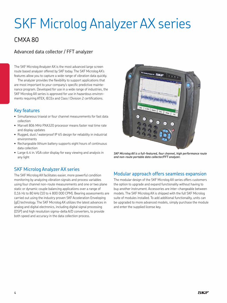
SKF Microlog AX is a full-featured, four channel, high performance route and non-route portable data collector/FFT analyzer.
Modular approach offers seamless expansionThe modular design of the SKF Microlog AX series offers customers
the option to upgrade and expand functionality without having to
buy another instrument. Accessories are inter-changeable between
models. The SKF Microlog AX is shipped with the full SKF Microlog
suite of modules installed. To add additional functionality, units can
be upgraded to more advanced models, simply purchase the module
and enter the supplied license key.
4
Key features• One software program to manage asset condition data from port-
able and on-line devices
• Easy for novice or experienced users to learn and use
• Interconnectivity with multiple enterprise-wide software pro-
grams and systems
• Scalable and flexible to meet your unique needs
– Start with one of three base models and expand functionality
according to your needs
– Easy personalization for individual users
– Application add-ons extend core functionality without migration
to other base models
– User access control to support functional roles and department
needs
– User programmable functions compute your company’s KPIs
(Key Performance Indicators)
• Supports Oracle and Microsoft SQL Server database managers
• Compliance reporting and scheduling direct tasks and workforce
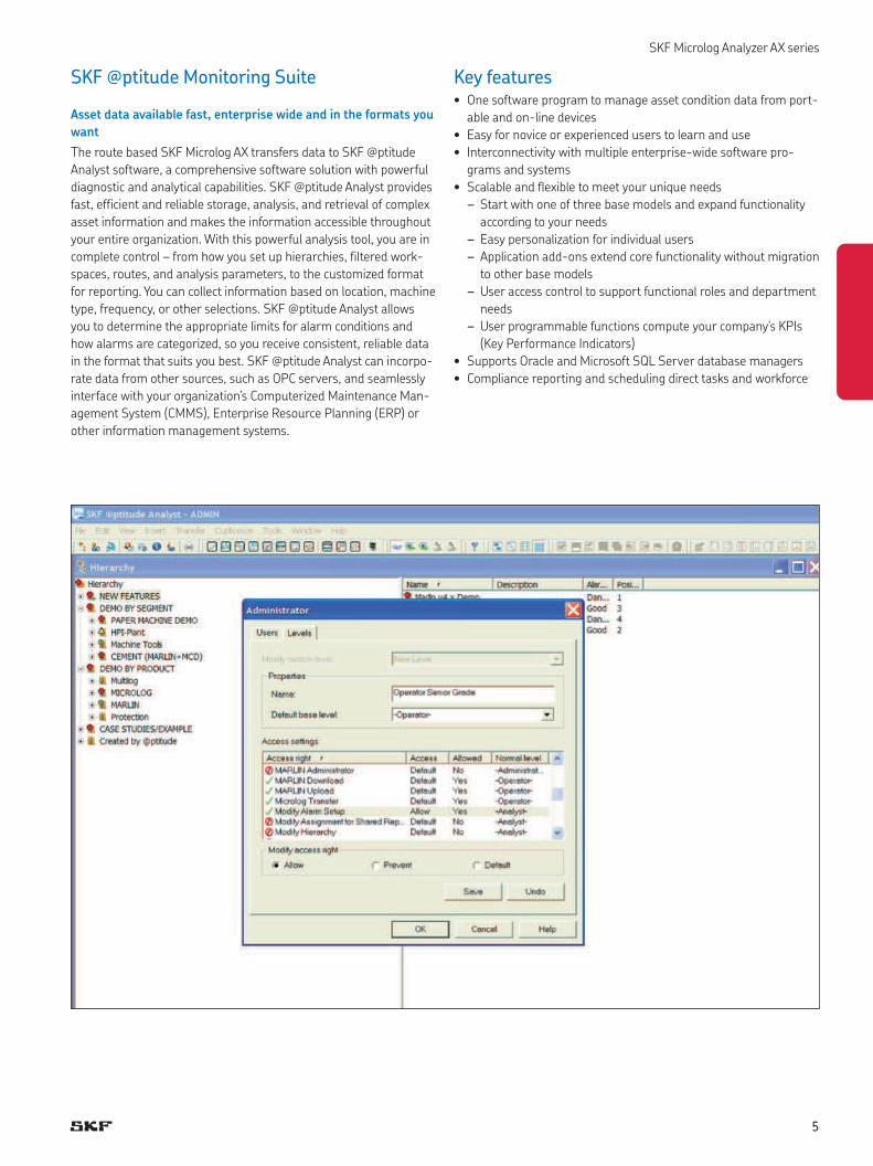
SKF @ptitude Monitoring Suite
Asset data available fast, enterprise wide and in the formats you
want
The route based SKF Microlog AX transfers data to SKF @ptitude
Analyst software, a comprehensive software solution with powerful
diagnostic and analytical capabilities. SKF @ptitude Analyst provides
fast, efficient and reliable storage, analysis, and retrieval of complex
asset information and makes the information accessible throughout
your entire organization. With this powerful analysis tool, you are in
complete control – from how you set up hierarchies, filtered work-
spaces, routes, and analysis parameters, to the customized format
for reporting. You can collect information based on location, machine
type, frequency, or other selections. SKF @ptitude Analyst allows
you to determine the appropriate limits for alarm conditions and
how alarms are categorized, so you receive consistent, reliable data
in the format that suits you best. SKF @ptitude Analyst can incorpo-
rate data from other sources, such as OPC servers, and seamlessly
interface with your organization’s Computerized Maintenance Man-
agement System (CMMS), Enterprise Resource Planning (ERP) or
other information management systems.
SKF Microlog Analyzer AX series
5
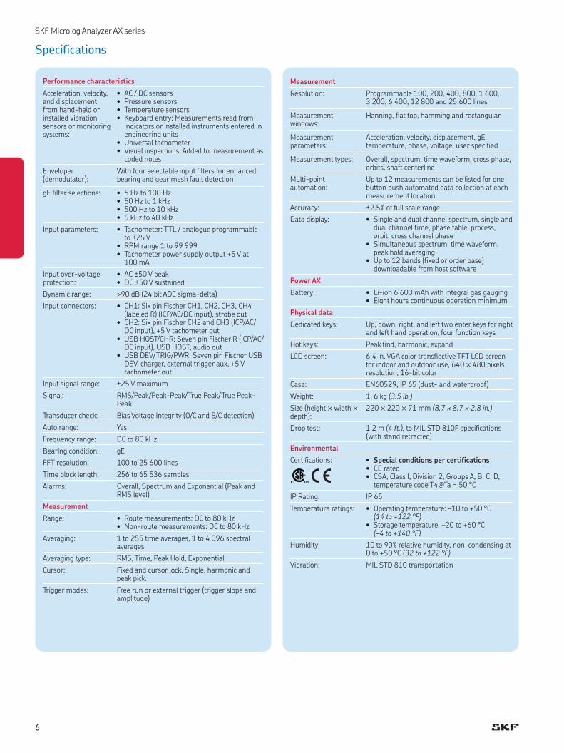
Measurement
Resolution: Programmable 100, 200, 400, 800, 1 600, 3 200, 6 400, 12 800 and 25 600 lines
Measurement windows:
Hanning, flat top, hamming and rectangular
Measurement parameters:
Acceleration, velocity, displacement, gE, temperature, phase, voltage, user specified
Measurement types: Overall, spectrum, time waveform, cross phase, orbits, shaft centerline
Multi-point automation:
Up to 12 meas urements can be listed for one button push automated data collection at each measurement location
Accuracy: ±2.5% of full scale range
Data display: • Single and dual channel spectrum, single and dual channel time, phase table, process, orbit, cross channel phase
• Simultaneous spectrum, time waveform, peak hold averaging
• Up to 12 bands (fixed or order base) downloadable from host software
Power AX
Battery: • Li-ion 6 600 mAh with integral gas gauging• Eight hours continuous operation minimum
Physical data
Dedicated keys: Up, down, right, and left two enter keys for right and left hand operation, four function keys
Hot keys: Peak find, harmonic, expand
LCD screen: 6.4 in. VGA color transflective TFT LCD screen for indoor and outdoor use, 640 ™ 480 pix els resolution, 16-bit color
Case: EN60529, IP 65 (dust- and waterproof)
Weight: 1, 6 kg (3.5 lb.)
Size (height ™ width ™ depth):
220 ™ 220 ™ 71 mm (8.7 ¥ 8.7 ¥ 2.8 in.)
Drop test: 1.2 m (4 ft.), to MIL STD 810F specifications (with stand retracted)
Environmental
Certifications: • Special conditions per certifications• CE rated• CSA, Class I, Division 2, Groups A, B, C, D,
temperature code T4@Ta = 50 °C
IP Rating: IP 65
Temperature ratings: • Operating temperature: –10 to +50 °C (14 to +122 °F)
• Storage temperature: –20 to +60 °C (–4 to +140 °F)
Humidity: 10 to 90% relative humidity, non-condensing at 0 to +50 °C (32 to +122 °F)
Vibration: MIL STD 810 transportation
Specifications
Performance characteristics
Acceleration, velocity, and displacement from hand-held or installed vibration sensors or monitoring systems:
• AC / DC sensors• Pressure sensors• Temperature sensors• Keyboard entry: Measurements read from
indicators or installed instruments entered in engineering units
• Universal tachometer• Visual inspections: Added to measurement as
coded notes
Enveloper (demodulator):
With four selectable input filters for enhanced bearing and gear mesh fault detection
gE filter selections: • 5 Hz to 100 Hz• 50 Hz to 1 kHz• 500 Hz to 10 kHz• 5 kHz to 40 kHz
Input parameters: • Tachometer: TTL / analogue programmable to ±25 V
• RPM range 1 to 99 999• Tachometer power supply output +5 V at
100 mA
Input over-voltage protection:
• AC ±50 V peak• DC ±50 V sustained
Dynamic range: >90 dB (24 bit ADC sigma-delta)
Input connectors: • CH1: Six pin Fischer CH1, CH2, CH3, CH4 (labeled R) (ICP/AC/DC input), strobe out
• CH2: Six pin Fischer CH2 and CH3 (ICP/AC/DC input), +5 V tachometer out
• USB HOST/CHR: Seven pin Fischer R (ICP/AC/DC input), USB HOST, audio out
• USB DEV/TRIG/PWR: Seven pin Fischer USB DEV, charger, external trigger aux, +5 V tachometer out
Input signal range: ±25 V maximum
Signal: RMS/Peak/Peak-Peak/True Peak/True Peak-Peak
Transducer check: Bias Voltage Integrity (O/C and S/C detection)
Auto range: Yes
Frequency range: DC to 80 kHz
Bearing condition: gE
FFT resolution: 100 to 25 600 lines
Time block length: 256 to 65 536 samples
Alarms: Overall, Spectrum and Exponential (Peak and RMS level)
Measurement
Range: • Route measurements: DC to 80 kHz• Non-route measurements: DC to 80 kHz
Averaging: 1 to 255 time averages, 1 to 4 096 spectral averages
Averaging type: RMS, Time, Peak Hold, Exponential
Cursor: Fixed and cursor lock. Single, har monic and peak pick.
Trigger modes: Free run or external trig ger (trigger slope and amplitude)
SKF Microlog Analyzer AX series
6
SKF Microlog Analyzer AX series
Ordering information
SKF Microlog AX-F model data collector / FFT analyzer
The SKF Microlog AX-F [CMXA 80-F-K-SL] standard kit includes:
• CMXA 80-F unit, programmed for four channel non-route meas-
urements, two channel or simultaneous triaxial route analyzer
with FFT Analyzer, Balancing, Recorder, Run up Coast down, Fre-
quency Response Function, Spindle Assessment, Sensor Setup,
Idler Sound Monitor and Conformance Check modules installed
• Two (2) accelerometers, general purpose, low profile, side exit,
industrial, non-NI, with 1/4-28 and M6 mounting studs
[CMSS 2200]
• Two (2) accelerometer coiled cables, 1,8 m (6 ft.) [CMAC 5209]
• Two (2) medium duty magnetic bases, 35 mm (1.5 in.) diameter
[CMSS 908-MD]
• For additional components available for this kit, see “Kit
Components”
SKF Microlog AX-A model data collector / FFT analyzer
The SKF Microlog AX-A [CMXA 80-A-K-SL] standard kit includes:
• CMXA 80-A unit, this kit must be purchased with additional mod-
ules or application bundles (analyzer module included as
standard).
• One (1) accelerometer (CMSS 2111) with 2 m integrated cable
and magnetic mount (CMSS 908-LD)
• For additional components available for this kit, see “Kit
Components”
Hazardous environments
CSA, Class I, Division 2, Groups A, B, C, D certified kits
The CMXA80-F-K-SL is certified for use in hazardous areas with the
addition of CSA-approved, general-purpose industrial sensor
[CMSS 793-CA] replacing the two CMSS 2200 accelerometers
(must be purchased separately).
System, data processing and storage
Operating system: Microsoft Windows Embedded CE 6.0
Processor: Marvell PXA320 806 MH
DSP: Freescale DSP56311
Internal RAM: • 128 MB DDR SDRAM• 128 MB NAND Flash
Internal storage: 120 MB (capable of storing approximately 4 000 spectra)
SD card: Can support up to 16 GB
Communication: • USB 2.0 (rear panel and docking station)• Microsoft ActiveSync or WMDC
User indicator: Blue, green, amber and red LED's
Host software
Software: The SKF Microlog AX series connects directly to SKF @ptitude Analyst for SKF Microlog software.
The Analysis and Reporting Manager plug-in to SKF @ptitude Analyst provides support for the SKF Microlog application modules.
The Analysis and Reporting Manager can also be purchased as a stand alone version for non-route based SKF Microlog Analyzers.
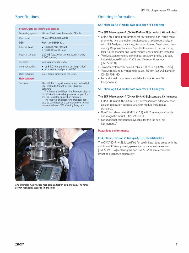
Specifications
SKF Microlog AX provides fast data collection and analysis. The large screen facilitates viewing in any light.
7
SKF Microlog Analyzer AX series
Kit components (included for all kits except as noted)
• CD-ROM, user manuals, utilities, asset information page and
literature
• USB communication / power splitter straight cable, 2 m (6.6 ft.)
[CMAC 5095]
• SD slot cover
• Battery [CMAC 5092]
• Universal power supply [CMAC 5090]
• Carry case [CMAC 5069]
• Soft case [CMAC 5071] 1, 2)
• Two (2) hand straps [CMAC 5072]
• Shoulder strap [CMAC 5073]
• Two (2) screen protectors [CMAC 5074] 1, 2)
• Fischer and audio connector cover set [CMAC 5075]
• 16 GB SD Card [CMAC 5098]
Field upgrades to SKF Microlog AX series
• Frequency Response Function (FRF) module
[CMXA MOD-FRF-SL]
• Run up Coast down module [CMXA MOD-RUCD-SL]
• Data Recorder module [CMXA MOD-REC-SL]
• Conformance Check module [CMXA MOD-CTC-SL]
• Balancing module [CMXA MOD-BAL-SL]
• FFT Analyzer module [CMXA MOD-ANL-SL]
• Spindle Test module, requires Balancing and Run Up Coast down
modules and Spindle accessories [CMXA MOD-MTX-SL]
• SKF Idler Sound Monitor module [CMXA MOD-ISM-SL]
• Route module [CMXA MOD-RTE-SL]
1) Not included in the SKF Microlog AX-A kit.2) Not included in ATEX kit.
SKF Microlog AX series application bundles
• SKF Microlog Balancing kit [CMXA BAL-K-SL]
– Balancing and FFT Analyzer modules
– Accelerometer, small footprint with integrated cable [CMSS 2111]
– Laser tachometer kit [CMAC 5030-K]
– Gooseneck clamp with magnetic base [CMSS 6156]
– Analysis Reporting Manager [CMSW 7311-SL]
• SKF Microlog Spindle Assessment kit [CMXA MTX-K-SL]
– Spindle Test, Balancing and Run up Coast down modules
– Laser tachometer kit [CMAC 5030-K]
– Gooseneck clamp with magnetic base [CMSS 6156]
– Run out gauge [CMAC 5137]
– Belt tension checker [CMAC 5139 and CMAC 5140]
– Spindle test quick start guide
• SKF Microlog Idler Sound Monitor Kit [CMXA ISM-K-SL]
– SKF Idler Sound Monitor and FFT Analyzer modules
– Microphone [CMAC 5091]
– Cable [CMAC 5093]
– Parabola [CMAC 5141]
– Adapter plate [CMAC 5142]
– Wind baffle [CMAC 5143]
– Headphone cable [CMAC 5078]
– Headphone set [CMAC 5403]
– Carrying case [CMAC 5094]
8
SKF Microlog Analyzer AX series
Optional accessories
A number of accessories are available to complement the SKF
Microlog AX. For technical details or information on any item, please
contact your local SKF sales representative. Specifications and pho-
tographs of the SKF Microlog series accessories are available in the
SKF Microlog Analyzer accessories catalog (SKF publication CM/P1
11643 EN).
Hardware
• Triax accelerometer kit [CMAC 4370-K]
• Laser tachometer kit [CMAC 5030-K]
• Laser tachometer kit with ATEX certified tachometer
[CMAC 5030-K-Z2]
• Modal hammer kit for use on structures with a mass of 210 g
(7.6 oz.) and above [CMAC 5056]
• Modal hammer kit for use on structures with a mass of 56 g
(2.0 oz.) and above [CMAC 5057]
• Modal hammer kit without accelerometers [CMAC 5058]
• ICP Microphone with integral preamplifier kit [CMAC 5084]
• AC / DC current clamp [CMAC 5208]
• SKF Microlog Analyzer field balancing accessory kit (with optical
sensor) [CMCP 850-01]
• SKF Microlog Analyzer field balancing accessory kit (with laser
sensor) [CMCP 850-02]
• SKF Microlog Analyzer field balancing accessory kit (with laser
tachometer) [CMCP 850-03]
• Optical phase reference kit [CMSS 6155XK-U-CE]
• Optical phase reference magnetic holder [CMAC 6156]
• Strobe light [CMSS 6165K-AX]
• Smart laser sensor tachometer kit [CMSS 6195AX-K]
Battery and power supply
• Universal power supply [CMAC 5090]
• Battery for use in ATEX and non ATEX units [CMAC 5092]
Accelerometers
• Accelerometer, general purpose, low profile, side exit, industrial,
non-NI, with 1/4-28 and M6 mounting studs [CMSS 2200]
• Accelerometer, general purpose, low profile, side exit, industrial,
non-NI, with M8 mounting stud [CMSS 2200-M8]
• Accelerometer, ATEX approved, IS GPII ICP (100 mVg), general
purpose, industrial [CMSS 793-EE]
• Accelerometer, CSA approved, general purpose, industrial
[CMSS 793-CA]
• Accelerometer, small footprint with integrated cable [CMSS 2111]
• Accelerometer, intrinsically safe (IS) [CMSS 2222]
• High frequency accelerometer kit [CMSS 2114-K]
• Medium duty magnetic base, 35 mm (1.5 in.) diameter
[CMSS 908-MD]
Cables
Accelerometer cables
• Triaxial accelerometer coiled cable [CMAC 5009]
– for use with triax accelerometer kit CMAC 4370-K
• Splitter, four channel, two (2) required [CMAC 5079]
• Accelerometer coiled cable, 1,8 m (6 ft.) [CMAC 5209]
• Accelerometer coiled cable with safety breakaway, 1,8 m (6 ft.)
[CMAC 5209-06S]
• Accelerometer coiled cable, 3 m (10 ft.) [CMAC 5209-10]
Tachometer cables
• BNC tachometer straight cable, 1 m (3.3 ft.) [CMAC 5211]
• Laser tachometer kit, straight cable, 24 cm (9.5 in.) [CMAC 5213]
– for laser tachometer kit CMAC 5030-K (sold with kit only)
• Laser tachometer kit, straight cable, 2 m (6.6 ft.) [CMAC 5214]
– for laser tachometer kit CMAC 5030-K (sold individually)
Extension cables
• CHX signal input straight extension cable, 5 m (16.4 ft.)
[CMAC 5036]
• CHX signal input straight extension cable, 10 m (32.8 ft.)
[CMAC 5037]
• Tachometer straight extension cable, 10 m (32.8 ft.) [CMAC 5044]
– for use with laser tachometer kit CMAC 5030-K
Miscellaneous cables
• Cable converter, two pin MIL to BNC [CMAC 3715]
• USB communication / power splitter straight cable, 2 m (6.6 ft.)
[CMAC 5095]
• Power / trigger splitter straight cable, 30 cm (11.8 in.) [CMAC 5032]
• Fischer to BNC signal input straight cable, lightweight for hammer
kits, 1 m (3.3 ft.) [CMAC 5023]
• Fischer to BNC signal input cable [CMAC 5088]
• Audio headphone straight cable [CMAC 5078]
• USB / A to B straight cable [CMAC 5082]
• Input to strobe light cable [CMAC 5404]
• Output from strobe light cable [CMAC 5406]
Miscellaneous accessories
• Carry case [CMAC 5069]
• Soft case [CMAC 5071]
• Hand strap [CMAC 5072]
• Shoulder strap [CMAC 5073]
• Screen protector [CMAC 5074]
• Fischer and audio connector cover set [CMAC 5075]
• Audio headset, hard hat compatible [CMAC 5403]
• 16 GB SD card [CMAC 5098]
9
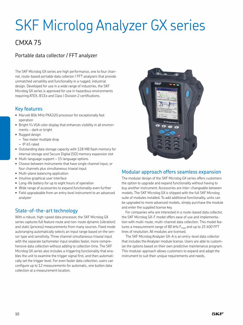
The SKF Microlog GX series are high performance, one to four chan-
nel, route-based portable data collector / FFT analyzers that provide
unmatched versatility and functionality in a rugged, industrial
design. Developed for use in a wide range of industries, the SKF
Microlog GX series is approved for use in hazardous environments
requiring ATEX, IECEx and Class I Division 2 certifications.
Key features• Marvell 806 MHz PXA320 processor for exceptionally fast
operation
• Bright 1/4 VGA color display that enhances visibility in all environ-
ments – dark or bright
• Rugged design
– Two meter multiple drop
– IP 65 rated
• Outstanding data storage capacity with 128 MB flash memory for
internal storage and Secure Digital (SD) memory expansion slot
• Multi-language support – 15 language options
• Choose between instruments that have single channel input, or
four channels plus simultaneous triaxial input
• Multi-plane balancing application
• Intuitive graphical user interface
• Long-life battery for up to eight hours of operation
• Wide range of accessories to expand functionality even further
• Field upgradeable from an entry level instrument to an advanced
analyzer
State-of-the-art technologyWith a robust, high-speed data processor, the SKF Microlog GX
series captures full feature route and non-route dynamic (vibration)
and static (process) measurements from many sources. Fixed mode
autoranging automatically selects an input range based on the sen-
sor type and sensitivity. Three channel simultaneous triaxial input
with the separate tachometer input enables faster, more compre-
hensive data collection without adding to collection time. The SKF
Microlog GX series also includes a triggering functionality that ena-
bles the unit to examine the trigger signal first, and then automati-
cally set the trigger level. For even faster data collection, users can
configure up to 12 measurements for automatic, one button data
collection at a measurement location.
SKF Microlog Analyzer GX series CMXA 75
Portable data collector / FFT analyzer
Modular approach offers seamless expansionThe modular design of the SKF Microlog GX series offers customers
the option to upgrade and expand functionality without having to
buy another instrument. Accessories are inter-changeable between
models. The SKF Microlog GX is shipped with the full SKF Microlog
suite of modules installed. To add additional functionality, units can
be upgraded to more advanced models, simply purchase the module
and enter the supplied license key.
For companies who are interested in a route-based data collector,
the SKF Microlog GX-F model offers ease of use and implementa-
tion with multi-route, multi-channel data collection. This model fea-
tures a measurement range of 80 kHz Fmax and up to 25 600 FFT
lines of resolution. All modules are licensed.
The SKF Microlog Analyzer GX-A is an entry-level data collector
that includes the Analyzer module license. Users are able to custom-
ize the options based on their own predictive maintenance program.
This modular approach allows customers to expand and adapt the
instrument to suit their unique requirements and needs.
10
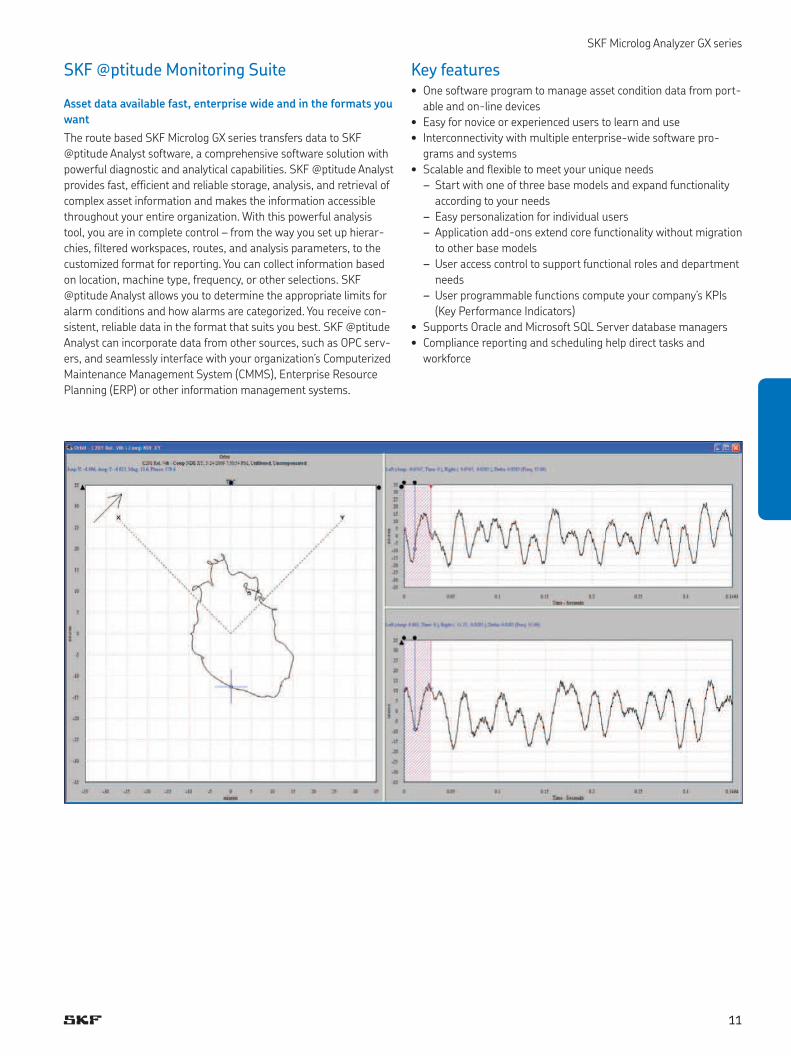
SKF @ptitude Monitoring Suite
Asset data available fast, enterprise wide and in the formats you
want
The route based SKF Microlog GX series transfers data to SKF
@ptitude Analyst software, a comprehensive software solution with
powerful diagnostic and analytical capabilities. SKF @ptitude Analyst
provides fast, efficient and reliable storage, analysis, and retrieval of
complex asset information and makes the information accessible
throughout your entire organization. With this powerful analysis
tool, you are in complete control – from the way you set up hierar-
chies, filtered workspaces, routes, and analysis parameters, to the
customized format for reporting. You can collect information based
on location, machine type, frequency, or other selections. SKF
@ptitude Analyst allows you to determine the appropriate limits for
alarm conditions and how alarms are categorized. You receive con-
sistent, reliable data in the format that suits you best. SKF @ptitude
Analyst can incorporate data from other sources, such as OPC serv-
ers, and seamlessly interface with your organization’s Computerized
Maintenance Management System (CMMS), Enterprise Resource
Planning (ERP) or other information management systems.
Key features• One software program to manage asset condition data from port-
able and on-line devices
• Easy for novice or experienced users to learn and use
• Interconnectivity with multiple enterprise-wide software pro-
grams and systems
• Scalable and flexible to meet your unique needs
– Start with one of three base models and expand functionality
according to your needs
– Easy personalization for individual users
– Application add-ons extend core functionality without migration
to other base models
– User access control to support functional roles and department
needs
– User programmable functions compute your company’s KPIs
(Key Performance Indicators)
• Supports Oracle and Microsoft SQL Server database managers
• Compliance reporting and scheduling help direct tasks and
workforce
SKF Microlog Analyzer GX series
11
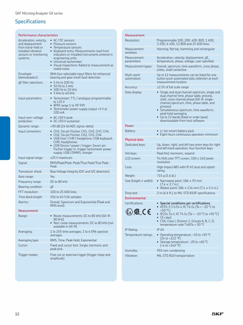
Measurement
Resolution: Programmable 100, 200, 400, 800, 1 600, 3 200, 6 400, 12 800 and 25 600 lines
Measurement windows:
Hanning, flat top, hamming and rectangular
Measurement parameters:
Acceleration, velocity, displacement, gE, temperature, phase, voltage, user specified
Measurement types: Overall, spectrum, time waveform, cross phase, orbits, shaft centerline
Multi-point automation:
Up to 12 meas urements can be listed for one button push automated data collection at each measurement location
Accuracy: ±2.5% of full scale range
Data display: • Single and dual channel spectrum, single and dual channel time, phase table, process, orbit, cross channel phase (GX-R: single-channel spectrum, time, phase table, and process)
• Simultaneous spectrum, time waveform, peak hold averaging
• Up to 12 bands (fixed or order base) downloadable from host software
Power
Battery: • Li-ion smart battery pack• Eight hours continuous operation minimum
Physical data
Dedicated keys: Up, down, right, and left two enter keys for right and left hand operation, four function keys
Hot keys: Peak find, harmonic, expand
LCD screen: 1/4 VGA color TFT screen, 320 ™ 240 pix els resolution
Case: High impact ABS with IP 65 dust and splash rating
Weight: 715 g (1.6 lb.)
Size (height ™ width): • Nar rowest point: 186 ™ 93 mm (7.4 ™ 3.7 in.)
• Widest point: 186 ™ 134 mm (7.4 ™ 5.4 in.)
Drop test: 2 m (6.6 ft.), to MIL STD 810F specifications
Environmental
Certifications: • Special conditions per certifications• ATEX: II 3 G Ex ic IIC T4 Gc (Ta = –10 °C to
+50 °C)• IECEx: Ex ic IIC T4 Gc (Ta = –10 °C to +50 °C)• CE rated• CSA, Class I, Division 2, Groups A, B, C, D,
temperature code T4@Ta = 50 °C
IP Rating: IP 65
Temperature ratings: • Operating temperature: –10 to +50 °C (14 to +122 °F)
• Storage temperature: –20 to +60 °C (–4 to +140 °F)
Humidity: 95% non-condensing
Vibration: MIL STD 810 transportation
SKF Microlog Analyzer GX series
Specifications
Performance characteristics
Acceleration, velocity, and displacement from hand-held or installed vibration sensors or monitoring systems:
• AC / DC sensors• Pressure sensors• Temperature sensors• Keyboard entry: Measurements read from
indicators or installed instruments entered in engineering units
• Universal tachometer• Visual inspections: Added to measurement as
coded notes
Enveloper (demodulator):
With four selectable input filters for enhanced bearing and gear mesh fault detection
gE filter selections: • 5 Hz to 100 Hz• 50 Hz to 1 kHz• 500 Hz to 10 kHz• 5 kHz to 40 kHz
Input parameters: • Tachometer: TTL / analogue programmable to ±25 V
• RPM range 1 to 99 999• Tachometer power supply output +5 V at
100 mA
Input over-voltage protection:
• AC ±50 V peak• DC ±50 V sustained
Dynamic range: >90 dB (24 bit ADC sigma-delta)
Input connectors: • CH1: Six pin Fischer, CH1, CH2, CH3, CH4• CH2: Six pin Fischer, CH2, CH3, CH4• USB host / CHR / headphone: USB keyboard,
CHR, headphones• USB Device / power / trigger: Seven pin
Fischer trigger in, trigger tachometer power supply, USB COMMS, charger
Input signal range: ±25 V maximum
Signal: RMS/Peak/Peak-Peak/True Peak/True Peak-Peak
Transducer check: Bias Voltage Integrity (O/C and S/C detection)
Auto range: Yes
Frequency range: DC to 80 kHz
Bearing condition: gE
FFT resolution: 100 to 25 600 lines
Time block length: 256 to 65 536 samples
Alarms: Overall, Spectrum and Exponential (Peak and RMS level)
Measurement
Range: • Route measurements: DC to 80 kHz (GX-R: 80 kHz)
• Non-route measurements: DC to 80 kHz (not available in GX-R)
Averaging: 1 to 255 time averages, 1 to 4 096 spectral averages
Averaging type: RMS, Time, Peak Hold, Exponential
Cursor: Fixed and cursor lock. Single, har monic and peak pick.
Trigger modes: Free run or external trig ger (trigger slope and amplitude)
12
SKF Microlog Analyzer GX series
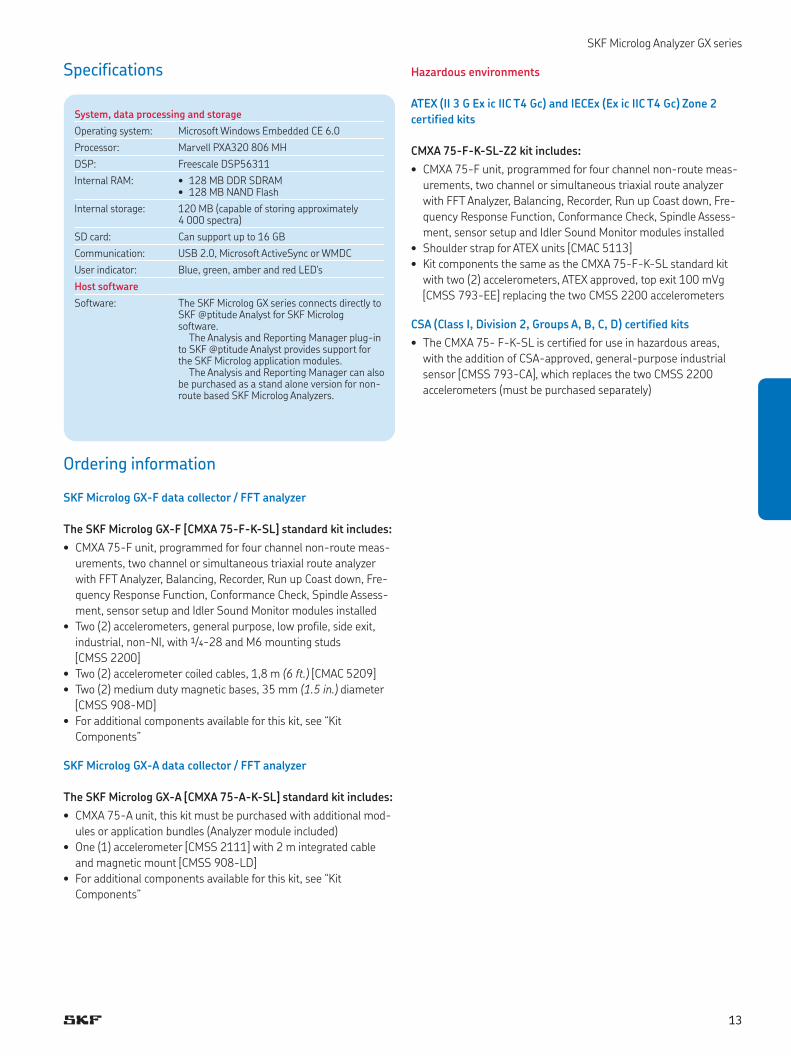
Ordering information
SKF Microlog GX-F data collector / FFT analyzer
The SKF Microlog GX-F [CMXA 75-F-K-SL] standard kit includes:
• CMXA 75-F unit, programmed for four channel non-route meas-
urements, two channel or simultaneous triaxial route analyzer
with FFT Analyzer, Balancing, Recorder, Run up Coast down, Fre-
quency Response Function, Conformance Check, Spindle Assess-
ment, sensor setup and Idler Sound Monitor modules installed
• Two (2) accelerometers, general purpose, low profile, side exit,
industrial, non-NI, with 1/4-28 and M6 mounting studs
[CMSS 2200]
• Two (2) accelerometer coiled cables, 1,8 m (6 ft.) [CMAC 5209]
• Two (2) medium duty magnetic bases, 35 mm (1.5 in.) diameter
[CMSS 908-MD]
• For additional components available for this kit, see “Kit
Components”
SKF Microlog GX-A data collector / FFT analyzer
The SKF Microlog GX-A [CMXA 75-A-K-SL] standard kit includes:
• CMXA 75-A unit, this kit must be purchased with additional mod-
ules or application bundles (Analyzer module included)
• One (1) accelerometer [CMSS 2111] with 2 m integrated cable
and magnetic mount [CMSS 908-LD]
• For additional components available for this kit, see “Kit
Components”
System, data processing and storage
Operating system: Microsoft Windows Embedded CE 6.0
Processor: Marvell PXA320 806 MH
DSP: Freescale DSP56311
Internal RAM: • 128 MB DDR SDRAM• 128 MB NAND Flash
Internal storage: 120 MB (capable of storing approximately 4 000 spectra)
SD card: Can support up to 16 GB
Communication: USB 2.0, Microsoft ActiveSync or WMDC
User indicator: Blue, green, amber and red LED's
Host software
Software: The SKF Microlog GX series connects directly to SKF @ptitude Analyst for SKF Microlog software.
The Analysis and Reporting Manager plug-in to SKF @ptitude Analyst provides support for the SKF Microlog application modules.
The Analysis and Reporting Manager can also be purchased as a stand alone version for non-route based SKF Microlog Analyzers.
Specifications Hazardous environments
ATEX (II 3 G Ex ic IIC T4 Gc) and IECEx (Ex ic IIC T4 Gc) Zone 2
certified kits
CMXA 75-F-K-SL-Z2 kit includes:
• CMXA 75-F unit, programmed for four channel non-route meas-
urements, two channel or simultaneous triaxial route analyzer
with FFT Analyzer, Balancing, Recorder, Run up Coast down, Fre-
quency Response Function, Conformance Check, Spindle Assess-
ment, sensor setup and Idler Sound Monitor modules installed
• Shoulder strap for ATEX units [CMAC 5113]
• Kit components the same as the CMXA 75-F-K-SL standard kit
with two (2) accelerometers, ATEX approved, top exit 100 mVg
[CMSS 793-EE] replacing the two CMSS 2200 accelerometers
CSA (Class I, Division 2, Groups A, B, C, D) certified kits
• The CMXA 75- F-K-SL is certified for use in hazardous areas,
with the addition of CSA-approved, general-purpose industrial
sensor [CMSS 793-CA], which replaces the two CMSS 2200
accelerometers (must be purchased separately)
13
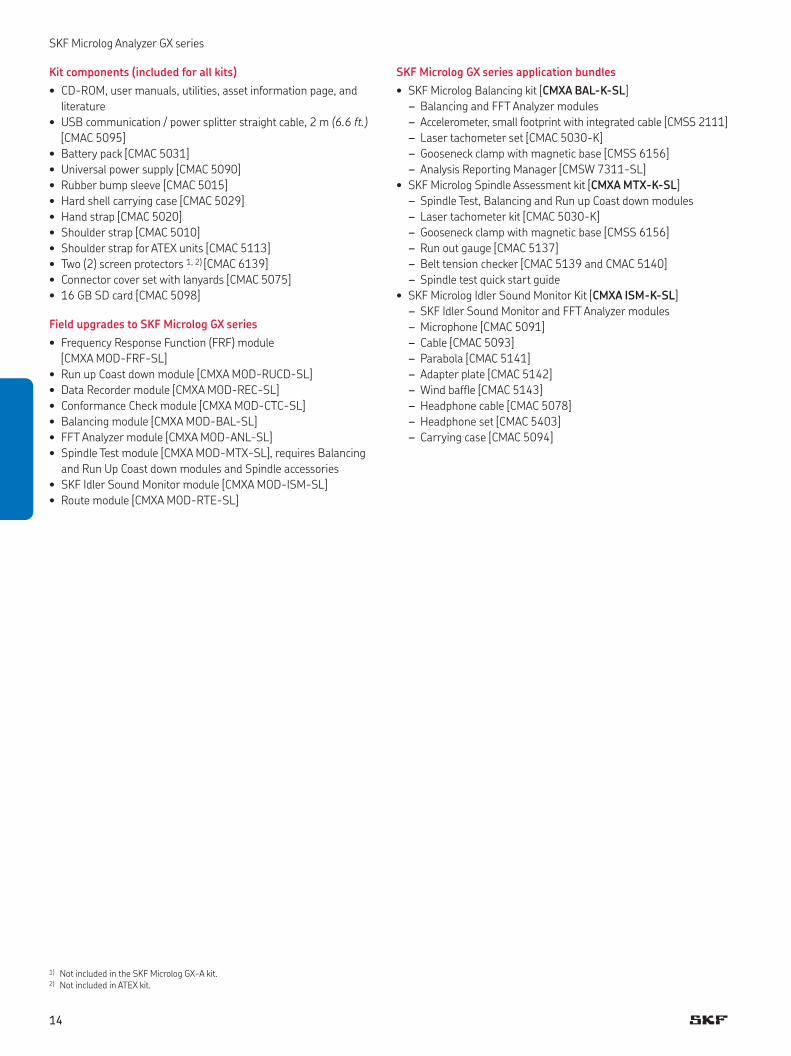
SKF Microlog GX series application bundles
• SKF Microlog Balancing kit [CMXA BAL-K-SL]
– Balancing and FFT Analyzer modules
– Accelerometer, small footprint with integrated cable [CMSS 2111]
– Laser tachometer set [CMAC 5030-K]
– Gooseneck clamp with magnetic base [CMSS 6156]
– Analysis Reporting Manager [CMSW 7311-SL]
• SKF Microlog Spindle Assessment kit [CMXA MTX-K-SL]
– Spindle Test, Balancing and Run up Coast down modules
– Laser tachometer kit [CMAC 5030-K]
– Gooseneck clamp with magnetic base [CMSS 6156]
– Run out gauge [CMAC 5137]
– Belt tension checker [CMAC 5139 and CMAC 5140]
– Spindle test quick start guide
• SKF Microlog Idler Sound Monitor Kit [CMXA ISM-K-SL]
– SKF Idler Sound Monitor and FFT Analyzer modules
– Microphone [CMAC 5091]
– Cable [CMAC 5093]
– Parabola [CMAC 5141]
– Adapter plate [CMAC 5142]
– Wind baffle [CMAC 5143]
– Headphone cable [CMAC 5078]
– Headphone set [CMAC 5403]
– Carrying case [CMAC 5094]
SKF Microlog Analyzer GX series
Kit components (included for all kits)
• CD-ROM, user manuals, utilities, asset information page, and
literature
• USB communication / power splitter straight cable, 2 m (6.6 ft.)
[CMAC 5095]
• Battery pack [CMAC 5031]
• Universal power supply [CMAC 5090]
• Rubber bump sleeve [CMAC 5015]
• Hard shell carrying case [CMAC 5029]
• Hand strap [CMAC 5020]
• Shoulder strap [CMAC 5010]
• Shoulder strap for ATEX units [CMAC 5113]
• Two (2) screen protectors 1, 2) [CMAC 6139]
• Connector cover set with lanyards [CMAC 5075]
• 16 GB SD card [CMAC 5098]
Field upgrades to SKF Microlog GX series
• Frequency Response Function (FRF) module
[CMXA MOD-FRF-SL]
• Run up Coast down module [CMXA MOD-RUCD-SL]
• Data Recorder module [CMXA MOD-REC-SL]
• Conformance Check module [CMXA MOD-CTC-SL]
• Balancing module [CMXA MOD-BAL-SL]
• FFT Analyzer module [CMXA MOD-ANL-SL]
• Spindle Test module [CMXA MOD-MTX-SL], requires Balancing
and Run Up Coast down modules and Spindle accessories
• SKF Idler Sound Monitor module [CMXA MOD-ISM-SL]
• Route module [CMXA MOD-RTE-SL]
1) Not included in the SKF Microlog GX-A kit.2) Not included in ATEX kit.
14
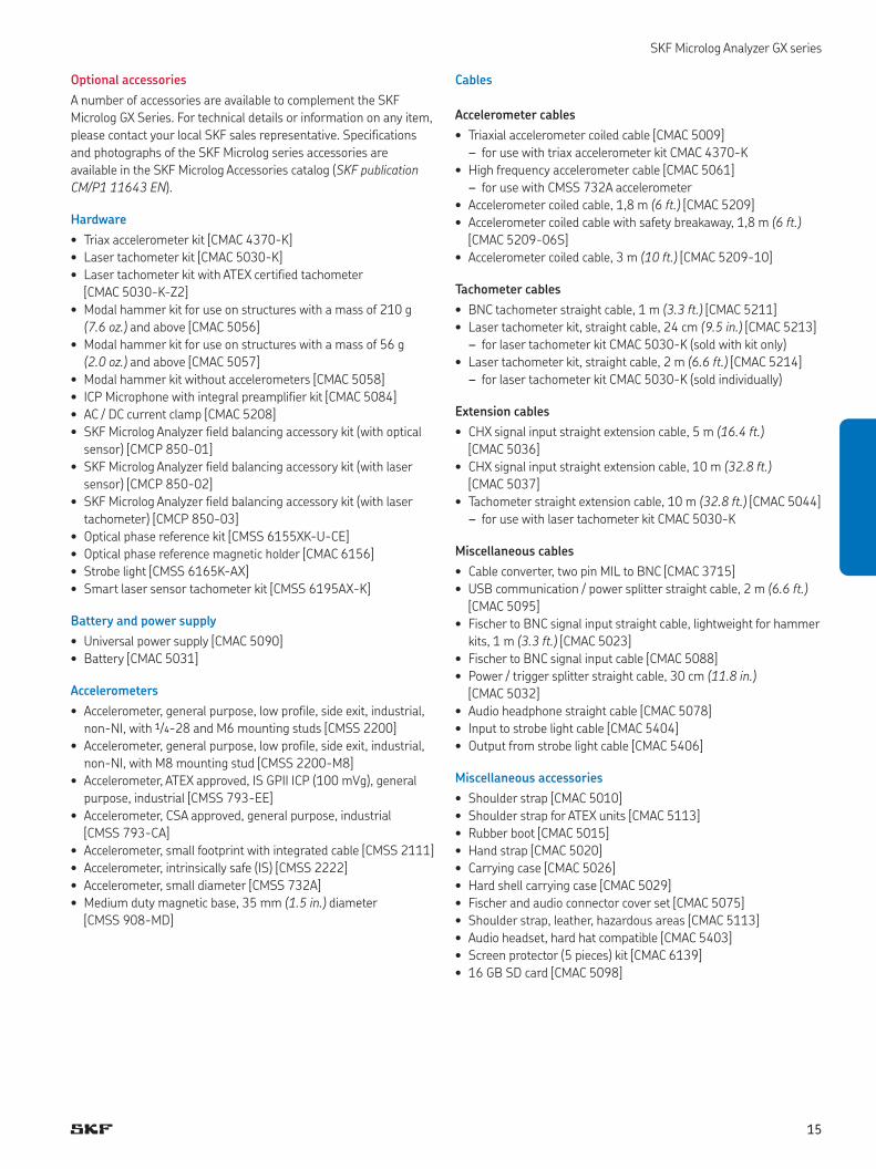
Optional accessories
A number of accessories are available to complement the SKF
Microlog GX Series. For technical details or information on any item,
please contact your local SKF sales representative. Specifications
and photographs of the SKF Microlog series accessories are
available in the SKF Microlog Accessories catalog (SKF publication
CM/P1 11643 EN).
Hardware
• Triax accelerometer kit [CMAC 4370-K]
• Laser tachometer kit [CMAC 5030-K]
• Laser tachometer kit with ATEX certified tachometer
[CMAC 5030-K-Z2]
• Modal hammer kit for use on structures with a mass of 210 g
(7.6 oz.) and above [CMAC 5056]
• Modal hammer kit for use on structures with a mass of 56 g
(2.0 oz.) and above [CMAC 5057]
• Modal hammer kit without accelerometers [CMAC 5058]
• ICP Microphone with integral preamplifier kit [CMAC 5084]
• AC / DC current clamp [CMAC 5208]
• SKF Microlog Analyzer field balancing accessory kit (with optical
sensor) [CMCP 850-01]
• SKF Microlog Analyzer field balancing accessory kit (with laser
sensor) [CMCP 850-02]
• SKF Microlog Analyzer field balancing accessory kit (with laser
tachometer) [CMCP 850-03]
• Optical phase reference kit [CMSS 6155XK-U-CE]
• Optical phase reference magnetic holder [CMAC 6156]
• Strobe light [CMSS 6165K-AX]
• Smart laser sensor tachometer kit [CMSS 6195AX-K]
Battery and power supply
• Universal power supply [CMAC 5090]
• Battery [CMAC 5031]
Accelerometers
• Accelerometer, general purpose, low profile, side exit, industrial,
non-NI, with 1/4-28 and M6 mounting studs [CMSS 2200]
• Accelerometer, general purpose, low profile, side exit, industrial,
non-NI, with M8 mounting stud [CMSS 2200-M8]
• Accelerometer, ATEX approved, IS GPII ICP (100 mVg), general
purpose, industrial [CMSS 793-EE]
• Accelerometer, CSA approved, general purpose, industrial
[CMSS 793-CA]
• Accelerometer, small footprint with integrated cable [CMSS 2111]
• Accelerometer, intrinsically safe (IS) [CMSS 2222]
• Accelerometer, small diameter [CMSS 732A]
• Medium duty magnetic base, 35 mm (1.5 in.) diameter
[CMSS 908-MD]
Cables
Accelerometer cables
• Triaxial accelerometer coiled cable [CMAC 5009]
– for use with triax accelerometer kit CMAC 4370-K
• High frequency accelerometer cable [CMAC 5061]
– for use with CMSS 732A accelerometer
• Accelerometer coiled cable, 1,8 m (6 ft.) [CMAC 5209]
• Accelerometer coiled cable with safety breakaway, 1,8 m (6 ft.)
[CMAC 5209-06S]
• Accelerometer coiled cable, 3 m (10 ft.) [CMAC 5209-10]
Tachometer cables
• BNC tachometer straight cable, 1 m (3.3 ft.) [CMAC 5211]
• Laser tachometer kit, straight cable, 24 cm (9.5 in.) [CMAC 5213]
– for laser tachometer kit CMAC 5030-K (sold with kit only)
• Laser tachometer kit, straight cable, 2 m (6.6 ft.) [CMAC 5214]
– for laser tachometer kit CMAC 5030-K (sold individually)
Extension cables
• CHX signal input straight extension cable, 5 m (16.4 ft.)
[CMAC 5036]
• CHX signal input straight extension cable, 10 m (32.8 ft.)
[CMAC 5037]
• Tachometer straight extension cable, 10 m (32.8 ft.) [CMAC 5044]
– for use with laser tachometer kit CMAC 5030-K
Miscellaneous cables
• Cable converter, two pin MIL to BNC [CMAC 3715]
• USB communication / power splitter straight cable, 2 m (6.6 ft.)
[CMAC 5095]
• Fischer to BNC signal input straight cable, lightweight for hammer
kits, 1 m (3.3 ft.) [CMAC 5023]
• Fischer to BNC signal input cable [CMAC 5088]
• Power / trigger splitter straight cable, 30 cm (11.8 in.)
[CMAC 5032]
• Audio headphone straight cable [CMAC 5078]
• Input to strobe light cable [CMAC 5404]
• Output from strobe light cable [CMAC 5406]
Miscellaneous accessories
• Shoulder strap [CMAC 5010]
• Shoulder strap for ATEX units [CMAC 5113]
• Rubber boot [CMAC 5015]
• Hand strap [CMAC 5020]
• Carrying case [CMAC 5026]
• Hard shell carrying case [CMAC 5029]
• Fischer and audio connector cover set [CMAC 5075]
• Shoulder strap, leather, hazardous areas [CMAC 5113]
• Audio headset, hard hat compatible [CMAC 5403]
• Screen protector (5 pieces) kit [CMAC 6139]
• 16 GB SD card [CMAC 5098]
SKF Microlog Analyzer GX series
15
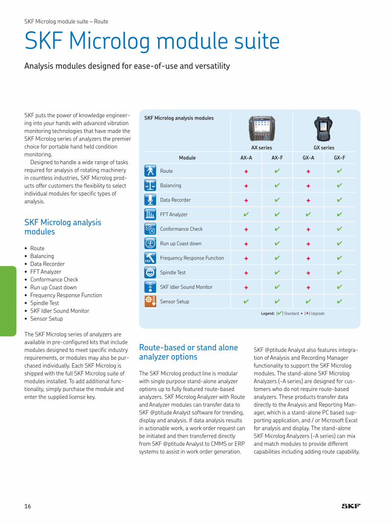
SKF puts the power of knowledge engineer-
ing into your hands with advanced vibration
monitoring technologies that have made the
SKF Microlog series of analyzers the premier
choice for portable hand held condition
monitoring.
Designed to handle a wide range of tasks
required for analysis of rotating machinery
in countless industries, SKF Microlog prod-
ucts offer customers the flexibility to select
individual modules for specific types of
analysis.
SKF Microlog analysis modules
• Route
• Balancing
• Data Recorder
• FFT Analyzer
• Conformance Check
• Run up Coast down
• Frequency Response Function
• Spindle Test
• SKF Idler Sound Monitor
• Sensor Setup
The SKF Microlog series of analyzers are
available in pre-configured kits that include
modules designed to meet specific industry
requirements, or modules may also be pur-
chased individually. Each SKF Microlog is
shipped with the full SKF Microlog suite of
modules installed. To add additional func-
tionality, simply purchase the module and
enter the supplied license key.
Route-based or stand alone analyzer options
The SKF Microlog product line is modular
with single purpose stand-alone analyzer
options up to fully featured route-based
analyzers. SKF Microlog Analyzer with Route
and Analyzer modules can transfer data to
SKF @ptitude Analyst software for trending,
display and analysis. If data analysis results
in actionable work, a work order request can
be initiated and then transferred directly
from SKF @ptitude Analyst to CMMS or ERP
systems to assist in work order generation.
SKF Microlog module suiteAnalysis modules designed for ease-of-use and versatility
SKF Microlog analysis modules
AX series GX series
Module AX-A AX-F GX-A GX-F
Route + 3 + 3
Balancing + 3 + 3
Data Recorder + 3 + 3
FFT Analyzer 3 3 3 3
Conformance Check + 3 + 3
Run up Coast down + 3 + 3
Frequency Response Function + 3 + 3
Spindle Test + 3 + 3
SKF Idler Sound Monitor + 3 + 3
Sensor Setup 3 3 3 3
Legend: (3) Standard • (+) Upgrade
SKF @ptitude Analyst also features integra-
tion of Analysis and Recording Manager
functionality to support the SKF Microlog
modules. The stand-alone SKF Microlog
Analyzers (-A series) are designed for cus-
tomers who do not require route-based
analyzers. These products transfer data
directly to the Analysis and Reporting Man-
ager, which is a stand-alone PC based sup-
porting application, and / or Microsoft Excel
for analysis and display. The stand-alone
SKF Microlog Analyzers (-A series) can mix
and match modules to provide different
capabilities including adding route capability.
SKF Microlog module suite – Route
16
Route
Route based data collection for your plant based maintenance program
Trending vibration data from critical and non-critical machines in
your plant is essential to reduce unplanned downtime and mainte-
nance costs. The SKF Microlog Analyzer "Route" module allows users
to carry out routine data collection, using a multi-parameter
approach, to collect and trend data to help diagnose machinery
faults. Users can set up single channel, dual or simultaneous triaxial
measurements using SKF @ptitude Analyst software. Your SKF
@ptitude Analyst host software's ROUTE feature allows you to build
measurement collection sequences (ROUTEs) to help users perform
the most efficient data collection. SKF Microlog ROUTE data collec-
tion is a very easy process, in fact, once you begin data collection,
you need only press the Enter button repeatedly to sequentially col-
lect data for every measurement POINT in your ROUTE.
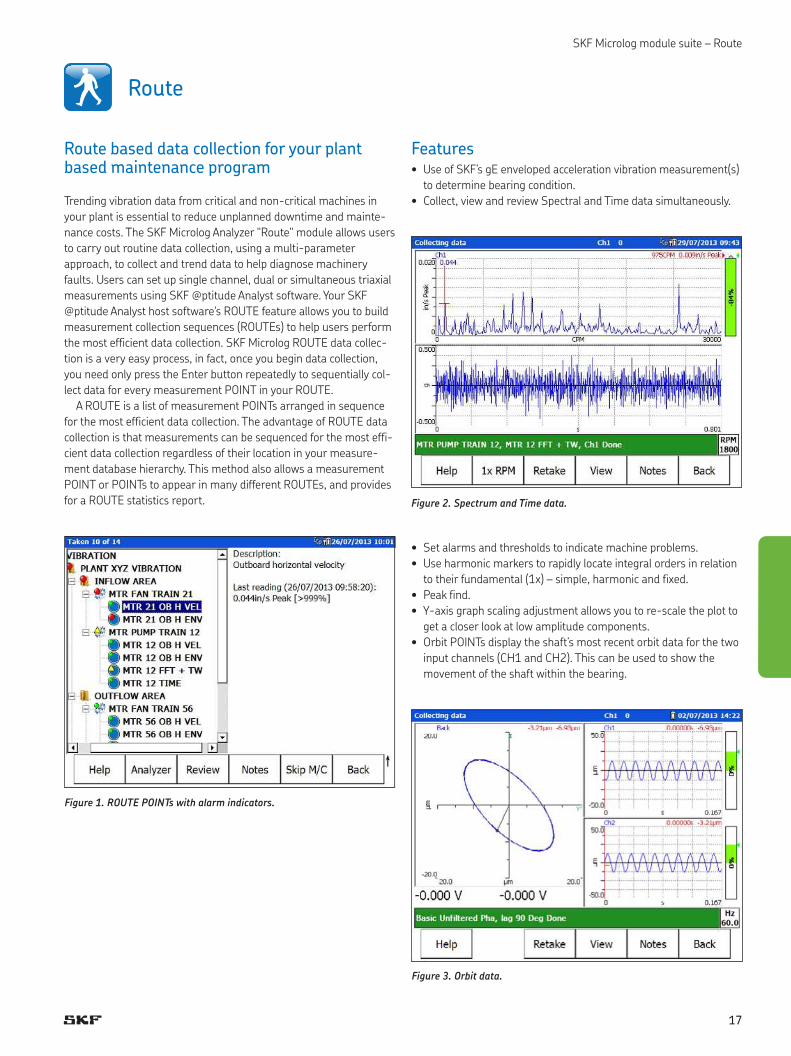
A ROUTE is a list of measurement POINTs arranged in sequence
for the most efficient data collection. The advantage of ROUTE data
collection is that measurements can be sequenced for the most effi-
cient data collection regardless of their location in your measure-
ment database hierarchy. This method also allows a measurement
POINT or POINTs to appear in many different ROUTEs, and provides
for a ROUTE statistics report.
Figure 1. ROUTE POINTs with alarm indicators.
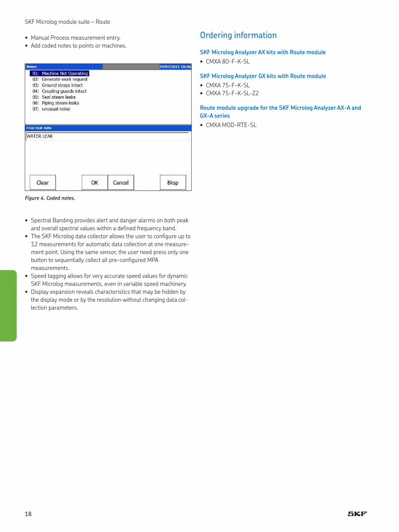
Features• Use of SKF’s gE enveloped acceleration vibration measurement(s)
to determine bearing condition.
• Collect, view and review Spectral and Time data simultaneously.
• Set alarms and thresholds to indicate machine problems.
• Use harmonic markers to rapidly locate integral orders in relation
to their fundamental (1x) – simple, harmonic and fixed.
• Peak find.
• Y-axis graph scaling adjustment allows you to re-scale the plot to
get a closer look at low amplitude components.
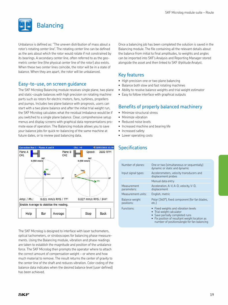
• Orbit POINTs display the shaft’s most recent orbit data for the two
input channels (CH1 and CH2). This can be used to show the
movement of the shaft within the bearing.
Figure 2. Spectrum and Time data.
Figure 3. Orbit data.
SKF Microlog module suite – Route
17
SKF Microlog module suite – Route
Ordering information
SKF Microlog Analyzer AX kits with Route module
• CMXA 80-F-K-SL
SKF Microlog Analyzer GX kits with Route module
• CMXA 75-F-K-SL
• CMXA 75-F-K-SL-Z2
Route module upgrade for the SKF Microlog Analyzer AX-A and
GX-A series
• CMXA MOD-RTE-SL
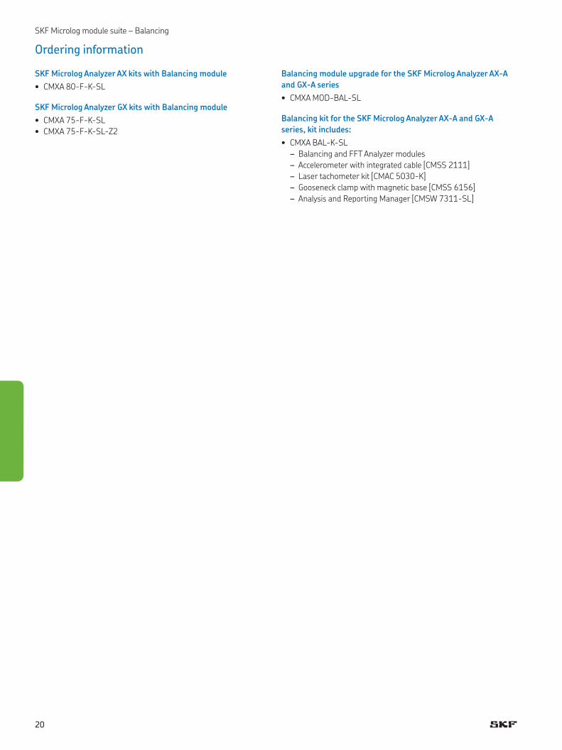
• Manual Process measurement entry.
• Add coded notes to points or machines.
• Spectral Banding provides alert and danger alarms on both peak
and overall spectral values within a defined frequency band.
• The SKF Microlog data collector allows the user to configure up to
12 measurements for automatic data collection at one measure-
ment point. Using the same sensor, the user need press only one
button to sequentially collect all pre-configured MPA
measurements.
• Speed tagging allows for very accurate speed values for dynamic
SKF Microlog measurements, even in variable speed machinery.
• Display expansion reveals characteristics that may be hidden by
the display mode or by the resolution without changing data col-
lection parameters.
Figure 4. Coded notes.
18
SKF Microlog module suite – Route
Balancing
Unbalance is defined as: “The uneven distribution of mass about a
rotor’s rotating center line”. The rotating center line can be defined
as the axis about which the rotor would rotate if not constrained by
its bearings. A secondary center line, often referred to as the geo-
metric center line (the physical center line of the rotor) also exists.
When these two center lines coincide, the rotor will be in a state of
balance. When they are apart, the rotor will be unbalanced.
Easy-to-use, on screen guidanceThe SKF Microlog Balancing module resolves single plane, two plane
and static-couple balances with high precision on rotating machine
parts such as rotors for electric motors, fans, turbines, propellers
and pumps. Includes two plane balance with prognosis, users can
start with a two plane balance and after the initial trial weight run,
the SKF Microlog calculates what the residual imbalance would be if
you switched to a single plane balance. Clear, comprehensive setup
menus and display screens with graphical data representations pro-
mote ease of operation. The Balancing module allows you to save
your balance jobs for quick re-balancing of the same machine at
future dates, or to review past balancing data.
The SKF Microlog is designed to interface with laser tachometers,
optical tachometers, or stroboscopes for balancing phase measure-
ments. Using the Balancing module, vibration and phase readings
are taken to establish the magnitude and position of the unbalance
force. The SKF Microlog then prompts the operator where to attach
the correct amount of compensation weight – or where and how
much material to remove. The result returns the center of gravity to
the center line of the shaft and reduces vibration. Color coding of the
balance data indicates when the desired balance level (user defined)
has been achieved.
Once a balancing job has been completed the solution is saved in the
Balancing module. The file containing all the relevant details about
the balance from initial to final amplitudes, to weights and angles
can be imported into SKF’s Analysis and Reporting Manager stored
alongside the asset and then linked to SKF @ptitude Analyst.
Key features• High precision one or two plane balancing
• Balance both slow and fast rotating machines
• Ability to resolve balance weights and trial weight estimator
• Easy to follow interface with graphical outputs
Benefits of properly balanced machinery• Minimize structural stress
• Minimize vibration
• Reduced noise levels
• Increased machine and bearing life
• Increased safety
• Lower operating costs
Specifications
Number of planes: One or two (simultaneous or sequentially) dynamic or static and dynamic
Input signal types: Accelerometers, velocity transducers and displacement probes
Manual data entry
Measurement parameters:
Acceleration, A-V, A-D, velocity, V-D, displacement
Measurement units: English, metric
Balance weight positions:
Polar (360°), fixed component (for fan blades, etc.)
Functions: • Fixed weights and vibration levels• Trial weight calculator• Save partially completed runs• Fix position of resultant weight location as
number of positions/angle for fan balancing
19
SKF Microlog module suite – Balancing
Ordering information
SKF Microlog Analyzer AX kits with Balancing module
• CMXA 80-F-K-SL
SKF Microlog Analyzer GX kits with Balancing module
• CMXA 75-F-K-SL
• CMXA 75-F-K-SL-Z2
Balancing module upgrade for the SKF Microlog Analyzer AX-A
and GX-A series
• CMXA MOD-BAL-SL
Balancing kit for the SKF Microlog Analyzer AX-A and GX-A
series, kit includes:
• CMXA BAL-K-SL
– Balancing and FFT Analyzer modules
– Accelerometer with integrated cable [CMSS 2111]
– Laser tachometer kit [CMAC 5030-K]
– Gooseneck clamp with magnetic base [CMSS 6156]
– Analysis and Reporting Manager [CMSW 7311-SL]
20
SKF Microlog module suite – Data Recorder
Data Recorder
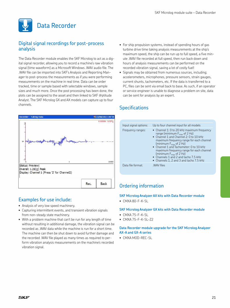
Digital signal recordings for post-process analysis
The Data Recorder module enables the SKF Microlog to act as a dig-
ital signal recorder, allowing you to record a machine’s raw vibration
signal (time waveform) as a Microsoft Windows .WAV audio file. The
.WAV file can be imported into SKF’s Analysis and Reporting Man-
ager to post-process the measurements as if you were performing
measurements on the machine in real time. Data can be order
tracked, time or sample based with selectable windows, sample
sizes and much more. Once the post processing has been done, the
plots can be assigned to the asset and then linked to SKF @ptitude
Analyst. The SKF Microlog GX and AX models can capture up to four
channels.
Examples for use include:• Analysis of very low speed machinery.
• Capturing intermittent events, and transient vibration signals
from non-steady state machinery.
• With a problem machine that can’t be run for any length of time
without resulting in additional damage, the vibration signal can be
recorded as .WAV data while the machine is run for a short time.
The machine can then be shut down to avoid further damage and
the recorded .WAV file played as many times as required to per-
form vibration analysis measurements on the machine’s recorded
vibration signal.
• For ship propulsion systems, instead of spending hours of gas
turbine drive time taking analysis measurements at the ship’s
maximum speed, the ship can be run up to full speed, a five min-
ute .WAV file recorded at full speed, then run back down and
hours of analysis measurements can be performed on the
recorded vibration signal, saving a lot of costly fuel!
• Signals may be obtained from numerous sources, including;
accelerometers, microphones, pressure sensors, strain gauges,
current shunts, tachometers, etc. If the data is transferred to a
PC, files can be sent via email back to base. As such, if an operator
or service engineer is unable to diagnose a problem on site, data
can be sent for analysis by an expert.
Specifications
Input signal options: Up to four channel input for all models
Frequency ranges: • Channel 1: 0 to 20 kHz maximum frequency range (minimum Fmax of 2 Hz)
• Channel 1 and Channel 2: 0 to 10 kHz maximum frequency range for each channel (minimum Fmax of 2 Hz)
• Channel 1 and Tachometer: 0 to 10 kHz maximum frequency range for each channel (minimum Fmax of 2 Hz)
• Channels 1 and 2 and tacho 7.5 kHz• Channels 1, 2 and 3 and tacho 7.5 kHz
Data file format: .WAV files
Ordering information
SKF Microlog Analyzer AX kits with Data Recorder module
• CMXA 80-F-K-SL
SKF Microlog Analyzer GX kits with Data Recorder module
• CMXA 75-F-K-SL
• CMXA 75-F-K-SL-Z2
Data Recorder module upgrade for the SKF Microlog Analyzer
AX-A and GX-A series
• CMXA MOD-REC-SL
21
SKF Microlog module suite – FFT Analyzer
FFT Analyzer (Including Bump Test functionality)
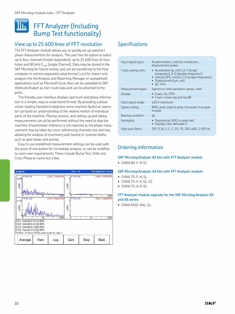
View up to 25 600 lines of FFT resolutionThe FFT Analyzer module allows you to quickly set up spectral /
phase measurements for analysis. The user has the option to select
up to four channels (model dependent), up to 25 600 lines of reso-
lution and 80 kHz Fmax (single Channel). Data may be stored in the
SKF Microlog for future review, and can be transferred to the host
computer in comma separated value format (.csv) for import and
analysis into the Analysis and Reporting Manager or spreadsheet
applications such as Microsoft Excel. Also can be uploaded to SKF
@ptitude Analyst as non-route data and can be attached to the
point.
The friendly user interface displays spectrum and phase informa-
tion in a simple, easy to understand format. By providing a phase
vector reading (needed to diagnose some machine faults) an opera-
tor can build an understanding of the relative motion of individual
parts of the machine. Placing sensors, and setting up and taking
measurements can all be performed without the need to stop the
machine. A tachometer reference is not required as the phase meas-
urement may be taken by cross-referencing channels one and two,
allowing for analysis of machinery with buried or covered shafts,
such as gear boxes and pumps.
Easy to use predefined measurement settings can be used with
the press of one button for immediate analysis, or can be modified
to users own requirements. These include Bump Test, Orbit and
Cross Phase to name but a few.
Specifications
Input signal types: Accelerometers, velocity transducers, displacement probes
Y axis scaling units: • Acceleration (g, m/s2), A-V (single integration), A-D (double integration)
• Velocity (IPS, mm/s), V-D (single integration)• Displacement (μm, mil)• gE, time
Measurement types: Spectrum, time waveform, phase, orbit
Display: • X axis: Hz, CPM• Y axis: Linear, log and log dB
Input signal range: ±25 V maximum
Signal scaling: RMS, peak, peak to peak, true peak, true peak to peak
Bearing condition: gE
Averaging: • Exponential, RMS or peak hold• Overlap: User definable %
High pass filters: Off / 0,36, 1,1, 2, 10. 70, 200, 600, 2 500 Hz
Ordering information
SKF Microlog Analyzer AX kits with FFT Analyzer module
• CMXA 80-F-K-SL
SKF Microlog Analyzer GX kits with FFT Analyzer module
• CMXA 75-F-K-SL
• CMXA 75-F-K-SL-Z2
• CMXA 75-A-K-SL
FFT Analzyer module upgrade for the SKF Microlog Analyzer AX
and GX series
• CMXA MOD-ANL-SL
22
SKF Microlog module suite – Conformance Check
The Conformance Check module transforms the SKF Microlog into a
tool for inspection and maintenance. An automated assessment
compares vibration levels with established limits and a pass or fail
indication is displayed to show whether the product complies with
predefined quality indicators or required standards. Conformance
Check has the ability to assess up to 64 individual fault criteria
simultaneously and provide an on-screen indication if a warning or
alarm level is reached.
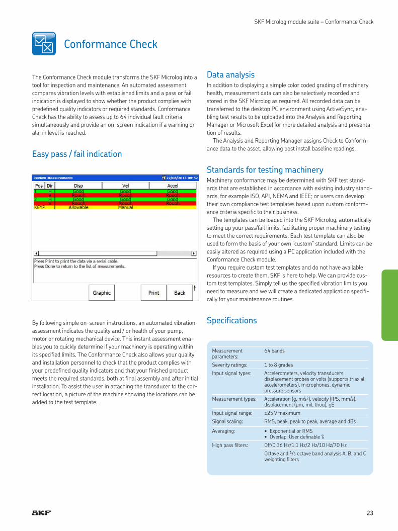
Easy pass / fail indication
By following simple on-screen instructions, an automated vibration
assessment indicates the quality and / or health of your pump,
motor or rotating mechanical device. This instant assessment ena-
bles you to quickly determine if your machinery is operating within
its specified limits. The Conformance Check also allows your quality
and installation personnel to check that the product complies with
your predefined quality indicators and that your finished product
meets the required standards, both at final assembly and after initial
installation. To assist the user in attaching the transducer to the cor-
rect location, a picture of the machine showing the locations can be
added to the test template.
Data analysisIn addition to displaying a simple color coded grading of machinery
health, measurement data can also be selectively recorded and
stored in the SKF Microlog as required. All recorded data can be
transferred to the desktop PC environment using ActiveSync, ena-
bling test results to be uploaded into the Analysis and Reporting
Manager or Microsoft Excel for more detailed analysis and presenta-
tion of results.
The Analysis and Reporting Manager assigns Check to Conform-
ance data to the asset, allowing post install baseline readings.
Standards for testing machineryMachinery conformance may be determined with SKF test stand-
ards that are established in accordance with existing industry stand-
ards, for example ISO, API, NEMA and IEEE; or users can develop
their own compliance test templates based upon custom conform-
ance criteria specific to their business.
The templates can be loaded into the SKF Microlog, automatically
setting up your pass/fail limits, facilitating proper machinery testing
to meet the correct requirements. Each test template can also be
used to form the basis of your own “custom” standard. Limits can be
easily altered as required using a PC application included with the
Conformance Check module.
If you require custom test templates and do not have available
resources to create them, SKF is here to help. We can provide cus-
tom test templates. Simply tell us the specified vibration limits you
need to measure and we will create a dedicated application specifi-
cally for your maintenance routines.
Specifications
Measurement parameters:
64 bands
Severity ratings: 1 to 8 grades
Input signal types: Accelerometers, velocity transducers, displacement probes or volts (supports triaxial accelerometers), microphones, dynamic pressure sensors
Measurement types: Acceleration (g, m/s2), velocity (IPS, mm/s), displacement (μm, mil, thou), gE
Input signal range: ±25 V maximum
Signal scaling: RMS, peak, peak to peak, average and dBs
Averaging: • Exponential or RMS• Overlap: User definable %
High pass filters: Off/0,36 Hz/1,1 Hz/2 Hz/10 Hz/70 Hz
Octave and 1/3 octave band analysis A, B, and C weighting filters
Conformance Check
23
Ordering information
SKF Microlog Analyzer AX kits with Conformance Check module
• CMXA 80-F-K-SL
SKF Microlog Analyzer GX kits with Conformance Check module
• CMXA 75-F-K-SL
• CMXA 75-F-K-SL-Z2
Conformance Check module upgrade for the SKF Microlog
Analyzer AX and GX series
• CMXA MOD-CTC-SL
SKF Microlog module suite – Conformance Check
24
SKF Microlog module suite – Run up Coast down
Run up Coast down
Specifications
Ordering information
SKF Microlog Analyzer AX kits with Run up Coast Down module
• CMXA 80-F-K-SL
SKF Microlog Analyzer GX kits with Run up Coast Down module
• CMXA 75-F-K-SL
• CMXA 75-F-K-SL-Z2
Run up Coast Down module upgrade for the SKF Microlog
Analyzer AX and GX series
• CMXA MOD-RUCD-SL
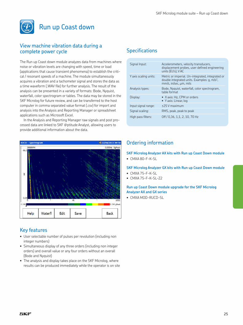
View machine vibration data during a complete power cycle
The Run up Coast down module analyzes data from machines where
noise or vibration levels are changing with speed, time or load
(applications that cause transient phenomena) to establish the criti-
cal / resonant speeds of a machine. The module simultaneously
acquires a vibration and a tachometer signal and stores the data as
a time waveform (.WAV file) for further analysis. The result of the
analysis can be presented in a variety of formats: Bode, Nyquist,
waterfall, color spectrogram or tables. The data may be stored in the
SKF Microlog for future review, and can be transferred to the host
computer in comma separated value format (.csv) for import and
analysis into the Analysis and Reporting Manager or spreadsheet
applications such as Microsoft Excel.
In the Analysis and Reporting Manager raw signals and post pro-
cessed data are linked to SKF @ptitude Analyst, allowing users to
provide additional information about the data.
Key features• User selectable number of pulses per revolution (including non
integer numbers)
• Simultaneous display of any three orders (including non integer
orders) and overall value or any four orders without an overall
(Bode and Nyquist)
• The analysis and display takes place on the SKF Microlog, where
results can be produced immediately while the operator is on site
Signal Input: Accelerometers, velocity transducers, displacement probes, user defined engineering units (EU’s), V AC
Y axis scaling units: Metric or imperial. Un-integrated, integrated or double integrated units. Examples: g, m/s2, mm/s, in/sec, μm, mils
Analysis types: Bode, Nyquist, waterfall, color spectrogram, table format
Display: • X axis: Hz, CPM or orders• Y axis: Linear, log
Input signal range: ±25 V maximum
Signal scaling: RMS, peak, peak to peak
High pass filters: Off / 0,36, 1,1, 2, 10, 70 Hz
25
SKF Microlog module suite – Frequency Response Function
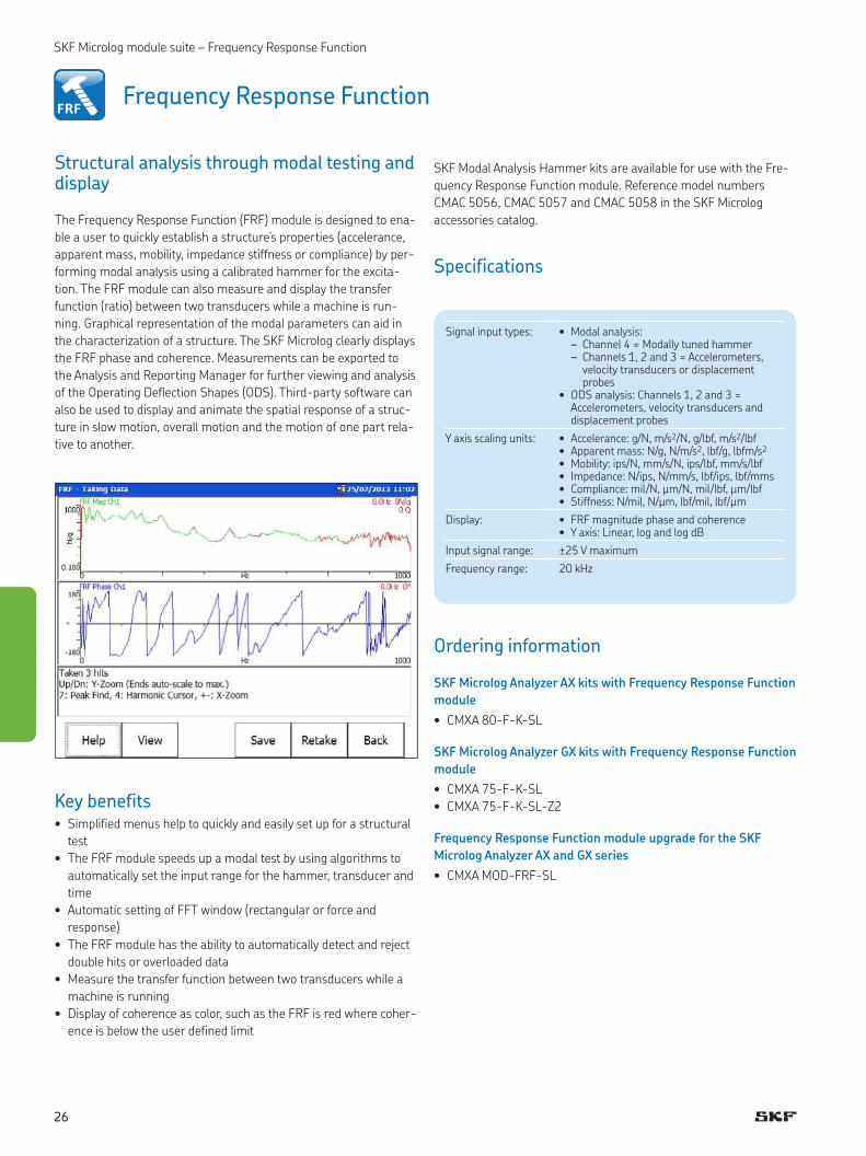
Structural analysis through modal testing and display
The Frequency Response Function (FRF) module is designed to ena-
ble a user to quickly establish a structure’s properties (accelerance,
apparent mass, mobility, impedance stiffness or compliance) by per-
forming modal analysis using a calibrated hammer for the excita-
tion. The FRF module can also measure and display the transfer
function (ratio) between two transducers while a machine is run-
ning. Graphical representation of the modal parameters can aid in
the characterization of a structure. The SKF Microlog clearly displays
the FRF phase and coherence. Measurements can be exported to
the Analysis and Reporting Manager for further viewing and analysis
of the Operating Deflection Shapes (ODS). Third-party software can
also be used to display and animate the spatial response of a struc-
ture in slow motion, overall motion and the motion of one part rela-
tive to another.
Key benefits• Simplified menus help to quickly and easily set up for a structural
test
• The FRF module speeds up a modal test by using algorithms to
automatically set the input range for the hammer, transducer and
time
• Automatic setting of FFT window (rectangular or force and
response)
• The FRF module has the ability to automatically detect and reject
double hits or overloaded data
• Measure the transfer function between two transducers while a
machine is running
• Display of coherence as color, such as the FRF is red where coher-
ence is below the user defined limit
Frequency Response Function
SKF Modal Analysis Hammer kits are available for use with the Fre-
quency Response Function module. Reference model numbers
CMAC 5056, CMAC 5057 and CMAC 5058 in the SKF Microlog
accessories catalog.
Specifications
Ordering information
SKF Microlog Analyzer AX kits with Frequency Response Function
module
• CMXA 80-F-K-SL
SKF Microlog Analyzer GX kits with Frequency Response Function
module
• CMXA 75-F-K-SL
• CMXA 75-F-K-SL-Z2
Frequency Response Function module upgrade for the SKF
Microlog Analyzer AX and GX series
• CMXA MOD-FRF-SL
Signal input types: • Modal analysis: – Channel 4 = Modally tuned hammer – Channels 1, 2 and 3 = Accelerometers, velocity transducers or displacement probes
• ODS analysis: Channels 1, 2 and 3 = Accelerometers, velocity transducers and displacement probes
Y axis scaling units: • Accelerance: g/N, m/s2/N, g/lbf, m/s2/lbf• Apparent mass: N/g, N/m/s2, lbf/g, lbfm/s2
• Mobility: ips/N, mm/s/N, ips/lbf, mm/s/lbf• Impedance: N/ips, N/mm/s, lbf/ips, lbf/mms• Compliance: mil/N, μm/N, mil/lbf, μm/lbf• Stiffness: N/mil, N/μm, lbf/mil, lbf/μm
Display: • FRF magnitude phase and coherence• Y axis: Linear, log and log dB
Input signal range: ±25 V maximum
Frequency range: 20 kHz
26
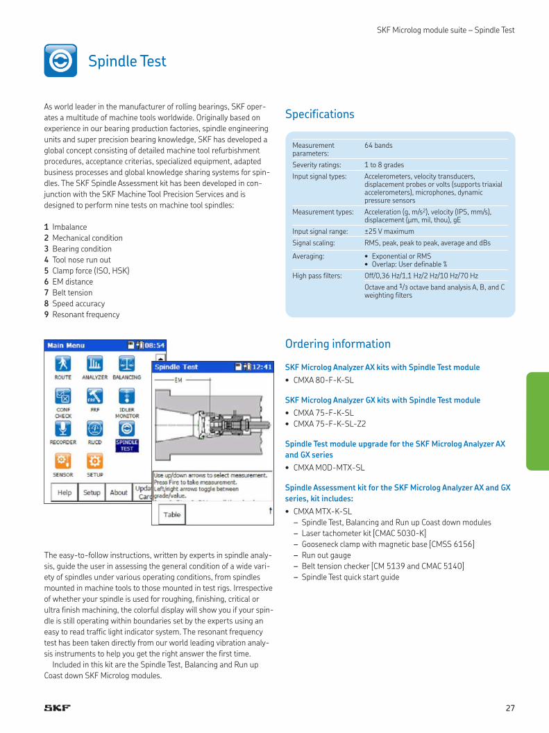
SKF Microlog module suite – Spindle Test
As world leader in the manufacturer of rolling bearings, SKF oper-
ates a multitude of machine tools worldwide. Originally based on
experience in our bearing production factories, spindle engineering
units and super precision bearing knowledge, SKF has developed a
global concept consisting of detailed machine tool refurbishment
procedures, acceptance criterias, specialized equipment, adapted
business processes and global knowledge sharing systems for spin-
dles. The SKF Spindle Assessment kit has been developed in con-
junction with the SKF Machine Tool Precision Services and is
designed to perform nine tests on machine tool spindles:
1 Imbalance
2 Mechanical condition
3 Bearing condition
4 Tool nose run out
5 Clamp force (ISO, HSK)
6 EM distance
7 Belt tension
8 Speed accuracy
9 Resonant frequency
The easy-to-follow instructions, written by experts in spindle analy-
sis, guide the user in assessing the general condition of a wide vari-
ety of spindles under various operating conditions, from spindles
mounted in machine tools to those mounted in test rigs. Irrespective
of whether your spindle is used for roughing, finishing, critical or
ultra finish machining, the colorful display will show you if your spin-
dle is still operating within boundaries set by the experts using an
easy to read traffic light indicator system. The resonant frequency
test has been taken directly from our world leading vibration analy-
sis instruments to help you get the right answer the first time.
Included in this kit are the Spindle Test, Balancing and Run up
Coast down SKF Microlog modules.
Spindle Test
Specifications
Ordering information
SKF Microlog Analyzer AX kits with Spindle Test module
• CMXA 80-F-K-SL
SKF Microlog Analyzer GX kits with Spindle Test module
• CMXA 75-F-K-SL
• CMXA 75-F-K-SL-Z2
Spindle Test module upgrade for the SKF Microlog Analyzer AX
and GX series
• CMXA MOD-MTX-SL
Spindle Assessment kit for the SKF Microlog Analyzer AX and GX
series, kit includes:
• CMXA MTX-K-SL
– Spindle Test, Balancing and Run up Coast down modules
– Laser tachometer kit [CMAC 5030-K]
– Gooseneck clamp with magnetic base [CMSS 6156]
– Run out gauge
– Belt tension checker [CM 5139 and CMAC 5140]
– Spindle Test quick start guide
Measurement parameters:
64 bands
Severity ratings: 1 to 8 grades
Input signal types: Accelerometers, velocity transducers, displacement probes or volts (supports triaxial accelerometers), microphones, dynamic pressure sensors
Measurement types: Acceleration (g, m/s2), velocity (IPS, mm/s), displacement (μm, mil, thou), gE
Input signal range: ±25 V maximum
Signal scaling: RMS, peak, peak to peak, average and dBs
Averaging: • Exponential or RMS• Overlap: User definable %
High pass filters: Off/0,36 Hz/1,1 Hz/2 Hz/10 Hz/70 Hz
Octave and 1/3 octave band analysis A, B, and C weighting filters
27
SKF Microlog module suite – SKF Idler Sound Monitor
Detect conveyor idler faults with the SKF Microlog Idler Sound Monitor kit
In many industries, conveyors are an important part of a material
handling system especially in mining and cement industries. Failure
of an idler can lead to belt damage, expensive downtime and lost
production. The SKF Idler Sound Monitor Kit was developed for early
detection of faults in conveyor support and return idlers. Using
acoustic enveloping technology, the SKF Idler Sound Monitor Kit dis-
tinguishes between the sounds of a good idler and a faulty one. It
can detect faulty idlers earlier and more reliably than, for instance,
when a maintenance worker walks the length of the conveyor belt to
listen or look for problems. The kit also provides shorter measure-
ment time and earlier fault detection than a thermographic camera.
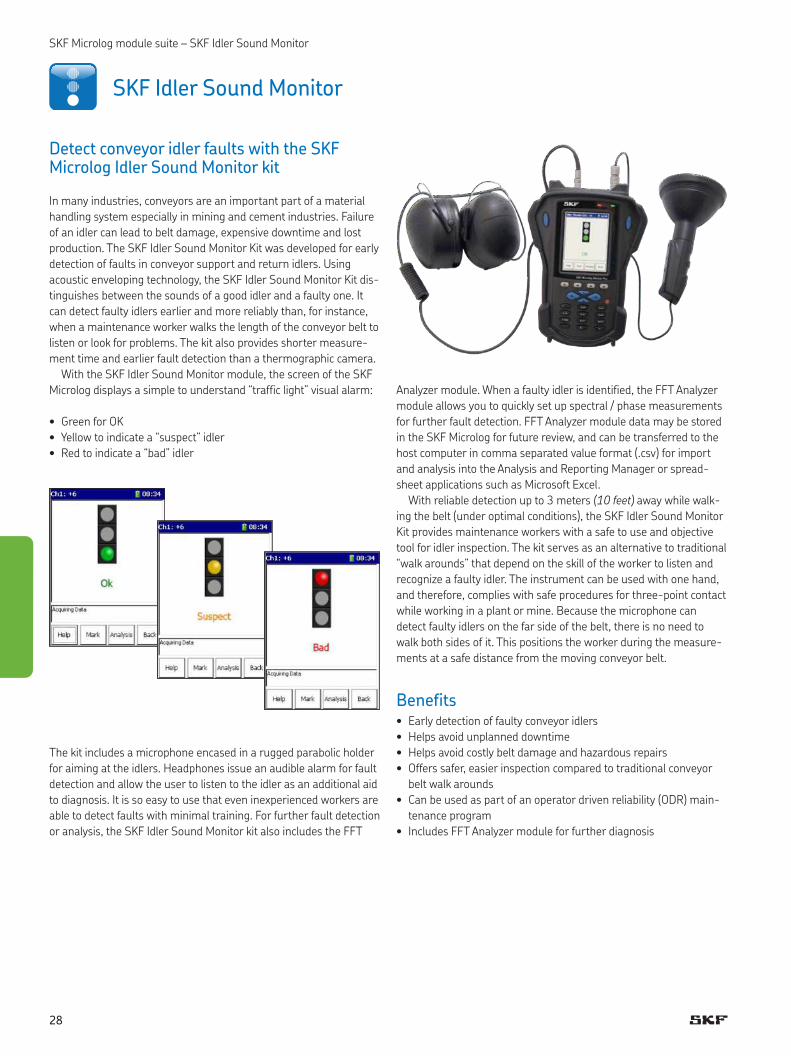
With the SKF Idler Sound Monitor module, the screen of the SKF
Microlog displays a simple to understand “traffic light” visual alarm:
• Green for OK
• Yellow to indicate a “suspect” idler
• Red to indicate a “bad” idler
The kit includes a microphone encased in a rugged parabolic holder
for aiming at the idlers. Headphones issue an audible alarm for fault
detection and allow the user to listen to the idler as an additional aid
to diagnosis. It is so easy to use that even inexperienced workers are
able to detect faults with minimal training. For further fault detection
or analysis, the SKF Idler Sound Monitor kit also includes the FFT
Analyzer module. When a faulty idler is identified, the FFT Analyzer
module allows you to quickly set up spectral / phase measurements
for further fault detection. FFT Analyzer module data may be stored
in the SKF Microlog for future review, and can be transferred to the
host computer in comma separated value format (.csv) for import
and analysis into the Analysis and Reporting Manager or spread-
sheet applications such as Microsoft Excel.
With reliable detection up to 3 meters (10 feet) away while walk-
ing the belt (under optimal conditions), the SKF Idler Sound Monitor
Kit provides maintenance workers with a safe to use and objective
tool for idler inspection. The kit serves as an alternative to traditional
“walk arounds” that depend on the skill of the worker to listen and
recognize a faulty idler. The instrument can be used with one hand,
and therefore, complies with safe procedures for three-point contact
while working in a plant or mine. Because the microphone can
detect faulty idlers on the far side of the belt, there is no need to
walk both sides of it. This positions the worker during the measure-
ments at a safe distance from the moving conveyor belt.
Benefits• Early detection of faulty conveyor idlers
• Helps avoid unplanned downtime
• Helps avoid costly belt damage and hazardous repairs
• Offers safer, easier inspection compared to traditional conveyor
belt walk arounds
• Can be used as part of an operator driven reliability (ODR) main-
tenance program
• Includes FFT Analyzer module for further diagnosis
SKF Idler Sound Monitor
28

SKF Microlog module suite – SKF Idler Sound Monitor
Measurement overviewSKF Idler Sound Monitor “listens” to each roller’s sound and simulta-
neously applies four acoustic measurements that are preset to best
detect idler faults for typical conveyor conditions. These measure-
ments are set up to monitor the types of sound emitted by conveyor
idler rollers and filter out other unwanted sounds. The four tech-
niques used to analyze data and detect faults are:
1 gE True Peak
– Detect impact
type vibration
2 gE Root Sum
Square (RSS)
overall
– Detect overall
magnitude of
impact
vibration
3 Kurtosis
– Detect whether
vibration signal
is a hiss,
crackle,
rumbling
4 Harmonic Activity
Indicator (HAI)
– Bearing har-
monic activity
In addition to the simple traffic light display, customers also have the
option to display each measurement value.
Ordering information
SKF Microlog Analyzer AX kits with SKF Idler Sound Monitor
module
• CMXA 80-F-K-SL
SKF Microlog Analyzer GX kits with SKF Idler Sound Monitor
module
• CMXA 75-F-K-SL
• CMXA 75-F-K-SL-Z2
Idler Sound Monitor upgrade for the SKF Microlog Analyzer AX-A
and GX-A series
• CMXA MOD-ISM-SL
SKF Microlog Analyzer Idler Sound Monitor kit [CMXA ISM-K-SL]
consists of:
• SKF Idler Sound Monitor module [CMXA MOD-ISM-SL]
• FFT Analyzer module [CMXA MOD-ANL-SL]
• Parabolic reflector [CMAC 5141]
• Adapter plate assembly [CMAC 5142]
• Parabolic windjammer [CMAC 5143]
• Microphone [CMAC 5091]
• Audio headphones, hard hat compatible [CMAC 5403]
• Audio headphone cable [CMAC 5078]
• Cable [CMAC 5093]
• Carrying case [CMAC 5094]
Software options
• The SKF Idler Sound Monitor data can be transferred to the host
computer in comma separated value format (.csv) for import into
spreadsheet applications such as Microsoft Excel or into Microsoft
Word tables.
29
SKF Microlog module suite – Sensor Setup
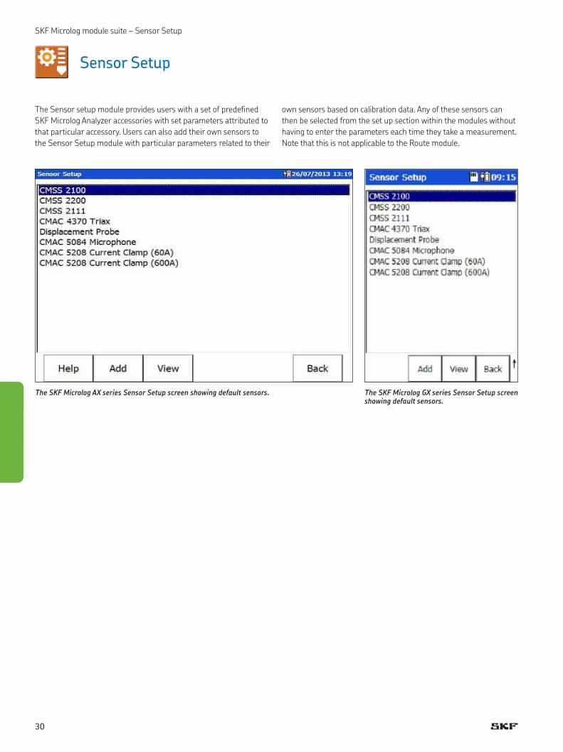
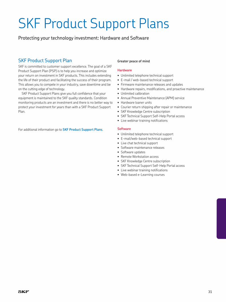
The Sensor setup module provides users with a set of predefined
SKF Microlog Analyzer accessories with set parameters attributed to
that particular accessory. Users can also add their own sensors to
the Sensor Setup module with particular parameters related to their
Sensor Setup
The SKF Microlog AX series Sensor Setup screen showing default sensors. The SKF Microlog GX series Sensor Setup screen showing default sensors.
own sensors based on calibration data. Any of these sensors can
then be selected from the set up section within the modules without
having to enter the parameters each time they take a measurement.
Note that this is not applicable to the Route module.
30
SKF Product Support PlansProtecting your technology investment: Hardware and Software
Greater peace of mind
Hardware
• Unlimited telephone technical support
• E-mail / web-based technical support
• Firmware maintenance releases and updates
• Hardware repairs, modifications, and proactive maintenance
• Unlimited calibration
• Annual Preventive Maintenance (APM) service
• Hardware loaner units
• Courier return shipping after repair or maintenance
• SKF Knowledge Centre subscription
• SKF Technical Support Self-Help Portal access
• Live webinar training notifications
Software
• Unlimited telephone technical support
• E-mail/web-based technical support
• Live chat technical support
• Software maintenance releases
• Software updates
• Remote Workstation access
• SKF Knowledge Centre subscription
• SKF Technical Support Self-Help Portal access
• Live webinar training notifications
• Web-based e-Learning courses
SKF Product Support PlanSKF is committed to customer support excellence. The goal of a SKF
Product Support Plan (PSP) is to help you increase and optimize
your return on investment in SKF products. This includes extending
the life of their product and facilitating the success of their program.
This allows you to compete in your industry, save downtime and be
on the cutting edge of technology.
SKF Product Support Plans give you full confidence that your
equipment is maintained to the SKF quality standards. Condition
monitoring products are an investment and there is no better way to
protect your investment for years than with a SKF Product Support
Plan.
For additional information go to SKF Product Support Plans.
31
Please contact:
SKF USA Inc.Condition Monitoring Center – Livingston2 Michaelson Square, Kirkton Campus • Livingston, West LothianEH54 7DP s • United KingdomTel: +44 (0) 1506 470011 • Fax: +44 (0) 1506 470012
Web: www.skf.com/cm
® SKF, @PTITUDE, MICROLOG, and MULTILOG are registered trademarks of the SKF Group.
Bluetooth is a registered trademark of Bluetooth SIG, Inc.
ICP is a registered trademark of PCB Group, Inc.
Intel and Intel XScale are registered trademarks of Intel Corporation in the United States and other countries.
Marvell is a registered trademark of Marvell or its affiliates.
Microsoft, Windows, ActiveSync, Excel, PowerPoint, SQL Server, Windows Server and Windows Vista are either registered trademarks or trademarks of Microsoft Corporation in the United States and / or other countries.
Oracle is a registered trademark of Oracle Corporation.
All other trademarks are the property of their respective owners.
© SKF Group 2020The contents of this publication are the copyright of the publisher and may not be reproduced (even extracts) unless prior written permission is granted. Every care has been taken to ensure the accuracy of the information contained in this publication, but no liability can be accepted for any loss or damage whether direct, indirect or consequential arising out of the use of the information contained herein. SKF reserves the right to alter any part of this publication without prior notice.
Patents: US 4,768,380 · US 5,633,811 · US 5,679,900 · US 5,845,230 · US 5,852,351 · US 5,854,553 · US 5,854,994 · US 5,870,699 · US 5,907,491 · US 5,992,237 · US 6,006,164 · US 6,124,692 · US 6,138,078 · US 6,199,422 · US 6,202,491 · US 6,275,781 · US 6,301,514 · US 6,437,692 · US 6,489,884 · US 6,513,386 · US 6,633,822 · US 6,789,025 · US 6,792,360 · US 7,103,511 · US 7,697,492 · WO/2003/048714
PUB CM/P1 14285/9 EN · March 2020
skf.com