title of presentation - university of vermontyzhang19/publications/presentation/gpr_trb_2014... ·...
TRANSCRIPT

Tian XiaSchool of EngineeringUniversity of Vermont

Motivation
GPR System development
- System Architecture
- GPR Signal Processing
Experimental results
Conclusions
2

Subsurface structure inspection is highly demanded but challenging.
Subsurface Defects: Cavity; Fouled railroad ballast; High degree moisture.
Traditional inspection methods: drilling test and acoustic/hammer test etc. - destructive, low efficiency, low coverage, time consuming, and disturbing to normal traffic.
Ground Penetrating Radar (GPR) Non-destructive; Easy deployment; High efficiency;
3

Subsurface medias of different dielectric constants different EM waves attenuation and travel time;
The reflected EM signals can be used for subsurface condition characterizations.
4

To develop a new GPR to accomplish high inspection performance for railroad subsurface structure characterizations;
Targeted Features: Air-launched GPR; Enable high speed survey: up to 60 mph; Fine high resolution: 1 cm;
Wide area coverage – parallel lanes inspection; Good penetrating capability – 3 feet depth;
5

6

• System and Environmental Noise Removal Ensemble Averaging
• Image Resolution Improvement Bicubic Interpolation Algorithm
• Signal Attenuation Compensation Adaptive Gain Adjustment
• Signal Envelope Extracting Hilbert Transform
• Background Removal Average Subtracting Filter
7

Experimental Results
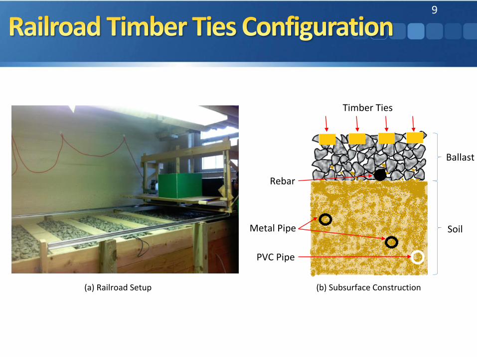
• Railroad Timber Ties and Subsurface Pipes Configuration
• Ballast Contamination Configuration
19
9
Ballast
Soil
Timber Ties
Rebar
Metal Pipe
PVC Pipe
(a) Railroad Setup (b) Subsurface Construction

(a) Raw B-scan (b) Interpolation + Adaptive Gain Enhancement
(c) Background Removal
Four Timber Ties
Rebar
Two Metal Pipes
PVC Pipe
Direct Coupling
Air-Ballast Surface
Ballast-Soil Surface
21

11
• Comparative experiments containing dry ballast, fouled ballast and moisten fouled ballast are shown in Figure (a), (b) and (c) respectively.
• For dry ballast setup, clean ballasts are used to fill a large test hole that is 2 feet long, 1 foot wide and 3 inches deep.
• For fouled ballast setup, clean ballasts are mixed with soil and sand.
• For moisten fouled ballast setup, water is added to the fouled ballast layer.

23
• Different ballast condition can be characterized through measuring ballast reflection signal power, which varies due to the size difference of air voids in ballast of different fouling conditions.• Clean ballast: large air voids; stronger scattering effect;
high reflection signal power• Fouled ballast: small air voids; weak scattering effect and
reflection signal power• Moisten fouled ballast: scattering and reflection signal
power is further reduced.• Hilbert Transform is applied to extract ballast layer reflection
signal power information.

24
• In each image, (a) is the raw B-Scan image, (b) is processed B-Scan image, and (c) is the normalized energy map
• For dry and clean ballast, the normalized energy of ballast area is close to 1
• For fouled ballast, the normalized energy of ballast area is 0.9
• For moisten fouled ballast, the normalized energy is only 0.5
• These quantitative power parameters are consistent with the theoretical analysis based on the ballast structure
Dry Ballast
Fouled Ballast
Moisten Fouled Ballast

25
A new air-launched UWB GPR is developed to facilitate railroad timber ties location and subsurface ballast condition inspection.
The development of both hardware and signal processing algorithms are elaborated.
The laboratory experiments validate the system operation and its effectiveness for subsurface object detection and ballast fouling condition assessment.

Thanks !