transport and main roads specifications mrts87 supply of timber
TRANSCRIPT

Technical Specification Transport and Main Roads Specifications MRTS87 Supply of Timber Bridge Materials and Components July 2017

Transport and Main Roads Specifications, July 2017
Copyright
http://creativecommons.org/licenses/by/3.0/au/
© State of Queensland (Department of Transport and Main Roads) 2017
Feedback: Please send your feedback regarding this document to: [email protected]

Transport and Main Roads Specifications, July 2017 i
Contents
1 Introduction ....................................................................................................................................1
2 Definition of terms .........................................................................................................................1
3 Referenced documents .................................................................................................................1
4 Quality system requirements .......................................................................................................2
4.1 Hold Points, Witness Points and Milestones .................................................................................. 2
5 Objectives of this Technical Specification ..................................................................................2
6 Materials and components ...........................................................................................................3
6.1 Supply of components .................................................................................................................... 3
6.2 Components supplied by the Principal ........................................................................................... 3 6.2.1 Supply location ...............................................................................................................3 6.2.2 Time of delivery ..............................................................................................................3 6.2.3 Acceptance of components by the Contractor ...............................................................3 6.2.4 Damage to components .................................................................................................3
6.3 Proprietary products ....................................................................................................................... 3
6.4 Storage ........................................................................................................................................... 3
6.5 Hardwood timber ............................................................................................................................ 4 6.5.1 Scope .............................................................................................................................4 6.5.2 Nomenclature .................................................................................................................4 6.5.3 Selection of timber ..........................................................................................................4 6.5.4 Inspection .......................................................................................................................7 6.5.5 Sawn timber ....................................................................................................................7 6.5.6 Round timber ..................................................................................................................8 6.5.7 Preservative treatment ...................................................................................................9 6.5.8 Delivery and stacking .................................................................................................. 10
6.6 Structural plywood ........................................................................................................................ 10 6.6.1 Scope .......................................................................................................................... 10 6.6.2 Nomenclature .............................................................................................................. 10 6.6.3 Material properties ....................................................................................................... 10 6.6.4 Component design ...................................................................................................... 11 6.6.5 Component fabrication ................................................................................................ 11 6.6.6 Preservative treatment ................................................................................................ 11 6.6.7 Inspection .................................................................................................................... 11 6.6.8 Delivery and stacking .................................................................................................. 12
6.7 Precast prestressed concrete bridge decking .............................................................................. 12 6.7.1 Scope .......................................................................................................................... 12 6.7.2 Component design ...................................................................................................... 12 6.7.3 Component supply and storage .................................................................................. 12
6.8 Steel bridge decking ..................................................................................................................... 13 6.8.1 Scope .......................................................................................................................... 13 6.8.2 Component design ...................................................................................................... 13 6.8.3 Component installation ................................................................................................ 13 6.8.4 Component supply and storage .................................................................................. 13
6.9 Fibre reinforced polymer composite girders ................................................................................. 13
Appendix A – List of definitions ........................................................................................................ 14
Appendix B – Timber species growing areas ................................................................................... 19
Appendix C – Standard headstock dimensions* ............................................................................. 21
Appendix D – Acceptable untreated sapwood ................................................................................. 23

Transport and Main Roads Specifications, July 2017 ii
Appendix E(A) – Species selection flowchart .................................................................................. 24
Appendix E(B) – Worked examples – timber selection ................................................................... 25
Appendix F – Octagonal sawn girders .............................................................................................. 26
Appendix G – Deck and kerb profiles ................................................................................................ 30
Technical Specification, MRTS87 Supply of Timber Bridge Materials and Components
Transport and Main Roads Specifications, July 2017 1
1 Introduction
This Technical Specification applies to the supply of materials and components used in the construction and / or maintenance of bridges built either wholly or partially with timber materials.
This Technical Specification shall be read in conjunction with MRTS01 Introduction to Technical Specifications, MRTS50 Specific Quality System Requirements and other Technical Specifications as appropriate.
This Technical Specification forms part of the Transport and Main Roads Specifications Manual.
2 Definition of terms
The terms used in this Technical Specification are as defined in Appendix A to this Technical Specification.
Further definitions are included in Clause 2 of MRTS01 Introduction to Technical Specifications.
3 Referenced documents
Table 3 lists documents referenced in this Technical Specification.
Table 3 – Referenced documents
Reference Title
AS 1397 Steel sheet and strip - Hot-dipped zinc-coated or aluminium/zinc-coated
AS 1604.1 Specification for Preservative Treatment Part 1: Sawn and Round Timber
AS 2082 Timber – Hardwood -Visually Stress – Graded for Structural Purposes
AS 3818.1 Timber – Heavy Structural Products – Visually Graded. Part 1: General Requirements
AS 3818.11 Timber – Heavy Structural Products – Visually Graded. Part 11: Utility Poles
AS 3818.3 Timber – Heavy Structural Products – Visually Graded. Part 3: Piles
AS/NZS 1148 Timber – Nomenclature – Australian, New Zealand and Imported Species
AS/NZS 1604.3 Specification for Preservative Treatment. Part 3: Plywood
AS/NZS 2269 Plywood – Structural
AS/NZS 4491 Timber – Glossary of Terms in Timber Related Standards
AS/NZS 4680 Hot-dip galvanized (zinc) coatings on fabricated ferrous articles
C6827 Principal Supplied Material List
MRTS01 Introduction to Technical Specifications
MRTS50 Specific Quality System Requirements
MRTS59 Manufacture of Fibre Reinforced Polymer (FRP) Composite Girders
MRTS60 Installation of Fibre Reinforced Polymer (FRP) Composite Girders
MRTS70 Concrete
MRTS72 Manufacture of Precast Concrete Elements
MRTS73 Manufacture of Prestressed Concrete Members and Stressing Units
MRTS78 Fabrication of Structural Steelwork
- Timber Bridge Maintenance Manual – Transport and Main Roads

Technical Specification, MRTS87 Supply of Timber Bridge Materials and Components
Transport and Main Roads Specifications, July 2017 2
4 Quality system requirements
4.1 Hold Points, Witness Points and Milestones
General requirements for Hold Points, Witness Points and Milestones are specified in Clause 5.2 of MRTS01 Introduction to Technical Specifications.
The Hold Points and Milestones applicable to this Technical Specification are summarised in Table 4.1.There are no Witness Points defined.
Table 4.1 – Hold Points, Witness Points and Milestones
Clause Hold Point Witness Point Milestone
6.5.3 1. Approval of alternative hardwood timber species
Submit request for alternative species (14 days)
6.5.4 2. Pre-delivery inspection of hardwood materials and components
Inspection by nominated representative (5 days)
6.5.7.1 3. Verification of compliance with preservative treatment requirements – hardwood timber
6.6.4 4. Approval of proposed alternative decking details using alternative materials – plywood
Submit request for alternative decking approval to Administrator (28 days)
6.6.6 5. Verification of compliance with preservative treatment requirements – plywood
6.6.7 Inspection by nominated representative (five days)
6.7.2 6. Approval of proposed alternative decking details using alternative materials –prestressed concrete components
Submit request for alternative decking approval to Administrator (28 days)
6.8.2 7. Approval of proposed alternative decking details using alternative materials –steel
Submit request for alternative decking approval to Administrator (28 days)
6.8.4 Inspection by nominated representative (5 days)
5 Objectives of this Technical Specification
The objectives of this Technical Specification are:
a) to ensure that timber to be used for the various bridge components is selected to satisfy both structural strength and durability requirements, and
b) to ensure that the department’s standards follow philosophies similar to existing and proposed Australian Standards, while retaining the traditional empirical practices of earlier specifications.
Technical Specification, MRTS87 Supply of Timber Bridge Materials and Components
Transport and Main Roads Specifications, July 2017 3
6 Materials and components
6.1 Supply of components
Where listed in the Principal Supplied Materials List (Form C6827), components shall be supplied by the Principal.
Where not so listed, components shall be supplied by the Contractor.
6.2 Components supplied by the Principal
6.2.1 Supply location
Components supplied by the Principal will be made available at the point of delivery and by the transport mode shown in the Principal Supplied Materials List (Form C6827).
6.2.2 Time of delivery
The time of delivery shall generally conform to the construction program supplied with the Contractor’s tender documents.
6.2.3 Acceptance of components by the Contractor
The Contractor shall check the components for quantity and condition upon taking delivery and shall immediately report to the Administrator any defect or deficiency.
6.2.4 Damage to components
In the event of a component sustaining damage after the item has been inspected by the Contractor, the item shall be set aside until it has been inspected by the Administrator.
The cost of repairs or replacement of rejected components shall be borne by the Contractor.
6.3 Proprietary products
Proprietary products covered by this specification include thick structural plywood decking, precast prestressed concrete bridge decking, steel bridge decking and fibre reinforced polymer composite girders.
Where proprietary products are scheduled to be supplied by the Contractor, it shall be the Contractor’s responsibility to guarantee and, if requested, submit evidence that the product shall be satisfactory, structurally adequate, durable and safe for the intended purpose and also complies with all relevant federal, state and local government regulations, laws and standards and Australian Standards (if applicable).
In particular, the Contractor shall be responsible for ensuring that any structural (or load bearing) component or product has been designed by a practising Structural Engineer to accommodate all the loadings, and that the component / product has been constructed in accordance with that design. A full set of auditable design calculations shall be made available for perusal if requested by the Administrator.
6.4 Storage
Storage of components at the Site shall be carried out to the requirements stated in this Technical Specification for the various materials and components.
Technical Specification, MRTS87 Supply of Timber Bridge Materials and Components
Transport and Main Roads Specifications, July 2017 4
6.5 Hardwood timber
6.5.1 Scope
Clause 6.5 sets out details and requirements for the supply and delivery of hardwood timber for bridges.
Where possible, the requirements of the relevant Australian Standard have been used. Where specifically noted, requirements of this Technical Specification shall take precedence over such requirements.
6.5.2 Nomenclature
For the purpose of this Technical Specification, the standard trade common names and botanical names of the timbers as listed in AS/NZS 1148 shall be used.
Common alternative names have also been included for reference.
Appendix A to this Technical Specification includes a list of definitions applied to timber materials and components.
The terms “heartwood”, “truewood” and “redwood” have been used synonymously by the department in various documents. The terminology which shall be used for this Technical Specification is “heartwood”.
6.5.3 Selection of timber
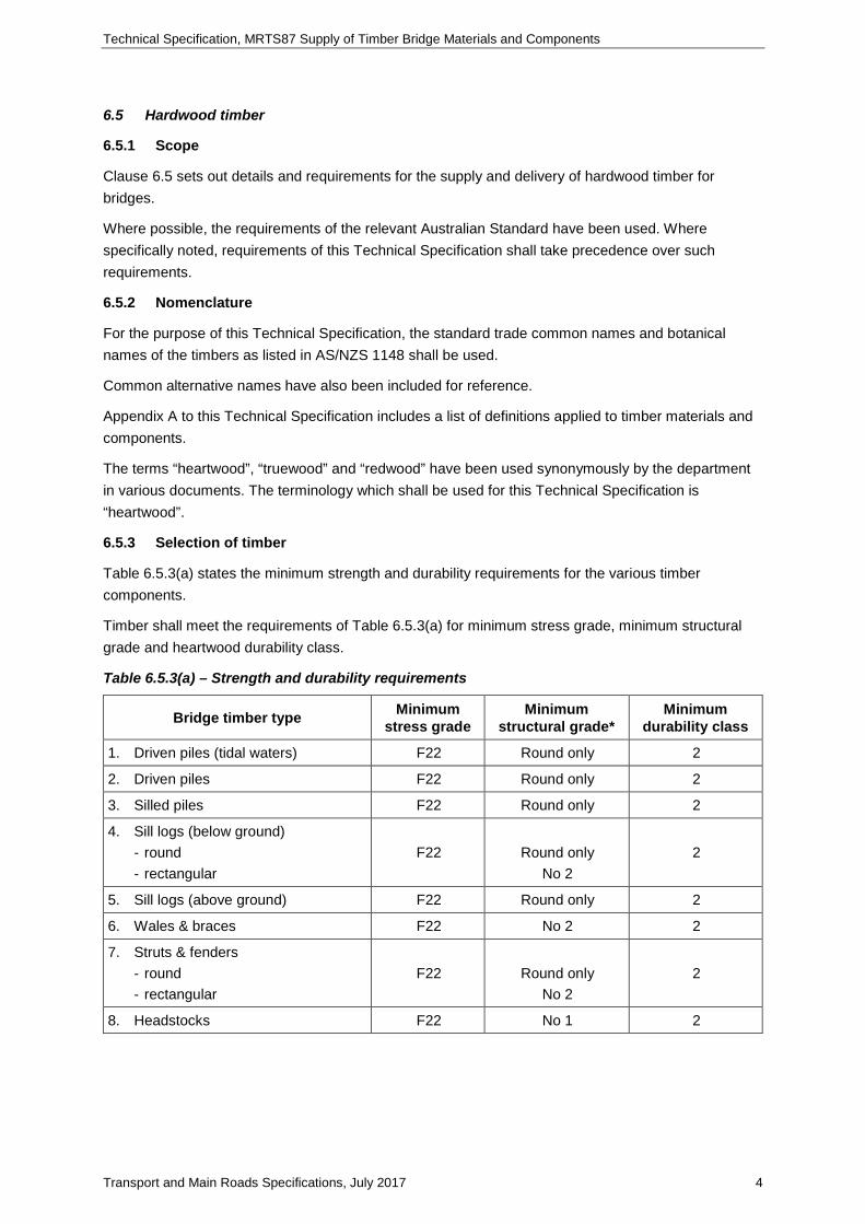
Table 6.5.3(a) states the minimum strength and durability requirements for the various timber components.
Timber shall meet the requirements of Table 6.5.3(a) for minimum stress grade, minimum structural grade and heartwood durability class.
Table 6.5.3(a) – Strength and durability requirements
Bridge timber type Minimum stress grade
Minimum structural grade*
Minimum durability class
1. Driven piles (tidal waters) F22 Round only 2
2. Driven piles F22 Round only 2
3. Silled piles F22 Round only 2
4. Sill logs (below ground) - round - rectangular
F22
Round only No 2
2
5. Sill logs (above ground) F22 Round only 2
6. Wales & braces F22 No 2 2
7. Struts & fenders - round - rectangular
F22
Round only No 2
2
8. Headstocks F22 No 1 2

Technical Specification, MRTS87 Supply of Timber Bridge Materials and Components
Transport and Main Roads Specifications, July 2017 5
Bridge timber type Minimum stress grade
Minimum structural grade*
Minimum durability class
9. Girders - round - octagonal
F27
F27 (F22**)
Round only
No 1 2
10. Corbels F22 2
11. Spiking planks F22 No 2 2
12. Deck planks (transverse) F22 No 2 2
13. Deck planks (longitudinal) F22 No 2 2
14. Distributor planks F17 No 2 2
15. Running planks F17 No 2 2
16. Kerbs F17 No 2 2
17. Ballast & cover boards F17 No 3 2
18. Backing boards F17 No 3 1
19. Handrails*** F17 No 2 2
* Refer to AS 2082 for sawn timber and AS 3818 for round timber.
** Minimum Stress Grade F22 may be used for sawn girders, provided the central third of the length is free of knots or other noticeable defects on the nominated tension faces. This effectively achieves the minimum stress grade required.
*** Note that standard timber handrails do not satisfy minimum containment standards. Before component repairs are programmed, consideration shall be given to replacement with a more appropriate barrier. Tables 6.5.3(b) and 6.5.3(c) are used to select suitable timber species that comply with these requirements.
Table 6.5.3(b) – Relationship between strength groups and stress grades for unseasoned timber
Strength group
Stress Grade
No. 1 Structural
No. 2 Structural
No. 3 Structural
Round timber (piles, girders, corbels, sills)
S1 F27 F22 F17 F34
S2 F22 F17 F14 F27
S3 F17 F14 F11 F22
Table 6.5.3(c) – Strength and durability classifications for various species
Common name Botanical name Strength group unseasoned
Heartwood durability class
Black Ironbox (Thozets Box)** E. raveretiana S2 1
Carbeen (Moreton Bay Ash) E. tessellaris (S1)* 2
Cooktown Ironwood (Ironwood) Erythrophleum laboucheri S1 1
Forest Red Gum (Blue Gum) E. tereticornis S3 2

Technical Specification, MRTS87 Supply of Timber Bridge Materials and Components
Transport and Main Roads Specifications, July 2017 6
Common name Botanical name Strength group unseasoned
Heartwood durability class
Gympie Messmate (Dead Finish) E. cloeziana S2 1
Grey Gum E. punctata S1 1
Hickory Ash (Grey Hickory) Flindersia ifflaiana S1 1
Ironbark – Grey E. paniculata S1 1
Ironbark – Narrow-leafed Red E. crebra S2 1
Ironbark – Broad-leafed Red E. siderophloia S1 1
Red Bloodwood Corymbia corymbosa S3 1
Spotted Gum Corymbia maculata S2 2
Tallowwood (Luster) E. microcorys S2 1
Turpentine Syncarpia laurifolia S3 1
White Mahogany (Yellow Stringbark) E. acmenoides S2 2
E. = eucalyptus
* provisional status
** Black Ironbox is a declared vulnerable timber species and requires EPA and Environment Australia approval before harvesting (Refer to Natural Conservation Act 1992 and Environment Protection and Biodiverstity Conservation Act 1999). For sawn timber, Table 6.5.3(b) shows the correspondence between required stress grade and the strength group and structural grade. For naturally round timber, Table 6.5.3(b) also shows the relationship between stress grade and strength group.
Appendix E to this Technical Specification provides a number of worked examples for timber selection.
Hardwood species other than those listed in Table 6.5.3(c) may be suitable for use as bridge timbers, subject to consultation with the Administrator. At least 14 days prior to supply to the Site, the Contractor shall provide to the Administrator a submission fully detailing the alternative materials. Milestone The submission shall include a report from the Department of Agriculture and Fisheries detailing properties which indicate suitability of the material for its intended purpose. Hardwood species submitted for approval shall have a minimum Strength Group (unseasoned) Classification of S3 and a Durability Classification of at least two. The minimum strength and durability requirements of Table 6.5.3(a) shall also be adhered to for particular components. Material shall not be delivered to the Site until expiration of the 14 day period. Hold Point 1
Notwithstanding the above, species which include Coastal Blackbutt and Mountain (Gum Top) Ironbark are not permitted to be used.
For full re-builds of decks or a span of girders, the supply of decking and girders in one species only is required.
Appendix B to this Technical Specification provides a summary of traditional approved timber species based on their source growing area and bridge usage.

Technical Specification, MRTS87 Supply of Timber Bridge Materials and Components
Transport and Main Roads Specifications, July 2017 7
6.5.4 Inspection
The Contractor shall arrange for all timber to be inspected by its nominated representative at the point of delivery or at the supplier’s mill before despatch. Identification marks shall be placed on the timbers which pass such inspection. Timber presented for use shall be placed a minimum of 300 mm above the ground and spaced in such a way that it can be rolled allowing a visual inspection at all sides. The Administrator shall be given at least five working days’ notice of the inspection to enable a representative of the Administrator to be present at the inspection. Milestone
The thickness of plywood decking shall be checked to confirm nominal ordered thickness, which shall generally be 130 or 155 mm however thickness up to 170 mm are permissable. The other nominal sheet dimension shall also be checked (nominally 1200 mm).
Departures may be permissible in some instances subject to the provisions of Clause 6.3 being met.
All sawn and round section timber shall be stamped with the species identification brand on a blaze (or metal tag) generally near the middle of the timber such that it shall be accessible during the life of the component. Hold Point 2 A checklist suitable for use in inspecting sawn timber girders is included in Appendix G.
6.5.5 Sawn timber
Sawn timber shall be cut square. The quality and dimensional tolerances of sawn timber shall comply with Section 2 of AS 2082 except that:
a) Headstock, transverse and longitudinal decking, spiking planks and bracing members may contain wane and want to the dimensions listed for untreated sapwood in Clause 6.5.7.4. In this case, any associated sapwood shall be preservative treated to the requirements of Clause 6.5.7. Decking, spiking plank and bracing shall also be free of boxed heart.
b) Unless otherwise ordered, headstock members shall be supplied free of heart. However, the Administrator may elect to allow heart material, to reduce the twisting and bowing resulting from the sawing process. In this case, the heart material shall be sound, without piping or significant separation and shall be located within the central third of the section, as shown in Appendix C. The member thickness shall also be increased to a minimum of 200 mm, and
c) For girders and corbels:
i. Tight knots up to 50 mm maximum diameter may be accepted provided they appear in one face only at any section. No more than one knot in every metre of length of the member shall be permitted.
ii. The requirement for limiting grain slope may be omitted.
iii. Tight gum veins or smears shall not be longer than 150 mm individually and not closer than one metre centres.
iv. Loose gum veins and pockets shall not extend through the member and appear on two faces.
v. Wane and want shall not exceed 25 mm x 25 mm on arrises.
vi. Lyctid susceptible sapwood may not exceed 10% of the cross sectional area.
vii. Bow shall not exceed 20 mm for six metre lengths and 30 mm for nine metre lengths.

Technical Specification, MRTS87 Supply of Timber Bridge Materials and Components
Transport and Main Roads Specifications, July 2017 8
viii. The thickness of decking and width and depth of a headstock member shall not be less than that specified in the Contract.
ix. Checks and Shakes - if not exceeding 10 mm in width for not more than two checks and / or shakes at a cut end and not exceeding 5 mm in width for the remainder (measured outside a 60 mm diameter at the heart).
x. End Splits (extending through from face-to-face) - if not exceeding 5 mm in width (measured outside a 60 mm diameter at the heart) and not exceeding 300 mm in depth. End splits of any size occurring on or about the same plane at both cut ends shall not be permitted, and
xi. Double Heart – (Heart and Limb) - provided that the hearts at the end of the member are located in the inner and / or middle zones and are not more than 250 mm apart in the cross-section.
Where sawn girders and corbels are supplied, they shall be sawn to an octagonal template. Each girder or corbel shall have at least four sawn faces and, where sapwood is present, the member shall be preservative treated to the requirements of Clause 6.5.7.
Where sawn girders and corbels are supplied, the cut ends shall have approved metal nail plates attached, or anti-splitting bolts placed through the member, at the time of assembly in a job (i.e. after trimming to length). In the case of headstocks, large rectangular plates shall be applied to the ends.
Girders and corbels may be supplied with up to a 50 mm diameter central pipe, but this shall be plugged before use in a job, as detailed in the Timber Bridge Maintenance Manual.
All timber decking shall be backsawn in order to minimise shrinkage distortions.
Refer to Appendix C for minimum dimensions required for various components.
6.5.6 Round timber
6.5.6.1 Girders and corbels
The diameter of round timbers before dressing shall be as stated in the Contract and the minimum diameter at the small end shall be such that these dimensions are fulfilled. As a guide, Appendix C provides minimum diameters for girders for various spans and bridge design classes.
Round timbers shall taper naturally and uniformly at not more than 8 mm of diameter per metre of length. All round timber shall be stripped of bark immediately after felling. The quality and dimensional tolerance of round timbers shall comply with AS 3818.
Orders for round timber shall specify that approved metal nail plates be attached to the ends immediately after cutting in order to reduce the amount and extent of end splitting.
Where desapped girders and corbels are supplied, the resultant diameter shall satisfy the minimum specified on the order.
If girders and corbels are supplied with sapwood, the sapwood may be included to satisfy the minimum diameter requirements. The girders and corbels shall be treated with preservative to the requirements of Clause 6.5.7.
Girders and corbels may be supplied with up to a 50 mm diameter central pipe, but this shall be plugged before use in a job, as shown in the Timber Bridge Maintenance Manual.

Technical Specification, MRTS87 Supply of Timber Bridge Materials and Components
Transport and Main Roads Specifications, July 2017 9
6.5.6.2 Piles
Piles shall have a minimum diameter as stated in the Contract at a distance of 500 mm from the butt, and a minimum diameter of 300 mm at the toe, unless otherwise ordered.
Pile quality and dimensional tolerances shall comply with AS 3818.3, except Clause 1.7.4 shall be varied such that piles shall be approximately circular in cross-section to within 500 mm of the butt.
All piling shall be debarked but shall have the sapwood remaining. The piles shall be treated in accordance with the requirements of Clause 6.5.7.
6.5.7 Preservative treatment
6.5.7.1 General
Preservative treatments shall be in accordance with the requirements of AS 1604.1.
Where preservative treatment of components is required, these shall be stamped with the compliance data specified by AS 1604.1. This may take the form of metal tags attached to the side of the member where nailing plates have been attached to the ends. In addition, a certified compliance certificate shall be provided to the Administrator. Hold Point 3
The measurement of sapwood thickness, for the purpose of determining preservative treatment requirements, is to exclude wane, when wane is present.
6.5.7.2 End coating
An approved wax emulsion type or Denso Primer end sealing compound shall be applied to the end region of girders and corbels to reduce the rate of drying of the timber and to control shrinkage and end splits. This shall occur as soon as practicable, but less than 12 hours after the timbers have been cut:
a) For timbers which are not to be preservative treated, the sealer shall be applied to the ends and also for a length of 600 mm from the ends of the timbers, and
b) For timbers which are to be preservative treated, the sealer shall be applied to the ends of the timbers only. As soon as practicable after preservative treatment, the sealer shall be reapplied to the ends and also for a length of 600 mm from the ends of the timbers.
For all timbers held in storage, the sealer shall be reapplied to the ends and also for a length of 600 mm from the ends of the timber at an interval no greater than three months.
6.5.7.3 Sapwood on round girders and corbels
If round girders and corbels are supplied in an unsapped form the sapwood shall be treated to Hazard Level 5. Treatment is required in order to make the sapwood durable and also resistant to lyctid borer. All treated girders and corbels shall be branded and a certificate of treatment supplied with each girder and corbel.
6.5.7.4 Sapwood on sawn timber
All sapwood shall be treated to Hazard Level 5, except where:
a) sapwood does not exceed 12 mm x 12 mm on one arris up to full length of headstock members, or 25 mm x 25 mm on all arrises of an octagonal girder or corbel member
b) sapwood does not exceed 20 mm x 20 mm on one arris or 10 mm x 10 mm on two arrises up to full length of bracing members and spiking planks, or
Technical Specification, MRTS87 Supply of Timber Bridge Materials and Components
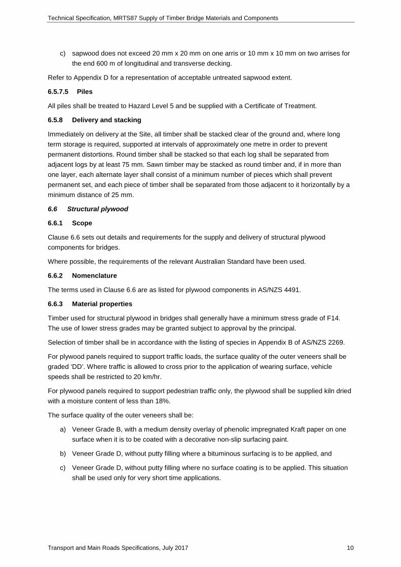
Transport and Main Roads Specifications, July 2017 10
c) sapwood does not exceed 20 mm x 20 mm on one arris or 10 mm x 10 mm on two arrises for the end 600 m of longitudinal and transverse decking.
Refer to Appendix D for a representation of acceptable untreated sapwood extent.
6.5.7.5 Piles
All piles shall be treated to Hazard Level 5 and be supplied with a Certificate of Treatment.
6.5.8 Delivery and stacking
Immediately on delivery at the Site, all timber shall be stacked clear of the ground and, where long term storage is required, supported at intervals of approximately one metre in order to prevent permanent distortions. Round timber shall be stacked so that each log shall be separated from adjacent logs by at least 75 mm. Sawn timber may be stacked as round timber and, if in more than one layer, each alternate layer shall consist of a minimum number of pieces which shall prevent permanent set, and each piece of timber shall be separated from those adjacent to it horizontally by a minimum distance of 25 mm.
6.6 Structural plywood
6.6.1 Scope
Clause 6.6 sets out details and requirements for the supply and delivery of structural plywood components for bridges.
Where possible, the requirements of the relevant Australian Standard have been used.
6.6.2 Nomenclature
The terms used in Clause 6.6 are as listed for plywood components in AS/NZS 4491.
6.6.3 Material properties
Timber used for structural plywood in bridges shall generally have a minimum stress grade of F14. The use of lower stress grades may be granted subject to approval by the principal.
Selection of timber shall be in accordance with the listing of species in Appendix B of AS/NZS 2269.
For plywood panels required to support traffic loads, the surface quality of the outer veneers shall be graded ‘DD’. Where traffic is allowed to cross prior to the application of wearing surface, vehicle speeds shall be restricted to 20 km/hr.
For plywood panels required to support pedestrian traffic only, the plywood shall be supplied kiln dried with a moisture content of less than 18%.
The surface quality of the outer veneers shall be:
a) Veneer Grade B, with a medium density overlay of phenolic impregnated Kraft paper on one surface when it is to be coated with a decorative non-slip surfacing paint.
b) Veneer Grade D, without putty filling where a bituminous surfacing is to be applied, and
c) Veneer Grade D, without putty filling where no surface coating is to be applied. This situation shall be used only for very short time applications.
Technical Specification, MRTS87 Supply of Timber Bridge Materials and Components
Transport and Main Roads Specifications, July 2017 11
6.6.4 Component design
Where an alternative deck utilising plywood decking is proposed, at least 28 days prior to ordering plywood, the Contractor shall provide to the Administrator a submission fully detailing the alternative materials and design. Milestone Material shall not be delivered to the Site until expiration of the 28 day period. Hold Point 4
6.6.5 Component fabrication
The structure of plywood used in bridges may be:
a) Thin panels (i.e. less than 50 mm thickness) used for pedestrian walkways which are formed as conventional plywood sheets, and
b) Thick panels (i.e. greater than 50 mm thickness) used for bridge decks or kerbs. These are produced by cold-bonding together a number of formed 25 mm or thicker plywood substrates to give the specified dimensions.
Both thin plywood sheets and substrates shall comply with the manufacturing requirements of Section 3 of AS/NZS 2269.
Bonding between the layers of ply or individual veneers shall be Type A bond in all cases.
Where thick plywood sheets are formed, any end joints in outer substrates shall be formed as scarf joints to the requirements of Section 3.2 of AS/NZS 2269.
However, end joints in internal substrates may be formed as butt joints, provided these butt joints are staggered by at least 300 mm.
Section 3.4.1 of AS/NZS 2269 requires ply sheets to be free of ferrous materials, such as clips and staples. However, metal self-tapping screws may be used for the assembly of ply substrates to form thick sheets. These are required to provide pressure to the cold-bonding glue lines. In addition, staples may be used in the outer sheets during the scarfing process.
6.6.6 Preservative treatment
All plywood components shall be preservative treated to the requirements of AS 1604.3.
Plywood panels above ground shall be treated to Hazard Level 3 while panels in contact with the ground shall be treated to Hazard Level 4. All plywood panel surfaces shall be free of surface deposits.
Plywood panels shall be stamped with the compliance data specified by AS 1604. In addition, a certified compliance certificate shall be supplied to the Principal. Hold Point 5
6.6.7 Inspection
Unless otherwise arranged, all plywood components shall be inspected by the Contractor’s nominated representative on delivery to the Site. The Administrator shall be given at least five working days’ notice of the inspection to enable a representative of the Administrator to be present at the inspection. Milestone
In checking thickness of plywood panels, allowance shall also be made for swelling of structural plywood during the preservative treatment process. This may be up to 10% of thickness immediately after treatment, but gradually reducing with time.

Technical Specification, MRTS87 Supply of Timber Bridge Materials and Components
Transport and Main Roads Specifications, July 2017 12
For plywood decking, the location of transverse butt joints in internal substrates shall be checked to confirm staggering of these joints as required by Clause 6.6.5.
Any delamination visible in the ends of sheets which indicates failure in bonding of substrates or veneers shall be recorded, and the sheets rejected.
6.6.8 Delivery and stacking
Immediately after delivery to the Site, structural plywood panels shall be carefully stored to keep the material in good condition.
Recommended procedures are:
a) The storage area shall be protected from sun, rain and wind that would otherwise bring about rapid changes in temperature and humidity.
b) Support for the sheets shall be provided at both ends and middle to avoid distortion. The maximum spacing of supports shall be 1500 mm.
c) The stack shall be kept dry and clear of ground contact, and be placed so that it shall not be exposed to mechanical damage.
d) The sheets shall be stacked on their flat, NOT on edge, and
e) To avoid staining, fading and surface checking, the sheets shall not be exposed to the weather while awaiting installation.
6.7 Precast prestressed concrete bridge decking
6.7.1 Scope
Clause 6.7 sets out the requirements for the supply and delivery of precast prestressed concrete (PSC) deck planks used as alternative decking on timber bridges.
These are proprietary products and attention is drawn to the requirements of Clause 6.3 of this specification.
6.7.2 Component design
Where an alternative deck utilising PSC bridge decking is proposed, at least 28 days prior to ordering PSC components, the Contractor shall provide to the Administrator a submission fully detailing the alternative materials and design. Milestone Material shall not be delivered to the Site until expiration of the 28 day period. Hold Point 6
6.7.3 Component supply and storage
Supply, transport and site storage of precast prestressed concrete bridge decking shall be carried out in accordance with the requirements of Technical Specifications:
a) MRTS70 Concrete, and
b) MRTS72 Manufacture of Precast Concrete Elements
c) MRTS73 Manufacture of Prestressed Concrete Members and Stressing Units.
The supply of steel distributor members shall be in accordance with the requirements of MRTS78 Fabrication of Structural Steelwork.
Unless otherwise arranged, all components shall be inspected on delivery to the Site.

Technical Specification, MRTS87 Supply of Timber Bridge Materials and Components
Transport and Main Roads Specifications, July 2017 13
6.8 Steel bridge decking
6.8.1 Scope
Clause 6.8 sets out the requirements for the supply and delivery of steel bridge decking as an alternative decking on timber bridges.
This is a proprietary product and attention is drawn to the requirements of Clause 6.3 of this Technical Specification.
6.8.2 Component design
Where an alternative deck utilising steel bridge decking is proposed, at least 28 days prior to ordering materials, the Contractor shall provide to the Administrator a submission fully detailing the alternative materials and design. Milestone Material shall not be delivered to the Site until expiration of the 28 day period. Hold Point 7
Unless specific approval has been granted by the Principal, only reinforced concrete shall be used for the infill material in steel decks.
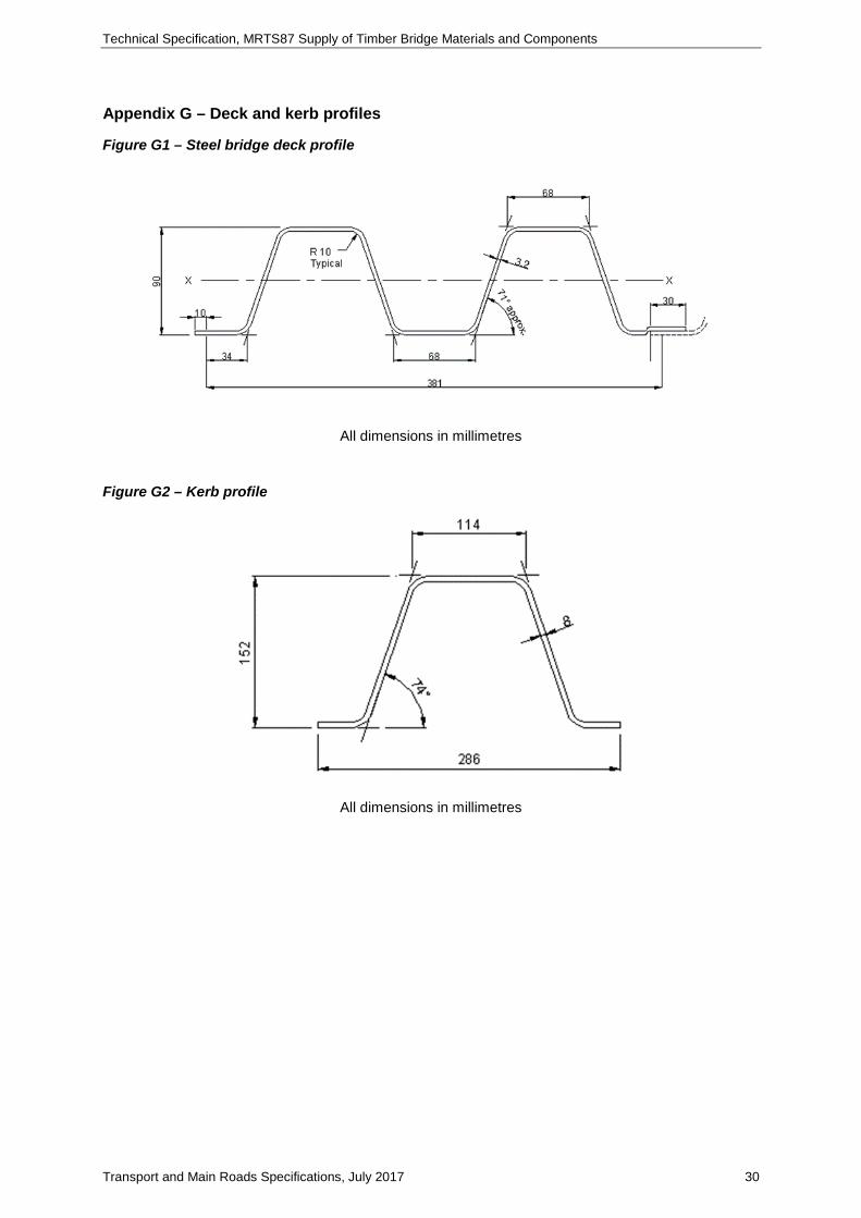
Unless otherwise scheduled, steel road bridge decking shall conform to the following requirements:
a) roll-formed from 3.2 mm thick steel plate
b) steel grade shall be Grade 300 to the requirements of AS 1397, and
c) depth of decking shall be 90 mm (refer to Appendix G for the approved corrugation profile for decking and kerb members).
6.8.3 Component installation
Where steel decking is proposed it is a requirement that it be installed in a transverse direction and this must be allowed for in the engineering design.
6.8.4 Component supply and storage
Steel bridge decking shall be hot dip galvanized with a heavy duty 600 gm/m² coating mass to the requirements of AS/NZS 4680.
Unless otherwise arranged, steel bridge decking shall be inspected by the Contractor’s nominated representative on delivery to the Site. The Administrator shall be given at least five working days’ notice of the inspection to enable a representative of the Administrator to be present at the inspection. Milestone
The stacks of steel decking shall be supported clear of the ground on timber blocks.
6.9 Fibre reinforced polymer composite girders
Clause 6.9 sets out the requirements for the supply, delivery and installation of fibre reinforced polymer composite girders. These components may be used as an alternative to conventional timber girders for particular applications which include the following:
a) replacement of timber girders in an existing timber bridge, or
b) in the construction of a superstructure in an existing timber bridge.
Fibre reinforced polymer girders shall be manufactured in accordance with MRTS59. Installation shall be in accordance with MRTS60. This is a proprietary product and attention is drawn to Clause 6.3 of this Technical Specification.
Technical Specification, MRTS87 Supply of Timber Bridge Materials and Components
Transport and Main Roads Specifications, July 2017 14
Appendix A – List of definitions
Extract from AS 3818.1.
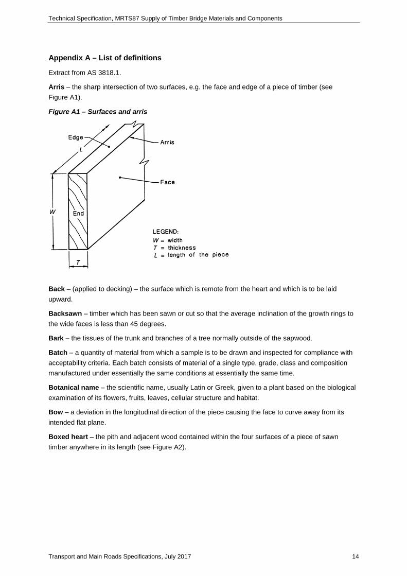
Arris – the sharp intersection of two surfaces, e.g. the face and edge of a piece of timber (see Figure A1).
Figure A1 – Surfaces and arris
Back – (applied to decking) – the surface which is remote from the heart and which is to be laid upward.
Backsawn – timber which has been sawn or cut so that the average inclination of the growth rings to the wide faces is less than 45 degrees.
Bark – the tissues of the trunk and branches of a tree normally outside of the sapwood.
Batch – a quantity of material from which a sample is to be drawn and inspected for compliance with acceptability criteria. Each batch consists of material of a single type, grade, class and composition manufactured under essentially the same conditions at essentially the same time.
Botanical name – the scientific name, usually Latin or Greek, given to a plant based on the biological examination of its flowers, fruits, leaves, cellular structure and habitat.
Bow – a deviation in the longitudinal direction of the piece causing the face to curve away from its intended flat plane.
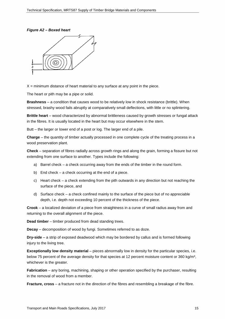
Boxed heart – the pith and adjacent wood contained within the four surfaces of a piece of sawn timber anywhere in its length (see Figure A2).
Technical Specification, MRTS87 Supply of Timber Bridge Materials and Components
Transport and Main Roads Specifications, July 2017 15
Figure A2 – Boxed heart
X = minimum distance of heart material to any surface at any point in the piece.
The heart or pith may be a pipe or solid.
Brashness – a condition that causes wood to be relatively low in shock resistance (brittle). When stressed, brashy wood fails abruptly at comparatively small deflections, with little or no splintering.
Brittle heart – wood characterized by abnormal brittleness caused by growth stresses or fungal attack in the fibres. It is usually located in the heart but may occur elsewhere in the stem.
Butt – the larger or lower end of a post or log. The larger end of a pile.
Charge – the quantity of timber actually processed in one complete cycle of the treating process in a wood preservation plant.
Check – separation of fibres radially across growth rings and along the grain, forming a fissure but not extending from one surface to another. Types include the following:
a) Barrel check – a check occurring away from the ends of the timber in the round form.
b) End check – a check occurring at the end of a piece.
c) Heart check – a check extending from the pith outwards in any direction but not reaching the surface of the piece, and
d) Surface check – a check confined mainly to the surface of the piece but of no appreciable depth, i.e. depth not exceeding 10 percent of the thickness of the piece.
Crook – a localized deviation of a piece from straightness in a curve of small radius away from and returning to the overall alignment of the piece.
Dead timber – timber produced from dead standing trees.
Decay – decomposition of wood by fungi. Sometimes referred to as doze.
Dry-side – a strip of exposed deadwood which may be bordered by callus and is formed following injury to the living tree.
Exceptionally low density material – pieces abnormally low in density for the particular species, i.e. below 75 percent of the average density for that species at 12 percent moisture content or 360 kg/m³, whichever is the greater.
Fabrication – any boring, machining, shaping or other operation specified by the purchaser, resulting in the removal of wood from a member.
Fracture, cross – a fracture not in the direction of the fibres and resembling a breakage of the fibre.
Technical Specification, MRTS87 Supply of Timber Bridge Materials and Components
Transport and Main Roads Specifications, July 2017 16
Grade – an established quality or use classification of timber or timber products.
Grain – the general direction of the fibres or wood elements relative to the main axis of the piece: cross, sloping, diagonal, interlocked, spiral, straight. Sloping grain (also referred to as cross grain) is grain that is not parallel to the edges or surface of a girder or corbel.
Green – unseasoned, wet, with free water present in the cell cavities.
Gum pocket – a cavity which contains or has contained gum or kino.
Gum ring – a deposition of gum or kino concentric with the growth rings, extending round a considerable proportion of the circumference of a ring.
Gum vein – a ribbon of gum or kino between growth rings which may be bridged radially at short intervals by wood tissue.
Gum vein, loose – a gum vein associated with extensive discontinuity of wood tissue.
Gum vein, tight – a gum vein which is bridged radially at close intervals with woody tissue and not associated with extensive discontinuity of wood tissue.
Hardwood – a wood from trees classified botanically as Angiosperms. Most hardwood trees are broad-leaved, and the wood is pored. The term does not denote the relative hardness of the wood, though sometimes used in this sense.
Heart – the portion of a log that includes the pith, if applicable, and the associated wood of reduced strength.
Heart, faulty – heart that is not tight and sound.
Heartwood – wood in which the living tree had ceased to contain living cells and in which the reserve materials (e.g. starch) had been removed or changed into more durable substances.
Hole – a hole extending partially or entirely through the piece and attributable to any cause as follows:
a) Borer hole – a small hole in timber caused by the larval or adult stage of a wood boring insect, e.g. Lyctic, Anobid, Bostrychid, Platypodid or Lymexylid.
b) Grub hole – a hole or excavation usually larger than a borer hole, made by the larval or adult stage of an insect, e.g. Cerambycid, Buprestid or Lepidoptera.
c) Pinhole – usually stained, made by a pinhole borer, i.e. Platypodid or Lymexylid.
d) Plugged hole – a hole filled by inserting a matching piece of wood, and
e) Termite hole – see Termite Gallery.
Kink – an abrupt offset occurring in a length of log. Applied to piles, means a deviation from straightness whereby one straight section of a pile is offset from another straight section.
Knot – a section of a branch which is embedded in the wood of a tree trunk or of a larger branch. Knots are defined with respect to their position on a cross-section of a piece or by their appearance on a surface:
a) defective knot – a loose or unsound knot
b) loose knot – a knot which is not held firmly in place by growth and which cannot be relied upon to remain in place in the piece

Technical Specification, MRTS87 Supply of Timber Bridge Materials and Components
Transport and Main Roads Specifications, July 2017 17
c) sound knot – a knot solid across its face, as hard as the surrounding tissue and free from decay, and
d) unsound knot – a knot more or less decayed and softer than the surrounding tissue; not solid across the face; checked or split.
Pile – a round timber member which is sunk into the ground to support axial or lateral loads.
Pipe – a longitudinal cavity along the growth centre of round timber.
Plug sample – a cylindrical sample taken by coring to at least the full depth of any sapwood.
Quartersawn – timber which has been sawn or cut so that the average inclination of the growth rings to the wide faces is more than 45 degrees.
Refractory – resistant to penetration by wood preservatives.
Rot, primary – heart rot or a pocket of rot occurring in the living tree before felling.
Sapwood – the outer layers of the wood of a tree which, when the tree was living, contained tissue in which water and food materials were conveyed and stored; generally lighter in colour than the heartwood.
Seasoned timber – timber brought to a state of equilibrium moisture content.
Shake – a partial or complete dislocation, breakage or longitudinal separation of wood fibres due to causes other than drying and usually originating either in the standing tree or in the log during felling or conversion as in the following:
a) heart shake – a shake extending from the pith of a tree
b) ring shake – a shake following a growth ring. Also referred to as a shell shake or cup shake and the timber may be described as 'shelly', and
c) star shake – a number of adjoining heart shakes in the form of a star.
Shell-off – missing material resulting from a ring shake.
Sole plate – a horizontal timber pad normally of square surface dimension laid in or on the ground to support a post or prop in order to distribute the load.
Spall – a localized separation of fibres near the surface, usually resulting from an axe cut.
Split – a longitudinal separation of wood fibres which extends through a piece from one surface to another in sawn timber or through round timber.
Split, end – a split at the end of a log or piece.
Spiral grain – where the wood fibres take a helical course about the bole of the tree, instead of the more common vertical course. The spiral grain may extend right handed or left handed around the trunk.
Spring – a deviation in the longitudinal direction of the piece, causing the edge to curve away from its intended flat plane.
Sweep – the deviation of the piece from straightness, in a curve of large radius, which occurs in:
a) one direction in one plane (single sweep), or
b) two directions in any plane (multiple sweep).

Technical Specification, MRTS87 Supply of Timber Bridge Materials and Components
Transport and Main Roads Specifications, July 2017 18
Termite gallery – an irregularly shaped passage or burrow excavated by termites in the bark or wood. An enclosed termite gallery is one which is not completely open to visual inspection throughout its entire length.
Thickness (T) – the smaller dimension of the cross-section of a piece of timber (see Figure A1).
Top – small end of a post.
Toe – small end of a pile.
Twist – a spiral distortion along the length of a piece of timber.
Wane – the presence of the original underbark surface with or without bark, on any face or edge of a piece of timber.
Want – the absence of wood, other than wane, from the corner or surface of a piece of timber.
Warp – a distortion which is generally regular, part or all of the surface having become curved.
Width (W) – the larger dimension in the cross-section of a piece (see Figure A1).
Zone, penetrated – that part of the member required to be penetrated with preservative.
Strength group – group representing the inherent strength of a timber species. There are seven strength groups for unseasoned timber (S1 to S7) and eight for seasoned timber (SD1 to SD8).
Stress grade – the classification of a piece of timber for structural purposes, to the relevant Australian Standard, to indicate its characteristic structural properties and stiffness.

Technical Specification, MRTS87 Supply of Timber Bridge Materials and Components
Transport and Main Roads Specifications, July 2017 19
Appendix B – Timber species growing areas

Technical Specification, MRTS87 Supply of Timber Bridge Materials and Components
Transport and Main Roads Specifications, July 2017 20
APP
RO
VED
GR
OW
ING
AR
EAS
WHITE MAHOGANY
5*
5*
5*
5*
ALL
1, 5
*
5*
ALL
4**,
5*
ALL
*
=
N
orth
of 1
9º o
nly
††
=
free
of h
eart
=
han
drai
ls o
nly
**
=
N
orth
of 2
2½º o
nly
=
abo
ve th
e ra
nge
only
†
=
Nor
th o
f Tow
nsvi
lle b
ut 2
5mm
ext
ra d
iam
eter
=
w
ales
& b
race
s on
ly
TURPERTINE
4†,5
†
1,2,
3,4*
*,5*
TALLOWWOOD 1,
2,3 1,
2,3 2
SPOTTED GUM A
LL
3 ALL
1,2,
3,
4
RED BLOODWOOD 5*
1,2,
3,4
5*
1,2,
3,4
5*
5*
4
5*
ALL
IRONBARK BROAD-LEAF RED 1 1 1 1 1 1 1 1 1 1
IRONBARK NARROW-LEAF RED A
LL
ALL
ALL
ALL
ALL
ALL
ALL
ALL
ALL
ALL
IRONBARK – GREY A
LL
ALL
ALL
ALL
ALL
ALL
ALL
ALL
ALL
ALL
HICKORY ASH 5*
5*
5*
5*
5*
5*
5*
5*
GREY GUM 1, 2 1, 2 1, 2 1, 2 1, 2
GYMPIE MESSMATE A
LL
ALL
5 ALL
ALL
ALL
FOREST RED GUM
ALL
1,2,
3,
4
5
1,2,
3,4,
5
1,2,
3,
4,5*
1,2,
3
COOKTOWN IRONWOOD 5*
CARBEEN
4**
4**
4**
BLACK IRONBOX
3,4*
*
4**
3 3 3
DR
IVEN
PIL
ES
SILL
ED P
ILES
SILL
LO
GS
BEL
OW
GR
OU
ND
SILL
LO
GS
AB
OVE
GR
OU
ND
WA
LES
BR
AC
ES
HA
ND
RA
ILS
HEA
DST
OC
KS
GIR
DER
S C
OR
BEL
S K
ERB
S
SPIK
ING
PLA
NK
S
DEC
K P
LAN
KS
BA
LLA
ST &
CO
VER
B
OA
RD
S

Technical Specification, MRTS87 Supply of Timber Bridge Materials and Components
Transport and Main Roads Specifications, July 2017 21
Appendix C – Standard headstock dimensions*
Figure C1 – Headstock with heart inclusion
Standard decking thickness*
Figure C2 – Standard decking thickness*
* These dimensions correspond to those shown on the original bridge drawings.
Actual supplied dimensions shall correspond to standardized commercial cutting sizes and shall be the nearest sizes available. A maximum reduction of 5 mm on original drawing dimensions is acceptable.

Technical Specification, MRTS87 Supply of Timber Bridge Materials and Components
Transport and Main Roads Specifications, July 2017 22
Standard girder diameters for various spans
‘A’ class loading:
Span m
Original deck width
m No. of girders
Girder diameter inches (mm)
Outer Inner
4.6 – 4.9 3.66 4
12 (304) 14 (355) 5.5 5
5.2 – 5.8 3.66 4
13 (330) 15 (381) 5.5 5
6.1 – 6.7 3.66 4
14 (355) 16 (406) 5.5 5
7.0 3.66 4
15 (381) 17 (431) 5.5 5
7.3 – 8.2 3.66 4
16 (406) 18 (457) 5.5 5
8.5 – 9.1
3.66 4 17 (431) 19 (482)
5.5 5
6.1 6 16 (406) 18 (457)
10.7 3.66 4 19 (482) 21 (533) ‘B’ class loading:
Span m
Original deck width
m No. of girders
Girder diameter inches (mm)
Outer Inner
3.0 – 4.9 3.66 4
10 (254) 12 (304) 5.5 5
5.2 – 5.8 3.66 4
11 (279) 13 (330) 5.5 5
6.1 – 6.7 3.66 4
12 (304) 14 (355) 5.5 5
7.0 – 7.6 3.66 4
13 (330) 15 (381) 5.5 5
7.9 – 8.5 3.66 4
14 (355) 16 (406) 5.5 5
8.8 – 9.1 3.66 4
15 (381) 17 (431) 5.5 5
10.7 3.66 4 16 (406) 18 (457)

Technical Specification, MRTS87 Supply of Timber Bridge Materials and Components
Transport and Main Roads Specifications, July 2017 23
Appendix D – Acceptable untreated sapwood
Figure D1 – Headstocks
Figure D2 – Bracing and spiking planks
Figure D3 – Decking

Technical Specification, MRTS87 Supply of Timber Bridge Materials and Components
Transport and Main Roads Specifications, July 2017 24
Appendix E(A) – Species selection flowchart
Figure E(A)1 – Species selection flowchart

Technical Specification, MRTS87 Supply of Timber Bridge Materials and Components
Transport and Main Roads Specifications, July 2017 25
Appendix E(B) – Worked examples – timber selection
Deck Planks
Step 1 From Table 6.5.3(a) of MRTS87, Item 12, decking is required to have a stress grade of at least F22, a structural grade of at least No. 2, and a durability rating of at least Class 2.
Step 2 From Table 6.5.3(b) of MRTS87, in the column for structural Grade 2, moving down as far as F22 and left from this point, leads to a minimum strength group of S1.
Step 3 From Table 6.5.3(c) of MRTS87, choose any timber which has a strength group of S1, combined with durability rating of Class 2 or better.
Suitable timbers are: Grey Ironbark, Broadleafed Red Ironbark, Grey Gum, Cooktown Ironwood, Carbeen, Hickory Ash.
Alternative Selection – if a higher timber structural grade then the specified minimum (i.e. No. 1) is selected from Table 4, timber with a lower strength group of S2 may be used.
Girders – Round
Step 1 From Table 6.5.3(a) of MRTS87, Item 9, obtain the minimum stress grade of F27 and the durability class requirement of Class 2. Because these are round timbers, the structural grading does not apply.
Step 2 From Table 6.5.3(b) of MRTS87, in the right hand column for round timber and moving down to the level for F27 gives a strength group requirement of at least S2.
Suitable timbers are: Grey Ironbark, Broad-leafed Red Ironbark, Grey Gum, Cooktown Ironwood, Carbeen, Black Ironbox, Gympie Messmate, Narrow-leafed Red Ironbark, Spotted Gum, Tallowood, White Mahogany, Hickory Ash.
Note that some of the above species are not included in the list shown in Appendix B which summarises the traditionally accepted timber species for various bridge components. The department has generally adhered to the list shown in Appendix B for timber selection over the past 90 years.
For main structural components such as decking, girders, headstocks and piles, Regions may elect to accept only those proven species shown in Appendix B. In such cases, the order for timber supplies shall be so annotated. However, any timber supplied for bridgeworks shall meet the minimum requirements specified in Tables 6.5.3(a) to 6.5.3(c) of MRTS87.

Technical Specification, MRTS87 Supply of Timber Bridge Materials and Components
Transport and Main Roads Specifications, July 2017 26
Appendix F – Octagonal sawn girders
Checklist
Timber supplier ...........................................................................................................................................
Inspection location ......................................................................................................................................
Inspector .....................................................................................................................................................
Date ............................................................................................................................................................
Girder identification .....................................................................................................................................
Order details ...............................................................................................................................................
Details
Yes No
• Sawn width (Satisfied tolerance ± 3 mm)
? ......................... ......................................reject
• Length (Acceptable - ∋ order length)
? ......................... ......................................reject (with consideration)
• Pipe size (Acceptable 50 mm diameter)
? ......................... ......................................reject
• Sawn to octagonal template
? ......................... ......................................reject
Supply species .................................................... Strength group
S1 S2
Quality tolerance (See over)
Yes No
• For Strength Group S1, satisfies Technical Specification MRTS87 requirements
? ......................... ...................................reject (or treat as S2)
• For Strength Group S2, satisfies Technical Standard MRTS87 requirements and free of knots or noticeable defects on middle third of length on nominated tension faces
? ......................... ..................................... reject
• Species identification brand in place
? ......................... ....................................... add

Technical Specification, MRTS87 Supply of Timber Bridge Materials and Components
Transport and Main Roads Specifications, July 2017 27
Preservative treatment
Yes No
• Sapwood > 25 x 25 mm on arris or policy of treating all sawn girders
? ............ arrange treatment ..............................................
• Post-treatment compliance stamp
? ......................... ................................. arrange
• Post-treatment compliance certificate
? ......................... ....................................obtain
GIRDER APPROVED .............................................................
• Inspection identification mark added -
• Preservative treatment arranged -
• Preservative treatment completed -
GIRDER REJECTED .............................................................
Reason or comment: ...........................................................................................................................
..............................................................................................................................................................
..............................................................................................................................................................

Technical Specification, MRTS87 Supply of Timber Bridge Materials and Components
Transport and Main Roads Specifications, July 2017 28
Allowable defects – Hardwood sawn girders
Using requirements of MRTS87 (AS 2082 Structural Grade 1 as modified)
Type of characteristic MRTS87 requirements Sketch Pass Fail
Tight knots* Up to 50 mm maximum diameter, provided in one face only at any section
Borer holes (not associated with decay): • diameter up to and
including 3 mm • diameter over 3 mm or
where separated by less than 2 x diameter
• Not exceeding 12 holes per 100 x 100 mm
• As for knots
Termite galleries
Enclosed galleries not permitted. If on the surface they shall be minor
Heart and heart shakes Permitted if located within middle third of section only
Tight gum veins (or smears)*
Not exceeding 150 mm individual length and not closer than one metre centres Not one surface to another
Loose gum veins, ring shakes and included bark Not permitted
Gum pockets, latex pockets, resin pockets; overgrowth of injury: * One surface to another and intersecting an end. Otherwise: • individual length not
exceeding • individual width
(measure radially) • one surface only: • one surface to another:
As for end splits • lesser of 3W or 300 mm • not exceeding 12 mm or ¼
of the surface on which it occurs
• not permitted
End splits, aggregate length Not exceeding W or 100 mm
External checks Width not exceeding 3 mm Individual length not exceeding L/4

Technical Specification, MRTS87 Supply of Timber Bridge Materials and Components
Transport and Main Roads Specifications, July 2017 29
Type of characteristic MRTS87 requirements Sketch Pass Fail
Primary rot
Depth not exceeding 3 mm Aggregate area in any 2 m of length not exceeding 150 x 100 mm
Want and wane Not exceeding 25 x 25 mm on arris
Lyctid susceptible sapwood
May not exceed 10% of area of section
Hit and miss, exceeding the limits for want and wane
Depth not exceeding 3 mm Individual length not exceeding 600 mm
Bow Maximum of: • 20 mm for 6 m length • 30 mm for 9 m length
* For S2 timber and these defects, none in middle third of length on nominated lower faces.
Technical Specification, MRTS87 Supply of Timber Bridge Materials and Components
Transport and Main Roads Specifications, July 2017 30
Appendix G – Deck and kerb profiles
Figure G1 – Steel bridge deck profile
All dimensions in millimetres
Figure G2 – Kerb profile
All dimensions in millimetres
