transport for london surface transport · transport for london surface transport management systems...
TRANSCRIPT
Transport for London
Surface Transport
Management Systems Document – Technical Specification
Traffic Directorate
Design Standards for Signal Schemes in London
Document reference: SQA-0064 issue: 3
Design Standards for Signal Schemes in London
SQA-0064 issue 3 Page 1 of 83
Intentionally left blank
Design Standards for Signal Schemes in London
SQA-0064 issue 3 Page 1 of 83
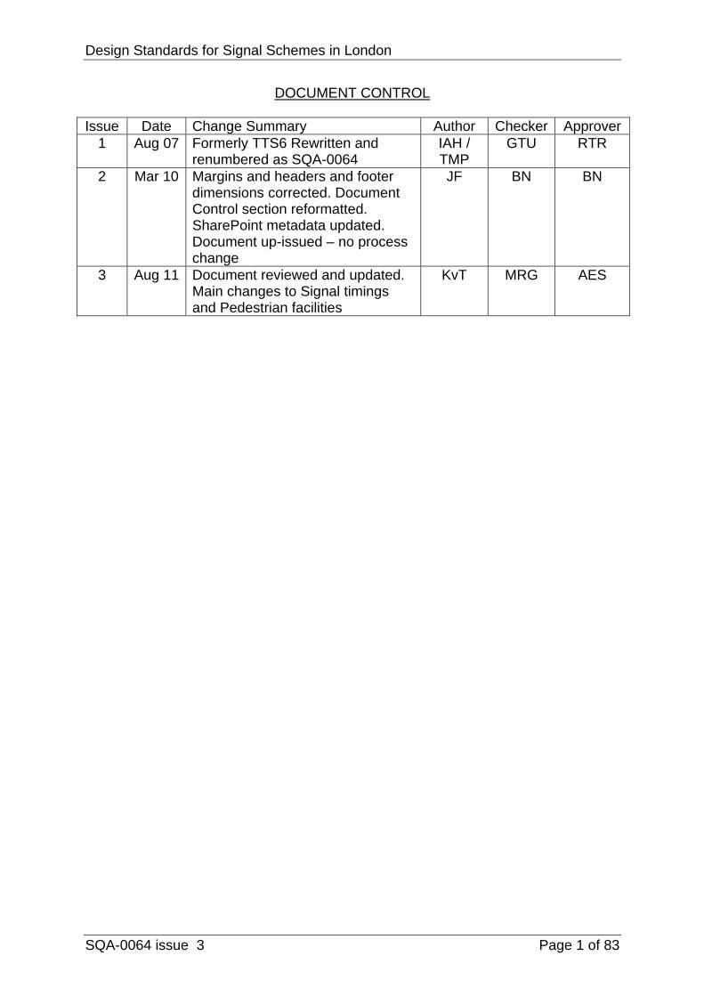
DOCUMENT CONTROL Issue Date Change Summary Author Checker Approver
1 Aug 07 Formerly TTS6 Rewritten and renumbered as SQA-0064
IAH / TMP
GTU RTR
2 Mar 10 Margins and headers and footer dimensions corrected. Document Control section reformatted. SharePoint metadata updated. Document up-issued – no process change
JF BN BN
3 Aug 11 Document reviewed and updated. Main changes to Signal timings and Pedestrian facilities
KvT MRG AES
Design Standards for Signal Schemes in London
Page 2 of 85
LIST OF CONTENTS Page 1. Introduction ............................................................................... 4
2. Design Requirements ............................................................... 8
3. Junctions .................................................................................. 13
4. Stand alone crossings (Pelican, Toucan or Puffin) ................... 28
5. Pelicans .................................................................................... 33
6. Toucans .................................................................................... 34
7. Puffins ...................................................................................... 35
8 Pedestrian crossing facility (Ped-X) ........................................... 36
8. Documentation for design file .................................................... 37
LIST OF FIGURES
Figure 1 – Design process ................................................................. 7
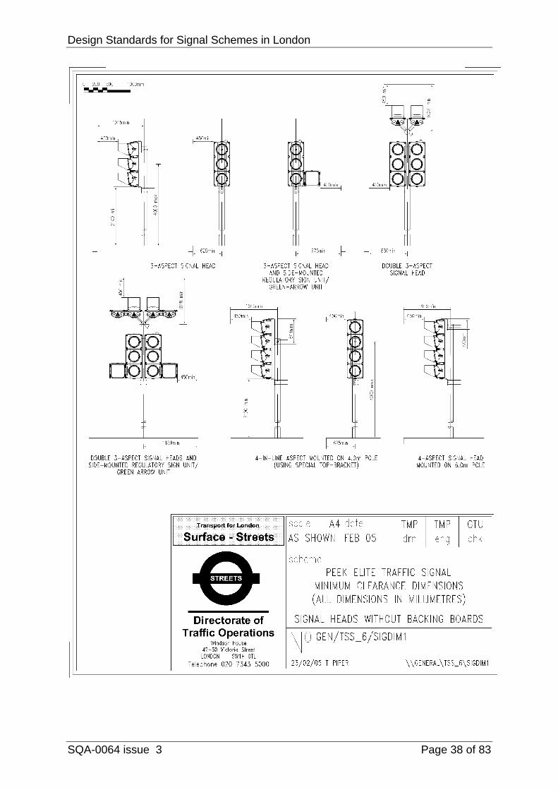
GEN/TSS_6/SIGDIM1 – Traffic Signal Minimum Clearance Dimensions – Signal Heads without Backing Boards ....................... 38
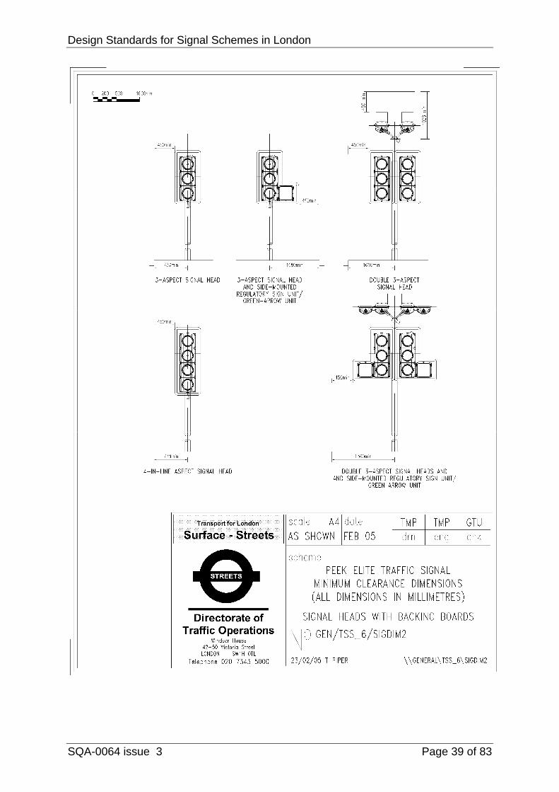
GEN/TSS_6/SIGDIM2 – Traffic Signal Minimum Clearance Dimensions – Signal Heads with Backing Boards ............................ 39
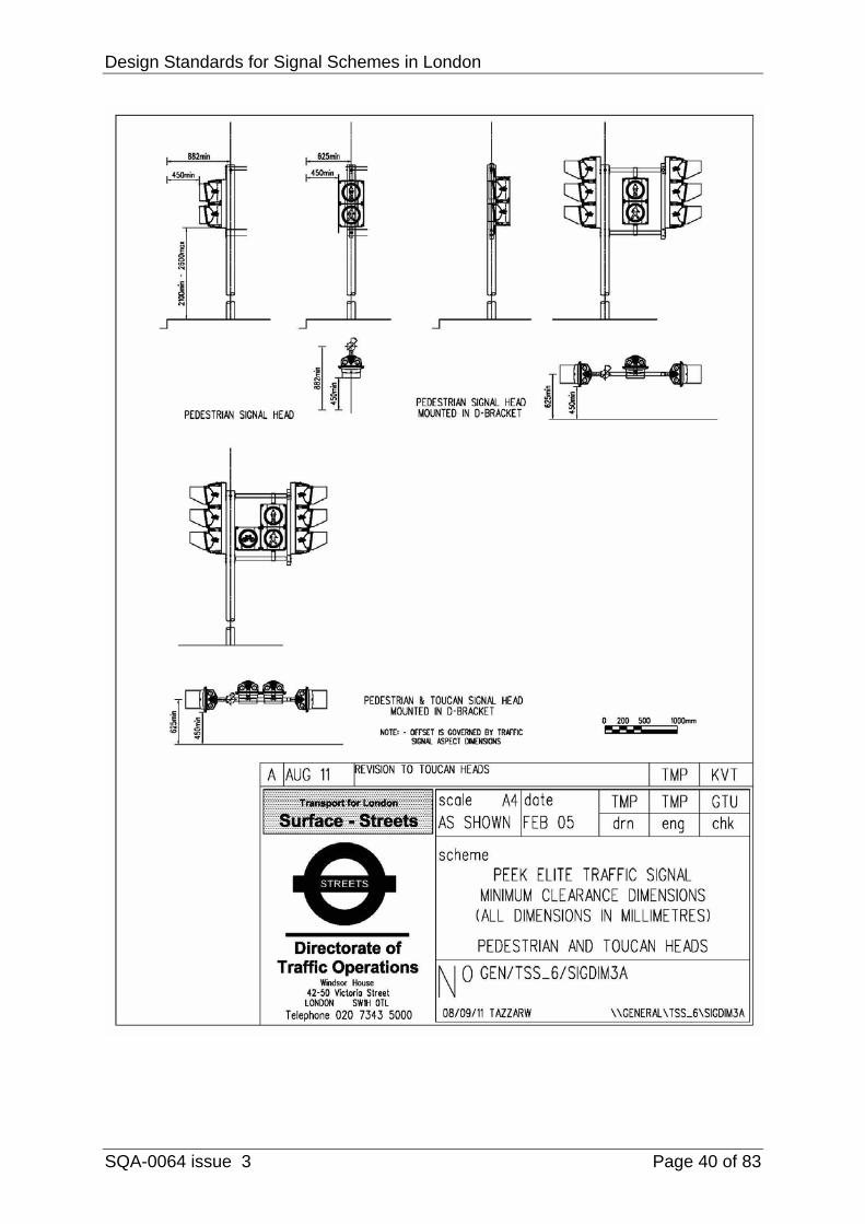
GEN/TSS_6/SIGDIM3 – Traffic Signal Minimum Clearance Dimensions – Pedestrian and Toucan Heads .................................. 40
GEN/TTS_06/FIG01 – Example of Proposed Layout Drawing ......... 41
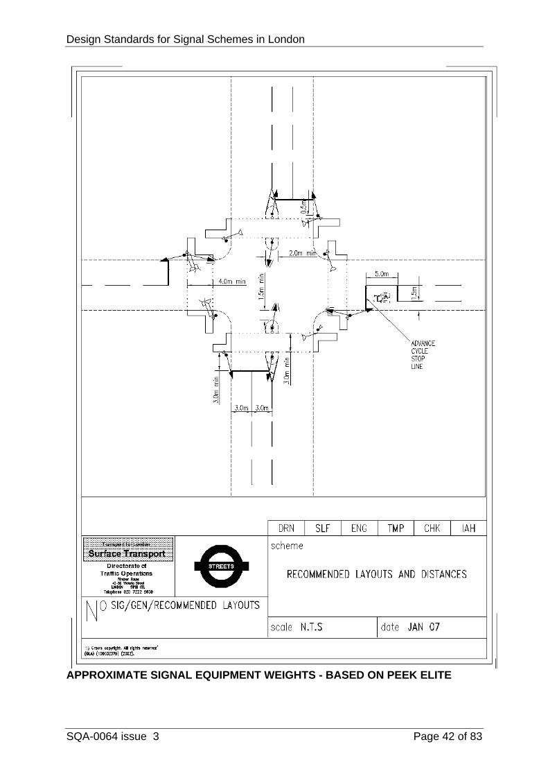
GEN/RECOMMENDED LAYOUTS – Recommended Layouts .......... 42
APPROXIMATE SIGNAL EQUIPMENT WEIGHTS ........................... 42
LIST OF APPENDICES
A. Drawing Checklist ...................................................................... 44
B. Data Requirements for the Operation of Computer Programs ... 45
C. TfL TD Scheme Brief Form ....................................................... 47
D. Stand alone crossings – site assessment record sheet ............. 49
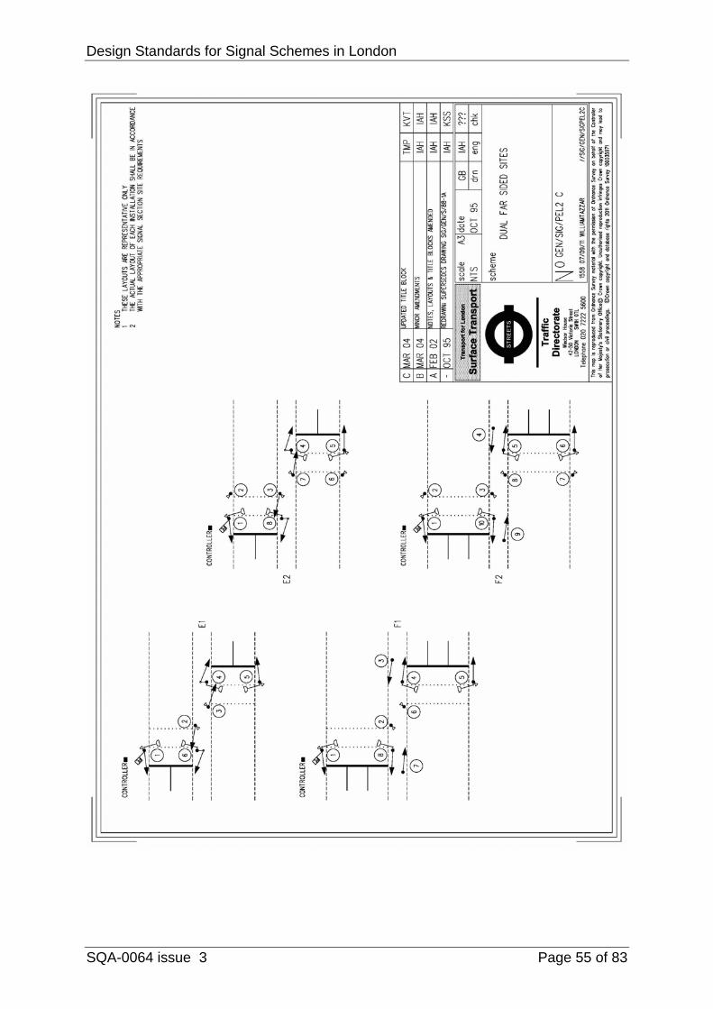
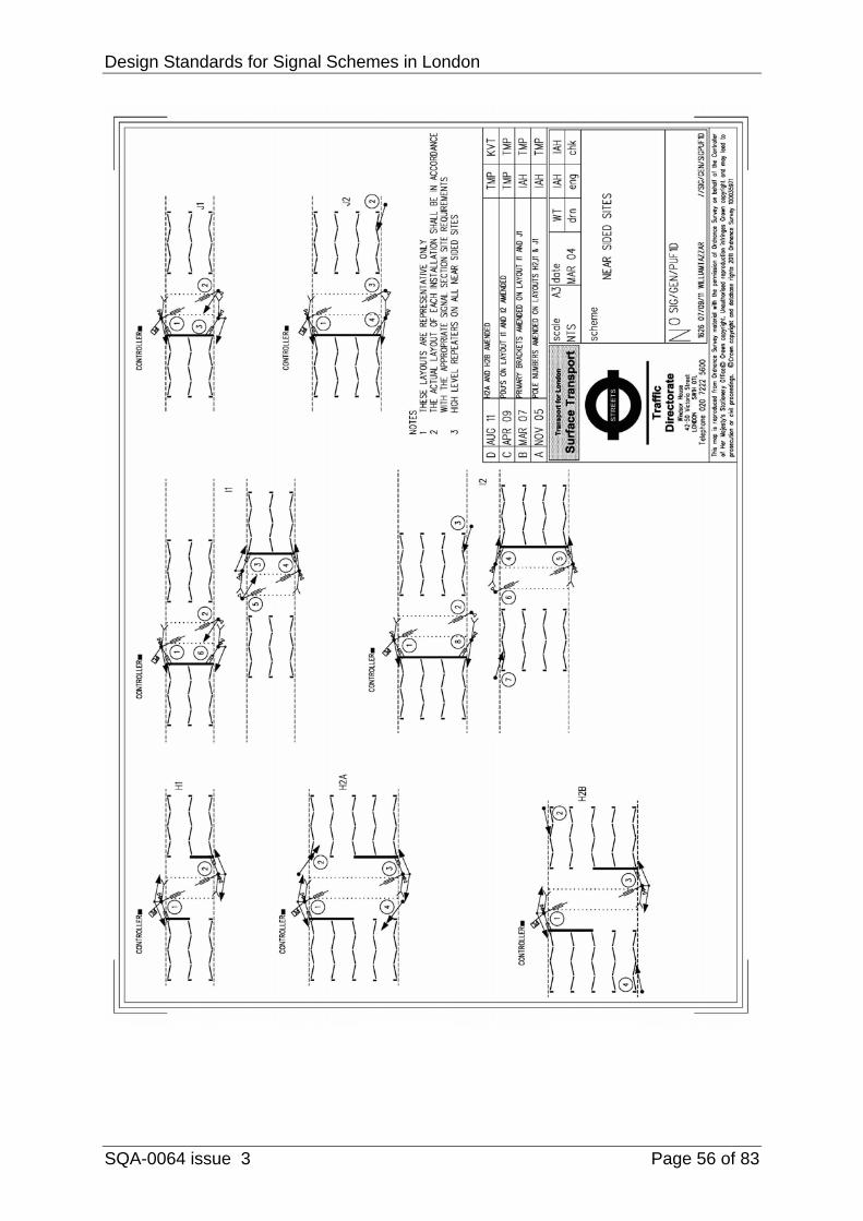
E. Preferred Layouts for Stand alone crossings ............................. 54
F. Pelican Timings - Greater London Area ................................... 57
G. Puffin or Nearside Timings – Greater London Area ................... 59
H. Calculation of Pedestrian Timings ............................................ 61
I. Safety Check List - Stage 1 (Predesign, on site) ...................... 63

Design Standards for Signal Schemes in London
SQA-0064 issue 3 Page 3 of 83
J. Design/Safety check Check List - St 2 (Scheme drawing check) 66
K. Design/Safety check Check List - St 3 (Commissioning ............ 71
L. Justification for Traffic Signals ................................................... 74
M. References ................................................................................ 80

Design Standards for Signal Schemes in London
SQA-0064 issue 3 Page 4 of 83
1 INTRODUCTION
1.1 SCOPE 1.1.1 The purpose of this document is to provide standards and guidance for
the design of traffic signals and associated equipment in London.
1.2 RELATION TO NATIONAL STANDARDS AND ADVICE 1.2.1 Whilst the Department for Transport (DfT) Specifications (TD), Advice
Notes (TA) Traffic Advisory Leaflets (TAL) and Local Transport Notes (LTN) (see references) set out the general design principles to be observed they give only limited advice on the location of signals, detectors, road markings, etc. Therefore, where the advice allows for flexibility in design and layout, this document sets out the standards to be used in London to provide consistency in design. It also gives guidance on the design processes for traffic signals and associated equipment to supplement the general information on good practice, which is given in TA 84/06 “Code of Practice for Traffic Control and Information Systems for All-Purpose Roads”.
1.3 POLICY CONTEXT
1.3.1 The Mayor’s Transport Strategy and the Transport for London and
London borough Local Transport Plans seek to reduce congestion, improve safety, improve the environment and promote more use of the road network by pedestrians, cyclists and buses.
1.3.2 Conflicts occurring between different streams and categories of road user
decrease the operational efficiency of junctions and increase the likelihood of accidents. Traffic signals can reduce such conflicts by separating movements in time and controlling their position on the road in a way which allows traffic performance to be regulated safely. They have the flexibility to assist traffic on specific roads, to assist different categories of road users and to respond to different traffic conditions. When their timings are co-ordinated with adjacent signal installations, they can be used to influence the pattern and speed of traffic in an area.
1.3.3 Traffic signals and their associated equipment provide, therefore, an
effective means by which traffic managers can implement their authority’s transport policies.
1.3.4 The Traffic Directorate (TD) – Traffic Infrastructure (TI) has been working
with London Councils to prepare a paper setting-out an agreed justification criteria for new traffic signal installations. All clients are asked to observe these criteria, set-out in Appendix L. TD is happy to work with any client to determine if these criteria are not met for any proposal they might wish to consider.
Design Standards for Signal Schemes in London
SQA-0064 issue 3 Page 5 of 83
1.4 ROLE OF TRAFFIC DIRECTORATE 1.4.1 In accordance with the GLA 1999 Road Traffic Act clause 276, Transport
for London (TfL) is the traffic authority for traffic signals on the Transport for London Road Network (TLRN), the Strategic Road Network (SRN) and on roads for which the London boroughs are the highway authority. Where traffic signals are installed on roads for which a London borough is the highway authority, TfL consults with that borough before making major changes to the signal timings and permits reasonable requests from the borough for modifications to existing traffic signals and the provision of new signals. Traffic Infrastructure (TI) of the Traffic Directorate (TD) is that part of TfL, which is responsible for the design, installation, and commissioning of traffic signal and associated equipment.
1.4.2 The Network Performance Team within the TD (TD–NP) is responsible for
maximising and safeguarding the efficient operation of London’s computer controlled road network. Its primary focus is to maintain a balance for all road users.
1.4.3 TIS carries out much of the design, operation and supervision of installation works in-house whilst the majority of the installation and maintenance work on site is carried out by contractors appointed by competitive tendering.
1.4.4 The initial concept or feasibility design, some of the preliminary design,
impact assessment and cost justification of the scheme are usually carried out by the organisation promoting the scheme. This organisation is also responsible for obtaining any traffic orders required and for the design and management of civil engineering works required for the scheme.
1.4.5 When requested, TI provides comments on these preliminary designs and
should always be consulted about the method of control to be used. TI usually carries out the detailed design work but the promoting authority may also carry out this work. In this event, the completed design must be checked and approved by TI before work on the procurement and installation of the scheme commences and the completed installation must also be checked and approved by TI before it is commissioned. TIS should be in attendance at the commissioning.
1.5 DESIGN PROCEDURES 1.5.1 In order to comply with registered Quality Assurance procedures, Health
and Safety legislation and the Construction (Design and Management) Regulations it is necessary for design checks to be carried out at various stages in the design process and for any documentation pertinent to the
Design Standards for Signal Schemes in London
SQA-0064 issue 3 Page 6 of 83
subsequent operation, maintenance and removal of the equipment to be made available to those responsible for these activities.
1.5.2 Advice on best practice and procedures associated with the safety
aspects of a scheme is given in TA 84/06, “Code of Practice for Traffic Control and Information Systems for All-Purpose Roads”. This advice and guidance should be followed by those responsible for the design of a traffic control scheme incorporating traffic signals.
1.5.3 In order to comply with the requirements of the Construction (Design and
Management) Regulations 2007, a design file of basic information and certification for such a scheme is produced during the design process to provide a record of the development of the scheme, the decisions made and the safety considerations. This design file is incorporated in a Health and Safety Plan, which also contains records of the construction process and which is passed on to the organisation responsible for maintaining the section of highway affected by the scheme. As part of this process, a Site Installation Commentary must be carried out for each scheme, information on this process can be found in TfL Guidance Note No. GN/TO/008 – Site Installation Commentary.
1.5.4 Traffic signals in London are presently maintained by different contractors
to those maintaining the highway and a separate traffic signal design file is therefore maintained by TI for each signal scheme. Figure 1 depicts the overall design process recommended in TA 84/06, the information which should be kept on the scheme design file, the interaction required between the overall scheme designers and TI and the information which should be placed on the signal design file held by TI. In order to comply with quality assurance procedures, it is necessary for the control strategy of the signal installation to be agreed by TD-NP at an early stage in the preliminary design process and for the signal design and drawings to be formally authorised by TI.
1.5.5 The concept, preliminary and detailed design stages should be carried out
in accordance with the recommendations of TA 84/06. Additional guidance on design requirements in London is, however, given in the following chapters of this specification.

Design Standards for Signal Schemes in London
SQA-0064 issue 3 Page 7 of 83
Figure 1: Design Process
Design Standards for Signal Schemes in London
SQA-0064 issue 3 Page 8 of 83
2 DESIGN REQUIREMENTS
2.1 OBJECTIVE 2.1.1 The initial objective of the signal design exercise is to produce a proposed
scheme drawing that will enable the Stage 2 Design/Safety Check to be completed. This drawing will show the proposed signal layout, method of control and ducting system. It will include a detailed 1:200 scale insert showing all relevant local details together with all existing and proposed TfL plant and equipment. If required, a 1:500 scale insert of outline detail showing detectors/loops on all approaches will also be included. An example of a proposed scheme drawing is shown in drawing number GEN/TTS_06/FIG01. A checklist of items to be included on a proposed scheme drawing is given at Appendix A.
2.2 DESIGN OF SIGNAL SCHEMES
2.2.1 A design brief is required for each scheme. This should consist of a
statement of the objectives of the scheme with the reasons for them. This brief must include a list of all the facilities required and any particular design requirements necessary as a result of local factors.
2.2.2 At an early stage TI should be consulted to establish whether:-
i) Network Assurance notification is required
ii) The installation is to be controlled centrally from the UTC computer and if so the restrictions this will place on the design, particularly on the cycle time.
2.2.3 Where TI is requested to carry out the design of the traffic signal scheme,
the client should complete a Scheme Brief Form (Appendix C) which details the information required for the design of the scheme.
2.2.4 Where a site is being modernised by TI, the following statements shall
apply:
(i) All instructions set-out in this document shall be followed (ii) Where practicable and requested by the Highway authority,
additional facilities shall be incorporated in the design (i.e. new pedestrian facilities).
(iii) Where there are existing facilities at a site, these should not be removed without agreement with the Highway Authority.
(iv) The pedestrian timings to be used shall be as set-out in this document.
Design Standards for Signal Schemes in London
SQA-0064 issue 3 Page 9 of 83
2.3 DESIGN CHECK 2.3.1 All signal schemes are required to have a design/safety check and TI
carries out an independent check when the design has been completed. 2.3.2 The Design/Safety check is carried out in three stages:
Stage 1 a pre-design inspection of the proposed site to identify possible problems that would have a bearing on the design of the scheme;
Stage 2 a Design/Safety check of the design carried out by the TI
checking engineer;
Stage 3 a site inspection carried out at commissioning to check that any problems identified in Stages 1 and 2 have been overcome and no other problems have occurred. If the site has been installed by a third party, TIS must attend the inspection.
2.3.3 The Design Engineer shall visit the site before any design work is started
and carry out STAGE 1 of the Design/Safety check by filling in the Design/Safety Check List (DSCL) (see Appendix I) in any colour other than red ink, making any comments or suggestions in the appropriate column and then sign the document.
2.3.4 A preliminary Site Installation Commentary (SIC) should also be carried out at this time.
2.3.5 Photographs of each approach would also be beneficial.
Note: On a green field site this may not be very productive but often problems can be anticipated.
2.3.6 The Design Engineer should then prepare the proposed scheme layout
drawing (in accordance with TTS 14) incorporating any features identified in the DSCL.
2.3.7 If any feature mentioned in the DSCL cannot be incorporated into the
design then the reasons must be noted in red ink on the DSCL alongside the appropriate comment.
2.3.8 When the scheme layout drawing is complete it shall be sent to the TIS
Checking Engineer together with the DSCL and the controller specification detailing the method of control, the intergreen and minimum green timings, and any phase delays. Where the design is for a Pelican, Puffin or Toucan installation the proposed timings should also be sent with the scheme drawing and SCL.

Design Standards for Signal Schemes in London
SQA-0064 issue 3 Page 10 of 83
2.3.9 The TIS Checking Engineer will carry out STAGE 2 of the Design/Safety check by checking the layout against the Design/Safety Check List (DSCL) STAGE 2 (see Appendix J), marking the list in blue ink. The TIS Checking Engineer will respond to the comments of the Design Engineer on the DSCL STAGE 1 in red ink or, if satisfied, initial the Check box on the DSCL STAGE 1.
2.3.10 If any amendments to the design, as suggested by the Checking Engineer
at STAGE 2, cannot be incorporated into the scheme, then the Design Engineer will respond to the comments of the Checking Engineer on the DSCL STAGE 2 in red ink. Where necessary evidence should be provided to show that the Highway Authority are in agreement with the final design.
2.3.11 If, subsequent to STAGE 2 of the check, modifications are made to the
layout, the drawing shall be resubmitted to the Checking Engineer for checking and clearance.
2.3.12 If in agreement with the DSCL STAGE 2 document, the Checking
Engineer and Design Engineer will both sign it. 2.3.13 A detailed Site Installation Commentary (SIC) should also be carried out
at this time. 2.3.14 If any disputes occur between the Checking Engineer and the Design
Engineer that cannot be mutually resolved, the matter shall be referred to a Team Leader in TIS or, if not available, to the Chief Engineer Signals.
2.3.15 When the STAGE 2 Design/Safety Check of the scheme layout drawing
has been carried out satisfactorily, the Checking Engineer shall confirm the result by dating and initialling the master proposed drawing in the box provided.
2.3.16 The STAGE 2 Design/Safety Check of both the scheme drawing and the
controller specification must be completed before the controller is ordered. 2.3.17 When the scheme is installed, the Design Engineer and TI shall carry out
STAGE 3 of the Design/Safety check on site and complete the DSCL for STAGE 3 (see Appendix K) in any colour other than red ink and then sign it. This can be undertaken by TIS exclusively.
2.3.18 If any safety implications are found at this point Design Engineers will use
their discretion and note the outcome on STAGE 3 of the safety check list and take any appropriate remedial action.
2.4 BASIC SITE INFORMATION
2.4.1 The designer should visit the site and note any particular safety features
necessary, carrying out a preliminary STAGE 1 Design/Safety check by considering all the factors on the Design/Safety Check List the designer

Design Standards for Signal Schemes in London
SQA-0064 issue 3 Page 11 of 83
should also assess the need for any non-standard information that needs to be provided.
2.4.2 The following information will be required to carry out the design:
a) An electronic 1:200 scale plan of the site should be sent to: – [email protected] in DWG. format. If the scheme is an ‘improvement’, the new, as well as the existing, kerb and building lines should be shown. For schemes that entail no significant alteration to road kerb lines, base ordnance survey data may provide sufficient topographical information but care should be exercised to ensure that the details are both current and accurate. Limited surveys to check certain critical dimensions and to check the location of any physical objects such as statutory undertaker’s plant, manhole covers, drainage, lighting cables, lamp columns, road signs, trees etc may be all that is required. For more significant changes in layout, a full three dimensional model of the existing topography may be required. For major changes early consultation with statutory undertakers, who may be affected, is recommended. These consultations may lead to a requirement to commission trial excavations to locate precisely existing plant in relation to the revised kerb alignments.
Hourly classified traffic counts, converted to PCU’s/hour (reassigned if the scheme is part of a traffic management package) for each arm of the junction with separate turning traffic figures. These counts should cover the morning and evening peaks, daytime off-peak and any other significant event time, e.g. Saturday shopping period. If the existing situation has queues, their length, in vehicles, should be measured every quarter of an hour. The flows should be in the form of a graphical summary if possible. If major changes to the road network, developments or other factors are likely to result in changed traffic flows, predicted flows from traffic models should be provided.
b) The saturation flow of each arm of the junction should be assessed, either practically by on site measurement using the TRL saturation flow program and a portable computer, or theoretically using the TRL method described in TRL RR 67 ‘Prediction of saturation flows for road junctions controlled by traffic signals’. Saturation flows should wherever possible be measured practically on site but it is essential at critical junctions. The prediction method may be used as an alternative where site measurement is impractical.
c) Cruise speed - the 85 percentile free flow traffic platoon running
speed for each approach. Where the junction forms part of a linked network the following is also required:- Journey time – free flow traffic platoon time (seconds) from up-stream stop line to junction stop line.
Design Standards for Signal Schemes in London
SQA-0064 issue 3 Page 12 of 83
e) For all proposed installations 85th percentile speeds should be provided so that suitable detection can be determined.
f) Statutory undertakers’ drawings should be provided for all
proposed designs. 2.4.3 TD–NP must be consulted on the design and timing constraints of any
scheme, to establish whether computer control is required.
Design Standards for Signal Schemes in London
SQA-0064 issue 3 Page 13 of 83
3 JUNCTIONS
3.1 CHOICE OF CONTROL METHOD 3.1.1 Consideration must be given to the policy requirements of the highway
authority and Transport for London. The designer should in particular consider the requirements of pedestrians, cyclists and public transport.
3.1.2 All installations shall be designed to operate in an isolated mode and any
other mode required by the client. For individual signal installations outside the UTC area the isolated mode would normally be VA or MOVA. For junctions in the UTC area the isolated mode would normally be the Cableless Linking Facility (CLF) with due regard to adjacent junctions. The fallback system from CLF would be either VA or fixed time operation.
3.1.3 If there are bus routes passing through the scheme with a minimum of 4
buses per hour on any one approach then Bus Priority should be included. TI will advise on the equipment to be provided. To provide maximum efficiency, if the junction has bus lanes on any approach, then the timings will need to be matched to the set back of the bus lane. (TfL Guidance Note No: GN/TO/001 – Bus Priority Implementation within UTC and Userguide No. U/2706/TO/382 – Selective Vehicle Detection in London)
3.1.4 MOVA control (TD 35/91) may be a requirement at signals on the TLRN
outside the UTC area and the relevant TfL borough managers should be consulted. In such cases MOVA should be the normal mode of operation and in the event of failure the junction should revert to vehicle actuated control using the MOVA detection loops.
3.1.5 TRL MOVA Application Guides 44 and 45 should be used when designing
a MOVA installation. 3.1.6 When the junction is in the SCOOT area TD-UTC will define the detection
type, its location and the ducting requirements.
3.2 DESIGN 3.2.1 All junctions shall be designed in accordance with the client’s specific
requirements. 3.2.2 The detailed analysis of the performance of a traffic signalled junction is
helped by the use of a computer program. The use of a computer program should always be considered as an aid to the design of an individual junction or network. Additional factors must be taken into account to achieve a good design, such as turning radii, lane widths, visibility, signing, environmental considerations and plain common sense.
Design Standards for Signal Schemes in London
SQA-0064 issue 3 Page 14 of 83
3.2.3 LINSIG is the preferred software package used by TI engineers, being the most straightforward to use and able to model phase based types of controller. It is recommended for use in London as it is capable of modelling accurately different forms of flared approach, allows for parked vehicles, bus lanes and can take into account the number of right turn pcu’s (passenger car units) stored in front of the stop line, and can predict the capacity of this movement with or without a right turn indicative signal. Any permitted stage sequence can be run with the traffic model and all constraints of controller data will apply. A list of data requirements for the operation of a computer program is given at Appendix B.
3.2.4 The stage structure selected must deal not only with the junction in its
normal operating condition but also cater for contingency and non-optimum working.
3.2.5 Local linking to adjacent signals should always be considered in the
design, particularly for Pelicans, Puffins, Toucans and Ped-X crossings, but local factors will influence this decision. The link timings should be provided with the information required for the STAGE 2 Design/Safety check.
3.2.6 Where fixed time plans are required to co-ordinate a signal controlled
network TRANSYT and VISSIM are the only acceptable methods of optimising the timings.
3.3 PEDESTRIAN FACILITIES AT JUNCTIONS (see reference TAL 5/05) 3.3.1 Where pedestrian facilities are being provided, audible and/or tactile
devices must be provided for the visually impaired in addition to the normal Red and Green Man indication. The tactile or audible devices shall always operate at the same time as and be interlocked with the Green Man indication.
3.3.2 In sensitive residential areas it may be necessary to inhibit the audible by
time switch between the hours of 23.00 – 07.00 or other appropriate times.
3.3.3 All tactile paving and dropped kerbs are to be constructed in accordance
with “Guidance on the Use of Tactile Paving Surfaces” (DETR 1998) and any specific requirements of the highway authority. It should be noted that tactile surfacing is not recommended within pedestrian refuges or separation islands where the signal staging is intended to allow pedestrians to cross the whole width of the carriageway in one movement. (DMRB Vol 6 Section 2 Part 3 - TD 50/04 - para 4.14)
3.3.4 Tactile units generally only need to be installed in the right hand push
button as you are facing the crossing. Where there is a central refuge on a crossing there should ideally be two push buttons on the refuge, both fitted with tactile units.(TAL 5/05 Part 3).

Design Standards for Signal Schemes in London
SQA-0064 issue 3 Page 15 of 83
3.3.5 To ensure consistency for visually impaired people the tactile unit should
be installed on the right hand side of the bottom of the push button unit. (Inclusive mobility Para 3.12)
3.3.6 Red Lamp Monitoring must be provided to monitor any vehicle phase that
conflicts with a pedestrian phase when audible and/or tactile facilities have been installed (in accordance with section 3.3.1).
3.3.7 It is preferable for audible devices to only be installed where there is a full
pedestrian stage at which all the pedestrian indications appear at the same time on the same phase and there are no additional pedestrian phases
3.3.8 However it is becoming increasingly difficult to include all the necessary
signals on a single phase card without overloading it and it is now possible, through special conditioning, to allow audible signals at a full pedestrian stage comprised of more than one phase. It is important to ensure that the audible signal is not activated until all the phases have started and that there is time to provide an adequate invitation period for those relying on the audible signal. The audible signal must not continue past the end of the first green man to finish. Advice should be sought from TI on the necessary special conditioning.
3.3.9 In the following circumstances, only tactile devices shall be used, since
audible signals would be unsafe:
a) When parallel pedestrian phases are provided; or
b) When a full pedestrian stage is provided and the appearance of the various pedestrian phases are staggered to take account of clearing traffic such that 3.3.7 or 3.3.8 cannot be applied.
3.3.10 Where parallel pedestrian crossings are displaced from the junction, a
stop line and associated traffic signals should normally be provided for the protection of pedestrians. Detailed site requirements may need discussion with the client. Care should be taken to ensure the parallel pedestrian phase operates at a suitable time.
3.3.11 Where audible and/or tactile devices are provided for parallel crossings
without the protection of a stop line, ‘All Red’ extending detectors may be desirable to inhibit the pedestrian signal while vehicles are still on the crossing.
3.3.12 If ‘All Red’ detectors are used in a cableless linked system or in UTC care
must be taken in arranging the group timings in order to prevent stage skipping.
3.3.13 For both non UTC and UTC installations all round pedestrian stages
should only appear if demanded and a parallel pedestrian phase should
Design Standards for Signal Schemes in London
SQA-0064 issue 3 Page 16 of 83
normally only appear if a demand is present at the start of the preceding interstage.
3.3.14 At an installation in the UTC area where the pedestrian phases has been configured to always appear, push button must be provided to ensure that tactile units can be facilitated. Where the vehicle phase does not have detection the push button will not insert a demand but the ‘WAIT’ indicator should illuminate when a button has been pressed (and the Green Man is not lit).
3.3.15 Where there is a pedestrian phase in parallel with a vehicle phase that is
detector demanded, the UTC demand bit (DX) shall be specified to demand both traffic and any parallel pedestrian phase, i.e. STAGE DEMAND.
3.3.16 Pedestrian push button units associated with far side signals should
normally be mounted at an angle of 45˚ to the kerb line with the base of the unit 1.0m from the surface of the footway. Where near side signals are used they should generally be mounted at an angle of 25-30˚ to the kerb line. See recommendations in TAL 1/02 The Installation of Puffin Pedestrian Crossings and Puffin Good Practice Guide.
3.3.17 PEDESTRIAN TIMINGS
There is flexibility in the interpretation of the Green-Man invitation period for signal controlled junctions. The following statement is the bass for pedestrian timings and is consistent with DfT guidance
“Pedestrian timings should enable waiting pedestrians (who commence their crossing at some point during the invitation period) to cross the carriageway in a single movement, without stopping or turning back.
Waiting pedestrians are further defined as the standing queue of pedestrians as observed at the start of the green-man”
3.3.18 Figures 1 and 2 show the process maps that are to be followed when
determining the green-man invitation period for existing sites. Figure 1 relates to far-sided aspects and Figure 2 relates to near-sided pedestrian aspects.
3.3.19 Where there is a considerable distance between a pedestrian facility and
the conflicting traffic stopline; consideration should be given to reducing the intergreen following the pedestrian phase to take into this travelling time into account. Calculations regarding such reductions must be documented, accepted by the Stage 2 Design/Safety Check and confirmed by a Team Leader or the Chief Engineer Signals before they are adopted for the design.

Design Standards for Signal Schemes in London
SQA-0064 issue 3 Page 17 of 83
Figure 1 – Process Map for Junctions – Far-sided
Figure 2 – Process Map for Near-sided signals
Design Standards for Signal Schemes in London
SQA-0064 issue 3 Page 18 of 83
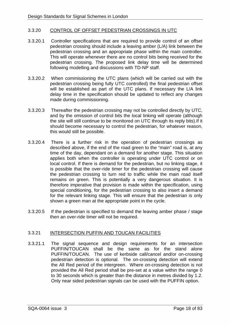
3.3.20 CONTROL OF OFFSET PEDESTRIAN CROSSINGS IN UTC 3.3.20.1 Controller specifications that are required to provide control of an offset
pedestrian crossing should include a leaving amber (L/A) link between the pedestrian crossing and an appropriate phase within the main controller. This will operate whenever there are no control bits being received for the pedestrian crossing. The proposed link delay time will be determined following modelling and discussions with TD-NP staff.
3.3.20.2 When commissioning the UTC plans (which will be carried out with the pedestrian crossing being fully UTC controlled) the final pedestrian offset will be established as part of the UTC plans. If necessary the L/A link delay time in the specification should be updated to reflect any changes made during commissioning.
3.3.20.3 Thereafter the pedestrian crossing may not be controlled directly by UTC, and by the omission of control bits the local linking will operate (although the site will still continue to be monitored on UTC through its reply bits).If it should become necessary to control the pedestrian, for whatever reason, this would still be possible.
3.3.20.4 There is a further risk in the operation of pedestrian crossings as described above, if the end of the road green to the “main” road is, at any time of the day, dependant on a demand for another stage. This situation applies both when the controller is operating under UTC control or on local control. If there is demand for the pedestrian, but no linking stage, it is possible that the over-ride timer for the pedestrian crossing will cause the pedestrian crossing to turn red to traffic while the main road itself remains on green. This is potentially a very dangerous situation. It is therefore imperative that provision is made within the specification, using special conditioning, for the pedestrian crossing to also insert a demand for the relevant linking stage. This will ensure that the pedestrian is only shown a green man at the appropriate point in the cycle.
3.3.20.5 If the pedestrian is specified to demand the leaving amber phase / stage then an over-ride timer will not be required.
3.3.21 INTERSECTION PUFFIN AND TOUCAN FACILITIES 3.3.21.1 The signal sequence and design requirements for an intersection
PUFFIN/TOUCAN shall be the same as for the stand alone PUFFIN/TOUCAN. The use of kerbside call/cancel and/or on-crossing pedestrian detection is optional. The on-crossing detection will extend the All Red period of the intergreen. Where on-crossing detection is not provided the All Red period shall be pre-set at a value within the range 0 to 30 seconds which is greater than the distance in metres divided by 1.2. Only near sided pedestrian signals can be used with the PUFFIN option.

Design Standards for Signal Schemes in London
SQA-0064 issue 3 Page 19 of 83
3.4 JUNCTION LAYOUT 3.4.1 PRIMARY AND SECONDARY SIGNALS (see ref TA 12/81, TD 50/04,
TAL 1/06,) 3.4.1.1 The Traffic Signs Regulations and General Directions 2002 (TSRGD
2002) requires all junctions to have at least two signal heads per approach.
3.4.1.2 The primary signal post is located 2.5m beyond the stop line normally on the near side of each approach and 0.5m from any pedestrian studs. Two primary signals are preferred for approaches wider than one lane.
3.4.1.3 Secondary signals typically have the same information as the primary
and may have additional information, which must not conflict with that shown on the primary signal.
3.4.1.4 At least one secondary signal should be provided on each approach so
that the signal is visible from the centre of the stop line. It should normally be sited within an arc of 30° to the offside from the centre of the stop line.
3.4.1.5 The secondary signal should be sited no further than 50m from its relative
stop line. (TA 50/04 Para 2.64) 3.4.1.6 Closely associated secondary signals should be considered when it is
inadvisable for pedestrians or certain streams of traffic to see the secondary signals.
3.4.1.7 They must always be considered on the approach opposite one with a right turn overlap facility. Closely Associated signals do not have to be provided where the approach opposed one with a right turn overlap has a prohibited right turn Traffic Regulation Order in place, and is signed with the appropriate regulatory box sign.
3.4.1.8 Consideration should be given to the reduction of street furniture by
incorporating signal heads on to lamp columns where appropriate. Advice can be sought from the TD Electrical Design Team on the measures necessary to achieve suitable design.
3.4.1.9 The layout of green arrows on signal heads must be in accordance with
Diagrams 3000.7 & 3000.8 of TSRGD 2002.
Design Standards for Signal Schemes in London
SQA-0064 issue 3 Page 20 of 83
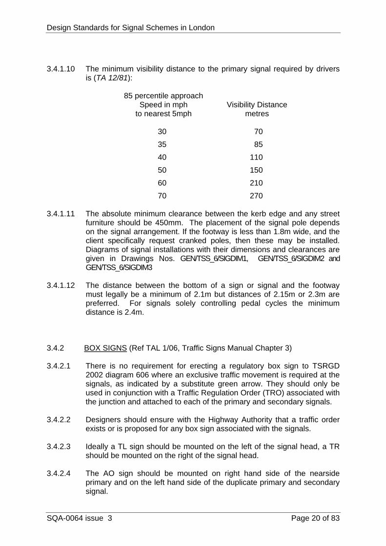
3.4.1.10 The minimum visibility distance to the primary signal required by drivers is (TA 12/81):
85 percentile approach Speed in mph Visibility Distance to nearest 5mph metres 30 70 35 85 40 110 50 150 60 210 70 270 3.4.1.11 The absolute minimum clearance between the kerb edge and any street
furniture should be 450mm. The placement of the signal pole depends on the signal arrangement. If the footway is less than 1.8m wide, and the client specifically request cranked poles, then these may be installed. Diagrams of signal installations with their dimensions and clearances are given in Drawings Nos. GEN/TSS_6/SIGDIM1, GEN/TSS_6/SIGDIM2 and GEN/TSS_6/SIGDIM3
3.4.1.12 The distance between the bottom of a sign or signal and the footway
must legally be a minimum of 2.1m but distances of 2.15m or 2.3m are preferred. For signals solely controlling pedal cycles the minimum distance is 2.4m.
3.4.2 BOX SIGNS (Ref TAL 1/06, Traffic Signs Manual Chapter 3) 3.4.2.1 There is no requirement for erecting a regulatory box sign to TSRGD
2002 diagram 606 where an exclusive traffic movement is required at the signals, as indicated by a substitute green arrow. They should only be used in conjunction with a Traffic Regulation Order (TRO) associated with the junction and attached to each of the primary and secondary signals.
3.4.2.2 Designers should ensure with the Highway Authority that a traffic order exists or is proposed for any box sign associated with the signals.
3.4.2.3 Ideally a TL sign should be mounted on the left of the signal head, a TR should be mounted on the right of the signal head.
3.4.2.4 The AO sign should be mounted on right hand side of the nearside primary and on the left hand side of the duplicate primary and secondary signal.

Design Standards for Signal Schemes in London
SQA-0064 issue 3 Page 21 of 83
3.4.2.5 All versions of 606 may be mounted 4 in-line under the green arrow.
3.4.2.6 When required, NRT (612) and NLT (613) signs should be mounted, on
the relevant approach, on all signal heads alongside the green aspect. The NRT sign should be mounted to the right of the signal head and the NLT to the left hand side.
3.4.2.7 The following are the only signs allowed to be fixed to traffic signals as box signs.
At junctions the following are allowed:-
606 White arrow on blue background (AO,TL,TR) 612 NRT 613 NLT 614 No U-turn 616 No entry (Exceptional – Traffic Signs Manual Chapter 3 – para 6.2.5 – no indication in TSRGD 2002 for junctions)
The following ”exemption” plates may be added:- (Note: exemption plates should not be used with a 606 associated with a green arrow)
954.5 Except buses (may be varied to “Except cycles”) 954.6 Except buses & cycles (may be varied to “local buses” or “buses
& Taxis”) 954.7 Except buses, taxis & cycles (may be varied to “local buses &
cycles” or “local buses & taxis”)
3.4.3 HOODS AND LOUVRES 3.4.3.1 Louvres, long hoods or long cut-away hoods should be specified as
necessary to avoid ‘see through’ problems particularly where there may be internal stop lines in a junction. Advice on the circumstances, which warrant the use of vertical and horizontal louvers, can be obtained from TI. In no circumstances should louvers be used on red aspects. (TA 15/81)
3.4.4 MAST ARMS AND 6M POLES 3.4.4.1 Mast arm signals or alternatively 6m poles with dual signal heads should
only be provided where there is a visibility problem, for example, on wide roads or on adverse gradients.
3.4.4.2 On mast arm signals LED signal aspects should be used and primary hoods used on all aspects.
3.4.4.3 Backing boards must always be provided with outreach signals on Mast-Arms. (TR 2006A Paragraph 3.2)
Design Standards for Signal Schemes in London
SQA-0064 issue 3 Page 22 of 83
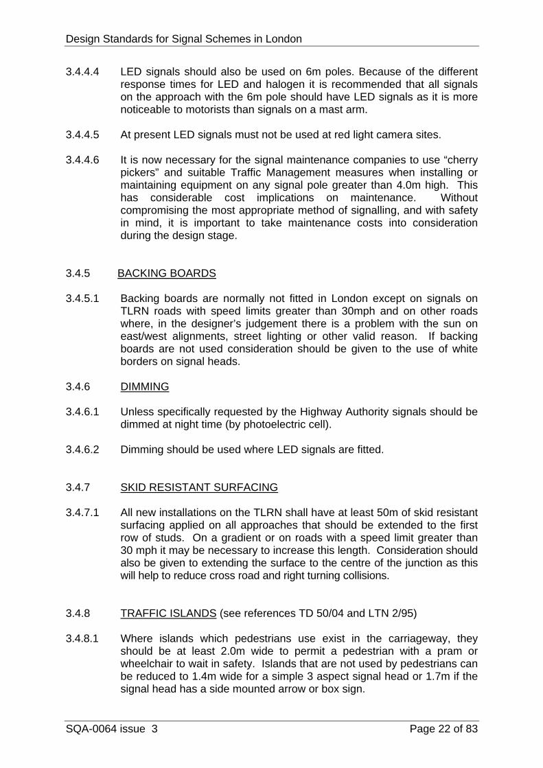
3.4.4.4 LED signals should also be used on 6m poles. Because of the different response times for LED and halogen it is recommended that all signals on the approach with the 6m pole should have LED signals as it is more noticeable to motorists than signals on a mast arm.
3.4.4.5 At present LED signals must not be used at red light camera sites. 3.4.4.6 It is now necessary for the signal maintenance companies to use “cherry
pickers” and suitable Traffic Management measures when installing or maintaining equipment on any signal pole greater than 4.0m high. This has considerable cost implications on maintenance. Without compromising the most appropriate method of signalling, and with safety in mind, it is important to take maintenance costs into consideration during the design stage.
3.4.5 BACKING BOARDS 3.4.5.1 Backing boards are normally not fitted in London except on signals on
TLRN roads with speed limits greater than 30mph and on other roads where, in the designer’s judgement there is a problem with the sun on east/west alignments, street lighting or other valid reason. If backing boards are not used consideration should be given to the use of white borders on signal heads.
3.4.6 DIMMING 3.4.6.1 Unless specifically requested by the Highway Authority signals should be
dimmed at night time (by photoelectric cell). 3.4.6.2 Dimming should be used where LED signals are fitted. 3.4.7 SKID RESISTANT SURFACING 3.4.7.1 All new installations on the TLRN shall have at least 50m of skid resistant
surfacing applied on all approaches that should be extended to the first row of studs. On a gradient or on roads with a speed limit greater than 30 mph it may be necessary to increase this length. Consideration should also be given to extending the surface to the centre of the junction as this will help to reduce cross road and right turning collisions.
3.4.8 TRAFFIC ISLANDS (see references TD 50/04 and LTN 2/95) 3.4.8.1 Where islands which pedestrians use exist in the carriageway, they
should be at least 2.0m wide to permit a pedestrian with a pram or wheelchair to wait in safety. Islands that are not used by pedestrians can be reduced to 1.4m wide for a simple 3 aspect signal head or 1.7m if the signal head has a side mounted arrow or box sign.

Design Standards for Signal Schemes in London
SQA-0064 issue 3 Page 23 of 83
3.4.8.2 Where there is a staggered pedestrian facility the island should be a
minimum of 3m wide. This can be reduced to 2.5m if guard railing is not provided on the central island.
3.4.8.3 Where there is a staggered facility catering for shared-use (i.e. Toucan
crossings), the island should be a minimum of 4.0m wide. This can be reduced to 3.5m wide if guard railing is not provided on the central island.
3.4.8.4 With a staggered pedestrian facility the minimum distance between crossings (i.e. the distance between the inside line of studs on each side of the island) should be 4m to reduce the problems of “see-through”.
3.4.9 LANE WIDTHS (see reference TD 50/04) 3.4.9.1 Entry Lane widths should be between 3.0m and 3.65m although lane
widths down to a minimum of 2.5m are acceptable in some cases. Consideration should be given to the safety of cyclists when narrow lanes are proposed.
3.4.10 EARLY CUT-OFF/LATE START OPERATION (see reference TA 16/81) 3.4.10.1 Early cut-off operation (e.c.o.) is acceptable but late start operation is not
permitted in London except when applied in specific circumstances such as bus priority systems or where the approach with the early start is not able to turn right, either due to road layout or the right turn movement is prohibited by means of a Traffic Regulation Order.
3.4.11 TIMING PERIODS (see reference TA 16/81)
Recommended traffic minimum green 7 secs Green Arrow minimum 4 secs Recommended minimum intergreen 5 secs Minimum intergreen prior to e.c.o. 4 secs Stopping amber 3 secs Starting amber 2 secs Minimum ‘Blackout Period’ 3 secs VA extensions for loops normally 1.6 secs VA extensions for MVDs normally 0.4 secs
Design Standards for Signal Schemes in London
SQA-0064 issue 3 Page 24 of 83
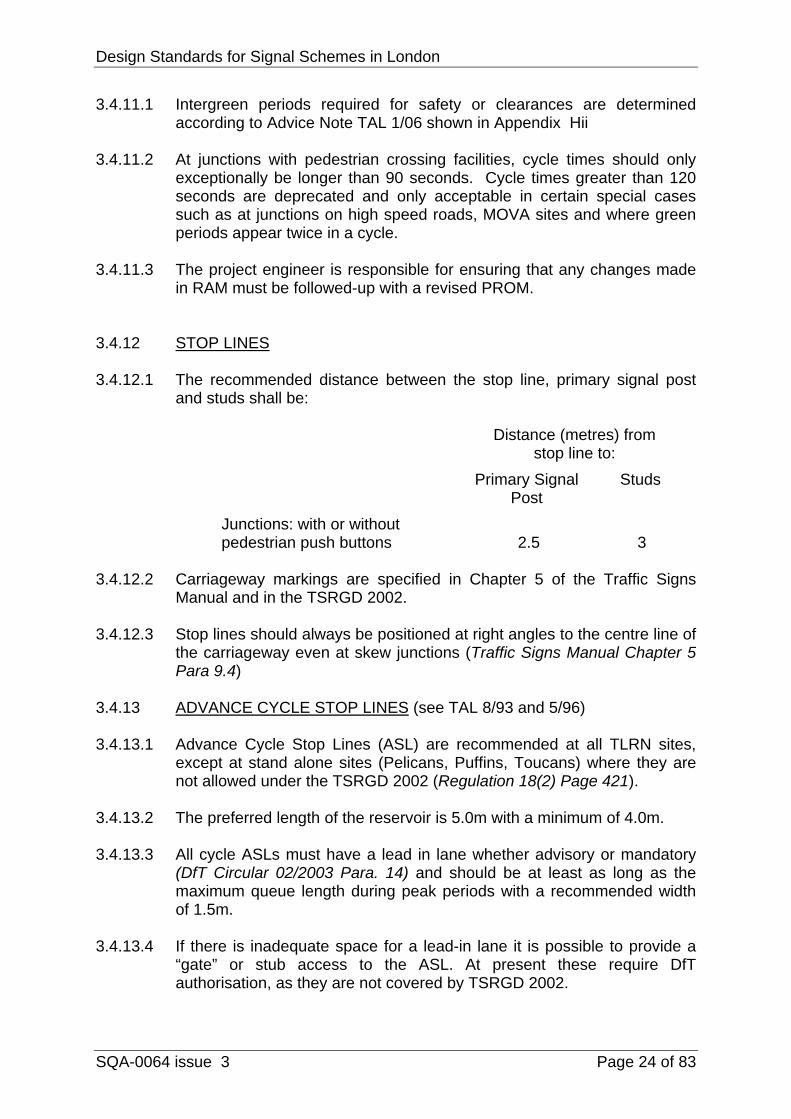
3.4.11.1 Intergreen periods required for safety or clearances are determined according to Advice Note TAL 1/06 shown in Appendix Hii
3.4.11.2 At junctions with pedestrian crossing facilities, cycle times should only
exceptionally be longer than 90 seconds. Cycle times greater than 120 seconds are deprecated and only acceptable in certain special cases such as at junctions on high speed roads, MOVA sites and where green periods appear twice in a cycle.
3.4.11.3 The project engineer is responsible for ensuring that any changes made
in RAM must be followed-up with a revised PROM. 3.4.12 STOP LINES 3.4.12.1 The recommended distance between the stop line, primary signal post
and studs shall be:
Distance (metres) from stop line to: Primary Signal Studs Post Junctions: with or without pedestrian push buttons 2.5 3
3.4.12.2 Carriageway markings are specified in Chapter 5 of the Traffic Signs
Manual and in the TSRGD 2002.
3.4.12.3 Stop lines should always be positioned at right angles to the centre line of the carriageway even at skew junctions (Traffic Signs Manual Chapter 5 Para 9.4)
3.4.13 ADVANCE CYCLE STOP LINES (see TAL 8/93 and 5/96) 3.4.13.1 Advance Cycle Stop Lines (ASL) are recommended at all TLRN sites,
except at stand alone sites (Pelicans, Puffins, Toucans) where they are not allowed under the TSRGD 2002 (Regulation 18(2) Page 421).
3.4.13.2 The preferred length of the reservoir is 5.0m with a minimum of 4.0m.
3.4.13.3 All cycle ASLs must have a lead in lane whether advisory or mandatory
(DfT Circular 02/2003 Para. 14) and should be at least as long as the maximum queue length during peak periods with a recommended width of 1.5m.
3.4.13.4 If there is inadequate space for a lead-in lane it is possible to provide a
“gate” or stub access to the ASL. At present these require DfT authorisation, as they are not covered by TSRGD 2002.

Design Standards for Signal Schemes in London
SQA-0064 issue 3 Page 25 of 83
3.4.13.5 The following factors should be taken into account during the design:
a) the positioning of the cycle lane on the approach to ensure that there is adequate vehicle lane width to accommodate a lead in lane
b) intergreens, which should be calculated from the vehicle stop line
(the one furthest from the signals)
c) an appropriate method of detection for cycles:
d) at existing sites where ASL’s are being installed, it may be necessary to relocate existing stop line detection or replace with overhead detection.
e) when undertaking swept paths, the width of carriageway should be
taken from the outer edge of the cycle feeder lane and not from the kerb edge.
f) when proposing an ASL, designers should take into account the
existence of any red light cameras as the may need to be relocated.
3.4.14 DETECTORS 3.4.14.1 Above ground detectors are to be used in preference to sub surface
loops. The performance of above ground detectors shall comply with DfT Specification TR 2123. The siting of loop detectors shall comply with DfT Specification MCE 0108. In the UTC area detectors (other than for SCOOT) are not provided except on roads with minor flows. These roads must be provided with stop line detection where there is a likelihood that the stage could be skipped through lack of demand for a significant period of the day or night.
3.4.14.2 The following Detector Fault Monitor times should be used as a basis for
specifications:
Detector Type Active Timer Inactive Timer Above-Ground Detectors and inductive loops
30mins 9hrs
Push-button units 30mins 96hrs (196hrs to 255hrs for central
islands)* On-Crossing Detectors 1hr 18hrs
* - The PEEK TSC3 controller has an upper limit of 72hrs for DFM timers.

Design Standards for Signal Schemes in London
SQA-0064 issue 3 Page 26 of 83
3.4.15 DETECTION AND SPEED ASSESSMENT (SA) EQUIPMENT AT
JUNCTIONS (see references TA 12/81, MCE 0108, TR 2123 and TR 2500)
Detection equipment shall be fitted as follows:
3.4.15.1 30 mph roads - new installations 3.4.15.1.1 85 percentile speed less than 35mph
Microwave vehicle detection (MVD) should be used. Only where microwave detection is unsuitable should loop detectors be used.
3.4.15.1.2 85 percentile speed greater than 35mph
MVDs should normally be used unless there are special circumstances based on traffic engineering judgement, which require speed assessment equipment. However consideration should be given to speed reducing measures or changing the speed limit.
Intergreen values should be set at the upper level which would exist if SA was present and a vehicle was detected at a max change.
If however SA is required then a fully ducted feeder cable system should be provided with funding by the client.
3.4.15.1.3 85 percentile speed 45 mph or higher
SA should be provided as well as simple system D. As MVDs will not be used with SA, ducts should be provided for all feeder cables at the client or the highway authority’s expense.
3.4.15.2 Over 30 mph roads irrespective of speed - new installations
As 3.4.15 & 3.4.15.1.3 3.4.15.3 Modernisation of existing installations
The same general rules apply although due to the absence of information on speeds it may not be possible to make an accurate assessment. It may therefore be necessary to obtain speed-readings to confirm the precise requirements. Although it is not envisaged that additional detection facilities such as speed

Design Standards for Signal Schemes in London
SQA-0064 issue 3 Page 27 of 83
assessment will be required at many sites a fully ducted system should be provided when required.
3.4.16 SITING OF CONTROLLERS (see reference TD 50/04) 3.4.16.1 A controller shall be sited so that its position will allow unimpeded use of
the footway by pedestrians, those using wheelchairs or pushing prams. It should allow the outercase door and panels to be opened to their full extent. When the doors are open they should not cause undue obstruction on the footway but there should be sufficient clearance for an operative to work. The controller should not obstruct other street furniture and should not mask waiting pedestrians from approaching vehicles.
3.4.16.2 When the controller is installed on unmade ground a concrete pad or
paving slabs should be provided in front of the outercase doors to assist maintenance.
3.4.16.3 When working at the controller an engineer should preferably be able to
view the junction and the stop-lines. 3.4.16.4 Where controllers are situated in places such as the centres of
roundabouts or gyratories consideration should be given to providing a hard standing area for the maintenance company’s vehicles.
3.4.17 SITING OF ELECTRICITY SUPPLY PILLARS 3.4.17.1 Guidelines for siting a pillar are as follows:
• The supply pillar should usually be a minimum of 5.0m from the signal controller and usually not more than 10m, where there is a risk of the controller being knocked down.
• It should be sited at the back of the footpath close against a wall or fence where generally it will be safe from vehicular collision.
• It must not obstruct private property, doorways, accesses or shop windows.
• It must not obstruct the footway or cause a hazard to pedestrians. • It must not obstruct access, panels or openings to other street
furniture. • It must be positioned so that engineers working on the pillar can do
so without danger to themselves from vehicles • .Feeder Pillars should not be positioned abutting pedestrian guard
railing, as the railing may be removed at a later date, making the Feeder Pillar a trip hazard.
Design Standards for Signal Schemes in London
SQA-0064 issue 3 Page 28 of 83
4 STAND ALONE CROSSINGS
4.1 GENERAL
4.1.1 To assist in the design process, it is recommended that the client should
complete a “Site assessment record sheet” as shown in Appendix D when submitting schemes.
4.1.2 At stand alone crossings, multi-lane approaches are not recommended and where possible should be designed out, if necessary by provision of a central refuge. If that is not possible, tall poles or mast arms may have to be considered.
4.1.3 (TI preferred layouts shown at Appendix E) 4.1.4 All crossings shall be designed according to LTN 2/95. The particular
requirements for a crossing installation in London are given below.
4.2 PUSH BUTTONS, AUDIBLES AND TACTILES 4.2.1 All single crossings should be provided with both audible and tactile
facilities. However if the highway authority do not want audibles fitted, because they are socially unacceptable, they can be arranged to switch off at night by means of a timeswitch, or, providing tactile facilities are in place, they may be omitted.
4.2.2 With far sided signals, pedestrian push buttons should normally be
mounted at an angle of 45˚ to the kerb line.
4.2.3 Where near side signals are used the Pedestrian Display Units (PDU’s) should generally be mounted at an angle of 25-30˚ to the kerb line except at staggered crossings where the guidance in the Puffin Good Practice Guide should be followed. High level repeaters must always be provided.
4.2.4 Where PDU’s are fitted on central refuge islands, the controller must be
configured so that the units on the central island display a Black Out sequence during the extension periods.
4.2.5 Tactile cones should normally only be installed in the right hand push
button when facing the crossing. If there is a central refuge, then two push buttons should be installed on the refuge, both with tactile units. (TAL 5/05 Part 3)
4.2.6 To ensure consistency for visually impaired people the tactile unit should
be installed on the right hand side of the bottom of the push button unit. (Inclusive mobility Para 3.12)
4.3 SIGNAL ASPECTS AND HOODS
Design Standards for Signal Schemes in London
SQA-0064 issue 3 Page 29 of 83
4.3.1 At sites where there are two or more lanes on an approach an offside secondary signal should be included and the offside primary signal aspect should be offset to allow clear visibility of the secondary signal.
4.3.2 Primary hoods should be used on secondary signals at crossings as it
improves the visibility both on the approach and from the stop line.
4.4 BOX SIGNS
4.4.1 For signal-controlled pedestrian facilities (TSRGD Reg 47 (3) (d) (ii)), equestrian crossings (Reg 48 (3) (d) (ii)) and for Toucans (Reg 49 (3) (d) (ii)) the following signs are allowed as box signs:
606 White arrow on blue background (AO, TL, TR) 612 NRT 613 NLT 616 No entry (although not mentioned in Schedule 17 item 6 of
TSRGD 2002)
The following ”exemption” plates may be added:-
954.7 Except buses (may be varied to Except cycles) 954.7 Except buses & cycles (may be varied to local buses or buses &
taxis) 954.8 Except buses, taxis & cycles (may be varied to local buses &
cycles or local buses & taxis)
4.5 SKID RESISTANT SURFACING 4.5.1 At least 50m of skid resistant surfacing shall be provided on the approach
to all crossings, which should be taken up to the first row of studs. On a gradient, or on a road with a speed limit above 30mph, it may be necessary to increase this length.
4.5.2 An installation will not be switched on unless such surfacing has been
provided or in its absence the highway authority has supplied a written statement of indemnity, that confirms that it will be proved within the next 6 months.
Design Standards for Signal Schemes in London
SQA-0064 issue 3 Page 30 of 83
4.6 ROAD MARKINGS
4.6.1 These shall be in accordance with TSRGD 2002, The Zebra, Pelican and
Puffin Pedestrian Crossings Regulations and General Directions 1997 and Chapter 5 of the Traffic Signs Manual.
4.6.2 All forms of stand alone crossings, including ped-x’s must have zig-zag road markings (TSRGD 2002 Dir 49).
4.6.3 The recommended distance between the stop line and studs is 3m and between the stop line and the primary signal post is 2.5m.
4.7 DETECTION 4.7.1 Where vehicle detection is required and speed assessment equipment is
not to be provided above ground detectors are preferred. The performance of above ground detectors shall comply with DfT Specification TR 2123. The siting of loop detectors, when used, shall comply with DfT Specification MCE 0108.
4.7.2 Kerbside call/cancel detectors should ideally not to be used on
installations that have pre-timed max.
4.8 LINKING 4.8.1 Linking may be provided to nearby crossings as site conditions dictate,
e.g. to avoid frustration or congestion. If so, the reason should be recorded in the project file. This link may be in the form of:
• A line share for UTC control; • A leaving/starting amber link; or • Cableless linking (also used to link junctions when the UTC system
is not operating). 4.8.2 Local links and delay timers may be overridden by UTC.
Note: All link cables should be ducted. 4.8.3 Cross Inhibit Linking must be provided at staggered stand alone crossings
except when they are controlled by another controller or stream, as this facility is likely to interfere with the operation of the local linking. Pedestrian progression achieved by a call-ahead facility may be implemented if requested by the client but shall be assessed on an individual site basis. On UTC sites Cross Inhibit Linking will be overridden when under computer control where applicable.
Design Standards for Signal Schemes in London
SQA-0064 issue 3 Page 31 of 83
4.9 TIMINGS
4.9.1 Dual Vehicle Precedence periods shall be provided on all installations
under UTC control. The higher period to be used when the crossing is working isolated, the lower period when under UTC so that the crossing can be double cycled where possible.
4.9.2 Pre-timed max is included as standard on TfL pedestrian controllers, but it
should not be used on roads with a speed limit greater than 30mph.
4.10 VEHICLE DETECTION AND SPEED ASSESSMENT (SA)
These shall be provided as follows: 4.10.1 30 mph roads - New installations 4.10.1.1 85 percentile speed less than 35 mph
No detection. These sites shall operate fixed time. However if, using engineering judgement, some form of vehicle actuation is required or would be beneficial, then MVDs should be used.
No SA required.
4.10.1.2 85 percentile speed between 35 mph and 45 mph
VA detection (c) or (d) in Table 2 of LTN 2/95 and Speed Assessment (SA) are a requirement in this speed range. There is a provision to allow the use of MVDs on high speed roads in Scotland but confirmation of such a provision in London may be required.
If the installation is under UTC control, detection is not provided.
For installations outside the UTC area MVDs should be used to provide vehicle actuation.
The ‘Red Man / Red to Traffic’ (period 3) should be set on its maximum value of 3 seconds.
4.10.1.3 85 percentile speed greater than 45 mph
If the installation is under UTC control, no detection shall be provided but the ‘Red Man / Red to Traffic’ (period 3) should be set on its maximum value of 3 seconds.
Design Standards for Signal Schemes in London
SQA-0064 issue 3 Page 32 of 83
For vehicle actuation SA should be provided as well as simple system D detection. MVDs should not be used.
Ducts should be provided for all feeder cables at the client or highway authority’s expense.
4.10.1.4 Over 30 mph roads - irrespective of 85 percentile speed - New
installations
As 4.10.1.3 4.10.1.5 Modernisation of existing installations
The same general rules should apply although due to the absence of the relevant information on speeds it may not be possible to make an accurate assessment. It may therefore be necessary to obtain speed readings to confirm the precise requirements. Although it is not envisaged that additional detection facilities, i.e. SA, will be required at many sites, a fully ducted system should be provided when required as above.

Design Standards for Signal Schemes in London
SQA-0064 issue 3 Page 33 of 83
5 PELICANS
5.1 GENERAL 5.1.1 Design standards for Pelican crossings are given in LTN 2/95.
5.1.2 The Vehicle Precedence time is currently either fixed at 20 seconds or
given an extension. When VA extensions are applied the minimum period shall be 7 seconds up to a maximum of 20 seconds. There must be good traffic engineering reasons for a longer period, e.g. where there is a very heavy vehicle movement and a continuous light pedestrian demand.
5.1.3 Vehicle Actuated extensions shall be as given in Appendix F. Timing
periods 1, 2 and 3 are given in Appendix F. Timing periods 4, 5, 6 and 7 shall be determined according to the crossing length. A chart to determine these is given in Appendix F.
5.1.4 An ‘overlap’ stage (Flashing Green Man / Red to Traffic) must be
provided. The ‘overlap’ stage should not exceed 2 seconds and this time should be taken from the Flashing Green Man/Flashing Amber stage.
5.1.5 The minimum recommended crossing width is 3.0m.

Design Standards for Signal Schemes in London
SQA-0064 issue 3 Page 34 of 83
6 TOUCANS
6.1 GENERAL 6.1.1 Design standards for Toucan crossings are given in LTN 2/95; advice is
given in TAL 10/93 and 4/98. 6.1.2 Zig-Zags at Toucans are now a requirement as set out in TSRGD 2002.
Some existing Toucans were installed without zig-zags and Highway Authorities had until 1st January 2007 to install them at these sites.
6.1.3 Far sided signals can be used with on-crossing pedestrian / cycle
detection, near sided signals shall be used with on-crossing detection. 6.1.4 For Far sided Toucans timings are shown in Appendix G(ii) 6.1.5 For Near sided Toucans timings are shown in Appendix G(i) (Puffin
sequence timings). The green man invitation is to be measured as detailed in paragraph 3.3.21 and Figure 3.
6.1.6 High Level repeater signals shall be used at near sided Toucans. The
minimum recommended crossing width is 4.0m. 6.1.7 Where possible the preference is to convert far-sided Toucans to near-
sided Toucans.
Design Standards for Signal Schemes in London
SQA-0064 issue 3 Page 35 of 83
7 PUFFINS
7.1 GENERAL 7.1.1 Where Pedestrian crossings are being replaced by Puffin crossings, the
designers should make allowances for the Puffin requirements for:
• Tactile paving • The position of the nearside signal poles to accommodate the nearside
pedestrian indication unit. • The position of detection equipment
7.1.2 Design standards for Puffin crossings are given in LTN 2/95. Further
information is given in TAL 1/01 “Puffin Pedestrian Crossing” and TAL 1/02 “The Installation of Puffin Pedestrian Crossings” and in the TI Puffin Design Guide Document No: U/S000/TS/603 and in the Puffin Good Practice Guide
7.1.3 Near sided signals shall be used together with on-crossing detection. 7.1.4 The minimum recommended crossing width is 3.0m
7.1.5 High Level Repeaters shall be used. 7.1.6 Timings are as shown in Appendix G.
Design Standards for Signal Schemes in London
SQA-0064 issue 3 Page 36 of 83
8 PEDESTRIAN CROSSINGS (PED-X)
8.1 GENERAL 8.1.1 This layout is only to be used if specifically requested by the Highway
Authority.
8.1.2 The layout is as a Pelican, but the traffic light sequence is as a signalised junction.
8.1.3 Far sided signals shall be used. 8.1.4 Timings are as shown in Appendix H (i).
Design Standards for Signal Schemes in London
SQA-0064 issue 3 Page 37 of 83
9 DOCUMENTATION FOR DESIGN FILE
9.1 GENERAL 9.1.1 If a third party has designed the scheme, the designer shall send TI the
following information:
• The design brief • The Stage 1 Design / Safety Check List • Traffic and Pedestrian Count data • Speed Surveys for the 85%tile approach speeds. • A proposed scheme layout drawing to a scale of 1:200 which
includes the method of control and the proposed ducting system. Drawing number GEN/TTS_06/FIG01 is an example of the detail required. This drawing should extend to at least 50m on all approaches.
• The controller specification • The output of the modelling program (refer to modelling guidelines) • Any local link timings • Collision Data
9.1.2 This information will enable TI to carry out a Stage 2 design check of the
scheme drawing and the controller specification. Only when the scheme design has been approved can work start on site. The Stage 3 design check will be carried out by TI at the time of commissioning.
Design Standards for Signal Schemes in London
SQA-0064 issue 3 Page 38 of 83
Design Standards for Signal Schemes in London
SQA-0064 issue 3 Page 39 of 83
Design Standards for Signal Schemes in London
SQA-0064 issue 3 Page 40 of 83

Design Standards for Signal Schemes in London
SQA-0064 issue 3 Page 41 of 83
Design Standards for Signal Schemes in London
SQA-0064 issue 3 Page 42 of 83
APPROXIMATE SIGNAL EQUIPMENT WEIGHTS - BASED ON PEEK ELITE

Design Standards for Signal Schemes in London
SQA-0064 issue 3 Page 43 of 83
Equipment Weight – Kg (approx.)
RAG Aspect (without brackets) 10.5 Pedestrian Aspect (without brackets) 7.0 Green Arrow Aspect – single 3.5 Box Sign Unit 3.5 RAG brackets 2.5 Pedestrian brackets 2.0 4-in-line brackets 3.0 RAG backing-boards (top and bottom) 1.5 Wait Lamp Transformer 1.0 2m Pole 18.7 4m Pole 35.1 4m Formed Pole 39.3 4.85m Pole 42.5 6m Pole 52.6 6m Pole with Base Plate 77.6 800mm D-Bracket 9.7

Design Standards for Signal Schemes in London
SQA-0064 issue 3 Page 44 of 83
APPENDIX A
DRAWING CHECKLIST CHECK THAT THE FOLLOWING ARE INCLUDED AS NECESSARY: 1. North point 2. Pole numbers 3. Ducts & drawpits/polepits (including any associated notes) 4. Feeders from drawpits to poles 5. P.E. cell 6. P.J.L./Haldo Pillar/Electricity Pillar 7. Controller position and type 8. Zig-zag markings & number required. 9. Method of Control (M.O.C.) 10. Phase letters (shown on signals and M.O.C.) 11. Loops (including distances, names and any feeders) 12. Indicate if pedestrian aspects are pole or side-mounted 13. Whether all necessary road markings are included (e.g. stop lines, studs, lane
markings etc.) 14. Whether all necessary signal information is included (e.g. P/B’s, secondaries,
box-signs, filter arrows, etc.) 15. Barrier Rails 16. Amendment notes & new issue letter. 17. Any deletions in correction fluid to be highlighted. 18. All other amendments to be shown in red ink. 19. Title (with site reference number, project number, date, etc) 20. Street names.
Design Standards for Signal Schemes in London
SQA-0064 issue 3 Page 45 of 83
APPENDIX B 1 DATA REQUIREMENTS FOR COMPUTER MODELLING PROGRAMS
1.1 Geometric data 1.1.1 A scale drawing at 1:200 (or 1:500 for preliminary analysis) of the junction
or junctions and/or a 1:1250 (or 1:2500) if a network is under investigation. The junction drawing should show the number of lanes including short flared lanes, bus lanes and cycle lanes, width of lanes, gradient, turning radii and exit widths. Time of day changes to geometry should be shown, such as bus lane operation, parking (controlled and illegal), loading and other kerbside activity (taxi ranks etc.).
1.1.2 The network drawing provides link length details and how they are
interconnected on the network.
1.2 Junction Control Data 1.2.1 Type of junction control, i.e. priority, roundabout, signalled or grade
separated. If signal controlled, then phasing and staging arrangements are required, including full stage and interstage diagrams showing phase delays.
1.3 Traffic Data
1.3.1 A classified (buses, articulated buses, HGV’s, LGV’s, trams, taxis,
motorcycles, pedal cycles and cars) survey covering peak and off peak periods. Additional data covering the weekend (e.g. Saturday mid-day and Sunday PM) is particularly useful for shopping areas or where there is a significant change in traffic demand.
1.3.2 A queue survey before and after each 15 minute traffic survey interval
(number of vehicles at end of green) will permit actual demand to be better assessed.
1.3.3 Number of vehicles using short lanes, gap acceptance figures for give
ways / right turners, number of vehicles turning right in intergreens and other non-standard behaviour.
1.3.4 Pedestrian flows and proposed control. 1.3.5 Bus routes, flows / frequencies.
1.3.6 Measured saturation flows for each traffic lane, if available. 1.3.7 Accident data. 1.3.8 In addition, for LINKED or NETWORK DESIGN:
Design Standards for Signal Schemes in London
SQA-0064 issue 3 Page 46 of 83
1.3.9 Origin and destination survey. 1.3.10 Journey time information for each link and for key routes through the
network. 1.3.11 Further information can be found in Modelling Guidelines – Traffic
Schemes in London Urban Networks which can be found at www.londonstreetworks.net in Library > traffic signals.

Design Standards for Signal Schemes in London
SQA-0064 issue 3 Page 47 of 83
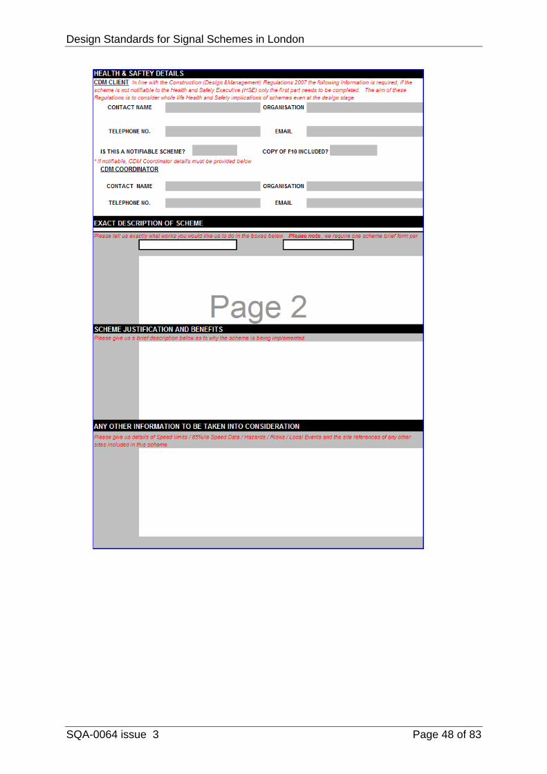
APPENDIX C TfL Traffic Directorate
Design Standards for Signal Schemes in London
SQA-0064 issue 3 Page 48 of 83

Design Standards for Signal Schemes in London
SQA-0064 issue 3 Page 49 of 83
APPENDIX D
STAND ALONE CROSSING – SITE ASSESSMENT RECORD SHEET LOCAL SITE CHARACTERISTICS
1.1 Site Location Description (Attach annotated sketch)
Ordnance Survey Grid Reference
1.2 Carriageway Type Single Double
One-Way Two-Way
Number of lanes
Cycle lanes/tracks
Gradients
1.3 Carriageway Width Metres
1.4 Cycle Lane/Track Width Side 1 Metres
Side 2 Metres
1.5 Footway Width Side 1 Metres
Side 2 Metres
1.6 Useable Verge Width Side 1 Metres
(after carriageway/margin/footway) Side 2 Metres
1.7 Refuge Island Yes / No
Width Metres
1.8 Road Lighting Standard
BS 5489 classification Category
Is the existing lighting in accordance with BS 548 Yes / No
Any rearrangement necessary? Yes / No
Better lighting standard needed? Yes / No
Supplementary lighting needed? Yes / No
Design Standards for Signal Schemes in London
SQA-0064 issue 3 Page 50 of 83
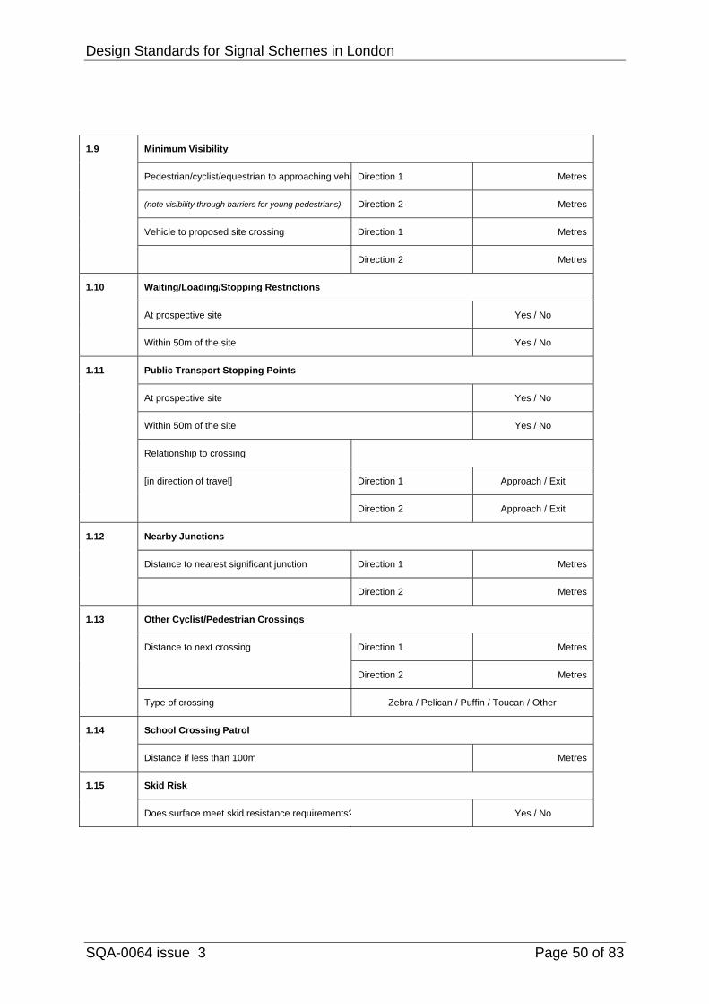
1.9 Minimum Visibility
Pedestrian/cyclist/equestrian to approaching vehi Direction 1 Metres
(note visibility through barriers for young pedestrians) Direction 2 Metres
Vehicle to proposed site crossing Direction 1 Metres
Direction 2 Metres
1.10 Waiting/Loading/Stopping Restrictions
At prospective site Yes / No
Within 50m of the site Yes / No
1.11 Public Transport Stopping Points
At prospective site Yes / No
Within 50m of the site Yes / No
Relationship to crossing
[in direction of travel] Direction 1 Approach / Exit
Direction 2 Approach / Exit
1.12 Nearby Junctions
Distance to nearest significant junction Direction 1 Metres
Direction 2 Metres
1.13 Other Cyclist/Pedestrian Crossings
Distance to next crossing Direction 1 Metres
Direction 2 Metres
Type of crossing Zebra / Pelican / Puffin / Toucan / Other
1.14 School Crossing Patrol
Distance if less than 100m Metres
1.15 Skid Risk
Does surface meet skid resistance requirements? Yes / No
Design Standards for Signal Schemes in London
SQA-0064 issue 3 Page 51 of 83
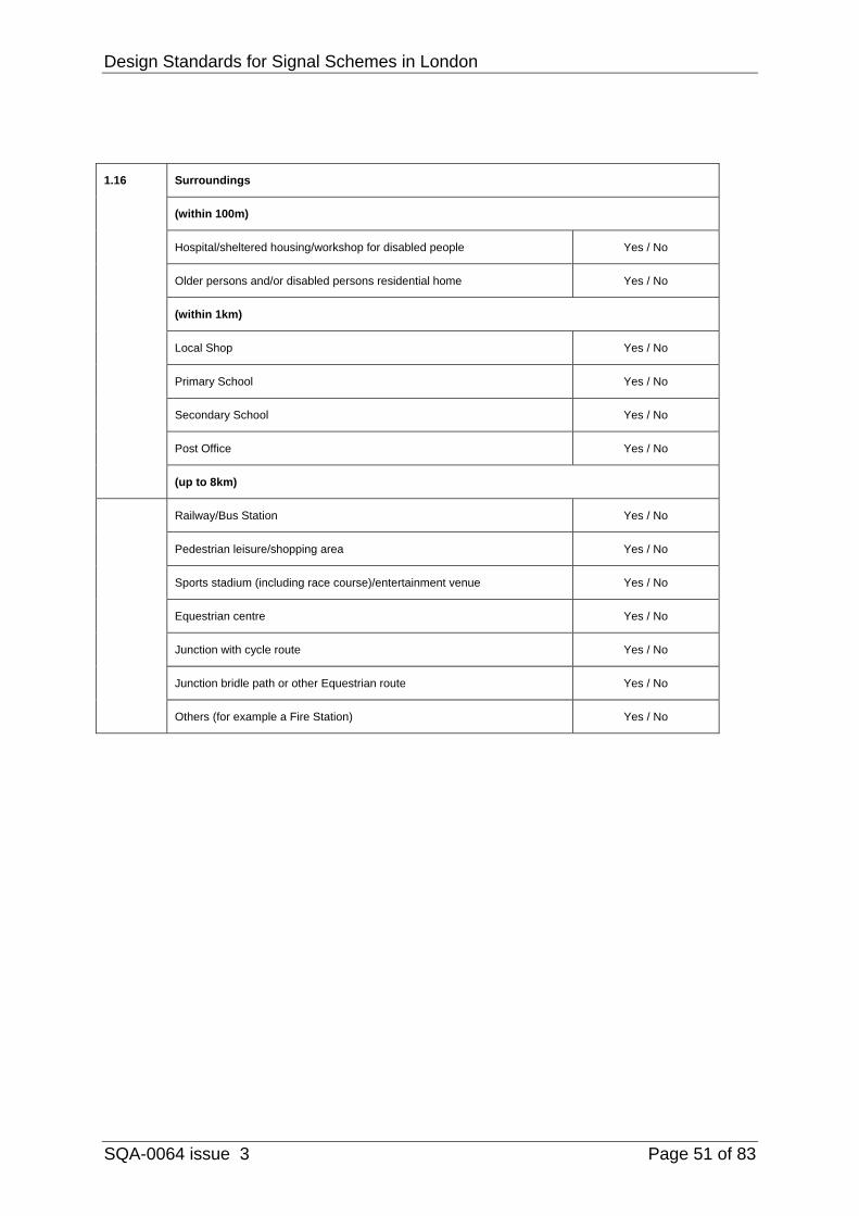
1.16 Surroundings
(within 100m)
Hospital/sheltered housing/workshop for disabled people Yes / No
Older persons and/or disabled persons residential home Yes / No
(within 1km)
Local Shop Yes / No
Primary School Yes / No
Secondary School Yes / No
Post Office Yes / No
(up to 8km)
Railway/Bus Station Yes / No
Pedestrian leisure/shopping area Yes / No
Sports stadium (including race course)/entertainment venue Yes / No
Equestrian centre Yes / No
Junction with cycle route Yes / No
Junction bridle path or other Equestrian route Yes / No
Others (for example a Fire Station) Yes / No
Design Standards for Signal Schemes in London
SQA-0064 issue 3 Page 52 of 83
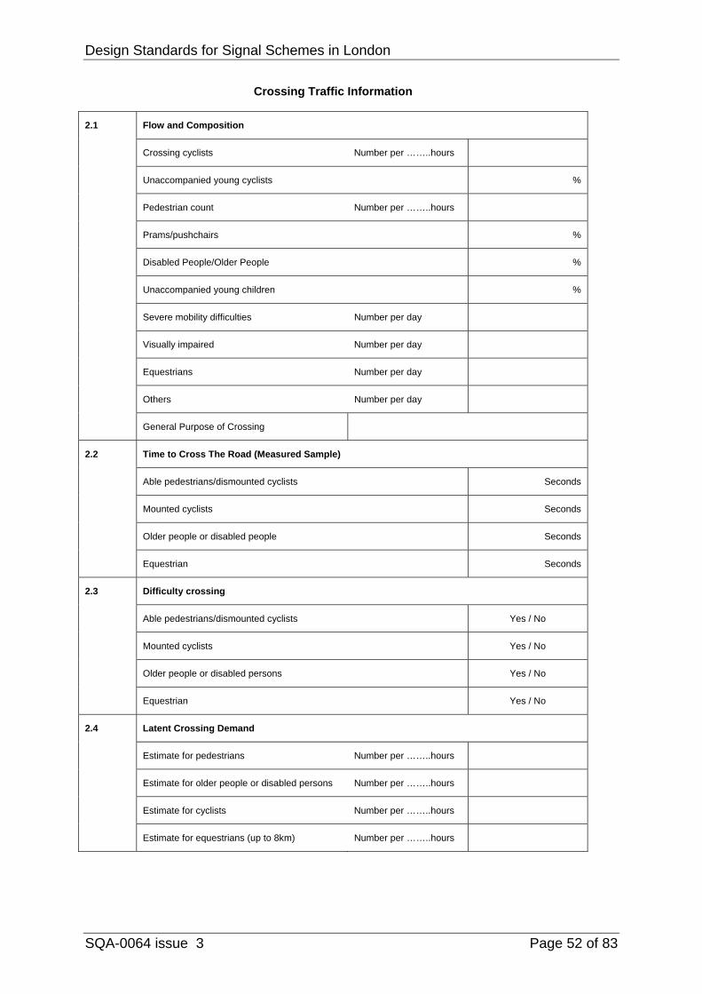
Crossing Traffic Information
2.1 Flow and Composition
Crossing cyclists Number per ……..hours
Unaccompanied young cyclists %
Pedestrian count Number per ……..hours
Prams/pushchairs %
Disabled People/Older People %
Unaccompanied young children %
Severe mobility difficulties Number per day
Visually impaired Number per day
Equestrians Number per day
Others Number per day
General Purpose of Crossing
2.2 Time to Cross The Road (Measured Sample)
Able pedestrians/dismounted cyclists Seconds
Mounted cyclists Seconds
Older people or disabled people Seconds
Equestrian Seconds
2.3 Difficulty crossing
Able pedestrians/dismounted cyclists Yes / No
Mounted cyclists Yes / No
Older people or disabled persons Yes / No
Equestrian Yes / No
2.4 Latent Crossing Demand
Estimate for pedestrians Number per ……..hours
Estimate for older people or disabled persons Number per ……..hours
Estimate for cyclists Number per ……..hours
Estimate for equestrians (up to 8km) Number per ……..hours
Design Standards for Signal Schemes in London
SQA-0064 issue 3 Page 53 of 83
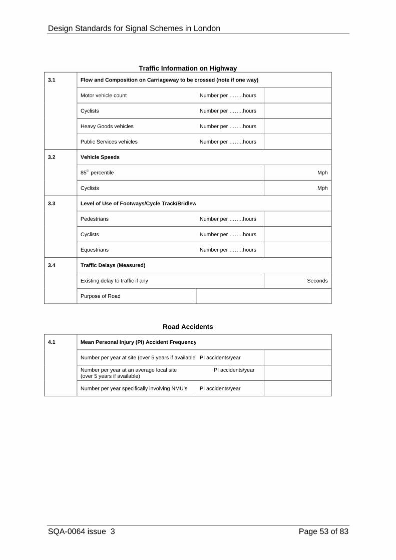
Traffic Information on Highway 3.1 Flow and Composition on Carriageway to be crossed (note if one way)
Motor vehicle count Number per ……..hours
Cyclists Number per ……..hours
Heavy Goods vehicles Number per ……..hours
Public Services vehicles Number per ……..hours
3.2 Vehicle Speeds
85th percentile Mph
Cyclists Mph
3.3 Level of Use of Footways/Cycle Track/Bridlew
Pedestrians Number per ……..hours
Cyclists Number per ……..hours
Equestrians Number per ……..hours
3.4 Traffic Delays (Measured)
Existing delay to traffic if any Seconds
Purpose of Road
Road Accidents
4.1 Mean Personal Injury (PI) Accident Frequency
Number per year at site (over 5 years if available) PI accidents/year
Number per year at an average local site PI accidents/year (over 5 years if available)
Number per year specifically involving NMU’s PI accidents/year
Design Standards for Signal Schemes in London
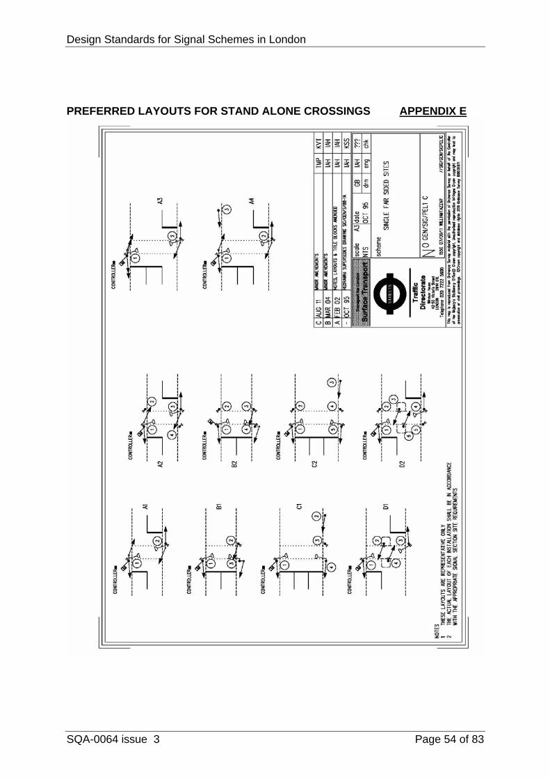
SQA-0064 issue 3 Page 54 of 83
PREFERRED LAYOUTS FOR STAND ALONE CROSSINGS APPENDIX E
Design Standards for Signal Schemes in London
SQA-0064 issue 3 Page 55 of 83
Design Standards for Signal Schemes in London
SQA-0064 issue 3 Page 56 of 83

Design Standards for Signal Schemes in London
SQA-0064 issue 3 Page 57 of 83
APPENDIX F
PELICAN TIMINGS - GREATER LONDON AREA PERIOD TIMINGS Period 1 Red Man - Green 20 seconds (FVP) 20 seconds max, 7 seconds min (VA) ALT Period 1 (where dual VP required) 7 - 20 seconds Period 2 Red Man - Amber 3 seconds - mandatory Period 3 Red Man - Red 2 seconds - gap change 2 seconds - max change 2 second - fixed time 3 seconds - SDE change 2 second - computer change
Design Standards for Signal Schemes in London
SQA-0064 issue 3 Page 58 of 83
VA EXTENSIONS Full and Simple System ‘D’ VA loops
at 12m, 25m & 39m FSL
Minimum extension 1.6 seconds
Single VA loops At 40m FSL Minimum extension 4.0 seconds
(Only to be used at existing sites with this VA loop configuration) MVD Minimum extension 0.2 seconds (Extensions in the range of 0.2
seconds to 0.4 seconds are recommended but this does not preclude the use of a longer extension time if appropriate for site conditions. Note that the MVD internally adds a 0.5 second extension to the output pulse.)
Speed Assessment (SA)
Simple System ‘D’ and a loop at 151m FSL
Extension as provided by controllers to DfT Specification MCE 0125 (Delay Period + 5 seconds)
Design Standards for Signal Schemes in London
SQA-0064 issue 3 Page 59 of 83
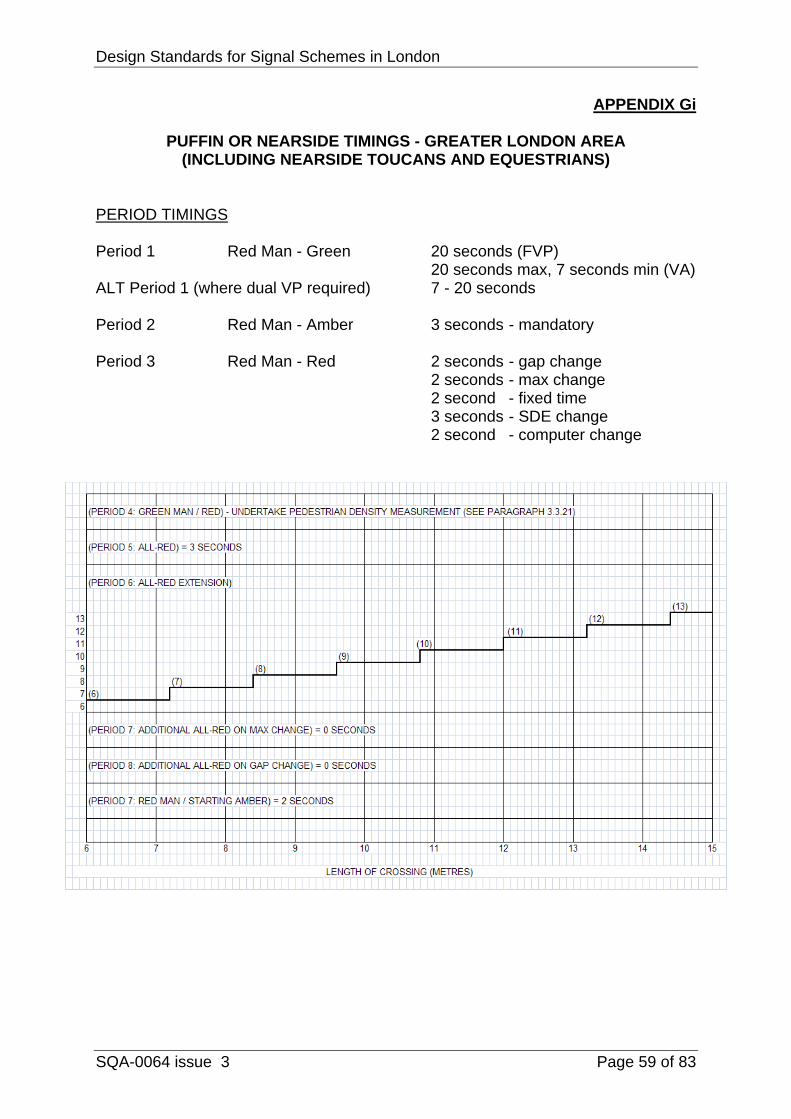
APPENDIX Gi
PUFFIN OR NEARSIDE TIMINGS - GREATER LONDON AREA (INCLUDING NEARSIDE TOUCANS AND EQUESTRIANS)
PERIOD TIMINGS Period 1 Red Man - Green 20 seconds (FVP) 20 seconds max, 7 seconds min (VA) ALT Period 1 (where dual VP required) 7 - 20 seconds Period 2 Red Man - Amber 3 seconds - mandatory Period 3 Red Man - Red 2 seconds - gap change 2 seconds - max change 2 second - fixed time 3 seconds - SDE change 2 second - computer change
Design Standards for Signal Schemes in London
SQA-0064 issue 3 Page 60 of 83
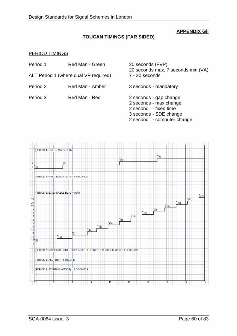
APPENDIX Gii TOUCAN TIMINGS (FAR SIDED)
PERIOD TIMINGS Period 1 Red Man - Green 20 seconds (FVP) 20 seconds max, 7 seconds min (VA) ALT Period 1 (where dual VP required) 7 - 20 seconds Period 2 Red Man - Amber 3 seconds - mandatory Period 3 Red Man - Red 2 seconds - gap change 2 seconds - max change 2 second - fixed time 3 seconds - SDE change 2 second - computer change
Design Standards for Signal Schemes in London
SQA-0064 issue 3 Page 61 of 83
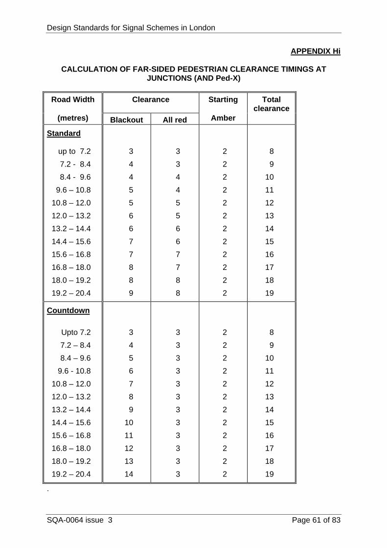
APPENDIX Hi
CALCULATION OF FAR-SIDED PEDESTRIAN CLEARANCE TIMINGS AT JUNCTIONS (AND Ped-X)
Road Width Clearance Starting Total
clearance (metres) Blackout All red Amber
Standard up to 7.2 7.2 - 8.4 8.4 - 9.6 9.6 – 10.8 10.8 – 12.0 12.0 – 13.2 13.2 – 14.4 14.4 – 15.6 15.6 – 16.8 16.8 – 18.0 18.0 – 19.2 19.2 – 20.4
3 4 4 5 5 6 6 7 7 8 8 9
3 3 4 4 5 5 6 6 7 7 8 8
2 2 2 2 2 2 2 2 2 2 2 2
8 9
10 11 12 13 14 15 16 17 18 19
Countdown Upto 7.2 7.2 – 8.4 8.4 – 9.6 9.6 - 10.8 10.8 – 12.0 12.0 – 13.2 13.2 – 14.4 14.4 – 15.6 15.6 – 16.8 16.8 – 18.0 18.0 – 19.2 19.2 – 20.4
3 4 5 6 7 8 9
10 11 12 13 14
3 3 3 3 3 3 3 3 3 3 3 3
2 2 2 2 2 2 2 2 2 2 2 2
8 9
10 11 12 13 14 15 16 17 18 19
.
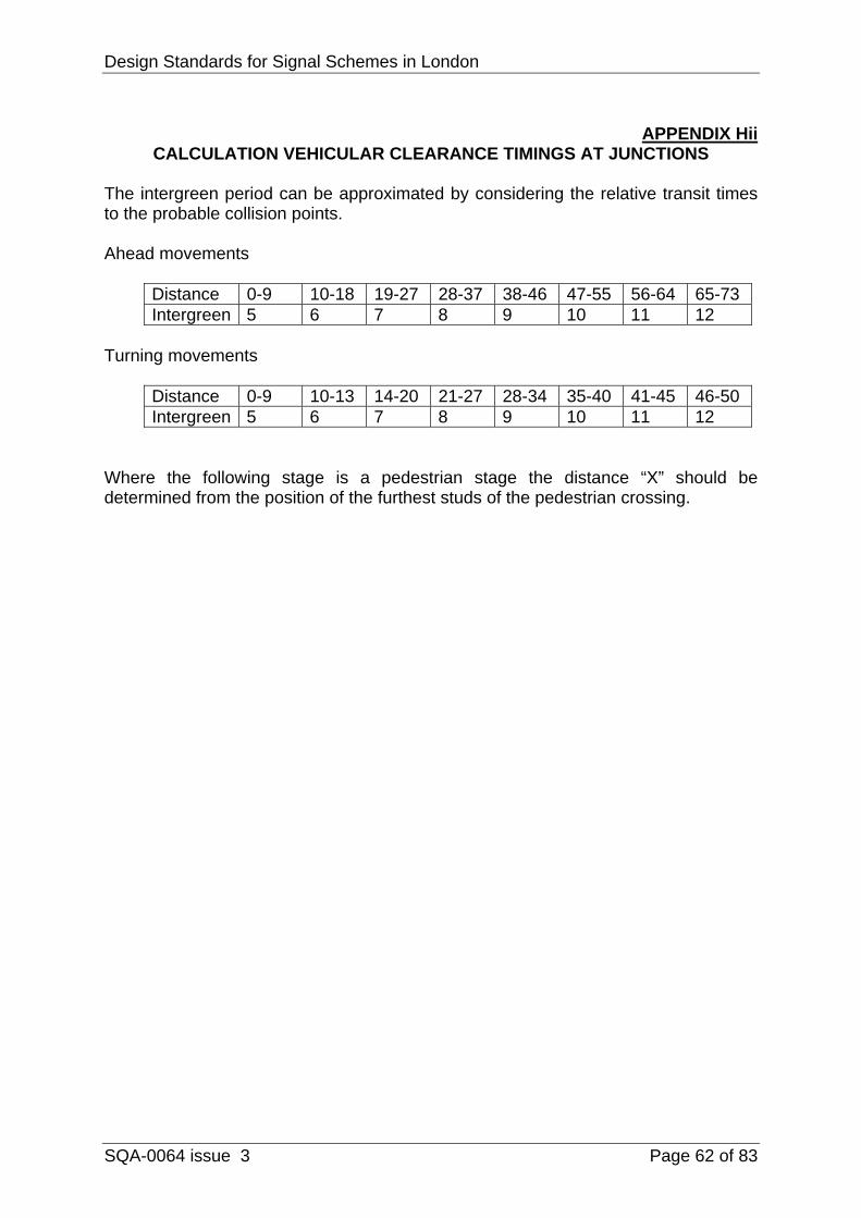
Design Standards for Signal Schemes in London
SQA-0064 issue 3 Page 62 of 83
APPENDIX Hii
CALCULATION VEHICULAR CLEARANCE TIMINGS AT JUNCTIONS The intergreen period can be approximated by considering the relative transit times to the probable collision points. Ahead movements
Distance 0-9 10-18 19-27 28-37 38-46 47-55 56-64 65-73 Intergreen 5 6 7 8 9 10 11 12
Turning movements
Distance 0-9 10-13 14-20 21-27 28-34 35-40 41-45 46-50 Intergreen 5 6 7 8 9 10 11 12
Where the following stage is a pedestrian stage the distance “X” should be determined from the position of the furthest studs of the pedestrian crossing.

Design Standards for Signal Schemes in London
SQA-0064 issue 3 Page 63 of 83
APPENDIX I

Design Standards for Signal Schemes in London
SQA-0064 issue 3 Page 64 of 83

Design Standards for Signal Schemes in London
SQA-0064 issue 3 Page 65 of 83

Design Standards for Signal Schemes in London
SQA-0064 issue 3 Page 66 of 83
APPENDIX J

Design Standards for Signal Schemes in London
SQA-0064 issue 3 Page 67 of 83

Design Standards for Signal Schemes in London
SQA-0064 issue 3 Page 68 of 83

Design Standards for Signal Schemes in London
SQA-0064 issue 3 Page 69 of 83

Design Standards for Signal Schemes in London
SQA-0064 issue 3 Page 70 of 83

Design Standards for Signal Schemes in London
SQA-0064 issue 3 Page 71 of 83
APPENDIX K

Design Standards for Signal Schemes in London
SQA-0064 issue 3 Page 72 of 83

Design Standards for Signal Schemes in London
SQA-0064 issue 3 Page 73 of 83
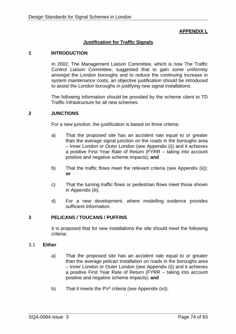
Design Standards for Signal Schemes in London
SQA-0064 issue 3 Page 74 of 83
APPENDIX L
Justification for Traffic Signals 1 INTRODUCTION
In 2002, The Management Liaison Committee, which is now The Traffic Control Liaison Committee, suggested that to gain some uniformity amongst the London boroughs and to reduce the continuing increase in system maintenance costs, an objective justification should be introduced to assist the London boroughs in justifying new signal installations.
The following information should be provided by the scheme client to TD Traffic Infrastructure for all new schemes.
2 JUNCTIONS
For a new junction, the justification is based on three criteria:
a) That the proposed site has an accident rate equal to or greater
than the average signal junction on the roads in the boroughs area – Inner London or Outer London (see Appendix (i)) and it achieves a positive First Year Rate of Return (FYRR – taking into account positive and negative scheme impacts); and
b) That the traffic flows meet the relevant criteria (see Appendix (ii));
or
c) That the turning traffic flows or pedestrian flows meet those shown in Appendix (iii).
d) For a new development, where modelling evidence provides
sufficient information. 3 PELICANS / TOUCANS / PUFFINS
It is proposed that for new installations the site should meet the following criteria:
3.1 Either
a) That the proposed site has an accident rate equal to or greater than the average pelican installation on roads in the boroughs area – Inner London or Outer London (see Appendix (i)) and it achieves a positive First Year Rate of Return (FYRR – taking into account positive and negative scheme impacts); and
b) That it meets the PV² criteria (see Appendix (iv)).
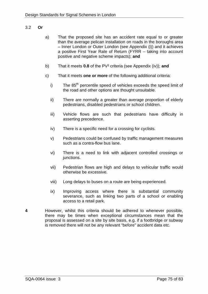
Design Standards for Signal Schemes in London
SQA-0064 issue 3 Page 75 of 83
3.2 Or
a) That the proposed site has an accident rate equal to or greater than the average pelican installation on roads in the boroughs area – Inner London or Outer London (see Appendix (i)) and it achieves a positive First Year Rate of Return (FYRR – taking into account positive and negative scheme impacts); and
b) That it meets 0.8 of the PV² criteria (see Appendix (iv)); and
c) That it meets one or more of the following additional criteria:
i) The 85th percentile speed of vehicles exceeds the speed limit of
the road and other options are thought unsuitable.
ii) There are normally a greater than average proportion of elderly pedestrians, disabled pedestrians or school children.
iii) Vehicle flows are such that pedestrians have difficulty in
asserting precedence.
iv) There is a specific need for a crossing for cyclists.
v) Pedestrians could be confused by traffic management measures such as a contra-flow bus lane.
vi) There is a need to link with adjacent controlled crossings or
junctions.
vii) Pedestrian flows are high and delays to vehicular traffic would otherwise be excessive.
viii) Long delays to buses on a route are being experienced.
ix) Improving access where there is substantial community
severance, such as linking two parts of a school or enabling access to a retail park.
4 However, whilst this criteria should be adhered to whenever possible,
there may be times when exceptional circumstances mean that the proposal is assessed on a site by site basis, e.g. if a footbridge or subway is removed there will not be any relevant “before” accident data etc.
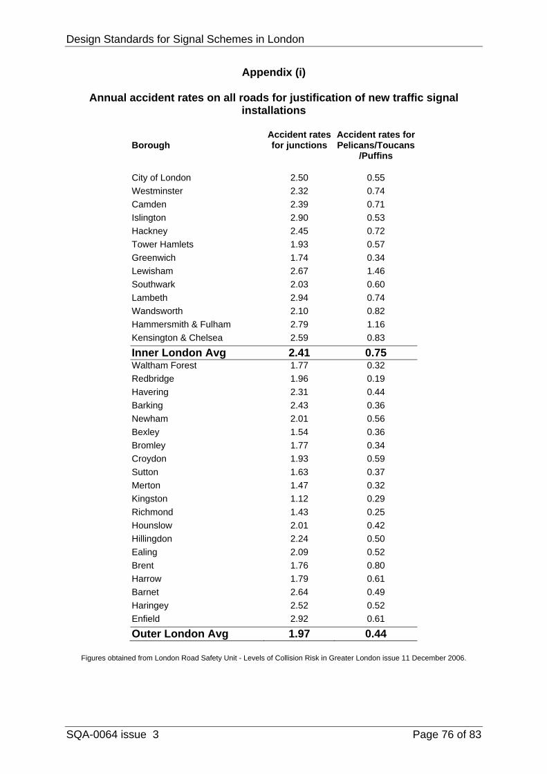
Design Standards for Signal Schemes in London
SQA-0064 issue 3 Page 76 of 83
Appendix (i)
Annual accident rates on all roads for justification of new traffic signal installations
Borough
Accident rates for junctions
Accident rates for Pelicans/Toucans
/Puffins City of London 2.50 0.55Westminster 2.32 0.74Camden 2.39 0.71Islington 2.90 0.53Hackney 2.45 0.72Tower Hamlets 1.93 0.57Greenwich 1.74 0.34Lewisham 2.67 1.46Southwark 2.03 0.60Lambeth 2.94 0.74Wandsworth 2.10 0.82Hammersmith & Fulham 2.79 1.16Kensington & Chelsea 2.59 0.83
Inner London Avg 2.41 0.75 Waltham Forest 1.77 0.32Redbridge 1.96 0.19Havering 2.31 0.44Barking 2.43 0.36Newham 2.01 0.56Bexley 1.54 0.36Bromley 1.77 0.34Croydon 1.93 0.59Sutton 1.63 0.37Merton 1.47 0.32Kingston 1.12 0.29Richmond 1.43 0.25Hounslow 2.01 0.42Hillingdon 2.24 0.50Ealing 2.09 0.52Brent 1.76 0.80Harrow 1.79 0.61Barnet 2.64 0.49Haringey 2.52 0.52Enfield 2.92 0.61
Outer London Avg 1.97 0.44
Figures obtained from London Road Safety Unit - Levels of Collision Risk in Greater London issue 11 December 2006.
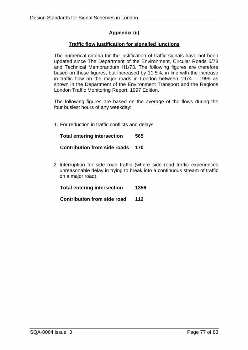
Design Standards for Signal Schemes in London
SQA-0064 issue 3 Page 77 of 83
Appendix (ii)
Traffic flow justification for signalled junctions
The numerical criteria for the justification of traffic signals have not been updated since The Department of the Environment, Circular Roads 5/73 and Technical Memorandum H1/73. The following figures are therefore based on these figures, but increased by 11.5%, in line with the increase in traffic flow on the major roads in London between 1974 – 1995 as shown in the Department of the Environment Transport and the Regions London Traffic Monitoring Report: 1997 Edition.
The following figures are based on the average of the flows during the four busiest hours of any weekday:
1. For reduction in traffic conflicts and delays
Total entering intersection 565
Contribution from side roads 170
2. Interruption for side road traffic (where side road traffic experiences unreasonable delay in trying to break into a continuous stream of traffic on a major road).
Total entering intersection 1356
Contribution from side road 112

Design Standards for Signal Schemes in London
SQA-0064 issue 3 Page 78 of 83
Appendix (iii)
Turning traffic & pedestrian flow justification for signalled junctions
These numerical criteria are based on the figures contained in The Department of the Environment Circular Roads 5/73.
The volume of turning traffic exceeds 700 vph or the flow of pedestrians crossing any arm of the junction is greater than 300 per hour. These figures are to be the average of the flows during the four busiest hours of any day of the week.
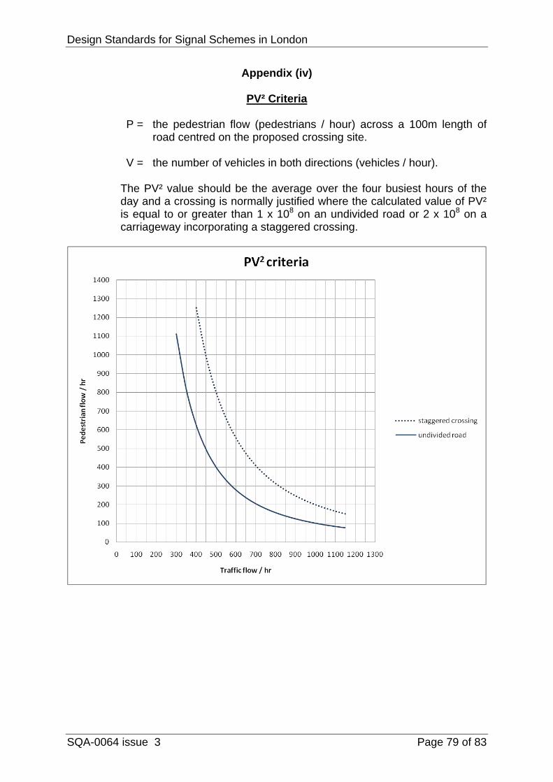
Design Standards for Signal Schemes in London
SQA-0064 issue 3 Page 79 of 83
Appendix (iv)
PV² Criteria
P = the pedestrian flow (pedestrians / hour) across a 100m length of road centred on the proposed crossing site.
V = the number of vehicles in both directions (vehicles / hour).
The PV² value should be the average over the four busiest hours of the day and a crossing is normally justified where the calculated value of PV² is equal to or greater than 1 x 10⁸ on an undivided road or 2 x 10⁸ on a carriageway incorporating a staggered crossing.
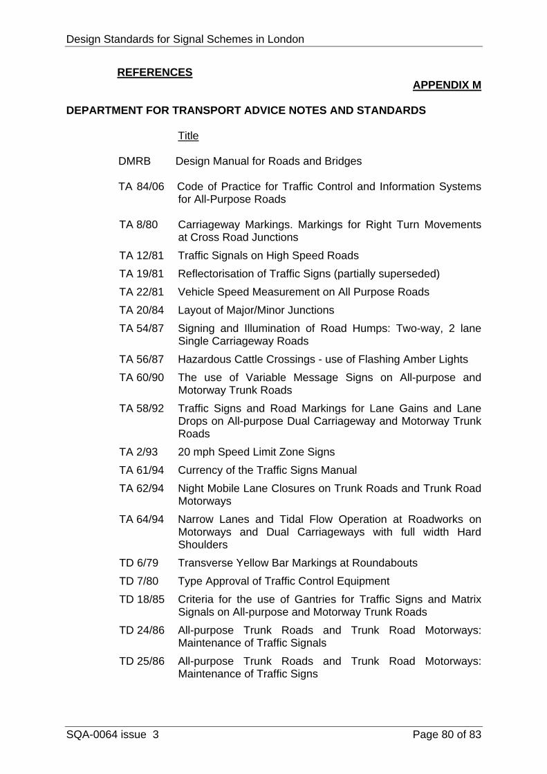
Design Standards for Signal Schemes in London
SQA-0064 issue 3 Page 80 of 83
REFERENCES APPENDIX M
DEPARTMENT FOR TRANSPORT ADVICE NOTES AND STANDARDS
Title
DMRB Design Manual for Roads and Bridges
TA 84/06 Code of Practice for Traffic Control and Information Systems for All-Purpose Roads
TA 8/80 Carriageway Markings. Markings for Right Turn Movements
at Cross Road Junctions TA 12/81 Traffic Signals on High Speed Roads TA 19/81 Reflectorisation of Traffic Signs (partially superseded) TA 22/81 Vehicle Speed Measurement on All Purpose Roads TA 20/84 Layout of Major/Minor Junctions TA 54/87 Signing and Illumination of Road Humps: Two-way, 2 lane
Single Carriageway Roads TA 56/87 Hazardous Cattle Crossings - use of Flashing Amber Lights TA 60/90 The use of Variable Message Signs on All-purpose and
Motorway Trunk Roads TA 58/92 Traffic Signs and Road Markings for Lane Gains and Lane
Drops on All-purpose Dual Carriageway and Motorway Trunk Roads
TA 2/93 20 mph Speed Limit Zone Signs TA 61/94 Currency of the Traffic Signs Manual TA 62/94 Night Mobile Lane Closures on Trunk Roads and Trunk Road
Motorways TA 64/94 Narrow Lanes and Tidal Flow Operation at Roadworks on
Motorways and Dual Carriageways with full width Hard Shoulders
TD 6/79 Transverse Yellow Bar Markings at Roundabouts TD 7/80 Type Approval of Traffic Control Equipment TD 18/85 Criteria for the use of Gantries for Traffic Signs and Matrix
Signals on All-purpose and Motorway Trunk Roads TD 24/86 All-purpose Trunk Roads and Trunk Road Motorways:
Maintenance of Traffic Signals TD 25/86 All-purpose Trunk Roads and Trunk Road Motorways:
Maintenance of Traffic Signs
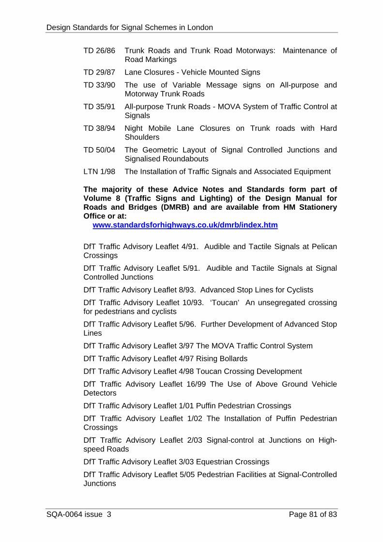
Design Standards for Signal Schemes in London
SQA-0064 issue 3 Page 81 of 83
TD 26/86 Trunk Roads and Trunk Road Motorways: Maintenance of Road Markings
TD 29/87 Lane Closures - Vehicle Mounted Signs TD 33/90 The use of Variable Message signs on All-purpose and
Motorway Trunk Roads TD 35/91 All-purpose Trunk Roads - MOVA System of Traffic Control at
Signals TD 38/94 Night Mobile Lane Closures on Trunk roads with Hard
Shoulders TD 50/04 The Geometric Layout of Signal Controlled Junctions and
Signalised Roundabouts LTN 1/98 The Installation of Traffic Signals and Associated Equipment
The majority of these Advice Notes and Standards form part of Volume 8 (Traffic Signs and Lighting) of the Design Manual for Roads and Bridges (DMRB) and are available from HM Stationery Office or at:
www.standardsforhighways.co.uk/dmrb/index.htm DfT Traffic Advisory Leaflet 4/91. Audible and Tactile Signals at Pelican Crossings DfT Traffic Advisory Leaflet 5/91. Audible and Tactile Signals at Signal Controlled Junctions DfT Traffic Advisory Leaflet 8/93. Advanced Stop Lines for Cyclists DfT Traffic Advisory Leaflet 10/93. ‘Toucan’ An unsegregated crossing for pedestrians and cyclists DfT Traffic Advisory Leaflet 5/96. Further Development of Advanced Stop Lines DfT Traffic Advisory Leaflet 3/97 The MOVA Traffic Control System DfT Traffic Advisory Leaflet 4/97 Rising Bollards DfT Traffic Advisory Leaflet 4/98 Toucan Crossing Development DfT Traffic Advisory Leaflet 16/99 The Use of Above Ground Vehicle Detectors DfT Traffic Advisory Leaflet 1/01 Puffin Pedestrian Crossings DfT Traffic Advisory Leaflet 1/02 The Installation of Puffin Pedestrian Crossings DfT Traffic Advisory Leaflet 2/03 Signal-control at Junctions on High-speed Roads DfT Traffic Advisory Leaflet 3/03 Equestrian Crossings DfT Traffic Advisory Leaflet 5/05 Pedestrian Facilities at Signal-Controlled Junctions
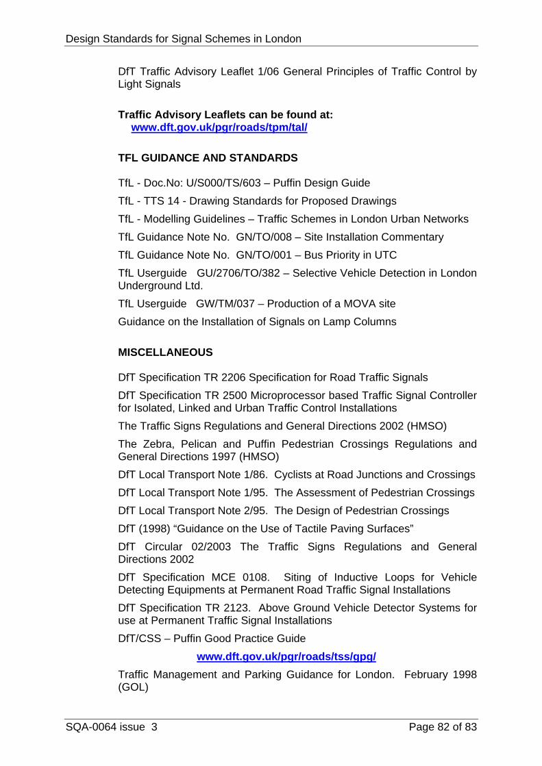
Design Standards for Signal Schemes in London
SQA-0064 issue 3 Page 82 of 83
DfT Traffic Advisory Leaflet 1/06 General Principles of Traffic Control by Light Signals
Traffic Advisory Leaflets can be found at:
www.dft.gov.uk/pgr/roads/tpm/tal/
TFL GUIDANCE AND STANDARDS
TfL - Doc.No: U/S000/TS/603 – Puffin Design Guide TfL - TTS 14 - Drawing Standards for Proposed Drawings TfL - Modelling Guidelines – Traffic Schemes in London Urban Networks TfL Guidance Note No. GN/TO/008 – Site Installation Commentary TfL Guidance Note No. GN/TO/001 – Bus Priority in UTC TfL Userguide GU/2706/TO/382 – Selective Vehicle Detection in London Underground Ltd. TfL Userguide GW/TM/037 – Production of a MOVA site Guidance on the Installation of Signals on Lamp Columns
MISCELLANEOUS
DfT Specification TR 2206 Specification for Road Traffic Signals DfT Specification TR 2500 Microprocessor based Traffic Signal Controller for Isolated, Linked and Urban Traffic Control Installations The Traffic Signs Regulations and General Directions 2002 (HMSO) The Zebra, Pelican and Puffin Pedestrian Crossings Regulations and General Directions 1997 (HMSO) DfT Local Transport Note 1/86. Cyclists at Road Junctions and Crossings DfT Local Transport Note 1/95. The Assessment of Pedestrian Crossings DfT Local Transport Note 2/95. The Design of Pedestrian Crossings DfT (1998) “Guidance on the Use of Tactile Paving Surfaces” DfT Circular 02/2003 The Traffic Signs Regulations and General Directions 2002 DfT Specification MCE 0108. Siting of Inductive Loops for Vehicle Detecting Equipments at Permanent Road Traffic Signal Installations DfT Specification TR 2123. Above Ground Vehicle Detector Systems for use at Permanent Traffic Signal Installations DfT/CSS – Puffin Good Practice Guide www.dft.gov.uk/pgr/roads/tss/gpg/ Traffic Management and Parking Guidance for London. February 1998 (GOL)
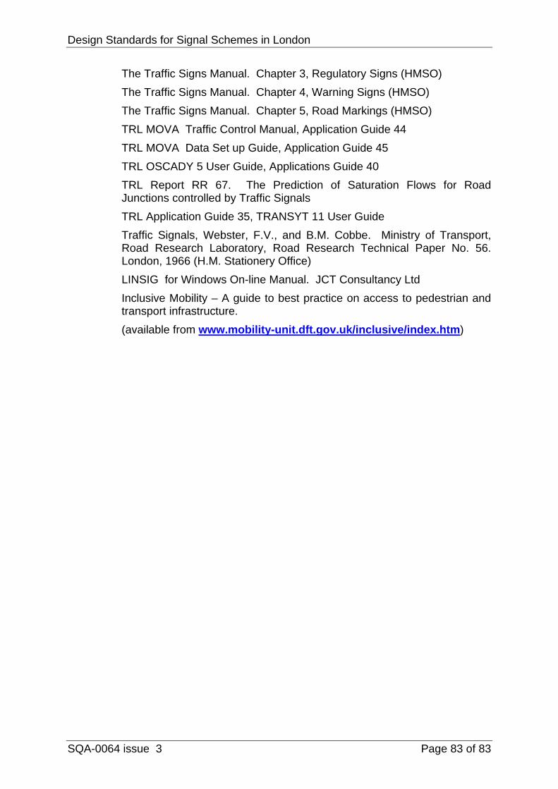
Design Standards for Signal Schemes in London
SQA-0064 issue 3 Page 83 of 83
The Traffic Signs Manual. Chapter 3, Regulatory Signs (HMSO) The Traffic Signs Manual. Chapter 4, Warning Signs (HMSO) The Traffic Signs Manual. Chapter 5, Road Markings (HMSO) TRL MOVA Traffic Control Manual, Application Guide 44 TRL MOVA Data Set up Guide, Application Guide 45 TRL OSCADY 5 User Guide, Applications Guide 40 TRL Report RR 67. The Prediction of Saturation Flows for Road Junctions controlled by Traffic Signals TRL Application Guide 35, TRANSYT 11 User Guide Traffic Signals, Webster, F.V., and B.M. Cobbe. Ministry of Transport, Road Research Laboratory, Road Research Technical Paper No. 56. London, 1966 (H.M. Stationery Office) LINSIG for Windows On-line Manual. JCT Consultancy Ltd Inclusive Mobility – A guide to best practice on access to pedestrian and transport infrastructure. (available from www.mobility-unit.dft.gov.uk/inclusive/index.htm)