tubular links for eccentrically braced frames. i: finite
TRANSCRIPT

Tubular Links for Eccentrically Braced Frames.I: Finite Element Parametric Study
Jeffrey W. Berman1 and Michel Bruneau2
Abstract: This paper describes the development and results of a finite element parametric study of eccentrically braced frame linkshaving hollow rectangular cross sections �i.e., tubular links�. The parametric study involves over 200 combinations of geometries andproperties and is divided into two parts. Part A considers a wide range of compactness ratios and link lengths to determine appropriatecompactness ratio limits such that links with tubular cross sections can achieve desired rotation levels prior to significant strengthdegradation from local buckling. Part B of the study involves models developed with flange compactness ratios, web compactness ratios,and stiffener spacings near the proposed design limits from Part A, and also examines links having webs and flanges with different yieldstresses �i.e., hybrid links�. Results of the parametric study are also used to investigate the adequacy of a method for approximating linkoverstrength. A companion paper describes the experimental verification of the proposed design requirements.
DOI: 10.1061/�ASCE�0733-9445�2008�134:5�692�
CE Database subject headings: Seismic design; Steel structures; Ductility; Rotation; Finite element method; Steel frames; Bracing.
Introduction
Eccentrically braced frames �EBFs�, which rely on yielding of alink beam between braces, have been shown to provide ductilityand energy dissipation under seismic loading �Roeder and Popov1978a,b; Popov and Bertero 1980; Hjelmstad and Popov 1983;1984; Malley and Popov 1984; Kasai and Popov 1986a,b; Riclesand Popov 1989; Engelhardt and Popov 1992, among others�.Guidelines for EBF design with links having wide-flange �WF�cross sections are in the current AISC seismic provisions �AISC2005�. However, the use of WF shapes as link beams necessitatesthat they be braced out-of-plane to prevent lateral torsional buck-ling. This requirement has limited their use in bridge piers wherelateral bracing is difficult to provide.
There have been some applications of EBFs with built-upI-shaped links in bridge piers for long span bridges such as theSan Francisco-Oakland Bay Bridge and the Richmond-San RafaelBridge �Dusicka et al. 2002; Itani 1997�. In these cases, eithervery short links were used or special considerations for link sta-bility were made, which may have increased the cost of theprojects. Therefore, the development of a link type that does notrequire lateral bracing is desirable for application of EBFs inbridge piers. Such self-stabilizing links would also be useful in
1Assistant Professor, Dept. of Civil and Environmental Engineering,More Hall 201-Box 352700, Univ. of Washington, Seattle, WA 98195-2700. E-mail: [email protected]
2Director, Multidisciplinary Center for Earthquake EngineeringResearch, Professor, Dept. of Civil Structural and EnvironmentalEngineering, Univ. at Buffalo, Amherst, NY 14260. E-mail: [email protected]
Note. Associate Editor: Benjamin W. Schafer. Discussion open untilOctober 1, 2008. Separate discussions must be submitted for individualpapers. To extend the closing date by one month, a written request mustbe filed with the ASCE Managing Editor. The manuscript for this paperwas submitted for review and possible publication on June 15, 2006;approved on April 9, 2007. This paper is part of the Journal of Struc-tural Engineering, Vol. 134, No. 5, May 1, 2008. ©ASCE, ISSN 0733-
9445/2008/5-692–701/$25.00.692 / JOURNAL OF STRUCTURAL ENGINEERING © ASCE / MAY 2008
buildings where lateral bracing may not be feasible or easily pro-vided, such as in an elevator core area where floor framing is notpresent. Further, the design of EBFs to protect existing bridge pierbracing members may be employed using the approach in Bermanand Bruneau �2005b�, or EBF systems may be used to replaceexisting deficient pier brace systems.
A proof-of-concept EBF having a link with a tubular crosssection and no lateral bracing has been tested and shown to pos-sess ductility and rotation capacity similar to that of WF links�Berman and Bruneau 2007�. Tubular cross sections, such as thegeneral one shown in Fig. 1, have substantial torsional stability,making them less susceptible to lateral torsional buckling, therebyreducing or eliminating the need for lateral bracing. On thestrength of this successful proof-of-concept test, it is desirable todevelop design recommendations for tubular cross sections em-ployed in this application. Of primary importance is the develop-ment of limit compactness ratios for the webs and flanges as wellas minimum stiffener requirements such that links can achievedesired rotation levels prior to strength degradation from localbuckling. It is also important to characterize the expected over-strength of tubular links with various cross-sectional properties sothat capacity design of surrounding framing may be achieved.Further, as tubular links may be built-up or hybrid cross sectionsconsisting of webs and flanges with differing thicknesses andyield strengths, the proposed compactness ratio limits must beapplicable for a range of yield stresses. Note that built-up sectionsare considered because the longest shear link possible with acommon HSS is 457 mm �Berman and Bruneau 2005a�. This is arather short length and will result in large rotation demands atdesign frame drift levels. Therefore, built-up tubular links arelikely necessary and are the subject of this research.
This paper describes a finite element parametric study, aimedat determining limiting compactness ratios for EBF links havingtubular cross sections, involving over 200 combinations of geom-etries and material properties. First, a finite element model of thelink from proof-of-concept testing in Berman and Bruneau �2007�is briefly discussed as this is the base model for the parametric
study. Following this, the parametric study is presented in two
parts. Part A considers a wide range of compactness ratios andlink lengths to develop proposed design requirements. Part B ofthe study involves models developed with flange compactnessratios, web compactness ratios, and stiffener spacings near theproposed design limits, and also examines links having webs andflanges with different yield stresses �i.e., hybrid links�. Resultsfrom both parts of the study are also used to adapt a link over-strength formulation by Richards �2004� for WF links to linkshaving tubular cross sections. The companion paper, Berman andBruneau �2007b�, describes the experimental verification of theproposed design requirements using 14 different test specimens.
It is important to note that this parametric study parallels asimilar analytical study of the effect of flange width-to-thicknessratio on WF EBF link rotation capacity by Richards and Uang�2005�, which also considered experimental data from Okazakiet al. �2005, 2006�. As discussed herein, similar analytical modelsand failure criteria are chosen for the current study for the pur-pose of maintaining consistency such that implementation of linkswith tubular cross sections may be efficiently achieved.
Finite-Element Modeling of Proof-of-Concept Link
A finite element model of the link from the EBF proof-of-concepttesting reported on in Berman and Bruneau �2007� was developedusing the software package ABAQUS �HKS 2001�. This modelwas developed using four-node reduced integration shell elementsand employed nonlinear material and geometry. The details of thetested link are shown in Figs. 2 and 3 and the link sustained afull-cycle at a maximum rotation of 0.123 rad, over 50% morethan the maximum rotation of 0.08 rad allowed for design ofshear links with WF cross sections.
Fig. 1. Generic tubular cross section with perimeter stiffeners
Fig. 2. Proof-of-concept link details
JOU
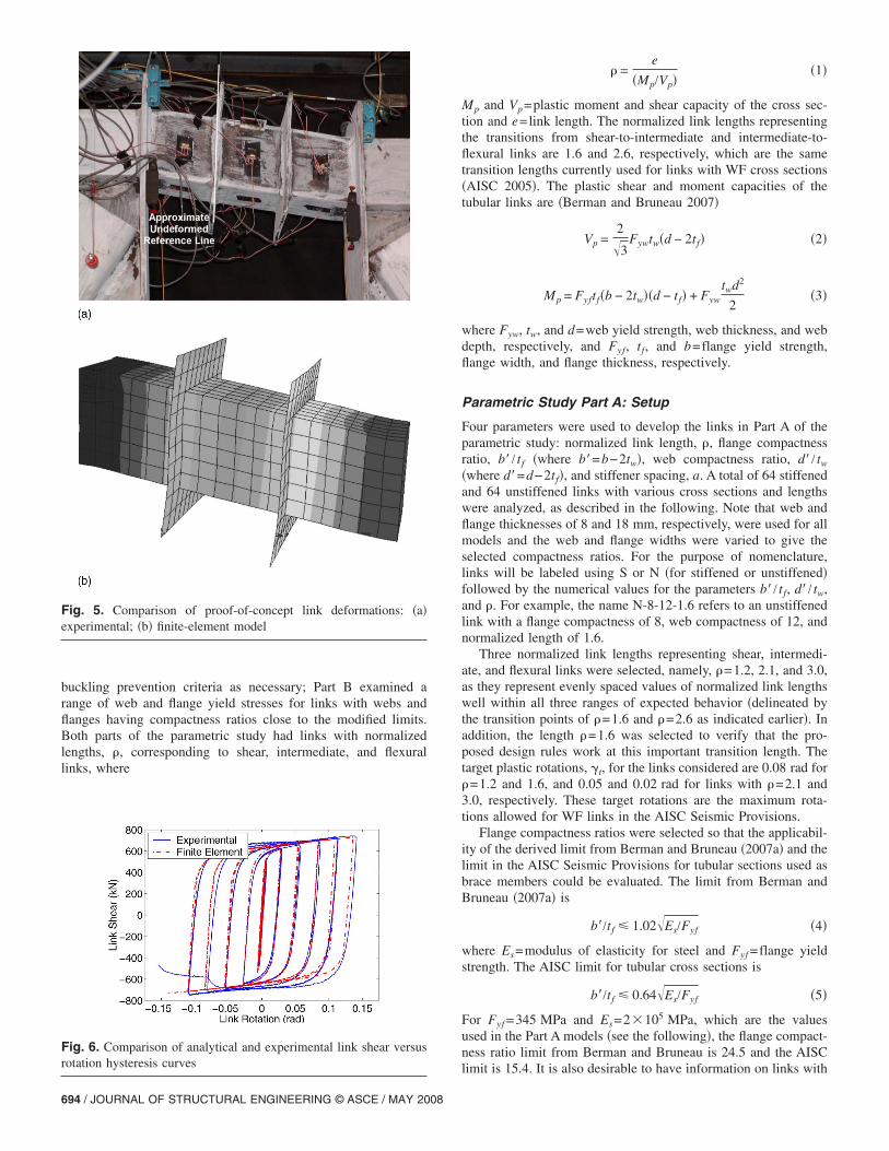
The material model selected had only kinematic hardening,i.e., it neglected the isotropic hardening component which is ac-ceptable for steel at large strains �Berman and Bruneau 2006�, andwas based on cyclic coupon test results of the web and flangematerial. The boundary conditions used are shown in Fig. 4 andwere the same boundary conditions used by Richards and Uang�2005� in their study of WF links. These boundary conditionsensure that equal link end moments are obtained and also preventthe development of link axial force. Loading was applied as avertical displacement at the right end of the link and the rotationhistory from the link of the proof-of-concept test was used, whichcomplied with ATC-24 �ATC 1992�. This loading protocol wasselected for the proof-of-concept test because system behavior,rather than just link behavior, was being explored. The ATC-24protocol is based on a system yield displacement as opposed to alink rotation and therefore seemed to be the appropriate protocolfor this test. A mesh refinement study was performed to determinethe adequate mesh density for the finite elements. A comparisonof the simulated and experimentally obtained link deformedshapes are shown in Fig. 5 for the final mesh, which had elementwidth-to-thickness ratios in the range of 1.6–3.5. Comparing thelink shear force versus rotation hysteresis curves in Fig. 6 showsreasonable agreement with the experimental results. Note that re-sidual stresses were not considered in the modeling, although theyshould only effect the initial yielding.
Finite-Element Parametric Study
Using the finite element model of the link from the proof-of-concept test as a basis, a parametric study of tubular links wasperformed. The parametric study consisted of two parts: Part Ainvestigated links with a wide range of web and flange compact-ness ratios to assess the adequacy of the derived flange compact-ness ratio limit and stiffener spacing equation from Berman andBruneau �2007�, and the results are used to modify those local
Fig. 3. Proof-of-concept link cross sections
Fig. 4. Finite-element model boundary conditions
RNAL OF STRUCTURAL ENGINEERING © ASCE / MAY 2008 / 693
buckling prevention criteria as necessary; Part B examined arange of web and flange yield stresses for links with webs andflanges having compactness ratios close to the modified limits.Both parts of the parametric study had links with normalizedlengths, �, corresponding to shear, intermediate, and flexurallinks, where
Fig. 5. Comparison of proof-of-concept link deformations: �a�experimental; �b� finite-element model
Fig. 6. Comparison of analytical and experimental link shear versusrotation hysteresis curves
694 / JOURNAL OF STRUCTURAL ENGINEERING © ASCE / MAY 2008
� =e
�Mp/Vp��1�
Mp and Vp=plastic moment and shear capacity of the cross sec-tion and e=link length. The normalized link lengths representingthe transitions from shear-to-intermediate and intermediate-to-flexural links are 1.6 and 2.6, respectively, which are the sametransition lengths currently used for links with WF cross sections�AISC 2005�. The plastic shear and moment capacities of thetubular links are �Berman and Bruneau 2007�
Vp =2�3
Fywtw�d − 2tf� �2�
Mp = Fyftf�b − 2tw��d − tf� + Fyw
twd2
2�3�
where Fyw, tw, and d=web yield strength, web thickness, and webdepth, respectively, and Fyf, tf, and b=flange yield strength,flange width, and flange thickness, respectively.
Parametric Study Part A: Setup
Four parameters were used to develop the links in Part A of theparametric study: normalized link length, �, flange compactnessratio, b� / tf �where b�=b−2tw�, web compactness ratio, d� / tw
�where d�=d−2tf�, and stiffener spacing, a. A total of 64 stiffenedand 64 unstiffened links with various cross sections and lengthswere analyzed, as described in the following. Note that web andflange thicknesses of 8 and 18 mm, respectively, were used for allmodels and the web and flange widths were varied to give theselected compactness ratios. For the purpose of nomenclature,links will be labeled using S or N �for stiffened or unstiffened�followed by the numerical values for the parameters b� / tf, d� / tw,and �. For example, the name N-8-12-1.6 refers to an unstiffenedlink with a flange compactness of 8, web compactness of 12, andnormalized length of 1.6.
Three normalized link lengths representing shear, intermedi-ate, and flexural links were selected, namely, �=1.2, 2.1, and 3.0,as they represent evenly spaced values of normalized link lengthswell within all three ranges of expected behavior �delineated bythe transition points of �=1.6 and �=2.6 as indicated earlier�. Inaddition, the length �=1.6 was selected to verify that the pro-posed design rules work at this important transition length. Thetarget plastic rotations, �t, for the links considered are 0.08 rad for�=1.2 and 1.6, and 0.05 and 0.02 rad for links with �=2.1 and3.0, respectively. These target rotations are the maximum rota-tions allowed for WF links in the AISC Seismic Provisions.
Flange compactness ratios were selected so that the applicabil-ity of the derived limit from Berman and Bruneau �2007a� and thelimit in the AISC Seismic Provisions for tubular sections used asbrace members could be evaluated. The limit from Berman andBruneau �2007a� is
b�/tf � 1.02�Es/Fyf �4�
where Es=modulus of elasticity for steel and Fyf =flange yieldstrength. The AISC limit for tubular cross sections is
b�/tf � 0.64�Es/Fyf �5�
For Fyf =345 MPa and Es=2�105 MPa, which are the valuesused in the Part A models �see the following�, the flange compact-ness ratio limit from Berman and Bruneau is 24.5 and the AISC
limit is 15.4. It is also desirable to have information on links with
relatively stocky and slender flanges to examine the effect of linkoverstrength and the general effect of flange compactness on linkbehavior. Therefore, flange compactness ratios of 8.0, 17.0, 24.0,and 40.0 were selected, the first being well below both limits, thesecond near the AISC limit, the third near the derived limit, andthe fourth well above both limits.
Limits for webs of HSS shapes in the AISC seismic provisionsare the same as those for the flanges, i.e., d� / tw�0.64�Es /Fyw.However, this limit was found for HSS sections in compression,and larger compactness ratios may be possible here as the linkwebs yield in shear and may have stiffeners. Therefore, webscompactness ratios below and well above that limit were selectedand both stiffened and unstiffened cases were considered. Theweb compactness ratios selected were 12.0, 16.0, 24.0, and 36.0.For links with stiffeners, the stiffener spacing was selected tosatisfy the equation for tubular links as derived in Berman andBruneau �2007�
a
tw+
1
8
d
tw= CB �a � d� �6�
where CB=20 and 37 for ultimate link rotations of 0.08 and0.02 rad, respectively. Note that for a web compactness ratio of36, the required stiffener spacing, a, found from the proposedstiffener spacing equation is 0.43 times the web depth d, which isnear a practical lower bound on stiffener spacing. When roundingof the stiffener spacing obtained from Eq. �6� was necessary toconform with the element mesh, it was done such that the spacingat the link ends was always greater than the result from Eq. �6� toensure conservative results. Stiffener widths and thicknesses wereselected according to the requirements derived in Berman andBruneau �2007�.
As mentioned earlier, all link models in Part A of the paramet-ric study had web and flange thicknesses of 8 and 16 mm, respec-tively. Using these thicknesses, the above-discussed compactnessratios, and nominal yield stresses and modulii of elasticity forboth the webs and flanges of 345 MPa and 2�105 MPa, respec-tively, the link cross-section dimensions given in Table 1 werecalculated. The resulting cross-section aspect ratios, b /d,are shown in Table 2. Note that all link models had elementwidth-to-thickness ratios comparable to that used for the finalmesh refinement of the proof-of-concept link model as shown inTable 1.
Two differences between the link models of the parametricstudy and the model of the proof-of-concept link were used,
Table 1. Cross-Section Dimensions for Part A Links
b� / tf 8.0 17.0 24.0 40.0
b� �mm� 127 270 381 635
b �mm� 143 286 397 651
No. elements 5 11 15 25
El. elements 5 11 15 25
El. edge-to-thicknessa 1.6 1.5 1.6 1.6
d� / tw 12.0 16.0 24.0 36.0
d� �mm� 95 127 191 286
d �mm� 127 159 222 318
No. elements 4 6 8 12
El. edge-to-thicknessa 3.0 2.7 3.0 3.0aThe mesh refinement study during proof-of-concept link modelingindicated values between 1.6 and 3.2 gave acceptable results �Bermanand Bruneau 2007�.
namely, the input data for the material model and the loading
JOU
history. The material data used as input for the kinematic harden-ing material model for the links of Part A of the finite elementparametric study are shown as the solid true stress versus truestrain curve in Fig. 7. These data differ from that used in themodel of the proof-of-concept link, which was based on coupontest results for that link’s steel. The data used in the parametricstudy are based on cyclic coupon test results for A572 Grade 50steel from Kaufmann et al. �2001�. The loading history used forthe parametric study links was that given for link testing in the2002 AISC Seismic Design Provisions for Steel Buildings �AISC2002�, which specifies three cycles at each total link rotation levelof 0.0025, 0.005, and 0.01 rad, followed by two cycles at 0.01 radincrements up to the maximum code specified rotation. However,for the current research purposes, loading was continued with twocycles at 0.01 rad increments up to 0.2 rad of total rotation orconvergence failure due to very large buckling displacements,whichever happened first. Note that a revision to this loadingprotocol now appears in the 2005 AISC Seismic Design Provi-sions for Steel Buildings �AISC 2005� and it has been shown thatthe older loading is more severe and therefore conservative �Oka-zaki et al. 2005; Richards and Uang 2006; Berman and Bruneau2008�.
For the purpose of this parametric study, the limit plastic ro-tation, �lim, is defined as the inelastic rotation at which the back-bone curve of the link shear force hysteresis drops below 80% ofthe maximum link shear force obtained for a given link. Thisdefinition is selected because it represents a negligible degrada-tion so that a bilinear approximation may be used in practice andit is also consistent with what has been done for WF links. Theprocedure used here to determine the limit rotation is similar to
Table 2. b /d Ratios for Part A Link
Fig. 7. True stress versus true strain curves for finite elementparametric study
RNAL OF STRUCTURAL ENGINEERING © ASCE / MAY 2008 / 695

that used by Richards and Uang �2005� in their study of over-strength and rotation capacity of WF links and can be describedas follows.
First, the normalized link shear force versus plastic rotationhysteresis curve was calculated using MATLAB �Math Works1999� and the results from ABAQUS. For each link, the initialstiffness, kli, was determined by fitting a line through the firstthree points of the link shear versus total rotation hysteresis curve.The plastic rotation at any point in the load history, �p, is thendetermined from
�p = �t = −Vl
kli�7�
where �t=total rotation and Vl=link shear. The shear force, Vl, isthen normalized by the maximum link shear, Vl max, obtained foreach link.
From the normalized link shear versus plastic rotation hyster-esis, the backbone curve is constructed and a simple search algo-rithm is used to find the limit plastic rotation, �p lim, where thelink shear force drops below 80% of the maximum. This limit isselected because it has been used in other similar studies regard-ing plastic rotation capacity since its recommendation in SAC�1997�. An example is shown in Fig. 8 for an unstiffened link withflange and web compactness ratios of 24 and a normalized link
Table 3. Limit Plastic Rotations for Part A Links �rad�
b� / tf d� / tw
Unstiffened
�=1.2 �=1.6 �=2.1
8.0 12.0 0.193 0.176 0.107
8.0 16.0 0.195 0.195 0.104
8.0 24.0 0.086 0.072 0.097
8.0 36.0 0.036 0.036 0.046
17.0 12.0 0.178 0.083 0.049
17.0 16.0 0.158 0.078 0.049
17.0 24.0 0.065 0.064 0.044
17.0 36.0 0.033 0.027 0.035
24.0 12.0 0.122 0.050 0.040
24.0 16.0 0.123 0.051 0.030
24.0 24.0 0.058 0.049 0.033
24.0 36.0 0.026 0.032 0.024
40.0 12.0 0.067 0.026 0.033
40.0 16.0 0.060 0.030 0.017
40.0 24.0 0.063 0.033 0.023
40.0 36.0 0.032 0.024 0.013
Fig. 8. Example of limit plastic rotation determination.
696 / JOURNAL OF STRUCTURAL ENGINEERING © ASCE / MAY 2008
length of 2.1, for which the limit plastic rotation was found to be0.0325 rad. Note that in the companion paper, Berman and Bru-neau �2008�, only one of the links tested suffered severe localbuckling and corresponding strength degradation prior to fractureas shown in Fig. 8. Therefore, severe local buckling in the ana-lytical models has only been verified for that single data point, forwhich the analytically obtained hysteresis shape, energy dissipa-tion, and limit plastic rotation are shown to agree favorably withexperimental results �Berman and Bruneau 2008�. Further, thestudy by Richards and Uang �2005� used similar shell elementmodels of WF links and their results were shown to agree favor-ably with test results from Okazaki et al. �2005�.
Parametric Study Part A: Results
The limit plastic rotation obtained for the link analyses in Part Aof the parametric study are given in Table 3. Recall that no at-tempt to model fracture was made and therefore some of the linksthat have large limit plastic rotations might, in practice, fractureprior to reaching those plastic rotations. For example, the proof-of-concept specimen fractured at a total rotation of 0.15 rad yetthe finite element results for that specimen would indicate that aplastic rotation greater than 0.2 rad could be achieved prior tostrength degradation from buckling.
Several observations can be made regarding the effect of stiff-eners and web compactness on a link’s ability to reach the targetrotation by plotting the data from Table 3 as a function of nor-malized link length for links with b� / tf �17.0 and grouping re-sults in terms of d� / tw values, as shown in Figs. 9�a and b�. Forreference, these figures also have a solid line indicating the AISCspecified maximum rotation �also referred to as the target rota-tion�. First, it appears that links with d� / tw�16.0 and b� / tf
�17.0 can achieve their target rotation without stiffeners. Theseare shown as the squares �d� / tw=12.0� and circles �d� / tw=16.0�of Fig. 9�a�. It was shown by Berman and Bruneau �2005a� thatthe theoretical stiffener spacing equation, for which Eq. �6� is aconvenient approximation, indicates that no stiffeners would berequired for webs with compactness ratios of less than 17.0 �thecurrent AISC compactness limit is 15.4 for rectangular HSS with
Stiffened
�=3.0 �=1.2 �=1.6 �=2.1 �=3.0
0.132 0.193 0.154 0.105 0.132
0.114 0.194 0.174 0.103 0.113
0.084 0.195 0.195 0.095 0.084
0.055 0.196 0.136 0.076 0.055
0.048 0.182 0.081 0.050 0.048
0.040 0.184 0.083 0.048 0.040
0.032 0.194 0.083 0.044 0.032
0.024 0.195 0.085 0.035 0.024
0.044 0.117 0.059 0.043 0.036
0.028 0.119 0.071 0.035 0.028
0.027 0.154 0.056 0.034 0.027
0.021 0.194 0.064 0.024 0.020
0.019 0.092 0.044 0.022 0.020
0.028 0.107 0.047 0.033 0.030
0.019 0.100 0.044 0.020 0.019
0.011 0.118 0.054 0.023 0.013
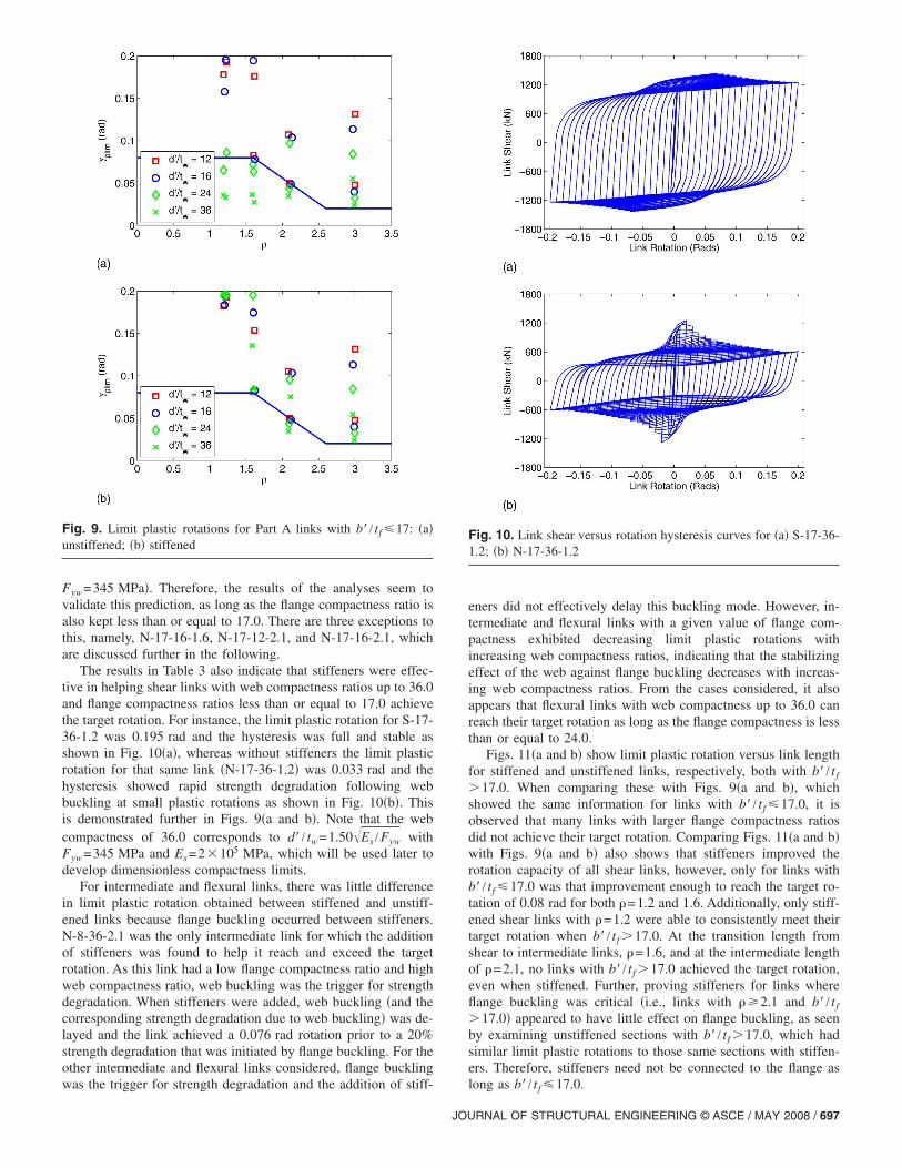
Fyw=345 MPa�. Therefore, the results of the analyses seem tovalidate this prediction, as long as the flange compactness ratio isalso kept less than or equal to 17.0. There are three exceptions tothis, namely, N-17-16-1.6, N-17-12-2.1, and N-17-16-2.1, whichare discussed further in the following.
The results in Table 3 also indicate that stiffeners were effec-tive in helping shear links with web compactness ratios up to 36.0and flange compactness ratios less than or equal to 17.0 achievethe target rotation. For instance, the limit plastic rotation for S-17-36-1.2 was 0.195 rad and the hysteresis was full and stable asshown in Fig. 10�a�, whereas without stiffeners the limit plasticrotation for that same link �N-17-36-1.2� was 0.033 rad and thehysteresis showed rapid strength degradation following webbuckling at small plastic rotations as shown in Fig. 10�b�. Thisis demonstrated further in Figs. 9�a and b�. Note that the webcompactness of 36.0 corresponds to d� / tw=1.50�Es /Fyw withFyw=345 MPa and Es=2�105 MPa, which will be used later todevelop dimensionless compactness limits.
For intermediate and flexural links, there was little differencein limit plastic rotation obtained between stiffened and unstiff-ened links because flange buckling occurred between stiffeners.N-8-36-2.1 was the only intermediate link for which the additionof stiffeners was found to help it reach and exceed the targetrotation. As this link had a low flange compactness ratio and highweb compactness ratio, web buckling was the trigger for strengthdegradation. When stiffeners were added, web buckling �and thecorresponding strength degradation due to web buckling� was de-layed and the link achieved a 0.076 rad rotation prior to a 20%strength degradation that was initiated by flange buckling. For theother intermediate and flexural links considered, flange buckling
Fig. 9. Limit plastic rotations for Part A links with b� / tf �17: �a�unstiffened; �b� stiffened
was the trigger for strength degradation and the addition of stiff-
JOU
eners did not effectively delay this buckling mode. However, in-termediate and flexural links with a given value of flange com-pactness exhibited decreasing limit plastic rotations withincreasing web compactness ratios, indicating that the stabilizingeffect of the web against flange buckling decreases with increas-ing web compactness ratios. From the cases considered, it alsoappears that flexural links with web compactness up to 36.0 canreach their target rotation as long as the flange compactness is lessthan or equal to 24.0.
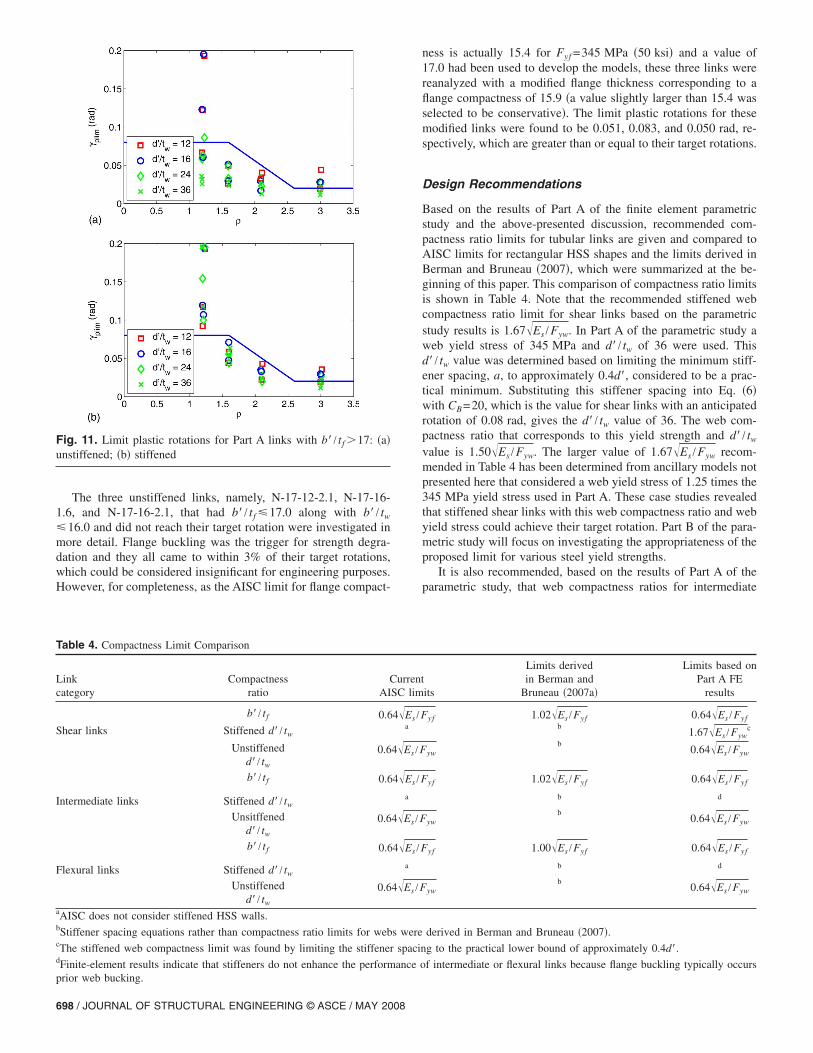
Figs. 11�a and b� show limit plastic rotation versus link lengthfor stiffened and unstiffened links, respectively, both with b� / tf
�17.0. When comparing these with Figs. 9�a and b�, whichshowed the same information for links with b� / tf �17.0, it isobserved that many links with larger flange compactness ratiosdid not achieve their target rotation. Comparing Figs. 11�a and b�with Figs. 9�a and b� also shows that stiffeners improved therotation capacity of all shear links, however, only for links withb� / tf �17.0 was that improvement enough to reach the target ro-tation of 0.08 rad for both �=1.2 and 1.6. Additionally, only stiff-ened shear links with �=1.2 were able to consistently meet theirtarget rotation when b� / tf �17.0. At the transition length fromshear to intermediate links, �=1.6, and at the intermediate lengthof �=2.1, no links with b� / tf �17.0 achieved the target rotation,even when stiffened. Further, proving stiffeners for links whereflange buckling was critical �i.e., links with ��2.1 and b� / tf
�17.0� appeared to have little effect on flange buckling, as seenby examining unstiffened sections with b� / tf �17.0, which hadsimilar limit plastic rotations to those same sections with stiffen-ers. Therefore, stiffeners need not be connected to the flange as
Fig. 10. Link shear versus rotation hysteresis curves for �a� S-17-36-1.2; �b� N-17-36-1.2
long as b� / tf �17.0.
RNAL OF STRUCTURAL ENGINEERING © ASCE / MAY 2008 / 697
The three unstiffened links, namely, N-17-12-2.1, N-17-16-1.6, and N-17-16-2.1, that had b� / tf �17.0 along with b� / tw
�16.0 and did not reach their target rotation were investigated inmore detail. Flange buckling was the trigger for strength degra-dation and they all came to within 3% of their target rotations,which could be considered insignificant for engineering purposes.However, for completeness, as the AISC limit for flange compact-
Table 4. Compactness Limit Comparison
Linkcategory
Compactnessratio
CAI
b� / tf 0.6
Shear links Stiffened d� / tw
Unstiffenedd� / tw
0.6
b� / tf 0.6
Intermediate links Stiffened d� / tw
Unsitffenedd� / tw
0.6
b� / tf 0.6
Flexural links Stiffened d� / tw
Unstiffenedd� / tw
0.6
aAISC does not consider stiffened HSS walls.bStiffener spacing equations rather than compactness ratio limits for webcThe stiffened web compactness limit was found by limiting the stiffenerdFinite-element results indicate that stiffeners do not enhance the perform
Fig. 11. Limit plastic rotations for Part A links with b� / tf �17: �a�unstiffened; �b� stiffened
prior web bucking.
698 / JOURNAL OF STRUCTURAL ENGINEERING © ASCE / MAY 2008
ness is actually 15.4 for Fyf =345 MPa �50 ksi� and a value of17.0 had been used to develop the models, these three links werereanalyzed with a modified flange thickness corresponding to aflange compactness of 15.9 �a value slightly larger than 15.4 wasselected to be conservative�. The limit plastic rotations for thesemodified links were found to be 0.051, 0.083, and 0.050 rad, re-spectively, which are greater than or equal to their target rotations.
Design Recommendations
Based on the results of Part A of the finite element parametricstudy and the above-presented discussion, recommended com-pactness ratio limits for tubular links are given and compared toAISC limits for rectangular HSS shapes and the limits derived inBerman and Bruneau �2007�, which were summarized at the be-ginning of this paper. This comparison of compactness ratio limitsis shown in Table 4. Note that the recommended stiffened webcompactness ratio limit for shear links based on the parametricstudy results is 1.67�Es /Fyw. In Part A of the parametric study aweb yield stress of 345 MPa and d� / tw of 36 were used. Thisd� / tw value was determined based on limiting the minimum stiff-ener spacing, a, to approximately 0.4d�, considered to be a prac-tical minimum. Substituting this stiffener spacing into Eq. �6�with CB=20, which is the value for shear links with an anticipatedrotation of 0.08 rad, gives the d� / tw value of 36. The web com-pactness ratio that corresponds to this yield strength and d� / tw
value is 1.50�Es /Fyw. The larger value of 1.67�Es /Fyw recom-mended in Table 4 has been determined from ancillary models notpresented here that considered a web yield stress of 1.25 times the345 MPa yield stress used in Part A. These case studies revealedthat stiffened shear links with this web compactness ratio and webyield stress could achieve their target rotation. Part B of the para-metric study will focus on investigating the appropriateness of theproposed limit for various steel yield strengths.
It is also recommended, based on the results of Part A of theparametric study, that web compactness ratios for intermediate
its
Limits derivedin Berman and
Bruneau �2007a�
Limits based onPart A FE
results
yf 1.02�Es /Fyf 0.64�Es /Fyfb
1.67�Es /Fywc
ywb
0.64�Es /Fyw
yf 1.02�Es /Fyf 0.64�Es /Fyf
b d
ywb
0.64�Es /Fyw
yf 1.00�Es /Fyf 0.64�Es /Fyf
b d
ywb
0.64�Es /Fyw
derived in Berman and Bruneau �2007�.
g to the practical lower bound of approximately 0.4d�.
f intermediate or flexural links because flange buckling typically occurs
urrentSC lim
4�Es /Fa
4�Es /F
4�Es /F
a
4�Es /F
4�Es /F
a
4�Es /F
s were
spacin
ance o

and flexural links be limited to that for unstiffened shear links.This results from the observation that stiffeners do not enhancethe performance of intermediate or flexural links because flangebuckling typically occurs prior web buckling. Stiffeners in thesecases only change the wavelength of flange buckling, which hasonly a slight impact on the limit rotation. The stiffener spacingequation was found to be adequate and remains unchanged fromthat derived in Berman and Bruneau �2007� and given in Eq. �6�,although it is only recommended for shear links with web com-pactness values between 0.64�Es /Fyw and 1.67�Es /Fyw.
It was also observed in Part A of the study that all flexurallinks with flange compactness ratios less than or equal to 24.0, forany of the four web compactness ratios considered, achieved theirtarget rotation. As a result, the limit flange compactness ratio forflexural links could be increased to 1.00�Es /Fyf. However, forsimplicity, and because they are not commonly used, the com-pactness ratio requirements for flexural links are recommended tobe the same as those for shear and intermediate links, namely,0.64�Es /Fyf. Further, it appears that stiffening the flange has noconsequential effect on the maximum rotation capacity of linkswhere flange buckling controls, so web only stiffeners where re-quired are adequate. Finally, as mentioned earlier, it may be pos-sible to allow larger flange compactness ratios for shear andintermediate links if the limit plastic rotation was made a functionof both the link length and flange compactness ratio. The corre-sponding recommended rotation limits if one considered usingsuch an with increased complexity are presented by Berman andBruneau �2006�. These are not included in the proposed designrequirements here for simplicity and to keep the proposed require-ments for rectangular links similar to the current requirements forWF links.
Parametric Study Part B: Setup
As tubular links may be fabricated with four plates welded to-gether, hybrid cross sections where the yield stresses of the websand flanges are different could be used advantageously. Further,the increased use of low yield point and high performance steelsindicates a practical need for verifying the revised design require-ments for a range of possible yield stresses. Part B of the finiteelement parametric study will therefore investigate tubular linkswith cross-sectional properties near the revised limits of Table 4while also incorporating different yield stresses for both the websand flanges.
Three yield stresses are considered for this part of the study,namely, 250 MPa �36 ksi�, 345 MPa �50 ksi�, and 450 MPa�65 ksi� as these are representative of some of the steels currentlyavailable. True stress versus true strain curves for the materialmodels are shown in Fig. 7. The same normalized link lengthsused in Part A of the study were used in Part B �i.e., � values of1.2, 1.6, 2.1, and 3.0�. Link web and flange compactness ratios forPart B of the parametric study were within 1% of the revisedlimits from Table 4. All links had flange compactness ratios near0.64�Es /Fyf and links with web compactness ratios near both0.64�Es /Fyw and 1.67�Es /Fyw were considered. Links with thelarger we compactness ratio were stiffened according to Eq. �6�.For completeness, intermediate and flexural links with the largerweb compactness ratio were developed, although these are out-side the proposed design requirements. All combinations of pa-rameters �i.e., 4 normalized lengths, 3 web yield stresses, 3 flangeyield stresses, and 2 web compactness ratios� were considered,
resulting in 72 links in Part B of the parametric study.JOU
Parametric Study Part B: Results
Figs. 12�a and b� show limit plastic rotation versus link length forunstiffened links �those with web compactness near 0.64�Es /Fyw�and stiffened links �those with web compactness near1.67�Es /Fyw�, respectively, both grouped by web yield stress.
As shown in Figs. 12�a and b� all unstiffened links �i.e., thosewith web compactness near 0.64�Es /Fyw� reached their target ro-tations, and all stiffened links, except some at the intermediatelength of 2.1, reached their target rotations. The links that did notreach their target rotation in Fig. 12�b� are intermediate links thatdo not satisfy the proposed design requirements. These links wereincluded for comparison purposes, and have the stiffened webswith a compactness ratio near 1.67�Es /Fyw, which is only al-lowed for shear links. Therefore, as all Part B links that satisfiedthe proposed design requirements met their target rotations, theserequirements appear to be satisfactory for the range of web andflange yield strengths considered.
Overstrength of Tubular Links
Determination of the maximum shear force a link can deliver isnecessary to ensure capacity design of surrounding framing. Ri-chards �2004� observed that as WF links get shorter the flangesbegin to share some of the applied shear. This results in ultimateshear strengths exceeding what would be expected consideringonly strain hardening. Therefore, they derived a method for ap-proximating the ultimate shear strength of WF links that depends
Fig. 12. Limit plastic rotations for Part B links �a� unstiffened withlower web compactness ratio; �b� stiffened with larger webcompactness ratio
on the web plastic shear, the shear resisted by the flanges, and the
RNAL OF STRUCTURAL ENGINEERING © ASCE / MAY 2008 / 699

normalized link length. In Berman and Bruneau �2005a�, thatmethod was modified to be applicable to links with tubular crosssections.
Richards �2004� presented the ultimate link shear strength inthe form:
Vult = �RyVpt �8�
where Vpt=total plastic shear force �considering the flange shearas appropriate�; �=cyclic hardening factor defined in the follow-ing; and Ry =ratio of mean to nominal material yield stress asgiven in AISC Seismic Provisions. The shear carried by theflanges of a tubular link, Vf, can be found from �Berman andBruneau 2005a�
Vf =Fybtf
2
2e−
Fytw2 e
8b�9�
and the total plastic shear force, Vpt, is
Vpt = 0.6Fywtw�d − 2tf� + 2Vf �10�
Note that Eq. �9� assumes that the webs and flanges have the sameyield strength, Fy, and that if the web and flange yield strengthsdo differ, an average value may be used.
Richards then suggests that the cyclic hardening parameter, �,should vary with link length as
� = 1.44, � � 1.6
� = 1.44 − 0.4�� − 1.6�, 1.6 � � � 2.6
� = 2.7/�, � � 2.6 �11�
where the 2.7 value in the last expression in Eq. �11� is found byassuming that the maximum moment that can develop is 1.35Mp
�less than the 1.44 used for shear links due to flange bucklinglimiting the strength of flexural links and the fact that stiffenersdo not prevent this failure mode� and employing the link shear-moment relationship for flexural links �V=2Mp /e�.
Figs. 13�a and b� show the ultimate link shear obtained in thefinite element analyses of Part A links normalized by Vull as de-fined earlier, versus normalized link length for unstiffened andstiffened links, respectively. The solid line in Figs. 13�a and b�indicates the curve for the cyclic hardening factor as given by Eq.�11� multiplied by an Ry value of 1.1 �appropriate for the A572Grade 50 steel considered here�. It appears that the overstrengthequations proposed by Richards �2004� for WF links and modi-fied in Berman and Bruneau �2005a� for application to tubularlinks, adequately estimates the ultimate link shear force �fromwhich the maximum link end moment may be found�. Similaragreement with the results from Part B of the parametric studywas observed �Berman and Bruneau 2006�. This procedure seemsto provide a more uniform level of safety relative to a singlevalued overstrength factor, in terms of capacity protection ofstructural members outside the link, for all link lengths and yield-ing types. The points at small normalized link lengths that areabove this proposed overstrength may suffer flange fracture priorto reaching the large overstrengths obtained from the finite ele-ment analyses, but further investigation of this is necessary beforefurther changes are considered to address these extremes. Over-strength will be experimentally investigated in the companionpaper �Berman and Bruneau 2008� to assess whether the resultspredicted here for the cyclic hardening factor applicable to rect-
angular links are appropriate.700 / JOURNAL OF STRUCTURAL ENGINEERING © ASCE / MAY 2008
Conclusions
A finite element parametric study consisting of over 200 modelsof EBF links with tubular cross sections has been conducted. Thestudy investigated a wide range of link geometries and properties,including web and flange compactness ratios, the presence of webstiffeners, link length, and web and flange yield strength. Resultsof the parametric study lead to the following recommendationsfor compactness ratio limits for tubular cross sections used aslinks in EBFs, which are also shown graphically in a design spacein Fig. 14:• All tubular links should have b� / tf �0.64�Es /Fyf;• Shear links ���1.6� should have d� / tw�1.67�Es /Fyw and
those with d� / tw�0.64�Es /Fyw should have stiffeners withspacing, a, satisfying Eq. �6�; and
• Intermediate and flexural links ���1.6� should have d� / tw
�0.64�Es /Fyw.Analysis results indicate that if these compactness ratio recom-mendations are satisfied, tubular links will be able to achieve themaximum rotation levels in the AISC Seismic Provisions for linkswith WF cross sections. This conclusion was also verified byanalyses for tubular links with webs and flanges having differentyield strengths, in the range of 250–450 MPa. Additionally, aprocedure for determining the ultimate strength of tubular links,based on a similar procedure derived by others for WF links, wasshown to reasonably approximate the overstrength of the tubularlinks considered in the analyses. A companion paper, Berman andBruneau �2008�, describes the results of an experimental program
Fig. 13. Link overstrength for Part A links: �a� unstiffened links; �b�stiffened links
to verify the above-presented design recommendations. Addi-

tional information on both the analytical and experimental workcan be found in Berman and Bruneau �2006�.
Acknowledgments
This research was conducted by the State University of New Yorkat Buffalo and was supported by the Federal Highway Adminis-tration under Contract No. DTFH61-98-C-00094 the Multidisci-plinary Center for Earthquake Engineering Research. However,any opinions, findings, conclusions, and recommendations pre-sented in this paper are those of the writers and do not necessarilyreflect the views of the sponsors.
References
AISC. �2002�. Seismic provisions for structural steel buildings, Chicago.AISC. �2005�. Seismic provisions for structural steel buildings, Chicago.Applied Technology Council �ATC�. �1992�. “Guidelines for seismic test-
ing of components of steel structures.” Rep. No. 24, Redwood City,Calif.
Berman, J. W., and Bruneau, M. �2005a�. “Approaches for the seismicretrofit of braced steel bridge piers and proof-of-concept testing of alaterally stable eccentrically braced frame.” Technical Rep. No.MCEER-05-0004, Multidisciplinary Center for Earthquake Engineer-ing Research, Buffalo, N.Y.
Berman, J. W., and Bruneau, M. �2005b�. “Supplemental system retrofitconsiderations for braced steel bridge piers.” J. Earthquake Eng.,34�4,5�, 497–517.
Berman, J. W., and Bruneau, M. �2006�. “Further development of tubulareccentrically braced frame links for the seismic retrofit of braced steeltruss bridge piers.” Technical Rep. No. MCEER-06-0006, Multidisci-plinary Center for Earthquake Engineering Research, Buffalo, N.Y.
Berman, J. W., and Bruneau, M. �2007�. “Experimental and analyticalinvestigation of tubular links for eccentrically braced frames.” Eng.Struct., 29�8�, 1929–1938.
Berman, J. W., and Bruneau, M. �2008�. “Tubular links for eccentricallybraced frames. II: Experimental verification.” J. Struct. Eng., 134�5�,
Fig. 14. Proposed design space for web and flange compactnessratios versus normalized link length
702–712.
JOU
Dusicka, P., Itani, A. M., and Buckle, I. G. �2002�. “Cyclic behavior ofshear links and tower shaft assembly of San Francisco-Oakland BayBridge Tower.” Technical Rep. No. CCEER 02-06, Center for CivilEngineering Earthquake Research, Univ. of Nevada, Reno, Reno,Nev.
Engelhardt, M. D., and Popov, E. P. �1992�. “Experimental performanceof long links in eccentrically braced frames.” J. Struct. Eng., 118�11�,3067–3088.
Hibbitt, Karlsson, and Sorensen, Inc. �HKS�. �2001�. ABAQUS standarduser’s manual, Pawtucket, R.I.
Hjelmstad, K. D., and Popov, E. P. �1983�. “Cyclic behavior and designof link beams.” J. Struct. Eng., 109�10�, 2387–2403.
Hjelmstad, K. D., and Popov, E. P. �1984�. “Characteristics of eccentri-cally braced frames.” J. Struct. Eng., 110�2�, 340–353.
Itani, A. M. �1997�. “Cyclic behavior of Richmond-San Rafael Towerlinks.” Technical Rep. No. CCEER 97-4, Center for Civil EngineeringEarthquake Research, Univ. of Nevada, Reno, Nev.
Kasai, K., and Popov, E. P. �1986a�. “General behavior of WF steel shearlink beams.” J. Struct. Eng., 112�2�, 362–382.
Kasai, K., and Popov, E. P. �1986b�. “Study of seismically resistant ec-centrically braced steel frame systems.” Rep. No. UCB/EERC-86/01,Earthquake Engineering Research Center, College of Engineering,Univ. of California, Berkeley, Calif.
Kaufmann, E. J., Metrovich, B., and Pense, A. W. �2001�. “Characteriza-tion of cyclic inelastic strain behavior on properties of A572 Gr.50and A913 Gr. 50 rolled sections.” ATLSS Rep. No. 01-13, NationalCenter for Engineering Research on Advanced Technology for LargeStructural Systems, Lehigh Univ., Bethlehem, Pa.
Malley, J. O., and Popov, E. P. �1984�. “Shear links in eccentricallybraced frames.” J. Struct. Eng., 110�9�, 2275–2295.
MathWorks. �1999�. MatLab function reference, Natick, Mass.Okazaki, T., Arce, G., Ryu, H. C., and Engelhardt, M. D. �2005�. “Ex-
perimental study of local buckling, overstrength, and fracture of linksin eccentrically braced frames.” J. Struct. Eng., 131�10�, 1526–1535.
Okazaki, T., Engelhardt, M. D., Nakashima, M., and Suita, K. �2006�.“Experimental performance of link-to-column connections in eccen-trically braced frames.” J. Struct. Eng., 132�8�, 1201–1211.
Popov, E. P., and Bertero, V. V. �1980�. “Seismic analysis of some steelbuilding frames.” J. Engrg. Mech. Div., 106�1�, 75–92.
Richards, P. �2004�. “Cyclic stability and capacity design of steel eccen-trically braced frames.” Ph.D. dissertation, Univ. of California, SanDiego.
Richards, P., and Uang, C. M. �2005�. “Effect of flange width-thicknessratio on eccentrically braced frames link cyclic rotation capacity.” J.Struct. Eng., 131�10�, 1546–1552.
Richards, P., and Uang, C. M. �2006�. “Testing protocol for short links ineccentrically braced frames.” J. Struct. Eng., 132�8�, 1183–1191.
Ricles, J. M., and Popov, E. P. �1989�. “Composite action in eccentricallybraced frames.” J. Struct. Eng., 115�8�, 2046–2066.
Roeder, C. W., and Popov, E. P. �1978a�. “Cyclic shear yielding of wide-flange beams.” J. Engrg. Mech. Div., 104�4�, 763–780.
Roeder, C. W., and Popov, E. P. �1978b�. “Eccentrically braced steelframes for earthquakes.” J. Struct. Div., 104�3�, 391–412.
Structural Engineers Association of California, Applied TechnologyCouncil, and Consortium of Universities for Research in EarthquakeEngineering �SAC�. �1997�. “Advisory No. 1—Supplement to FEMA-267A: Evaluation, repair, modification and design of welded steelmoment frame structures �interim guidelines�.” FEMA-267A, Sacra-
mento, Calif.RNAL OF STRUCTURAL ENGINEERING © ASCE / MAY 2008 / 701