umg 96 rm-e – power analyser with ethernet and · pdf file2 umg 96rm-e •...
TRANSCRIPT
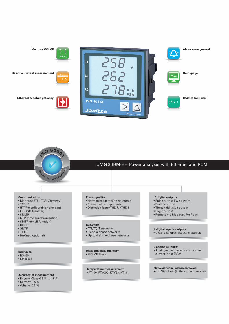
Network visualisation software• GridVis®-Basic (in the scope of supply)
UMG 96 RM-E – Power analyser with Ethernet and RCM
3 digital inputs/outputs• Usable as either inputs or outputs
2 digital outputs• Pulse output kWh / kvarh• Switch output• Threshold value output• Logic output• Remote via Modbus / Profibus
Temperature measurement• PT100, PT1000, KTY83, KTY84
Interfaces• RS485• Ethernet
Communication• Modbus (RTU, TCP, Gateway)• TCP/IP• HTTP (configurable homepage)• FTP (file transfer)• SNMP• NTP (time synchronisation)• SMTP (email function)• DHCP• SNTP• TFTP• BACnet (optional)
Accuracy of measurement• Energy: Class 0.5 S (… / 5 A)• Current: 0.5 %• Voltage: 0.2 %
Networks• TN, TT, IT networks• 3 and 4-phase networks• Up to 4 single-phase networks
Measured data memory • 256 MB Flash
Power quality • Harmonics up to 40th harmonic• Rotary field components• Distortion factor THD-U / THD-I
2 analogue inputs• Analogue, temperature or residual
current input (RCM)
Residual current measurement
BACnet (optional)
Homepage
Alarm managementMemory 256 MB
Ethernet-Modbus gateway
2
UMG 96RM-E
• Measurement, monitoring and checking of electrical characteristics in energy distribution systems
• Recording of load profiles in energy management systems (e.g. ISO 50001)
• Acquisition of the energy consumption for cost centre analysis• Measured value transducer for building management systems or
PLC (Modbus)• Monitoring of power quality characteristics, e.g. harmonics up to
40th harmonic• Residual current monitoring (RCM)
Areas of application
Main features
Universal meter
• Operating current monitoring for general electrical parameters• High transparency through a multi-stage and scalable
measurement system in the field of energy measurement• Acquisition of events through continuous measurement with
200 ms high resolution
RCM device
• Continuous monitoring of residual currents (Residual Current Monitor, RCM)
• Alarming in case a preset threshold fault current reached• Near-realtime reactions for triggering countermeasures• Permanent RCM measurement for systems in permanent
operation without the opportunity to switch off
Energy measurement device
• Continuous acquisition of the energy data and load profiles• Essential both in relation to energy efficiency and for the safe
design of power distribution systems
Harmonics analyser / event recorder
• Analysis of individual harmonics for current and voltage• Prevention of production downtimes • Significantly longer service life for equipment• Rapid identification and analysis of power quality fluctuations by
means of user-friendly tools (GridVis®)
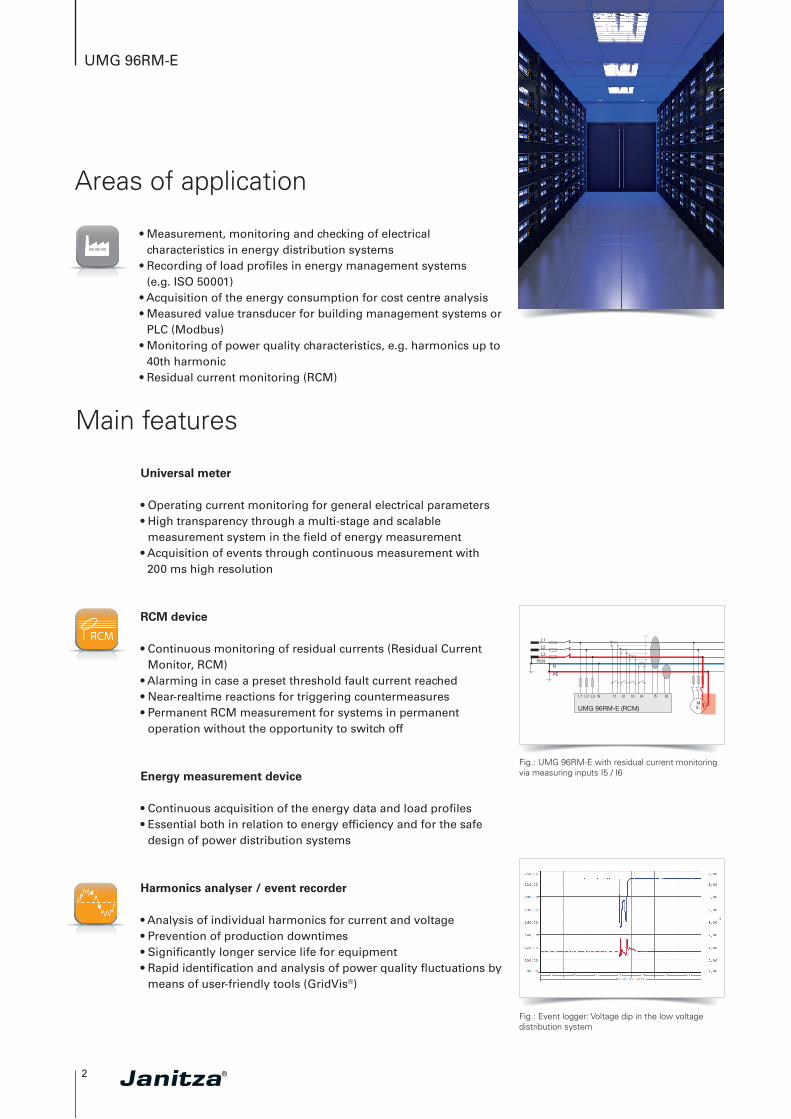
Fig.: UMG 96RM-E with residual current monitoring via measuring inputs I5 / I6
Fig.: Event logger: Voltage dip in the low voltage distribution system
3
UMG 96RM-E
Extensive selection of tariffs
• 7 tariffs each for effective energy (consumption, delivery and without backstop)
• 7 tariffs each for reactive energy (inductive, capacitive and without backstop)
• 7 tariffs for apparent energy• L1, L2 and L3, for each phase
Highest possible degree of reliability
• Continuous leakage current measurement• Historical data: Long-term monitoring of the residual current
allows changes to be identified in good time, e.g. insulation faults
• Time characteristics: Recognition of time relationships• Prevention of neutral conductor carryover• RCM threshold values can be optimized for each individual
case: Fixed, dynamic and stepped RCM threshold value• Monitoring of the CGP (central ground point) and the sub-
distribution panels
Analysis of fault current events
• Event list with time stamp and values• Presentation of fault currents with characteristic and duration• Reproduction of phase currents during the fault current surge• Presentation of the phase voltages during the fault current surge
Analysis of the harmonic fault current components
• Frequencies of the fault currents (fault type)• Current peaks of the individual frequency components in A and %• Harmonics analysis up to 40th harmonic• Maximum values with real-time bar display
Digital IOs
• Extensive configuration of IOs for intelligent integration, alarm and control tasks
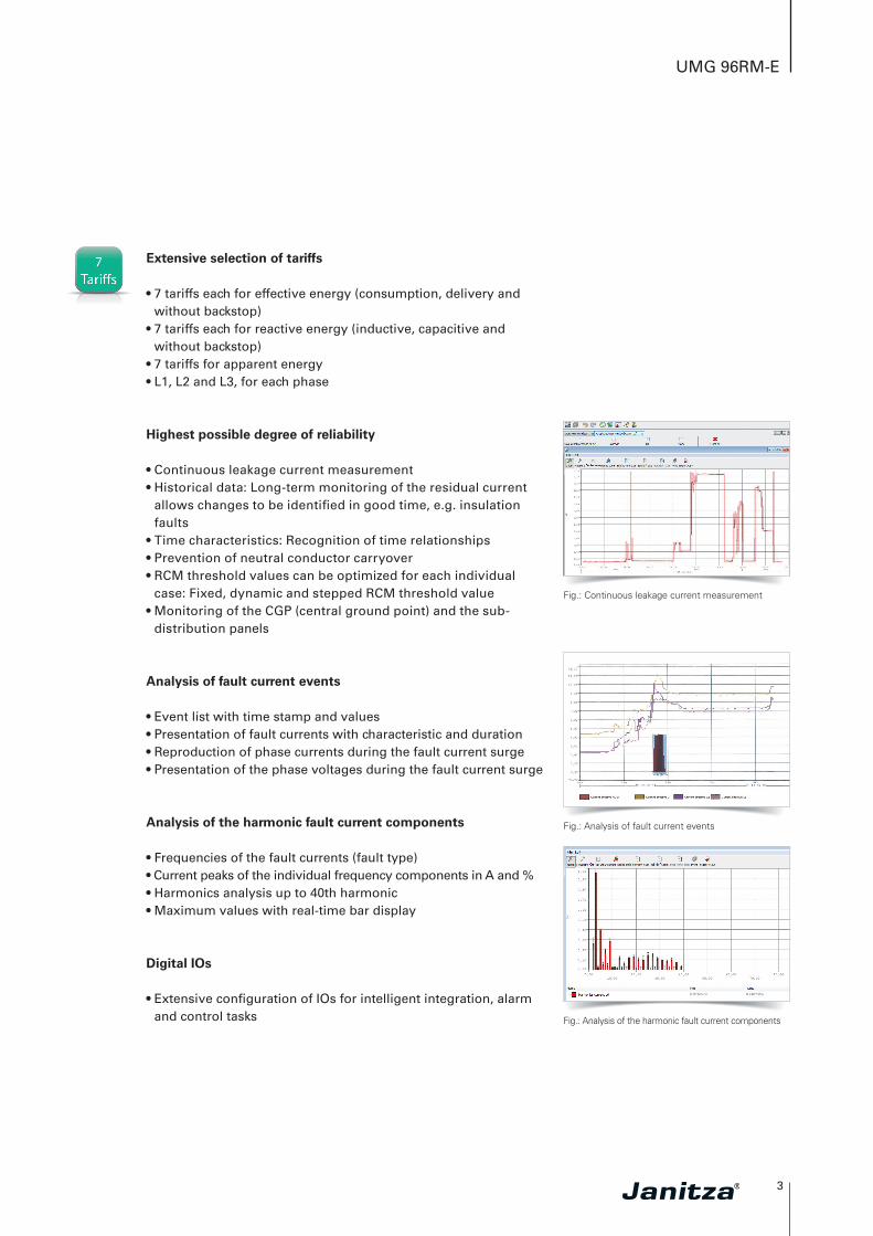
Fig.: Continuous leakage current measurement
Fig.: Analysis of fault current events
Fig.: Analysis of the harmonic fault current components
4
UMG 96RM-E
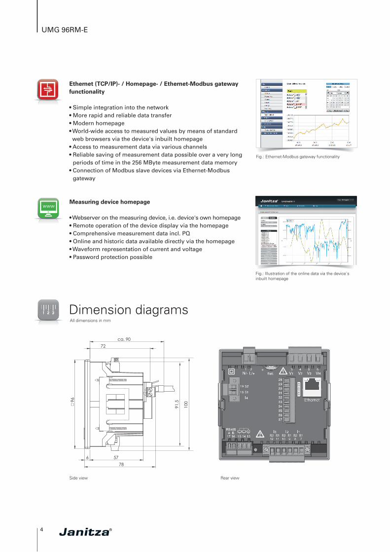
Dimension diagramsAll dimensions in mm
Side view Rear view
Ethernet (TCP/IP)- / Homepage- / Ethernet-Modbus gateway functionality
• Simple integration into the network• More rapid and reliable data transfer• Modern homepage• World-wide access to measured values by means of standard web browsers via the device's inbuilt homepage
• Access to measurement data via various channels • Reliable saving of measurement data possible over a very long
periods of time in the 256 MByte measurement data memory• Connection of Modbus slave devices via Ethernet-Modbus
gateway
Fig.: Ethernet-Modbus gateway functionality
ca. 90 72
96
6 57 78
91,5
100
Measuring device homepage
• Webserver on the measuring device, i.e. device's own homepage• Remote operation of the device display via the homepage • Comprehensive measurement data incl. PQ• Online and historic data available directly via the homepage• Waveform representation of current and voltage• Password protection possible
Fig.: Illustration of the online data via the device's inbuilt homepage

5
UMG 96RM-E
Typical connection
Device overview and technical data
L2 L3N L1
Load
PE
Fig.: Connection example residual current measurement and PE monitoring
UMG 96RM-E
Item number 52.22.036Supply voltage AC 20 ... 250 V AC
Supply voltage DC 20 … 300 V DC
Item number (ETL)*1 52.22.033Supply voltage AC 95 ... 240 V AC
Supply voltage DC 100 ... 300 V DC
GeneralUse in low and medium voltage networks •
Accuracy voltage measurement 0.2 %
Accuracy current measurement 0.5 %
Accuracy active energy (kWh, …/5 A) Class 0.5
Number of measurement points per period 426
Uninterrupted measurement •
RMS - momentary valueCurrent, voltage, frequency •
Active, reactive and apparent power / total and per phase •
Power factor / total and per phase •
Energy measurementActive, reactive and apparent energy [L1, L2, L3, ∑ L1–L3] •
Number of tariffs 14
Recording of the mean valuesVoltage, current / actual and maximum •
Active, reactive and apparent power / actual and maximum •
Frequency / actual and maximum •
Demand calculation mode (bi-metallic function) / thermal •
Comment: For detailed technical information please refer to the operation manual and the Modbus address list.
• = included - = not included
*1 The Intertek-ETL sign is well respected and widely accepted in the USA and Canada. It serves as verification of compliance with the relevant standards, e.g. UL, CSA, NEC, NFPA, NSF, ANSI, NOM. Further information on ETL can be found at http://www.intertek.de/elektronik/etl-zeichen/. Source: www.intertek.de
Fig.: Connection example with temperature and residual current measurement
S2 S1
S2
S2
S1
S1
Digital-Eingänge/Ausgänge
UMG 96RM-E (RCM)
L1
L2
L3
Spannungsmessung
3 4 5 6
StrommessungVersorgungs-spannung
1 2
RS485
16 17
B
A
B A
Verb
rauc
her
230V/400V 50Hz
I4
19 18
N
28 29 30 31 32 33 34 35 36
Analog-Eingänge
13 14 15
24V DC
K1 K2
=-
+
Eth
erne
t10
/100
Bas
e-T
PC
K3 K4 K5
=-
+
=+
-
37
RJ4
5
0-30 mA
S2 S1
IDIFF
I5 I6
PT100
S1 S2 S3
Gruppe 1 Gruppe 2
V1 V2 V3 VNN/- L/+S2 S1 S2 S1 S2 S1 S2 S1
Power supply voltage
Current measurementMeasuring voltage
Digital inputs/outputs Analog inputs
Load
s
6
UMG 96RM-E
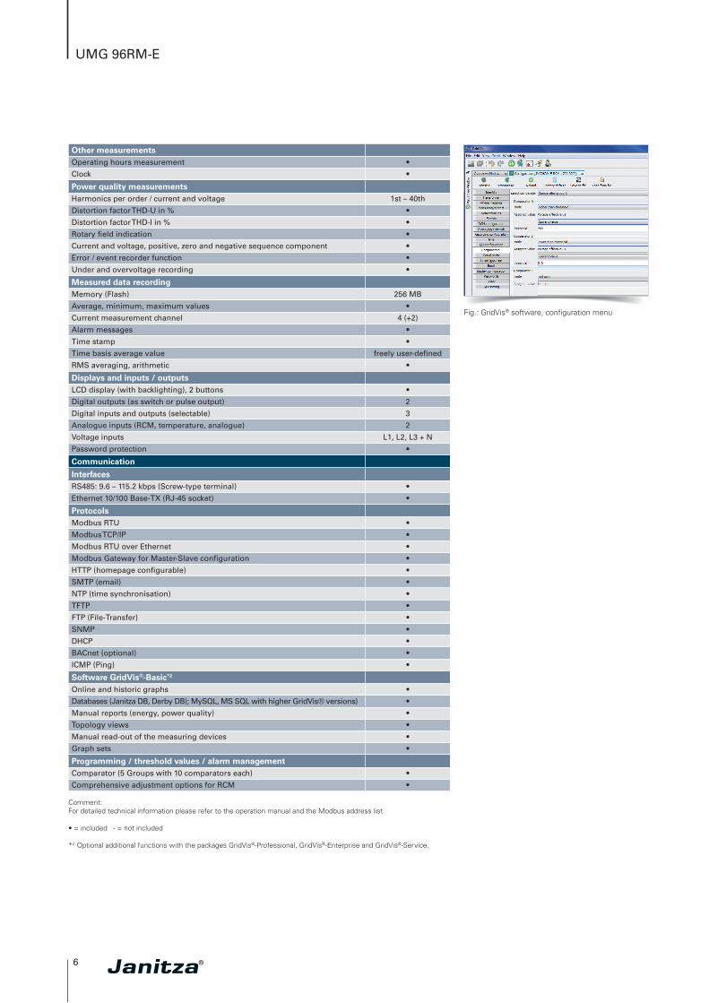
Fig.: GridVis® software, configuration menu
Other measurementsOperating hours measurement •
Clock •
Power quality measurementsHarmonics per order / current and voltage 1st – 40th
Distortion factor THD-U in % •
Distortion factor THD-I in % •
Rotary field indication •
Current and voltage, positive, zero and negative sequence component •
Error / event recorder function •
Under and overvoltage recording •
Measured data recordingMemory (Flash) 256 MB
Average, minimum, maximum values •
Current measurement channel 4 (+2)
Alarm messages •
Time stamp •
Time basis average value freely user-defined
RMS averaging, arithmetic •
Displays and inputs / outputsLCD display (with backlighting), 2 buttons •
Digital outputs (as switch or pulse output) 2
Digital inputs and outputs (selectable) 3
Analogue inputs (RCM, temperature, analogue) 2
Voltage inputs L1, L2, L3 + N
Password protection •
Communication
InterfacesRS485: 9.6 – 115.2 kbps (Screw-type terminal) •
Ethernet 10/100 Base-TX (RJ-45 socket) •
ProtocolsModbus RTU •
Modbus TCP/IP •
Modbus RTU over Ethernet •
Modbus Gateway for Master-Slave configuration •
HTTP (homepage configurable) •
SMTP (email) •
NTP (time synchronisation) •
TFTP •
FTP (File-Transfer) •
SNMP •
DHCP •
BACnet (optional) •
ICMP (Ping) •
Software GridVis®-Basic*2
Online and historic graphs •
Databases (Janitza DB, Derby DB); MySQL, MS SQL with higher GridVis® versions) •
Manual reports (energy, power quality) •
Topology views •
Manual read-out of the measuring devices •
Graph sets •
Programming / threshold values / alarm managementComparator (5 Groups with 10 comparators each) •
Comprehensive adjustment options for RCM •
Comment: For detailed technical information please refer to the operation manual and the Modbus address list.
• = included - = not included
*2 Optional additional functions with the packages GridVis®-Professional, GridVis®-Enterprise and GridVis®-Service.
7
UMG 96RM-E
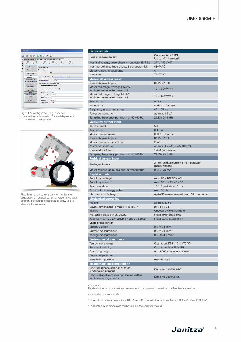
Fig.: RCM configuration, e.g. dynamic threshold value formation, for load-dependent threshold value adaptation
Fig.: Summation current transformer for the acquisition of residual currents. Wide range with different configurations and sizes allow use in almost all applications
Technical data
Type of measurementConstant true RMS Up to 40th harmonic
Nominal voltage, three-phase, 4-conductor (L-N, L-L) 277 / 480 V AC
Nominal voltage, three-phase, 3-conductor (L-L) 480 V AC
Measurement in quadrants 4
Networks TN, TT, IT
Measured voltage inputOvervoltage category 300 V CAT III
Measured range, voltage L-N, AC (without potential transformer)
10 … 300 Vrms
Measured range, voltage L-L, AC (without potential transformer)
18 … 520 Vrms
Resolution 0.01 V
Impedance 4 MOhm / phase
Frequency measuring range 45 ... 65 Hz
Power consumption approx. 0.1 VA
Sampling frequency per channel (50 / 60 Hz) 21.33 / 25.6 kHz
Measured current inputRated current 5 A
Resolution 0.1 mA
Measurement range 0.001 … 6 Amps
Overvoltage category 300 V CAT II
Measurement surge voltage 2 kV
Power consumption approx. 0.2 VA (Ri = 5 MOhm)
Overload for 1 sec. 120 A (sinusoidal)
Sampling frequency per channel (50 / 60 Hz) 21.33 / 25.6 kHz
Residual current input
Analogue inputs2 (for residual current or temperature measurement)
Measurement range, residual current input*3 0.05 ... 30 mA
Digital outputsSwitching voltage max. 60 V DC, 33 V AC
Switching current max. 50 mA Eff AC / DC
Response time 10 / 12 periods + 10 ms
Pulse output (energy pulse) max. 50 Hz
Maximum cable length up to 30 m unscreened, from 30 m screened
Mechanical propertiesWeight approx. 370 g
Device dimensions in mm (H x W x D)*4 96 x 96 x 78
Battery CR2032, 3 V,type Lithium
Protection class per EN 60529 Front: IP40; Back: IP20
Assembly per IEC EN 60999-1 / DIN EN 50022 Front panel installation
Cable cross section
Supply voltage 0.2 to 2.5 mm²
Current measurement 0.2 to 2.5 mm²
Voltage measurement 0.08 to 4.0 mm²
Environmental conditionsTemperature range Operation: K55 (-10 ... +70 °C)
Relative humidity Operation: 0 to 75 % RH
Operating height 0 ... 2,000 m above sea level
Degree of pollution 2
Installation position user-defined
Electromagnetic compatibilityElectromagnetic compatibility of electrical equipment
Directive 2004/108/EC
Electrical appliances for application within particular voltage limits
Directive 2006/95/EC
Comment: For detailed technical information please refer to the operation manual and the Modbus address list.
• = included - = not included
*3 Example of residual current input 30 mA with 600/1 residual current transformer: 600 x 30 mA = 18,000 mA
*4 Accurate device dimensions can be found in the operation manual.
8
UMG 96 RM-E
Equipment safetySafety requirements for electrical equipment for measurement, regulation, control and laboratory use – Part 1: General requirements
IEC/EN 61010-1
Part 2-030: Particular requirements for testing and measuring circuits
IEC/EN 61010-2-030
Noise immunityClass A: Industrial environment IEC/EN 61326-1
Electrostatic discharge IEC/EN 61000-4-2
Voltage dips IEC/EN 61000-4-11
EmissionsClass B: Residential environment IEC/EN 61326-1
Radio disturbanc voltage strength 30 – 1000 MHz IEC/CISPR11/EN 55011
Radiated interference voltage 0.15 – 30 MHz IEC/CISPR11/EN 55011
SafetyEurope CE labelling
USA and Canada ETL variants available
Firmware
Firmware update
Update via GridVis® software.Firmware download (free of charge) from the website:http://www.janitza.com/downloads/
Comment: For detailed technical information please refer to the operation manual and the Modbus address list.
• = included - = not included
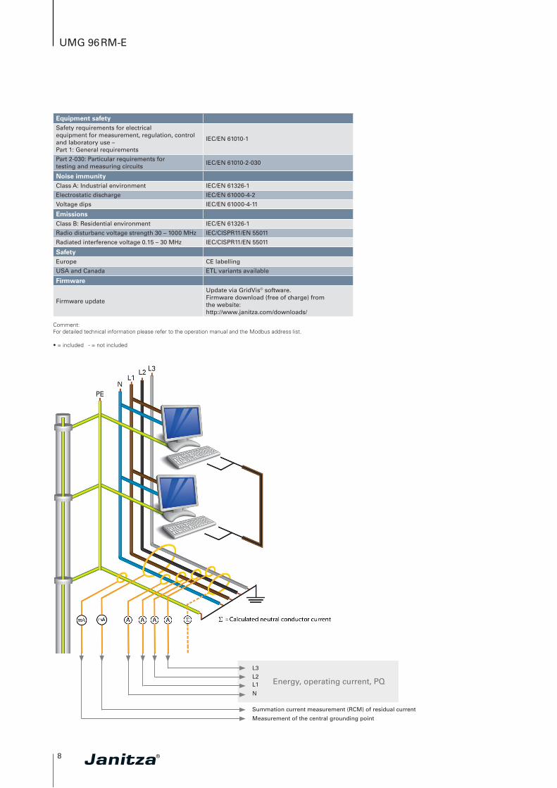
L3L2L1
N
Summation current measurement (RCM) of residual current
Measurement of the central grounding point
Energy, operating current, PQ