usbto232 user guide - maxim integrated
TRANSCRIPT

General DescriptionThe USBTO232 is an adapter board that converts aPC’s USB port into a standard COM port. A COM port isalso known as the standard serial port that usesRecommended Standard 232 (RS-232).
The USBTO232 is included with selected Maxim EV kitsand EV systems that were originally designed for thePC COM port and later updated to also support theUSB port. Data sheets for EV kits and EV systems thatcan use the USBTO232 have been updated to reflectcompatibility and also provide ordering information.Use of the USBTO232 in applications other than thoseEV kits specified by Maxim is not supported.
Important: Before using the USBTO232, see the QuickStart section of this data sheet to correctly install theUSB driver for the appropriate Windows® operatingsystem.
Features USB Powered
USB Driver for Windows 98SE/2000/XP OperatingSystems
USB and I/O Power LED Indicators
Two GPIO LED Indicators
USB Cable Included
8-Pin Signal Header
Proven PCB Layout
Fully Assembled and Tested
US
BT
O2
32
USB-to-COM Port Adapter Board User Guide
________________________________________________________________ Maxim Integrated Products 1
Ordering Information
19-0677; Rev 0; 11/06
For pricing, delivery, and ordering information, please contact Maxim/Dallas Direct! at 1-888-629-4642, or visit Maxim’s website at www.maxim-ic.com.
+ Denotes lead-free and RoHS compliance.
PART PC
INTERFACE OPERATING SYSTEMS
SUPPORTED
USBTO232+ USB Windows 98SE/2000/XP
Component ListWindows is a registered trademark of Microsoft Corp.
DESIGNATION QTY DESCRIPTION
C1 10.01µF ±10%, 50V X7R ceramiccapacitor (0603)TDK C1608X7R1H103K
C2, C3 247pF ±5%, 50V COG ceramiccapacitors (0603)TDK C1608C0G1H470J
C4–C8, C11,C12
70.1µF ±10%, 16V X7R ceramiccapacitors (0603)TDK C1608X7R1C104K
C9 14.7µF ±10%, 6.3V X5R ceramiccapacitor (0603)TDK C1608X5R0J475K
C10 11µF ±10%, 6.3V X5R ceramiccapacitor (0603)TDK C1608X5R0J105K
D1 1Red LED (0603)Panasonic LNJ208R8ARA
D2 1Green LED (0603)Stanley Electric BG1111C-TRPanasonic LNJ314G8TRA
FB1 140Ω @ 100MHz, 1.5A ferrite bead(0805)Steward MI0805K400R-10
H1 1 8-pin header
JU1, JU2, JU3 3 3-pin headers
DESIGNATION QTY DESCRIPTION
P1 1USB type B right-angle femalereceptacle connectorAssmann AU-Y1007-R
P2 1Short DB9 right-angle malereceptacle connector (withoutcable-locking screws)
R1, R2 2270Ω ±5% resistors (0603)(use lead-free parts only)
U1 1USB-to-UART converterFTDI FT232RL (28-pin SSOP)
U2 1 MAX213EEAI+ (28-pin SSOP)
— 3 Shunts
— 1 USBTO232+ PCB
— 1 USB high-speed A-to-B 6ft cable
Note: Indicate the Maxim EV kit that you are using when con-tacting this component supplier.
SUPPLIER PHONE WEBSITE
TDK 847-803-6100 www.component.tdk.com
Component Supplier

US
BT
O2
32
2 _______________________________________________________________________________________
Quick StartThe following instructions are for installing USB driversand the EV kit software. Once the USB drivers and EVkit software have been installed, refer to the Quick Startsection of the appropriate EV kit data sheet for EV kit-specific instructions.
Recommended Equipment• USBTO232 board (USB cable included)
• Maxim EV kit (or EV system) with a COM port PC connection
• Corresponding EV kit data sheet
• User-supplied PC with a USB port
Note: In the following sections, software-related itemsare identified by bolding. Text in bold refers to itemsdirectly from the EV kit software. Text in bold andunderlined refers to items from the Windows98SE/2000/XP operating system.
Procedure1) Visit the Maxim website (www.maxim-ic.com/evkit-
software) to download the latest version of the EVkit software that supports USB. Save the EV kit soft-ware to a temporary folder and uncompress the file,if it is a .zip file.
2) Install the EV kit software on your computer by run-ning the INSTALL.EXE program inside the tempo-rary folder. The program fi les are copied toC:\Program Files\MAXxxxxx and icons are creat-ed in the Windows Start | Programs menu.
3) Uncompress the USB driver f i le copied intoC:\Program Files\MAXxxxxx after the software isinstalled. If you are using Windows 98SE, uncom-press the USB_Driver_98_ME_V1.09.zip file. If youare using Windows 2000/XP, uncompress theUSB_Driver_XP_2K_V2.00.zip file. Uncompressthe contents of the .zip fi le into C:\ProgramFiles\MAXxxxxx.
4) Verify that the following USBTO232 jumpers are inthe default positions:
JU1: (1-2)
JU2: (2-3)
JU3: (2-3)
5) Connect the included USB cable from the PC’s USBport (Type A) to the Type B USB connector on theUSBTO232 board.
6) Verify that the red VCC power LED (D1) lights up.Also verify that the green VCCIO power LED (D2)lights up.
7) Go to the appropriate USB Driver Installation sec-tion in this data sheet for the version of Windowsyou are using and return to step 8 when finished.For example, if you are using Windows XP, go tothe Windows XP USB Driver Installation section.
Windows XP: Page 3
Windows 2000: Page 11
Windows 98SE: Page 25
8) Connect the USBTO232 board to the EV kit (or EVsystem) by connecting the male DB9 connector onthe USBTO232 board to the female DB9 connectoron the EV kit.
9) Refer to the Quick Start section of the appropriate EVkit data sheet for further EV kit-specific instructions.
Detailed Description of HardwareThe USBTO232 is an adapter board that converts aPC’s USB port into a standard COM port. TheUSBTO232 board has three configurable jumpers: JU1,JU2, and JU3. Jumper JU1 is the I/O supply selection(see Table 1), jumper JU2 is the USB power-supplyindicator (see Table 2), and jumper JU3 is the 3.3Vpower-supply indicator (see Table 3).
Table 1. I/O Supply Selection (VCCIO)
*Default position.
Table 2. USB Power-Supply Indicator(VCC–D1)
*Default position.
Table 3. 3.3V Power-Supply Indicator(VCC30–D2)
*Default position.
JUMPER SHUNT POSITION DESCRIPTION
1-2* VCCIO = VCC = 5VJU1
2-3 VCCIO = VCC30 = 3.3V
JUMPER SHUNT POSITION DESCRIPTION
1-2General-purpose LEDconnected to CBUS0
JU2
2-3*Indicates USB power presentwhen red LED (D1) is lit
JUMPER SHUNT POSITION DESCRIPTION
1-2General-purpose LEDconnected to CBUS1
JU3
2-3*Indicates regulated 3.3Vpower present when greenLED (D2) is lit
USB-to-COM Port Adapter Board User Guide
US
BT
O2
32
USB-to-COM Port Adapter Board User Guide
_______________________________________________________________________________________ 3
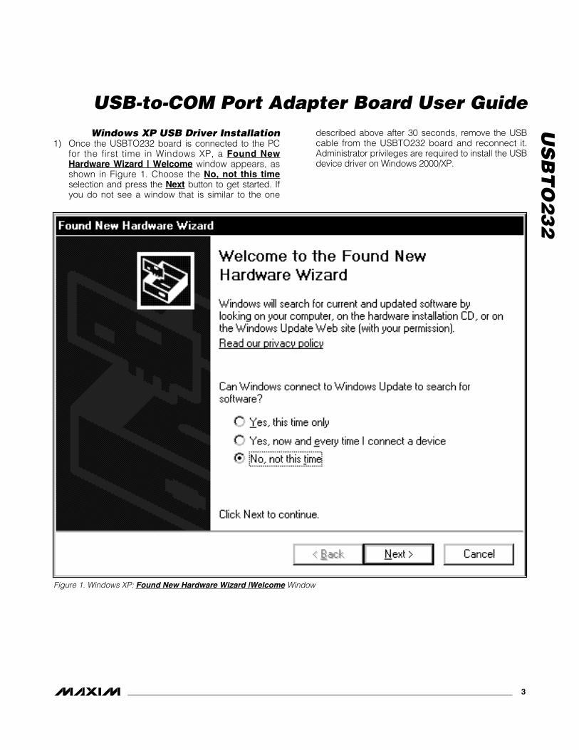
Windows XP USB Driver Installation1) Once the USBTO232 board is connected to the PC
for the first time in Windows XP, a Found NewHardware Wizard | Welcome window appears, asshown in Figure 1. Choose the No, not this timeselection and press the Next button to get started. Ifyou do not see a window that is similar to the one
described above after 30 seconds, remove the USBcable from the USBTO232 board and reconnect it.Administrator privileges are required to install the USBdevice driver on Windows 2000/XP.
Figure 1. Windows XP: Found New Hardware Wizard |Welcome Window

US
BT
O2
32 2) A Found New Hardware Wizard | FTDI FT8U2XX
Device window (Figure 2) appears next. This win-dow asks What do you want the wizard to do?.Choose the Install from a list or specific location(Advanced) option and press the Next button.
Figure 2. Windows XP: Found New Hardware Wizard | FTDI FT8U2XX Device Window
USB-to-COM Port Adapter Board User Guide
4 _______________________________________________________________________________________

_______________________________________________________________________________________ 5
3) At the Found New Hardware Wizard | SearchOptions window (Figure 3), choose the Search forthe best driver in these locations option andcheck the Include this location in the searchcheckbox. Press the Browse button and navigateto the path: C:\Program Files\MAXxxxxx (wherexxxxx represents the Maxim IC part number on the
EV kit being evaluated). Press the Next buttonwhen finished.
US
BT
O2
32
USB-to-COM Port Adapter Board User Guide
Figure 3. Windows XP: Found New Hardware Wizard | Search Options Window

US
BT
O2
32
USB-to-COM Port Adapter Board User Guide
6 _______________________________________________________________________________________
4) The Found New Hardware Wizard | Complete win-dow appears (Figure 4). Press the Finish button.
Figure 4. Windows XP: Found New Hardware Wizard | Complete Window

US
BT
O2
32
USB-to-COM Port Adapter Board User Guide
_______________________________________________________________________________________ 7
5) A Found New Hardware Wizard | Welcome win-dow appears again (Figure 5). Choose the No, notthis time selection and press the Next button.
Figure 5. Windows XP: Found New Hardware Wizard | Welcome Window

US
BT
O2
32 6) The next window is the Found New Hardware
Wizard | USB Serial Port window (Figure 6). Thiswindow asks What do you want the wizard todo?. Choose the Install from a list or specificlocation (Advanced) option and press the Nextbutton.
USB-to-COM Port Adapter Board User Guide
8 _______________________________________________________________________________________
Figure 6. Windows XP: Found New Hardware Wizard | USB Serial Port Window

7) At the Found New Hardware Wizard | SearchOptions window (Figure 7), choose the Search forthe best driver in these locations option andcheck the Include this location in the searchcheckbox. Press the Browse button and navigateto the path: C:\Program Files\MAXxxxxx. Pressthe Next button when finished.
US
BT
O2
32
USB-to-COM Port Adapter Board User Guide
_______________________________________________________________________________________ 9
Figure 7. Windows XP: Found New Hardware Wizard | Search Options Window

US
BT
O2
32 8) The next window is the Found New Hardware
Wizard | Complete window (Figure 8). Press theFinish button.
9) When finished, return to step 8 of the USBTO232Quick Start section.
USB-to-COM Port Adapter Board User Guide
10 ______________________________________________________________________________________
Figure 8. Windows XP: Found New Hardware Wizard | Complete Window

Windows 2000 USB Driver Installation1) Once the USBTO232 board is connected to the PC
for the first time in Windows 2000, a Found NewHardware window appears, as shown in Figure 9.
US
BT
O2
32
USB-to-COM Port Adapter Board User Guide
______________________________________________________________________________________ 11
Figure 9. Windows 2000: Found New Hardware Window

US
BT
O2
32 2) A Found New Hardware Wizard | Welcome window
then appears (Figure 10). Press the Next button.
USB-to-COM Port Adapter Board User Guide
12 ______________________________________________________________________________________
Figure 10. Windows 2000: Found New Hardware Wizard | Welcome Window

3) At the Found New Hardware Wizard | InstallHardware Device Drivers window (Figure 11),choose Search for a suitable driver for my device(recommended) and press the Next button whenfinished.
US
BT
O2
32
USB-to-COM Port Adapter Board User Guide
______________________________________________________________________________________ 13
Figure 11. Windows 2000: Found New Hardware Wizard | Install Hardware Device Drivers Window
US
BT
O2
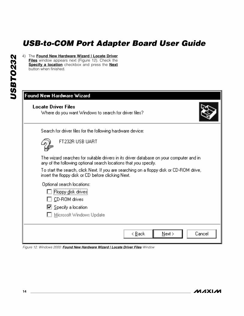
32 4) The Found New Hardware Wizard | Locate Driver
Files window appears next (Figure 12). Check theSpecify a location checkbox and press the Nextbutton when finished.
USB-to-COM Port Adapter Board User Guide
14 ______________________________________________________________________________________
Figure 12. Windows 2000: Found New Hardware Wizard | Locate Driver Files Window
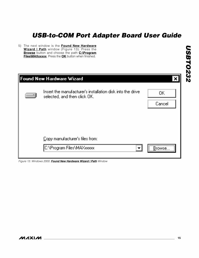
5) The next window is the Found New HardwareWizard | Path window (Figure 13). Press the Browse button and choose the path C:\ProgramFiles\MAXxxxxx. Press the OK button when finished.
US
BT
O2
32
USB-to-COM Port Adapter Board User Guide
______________________________________________________________________________________ 15
Figure 13. Windows 2000: Found New Hardware Wizard | Path Window

US
BT
O2
32 6) The Found New Hardware Wizard | Driver Files
Search Results window is shown in Figure 14. Pressthe Next button after the wizard finds the driver.
USB-to-COM Port Adapter Board User Guide
16 ______________________________________________________________________________________
Figure 14. Windows 2000: Found New Hardware Wizard | Driver Files Search Results Window

7) At the Found New Hardware Wizard | Completewindow (Figure 15), press the Finish button.
US
BT
O2
32
USB-to-COM Port Adapter Board User Guide
______________________________________________________________________________________ 17
Figure 15. Windows 2000: Found New Hardware Wizard | Complete Window
US
BT
O2
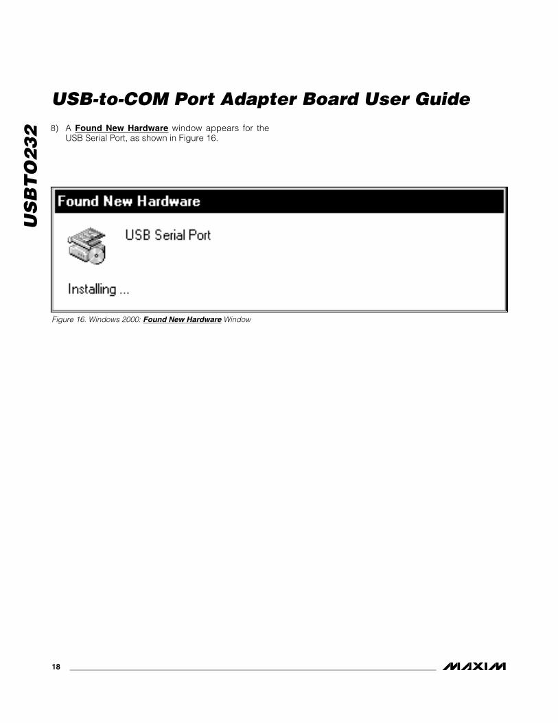
32 8) A Found New Hardware window appears for the
USB Serial Port, as shown in Figure 16.
USB-to-COM Port Adapter Board User Guide
18 ______________________________________________________________________________________
Figure 16. Windows 2000: Found New Hardware Window

9) When the Found New Hardware Wizard |Welcome window appears (Figure 17), press theNext button.
US
BT
O2
32
USB-to-COM Port Adapter Board User Guide
______________________________________________________________________________________ 19
Figure 17. Windows 2000: Found New Hardware Wizard | Welcome Window

US
BT
O2
32 10) At the Found New Hardware Wizard | Install
Hardware Device Drivers window (Figure 18),choose Search for a suitable driver for my device(recommended) and press the Next button whenfinished.
USB-to-COM Port Adapter Board User Guide
20 ______________________________________________________________________________________
Figure 18. Windows 2000: Found New Hardware Wizard | Install Hardware Device Drivers Window

11) The Found New Hardware Wizard | Locate DriverFiles window (Figure 19) appears. Check theSpecify a location checkbox and press the Nextbutton when finished.
US
BT
O2
32
USB-to-COM Port Adapter Board User Guide
______________________________________________________________________________________ 21
Figure 19. Windows 2000: Found New Hardware Wizard | Locate Driver Files Window

US
BT
O2
32 12) At the Found New Hardware Wizard | Path win-
dow (Figure 20), press the Browse button andchoose the path C:\Program Files\MAXxxxxx.Press the OK button when finished.
USB-to-COM Port Adapter Board User Guide
22 ______________________________________________________________________________________
Figure 20. Windows 2000: Found New Hardware Wizard | Path Window

13) The Found New Hardware Wizard | Driver FilesSearch Results window ( Figure 21) appears. Pressthe Next button after the wizard finds the driver.
US
BT
O2
32
USB-to-COM Port Adapter Board User Guide
______________________________________________________________________________________ 23
Figure 21. Windows 2000: Found New Hardware Wizard | Driver Files Search Results Window

US
BT
O2
32 14) The next window is the Found New Hardware
Wizard | Complete window (Figure 22). Press theFinish button.
15) When finished, return to step 8 of the USBTO232Quick Start section.
USB-to-COM Port Adapter Board User Guide
24 ______________________________________________________________________________________
Figure 22. Windows 2000: Found New Hardware Wizard | Complete Window

Windows 98SE USB Driver Installation1) Once the USBTO232 board is connected to the PC
for the first time in Windows 98SE, an Add NewHardware Wizard | Start window appears, asshown in Figure 23. Press the Next button to getstarted.
US
BT
O2
32
USB-to-COM Port Adapter Board User Guide
______________________________________________________________________________________ 25
Figure 23. Windows 98SE: Add New Hardware Wizard | Start Window

US
BT
O2
32 2) An Add New Hardware Wizard | Options window
appears next (Figure 24). Choose the Search forthe best driver for your device (Recommended)option and press the Next button when finished.
USB-to-COM Port Adapter Board User Guide
26 ______________________________________________________________________________________
Figure 24. Windows 98SE: Add New Hardware Wizard | Options Window

3) At the Add New Hardware Wizard | SpecifyLocation window (Figure 25), check the Specify alocation checkbox and press the Browse button.Choose the path C:\Program Files\MAXxxxxx\R10906 (where xxxxx represents the Maxim IC partnumber on the EV kit being evaluated). Press theNext button when finished.
US
BT
O2
32
USB-to-COM Port Adapter Board User Guide
______________________________________________________________________________________ 27
Figure 25. Windows 98SE: Add New Hardware Wizard | Specify Location Window

US
BT
O2
32 4) The Add New Hardware Wizard | Search window
appears (Figure 26). Press the Next button oncethe driver has been located.
USB-to-COM Port Adapter Board User Guide
28 ______________________________________________________________________________________
Figure 26. Windows 98SE: Add New Hardware Wizard | Search Window

5) The next window is the Add New Hardware Wizard| Complete window (Figure 27). Press the Finishbutton to complete the driver installation.
6) When finished, return to step 8 of the USBTO232Quick Start section.
US
BT
O2
32
USB-to-COM Port Adapter Board User Guide
______________________________________________________________________________________ 29
Figure 27. Windows 98SE: Add New Hardware Wizard | Complete Window

US
BT
O2
32
USB-to-COM Port Adapter Board User Guide
30 ______________________________________________________________________________________
Figure 28. USBTO232 Schematic
MAX
213
P1
VCC
VCC
VCC3
0
5 3 1 9 20 23 22 13 14 17 19
VCCI
0
U1FT
232R
L
U2US
BDM
USBD
P
N.C.
N.C.
OSCI
OSCO
CBUS
4
DCD#
RI#
CTS#
DTR#
AGND
GND
257
1821
26GN
DGN
DTE
ST
SLEE
P#
DCD# RI
#
CTS#
DTR#
12 10 6 11 2
JU1
12 4
3
FB1
C10.
01µ
F C247
pF
C11
0.1µ
F
C347
pF
P1-1
P1-2
16 15 8 24 27 28
P1-3
P1-4
USB
TYPE
B
H1
HEAD
ER 8
PIN
C7 0.1µ
F
C6 0.1µ
F
C10
1µF
C40.
1µF
C50.
1µF
H1-1
H1-2
H1-3
H1-4
H1-5
H1-6
H1-7
H1-8
VCC
VCC
C80.
1µF
C94.
7µF
T3OU
T
27CT
S
VCC
VCC
VCC
V CC
CTS#
SLEE
P#
T1OU
T
T2OU
T
R2IN
DTR
TXDA
TA RTS
RXDA
TA
1 2 3 4
R2OU
T5
T2IN
6
T1IN
7
R1OU
T8
R3IN
28T4
OUT
26R3
OUT
23R4
IN
24EN
21T4
IN
20T3
IN
22R4
OUT
25SH
DN
R1IN
DSR
9 11 13
GND
10C1
-14
C1+
V+12
RI RI#
DTR#
19R5
OUT
18R5
IN
DCD#
DCD
CBUS
0
17V-
16C2
-
15C2
+
JU2
12
3
D1
R1 270Ω
VCC3
0
JU3
12
3
D2
R2 270Ω
RESE
T#
RESE
T#
RXD
RTS# TXD
DSR#
VCC
CBUS
0
CBUS
1
CBUS
2
CBUS
3
3V3O
UT
C12
0.1µ
F
VCC3
0
CBUS
3
CBUS
2
CBUS
1
P2
DB9
TYPE
DTE
P2-1
P2-2
P2-3
P2-4
P2-5
P2-6
P2-7
P2-8
P2-9
CBUS
0
CBUS
1
DCD
RXDA
TA
TXDA
TA DTR
DSR
RTS
CTS RI
US
BT
O2
32
USB-to-COM Port Adapter Board User Guide
Maxim cannot assume responsibility for use of any circuitry other than circuitry entirely embodied in a Maxim product. No circuit patent licenses areimplied. Maxim reserves the right to change the circuitry and specifications without notice at any time.
Maxim Integrated Products, 120 San Gabriel Drive, Sunnyvale, CA 94086 408-737-7600 ____________________ 31
© 2006 Maxim Integrated Products is a registered trademark of Maxim Integrated Products, Inc.
CARDENAS
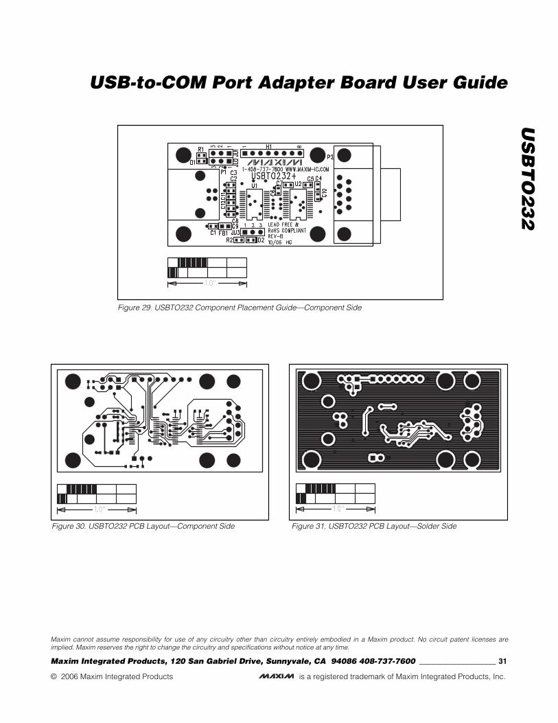
Figure 29. USBTO232 Component Placement Guide—Component Side
Figure 30. USBTO232 PCB Layout—Component Side Figure 31. USBTO232 PCB Layout—Solder Side