using root geometry for fvtx reconstruction zhengyun you peking university los alamos national lab...
TRANSCRIPT

Using ROOT geometry for FVTX reconstruction
Zhengyun You
Peking University
Los Alamos National Lab
Jan 22, 2007

Outline
Detector data flow ( pisa -> ROOT -> offline);
Work plan and current status;
Advantages;
Summary;
Automatic detector construction; Consistency in simulation and reconstruction; Powerful support from ROOT;
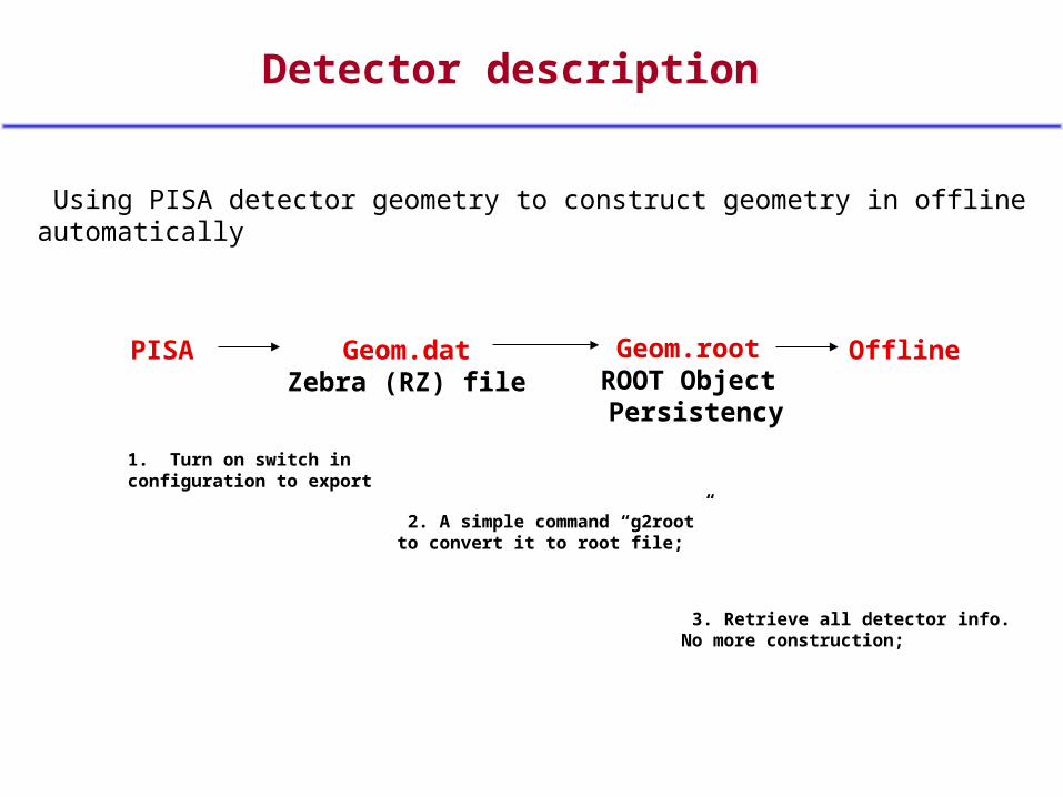
2. A simple command “g2root”to convert it to root file;
Detector description
Using PISA detector geometry to construct geometry in offline automatically
PISA Geom.datZebra (RZ) file
Geom.rootROOT Object Persistency
Offline
1. Turn on switch in configuration to export
3. Retrieve all detector info.No more construction;

ROOT initialization in offline
Geom.root Offline (FvtxGeom)
Set TGeoPhysicalNode to each GeomObject in Offline
Arm
Station
Sector
Plane
Radius
Column
Strip

ROOT initialization in offline
Geom.root FvtxRadius (SI Sensor)
1. Path name is the only TAG to identify an unique phy_node;
2. From phy_node, get everything you need…;
proteced : TGeoPhysicalNode *_phy_node;
*_phy_node = gGeoManager->MakePhyscialNode( “HALL_1/SIEN_1/SICG_1/SI05_1/SIPB_06/SISI_2” )

Advantage 1 : detector construction
Old modeset ( values );
ROOT modeset ( TGeoPhysicalNode * );
FvtxStation : set_z(); set_inner_radius(); set_outer_radius(); …FvtxSector : set_z(); set_deltaz(); set_inner_radius(); set_outer_radius(); set_phi_begin(); set_phi_end(); …FvtxPlane : set_z(); set_inner_radius(); set_outer_radius(); …FvtxRadius : set_z(); set_inner_radius(); set_outer_radius(); set_phi_begin();
FvtxStation : set_phy_node();FvtxSector : set_phy_node();FvtxRadius : set_phy_node();
Hard construction work by hand, still lost much detector info;
Construction done automatically by ROOT, keep all detector info;

Advantage 2 : detector consistency
Old mode ROOT mode
Almost impossible to exactly describe a geom object by yourself;
All geom object are exactly consistentwith those in simulation;
Example : a sensor
set_phi_begin()
set_phi_end()
set_outer_radius()
set_inner_radius()

Advantage 2 : detector consistency
ROOT mode : change detector geometry to whatever you want in PISA;
Position Rotation Material Anything
……
Shape
Without changing any line of code in offline packages;
Because … Path name is the only TAG to identify an unique phy_node,You don’t work with values, but work with pointers.
So that ... Very useful for detector concept design
it becomes easy to compare performance of two different geometry design after reconstruction,Simply replace geom_v1.root with geom_v2.root,Without modifying code;

Advantage 3 : using ROOT functions
1. Hard work;
2. Bugs, not enough test;
3. Desperate when complicate; strange shape, many levels of coordinate transform, composite materials, …
Writing your own functions Using ROOT functions
1. Easy work (1 line of code in most cases)
2. Trustworthy (tested in many programs)
3. Resolve complicate problems; a standard geometry system, supporting many kinds of shapes, supporting any level of coordinate transform, a standard material description system; …

3.1 Coordinate transformation
Using local coordinate makes work easier;
“HALL_1/SIEN_1/SICG_1/SI05_1/SIPB_06/SISI_2”
5 times transformation looks difficult;But how easy in ROOT…
phy_node -> GetHMatrix( -1 * phy_node->GetLevel() ) -> LocalToGlobal( point );-5
-1-2
Vice verse, …… -> GlobalToLocal( point );
Digitization

3.2 Shape contains a point
We can only judge with simple shapes;
FvtxSector : set_z(); set_deltaz(); set_inner_radius(); set_outer_radius(); set_phi_begin(); set_phi_end();
FvtxSector : contains (point)
ROOT support > 20 basic shapes;
phy_node -> GetShape() -> Contains (point)
More boolean shapes;

3.3 Get material info
phy_node -> InspectMaterial();

3.4 Checkng overlaps
Check overlaps and extrusions between nodes by setting limit;

float Stereo angle=
"-17.9909"

doubleStereo angle=
"-17.99087476710785"

Work plan
Step 1 : • Modify geometry package FvtxGeom only;• Keep all current functions and data initialization mode for each class; • Add ROOT initialization mode and add get_...() functions in ROOT mode;• All current macros still run with old mode;• To switch to ROOT initialization and getting info mode , simply add FVTXGEOM::set_root_initialized();
FvtxRadius : set_z(); get_z(); set_inner_radius(); get…(); set_outer_radius(); get…(); set_phi_begin(); …
FvtxRadius : contains( point ); { … }
FvtxRadius : contains( point );{ _phy_node -> GetShape() -> Contains( point); }
If _root_initialized …
FvtxRadius : get_z();
{ transform local center to global coordinate and get z_global; }

Test
FVTXGEOM::set_root_initialized();
Test 1 : Print all get_ info to compare directly… They are close but different.
Test 2 : Use reconstructed track eval ntuples to compare… Match MuReco tracks and FvtxReco tracks.
Test with 30k mu tracks in W events with old mode, 57% no matching svx tracsk;
Reason 1 : 25% muon’s parents are neutral in fvtx and not hits. 2 : geometry inconsistency makes hits lost; (offline geometry not up-to-date)
Switch to ROOT initialized, 20% no match, due to neutral parent; check nhitsf and nPisaHit, Correct detector response hits ratio > 99%;

Work plan
Step 1 : finished, code committed into cvs, but more test is necessary.
Step 2 : • Use coordinate transformation and contains to do most work in fvtxoo and fvtx_subsysreco;
• Use set_() and get_() values as little as possible;
• If possible, and after enough test (several months), switch to ROOT mode;

Summary
Use PISA geometry for offline reconstruction realized in first step;
Always keep geometry consistency in simu and reco;Easy to compare performance of simu. and reco. between two geometry designs;
Decease work of writing and maintaining offline code;
Use ROOT functions to do difficult work in an easy way;Reconstruction could focus on algorithm but not geometry;

Tips on using ROOT mode
1. http://p25ext.lanl.gov/~hubert/phenix/silicon/simulations/jan07/geom_geant_root.htmlto see how to get the geom_1.root,Rename it to fvtxgeom.root and put it in your working directory.
2. Check out fvtxgeom package, make, (maybe fvtxoo, fvtx_subsysreco should be rebuild)Copy fvtxgeom.dat to your working directory. (PISA only construct to SI sensor, (FvtxRadius), Column and Strips still need fvtxgeom.dat)
3.Add FVTXGEOM::set_root_initialized(); to your current macros (Fun4Muons_Pisa.C Fun4Muons_RecoDST_sim.C)Or you can get them from /direct/phenix+data12/youzy/fvtxtest/wrk
4. If FVTXGEOM::set_root_initialized(); is not added,everything keeps the same as before so that you can compare between the two modes;
5. A macro root_geom_test.C in fvtxgeom package could print values for comparison; (// FVTXGEOM::set_root_initialized(); to switch)