vbo3 user manual - omicron
TRANSCRIPT

VBO3User Manual

Manual version: ENU 1210 05 02 - Year: 2018
© OMICRON electronics. All rights reserved.
This manual is a publication of OMICRON electronics. All rights including translation reserved.Reproduction of any kind, for example, photocopying, microfilming, optical character recognitionand/or storage in electronic data processing systems, requires the explicit consent of OMICRONelectronics. Reprinting, wholly or in part, is not permitted.
The product information, specifications, and technical data embodied in this manual represent thetechnical status at the time of writing and are subject to change without prior notice.
We have done our best to ensure that the information given in this manual is useful, accurate, up-to-date and reliable. However, OMICRON electronics does not assume responsibility for anyinaccuracies which may be present.
The user is responsible for every application that makes use of an OMICRON product.
OMICRON electronics translates this manual from the source language English into a number of otherlanguages. Any translation of this manual is done for local requirements, and in the event of a disputebetween the English and a non-English version, the English version of this manual shall govern.
VBO3 User Manual
2 OMICRON

Contents
About this manual ............................................................................................................ 4
1 Introduction ...................................................................................................................... 5
1.1 Scope of delivery ................................................................................................................ 5
1.2 Designated use .................................................................................................................. 5
1.3 Declaration of conformity (EU) ........................................................................................... 5
1.4 Cleaning and disposal ........................................................................................................ 6
1.4.1 Cleaning ............................................................................................................................................. 6
1.4.2 Information for disposal and recycling ............................................................................................... 6
2 Safety instructions ........................................................................................................... 7
2.1 Symbols used ..................................................................................................................... 7
2.2 Rules for use ...................................................................................................................... 7
2.3 Safe operation procedures ................................................................................................. 8
2.4 Operator qualifications ....................................................................................................... 8
3 Device overview ............................................................................................................... 9
4 Circuit diagram ................................................................................................................. 10
5 Wiring ................................................................................................................................ 11
5.1 Connecting VBO3 to a CMC 430 ....................................................................................... 12
5.1.1 Max. 300 V output voltage ................................................................................................................. 12
5.1.2 Max. 600 V output voltage ................................................................................................................. 13
5.2 Connecting VBO3 to other CMCs ...................................................................................... 14
6 Configuring VBO3 in the control software ..................................................................... 15
6.1 Configuration in Test Universe ........................................................................................... 15
6.2 Calculation of voltage ratio ................................................................................................. 17
7 Setup with OMICRON transport case ............................................................................. 20
8 Transportation with OMICRON trolley ............................................................................ 21
9 Technical data ................................................................................................................... 22
Support .............................................................................................................................. 23
Contents
OMICRON 3

About this manualThe purpose of this user manual is to familiarize you with VBO3 and to show you how to use it safely,properly, and efficiently. Following the instructions in this user manual will help you to prevent danger,repair costs, and possible down time due to incorrect operation, and it will help you to maintain thereliability and life of VBO3.
This manual is to be supplemented by existing national safety standards for accident prevention andenvironmental protection.
This manual shall always be available at the site where VBO3 is used. It shall be read and observedby all personnel operating VBO3. Reading the user manual of VBO3 alone does not release you fromthe duty of complying with all safety regulations relevant and applicable to working on systems in anypower distribution network.
In addition to the user manual and the applicable safety regulations in the country and at the site ofoperation, the usual technical procedures for safe and competent work shall be heeded.
Keep this manual during the entire service life of the product and always have it available forreference.
This user manual describes the VBO3 hardware, its usage and wiring. In order to get familiarwith CMC test sets, please refer to the corresponding user documentation.
VBO3 User Manual
4 OMICRON
1 Introduction
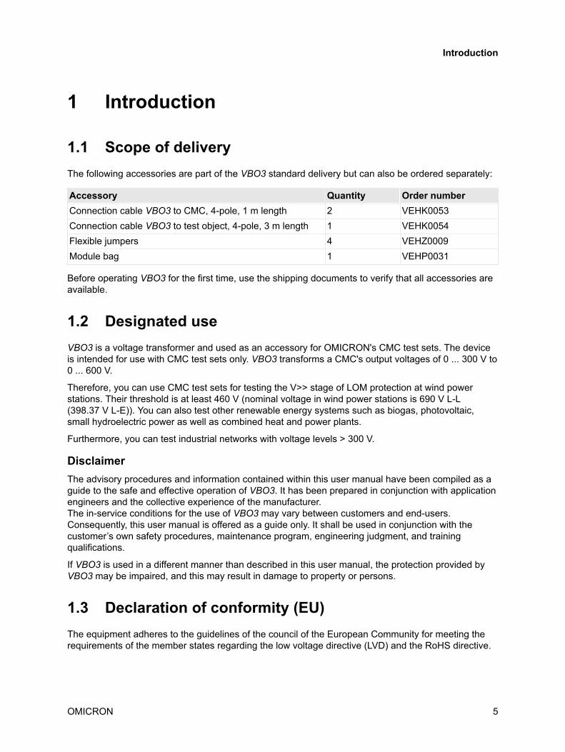
1.1 Scope of deliveryThe following accessories are part of the VBO3 standard delivery but can also be ordered separately:
Accessory Quantity Order numberConnection cable VBO3 to CMC, 4-pole, 1 m length 2 VEHK0053Connection cable VBO3 to test object, 4-pole, 3 m length 1 VEHK0054Flexible jumpers 4 VEHZ0009Module bag 1 VEHP0031
Before operating VBO3 for the first time, use the shipping documents to verify that all accessories areavailable.
1.2 Designated useVBO3 is a voltage transformer and used as an accessory for OMICRON's CMC test sets. The deviceis intended for use with CMC test sets only. VBO3 transforms a CMC's output voltages of 0 ... 300 V to0 ... 600 V.
Therefore, you can use CMC test sets for testing the V>> stage of LOM protection at wind powerstations. Their threshold is at least 460 V (nominal voltage in wind power stations is 690 V L-L(398.37 V L-E)). You can also test other renewable energy systems such as biogas, photovoltaic,small hydroelectric power as well as combined heat and power plants.
Furthermore, you can test industrial networks with voltage levels > 300 V.
DisclaimerThe advisory procedures and information contained within this user manual have been compiled as aguide to the safe and effective operation of VBO3. It has been prepared in conjunction with applicationengineers and the collective experience of the manufacturer.The in-service conditions for the use of VBO3 may vary between customers and end-users.Consequently, this user manual is offered as a guide only. It shall be used in conjunction with thecustomer’s own safety procedures, maintenance program, engineering judgment, and trainingqualifications.
If VBO3 is used in a different manner than described in this user manual, the protection provided byVBO3 may be impaired, and this may result in damage to property or persons.
1.3 Declaration of conformity (EU)The equipment adheres to the guidelines of the council of the European Community for meeting therequirements of the member states regarding the low voltage directive (LVD) and the RoHS directive.
Introduction
OMICRON 5

1.4 Cleaning and disposal
1.4.1 CleaningTo clean VBO3, use a cloth dampened with isopropanol alcohol. Prior to cleaning, always disconnectVBO3 from the CMC test set and from the test object.
1.4.2 Information for disposal and recyclingThis device (including all accessories) is not intended for household use. At the end of its service life,do not dispose of the device with household waste!
For customers in EU countries (incl. European Economic Area)OMICRON devices are subject to the EU Waste Electrical and Electronic EquipmentDirective (WEEE directive). As part of our legal obligations under this legislation,OMICRON offers to take back the device and ensure that it is disposed of byauthorized recycling agents.
For customers outside the European Economic AreaPlease contact the authorities in charge for the relevant environmental regulations inyour country and dispose the OMICRON device only in accordance with your locallegal requirements.
VBO3 User Manual
6 OMICRON

2 Safety instructionsBefore working with VBO3, carefully read the following safety instructions and the safety instructionsfor the CMC test set in use. In addition, we recommend to read the user documentation of the CMCtest set in use.
VBO3 may only be operated by trained personnel. Any misoperations can result in damage to propertyor persons.
Only operate VBO3 after you have read this user manual and fully understood the instructions herein.If you do not fully understand any safety rule or instruction or any part thereof, contact OMICRONelectronics before proceeding (→ page 23).
2.1 Symbols usedIn this manual, the following symbols indicate safety instructions for avoiding hazards.
WARNINGDeath or severe injury can occur if the appropriate safety instructions are not observed.
NOTICEEquipment damage or loss of data possible.
2.2 Rules for use► VBO3 and its accessories must only be used when in a technically sound condition. Its use must
be in accordance with the safety regulations for the specific job site and application.
► Always be aware of the dangers of high voltages. Pay attention to the information provided in thisuser manual and in the user documentation of the CMC test set in use.
► VBO3 is exclusively intended for the application areas specified in section Designated use onpage 5. The manufacturer/distributors are not liable for damage resulting from unintended usage.The user alone assumes all responsibility and risk.
► Keep this manual available on site where the VBO3 is used. The instructions provided in this usermanual and the associated manuals are considered part of the rules governing proper usage.
Safety instructions
OMICRON 7

2.3 Safe operation procedures► Before connecting and disconnecting test objects, verify that all outputs have been turned off and
the installation is dead. Never connect or disconnect a test object while the outputs are active.
► When disconnecting power supply cables or test leads, always start from the device feeding thepower or signal.
► Do not operate VBO3 when explosive gas or vapors are present.
► Only work in well lit areas. If there is not enough daylight, use a strong light to make sure that yousee everything and so ensure your safety.
► Keep your work area clean to avoid accidents.
► If VBO3 seems to be functioning improperly or has visible damages, please contact the OMICRONTechnical Support (→ page 23).
2.4 Operator qualifications► Working on a power distribution network can be extremely dangerous. Familiarize yourself
thoroughly with all the information in this manual. In addition, you need to be familiar with allmanuals of the devices used in the test procedure.
► Testing with VBO3 shall only be carried out by authorized and qualified personnel. Before startingto work, clearly establish the responsibilities of all personnel involved.
► Personnel receiving training, instruction, direction, or education on VBO3 shall remain under theconstant supervision of an experienced operator while working with the equipment.
► Personnel operating VBO3 must be familiar with recognized operating practices and proceduresfor working on high and low voltage systems. They must be familiar with the five safety rules:
• Disconnect completely.
• Secure against re-connection.
• Verify that the installation is dead.
• Carry out grounding and short-circuiting.
• Provide protection against adjacent live parts.
► In addition, the personnel operating VBO3 must be familiar with all necessary personal safetyequipment.
► Testing with VBO3 must comply with all on-site procedures and methods for personal safety andthe safety instructions relevant for each test. They must be discussed with all personnel involved.
VBO3 User Manual
8 OMICRON

3 Device overview
Voltage output triple0 ... 600 V
(incl. N)
Voltage input triple 10 ... 300 V(without N)
Voltage input triple 20 ... 300 V(without N)
Handle (detachable)
If required, you can create the neutral phase for input triple 1 by short-circuiting the phasesV4 prim, V5 prim, and V6 prim (→ Wiring on page 11).
Device overview
OMICRON 9
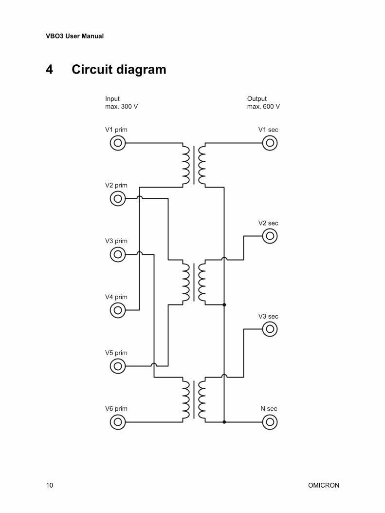
4 Circuit diagram
Inputmax. 300 V
V1 prim V1 sec
V2 sec
V3 sec
N sec
V2 prim
V3 prim
V4 prim
V5 prim
V6 prim
Outputmax. 600 V
VBO3 User Manual
10 OMICRON
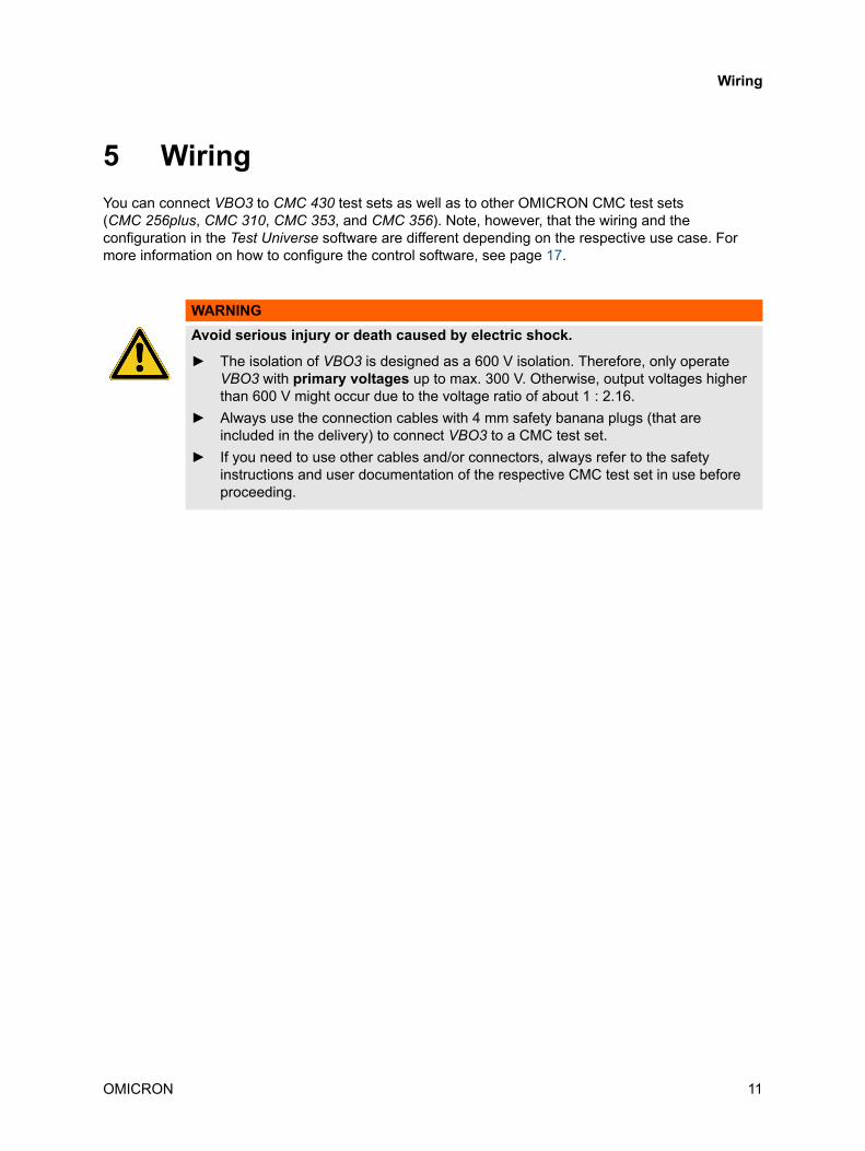
5 WiringYou can connect VBO3 to CMC 430 test sets as well as to other OMICRON CMC test sets(CMC 256plus, CMC 310, CMC 353, and CMC 356). Note, however, that the wiring and theconfiguration in the Test Universe software are different depending on the respective use case. Formore information on how to configure the control software, see page 17.
WARNINGAvoid serious injury or death caused by electric shock.
► The isolation of VBO3 is designed as a 600 V isolation. Therefore, only operateVBO3 with primary voltages up to max. 300 V. Otherwise, output voltages higherthan 600 V might occur due to the voltage ratio of about 1 : 2.16.
► Always use the connection cables with 4 mm safety banana plugs (that areincluded in the delivery) to connect VBO3 to a CMC test set.
► If you need to use other cables and/or connectors, always refer to the safetyinstructions and user documentation of the respective CMC test set in use beforeproceeding.
Wiring
OMICRON 11

5.1 Connecting VBO3 to a CMC 430
5.1.1 Max. 300 V output voltageThere is no star point at the VBO3 voltage inputs. Usually, a star point is not necessary for use with aCMC 430 test set. However, if you would like to use the CMC 430 like one of OMICRON's other CMCtest sets and require an output voltage of only max. 300 V, you need to create a star point.
To create a star point:
• Connect the CMC 430 voltage outputs to one of the VBO3 voltage input triples using a connectioncable with 4 mm safety banana plugs (included in the delivery).
• Use flexible jumpers (included in the delivery) to interconnect the other VBO3 voltage input triple,and thus, create a star point.
• Connect the star point to the CMC 430's neutral phase.
Flexible jumpers
123
N
Connection cable
123N Test object
Connection cable
VBO3
CMC 430
VBO3 User Manual
12 OMICRON
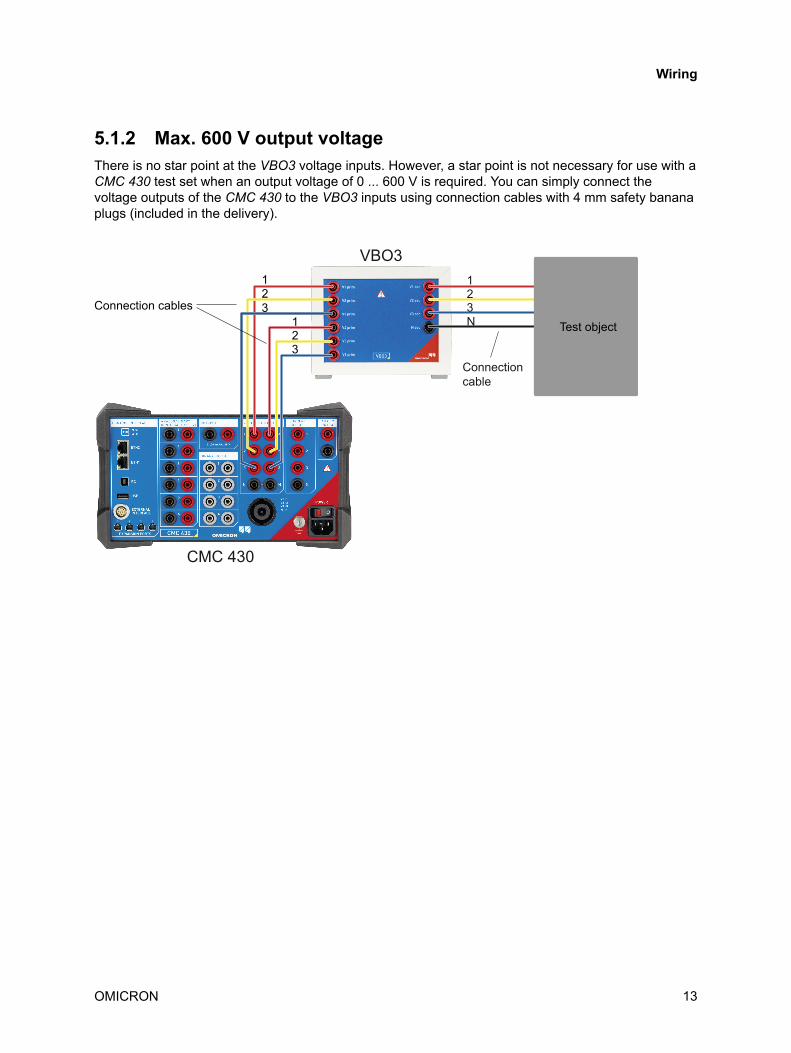
5.1.2 Max. 600 V output voltageThere is no star point at the VBO3 voltage inputs. However, a star point is not necessary for use with aCMC 430 test set when an output voltage of 0 ... 600 V is required. You can simply connect thevoltage outputs of the CMC 430 to the VBO3 inputs using connection cables with 4 mm safety bananaplugs (included in the delivery).
123
123
Connection cables
Connection cable
123N Test object
VBO3
CMC 430
Wiring
OMICRON 13
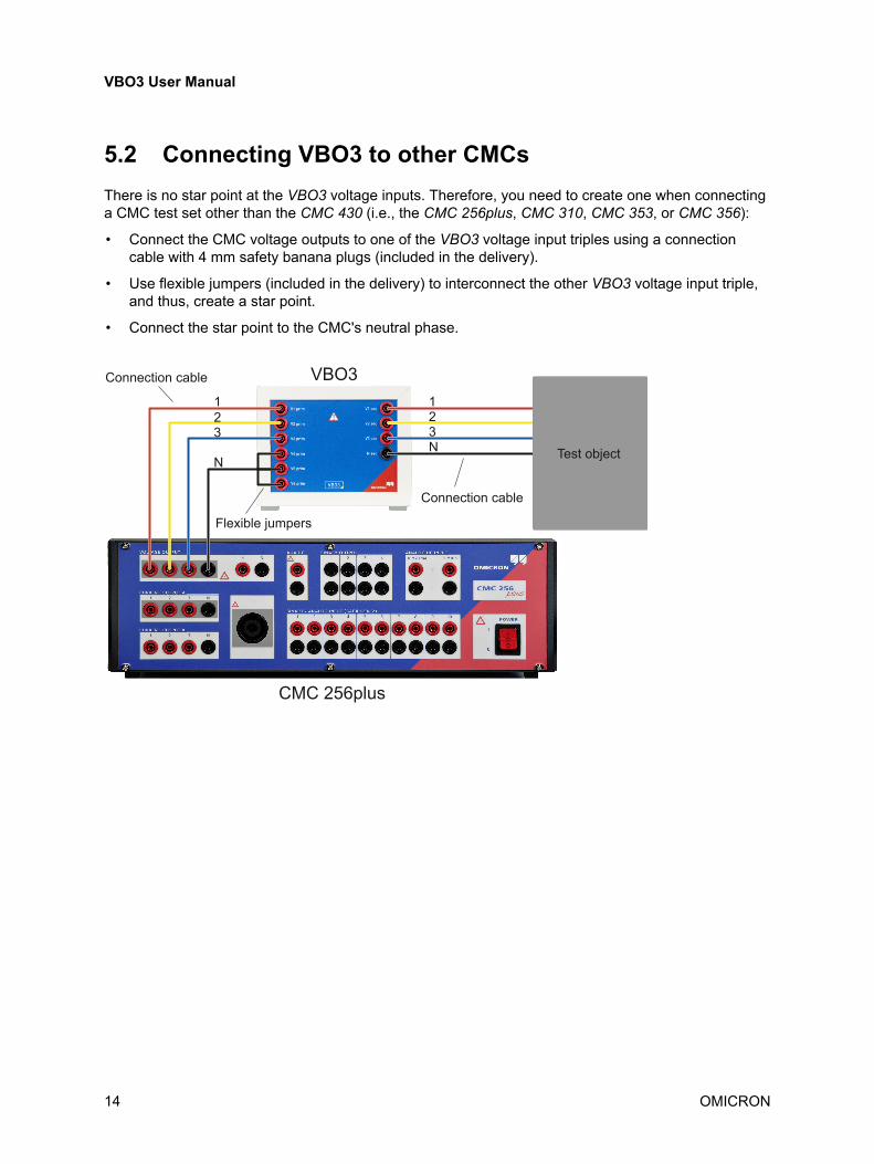
5.2 Connecting VBO3 to other CMCsThere is no star point at the VBO3 voltage inputs. Therefore, you need to create one when connectinga CMC test set other than the CMC 430 (i.e., the CMC 256plus, CMC 310, CMC 353, or CMC 356):
• Connect the CMC voltage outputs to one of the VBO3 voltage input triples using a connectioncable with 4 mm safety banana plugs (included in the delivery).
• Use flexible jumpers (included in the delivery) to interconnect the other VBO3 voltage input triple,and thus, create a star point.
• Connect the star point to the CMC's neutral phase.
Connection cable VBO3
CMC 256plus
Test object
Flexible jumpers
Connection cable
123N
123
N
VBO3 User Manual
14 OMICRON

6 Configuring VBO3 in the control software
6.1 Configuration in Test UniverseTo configure the voltage outputs in Test Universe:
1. Launch a Test Universe module of your choice, and go to the Hardware Configuration.
2. On the General tab, select your CMC from the Test Set(s) list.
3. Click the Details button.
4. In the Output Configuration Details dialog, select a suitable configuration for the voltage outputs:
• CMC 256plus, CMC 310, CMC 353, or CMC 356 with max. 300 V output voltage: Select a3 x 300 V configuration.
Example:
Configuring VBO3 in the control software
OMICRON 15
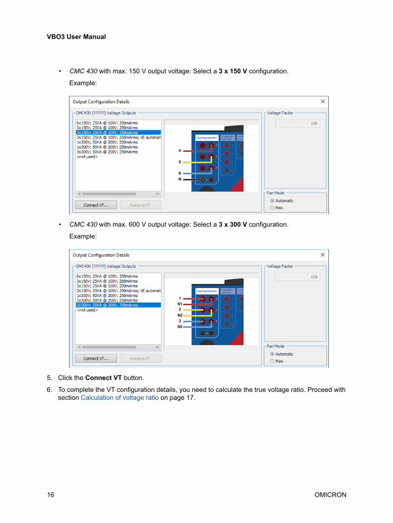
• CMC 430 with max. 150 V output voltage: Select a 3 x 150 V configuration.
Example:
• CMC 430 with max. 600 V output voltage: Select a 3 x 300 V configuration.
Example:
5. Click the Connect VT button.
6. To complete the VT configuration details, you need to calculate the true voltage ratio. Proceed withsection Calculation of voltage ratio on page 17.
VBO3 User Manual
16 OMICRON
6.2 Calculation of voltage ratioWithout load, the voltage ratio between the primary and secondary side of VBO3 is roughly 1 : 2.16. Inreal-life testing scenarios with load, however, the voltage ratio will be lower. To ensure accurate testingconditions, you need to determine the true voltage ratio under load conditions and enter thecorresponding value in Test Universe. You can determine the voltage ratio using a multimeter thatfulfills the requirements for measurement categories CATIII/1000V and CATIV/600V. It is important thatyou always connect the load before measuring the output voltages (see workflow below).
WARNINGAvoid serious injury or death caused by electric shock.
► Always measure the output voltages with a multimeter suitable for up to 1000 Vworking voltage because at the VBO3 outputs, voltages higher than 600 V mightoccur due to the voltage ratio of about 1 : 2.16.
► Do not use a CMC test set for measuring the output voltages. CMC test sets aredesigned for input voltages of max. 600 V. Due to the VBO3's voltage ratio of about1 : 2.16, voltages higher than 600 V might occur.
Configuring VBO3 in the control software
OMICRON 17
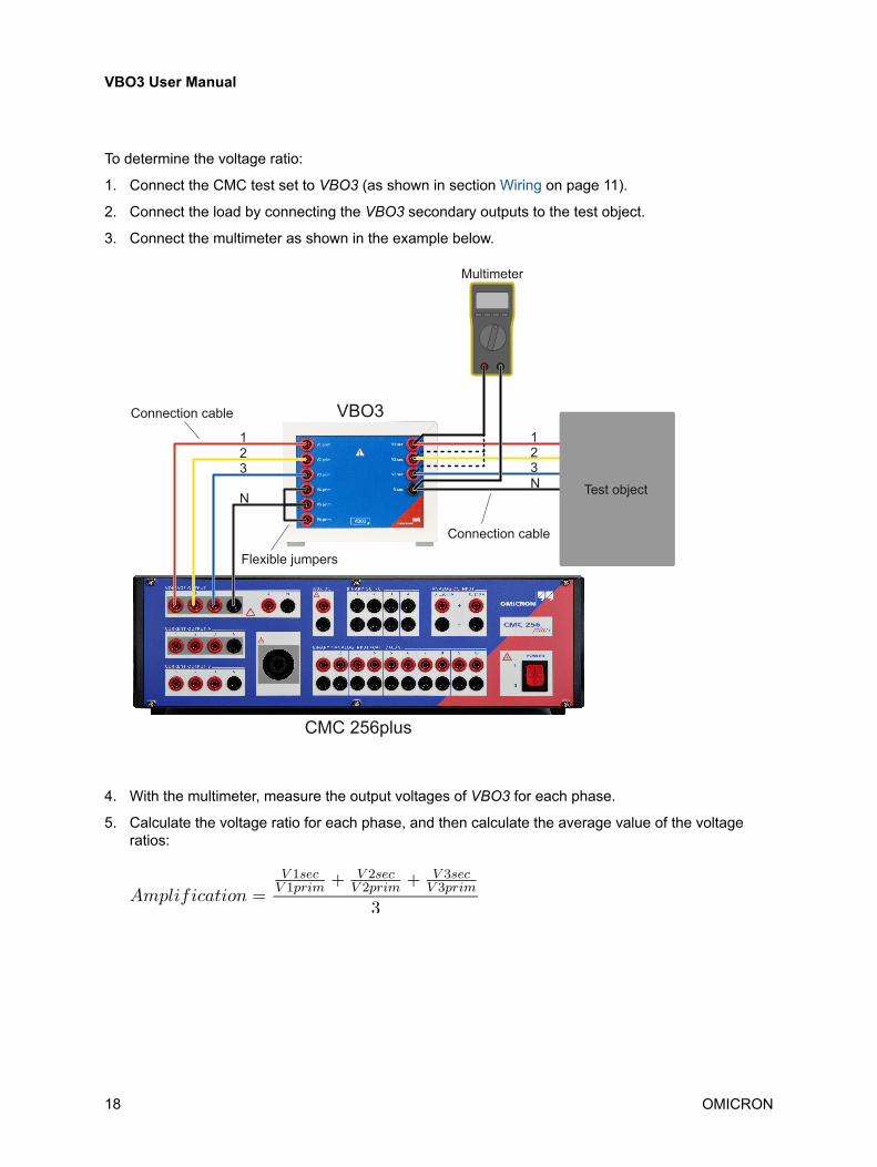
To determine the voltage ratio:
1. Connect the CMC test set to VBO3 (as shown in section Wiring on page 11).
2. Connect the load by connecting the VBO3 secondary outputs to the test object.
3. Connect the multimeter as shown in the example below.
Connection cable
Test object
Flexible jumpers
Connection cable
123N
123
N
Multimeter
VBO3
CMC 256plus
4. With the multimeter, measure the output voltages of VBO3 for each phase.
5. Calculate the voltage ratio for each phase, and then calculate the average value of the voltageratios:
VBO3 User Manual
18 OMICRON

6. In Test Universe, go to the Output Configuration Details dialog (→ page 15), click theConnect VT button, and enter the average ratio in the Amplification field.
Configuring VBO3 in the control software
OMICRON 19

7 Setup with OMICRON transport caseIf you are using VBO3 in combination with a CMC 430, you can create a joint test setup with bothdevices in an OMICRON transport case. Simply detach VBO3's handle to conveniently use the voltagetransformer without needing to take it out of the transport case.
Example:
To detach the handle:
1. Remove the two grey cover caps on both sides of the Aluminium handle.
2. Remove the aluminium handle by loosening the screws.
3. Bring the two levers into a 45° position and remove them.
4. Remove the two fasteners on the left and on the right.
NOTICEEquipment damage possible.
► Do not use the OMICRON transport case for transporting the VBO3 voltage transformer. TheOMICRON transport case does not offer sufficient protection against transport damage forVBO3 voltage transformers.
VBO3 User Manual
20 OMICRON
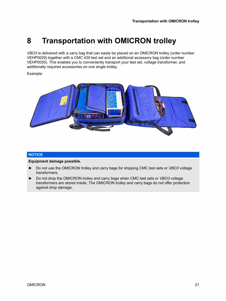
8 Transportation with OMICRON trolleyVBO3 is delivered with a carry bag that can easily be placed on an OMICRON trolley (order numberVEHP0029) together with a CMC 430 test set and an additional accessory bag (order numberVEHP0030). This enables you to conveniently transport your test set, voltage transformer, andadditionally required accessories on one single trolley.
Example:
NOTICEEquipment damage possible.
► Do not use the OMICRON trolley and carry bags for shipping CMC test sets or VBO3 voltagetransformers.
► Do not drop the OMICRON trolley and carry bags when CMC test sets or VBO3 voltagetransformers are stored inside. The OMICRON trolley and carry bags do not offer protectionagainst drop damage.
Transportation with OMICRON trolley
OMICRON 21

9 Technical dataGeneral
Characteristic SpecificationVoltage range primary 0 … 300 V, 3-phaseVoltage range secondary 0 … 600 V, 3-phaseNominal frequency 50/60 HzNominal power 33 VA per phaseProtection class of VBO3 voltage transformer II (for CAT III / 300 V , CAT II / 600 V)Measurement category for VBO3 cables CAT III / 300V , CAT II / 600 V
Environmental conditions
Characteristic SpecificationTemperature
Operating
Storage and transportation
- 25 °C … + 50 °C ( - 13 °F … + 122 °F)
- 40 °C … + 70 °C (- 40 °F … + 158 °F)Maximum altitude
Operating
Storage
4,000 m (13,000 ft)
15,000 m (49,000 ft)Humidity 5 % ... 95 % relative humidity; no condensation
Mechanical data
Characteristic SpecificationWeight (mass) 6.3 kg (13.9 lb)Dimensions without handle (w x h x d) 160 mm x 125 mm x 260 mm
(6.30 " x 4.92 " x 10.24 ")
Standards
SafetyInternational/Europe IEC/EN 61010-1, IEC/EN 61010-2-030USA UL 61010-1, UL 61010-2-030Canada CAN/CSA-C22.2 No. 61010-1,
CAN/CSA-C22.2 No. 61010-2-030
VBO3 User Manual
22 OMICRON

SupportWhen you are working with our products we want to provide you with the greatest possible benefits. Ifyou need any support, we are here to assist you!
24/7 Technical support - get support
www.omicronenergy.com/support
At our technical support hotline, you can reach well-educated technicians for allof your questions. Around the clock – competent and free of charge.
Make use of our 24/7 international technical support hotline:
Americas: +1 713 830-4660 or +1 800-OMICRONAsia-Pacific: +852 3767 5500Europe / Middle East / Africa: +43 59495 4444
Additionally, you can find the OMICRON Service Center or OMICRON SalesPartner closest to you at www.omicronenergy.com
Customer Portal - stay informed
www.omicronenergy.com/customer
The Customer Portal on our website is an international knowledge exchangeplatform. Download the latest software updates for all products and share yourown experiences in our user forum.
Browse through the Knowledge Library and find application notes, conferencepapers, articles about daily working experiences, user manuals and much more.
OMICRON Academy - learn more
www.omicronenergy.com/academy
Learn more about your product in one of the training courses offered by theOMICRON Academy.
OMICRON electronics GmbH, Oberes Ried 1, 6833 Klaus, Austria. +43 59495.
Support
OMICRON 23

VBO3 User Manual
24 OMICRON

ENU 1210 05 02