vd4 36kv manual eng
TRANSCRIPT

1
Instruction manual VD4BA 442/01 E Vacuum circuit-breaker
on withdrawable part36 kV, … 3150 A, ... 31.5 kA40.5 kV, … 3150 A, ... 31.5 kA
ABB Calor Emag Schaltanlagen AG

2

3
Your safety first – always!
• Only install switchgear and/or switchboards in enclosed rooms suitable forelectrical equipment.
• Ensure that installation, operation and maintenance are carried out byspecialist electricians only.
• Comply in full with the legally recognized standards (DIN VDE / IEC), theconnection conditions of the local electrical utility and the applicable safetyat work regulations.
• Observe the relevant information in the instruction manual for all actionsinvolving switchgear and switchboards.
• Danger!
Pay special attention to the hazard notes in the instruction manual marked withthis warning symbol.
• Make sure that under operation condition of the switchgear or switchboardthe specified data are not exceeded.
• Keep the instruction manual accessible to all persons concerned withinstallation, operation and maintenance.
• The user’s personnel are to act responsibly in all matters affecting safety atwork and the correct handling of the switchgear.
If you have any further questions on this instruction manual, the members of ourfield organization will be pleased to provide the required information.
That's why our instruction manual begins with these recommendations:
WARNUNGAnerkannte Regeln der Technik und Betriebsanleitungen
beachten !
Gefährliche Spannung kann elektrischen Schock und Verbrennungen verursachen.
Vor Aufnahme von Arbeiten jeder Art dieses Gerät unbedingt freischalten,erden und kurzschließen.
WARNINGAlways observe the instruction manual and follow the rules
of good engineering practice !
Hazardous voltage can cause electrical shock and burns.
Disconnect power, then earth and short-circuit before proceedingwith any work on this equipment.

4
Contents Page
1 Summary 5
1.1 General 5
1.2 Standards and specifications 5
1.2.1 Switchgear manufacture 5
1.2.2 Installation and operation 5
1.3 Operating conditions 5
1.3.1 Normal operating conditions 5
1.3.2 Special operating conditions 5
2 Technical data 6
2.1 Technical data 6circuit-breakers
2.2 Technical data 8releases and blocking magnet
2.3 Technical data 8motor-operated mechanisms
2.4 Permissible number of vacuum 8interrupter switching operations inrelation to breaking current
2.5 Dimensions 8
3 Structure and function 10
3.1 Structure of the breaker poles 10
3.2 Structure of the breaker operating 10mechanism
3.2.1 Releases, blocking magnet 10and auxiliary switches
3.3 Function 11
3.3.1 Charging of the spring energy store 11
3.3.2 Closing procedure 11
3.3.3 Opening procedure 11
3.3.4 Autoreclosing sequence 11
3.3.5 Quenching principle of the 11vacuum interrupter
4 Despatch and storage 14
4.1 Condition on delivery 14
4.2 Packaging 14
4.3 Transport 14
4.4 Delivery 14
4.5 Intermediate storage 14
Contents Page
5 Installation 16
6 Commissioning/Operation 16
6.1 Note on safety at work 16
6.2 Preparatory activities 16
6.3 Operation of the circuit-breaker 17
6.3.1 Charging the spring energy store 17
6.3.2 Closing and opening 17
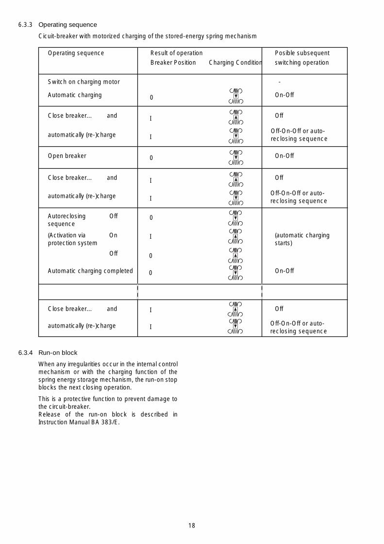
6.3.3 Operating sequence 18
6.3.4 Run-on block 18
7 Maintenance 21
7.1 General 21
7.2 Inspection and functional testing 21
7.2.1 Switching devices in general 21
7.2.2 Stored-energy spring mechanism 21
7.2.3 Checking auxiliary switch settings 21on withdrawable part
7.2.4 Testing of interlock conditions 22
7.2.5 Breaker pole 22
7.3 Servicing 23
7.3.1 Switching devices in general 23
7.3.2 Stored-energy spring mechanism 23
7.3.3 Breaker pole 23
7.4 Repair 24
7.4.1 Replacement of circuit-breaker parts 24and accessories
7.4.2 Replacement of the isolating 24contact systems
7.4.3 Touch up of surfaces 24
7.5 Spare parts and auxiliary materials 24
7.5.1 Spare parts 24
7.5.2 Auxiliary materials 25
8 Application of the 30X-ray regulations
We reserve all rights to this publication. Misuse, particularly including duplication and making available of this manual –or extracts – to third parties is prohibited. The information supplied is without liability. Subject to alteration.
© ABB Calor Emag Schaltanlagen AG, 1998

5
1 Summary
1.1 General
The vacuum circuit-breakers of type VD4 on with-drawable parts for 36 kV or 40.5 kV rated voltageare intended for indoor installation in air-insulatedswitchgear systems. Their switching capacity issufficient to handle any conditions arising fromswitching of equipment and system componentsunder normal operating and fault conditions,particularly short-circuits, within the parameters oftheir technical data.
Vacuum circuit-breakers have particular ad-vantages for use in networks where there is a highswitching frequency in the working current rangeand/or where a certain number of short-circuitbreaking operations are expected. Type VD4vacuum circuit-breakers are suitable for auto-reclosing, and have exceptionally high operatingreliability and long life.
The vacuum circuit-breakers designed in columnform, are supplied as withdrawable modules. Theirbasic structure is shown in figures 3/1 and 3/2.
1.2 Standards and specifications
1.2.1 Switchgear manufacture
The switchgear complies with the followingspecifications in accordance with DIN VDE and therelevant IEC publications respectively:
• DIN VDE 0670, part 1000/IEC 60694.
1.2.2 Installation and operation
The relevant specifications are to be taken intoaccount during installation and operation, particu-larly:
• DIN VDE 0101, erection of power installationswith rated voltages over 1 kV
• DIN VDE 0105, operation of power installations
• DIN VDE 0141, earthing systems for powerinstallations with rated voltages over 1 kV
• Accident prevention regulations issued by theappropriate professional bodies or comparableorganisations.
In Germany, these comprise the following safetyregulations:
– Health and Safety at Work Standard VBG 1
– Health and Safety at Work Standard VBG 4
• Safety guidelines for auxiliary and operatingmaterials
• Order related details provided byABB Calor Emag Schaltanlagen AG.
1.3 Operating conditions
1.3.1 Normal operating conditions
Design to DIN VDE 0670, part 1000, "AC switch-gear for voltages above 1 kV"/IEC publication60694, with the following limit values:
• Ambient temperature:
– Maximum:
•• Rated current 1250 A + 55 °C
•• Rated current 1600 A + 40 °C
•• Rated current 2000 A + 40 °C
•• Rated current 2000 A(ventilation) + 55 °C
•• Rated current 2500 A(ventilation) + 40 °C
•• Rated current 2500 A(forced cooling) + 55 °C
•• Rated current 3150 A(forced cooling) + 40 °C
– Minimum (according to"minus 5 indoor class") – 5 °C
• Humidity:
– Highest mean value measuredover 24 hours 95 %
– Highest mean value measuredover 1 month 90 %
• Maximum site altitude:
≤ 1000 m above sea level.
1.3.2 Special operating conditions
Special operating conditions are to be agreed onby the manufacturer and user. The manufacturermust be consulted in advance about each specialoperating condition:
• Site altitude over 1000 m:
– Allow for the reduction in the dielectricstrength of the air.
• Increased ambient temperature:
– Current carrying capacity is reduced.
– Provide additional ventilation for heatdissipation.
• Climate:
– Avoid the risk of corrosion or other damagein areas:
•• with high humidity and/or
•• with major rapid temperature fluctuations.
– Implement preventive measures (e.g. electricheaters) to preclude condensation pheno-mena.

6
2 Technical data
2.1 Technical datacircuit-breakers
Rated voltage kV 36 40.5
Rated frequency Hz 50/60 50/60
Rated lightning impulse withstand voltage kV 170 200Rated power frequency withstand voltage kV 70 80
Rate of rise of transient recovery voltage kV/µs 0.57 0.69
Peak of transient recovery voltage kV 62 70
Rated operating sequence O-3min-CO-3min-CORated operating sequence with autoreclosing O-0.3s-CO-3min-CO
Guideline values for function times:Closing time approx. 65 ms
Opening time ≤ 45 ms
Arcing time (at 50 Hz) ≤ 15 ms
Total opening time ≤ 60 msMinimum command time on closing 20 ms 2) 120 ms 3)
Minimum command time on opening 20 ms 2) 80 ms 3)
1) When the operating voltage is lower than the rated voltage, the same values apply as for rated voltage.Higher values on request.
2) At the rated auxiliary voltage.3) If the activating relay contact cannot itself interrupt the release coil current.
Breaker Rated Rated Rated Short-circuit Rated Rated Pole Weighttype voltage current short-circuit breaking short-circuit short- centres
breaking current making circuitcurrent asymmet- current durationsymmetrical1) rical1) (peak)1)
VD4 kV A kA kA kA s mm ca. kg
3612-25 36 1250 25 27.3 63 3 280 2903616-25 1600 2903620-25 2000 3403625-25 2500 3403631-25 3150 350
3612-31 36 1250 31.5 34.3 80 3 280 2903616-31 1600 2903620-31 2000 3403625-31 2500 3403631-31 3150 350
4012-25 40.5 1250 25 27.3 63 3 280 2904016-25 1600 2904020-25 2000 3404025-25 2500 3404031-25 3150 3504012-31 40.5 1250 31.5 34.3 80 3 280 2904016-31 1600 2904020-31 2000 3404025-31 2500 3404031-31 3150 350

7
Rated current of the circuit-breaker according to ambient temperature
Circuit- A Ambient Ambient Without With Withbreaker temperature temperature ventilation natural forcedtype 40°C 55°C ventilation ventilation
VD4 1250 x x1600 x x1600 x x2000 x x2000 x x2500 x x2500 x x3150 x x
8
2.2 Technical dataReleases and blocking magnet
Equipment Power consumption1)
AC DC
VA W
Shunt release OFF Y2 3), Y9 3) 250 250Y2 5), Y9 5) 310 310
Shunt release ON Y3 3) 250 250Y3 5) 310 310
Blocking magnet Y1 3) 5) 10 10Undervoltage release Y4• undelayed 3) 5) 11 10• delayed 4) 10 -
Indirect overcurrent release Y7with intermediate current transformer• two-phase 3.5 2) /15 -• three-phase 2.0 2) /15 -
1) Approximate values2) With short-circuited intermediate current transformer3) Auxiliary voltages AC: 110 and 220 V, DC: 24, 48, 60, 110 and 220 V.4) See RN3U for supply voltage5) Auxiliary voltage AC: 240 V, DC: 125 and 240 V.
2.4 Permissible number of vacuum interrupter switching operations in relation to breaking current
See figure 2/1.
2.5 Dimensions
See figure 2/2.
2.3 Technical dataMotor-operated mechanisms
Auxiliary Power Motor protection Charging timevoltage consumption 1) (ABB-Stotz m.c.b.) (maximum) 2)
V VA/W A s
AC110 150 1.6 S 281 UC-K 15220 150 0.75 15240 170 0.75 15
DC 24 130 4.0 S 282 UC-K 15 48 130 3.0 15 60 130 2.0 15110 140 1.0 15125 160 1.0 15220 140 0.75 15240 150 0.75 15
1) Approximate values2) At the rated auxiliary voltage

9
Figure 2/2: Main Dimensions
Circuit-breaker type VD4, 36 kV and 40.5 kVRated short-circuit breaking current 25 kA and 31.5 kA
Figure 2/1: Permissible number of vacuum interrupter operatingcycles n as a function of the breaking current IaBreaking current I (kA)a
10 8 8
6
4
3
2
10 5
8
6
4
3
2
4
10 8 8
6
4
3
2
3
10 8
6
4
3
2
2
10
8
6 5
0,05 0,1 0,2 0,3 0,4 0,6 0,8 1 2 3 4 6 8 10 20 30 40 60
Num
ber
of o
pera
tions
n
1250 A1600 A2000 A
Ratedcurrent
2500 A / 3150 A
708
TP
840
760895
280 280
25K
60
TK
ø69
ø35
TP
260426
900
328
430
40
1379
545
485
1575
900
328
ø79
ø11
3
170
a) Contact arms for 1250 A and 1600 A
TK Transport bracket 147TP Transport profile 148K Entrance for control cables
b) Contact arms for 2000 A to 3150 Awith fan for 2500 A to 3150 A
170 Fan
Note:Transport bracket TK and transport profile TP only fitted for handling.Remove and store prior to commissioning.
10
3 Structure and function
3.1 Structure of the breaker poles
(Figures 3/1, 3/2 und 3/6)
The 36 kV and 40.5 kV circuit-breakers of type VD4are designed as withdrawable units.
The poles, which are constructed in column form,are mounted on a torsionally rigid enclosure sub-structure with rollers. The live parts of the breakerpoles are located in the insulating material poletubes 57.8 and protected from impacts and otherexternal influences.
With the breaker closed, the current path leadsfrom the upper contact arm 57.1 and a chamberholder fixed in the pole tube to the fixed contact58.2 in the vacuum interrupter 58, then via themoving contact 58.3 and roller contact to thelower contact arm 57.2. The switching motion iseffected by means of the insulated coupling rodwith internal contact force springs.
The basic structure of a vacuum interrupter isexplained in figure 3/6.
3.2 Structure of the breaker operating mechanism
(Figures 3/3, 3/4, 6/1 to 6/5, 7/5 to 7/8)
The operating mechanism located in the housingsubstructure is of the stored-energy spring typeand acts on the three breaker poles. The necessaryoperating energy is stored ready for activation bycharging the spring energy storage mechanism.
The stored-energy spring mechanism essentiallyconsists of drum 55.33 containing the spiral spring,the charging system, the latching and operatingmechanism and the linkages which transmit theforce to the breaker poles. In addition, there aresupplementary components such as the chargingmotor, releases, auxiliary switches and the controlsand instruments.
The operating mechanism is fundamentally suitablefor autoreclosing and, due to the short chargingtimes, also for multi-shot autoreclosing.
The operating mechanism is normally fitted with acharging motor. There is also a facility for chargingthe stored energy spring manually.
There is one rating plate 55.7 with the main data ofthe switch equipment on front cover plate left handside 50.7, and another on breaker mechanismhousing.
The basic version of the stored-energy springmechnism is fitted with the following auxiliaryequipment:
• Shunt release OFF Y2
• Five-pole auxiliary switch S4 for annunciationpurposes
• Auxiliary switch S7 for fault annunciation
• ON-OFF operating shaft 54
• Mechanical switch position indicator 55.4
• Charging condition indicator 55.8 for the springenergy store
• Mechanical operating cycle counter 55.5.
The following additional equipment can beinstalled:
• Blocking magnet Y0 on withdrawable part
• Blocking magnet Y1 with auxiliary switch S2
• Shunt release ON Y3
• Second shunt release OFF Y9
• Indirect overcurrent release Y7
• Undervoltage release Y4
• Five-pole auxiliary switches S3 and S5
• Charging motor M0
• Five-pole auxiliary switch S1 to switch thecharging motor
• Anti-pumping relay K0.
3.2.1 Releases, blocking magnet and auxiliary switches
(Figures 3/3, 6/2, 7/7 and 7/8)
The releases and the blocking magnet aremounted at the bottom of the stored-energy springmechanism.
The allocation of the auxiliary switches can be seenin the wiring diagram of figure 7/8.
The five-pole auxiliary switch S1 is operated by thecharging condition indicator 55.8. It controls thecharging motor M0, serves as an electrical interlockfor shunt release ON Y3 when the spring energystorage mechanism is not sufficiently charged, andalso provides an electrical switching readinesssignal.
Operation of the five-pole auxiliary switches S3, S4and S5 is dependent on the switching position ofthe circuit-breaker.
Auxiliary switch S3 interrupts the circuit of the op-tional additional shunt release OFF Y9 with thecircuit-breaker in the open position, and the circuitsof shunt release ON Y3 and the optional blockingmagnet Y1 with the circuit-breaker in the closedposition. There is one further NOC for otherpurposes.

11
Auxiliary switch S4 interrupts the circuit of shuntrelease OFF Y2 with the circuit-breaker in the openposition. One further NOC and three NCCs areavailable for annunciation, control and interlockpurposes.
Auxiliary switch S5 can be optionally designed withany possible combination of contacts from fiveNOCs to five NCCs. Its contacts are available forany required control, annunciation or interlockfunctions. The auxiliary switch is normallyconfigured as shown in figure 7/8.
The single pole auxiliary switch S7 (fleeting contacttime ≥ 30 ms) serves to provide a fault signal("breaker released"). With remote control, theauxiliary switch is necessarily operated via:
• Shunt release OFF Y2 or
• Shunt release OFF Y9 or
• Undervoltage release Y4 or
• Indirect overcurrent release Y7.
Note:
1. Shunt releases OFF (Y2) and ON (Y3) areexclusively provided for opening and closing innormal operation. For safety breakingoperations, the second shunt release OFF (Y9)must be used, in most cases with a separatecontrol voltage supply.
These three releases are of the solenoid typeand suitable for a large number of operatingcycles.
2. The undervoltage release (Y4) and/or indirectovercurrent release (Y7) are pure safety andprotection releases and must not be used forswitching in normal operation.
3.3 Function
3.3.1 Charging of the spring energy store
(Figures 3/3, 6/2, 6/6 and 7/8)
To provide the necessary motive energy, the springenergy storage mechanism is charged via chain55.34 fitted with ratchet wheel 55.35, eitherautomatically by a charging motor or by hand in avertical pumping action with charging lever 128.The current charging condition is shown atcharging condition indicator 55.8
As a precondition for an autoreclosing sequence,the operating mechanism is either (re-)chargedafter a closing operation automatically by thecharging motor, or it requires (re-)charging by handif the operating mechanism is of the manual type.
3.3.2 Closing procedure
(Figures 3/4, 3/6, 6/1, 6/3 and 7/7)
The closing process is initiated manually by thedouble bit key 145 and the ON-OFF operating shaft54, or electrically by activation of shunt release Y3.The release mechanism then permits drive shaft 55.30to be rotated by the (previously) charged spiral spring.The moving contact 58.3 in vacuum interrupter 58 ismoved until the contacts touch by cam disk and furtherkinematic links. In the further sequence of motion,spring arrangement is tensioned and the appropriateamount of contact force thus applied. The availableovertravel is higher than the maximum value ofcontact erosion during lifetime of the interrupter.During the closing process, opening springs aresimultaneously tensioned.
3.3.3 Opening procedure
(Figures 3/3, 3/6, 6/3 and 7/7)
The opening procedure is initiated manually by thedouble bit key 145 and the ON-OFF operating shaft54, or electrically by activation of one of thereleases Y2, Y4, Y7 or Y9. Observe the notes insection 3.2.1 on controlof the releases. Releasemechanism then permits drive shaft 55.30 to beturned further by the spring energy storagemechanism, which is still sufficiently charged. Theopening spring, which is thus released, moves thecontact 58.3 into the open position at a defined speed.
3.3.4 Autoreclosing sequence
An OFF-ON or OFF-ON-OFF autoreclosing se-quence is activated and checked by the protectionsystem. It is necessary for the spiral spring in theoperating mechanism to be in the (re-)chargedcondition, with the circuit-breaker in the closedposition. The (re-)charging process is carried outautomatically after closing of the breaker onbreakers with motor charging mechanisms, butmust be carried out manually on breakers withoutcharging motors (or when the charging motor hasbroken down). Opening of the breaker is alsopossible during the (re-)charging process, but sub-sequent closing of the breaker is however blockeduntil the charging process has been completed.
3.3.5 Quenching principle of the vacuum interrupter
Due to the extremely low static interrupter chamberpressure of 10-4 to 10-8 mbar, only a relatively smallcontact gap is required to achieve a high dielectricstrength. The arc is extinguished on one of the firstnatural current zeros.
Due to the small contact gap and the high con-ductivity of the metal vapour plasma, the arc dropvoltage, and additionally, due to the short arcingtime, the associated arc energy, are extremely low,which has advantageous effects on the life of thecontacts and thus on that of the vacuuminterrupters.
12
Figure 3/1: Withdrawable part with circuit-breaker, type VD4,operator's side
Figure 3/2: Withdrawable part with circuit-breaker, type VD4,pole side
50.1 Earthing contact50.2 Front partition plate50.8 Wheel57.1 Upper contact arm57.2 Lower contact arm57.4 Pole tube caps57.5 Transport plugs (not seen on the picture)57.8 Insulating material pole tube
Figure 3/3: Withdrawable part with circuit-breaker, type VD4,controls for the circuit-breaker
54 ON-OFF operating shaft54.1 Link rod55.4 Switch position indicator55.5 Operating cycle counter55.6 Socket for charging lever55.7 Rating plate55.8 Charging condition indicator
50.2
57.5
57.4
57.1
57.8
57.2
50.1
50.8
54
54.1
55.8
55.6
55.5
55.4
55.7
13
Figure 3/6: Partial section of a vacuum interrupter 58, simplifiedschematic diagram, details vary according to thespecified switching duties.
58 Vacuum interrupter58.1 Insulator58.2 Fixed contact58.3 Moving contact58.4 Metal bellows58.5 Screen58.6 Guide cylinder58.7 Lid
Figure 3/4: Withdrawable part with circuit-breaker, type VD4,left and operator's side view
50 Frame of the withdrawable part50.3 Actuating pin50.4 Guide cam51 Interlock yoke51.1 Catch pin, (spring-loaded)51.2 Sliding handle147 Transport bracket148 Transport profile
Figure 3/5: Withdrawable part with circuit-breaker, type VD4,(pole side, below)
50.1 Earthing contact50.3 Actuating pin (hinged shutters)50.4 Guide cam
50.1
50.4
50.3
51
51.1
147
50
50.4
50.3
148
51.2
58.1
58.2
58.458.5
58.658.7
58.3

14
4.4 Delivery
The duties of the consignee on receipt of theswitching devices at site include the following:
• Checking the delivery for completeness andfreedom from damage (e.g. moisture and itsadverse effects).
• Any short quantities, defects or damage intransit:
– Must be precisely documented on theconsignment note.
– The shipper/carrier is to be notifiedimmediately in accordance with the liabilityprovisions of the German general conditionsfor forwarders (ADSp/KVO)
Note:
Always take photographs to document any majordamage.
4.5 Intermediate storage
Intermediate storage of the circuit-breaker unit inthe switch position OFF and the stored-energyspring mechanisms discharged
(Indicator DISCHARGED: ).
Conditions for optimum intermediate storage:
1. Devices with basic packaging or unpacked:
• A dry and well ventilated storeroom withclimate in accordance with DIN VDE 0670,part 1000/IEC 60694.
• Room temperature which does not fall below–5 °C.
• Do not remove or damage the packaging.
• Unpackaged devices:
– Are to be loosely covered with protectivesheeting.
– Sufficient air circulation must bemaintained.
• Check regularly for any condensation.
2. Devices with seaworthy or similar packagingwith internal protective sheeting:
• Store the transport units:
– protected from the weather,
– dry,
– safe from damage.
• Check the packaging for damage.
• Check the drying agent (see also section 4.2):
– on arrival of the consignment,
– subsequently at appropriate intervals.
• If the maximum storage period starting fromthe date of packaging has been exceeded:
– The protective function of the packaging isno longer guaranteed.
– Suitable action must be taken if inter-mediate storage is to continue.
4 Dispatch and storage4.1 Condition on delivery
• The factory-assembled circuit-breakers on with-drawable parts are checked at the works forcompleteness of the equipment installed andsimultaneously subjected to a routine test inaccordance with DIN VDE 0670, part 1000or IEC publication 60694, thus verifying theircorrect structure and function.
4.2 Packaging
The circuit-breakers on withdrawable parts aremounted individually on wooden pallets and sealed infilm and/or packed in cardboard for delivery.
Packaging for overseas shipment:
• Drying agent bags inserted in the film-sealedpackaging.
• See instructions for use of the drying agent bagsin accordance with DIN 55 473:
– If colour indicator is blue: contents dry,
– If colour indicator is pink: contents moist(e.g. relative humidity above 40 %).
4.3 Transport
(Figures 3/2, 3/4, 4/1 and 7/6)
Loading of the package units must only be carriedout with a
• crane,
• fork-lift truck and/or
• trolley jack.
Notes:
• Avoid impact during handling.
• Do not subject to other damaging mechanicalstresses.
• Lifting gear must not be attached to the breakerpoles or parts of the operating mechanism.
• When moving the withdrawable part only use thesliding handles 51.2 (e.g. for racking in/out thecircuit-breaker unit into/out of the switchgearpanel or for the transport of the unit in theswitchgear room). Do not bring any force on thefront partition plate 50.2 of the withdrawable part.
• Take care that the catch pins 51.1 on the inter-lock yoke 51 are engaged with the guiding rails51.3 in the switchgear when moving in thecircuit-breaker unit into the panel.
• Only handle the modules by crane with bolted-on transport brackets 147, suitable lifting ropesand crane harness.
• Ensure that the circuit-breaker unit on thewithdrawable part, with its relative high situatedcentre of gravity, cannot tip over when moving itby crane or fork lift truck, or when handling itoutside the switchgear room.
• Transport profiles 148 must be screwed on tomove the breaker on rollers 50.8.

15
148147
Figure 4/1: Only handle by crane when the transport brackets and cranecross-beams are fitted. Always bear in mind that the highsituated centre of gravity may induce the breaker to tip over!
147 Transport bracket148 Transport profile
16
6 Commissioning/Operation(Figures: 3/2, 3/3, 6/3 and 6/6)
6.1 Note on safety at work
• The switchgear may only be operated byspecially trained personnel who are familiar withthe characteristics of the particular device.
• Observe the relevant instructions in section 1.2.
6.2 Preparatory activities
(Prior to application of primary voltage)
• Check the circuit-breaker for damage andrestore to the proper conditions wherenecessary.
• Remove any contamination (particularly on theinsulating materials) which has occurred duringtransit, storage or installation.
• Check the primary connections and the earthingcontact 50.1.
• Check the charging motor on circuit-breakerswith motor-operated mechnisms by applyingauxiliary voltage. The stored energy spring ischarged.
• On breakers with manual charging mechanisms,charge the stored energy spring by hand (seeSection 6.3.1).
• Perform a trial opening or closing operation ofthe circuit-breaker using the double bit key 145at the ON-OFF operating shaft 54 (taking intoaccount any required auxiliary voltage and anyrelevant interlocks). Observe switch positionindicator 55.4 and charging condition indicator55.8.
• Remove transport plugs 57.5 from the poles.
• Check that pole tube caps 57.4 are properlyfitted.
• The further procedure results from the inter-action of the truck with the switchgear cubicle.See the Operation Manual for the switchgearts.
• Ensure that the Instruction Manual is available tothe operators at all times.
5 Installation(Figures 3/4 and 4/1)
Perfect operation of the circuit-breaker dependson careful and professional handling of thewithdrawable part.
• Allocate each unit to the appropriate switchgearpanel in accordance with the switchgear planand the rated electrical data.
• Remove the transport profile 148 and transportbrackets 147.
• Insert the withdrawable part in the switchgearpanel checking for unimpeded motion andfunction sequences, including the closing ofprimary (See section 4.3) contacts when theservice position is reached.
• Remove any dirt – see also section 7.3.1.
• For further actions, see Operation Manual for theswitchgear panels.
When the switchgears are operated in areas withhigh humidity and/or major rapid temperaturefluctuations, there is a risk of dew deposits whichmust remain an exception in normal operatingconditions to DIN VDE 0670. Provisions should betaken according to section 1.3.2 (special operatingconditions).

17
6.3 Operation of the circuit-breaker
(Figures 6/1 to 6/3 and 6/6)
6.3.1 Charging the spring energy storage mechanism
Circuit-breakers with charging motors:
• Charging takes place automatically.
• If the charging motor breaks down, the chargingprocess can be carried out or completedmanually.
Circuit-breakers with manual charging mechanisms:
• Insert charging lever 128 into the socket 55.6and pump up and down for approx. 25 strokesuntil the charged condition is displayed.
• When the charged condition is reached, thecharging mechanism automatically disengages,and further strokes of the charging lever have noeffect.
Note:
Charging of the spring energy storage mechanismby hand should only take place when the truck is inthe test/disconnected or removed position.
Key to the charging condition indications:
Discharged Charged
As a precondition for an autoreclosing sequence,the operating mechanism is either (re-)chargedafter a closing operation automatically by thecharging motor, or it requires (re-)charging by handif the operating mechanism is of the manual type.
6.3.2 Closing and opening
• Operate the local or remote electrical controlunit.
• Observe switch position indicator 55.4.
The mechanical control system facilitates manualoperation of the circuit-breaker in the switchgearcubicle even with the door closed:
• Fit double bit key 145 on ON-OFF operatingshaft 54.
• Turn the double bit key approx. 15° clockwieseuntil the stop is reached to close the circuit-breaker, or anti-clockwise to open it.
See also note in section 3.2.1
The operating cycle counter 55.5 is automaticallyincremented by one complete figure with eachswitching cycle. On completion of a switchingoperation the switch position indicator 55.4 in thewindow of front cover plate 50.7. shows theappropriate position of the circuit-breaker.
The anti-pumping relay K0 (wiring diagram infirgure 7/8) prevents repeated ON-OFF switchingoperations if, for example, the breaker is tripped bya protection relay in response to a primary side faultwhile a permanent electrical closing command issimultaneously applied. The circuit-breaker canthen only be closed after the closing command hasbeen interrupted.
18
6.3.3 Operating sequence
Cicuit-breaker with motorized charging of the stored-energy spring mechanism
Operating sequence Result of operation Posible subsequentBreaker Position Charging Condition switching operation
Switch on charging motor -
Automatic charging On-Off
Close breaker... and Off
automatically (re-)charge
Open breaker On-Off
Close breaker... and Off
automatically (re-)charge
Autoreclosing Offsequence
(Activation via On (automatic chargingprotection system starts)
Off
Automatic charging completed On-Off
Close breaker... and Off
automatically (re-)charge
I
I
0
I
I
0
Off-On-Off or auto-reclosing sequence
Off-On-Off or auto-reclosing sequence
I
I Off-On-Off or auto-reclosing sequence
0
0
0
I
6.3.4 Run-on block
When any irregularities occur in the internal controlmechanism or with the charging function of thespring energy storage mechanism, the run-on stopblocks the next closing operation.
This is a protective function to prevent damage tothe circuit-breaker.Release of the run-on block is described inInstruction Manual BA 383/E.

19
Figure 6/1: Withdrawable part with circuit-breaker, type VD4,control area
50 Frame of the withdrawable part50.4 Guide cam50.6 Cover plate, right hand side50.7 Cover plate, left hand side51 Interlock yoke51.1 Catch pin, (spring loaded)51.2 Sliding handle52 Spindle54.1 Link rod55.4 Switch position indicator55.5 Operating cycle counter55.7 Rating plate
Figure 6/2: Changing the store-energy spring mechanism manuallyby moving the inserted charging lever up and down
55.6 Socket for charging lever55.8 Charging condition indicator128 Charging lever
51.1 51.2 51 52 54.1
50 50.4 50.7 55.7 55.4 55.5 50.6
55.8
55.6
128

20
Figure 6/3: Manual operation of the circuit-breaker, by turning thedouble bit key approx. 15° clockwise (ON), or approx. 15°anti-clockwise (OFF)
54 ON-OFF operating shaft145 Double bit key (ON-OFF operation)
Figure 6/4: Fitting the hand crank (against spring-loadedintermediate plate) to move the withdrawable part insidethe panel clockwise towards the service position, andanti-clockwise from the service position towards the test/disconnected position
52 Spindle52.1 Square spigot146 Hand crank
Figure 6/5: Interlock yoke with sliding handles which will be movedinwards to release the withdrawable part for withdrawingfrom the panel.
51 Interlock yoke51.1 Catch pin, spring loaded51.2 Sliding handle51.4 Blocking shaft (interlocking circuit-breaker and
withdrawable part)
Figure 6/6: Operating accessories
128 Charging lever145 Double bit key (ON-OFF operation)146 Hand crank (for moving of the truck)
54 145 146 52.1 52
51
51.2
51.1
128 145 146
51.4
21
7 MaintenanceMaintenance serves to ensure trouble-freeoperation and achive the longest possibleworking life of the switchgear. In accordance withDIN 31 051 / IEC 61208 it comprises the followingclosely related activities:Inspection: Determination of the actual conditionServicing: Measures to maintain the specified
conditionRepair: Measures to restore the specified
condition.
7.1 General
(Figure 7/5)
Vacuum circuit-breakers are characterized by theirsimple and robust construction. They have a longlife expectancy. Their operating mechanisms havea low maintenance requirement, and theinterrupters are maintenance-free during theirworking life. There is no adverse effect on thevacuum, even from frequent switching of operatingand short-circuit currents.
The servicing intervals and scope are determinedby environmental influences, the switchingsequences and number of short-circuit breakingoperations.
With carefully performed inspections and servicingwork, and under normal operating conditions, thecircuit-breakers, depending on the type, have aservice life of up to 20,000 operating cycles and more.
Note:
The following must be observed for all maintenancework:
• The relevant specifications in section 1.2.2
• Notes on safety at work in section 6.1
• Standards and specifications in the country ofinstallation.
Maintenance work may only be performed by fullytrained personnel, observing all the relevant safetyregulations. It is recommended that ABB CalorEmag after-sales service personnel should becalled in, at least during the performance ofservicing and repair work.
While the work is in progress, all auxiliary voltagesources must also be disconnected and secured toprevent reconnection.
Note:In order to prevent accidents (particularly injuryto hands!) extreme care should be taken duringall repair work on the operating mechanism,especially with front cover plates 50.6 and 50.7removed.The spiral spring in the spring energy stragemechanism, for instance, retains a basic tensionwhich is independent of the charging anddischarging processes during switching, so as toensure correct function. This spring energy can beinadvertently released if work is performedincorrectly on the spring mechanism!
7.2 Inspection and functional testing
7.2.1 Switching devices in general
The proper condition of the switching device is tobe verified by regular inspection.
Under normal operating conditions, testing by aqualified personnel is to be performed at least every4 years (in accordance with VBG 4 standard).
In unusual operating conditions (including adverseclimatic conditions) and/or special environmentalpollutions (e.g. heavy contamination and aggressi-ve atmosphere), inspection may also be necessaryat shorter intervals.
Inspection at fixed intervals may be waived if theswitchgear is permanently monitored by a qualifiedpersonnel.
The checks first and foremost comprise visualexamination for contamination, corrosion, moistureand discharge phenomena.
If an incorrect condition is found, appropriateservicing measures are to initiated.
7.2.2 Stored-energy spring mechanism
(Figures 7/6 and 7/7)
Functional testing of the operating mechanism is tobe performed:
• after 5000 operating cycles or
• during servicing work as set out in 7.2.1.
Prior to functional testing, switch the breaker offand isolate the outgoing feeder.
Note:
Isolate and secure the working area in accordancewith the safety regulations specified by DIN VDE/IEC.
Scope of functional testing:
• Perform several switching operations under noload, above all with circuit-breakers seldomoperated in normal service.
• Switch off the charging motor (if fitted) anddischarge the spring mechanism by ON/OFFswitching operations.
• Examine visual the condition of the lubrication onrotary bearings, sliding surfaces, etc.
• Check the proper mechanical/electrical se-quence of the individual functions.
7.2.3 Checking auxiliary switch settings on with-drawable part
(Figures 6/4, 6/6, 7/6 to 7/8)
Compliance with the interlock conditions in theareas of the test/disconnected position and theservice position is ensured by auxiliary switchesS8 and S9, located in the breaker housing.
22
In test operations, the withdrawable part must bemoved by hand with the crank 146 fitted.
1. Settings in the area of the test/disconnectedposition
• Move the withdrawable part out of the test/disconnected position towards the serviceposition with a few turns of the crank.
• Slowly move the withdrawable part back tothe stop.
Auxiliary switch S8 must then operate whenthe hand crank has a remaining angle of + 60°of turn to reach the stop.
• Slowly insert the withdrawable part from thetest/disconnected position towards theservice position until auxiliary switch S8 justoperates.
In this position, it must still just be possible tomove closing push rod 55.2. For this test, thefunction of the blocking magnet Y0 (if fitted)must be deactivated manually.
This condition ensures that the electricalinterlock takes effect before the mechanicalinterlock in the motion sequence involved.
2. Settings in the area of the service position
• Move the withdrawable part out of the limitposition towards the test/disconnectedposition with a few turns of the crank.
• Slowly move the withdrawable part forwardsagain to the stop:
Auxiliary switch S9 must then operate whenthe hand crank has a remaining angle of + 60°of turn to reach the stop.
7.2.4 Testing of interlock conditions
(Figures 6/4, 6/6, 7/5, 7/6 and 7/8)
The testing procedures for the withdrawable part.
1. The withdrawable part must only be movablefrom the test/disconnected position into theservice position when the circuit-breaker is open.
Check the following conditions individually:
• With the circuit-breaker closed, insertion ofthe withdrawable part towards the serviceposition must be blocked after only half a turnof the crank in the clockwise direction.
• With the earthing switch closed, insertion ofthe withdrawable part towards the serviceposition must be blocked after only twoclockwise turns of the crank.
Do not use force !
2. The withdrawable part must only be movablefrom the service position into the test/disconnected position with the circuit-breakeropen.
Check this condition as follows:
• With the circuit-breaker closed, withdrawalmovement of the withdrawable part must beblocked after only half a turn of the crank inanti-clockwise direction.
3. Closing of the circuit-breaker must only bepossible when the withdrawable part is in thedefined test/disconnected position or serviceposition.
The control wiring plug 10.2 must previouslyhave been inserted.
Check this condition as follows:
• It must not be possible to close the circuit-breaker with the withdrawable part in anyposition between the test/disconnectedposition and the service position.
• Enabling of switching when the withdrawablepart moves into the service position iseffected electrically by operation of auxiliaryswitch S9 in the breaker housing.
• For motion into the test/disconnectedposition, the same enabling conditions applyanalogously, in this case by means of auxiliaryswitch S8 in the breaker housing.
4. It must only be possible to open the circuit-breaker (manually) when the withdrawable partis in the service position or test/disconnectedposition and the control voltage has failed.
Check this condition.
5. Withdrawable parts with order-related blockingmagnet Y0 may not be moved in case of controlpower failure, or when there is no control power.Do not forcibly move blocked withdrawableparts!
Releasing the blocking magnet Y0.
• Remove front cover plates 50.6, 50.7.
• Disengage blocking magnet Y0 by pulling themagnet armature,
• While doing so, turn crank 146 about one halfturn (either direction of rotation is permissible).
The blocking magnet is only active in the testposition and service position. In intermediatepositions it has no effect.
6. Disconnection of the control wiring plug 10.2 aswell later insertion must be blocked in the with-drawable part‘s service position.
Check this condition.
7.2.5 Breaker pole
No inspection of the breaker pole above andbeyond the stipulations of section 7.2.1 isnecessary.

23
7.3 Servicing
7.3.1 Switching devices in general
If cleaning is found to be necessary duringinspections as set out in 7.2.1, the followingprocedure is to be adopted:
• Prior to cleaning, the working area is to beisolated and secured against reclosing wherenecessary in accordance with the safetyregulations of DIN VDE/IEC.
• Cleaning of surfaces in general:
– Dry, lightly adhering dust deposits with a soft,dry cloth.
– More strongly adhering contamination withslightly alkaline household cleanser or RivoltaBWR 210.
• Cleaning of the insulating material surfaces andconductive components:
– Light contamination:with Rivolta BWR 210.
– Strongly adhering contamination:with cold cleanser 716.
Wipe down after cleaning, using clean water,and dry properly.
• Observe the manufacturer's instructions and thespecial ABB instruction manuals Ba 1002/E orBA 1006/E on safety at work.
Note:
Use only halogen free cleansers, and in no case1.1.1-trichlorethane, trichlorethylene or carbontetrachloride!
7.3.2 Stored-energy spring mechanism
Servicing or the spring mechanism is to beperformed after 10,000 operating cycles.
Prior to servicing, switch the breaker off, and isolatethe outgoing feeder.
Observe the safety regulations!
Details of the servicing:
• Swich off the charging motor (if fitted), anddischarge the spring energy storage mechanismby closing and opening the breaker once.
• Replace parts subject to high climatic andmechanical stresses after 10,000 operatingcycles as a precaution (for details see ABB CalorEmag after-sales service).
• For replacing highly stressed parts neutralizebasic tension of the spiral spring, state the rate.Be careful when carrying out!
• Relubricate pawls, support shafts, sliding androtating bearing surfaces. Lubricant: IsoflexTopas NB 52.
• Check the fit of fasteners (e.g. locking pins) incranks, pins, bolts etc. Check the tightness offastening bolts.
• Always replace any spring lock washers, splitpins and other fasteners removed during thework with new parts when reassembling theequipment.
• Check the general condition of the operatingmechanism and recharge the spring energystore.
• Perform comprehensive mechanical andelectrical functional tests.
• Ensure that the bolted joints at the contactlocations of the conductor bar system and theearthing connections are tight.
Note:
This work may only be performed by the after-salesservice personnel of ABB Calor Emag Schaltanla-gen AG or adequately qualified personnel.
7.3.3 Breaker pole
The breaker pole with the vacuum interrupter ismaintenance-free up to reaching the permissiblenumber of vacuum interrupter operating cycles inaccordance with section 2.4.
Checking of the vacuum is only necessary whenthere is good cause to suspect that force appliedexternally to a pole tube has caused damage to thevacuum interrupter inside.
If the pole tube is damaged or destroyed, it may benecessary to replace the complete breaker pole.
The working life of the vacuum interrupter is definedby the sum current limit corresponding to theequipment data in individual cases in accordancewith section 2.4:
• When the sum current limit is reached, thecomplete breaker poles are to be replaced.
• When the permissible number of mechanicaloperating cycles (i.e. the number correspondingto Ia=0 on the characteristic curve) of thevacuum interrupters has been reached, thebreaker poles must be replaced. However, itshould be investigated beforehand as towhether the installation of a new breaker wouldbe more advantageous.
For testing the vacuum without dismantling thecircuit-breaker you may use:
• Vacuum tester VIDAR,from Programma Electric GmbH,Bad Homburg v.d.H.
A test DC voltage of 60 kV is to be set for testing ofthe pressure inside the interrupter chamber withvacuum tester VIDAR.
Testing is to be performed at the rated contactdistance in the OFF condition.

24
7.5 Spare parts and auxiliary materials
7.5.1 Spare parts
Designation Breaker Breaker Rated Rated Part no.1)
type VD4... type VD4... current short-circuit (order code)breaking
Rated Rated currentvoltage voltage symm.
36 kV 40.5 kV A kA
Breaker pole, complete 3612-25 4012-25 1250 25 GCE7002270R01113616-25 4016-25 1600 GCE7002270R01112)
3620-25 4020-25 2000 GCE7002270R01073625-25 4025-25 2500 GCE7002270R01073631-25 4031-25 3150 GCE7002270R01073)
3612-31 4012-31 1250 31.5 GCE7002270R01113616-31 4016-31 1600 GCE7002270R01112)
3620-31 4020-31 2000 GCE7002270R01073625-31 4025-31 2500 GCE7002270R01073631-31 4031-31 3150 GCE7002270R01073)
1) Always quote the serial number of the switch equipment when ordering parts.2) At ambient temperature 55°C use breaker pole ID No.: GCE 7002270R0107.3) Circuit-breaker 3150 A permitted for ambient temperature 40° C only.
Note:
Dismantling and Replacement of the completebreaker poles should only be carried out by ABBCalor Emag after-sales service personnel or byspecially trained personnel, particularly as properadjustment is necessary.
7.4 Repair
7.4.1 Replacement of circuit-breaker parts andaccessories
Only remove and reassemble circuit-breaker partsand accessories when the breaker has beenswitched off and the working area is to be isolatedand secured against reclosing. The spring energystorage mechanism must by discharged.
All auxiliary voltage sources must be disconnectedand secured against reclosing during the removaland installation work.
7.4.2 Replacements of the isolating contact systems
(Figures 7/1 to 7/4)
• Draw the two internal annular tension springs57.6 facing the breaker pole forwards besidethe two external annular tension springs 57.7,and remove the contact system 57.3/57.13thus released from the isolating contact arm.
• Slide a new contact system onto the thin end ofauxiliary arbor 127/130, rear side first.
• Insert the plug 127.1/130.1 on auxiliary arbor127/130 into the relevant isolating contact arm,and slide the contact system 57.3/57.13 overonto the isolating contact arm.
• Check the correct fit of all contact fingers andannular tension springs.
• Grease the isolating contact system with IsoflexTopas NB 52.
Note:
The set position of the isolating contact arms mustnot be changed by the exertion of excessiveforce.
7.4.3 Touch up of surfaces
• Sheet steel parts, painted
– Remove rust, e.g. with a wire brush.
– Grind off paint coat and grease.
– Apply anti-rust primer and top coat.
• Sheet steel parts, with zink surface andpassivated functional parts:
– Remove white rust with a wire brush orcleaning pad (e.g. Scotch-Brite white).
– Remove loosely adhering particles with a drycloth.
– Apply zinc spray or zinc dust primer.
• Functional parts, phosphated:
– Remove rust with a wire brush or cleaningpad (e.g. Scotch-Brite white).
– Clean with a dry cloth.
– Grease with Isoflex Topas NB 52.

25
Designation Item Rated Ident no.no. voltage (order code)
Auxiliary switch S1 GCE7002397R0122
(with clamp-type terminal) S3 GCE7002397R0121S4 GCE7002397R0122
S5 GCE7002397R01..1)
Auxiliary switch on blocking magnet S2 GCE7003022P0101
Auxiliary switch for fault annunciation S7 GCE0905121P0100
1st shunt release OFF Y2 GCE7004590P01..2)
2nd shunt release OFF Y9 GCE7004590P01..2)
Shunt release ON Y3 GCE7004590P01..2)
Blocking magnet Y1 GCE9478103P01..2)
Undervoltage release Y4 GCE9371466R01..2)
with spring mechanism
Delayed undervoltage release Y4 GCE9371466R01..2)
with spring mechanism
Indirect overcurrent release with intermediate Y7 GCE9371466R0112current transformer and spring mechanism
Intermediate current transformer for GCE9476148R0100indirect overcurrent release
Magnet holder, complete GCE7000880R0111(with integrated rectifiers V1, V2, V3, V9)
Series rectifier V4/V7 GCE7004046R0101
Charging motor M0 DC 24 V GCE0940084P0101
DC 48 V GCE0940084P0103
DC 60 V GCE0940084P0104
DC/AC 110 V GCE0940084P0105
DC 125 V GCE0940084P0105
DC/AC 220/240 V GCE0940084P0106
Push-on sleeve 4.8-2.5 DIN 46247 Page 2for push-on blade 0.8 thick(for additional external connections)
(with gearing)
1) Quote contact arrangement2) State the type of release and voltage
7.5.2 Auxiliary materials Ident no.(order code)
Lubricant:
• Isoflex Topas NB 52 GCE0007249P0100
Halogen-free cleanser:
• Rivolta BWR 210 GCE0007707P0100(for general cleaning)
Observe the relevant ABB instruction manual BA1002/E GCEA901002P0102
• Cold cleanser (Kaltreiniger) 716 GCE0007706P0100(use for conductive components, insulating-materialcomponents and for heavy contamination)
Observe the relevant ABB instruction manual BA 1006/E GCEA901006P0102

26
Figure 7/2: Sliding the contact system onto the auxiliary arbour withthe rear end first, schematic representation here for 1600 A
57.3 Contact system, ...1600 A127 Auxiliary arbour, ...1600 A127.1 Plug, ...1600 A
Figure 7/1: Contact system example for 3150 A
• left: front view• right: rear view
Figure 7/3: Contact system shift on auxiliary arbour for 2000 A to 3150 A
57.13 Contact system, 2000 A to 3150 A57.6 Internal annular tension springs57.7 External annular tension springs130 Auxiliar arbour, 2000 A to 3150 A130.1 plug, 2000 A to 3150 A
Figure 7/4: Sliding of the contact system from the auxiliary arbouronto the contact arm and engaging it here.
127.1 127 57.3
130.1 130 57.13 57.6 57.7

27
Figure 7/5: Before moving the front plate, first disconnect the link rod54.1 at the lower point and swing it to one side. Turn thehand crank anti-clockwise first to move the interlock yoke51 an appropriate distance away.
50.6 Cover plate, right hand side50.7 Cover plate, left hand side51 Interlock yoke54 ON-OFF operating shaft54.1 Link rod
Figure 7/6 Auxiliary switches for interlocking withdrawable part andswitchgear panel (withdrawable part in service position)
10 Control wiring plug connector, closed10.1 Control wiring socket10.2 Control wiring plug10.4 S8, limit switch for test position indicator10.5 S9, limit switch for service position indicator51 Interlock yoke51.3 Guiding rail (panel)54 ON-OFF operating shaft
51
54.1
50.6
50.7
10.451.3 10.5
54
51
10
10.210.1
54

28
Figure 7/7: The spring-loaded operating mechanism in the frame ofthe withdrawable part, front cover plates removed
45 Magnet holder, complete54.1 Link rod55.2 ON push rod55.3 OFF push rod55.4 Switch position indicator55.5 Operating cycle counter55.6 Socket for charging lever55.8 Charging condition indicator55.30 Drive shaft55.33 Drum with spiral spring55.34 Chain55.35 Ratchet wheel55.36 Charging motor
55.33
55.8
55.30
55.36
55.6
55.5
55.4
54.1
55.355.2
45
55.35
55.34

29
Figu
re 7
/8:
Wiri
ng d
iagr
am
Arr
ange
men
t for
DC
24,
48,
60,
110
, 125
,22
0, 2
40 V
; AC
110
, 220
, 240
V
Sho
wn
with
the
sprin
g op
erat
ing
mec
hani
sm in
the
disc
harg
ed s
tate
. Th
e w
iring
dia
gram
com
pris
esth
e ba
sic
com
pone
nts
and
all
furt
her
equi
pmen
top
tions
for
the
var
ious
VD
4 ty
pes.
The
sco
pe o
feq
uipm
ent p
ossi
ble
with
in a
n in
divi
dual
type
ser
ies
is l
iste
d in
the
rel
evan
t sw
itchg
ear
list,
and
the
equi
pmen
t fit
ted
in e
ach
indi
vidu
al c
ase
can
befo
und
in th
e or
der
docu
men
tatio
n.
Not
e:
Shu
nt re
leas
es a
nd b
lock
ing
mag
nets
are
fund
amen
-ta
lly w
ired
with
rec
tifie
rs (e
.g. m
agne
t hol
der 4
5 w
ithin
tegr
ated
rec
tifie
rs V
1, V
2, V
3 an
d V9
). R
ectif
iers
func
tion
as fr
ee-w
heel
ing
diod
es is
d.c
.-su
pply
.
26-X
0
45
-S3
21 22 20
-S2
0 231 3213 14
-K0
42
1
-Y3
53 54
-K0-R0
4 14
13 14
43 44 -Y9
2
-Y4
44
-Y2
30
-Y7
-S4
13 14
-S1
22 21
1341
4221
2218
53 54
41 42
31 32
21 22238
1131
3243
53 54
32 31
-M0 M
24
41 42
36-X
034
35155
3
33
27 371 2
-S7
25
-Y1
-Y0 46
13 14
-S5
43 44
53 54
31 32
21 2229 39
289
76
1719
38
1115 54
1658
565557
1049
52
18-X
14
5153
50
16
7-X
94
21
8-X
35
6
1312
17-X
-S8
53 54
43 44
33 34
23 24
13 14
-S9
53 54
43 44
33 34
140
13 14
23 24
OF
F
ON
AE
-V1
-V0
-V3
-V9
-V4
-V2
P
+ -
~~
~~+
-
+-
~~~ ~
+-
--
++
~~
~~
EA
RT
HIN
G S
WIT
CH
ME
CH
AN
ICA
L IN
TE
RLO
CK
WIT
H C
.B.-
UN
IT:
C.B
.-U
NIT
CA
N B
E M
OV
ED
IN T
HE
SE
RV
ICE
PO
SIT
ION
-Y0
BLO
CK
MA
GN
ET
ON
TR
UC
K W
ITH
RE
CT
IFIE
R -
V0
-Y1
CLO
SIN
G B
LOC
K M
AG
NE
T W
ITH
RE
CT
IFIE
R -
V1
-Y3
CLO
SIN
G R
ELE
AS
E W
ITH
RE
CT
IFIE
R -
V3
-Y4
UN
DE
RV
OLT
AG
E R
ELE
AS
E U
< W
ITH
RE
CT
IFIE
R -
V4
-Y9
2.S
HU
NT
RE
LEA
SE
OF
F W
ITH
RE
CT
IFIE
R -
V9
-S3
AU
XIL
IAR
Y S
WIT
CH
ON
SW
ITC
H S
HA
FT
-S4
AU
XIL
IAR
Y S
WIT
CH
ON
SW
ITC
H S
HA
FT
-S5
AU
XIL
IAR
Y S
WIT
CH
ON
SW
ITC
H S
HA
FT
-S7
WIP
ING
CO
NTA
CT
35m
s F
OR
C.B
. TR
IPP
ED
IND
ICA
TIO
N
SE
RV
ICE
-P
OS
ITIO
N
TE
ST-
PO
SIT
ION
-M0
CH
AR
GIN
G M
OT
OR
-S1
AU
XIL
IAR
Y S
WIT
CH
ON
ME
CH
AN
ISM
-S8
LIM
IT S
WIT
CH
TE
ST
PO
SIT
ION
-S9
LIM
IT S
WIT
CH
SE
RV
ICE
PO
SIT
ION
-K0
AN
TIP
UM
PIN
G R
ELA
Y
-S2
AU
XIL
IAR
Y S
WIT
CH
ON
BLO
CK
MA
GN
ET
-Y
1
MO
DE
OF
PR
ES
EN
TAT
ION
:
• C
.B.-
UN
IT IN
TE
ST
PO
SIT
ION
:•
EA
RT
H. S
WIT
CH
OP
EN
PO
SIT
ION
:E
AR
TH
. SW
ITC
H C
AN
BE
OP
ER
AT
ED
-Y7
IND
IRE
CT
OV
ER
CU
RR
EN
T R
ELE
AS
E
-Y2
1.S
HU
NT
RE
LEA
SE
OF
F W
ITH
RE
CT
IFIE
R -
V2
AU
X. S
WIT
CH
-S
1 S
HO
WN
FO
R C
.B.-
ME
CH
AN
ISM
DIS
CH
AR
GE
DC
.B.-
UN
IT IN
SE
RV
ICE
PO
SIT
ION
CO
NT
RO
L W
IRIN
G P
LUG
58
PO
LE

30
8 Application of the X-ray regulationsOne of the physical properties of vacuuminsulations is the possibility of X-ray emissionswhen the contact gap is open. The specified typetest performed by the Physikalisch-TechnischeBundesanstalt (PTB) in Brunswick demonstratesthat the local dosage output of 1 µSv/h at adistance of 10 cm from the touchable surface is notexceeded.
The results are as follows:
• The use of the vacuum interrupters at ratedvoltage is completely safe.
• The application of the rated power frequencywithstand voltage specified for the switchingdevices by DIN VDE 0670 and IEC 60056 isalso safe.
• Higher voltages than the rated power frequencywithstand voltage or DC test voltage specified inDIN VDE or IEC standards must not be applied!
• Fulfilment of the above requirement with thevacuum interrupter in the open position isdependent on maintenance of the specifieddistance between the contacts (which isautomatically ensured with correct mechanismfunction and force transmission).

31

32
Instruction manual No. GCEA 67 0442 P0102Printed in Germany (09.98-500-PPI)
ABB Calor Emag Schaltanlagen AG
Käfertaler Strasse 250 Bahnstrasse 39-47D-68167 Mannheim D-40878 Ratingen
Phone: +49(0)6 21/3 86-27 77, Telefax: +49(0)6 21/3 86-21 93E-Mail: [email protected]: http://www.abb-calor-emag.de
No responsibility is accepted for data and illustrations. We reservethe right to make changes in the course of technical development.
Presented by: