vector controllers for bldc motors state of art technology … · 2016-07-20 · vector controllers...
TRANSCRIPT
MIROMAX, UAB Dūmų 3C, Mob. +370 647 48 600 LT-11119, Vilnius Tel: +370 700 30 154 www.miromax.lt [email protected]
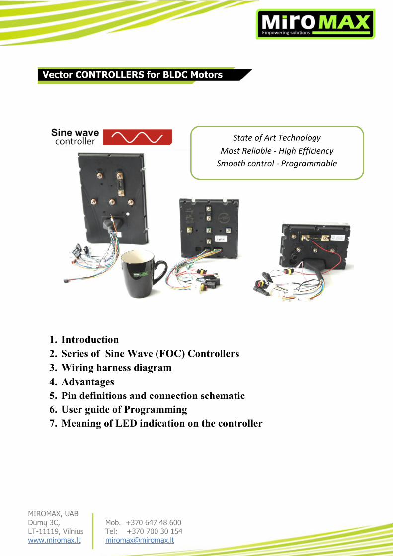
1. Introduction 2. Series of Sine Wave (FOC) Controllers 3. Wiring harness diagram 4. Advantages 5. Pin definitions and connection schematic 6. User guide of Programming 7. Meaning of LED indication on the controller
State of Art Technology Most Reliable - High Efficiency
Smooth control - Programmable
Vector CONTROLLERS for BLDC Motors

MIROMAX, UAB Dūmų 3C, Mob. +370 647 48 600 LT-11119, Vilnius Tel: +370 700 30 154 www.miromax.lt [email protected]
Field-Oriented Control (FOC) is an important technology for motor systems, particularly those using
permanent magnets (PM). In general, FOC provides an efficient way to control BLDC motor in adjustable
speed drive applications that have quickly changing loads, and can improve the power efficiency of an
AC induction motor, especially at lower speeds. For this reason, some designers mistakenly associate
FOC for use only with AC motors. While it is true that today’s brushless DC (BLDC) motors tend to very
efficient, up to 96 percent even without FOC, the value FOC brings to these systems is reduced torque
ripple, resulting in smoother motor performance and quieter operation.
In simple terms, FOC is a motor control technique where the system is trying to orient the stationary or
“stator” flux vector to a specific degree relative to the rotor flux vector (see Figure 1). The optimal degree
of orientation depends upon what characteristic of the motor needs to be maximized. The most common
use of FOC is to maximize the motor’s torque per amp. This is achieved when the stator flux vector is 90
degrees to the rotor flux vector unless the motor has a variable reluctance, such as a motor with a magnet
buried inside it. In this case, the degree of orientation is typically 115 to 120 degrees.
Figure 1: Field-oriented control techniques orient the stator flux vector to a specific degree relative to the rotor flux vector. (Source: Texas Instruments. Used with permission.)
INTRODUCTION

MIROMAX, UAB Dūmų 3C, Mob. +370 647 48 600 LT-11119, Vilnius Tel: +370 700 30 154 www.miromax.lt [email protected]
MiroMax’s offered FOC controller products are specially designed for high power rating brushless dc
(BLDC) motors from 1KW up to 20KW with voltages between 48V and 96V.
The product series use the FOC (Field Oriented Control/Sine Wave)algorithm in which SVPWM is used
to drive the power device so that it injects sinusoidal current to the three-phase of motor. Meanwhile, by
using a 32-bit microprocessor which incorporates the latest ARM core,it exhibits excellent operational
capability. The system handles several close loops which include torque, flux and speed loop and at the
same time other high demand of real-time task operation is possible.
Electric Cars
Electric Bike, Trike, Quad,
Electric Motorcycles, Scooters
Electric Golf , Buggies, Forklifts, ect.
Application in industry
____________________________________________________________________________________
Application

MIROMAX, UAB Dūmų 3C, Mob. +370 647 48 600 LT-11119, Vilnius Tel: +370 700 30 154 www.miromax.lt [email protected]
VEC300 VEC500 VEC700
Model Rated Voltage
Rated Current
Max Phase Current
Dimmension LxWxH (Weight)
170*120x50mm [1.9kg] VEC200-48 48V 100A 200A
VEC200-72 72V 80A 200A VEC300-48 48V 120A 300A
190*180*50mm [2.5kg] VEC300-72 72V 100A 300A VEC300-96 96V 80A 250A VEC500-48 48V 200A 500A
200*190*58mm [3.2kg] VEC500-72 72V 150A 500A VEC500-96 96V 120A 450A VEC700-48 48V 500A 700A
330x225x70mm [6.5kg] VEC700-72 72V 450A 700A VEC700-96 96V 400A 700A VEC700-120 120V by individual order
SINE WAVE (FOC) CONTROLLERS SERIES
State of Art Technology Most Reliable High Efficiency Smooth Control Programmable
MIROMAX, UAB Dūmų 3C, Mob. +370 647 48 600 LT-11119, Vilnius Tel: +370 700 30 154 www.miromax.lt [email protected]
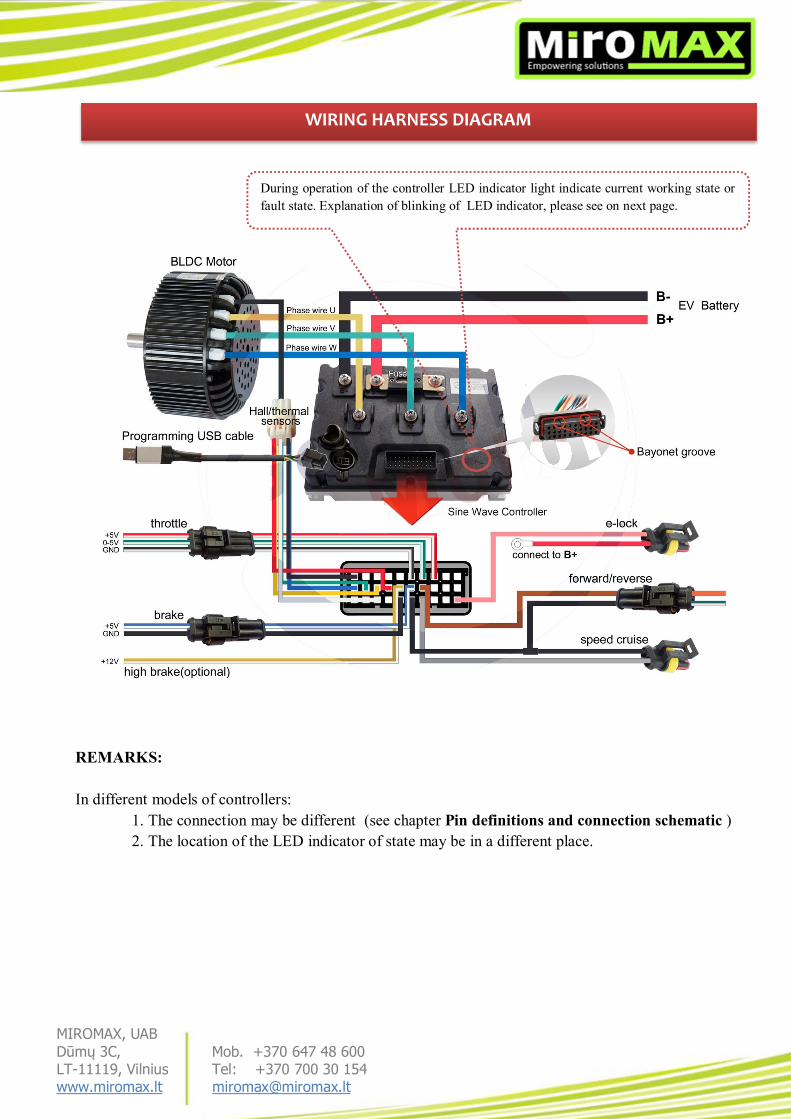
REMARKS: In different models of controllers:
1. The connection may be different (see chapter Pin definitions and connection schematic ) 2. The location of the LED indicator of state may be in a different place.
WIRING HARNESS DIAGRAM
During operation of the controller LED indicator light indicate current working state or fault state. Explanation of blinking of LED indicator, please see on next page.
MIROMAX, UAB Dūmų 3C, Mob. +370 647 48 600 LT-11119, Vilnius Tel: +370 700 30 154 www.miromax.lt [email protected]
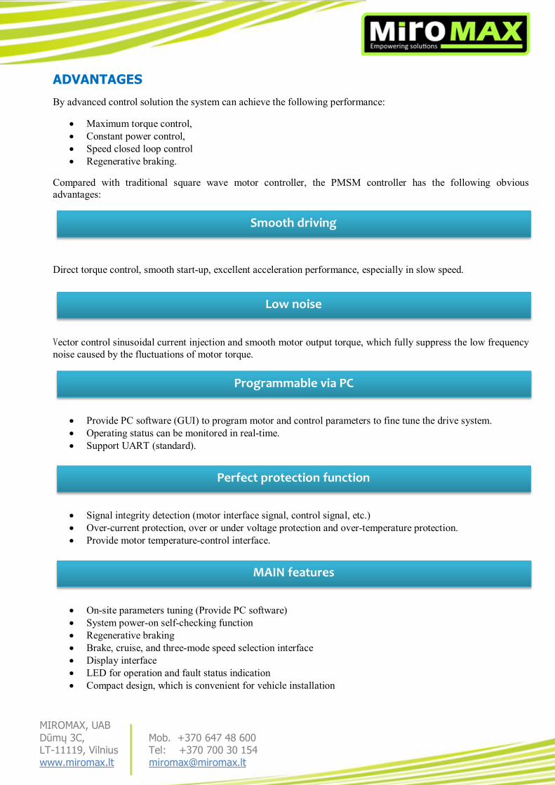
ADVANTAGES
By advanced control solution the system can achieve the following performance:
Maximum torque control, Constant power control, Speed closed loop control Regenerative braking.
Compared with traditional square wave motor controller, the PMSM controller has the following obvious advantages:
Direct torque control, smooth start-up, excellent acceleration performance, especially in slow speed.
Vector control sinusoidal current injection and smooth motor output torque, which fully suppress the low frequency noise caused by the fluctuations of motor torque.
Provide PC software (GUI) to program motor and control parameters to fine tune the drive system. Operating status can be monitored in real-time. Support UART (standard).
Signal integrity detection (motor interface signal, control signal, etc.) Over-current protection, over or under voltage protection and over-temperature protection. Provide motor temperature-control interface.
On-site parameters tuning (Provide PC software) System power-on self-checking function Regenerative braking Brake, cruise, and three-mode speed selection interface Display interface LED for operation and fault status indication Compact design, which is convenient for vehicle installation
Smooth driving
Low noise
Programmable via PC
Perfect protection function
MAIN features

MIROMAX, UAB Dūmų 3C, Mob. +370 647 48 600 LT-11119, Vilnius Tel: +370 700 30 154 www.miromax.lt [email protected]
PIN DEFINITIONS and CONNECTION SCHEMATIC for VEC300
VEC 300
VEC 300

MIROMAX, UAB Dūmų 3C, Mob. +370 647 48 600 LT-11119, Vilnius Tel: +370 700 30 154 www.miromax.lt [email protected]
PIN DEFINITIONS and CONNECTION SCHEMATIC for VEC500
VEC 500
VEC 500

MIROMAX, UAB Dūmų 3C, Mob. +370 647 48 600 LT-11119, Vilnius Tel: +370 700 30 154 www.miromax.lt [email protected]
PIN DEFINITIONS and CONNECTION SCHEMATIC for VEC700
VEC 700
VEC 700

MIROMAX, UAB Dūmų 3C, Mob. +370 647 48 600 LT-11119, Vilnius Tel: +370 700 30 154 www.miromax.lt [email protected]
In order to set up necessary parameters into controller (or change them) we need to do following steps:
1. Download programming software from HERE 2. Install software During the programming power supply of controller has to be TURNED OFF !
3. Connect controller to a PC with USB programming cable. 4. RUN installed software PI-800.
After changing parameters, disconnect USB cable from controller and PC. Now you can test your controller with new settings.
User guide of Programming
During operation of the controller LED light indicate current working state or fault state. Explanation of blinking of LED indicator, please see next page.
In different models of controller The location of the LED indicator of state may be in a different place.
1. Select COM port, which is used for USB cable. (be aware that COM port number can be different that is is shown in a picture).
2. Now press this button. „Connect to Controller“
3. You will see a message that the controller configuration read successfully. To continue
programming, press „OK“ or .
4. After changing parameters press “download” button. Then you will download new settings to your controller.

MIROMAX, UAB Dūmų 3C, Mob. +370 647 48 600 LT-11119, Vilnius Tel: +370 700 30 154 www.miromax.lt [email protected]
During operation of the controller LED indicator light indicate current working state or fault state. Explanation of blinking of LED indicator, please see table below:
System Protection Characteristics LED Blinking Times
Over-voltage protection Battery voltage is higher than default value
1
Under-voltage protection Battery voltage is lower than default value
2
Motor over-current protection
Motor phase is short-circuit or phase to ground is short-circuit
3
Motor over-heat protection
Motor temperature is higher than default value
13
Stalling protection Motor stalling time is over default value
4
HALL protection HALL input is abnormal 5 MOSFET protection MOSFET self-checking is abnormal 6 Phase winding disconnect protection
One of the motor phase is disconnection
7
Self-checking error protection
System internal power-on self-checking is abnormal
10
Controller over-heat protection
When controller operation temperature is higher than default value
11
Throttle protection Throttle input is abnormal 12
Communication Characteristics UART communication
UART interface: parameter configuration and working state monitoring
CAN communication
CAN interface: parameter configuration and working state monitoring (by individual order)
Bluetooth communication
Bluetooth wireless interface: parameter configuration and working state monitoring (by individual order)
LED indicator light Indicate current working state or fault state
MEANING OF LED INDICATION ON THE CONTROLLER