virtual plant control based on abb 800xa conceptualization ... · pdf filevirtual plant...
TRANSCRIPT
Virtual Plant control based on ABB 800xa Conceptualization toSimulator
Yousef Iskandarani, Karina Nohammer and Hamid Reza KarimiDepartment of Engineering
University of AgderJon Lilletuns vei 9, 4879 Grimstad
Abstract: The following work review the systematic approach in the area of simulator development based on ABB800xa system. Due to the fact that automation plants are getting bigger and more complex it is not possible to avoidusing industrial IT tools such as those from ABB, more specific Industrial IT. To fully automate a plant with all itsreliability and safety requirements the work of an engineer is needed. However, a guidelines must be developedin order to go from a concept to the completed simulator achieving optimal cost and time efficient solution. Inthis paper, the process of developing a simulator for a candle manufacturing process is explained from the basicconcept to the simulator layout, the following development phases are implemented successfully using the ABBIndustrial IT software running on a softcontroller environment achieving a clone to the real plant requirements forcontrol, administrative access, network topology and last but not least the human machine interface .
Key–Words: 800xa system, IEC 61131-3, Industrial IT, Object Oriented Programming, Simulator, HMI
1 Introduction
Within the last decades the extents of automationplants grew significantly and with it also the instal-lation and administration of the IT infrastructure. Inaddition the demand on higher reliability and securityrequires considerably more elements as sensors, mo-tors and PLCs to ensure a failure-free system. To beable to automate as much as possible to save moneyand time, it is necessary to use industrial IT. Further-more an automated plant also gets safer by using in-dustrial IT. As a consequence the trend goes to moreautomated and less manual work. To set up a fully au-tomated plant industrial automation systems like theABB800xa are used. Despite to the access to all thetechnical resources it is still a challenge for engineersto work this out. Hence, we give you a step-by-stepintroduction how to create a simulator out of the con-cept of a plant in the next sections. Starting with theidea and concept layout in section II, continuing withhow to structure your concept into a workflow in sec-tion IV and recently how to implement your processin the industrial automation system of ABB in sectionVI. [1] [2]
2 PROJECT CONCEPTUALIZA-TION
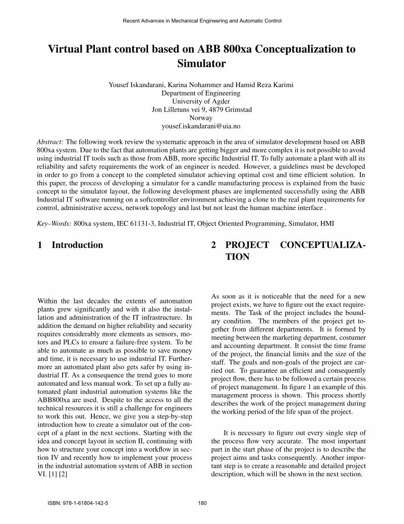
As soon as it is noticeable that the need for a newproject exists, we have to figure out the exact require-ments. The Task of the project includes the bound-ary condition. The members of the project get to-gether from different departments. It is formed bymeeting between the marketing department, costumerand accounting department. It consist the time frameof the project, the financial limits and the size of thestaff. The goals and non-goals of the project are car-ried out. To guarantee an efficient and consequentlyproject flow, there has to be followed a certain processof project management. In figure 1 an example of thismanagement process is shown. This process shortlydescribes the work of the project management duringthe working period of the life span of the project.
It is necessary to figure out every single step ofthe process flow very accurate. The most importantpart in the start phase of the project is to describe theproject aims and tasks consequently. Another impor-tant step is to create a reasonable and detailed projectdescription, which will be shown in the next section.
Recent Advances in Mechanical Engineering and Automatic Control
ISBN: 978-1-61804-142-5 180
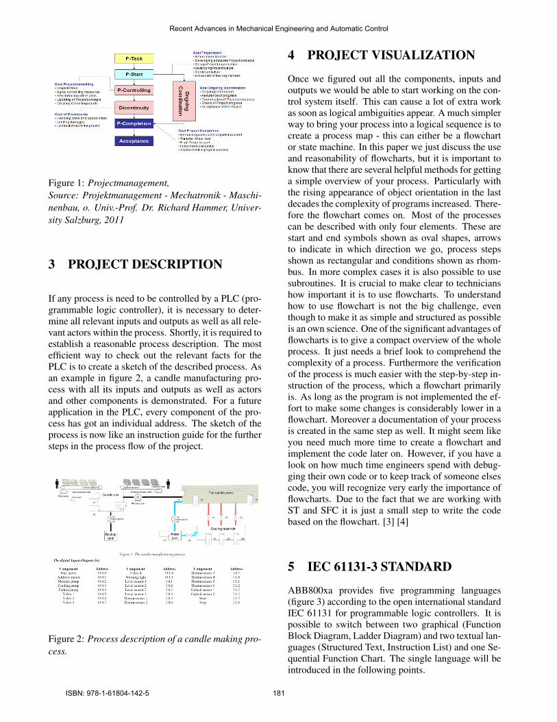
Figure 1: Projectmanagement,Source: Projektmanagement - Mechatronik - Maschi-nenbau, o. Univ.-Prof. Dr. Richard Hammer, Univer-sity Salzburg, 2011
3 PROJECT DESCRIPTION
If any process is need to be controlled by a PLC (pro-grammable logic controller), it is necessary to deter-mine all relevant inputs and outputs as well as all rele-vant actors within the process. Shortly, it is required toestablish a reasonable process description. The mostefficient way to check out the relevant facts for thePLC is to create a sketch of the described process. Asan example in figure 2, a candle manufacturing pro-cess with all its inputs and outputs as well as actorsand other components is demonstrated. For a futureapplication in the PLC, every component of the pro-cess has got an individual address. The sketch of theprocess is now like an instruction guide for the furthersteps in the process flow of the project.
Figure 2: Process description of a candle making pro-cess.
4 PROJECT VISUALIZATION
Once we figured out all the components, inputs andoutputs we would be able to start working on the con-trol system itself. This can cause a lot of extra workas soon as logical ambiguities appear. A much simplerway to bring your process into a logical sequence is tocreate a process map - this can either be a flowchartor state machine. In this paper we just discuss the useand reasonability of flowcharts, but it is important toknow that there are several helpful methods for gettinga simple overview of your process. Particularly withthe rising appearance of object orientation in the lastdecades the complexity of programs increased. There-fore the flowchart comes on. Most of the processescan be described with only four elements. These arestart and end symbols shown as oval shapes, arrowsto indicate in which direction we go, process stepsshown as rectangular and conditions shown as rhom-bus. In more complex cases it is also possible to usesubroutines. It is crucial to make clear to technicianshow important it is to use flowcharts. To understandhow to use flowchart is not the big challenge, eventhough to make it as simple and structured as possibleis an own science. One of the significant advantages offlowcharts is to give a compact overview of the wholeprocess. It just needs a brief look to comprehend thecomplexity of a process. Furthermore the verificationof the process is much easier with the step-by-step in-struction of the process, which a flowchart primarilyis. As long as the program is not implemented the ef-fort to make some changes is considerably lower in aflowchart. Moreover a documentation of your processis created in the same step as well. It might seem likeyou need much more time to create a flowchart andimplement the code later on. However, if you have alook on how much time engineers spend with debug-ging their own code or to keep track of someone elsescode, you will recognize very early the importance offlowcharts. Due to the fact that we are working withST and SFC it is just a small step to write the codebased on the flowchart. [3] [4]
5 IEC 61131-3 STANDARD
ABB800xa provides five programming languages(figure 3) according to the open international standardIEC 61131 for programmable logic controllers. It ispossible to switch between two graphical (FunctionBlock Diagram, Ladder Diagram) and two textual lan-guages (Structured Text, Instruction List) and one Se-quential Function Chart. The single language will beintroduced in the following points.
Recent Advances in Mechanical Engineering and Automatic Control
ISBN: 978-1-61804-142-5 181
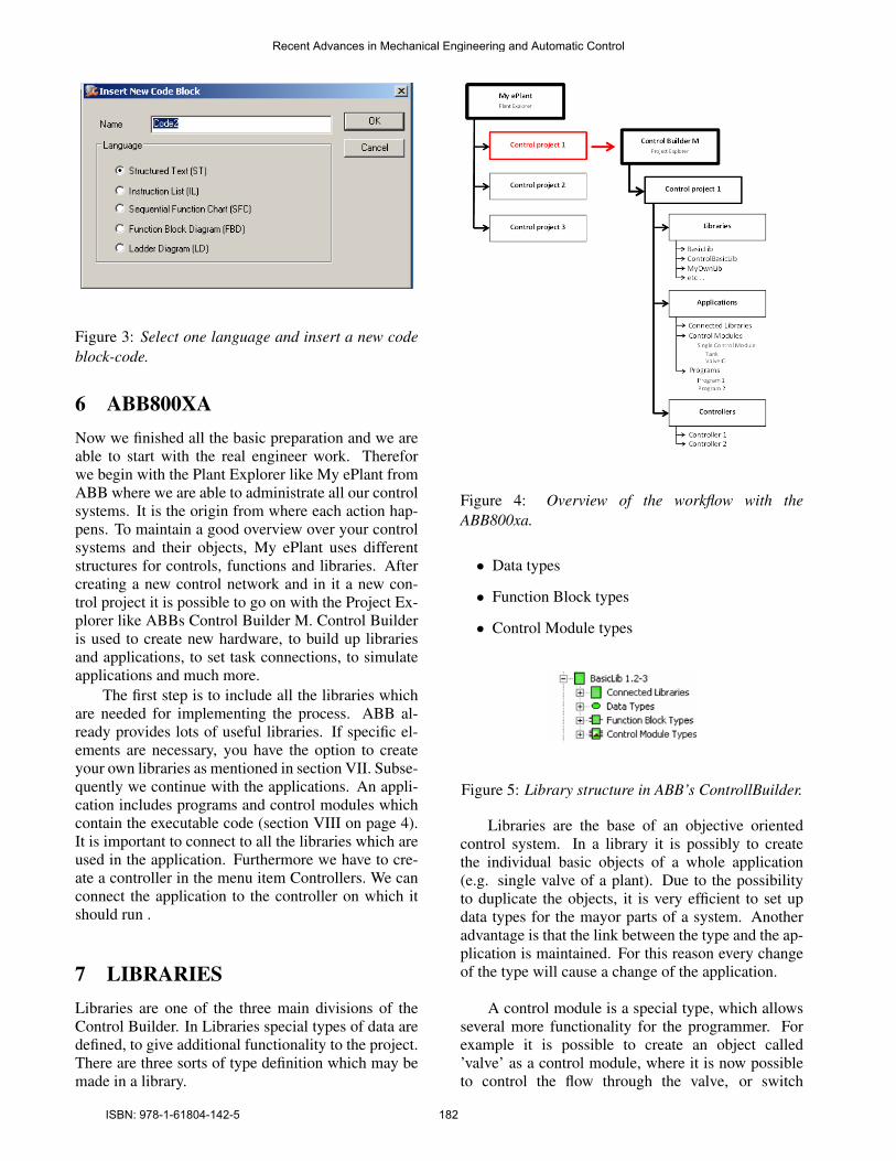
Figure 3: Select one language and insert a new codeblock-code.
6 ABB800XANow we finished all the basic preparation and we areable to start with the real engineer work. Thereforwe begin with the Plant Explorer like My ePlant fromABB where we are able to administrate all our controlsystems. It is the origin from where each action hap-pens. To maintain a good overview over your controlsystems and their objects, My ePlant uses differentstructures for controls, functions and libraries. Aftercreating a new control network and in it a new con-trol project it is possible to go on with the Project Ex-plorer like ABBs Control Builder M. Control Builderis used to create new hardware, to build up librariesand applications, to set task connections, to simulateapplications and much more.
The first step is to include all the libraries whichare needed for implementing the process. ABB al-ready provides lots of useful libraries. If specific el-ements are necessary, you have the option to createyour own libraries as mentioned in section VII. Subse-quently we continue with the applications. An appli-cation includes programs and control modules whichcontain the executable code (section VIII on page 4).It is important to connect to all the libraries which areused in the application. Furthermore we have to cre-ate a controller in the menu item Controllers. We canconnect the application to the controller on which itshould run .
7 LIBRARIESLibraries are one of the three main divisions of theControl Builder. In Libraries special types of data aredefined, to give additional functionality to the project.There are three sorts of type definition which may bemade in a library.
Figure 4: Overview of the workflow with theABB800xa.
• Data types
• Function Block types
• Control Module types
Figure 5: Library structure in ABB’s ControllBuilder.
Libraries are the base of an objective orientedcontrol system. In a library it is possibly to createthe individual basic objects of a whole application(e.g. single valve of a plant). Due to the possibilityto duplicate the objects, it is very efficient to set updata types for the mayor parts of a system. Anotheradvantage is that the link between the type and the ap-plication is maintained. For this reason every changeof the type will cause a change of the application.
A control module is a special type, which allowsseveral more functionality for the programmer. Forexample it is possible to create an object called’valve’ as a control module, where it is now possibleto control the flow through the valve, or switch
Recent Advances in Mechanical Engineering and Automatic Control
ISBN: 978-1-61804-142-5 182
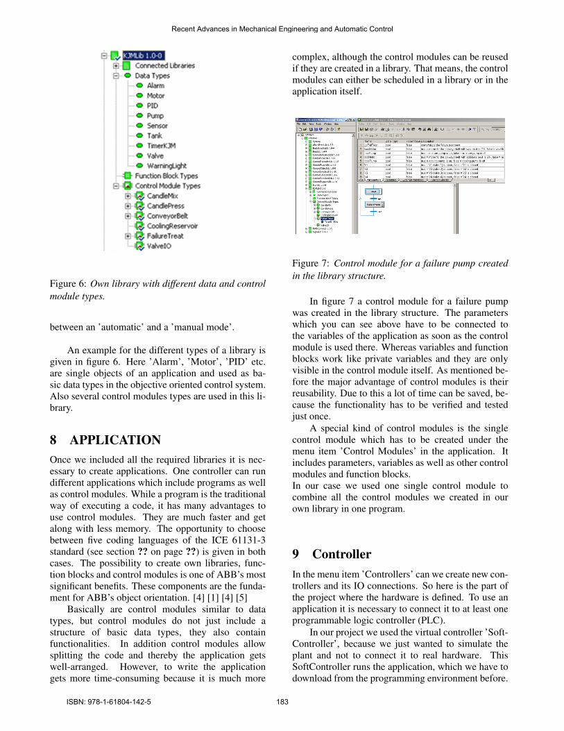
Figure 6: Own library with different data and controlmodule types.
between an ’automatic’ and a ’manual mode’.
An example for the different types of a library isgiven in figure 6. Here ’Alarm’, ’Motor’, ’PID’ etc.are single objects of an application and used as ba-sic data types in the objective oriented control system.Also several control modules types are used in this li-brary.
8 APPLICATIONOnce we included all the required libraries it is nec-essary to create applications. One controller can rundifferent applications which include programs as wellas control modules. While a program is the traditionalway of executing a code, it has many advantages touse control modules. They are much faster and getalong with less memory. The opportunity to choosebetween five coding languages of the ICE 61131-3standard (see section ?? on page ??) is given in bothcases. The possibility to create own libraries, func-tion blocks and control modules is one of ABB’s mostsignificant benefits. These components are the funda-ment for ABB’s object orientation. [4] [1] [4] [5]
Basically are control modules similar to datatypes, but control modules do not just include astructure of basic data types, they also containfunctionalities. In addition control modules allowsplitting the code and thereby the application getswell-arranged. However, to write the applicationgets more time-consuming because it is much more
complex, although the control modules can be reusedif they are created in a library. That means, the controlmodules can either be scheduled in a library or in theapplication itself.
Figure 7: Control module for a failure pump createdin the library structure.
In figure 7 a control module for a failure pumpwas created in the library structure. The parameterswhich you can see above have to be connected tothe variables of the application as soon as the controlmodule is used there. Whereas variables and functionblocks work like private variables and they are onlyvisible in the control module itself. As mentioned be-fore the major advantage of control modules is theirreusability. Due to this a lot of time can be saved, be-cause the functionality has to be verified and testedjust once.
A special kind of control modules is the singlecontrol module which has to be created under themenu item ’Control Modules’ in the application. Itincludes parameters, variables as well as other controlmodules and function blocks.In our case we used one single control module tocombine all the control modules we created in ourown library in one program.
9 ControllerIn the menu item ’Controllers’ can we create new con-trollers and its IO connections. So here is the part ofthe project where the hardware is defined. To use anapplication it is necessary to connect it to at least oneprogrammable logic controller (PLC).
In our project we used the virtual controller ’Soft-Controller’, because we just wanted to simulate theplant and not to connect it to real hardware. ThisSoftController runs the application, which we have todownload from the programming environment before.
Recent Advances in Mechanical Engineering and Automatic Control
ISBN: 978-1-61804-142-5 183
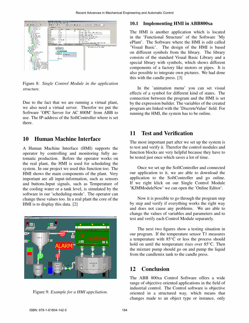
Figure 8: Single Control Module in the applicationstructure.
Due to the fact that we are running a virtual plant,we also need a virtual server. Therefor we put theSoftware ’OPC Server for AC 800M’ from ABB touse. The IP-address of the SoftController where is setthere.
10 Human Machine InterfaceA Human Machine Interface (HMI) supports theoperator by controlling and monitoring fully au-tomatic production. Before the operator works onthe real plant, the HMI is used for scheduling thesystem. In our project we used this function too. TheHMI shows the main components of the plant. Veryimportant are all input-information, such as sensorsand buttons.Input signals, such as Temperature ofthe cooling water or a tank level, is simulated by thesoftware in our ’scheduling-mode’. The operator canchange these values too. In a real plant the core of theHMI is to display this data. [2]
Figure 9: Example for a HMI appcliation.
10.1 Implementing HMI in ABB800xa
The HMI is another application which is locatedin the ’Functional Structure’ of the Software ’MyePlant’. The Software where the HMI is edit called’Visual Basic’. The design of the HMI is basedon different symbols from the library. The libraryconsists of the standard Visual Basic Library and aspecial library with symbols, which shows differentcomponents of a factory like motors or pipes. It isalso possible to integrate own pictures. We had donethis with the candle press. [3]
In the ’animation menu’ you can set visualeffects of a symbol for different kind of states. Theconnection between the program and the HMI is setby the expression builder. The variables of the createdprogram are linked with the ’DiscreteValue’ field. Forrunning the HMI, the system has to be online.
11 Test and VerificationThe most important part after we set up the system isto test and verify it. Therefor the control modules andfunction blocks are very helpful because they have tobe tested just once which saves a lot of time.
Once we set up the SoftController and connectedour application to it, we are able to download theapplication to the SoftController and go online.If we right klick on our Single Control Module’KJMModuleNew’ we can open the ’Online Editor’.
Now it is possible to go through the program stepby step and verify if everything works the right wayand does not cause any problems. We are able tochange the values of variables and parameters and totest and verify each Control Module separately.
The next two figures show a testing situation inour program. If the temperature sensor T1 measuresa temperature with 85◦C or less the process shouldhold on until the temperature rises over 85◦C. Thenthe mixture pump should go on and pump the liquidfrom the candlemix tank to the candle press.
12 ConclusionThe ABB 800xa Control Software offers a widerange of objective oriented applications in the field ofindustrial control. The Control software is objectiveoriented in a structured way, which means thatchanges made to an object type or instance, only
Recent Advances in Mechanical Engineering and Automatic Control
ISBN: 978-1-61804-142-5 184
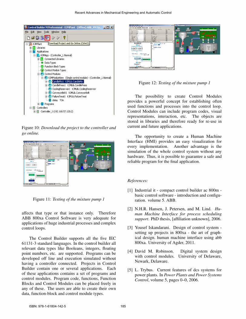
Figure 10: Download the project to the controller andgo online.
Figure 11: Testing of the mixture pump 1
affects that type or that instance only. ThereforeABB 800xa Control Software is very adequate forapplications of huge industrial processes and complexcontrol loops.
The Control Builder supports all the five IEC61131-3 standard languages. In the control builder allrelevant data types like Booleans, integers, floatingpoint numbers, etc. are supported. Programs can bedeveloped off line and execution simulated withouthaving a controller connected. Projects in ControlBuilder contain one or several applications. Eachof these applications contains a set of programs andcontrol modules. Program code, functions, FunctionBlocks and Control Modules can be placed freely inany of these. The users are able to create their owndata, function-block and control module types.
Figure 12: Testing of the mixture pump 1
The possibility to create Control Modulesprovides a powerful concept for establishing oftenused functions and processes into the control loop.Control Modules can include program codes, visualrepresentations, interaction, etc. The objects arestored in libraries and therefore ready for re-use incurrent and future applications.
The opportunity to create a Human MachineInterface (HMI) provides an easy visualization forevery implementation. Another advantage is thesimulation of the whole control system without anyhardware. Thus, it is possible to guarantee a safe andreliable program for the final application.
References:
[1] Industrial it - compact control builder ac 800m -basic control software - introduction and configu-ration. volume 5. ABB.
[2] N.H.R. Hansen, J. Petersen, and M. Lind. Hu-man Machine Interface for process schedulingsupport. PhD thesis, [affiliation unknown], 2006.
[3] Yousef Iskandarani. Design of control system -setting up projects in 800xa - the art of graph-ical design. human machine interface using abb800xa. University of Agder, 2011.
[4] David M. Robinson. Digital system designwith control modules. University of Delaware,Newark, Delaware.
[5] L. Trybus. Current features of dcs systems forpower plants. In Power Plants and Power SystemsControl, volume 5, pages 0–0, 2006.
Recent Advances in Mechanical Engineering and Automatic Control
ISBN: 978-1-61804-142-5 185