volvo v70r brake rotor heat transfer
DESCRIPTION
Volvo V70R Brake Rotor Heat Transfer. Tate Fanning, Harrison Douglass. Introduction. - PowerPoint PPT PresentationTRANSCRIPT
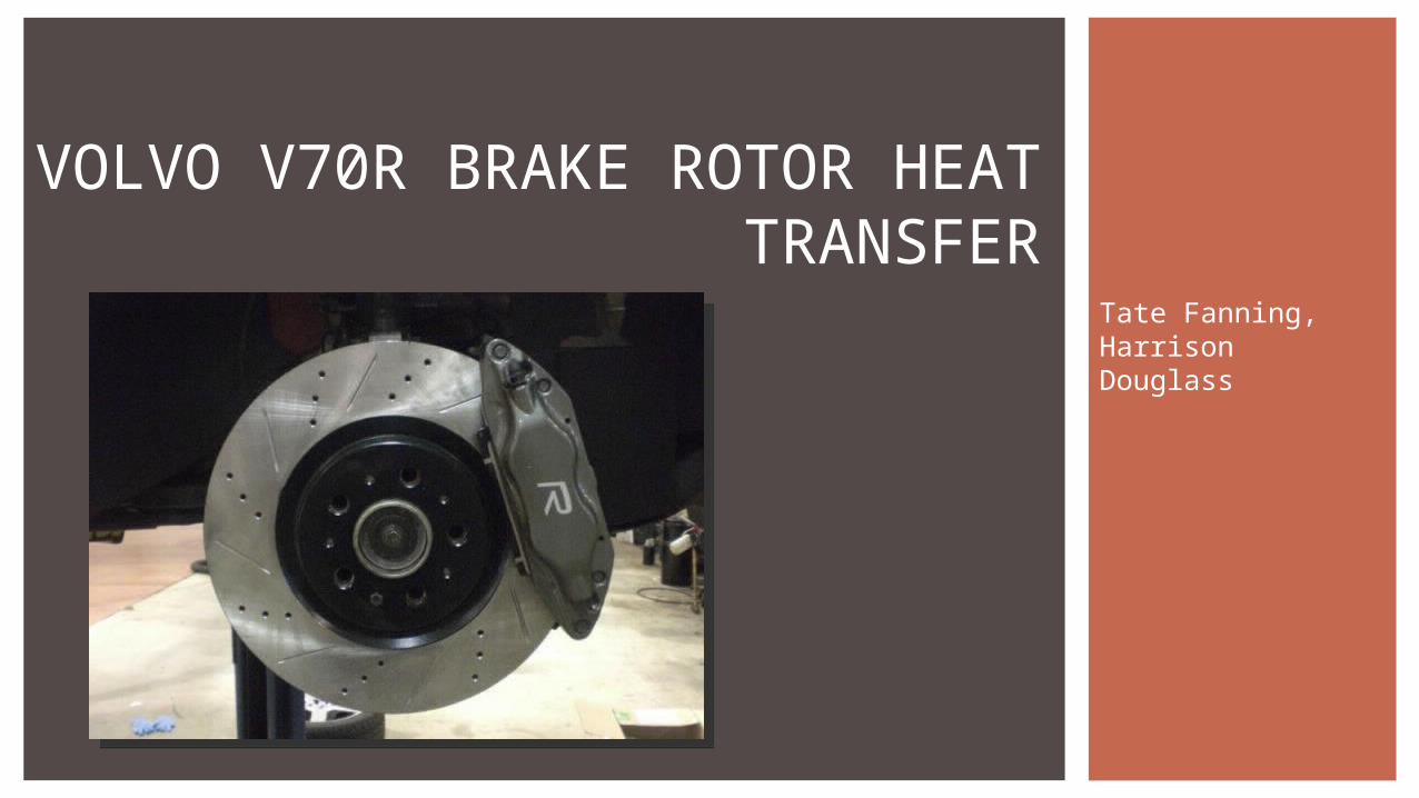
Tate Fanning, Harrison Douglass
VOLVO V70R BRAKE ROTOR HEAT TRANSFER
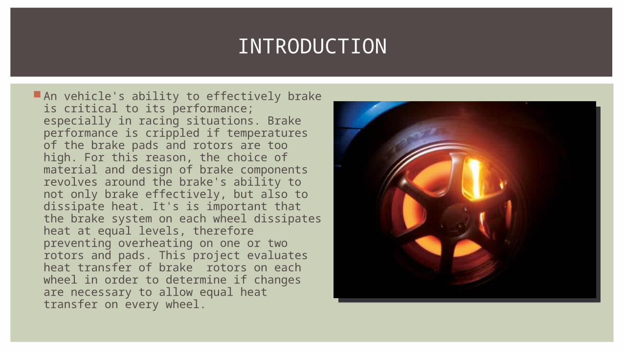
An vehicle's ability to effectively brake is critical to its performance; especially in racing situations. Brake performance is crippled if temperatures of the brake pads and rotors are too high. For this reason, the choice of material and design of brake components revolves around the brake's ability to not only brake effectively, but also to dissipate heat. It's is important that the brake system on each wheel dissipates heat at equal levels, therefore preventing overheating on one or two rotors and pads. This project evaluates heat transfer of brake rotors on each wheel in order to determine if changes are necessary to allow equal heat transfer on every wheel.
INTRODUCTION
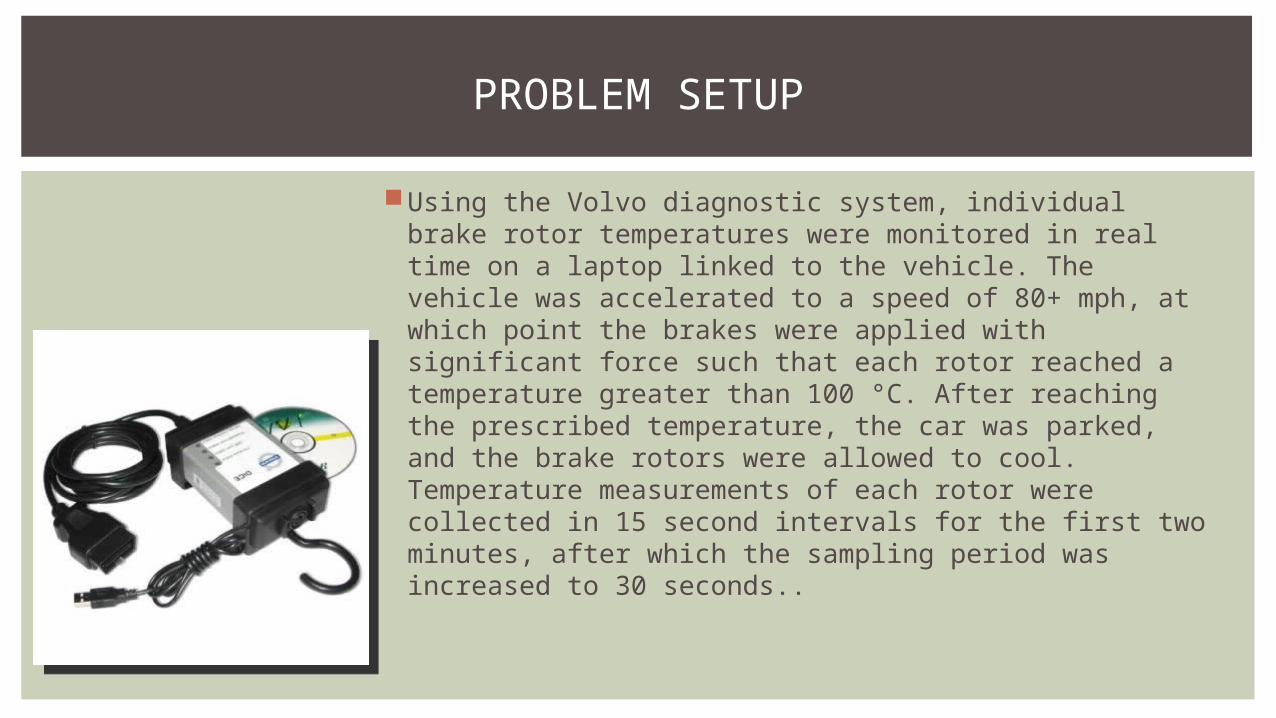
Using the Volvo diagnostic system, individual brake rotor temperatures were monitored in real time on a laptop linked to the vehicle. The vehicle was accelerated to a speed of 80+ mph, at which point the brakes were applied with significant force such that each rotor reached a temperature greater than 100 °C. After reaching the prescribed temperature, the car was parked, and the brake rotors were allowed to cool. Temperature measurements of each rotor were collected in 15 second intervals for the first two minutes, after which the sampling period was increased to 30 seconds..
PROBLEM SETUP
Brake rotors are subjected only to free and forced convection in air at 45 °F (280 K) and flowing at 0.5 m/s.
Brake rotors are made of carbon steel.Each rotor can be modeled as a vertical plate of diameter
330 mm in a cross flow.
ASSUMPTIONS

The initial hot temperature of each brake rotor was first measured; these measurements were held as the surface temperatures for future calculations.
The Reynolds and Prandtl numbers for the cross flow (0.5 m/s at 280-300K) were found.These numbers were considered to choose the proper correlation; based on the results
and desired measure of accuracy, the Hilpert correlation was chosen. While this is less accurate the the Churchill correlation, it provides a good estimate and will allow us to see if the heat transfer rates are equal for each rotor.
The Nusslet number was found for each brake rotor.The Grashof number for the flow was found and compared to the square of the Reynolds
number. It was found that the Reynolds number squared was much larger than the Grashof number, which implies that free convection plays an insignificant role in the problem, so it was neglected.
The convection heat transfer coefficient was found and used to calculate the rate of heat transfer for each brake rotor.
The measured temperatures were then plotted.See Appendix 2 for hand calculations.
SOLUTION AND PROCEDURE

The rate of heat transfer was found to be equal for each front and each rear rotor respectively, but unequal between fronts and rear rotors.
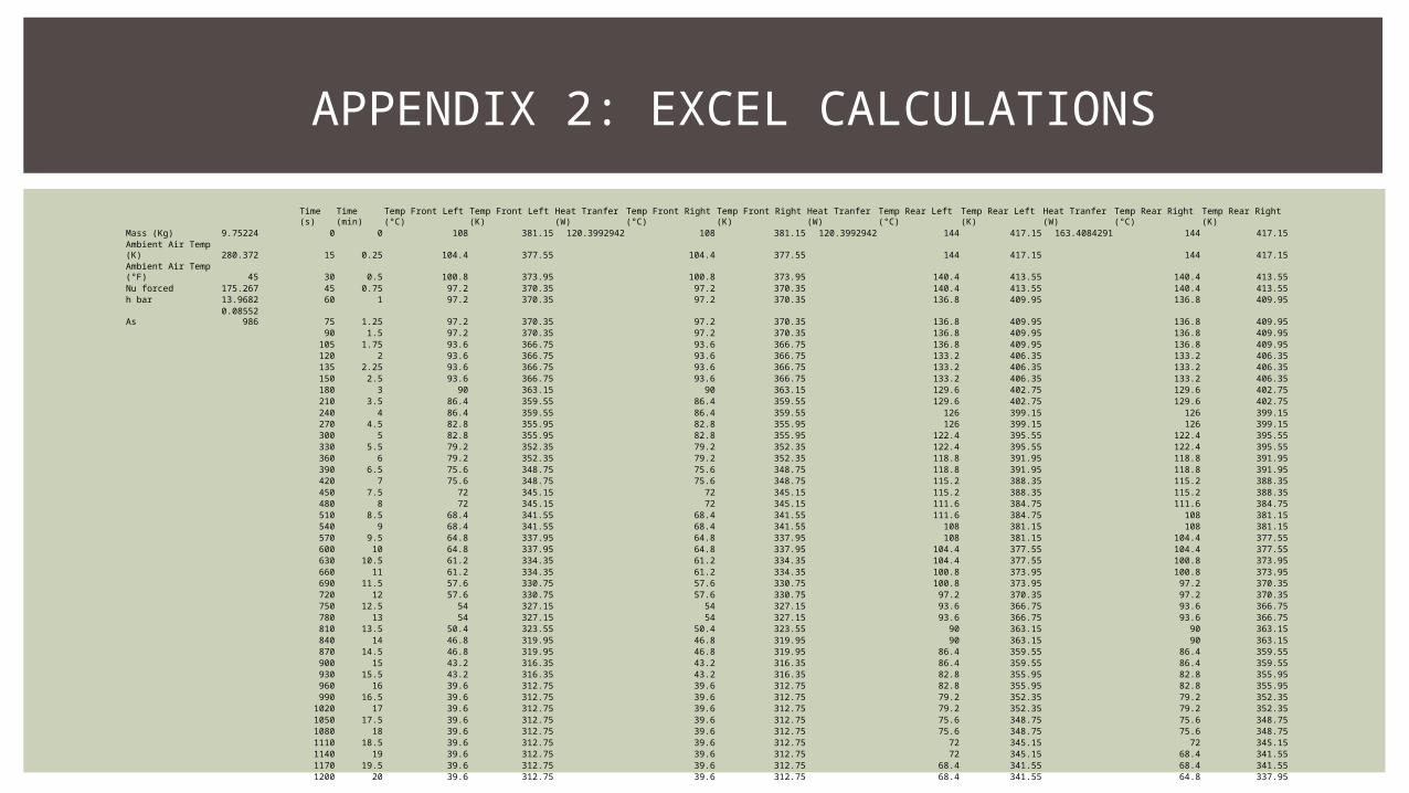
The rate of heat transfer for the front rotors was found to be: 120.3992942 W/m. The rate of heat transfer for the rear rotors was found to be: 163.4084291 W/m. Each brake rotor seemed to cool at the same rate, as seen in the below charts, but the rear rotors
started at a higher temperature, and removed more heat than the front rotors.
RESULTS
The front rotors were more effective in that they remained at a lower temperature, despite providing 70% of the braking force.
The rear rotors were more effective in dissipating heat. This is likely due to the fact that they are thinner than the front rotors, or they may have a different interior vane pattern.
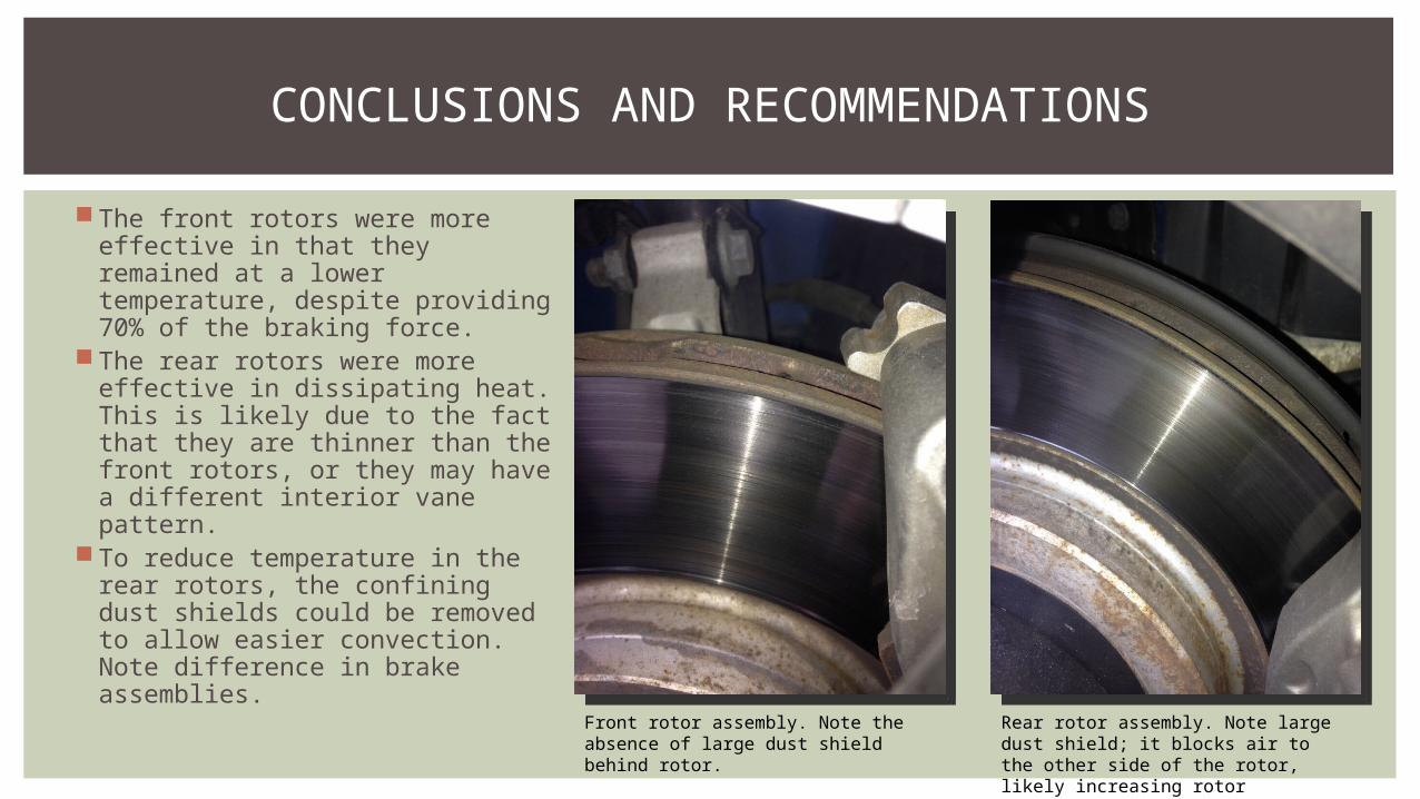
To reduce temperature in the rear rotors, the confining dust shields could be removed to allow easier convection. Note difference in brake assemblies.
CONCLUSIONS AND RECOMMENDATIONS
Front rotor assembly. Note the absence of large dust shield behind rotor.
Rear rotor assembly. Note large dust shield; it blocks air to the other side of the rotor, likely increasing rotor temperature.
CONCLUSIONS AND RECOMMENDATIONS CONT’D
To foster a higher rate of heat transfer and lower rotor temperatures, larger diameter rotors can be used, or the rotor thickness can be decreased. However, care must be taken to avoid exceeding the material properties and causing warping.
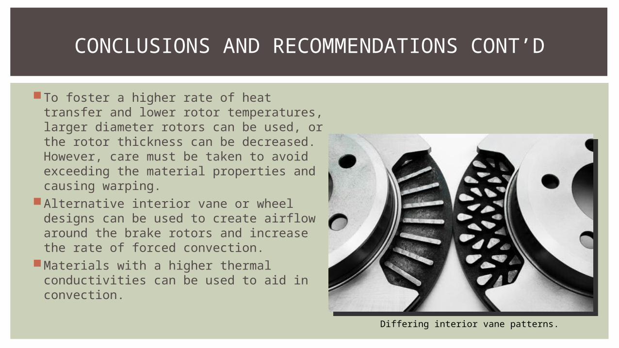
Alternative interior vane or wheel designs can be used to create airflow around the brake rotors and increase the rate of forced convection.
Materials with a higher thermal conductivities can be used to aid in convection.
Differing interior vane patterns.

APPENDIX 1: HAND CALCULATIONS
For better viewing, this image is also hosted at: http://i.imgur.com/KS6Yf7Y.png
APPENDIX 2: EXCEL CALCULATIONS
Time (s) Time (min) Temp Front Left (°C) Temp Front Left (K) Heat Tranfer (W) Temp Front Right (°C) Temp Front Right (K) Heat Tranfer (W) Temp Rear Left (°C) Temp Rear Left (K) Heat Tranfer (W) Temp Rear Right (°C) Temp Rear Right (K)Mass (Kg) 9.75224 0 0 108 381.15 120.3992942 108 381.15 120.3992942 144 417.15 163.4084291 144 417.15Ambient Air Temp (K) 280.372 15 0.25 104.4 377.55 104.4 377.55 144 417.15 144 417.15Ambient Air Temp (°F) 45 30 0.5 100.8 373.95 100.8 373.95 140.4 413.55 140.4 413.55Nu forced 175.267 45 0.75 97.2 370.35 97.2 370.35 140.4 413.55 140.4 413.55h bar 13.9682 60 1 97.2 370.35 97.2 370.35 136.8 409.95 136.8 409.95
As0.0855298
6 75 1.25 97.2 370.35 97.2 370.35 136.8 409.95 136.8 409.9590 1.5 97.2 370.35 97.2 370.35 136.8 409.95 136.8 409.95
105 1.75 93.6 366.75 93.6 366.75 136.8 409.95 136.8 409.95120 2 93.6 366.75 93.6 366.75 133.2 406.35 133.2 406.35135 2.25 93.6 366.75 93.6 366.75 133.2 406.35 133.2 406.35150 2.5 93.6 366.75 93.6 366.75 133.2 406.35 133.2 406.35180 3 90 363.15 90 363.15 129.6 402.75 129.6 402.75210 3.5 86.4 359.55 86.4 359.55 129.6 402.75 129.6 402.75240 4 86.4 359.55 86.4 359.55 126 399.15 126 399.15270 4.5 82.8 355.95 82.8 355.95 126 399.15 126 399.15300 5 82.8 355.95 82.8 355.95 122.4 395.55 122.4 395.55330 5.5 79.2 352.35 79.2 352.35 122.4 395.55 122.4 395.55360 6 79.2 352.35 79.2 352.35 118.8 391.95 118.8 391.95390 6.5 75.6 348.75 75.6 348.75 118.8 391.95 118.8 391.95420 7 75.6 348.75 75.6 348.75 115.2 388.35 115.2 388.35450 7.5 72 345.15 72 345.15 115.2 388.35 115.2 388.35480 8 72 345.15 72 345.15 111.6 384.75 111.6 384.75510 8.5 68.4 341.55 68.4 341.55 111.6 384.75 108 381.15540 9 68.4 341.55 68.4 341.55 108 381.15 108 381.15570 9.5 64.8 337.95 64.8 337.95 108 381.15 104.4 377.55600 10 64.8 337.95 64.8 337.95 104.4 377.55 104.4 377.55630 10.5 61.2 334.35 61.2 334.35 104.4 377.55 100.8 373.95660 11 61.2 334.35 61.2 334.35 100.8 373.95 100.8 373.95690 11.5 57.6 330.75 57.6 330.75 100.8 373.95 97.2 370.35720 12 57.6 330.75 57.6 330.75 97.2 370.35 97.2 370.35750 12.5 54 327.15 54 327.15 93.6 366.75 93.6 366.75780 13 54 327.15 54 327.15 93.6 366.75 93.6 366.75810 13.5 50.4 323.55 50.4 323.55 90 363.15 90 363.15840 14 46.8 319.95 46.8 319.95 90 363.15 90 363.15870 14.5 46.8 319.95 46.8 319.95 86.4 359.55 86.4 359.55900 15 43.2 316.35 43.2 316.35 86.4 359.55 86.4 359.55930 15.5 43.2 316.35 43.2 316.35 82.8 355.95 82.8 355.95960 16 39.6 312.75 39.6 312.75 82.8 355.95 82.8 355.95990 16.5 39.6 312.75 39.6 312.75 79.2 352.35 79.2 352.35
1020 17 39.6 312.75 39.6 312.75 79.2 352.35 79.2 352.351050 17.5 39.6 312.75 39.6 312.75 75.6 348.75 75.6 348.751080 18 39.6 312.75 39.6 312.75 75.6 348.75 75.6 348.751110 18.5 39.6 312.75 39.6 312.75 72 345.15 72 345.151140 19 39.6 312.75 39.6 312.75 72 345.15 68.4 341.551170 19.5 39.6 312.75 39.6 312.75 68.4 341.55 68.4 341.551200 20 39.6 312.75 39.6 312.75 68.4 341.55 64.8 337.95