westinghouse - electrical part manual s · westinghouse • negotiation data when corresponding...
TRANSCRIPT

"""··'
Westinghouse
• Network Price Modifications
Page N umber
General information . . . . . . . . . . . 1 Ordering i nformation . . . . . . . . . . . 1 Insulating l iquid . . . . . . . . . . . . . . 1 Voi d i ng of warranties . . . . . . . . . . 1 Exchange allowance . . . . . . . . . . . 1 Negotiation data . . . . . . . . . . . . . . 1 , 2 Final base price determi nation . . . . 2 Electrical characteristics . . . . . . . . 3 Accessories and location . . . . . . . . 4, 5 Terminal designations-
vector relations ..... ....... . Mechanical characteristics ... .. . Tests ...... .......... ... ... . Current table ................ .
B . { Standard ........ . ase pr�ces Non-standard .... .
P . d'f' . { Electrical .. .
nee mo 1 1cat10ns Mechanical .
General Information
5 3 2 3 6 6
7-1 0 1 1 -20
These pricing instructions cover the various types of transformers used in ac secondary network systems. The range of ratings and types of equipment available are listed as follows:
Type: Liquid (oil or lnerteen) Ventilated dry type N itrogen filled or C4F8 gas filled dry type
Kva: 300-2500 (3 phase) 1 00- 833 (1 phase)
Voltage: 5-34.5 Kv (liquid) 5-1 5.0 Kv (dry type)
Service: Subway Vault
Prices determined from these pricing instructions may be used for estimating purposes and thereby eliminate a large number of the requests to the Power Transformer D ivision for preliminary prices. However, in so doing, a copy of the letter quoting the estimating prices must be sent to the Power Transformer Division at Sharon to serve as an i n dicator of possible future business. All fi nal prices must be obtained from the Power Transformer D ivision at Sharon.
Prices effective July 1, 1968; subject to change without notice. For standard terms and conditions of sales, refer to Selling Policy 47-000.
Ordering Information When entering an order on the PowerTransformer Division for any of the network ratings listed herein, care should be taken to include complete i nformation i n the order write-up. Shipments quoted on negotiations are based on min imum time required to manufacture the u nits after receipt of complete information. To facilitate design, d rafting, shop i n formation, and actual manufacturing, the following informati o n must appear i n the order write-up; such as-
Number of Units
Kva
Phase
Frequency
Hv Ratings 1 . Rated voltage and taps 2. Delta or wye connected rated voltage
lv Rating 1 . Rated voltage
Type 1 . Liquid (oil or lnerteen) 65°C rise 2. Ventilated dry sooc rise 3. Gas filled dry 1 50°C rise
Service 1 . Subway-periodic submersion 2. Vault-occasional submersion
Hv Switch 1 . 3-position d isconnecting and ground
ing 2. 2-position d isconnecting 3. 2-position grounding
Hv Entry 1 . List complete cable information
(a) Single or three conductor (and size)
(b) Type of insulation (c) Protective covering (d) O.D. of insulation or protective
coveri n g 2. Top or bottom entrance
Wiping Sleeve 1 . Copper spun brazed on or removable 2. Where single sleeve is used
(a) Straight or 45 degree (b) Vent plug in sleeve required
Vector Relation 1 . Standard 2. N on-standard (furnish sketch)
Pl 47-120 Page 1
Network Transformers For Ac Secondary Network Systems
Liquid-Immersed, Ventilated or Gas Filled Dry-Type 300-2500 Kva
Spare Gaskets Spare gaskets, one for the Lv throat and one for the cover handhole are normally supplied with each unit. Spare gaskets will also be supplied at no additional charge, one per shop order for the Hv terminal chamber and one per shop order for Hv switch compartment if specially requested as a separate item on the transformer order write-up.
Insulating Liquid The i nsulating liquid (oil or lnerteen) i s normally shipped i n the tank with the transformer. No omission allowance will be made where customer's requ i rements call for omission of the oil or l nerteen.
Warranties Standard Warranty- See S P 47-000 S pecial Warranty See Rule 39 and Rule 40
Voiding of Warranties It should be noted that if network transformers of Westinghouse manufacture are operated with other than Wemco "C" oil or Westi nghouse approved oil, our standard warranty is void in cases of trouble traceable to oil. Also if non-flammable network transformers of Westinghouse manufacture are operated with other than "lnerteen" our standard warranty i s void in case of trouble traceable to non-flammable l iquid.
Accelerated or Delayed Payments See Rule 4 1 .
Exchange Allowance An exchange allowance for old transformers i n connection with the purchase of new network transformers is not permitted.
Delivery See Rule 42.
July 1,1968 Supersedes Price list 47-120, page3 1-20. dated March 29, 1967 E, C/2081/PL www .
Elec
tricalP
artM
anua
ls . c
om
PL 47-120 Page 2
Westinghouse
• Negotiation Data When corresponding with Sharon on negotiations, it is necessary to give complete identifying data.
Units required to match other Westinghouse units in an existing system, need only be identified by shop order or serial number. For all other units delays in quotations can be avoided by listing the following information:
Number of units
Kva
Cooling (Oil, lnerteen, ventilated dry, gas filled dry)
Type (Vault or subway)
Temperature Rise (65°C, 55°C, 80°C or 150°C)
Phase (1 or 3 phase)
Frequency (60 cycles or other)
Hv rating ( Rated voltage and taps)
( Delta or wye)
Lv rating ( Nominal voltage) ( Delta or wye)
Vector Relation (Standard or non·standard)
Impedance
Wye operation (State how neutral is to be brought out)
Accessories (If any other than standard are required,
list the accessories and any special loca· tions)
Dimensions Refer to Sharon Plant
Delivery (Advise required shipment)
Final Price Determination A. Definition of Standard: A standard network transformer is one which meets the electrical and mechanical description of the USA Standard C57 .12.40.
The definition of standard has been expanded to include ventilated dry·type and gas filled dry-type transformers. Both Section A and Section B. USA Standards are covered in the pricing rules. Only Section A standards are covered in the descriptive summary. For Section B standards, refer to USA standards for secondary network transformers.
B. Standard or Special: Determine whether or not the network transformer can be priced as a standard unit. The following procedure is suggested :
1. Check standard base price lists, pages 8 and 9 for allowable
a. Hv rating and taps b. Lv rating c. Kva rating d. Impedance e. Sound level
2. Check drawing on page 5 for allowable accessories and their location.
3. Check drawings on page 5 for allowable vector relations.
4. Check Type and Electrical Modifications, pages 7 to 10.
5. Check Mechanical Modifications, pages 11 to 20.
Reference can also be made to USA Standard C57.12. 40 for secondary network transformers.
C. High Voltage Termination: To either the standard or non-standard base price make an addition for the applicable termination of the primary cable. Rules 25 to 28 inclusive will apply.
D. Percentage Additions: Percentage additions applicable from electrical and/or mechanical modifications are to be made to the selected base price. Total the individual percentage adders and make one multiplication to the selected base price. The resulting dollar addition (dropping all cents) must be added to the base price.
E. Dollar Additions: Dollar additions applicable from electrical and/or mechanical modifications are to be made to the selected base price.
F. Deductions: No deductions are allowed from any prices for the omission of standard accessories.
G. Packing for Overseas Shipment: Where packing for overseas or export shipment is involved, add 5% to the price and drop all cents. Export packing does not include weather proofing or special preservative treatment.
Standard Tests
The following tests will be made on all transformers except as specifically stated below. The numbers shown do not necessarily indicate the sequence in which the tests will be made. All tests will be made in accordance with the latest revision of United States Standard Test Code C57.12.90.
1. Resistance measurements of all windings on the rated voltage connection of each unit and at the tap extremes of one unit only of a given rating on an order.
2. Ratio tests on the rated voltage connection and on all tap connections.
3. Polarity and phase-relation tests on the rated voltage connection.
4. No load loss at rated voltage on the rated connection.
5. Exciting current at rated voltage on the rated voltage connection.
6. Impedance and load loss at rated current on the rated voltage connection of each unit and on the tap extremes of one unit only of a given rating on an order.
7. Temperature test:
A. Temperature test or tests will be made on one unit only of an order covering one or more units of a given rating. Tests will be made only when there is not available a record of a temperature test, made in accordance with USA Standards, on duplicate or essentially duplicate unit.
Tests, when made, will be made under conditions specified in American Standards for transformers.
B. Subject to the limitations of the preceding paragraph (A), when a transformer is supplied with auxiliary cooling equipment to provide one additional Kva rating, temperature tests will be made on both nameplate Kva ratings.
8. Applied potential tests.
9. Induced potential tests.
Field Testing
For de tests at the factory, use the ac factory test value times 1. 41.
For ac or de acceptance tests in the field, use the factory test value times .75.
For field ac or de periodic tests for one minute, use the factory test value times .65. All de and ac test values given above are based on a time duration of one minute. For five minute tests, multiply one minute tests by 90 per cent.
With the disconnecting switches, either two position or three position, in the open position the cable can be tested periodically in the field with de for five minutes as follows:
Switch Rating Liquid Air
15 Kv Switches 1 45000 Volts 43700 Volts 25 Kv Switches 65000 Volts ... .. ... . 33 Kv Switches 82500 Volts . . . . . . . . •
www . El
ectric
alPar
tMan
uals
. com
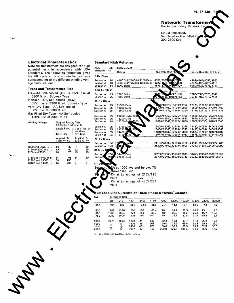
Electrical Characteristics Network transformers are designed for high potential tests in accordance with USA Standards. The following tabulation gives the 60 cycle ac one minute factory tests corresponding to the different winding voltage classifications:
Types and Temperature Rise
Oii-OA Self-cooled (OISC). 65oC rise at 3300 ft. alt. Subway Type
lnerteen-OA Self-cooled (I ISC) 65•c rise at 3300 ft. alt. Subway Type
Vent. Dry Type-AA Self-cooled SO"C rise at 3300 ft. alt.
Gas Filled Dry Type-AA Self-cooled 150"C rise at 3300 ft. alt.
Winding Voltage
1200 and Less ... ... 41 60 to 5000 Incl.. . . 7200 and 7500 . • . . . .
11500 to 14400 Incl.. 22900 and 24000 . . . • 26400 and 34400 . ...
I Original Factory Test 60 Cycles 1 Minute Ac
. LiquidRifed�-1 GaSFilled or
. or Ventilated i_Gas Filled_: Dry Tyll"_ I Applied BIL i Applied BIL
Test: Kv Kv ! Test: Kv Kv
10 30 4 10 19 60 12 25 26 75 19 35
34 95 31 50 50 150 70 200
Standard High Voltages
PL 47-120 Page 3
Network Transformers For Ac Secondary Network Systems
Liquid-Immersed, Ventilated or Gas Filled Dry-Type 300-2500 Kva
ASA BIL I High Voltall."_�----Standard Kv Rating Taps with 216Y/125 L. V. Taps with 480Y/277 L. V. 5 Kv Class Section A SO 1. 4160 GrdY /2400 & 4160 Delta 4056/3952/3848/3744 4368/4264/4056/3952 Section A 60 4330 GrdY/2500 &4330 Delta 4222/4114/4006/3898 4547/4438/4228/4113 Section_�-�()_ 5000 _[)_elta .... .. 487_314750/�625/4500 __ 5250/512!)£�?5/4750_
15 Kv Class Section A 95 Section A 95 Section A 95
Section A 95 Section A 95 Section A 95
7200 Delta 7500 Delta
11500 Delta 12000 Delta 12500 Delta
13000 GrdY/7500 13200 Delta 13200 GrdY /7620
11213/10926/10639/10352 12075/11787/11213/10925 11700/11400/11100/10800 12600/12300/11700/11400 12190/11875/11565/11250 13125/12812/12188/11875
12675/12350/12025/11700 13650/13325/12675/12350 12870/12540/12210/11880 13860/13530/12870/12540 12870/12540/12210/11880 13860/13530/12870/12540
Section A 95 13750 Delta 13406/13063/12719/12375 14437/14094/13406/13063 Section A 95 13750 GrdY/7940 13406/13063/12719/12375 14437/14094/13406/13063 Section A 95 14400 Delta 14040/13680/13320/12960 15120/14760/14040/13680 Sec!i()l1__�_9_!5__13750 Delta _ ___
.. __ 1_3578/134()6/13234/1_3063 13578/13406/132_34/1 3063
34.5 Kv Class Section A 200 34400 Delta Section B 200 27060 Delta
36200/35300/33500/32600 36200/35300/33500/32600 26730/26400/26070/25740 26730/26400/26070/25740
Impedance
Section A: 5% at 1 000 kva and below. 7 % above 1 000 kva
Section B: 4% at Lv ratings of 216Y /125 volts ,..,,.. . c • 7% at Lv ratings of • 480Y /277 volts
Full Load Line Currents of Three-Phase Network: Circuits
Kva
300
500 600 750
1000 1500 2000 2500
--�--- �-��···· I Circuit Voltage 208 216 480 833 802 361
1388 1336 601 1665 1604 722 2082 2005 902
2776 2673 1203 <D <D 1804 <D <D 2406 <D <D 3007
2400 72.2
120 144 180
241 361 481 601
Q) Protectors not available in this rating.
4160 7200 12000 13200 41.6 24.1 14.4 13.1
69.4 40.1 24.1 21.9 83.3 48.1 28.9 26.2
104 60.1 36.1 32.8
139 80.2 48.1 43.7 208 120.0 72.2 65.6 278 160.0 96.2 87.5 347 200.0 120.3 109.3
13800 22000 33000 12.6 7.9 5.2
20.9 13.1 8.7 25.1 15.7 10.5 31.4 19.7 13.1
41.8 26.2 17.5 62.8 39.3 26.2 83.7 52.5 35.0
104.6 65 5 43.7
www . El
ectric
alPar
tMan
uals
. com
PL 47-120 Page 4
Westinghouse
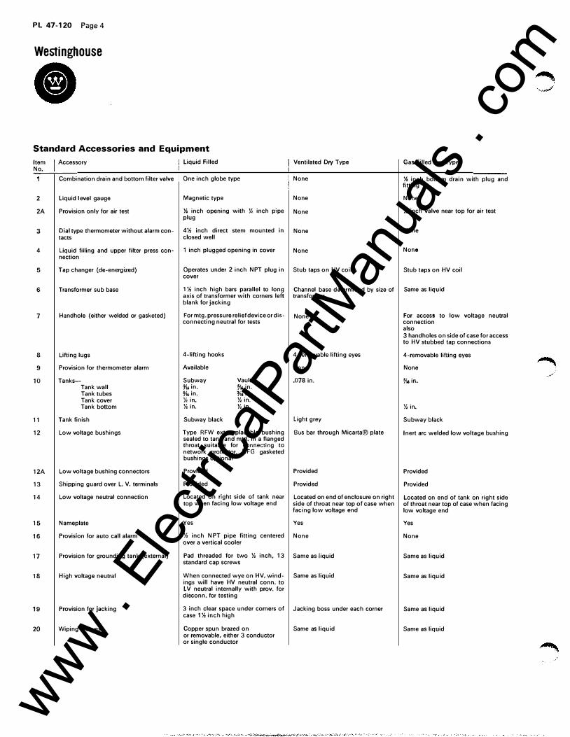
• Standard Accessories and Equipment
Item No.
2
2A
3
4
5
6
7
8
9
10
11
12
12A
13
14
15
16
17
18
19
20
Accessory
Combination drain and bottom filter valve
liquid level gauge
Provision only for air test
Dial type thermometer without alarm con-tacts
liquid filling and upper filter press con-nection
Tap changer (de-energized)
Transformer sub base
Handhole (either welded or gasketed)
lifting lugs
Provision for thermometer alarm
Tanks-Tank wall Tank tubes Tank cover Tank bottom
Tank finish
Low voltage bushings
Low voltage bushing connectors
Shipping guard over L. V. terminals
Low voltage neutral connection
Nameplate
Provision for auto call alarm
Provision for grounding tank (external)
High voltage neutral
Provision for jacking
Wiping sleeves
liquid Filled
One inch globe type
Magnetic type
% inch opening with )!, inch pipe plug
4% inch direct stem mounted in closed well
1 inch plugged opening in cover
Operates under 2 inch NPT plug in cover
1% inch high bars parallel to long axis of transformer with corners left blank for jacking
For mtg. pressure relief device or dis-connecting neutral for tests
4-lifting hooks
Available
Subway 71• in. 716 in. *in. %in.
Vault 716 in. o/" in. %in. %in.
Ventilated Dry Type Gas Filled Dry Type
! None % inch bottom drain with plug and fitting
None None
None Y.. inch valve near top for air test
None None
None None
Stub taps on HV coil Stub taps on HV coil
Channel base determined by size of Same as liquid transformer
None For access to low voltage neutral connection
4-removable lifting eyes
None
.078 in.
also 3 handholes on side of case for access to HV stubbed tap connections
4-removable lifting eyes
None
716 in.
%in.
Subway black light grey Subway black
Type RFW ext. replacable bushing Bus bar through Micarta® plate sealed to tank and mtd. in a flanged throat suitable for connecting to network protector. RFG gasketed bushings optional
Provided
Provided
Located on right side of tank near top when facing low voltage end
Yes
% inch NPT pipe fitting centered over a vertical cooler
Pad threaded for two % inch, 13 standard cap screws
When connected wye on HV, windings will have HV neutral conn. to l V neutral internally with prov. for disconn. for testing
3 inch clear space under corners of case 1% inch high
Copper spun brazed on or removable, either 3 conductor or single conductor
Provided
Provided
Located on end of enclosure on right side of throat near top of case when facing low voltage end
Yes
None
Same as liquid
Same as liquid
Jacking boss under each corner
Same as liquid
Inert arc welded low voltage bushing
Provided
Provided
Located on end of tank on right side of throat near top of case when facing low voltage end
Yes
None
Same as liquid
Same as liquid
Same as liquid
Same as liquid
www . El
ectric
alPar
tMan
uals
. com
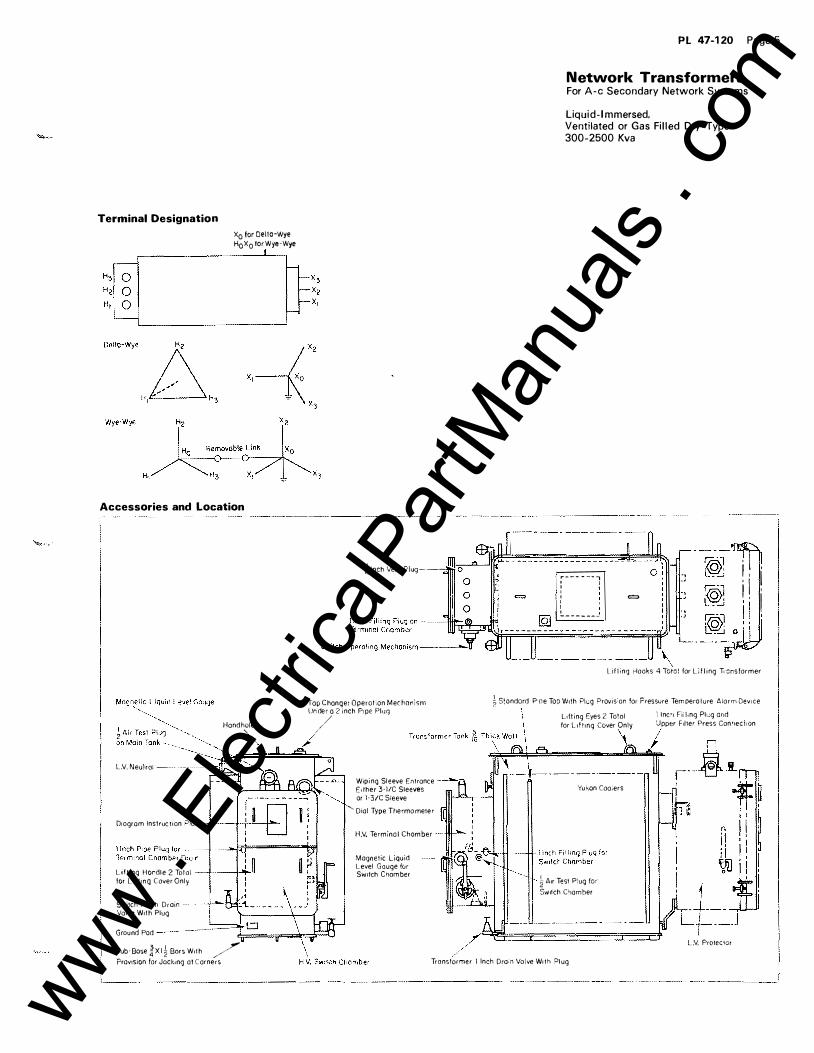
Terminal Designation
x0 for Delto-Wye H0x0 torWye-Wye
I
Accessories and Location
L ,V. Neu Jroi ��-
D1ogram Instruction .i:>!ole
Hand hole '
Uflmg H ocdle 2 Toto I -+--�+->,... for Llftmq Cover Only
Switch I Inch Dra1n ·�··-�+"--!-\,<!'. Valve W1lh Plug
4 1nch Vent Plug----
Tap Changer Operot:on Methorism Un der a 2 inch P1pe Pluq
/ /
/
Wipi ng Sleeve Entrance Eilher 3·1/C Sleeves or 1·3/C Sleeve
'·Dial Type The .. mometer
H.V. Terminal Chamber
Magnetic Liquid -·�--.'!'!itic[C)J Level Gauge fur S;,.nfch Chamber
PL 47-120 Page 5
Network Transformers For A-c Secondary Network Systems
Liquid- Immersed. Ventilated or Gas Filled Dry-Type 300-2500 Kva
,---- - -- ., ' I
: ' I ' I
�-------�
=
\
., _,
., J
i I . . j I I. ,. i I
Lifting Hooks 4 Toto! for Llfling Ti-ansformer
� S•ondard P -oe Top W1th Pl�.:g Provis:on for Pressure Temperature Alorrn Dev1ce
L1fti ng Eyes 2 Total -. lnc'l Fii!.ng Plt.:.g and
for Llftmg Cover Only Upper F1l1er Press ConrJeCliOn
' I Yukon Coo;ers
� A1r Test P:ug for
Sw1tch C'lamber
Ground Pod ----------:�;�==rr=dFiJ;!::::t\ /r���======���
Sub·Bose �XI � Bars Woih /_r Prav1sion for Jack1ng ot Corners Tronsf�mer 1 Inch Drain Vo!ve W1th ?lug
LV. ProleClOt
www . El
ectric
alPar
tMan
uals
. com
PL 47-120 Page 6
Westinghouse
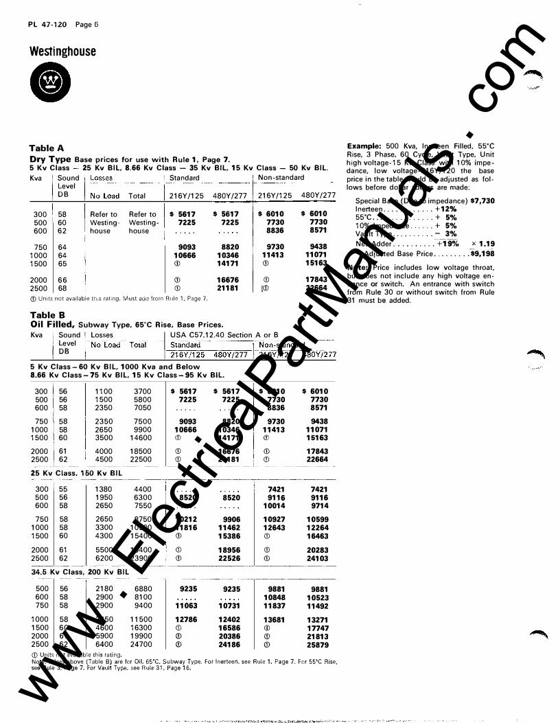
• Table A Dry Type Base prices for use with Rule 1, Page 7. 5 Kv Class 25 Kv BIL, 8.66 Kv Class - 35 Kv BIL, 15 Kv Class - 50 Kv BIL.
Kva Sound 1 Standard Non-standard Level DB �-�:ss
l:ad Total 216Y /125 480Y/277 I 216Y /125 480Y/277
300 58 Refer to Refer to $ 5617 $ 5617 $ 6010 $ 6010
500 60 Westing- Westing- 7225 7225 7730 7730
600 62 house house 8836 8571
750 64 9093 8820 9730 9438
1000 64 10666 10346 11413 11071
1500 65 (j) 14171 (j) 15163
2000 66 (j) 16676 (j) 17843
2500 68 (j) 21181 i<D 22664
(j) Units not available tt;,s rating. Must add from Rule 1. Page 7.
Table B Oil Filled, Subway Type, 65'C Rise, Base Prices.
Kva i Sound ! Losses I USA C57.12.40 Section A or B / �e�el INoload-roiaf-- ;�a;;J,r����80Y 1277 )--�-,<>;���;n0dar�80Y 1:7� 5 Kv Class-60 Kv BIL, 1000 Kva and Below 8.66 Kv Class-75 Kv BIL, 15 Kv Class-95 Kv BIL.
300 56 1100 3700 $ 5617 $ 5617 $ 6010 $ 6010 500 56 1500 5800 7225 7225 7730 7730 600 58 2350 7050 . . . . . .... . 8836 8571
750 58 2350 7500 9093 8820 9730 9438 1000 58 2650 9900 10666 10346 11413 11071 1500 60 3500 14600 (j) 14171 CD 15163
2000 61 4000 18500 (j) 16676 (j) 17843 2500 62
I 4500 22500 (j) 21181 i
(j) 22664 ---- -·- -25 Kv Class, 150 Kv BIL
-�··-·-·-
300 55 1380 4400 7421 7421 500 56 1950 6300 8520 8520 9116 9116 600 58 2650 7550 10014 9714
750 58 2650 8750 10212 9906 10927 10599 1000 58 3300 10500 11816 11462 12643 12264 1500 60 4300 15400 (j) 15386 (j) 16463
2000 61 5500 19400 CD 18956 (j) 20283 2500 62 6200 23900 (j) 22526 (j) 24103
34.5 Kv Class. 200 Kv BIL
500 56 2180 6880 9235 9235 9881 9881 600 58 2900 8100 10848 10523 750 58 2900 9400 11063 10731 11837 11492
1000 58 3650 11500 12786 12402 13681 13271 1500 60 4600 16300 CD 16586 (j) 17747 2000 61 5900 19900 (j) 20386 (j) 21813 2500 62 6400 24700 (j) 24186 (j) 25879
(j) Units not available this rating. Note: Prices above (Table B) are for Oil, 65'C. Subway Type. For lnerteen. see Rule 1, Page 7. For 55'C Rise. see Rule 3, Page 7. For Vault Type, see Rule 31, Page 16.
Example: 500 Kva, lnerteen Filled, 55'C Rise, 3 Phase, 60 Cycle, Vault Type, Unit high voltage-15 Kv Class with 10% impedance, low voltage-216Y /120 the base price in the table would be adjusted as follows before dollar adders are made;
Special Base (Due to impedance) $7,730 lnerteen .. . ..... . ... +12% 55'C . . .. . . . . . . . .. . . + 5% 10% Impedance . . ... + 5% Vault Type .. . ...... . - 3%
Net Adder . ........ . -+19% x 1.19
Adjusted Base Price . ... ... . . $9,198
Note: Price includes low voltage throat, but does not include any high voltage entrance or switch. An entrance with switch from Rule 30 or without switch from Rule 31 must be added.
www . El
ectric
alPar
tMan
uals
. com
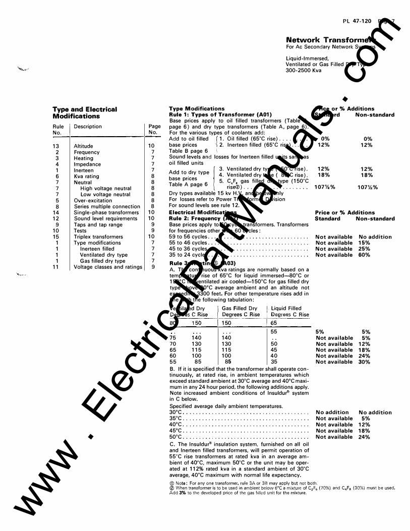
Type and Electrical Modifications
Rule I
Description Page No. No.
13 Altitude 10 2 Frequency 7 3 Heating 7 4 Impedance 7 1 lnerteen 7 6 Kva rating 8 7 Neutral 8 7 High voltage neutral 8 7 Low voltage neutral 8 5 Over- excitation 8 8 Series multiple connection 8
14 Single-phase transformers 10 12 Sound level requirements 10
9 Taps and tap range 9 10 Tests 9 15 Triplex transformers 10
1 Type modifications 7 1 lnerteen filled 7 1 Ventilated dry type 7 1 Gas filled dry type 7
11 Voltage classes and ratings 9
PL 47-120 Page 7
Network Transformers For Ac Secondary Network Systems
Liquid-Immersed, Ventilated or Gas Filled Dry-Type 300-2500 Kva
Type Modifications Rule 1: Types of Transformer (A01) Base prices apply to oil filled transformers {Table B, page 6) and dry type transformers {Table A, page 6). For the various types of coolants add: Add to oil filled ( 1. Oil filled (65'C rise) ....... . . base prices ) 2. lnerteen filled {65'C rise) ..... . Table B page 6 t
Sound levels and losses for lnerteen filled units same as oil filled units 1 3. Ventilated dry type {150'C rise). Add to dry type 4. Ventilated dry type { 80'C rise). base pnces 5. C F gas filled dry type {150'C Table A page 6 ri�e@) ................... . Dry types available 15 kv H.V. and below only For losses refer to Power Transformer Division For sound levels see rule 12. Electrical Modifications Rule 2: Frequency (A02) Base prices apply to 60 cycle transformers. Transformers for frequencies other than 60 cycles : 59 to 56 cycles . . . . . . . . . . . . . . . . . .. ........... . 55 to 46 cycles . . ....... ...................... . 45 to 36 cycles . . . . . . . . . . . . . . .... . ........... . 35 to 24 cycles .... ........................... .
Rule 3: Heating® {A03) A. The continuous kva ratings are normally based on a temperature rise of 65°C for liquid immersed-80°C or 150°C for ventilated air cooled-150°C for gas filled dry type above 30°C average ambient and an altitude not exceeding 3300 feet. For other temperature rises add in line with the following tabulation:
Ventilated Dry I Gas Filled Dry I Liquid Filled ��grees � 5
�ise ����-��-� �;grees C Rise
55 75 140 140 70 130 130 50 65 115 115 45 60 100 100 40 55 85 85 35 B. If it is specified that the transformer shall operate continuously, at rated rise, in ambient temperatures which exceed standard ambient at 30°C average and 40°C maximum in any 24 hour period, the following additions apply. Note increased ambient conditions of lnsuldur® system inC below. Specified average daily ambient temperatures. 30°C . . ........... ......... . ................ . 35°C ....................................... . 40°C .......... ............................. . 45°C .. , .. ,, .,, . . , . . , .. ,, .. ...... ....... . . . . . 50°C ... ..... ................... . ........ ... .
C. The lnsuldur® insulation system, furnished on all oil and lnerteen filled transformers, will permit operation of 55'C rise transformers at rated kva in an average am-bient of 4o·c. maximum 5o·c or the unit may be oper-ated at 112% rated kva in a standard ambient of 30'C average, 40'C maximum with normal life expectancy.
Price or % Additions Standard Non-standard
0% 0% 12% 12%
12% 12% 18% 18%
107%% 107%%
Price or % Additions Standard Non-standard
Not available No addition Not available 15% Not available 25% Not available 60%
5% Not available Not available Not available Not available Not available
No addition Not available Not available Not available Not available
5% 5%
12% 18% 24% 30%
No addition 5%
12% 18% 24%
(!) Note: For any one transformer, rule 3A or 3B may apply but not both. ® When transformer is to be used in ambient below 6'C a mixture of C2F6 (70%) and C4F8 {30%) must be used. Add 3% to the developed price of the gas f1lled unit for the mixture. www .
Elec
tricalP
artM
anua
ls . c
om
PL 47-120 Page 8
Westinghouse
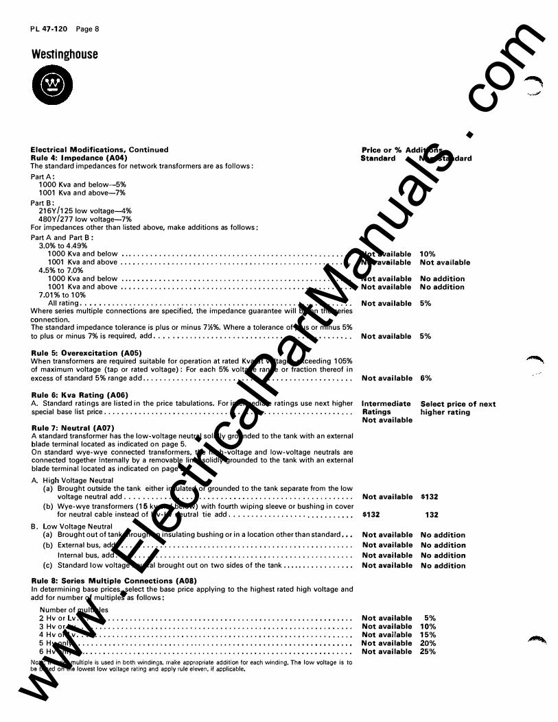
• Electrical Modifications, Continued Rule 4: Impedance (A04) The standard impedances for network transformers are as follows:
Part A: 1000 Kva and below-5% 1001 Kva and above-7%
Part B: 216Y /125 low voltage--4% 480Y /2771ow voltage-7%
For impedances other than listed above, make additions as follows:
Part A and Part B : 3.0% to 4.49%
1000 Kva and below • . • . . . . . • . . . . . . . • • . . . . . . . . . . . . . . . . . . . . . . . . . . . . . . . . . . . .
1 001 Kva and above . . . • . . . . . . . • . . . . . . • . . . . . . . . . . • • . . • . . • . . . . . . . . . . . . . . . • .
4.5%to 7.0% 1 000 Kva and below . • . . • • • • . • . . • • . . . . . . • . . . . . . . • . . . . . . . . . . • . . . . . . . • . . . . • .
1001 Kva and above • . • . . . . . . . . . . . . . • • . . . . . . • . . . . . . . • . . . . . . . • . • . . • . . . . . . . •
7.01%to 10% All rating . . • • • . • . . . . . . . . . . . . . . . . . . . . . . . . . . . . . . . . . . . . . . . . . . . . • . . . . . • . . . . .
Where series multiple connections are specified, the impedance guarantee will be on the series connection. The standard impedance tolerance is plus or minus 7Y.z%. Where a tolerance of plus or minus 5% to plus or minus 7% is required, add • . • . . • . . . . . . . • . • . . . • . • . • • . . . • • . • • . • . . . • . • . . • . .
Rule 5: Overexcitation (A05) When transformers are required suitable for operation at rated Kva at voltages exceeding 1 05% of maximum voltage (tap or rated voltage) : For each 5% voltage range or fraction thereof in excess of standard 5% range add . . . . . . . . . . . . . . . . . . . . . • . . . . . . • • . . • • . . . . . • . • • • . . . • .
Rule 6: Kva Rating (A06) A. Standard ratings are listed in the price tabulations. For intermediate ratings use next higher special base list price . . . . • . . • . . . . . • . . • . . . . . . • . . . . . . . . . . . . . . . . . . . . . . . . . . • . . • • . . .
Rule 7: Neutral (A07) A standard transformer has the low-voltage neutral solidly grounded to the tank with an external blade terminal located as indicated on page 5. On standard wye-wye connected transformers, the high-voltage and low-voltage neutrals are connected together internally by a removable link, solidly grounded to the tank with an external blade terminal located as indicated on page 5.
A. High Voltage Neutral (a) Brought outside the tank either insulated or grounded to the tank separate from the low
voltage neutral add . . . . . . . . . • . . . . . . . . . • . . . . • • . • . . • . . . . . . . . . . . . . . . . . . . . . .
(b) Wye-wye transformers (15 kv and below) with fourth wiping sleeve or bushing in cover for neutral cable instead of Hv-Lv neutral tie add . . . . . . . . . . . . . • . . . . . . . . . . . . • • •
B . low Voltage Neutral (a) Brought out of tank through an insulating bushing or in a location other than standard • • •
(b) External bus, add . . . . . . . . . . . . . . . . • . . . . . . . . . • . . . . . . • • . . • . . . . • . . • . . . . . . . . .
Internal bus, add . . . . . . . . . . . . . . . . . . . . . . . . . • • . . . . . . • • . . . . . . . . . . . . . . . . . . . .
(c) Standard low voltage neutral brought out on two sides of the tank . • • • • . . • • . . . . . . • •
Rule 8: Series Multiple Connections (A08) In determining base prices, select the base price applying to the highest rated high voltage and add for number of multiples as follows:
Number of multiples 2 Hv or lv . • . . . . . . . . • . . . . . . • . . • . . . . . • . • • . • . • • • • . . . . • • . . • . . • • . • • . • • • • • • • • . •
3 Hv or Lv . . . • . . . . . . . . . . . . . . • • . . . . . . , . . • . . . • • . . . . . . . . • • . . • . . . . . • . • • . • • . • • .
4 Hv or lv • . . . • . . . . . . . • . . . . . . . . . . . • • . . . . . . . . . • • . . • . . • . • . . • • . . • . . . . . , • • . . . •
5 Hv only • • . . • . • • . • . • . . . . . • . . . . • . . . . . . . . . . . . • • . • • . • • • • • • • . • • . • • • • • • • • • • • . •
6 Hv only • • . • • . . • . . . . . . . • . . . . . . . • . . . . . . . . . . . . . . • • . . • . . . • . . . • . • • • . • • • • . • . . •
Note: It series multiple is used in both windings, make appropriate addition for each winding, The low voltage is to be based on the lowest low voltage rating and apply rule eleven. it applicable.
Price or % Additions Standard Non-standard
Not available 10% Not available Not available
Not available No addition Not available No addition
Not available 5%
Not available 5%
Not available 6%
Intermediate Ratings Not available
Not available
$132
Not available
Not available
Not available
Not available
Not available Not available Not available Not available Not available
Select price of next higher rating
$132
132
No addition
No addition
No addition
No addition
5% 10% 15% 20% 25%
www . El
ectric
alPar
tMan
uals
. com
PL 47-120 Page 9
Network Transformers For Ac Secondary Network Systems
Liquid-Immersed, Ventilated or Gas Filled Dry-Type 300-2500 Kva
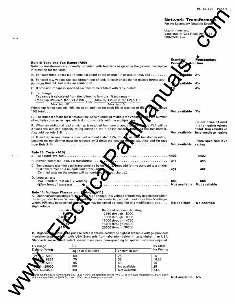
Standard Nonstandard Rule 9: Taps and Tap Range (A09) Price or % Addition Network transformers are normally provided with four taps as given in the general descriptive information for the units.
A. For each three-phase tap to terminal board or tap changer in excess of four, add. . . . . . . . . Not available 2%
B. For each low voltage tap lead brought out of tank for each phase do not make a further addi-tion from Rule 9A, but make an addition of . . . . . . . . . . . . . . . . . . . . . . . . . . . . . . . . . . . . . . . . . Not available 4%
C. If omission of taps is specified on transformers listed with taps, deduct . • . . . . . . . . . . . . . . .
D. Tap Range Tap range is calculated from the following formula: %tap range= (Max. tap H�-=:11'1i��tap HV) X100
plus (Max. tap �V-min. tap LV) X1 00
Max. tap HV Max. tap LV Where tap range exceeds 1 0%, make an addition for each 5% or fraction of 5% of range above
4% 4%
10% total . . . . . . . . . . . . . . . . . . . . . . . . . . . . . . . . . . . . . . . . . . . . . . . . . . . . . . . . . . . . . . . . . . . Not available 3%
E. The number of taps for series multiple is the number of multiple tap voltages times the number of multiples plus series taps which do not coincide with the multiple taps.
F. When an additional load at mid tap is required from one phase, the total pricing KVA will be 3 times the reduced capacity rating added to the 3 phase capacity rating of the transformer. Also add per rule 9- B.... . . . . . . . . . . . . . . . . . . . . . . . . . . . . . . . . . . . . . . . . . . . . . . . . . . . . . . Not available
G. If mid tap in one phase is specified without stated KVA, do not increase transformer rating. Loading on transformer must be reduced by 3 times the loading on the tap. Also add for taps from Rule 9-B. . . . . . . . . . . . . . . . . . . . . . . . . . . . . . . . . . . . . . . . . . . . . • . . . . . . . . . . . . . . . . . Not available
Rule 10: Tests (A10) A. For sound level test . . . . . . . . . . . . . . . . . . . . . . . . . . . . . . . . . • . . . . . . . . . . • • • . • . . • . • . • . $402
B. Power factor test-add, per transformer . . . . . . . . . . . . . . . . . . . . . . . . . . . . . . . . . . • . • • • • • 344
C. Temperature test-for each transformer to be tested, (Do not add for the standard test on the first transformer on a multiple unit order) add . . . . . . . . . . . . . . . . . • . . . . . . . . . . . . . . . . . . 402 (Certified tests on the design will be furnished without charge.)
D. Impulse test:
Select price of next higher rating where total Kva results in intermediate rating
Price specified Kva rating
$402
344
402
USA Standard test on Hv winding . . . . . . . . . . . . . . . . . . . . . . . . . . . . . . . . . . . . . . . . . . . . 688 688
NEMA front of wave test .... ... ... . .. . .... . ... . . . ... . . .. . .............. . ... . Not available Not available
Rule 11: Voltage Classes and Ratings (A11) A. Optional voltage ratings for either the high voltage, low voltage or both may be selected within the range listed below. Where high voltage option is selected, a total of not more than 5 voltages within 1 0% may be specified and any one may be named as rated. For this modification, add . . . . No addition No addition High voltage
Insulation class 5 Kv
8.66 Kv 15 Kv 25 Kv
34.5 Kv
Range of optional Hv rating 21 60 through 5000 6600 through 8660
11000 through 14750 16400 through 24600 25700 through 36200
B. High voltage class-The price selected is determined by the highest available voltage, provided insulation tests conform with USA Standards from tabulation below. If tests higher than USA Standards are required, select special base price corresponding to special test class required.
Hv Range Kv Class Delta or Wye or Gas Filled for Pricing
2150- 5000 60 25 5 5001- 8667 75 35 8.66 8668-15000 95 50 15
15001-25000 150 No available 25 25001-34500 200 Not available 34.5
Note: Where liquid transformers 5001-8667 volts are specified for 95KV Bl L. or dry type transformers 5001-8667 volts are specified for 50KV Bl L. use 15KV special base price and add............................................ Not available 5%
www . El
ectric
alPar
tMan
uals
. com
PL 47-120 Page 10
Westinghouse
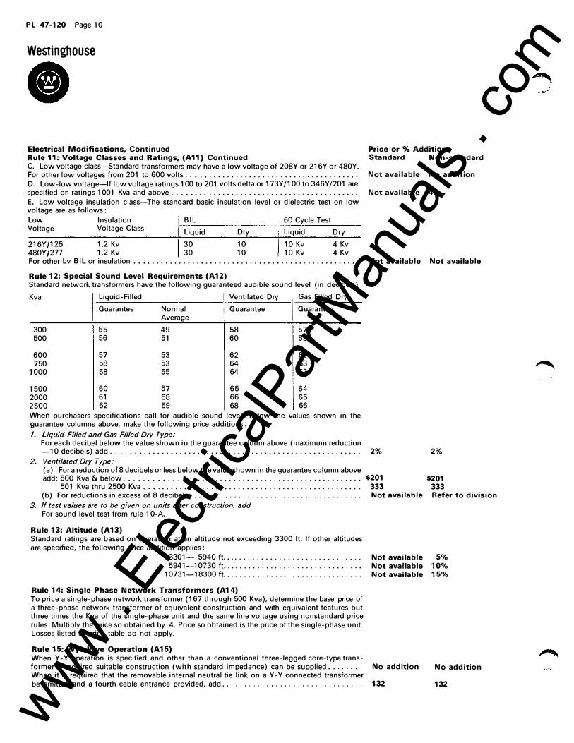
• Electrical Modifications, Continued Rule 11: Voltage Classes and Ratings, (A11) Continued C. Low voltage class-Standard transformers may have a low voltage of 208Y or 216Y or 480Y. For other low voltages from 201 to 600 volts . . • . . . . . . . . . . . . . . . . . . . . . . . . . . . . . . . . . . . . D. Low-low voltage-If low voltage ratings 1 00 to 201 volts delta or 173Y /1 00 to 346Y /201 are specified on ratings 1 001 Kva and above ......................................... .
E. Low voltage insulation class-The standard basic insulation level or dielectric test on low voltage are as follows: Low Insulation , BIL 60 Cycle Test 1-··----------Voltage Voltage Class 1 Liquid Dry Liquid Dry
��g����� �:��� I �g �g I �g�� :�� For other Lv BIL or insulation . . . . . . . . . . . . . . . . . . . . . . . . . . • . . . . . • . . . . . . . . . . . . . . . . • .
Rule 12: Special Sound Level Requirements (A12) Standard network transformers have the following guaranteed audible sound level (in decibels) Kva I Liquid-Filled I Ventilated Dry ��s Filled Dry
Guarantee Normal 1 Guarantee Guarantee Average
300 55 49 58 57 500 56 51 60 59
600 57 53 62 62 750 58 53 64 63
1000 58 55 64 63
1500 60 57 65 64 2000 61 58 66 65 2500 62 59 68 66 When purchasers specifications call for audible sound levels below the values shown in the guarantee columns above, make the following price additions: 1. Liquid-Filled and Gas Filled Dry Type:
For each decibel below the value shown in the guarantee column above (maximum reduction -10 decibels) add . . . . . . . . . . . . . . . . . . . . . . . . . . . . . . . . . . . . . . . . . . . . . . . . . . . . . . . .
2. Ventilated Dry Type: (a) For a reduction of 8 decibels or less below the value shown in the guarantee column above add: 500 Kva & below . . . . . . . . . . . . . . . . . . . . . . . . . . . . . . . . . . . . . . . . . . . . . . . . . . .
501 Kva thru 2500 Kva ................................................ . (b) For reductions in excess of 8 decibels • . . . . . . . . . . . . . . . . . . . . . . . . . . . . . . . . . . . . . .
3. If test values are to be given on units after construction, add For sound level test from rule 1 0-A.
Rule 13: Altitude (A13) Standard ratings are based on operation at an altitude not exceeding 3300 ft. If other altitudes are specified, the following price addition applies:
3301 5940 ft ............................... . 5941-10730 ft ................ ' . . . . . . . . . . . . . . .
10731-18300 ft ............................... .
Rule 14: Single Phase Network Transformers (A14) To price a single-phase network transformer (167 through 500 Kva), determine the base price of a three-phase network transformer of equivalent construction and with equivalent features but three times the Kva of the single-phase unit and the same line voltage using nonstandard price rules. Multiply the price so obtained by .4. Price so obtained is the price of the single-phase unit. Losses listed in price table do not apply.
Rule 15: Wye-Wye Operation (A15) When Y-Y operation is specified and other than a conventional three-legged core-type trans-
Price or % Additions Standard Non-standard
Not available No addition
Not available 4%
Not available Not available
2% 2%
$201 $201 333 333 Not available Refer to division
Not available 5% Not available 10% Not available 15%
former is required suitable construction (with standard impedance) can be supplied . . . . . . . No addition No addition When it is required that the removable internal neutral tie link on a Y-Y connected transformer be omitted and a fourth cable entrance provided, add . . . . . . . . . . . . . . . . . . . . . . . . . . . . . . . . 132 132
�
www . El
ectric
alPar
tMan
uals
. com
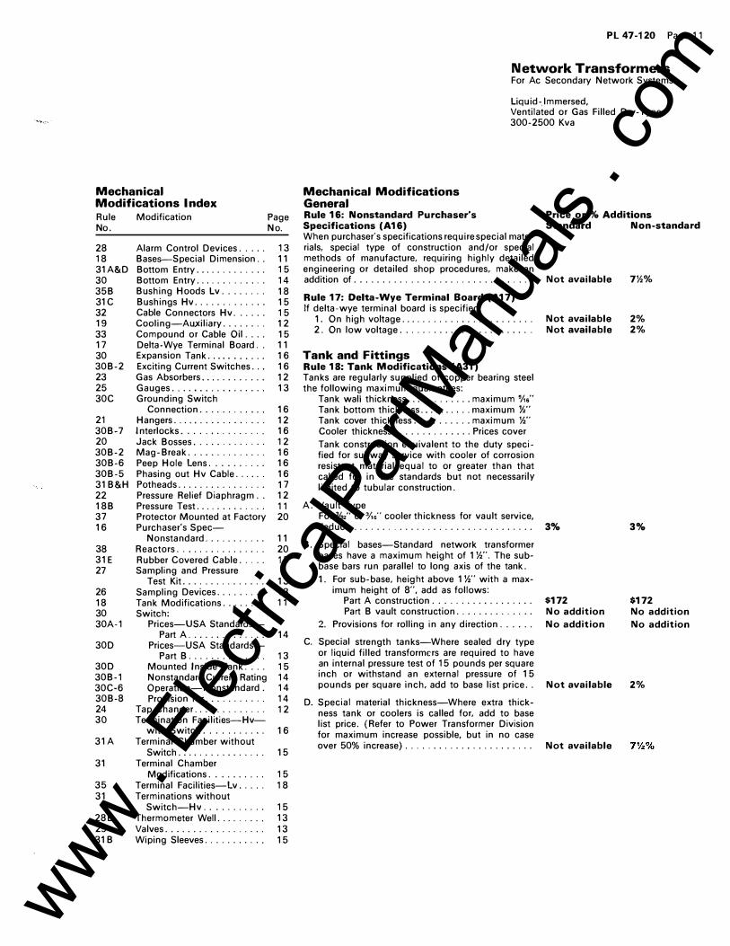
Mechanical Modifications Index Rule No.
28 18 31A&D 30 35B 31C 32 19 33 17 30 30B-2 23 25 30C
21 30B-7 20 30B-2 30B-6 30B-5 31B&H 22 18B 37 16
38 31E 27
26 18 30 30A-1
30D
30D 30B-1 30C-6 30B-8 24 30
31A
31
35 31
28B 29 31 B
Modification Page No.
Alarm Control Devices. . . . . 13 Bases--Special Dimension. . 11 Bottom Entry. . . . . . . . . . . . . 1 5 Bottom Entry. . . . . . . . . . . . . 14 Bushing Hoods Lv. . . . . . . . 18 Bushings Hv. . . . . . . . . . . . . 15 Cable Connectors Hv. . . . . . 15 Cooling-Auxiliary. . . . . . . . 12 Compound or Cable Oil . . . . 15 Delta-Wye Terminal Board. . 11 Expansion Tank. . . . . . . . . . . 16 Exciting Current Switches. . . 16 Gas Absorbers. . . . . . . . . . . . 12 Gauges.......... ....... 13 Grounding Switch
Connection. . . . . . . . . . . . 16 Hangers......... . . . . . . . . 12 Interlocks............... 16 Jack Bosses. . . . . . . . . . . . . 12 Mag-Break. . . . . . . . . . . . . . 16 Peep Hole Lens. . . . . . . . . . 16 Phasing out Hv Cable. . . . . 16 Potheads . . . . . . . . . . . . . . . . 1 7 Pressure Relief Diaphragm . . 12 Pressure Test. . . . . . . . . . . . . 11 Protector Mounted at Factory 20 Purchaser's Spec-
Nonstandard . . . . . . . . . . . 11 Reactors. . . . . . . . . . . . . . . . 20 Rubber Covered Cable. . . . . 1 5 Sampling and Pressure
Test Kit............... 13 Sampling Devices. . . . . . . . . 13 Tank Modifications.... . . . . 11 Switch:
Prices-USA Standards-Part A. . . . . . . . . . . . . 14
Prices-USA Standards-Part B. . . . . . . . . . . . 13
Mounted Inside Tank. . . . 15 Nonstandard Current Rating 14 Operation-Nonstandard . 14 Provision for. . . . . . . . . . 14
Tap Changer. . . . . . . . . . . . . 12 Termination Facilities--Hv-
with Switch . . . . . . . . . . . 16 Terminal Chamber without
Switch................ 15 Terminal Chamber
Modifications. . . . . . . . . . 15 Terminal Facilities-Lv.. . . . 18 Terminations without
Switch-Hv. . . . . . . . . . . 15 Thermometer Well. . . . . . . . . 13 Valves. . . . . . . . . . . . . . . . . . 13 Wiping Sleeves. . . . . . . . . . . 15
Pl47-120 Page 11
Network Transformers For Ac Secondary Network Systems
Liquid-.lmmersed, Ventilated or Gas Filled Dry-Type 300-2500 Kva
Mechanical Modifications General Rule 16: Nonstandard Purchaser's Specifications (A16) When purchaser's specifications require special materials, special type of construction and/or special methods of manufacture, requiring highly detailed engineering or detailed shop procedures, make an addition of ............................... .
Rule 17: Delta-Wye Terminal Board (A17) If delta-wye terminal board is specified:
1. On high voltage ....................... . 2. On low voltage. . . . . . . . . . . ........... .
Tank and Fittings Rule 18: Tank Modifications (A31) Tanks are regularly supplied of copper bearing steel the following maximum guarantees:
Tank wall thickness ............ maximum "A6' Tank bottom thickness .......... maximum }/," Tank cover thickness .......... maximum %" Cooler thickness .............. Prices cover
Tank construction equivalent to the duty specified for subway service with cooler of corrosion resistant material equal to or greater than that called for in the standards but not necessarily limited to tubular construction.
A. Vault Type For %2' or 3/,6' cooler thickness for vault service, deduct. . . . . . . . ....................... .
B. Special bases-Standard network transformer bases have a maximum height of 1 %". The subbase bars run parallel to long axis of the tank.
1. For sub-base, height above 1 %" with a maximum height of 8", add as follows:
Part A construction ................. . Part B vault construction ............. .
2. Provisions for rolling in any direction ..... .
C. Special strength tanks-Where sealed dry type or liquid filled transformers are required to have an internal pressure test of 15 pounds per square inch or withstand an external pressure of 15 pounds per square inch, add to base list price ..
D. Special material thickness-Where extra thickness tank or coolers is called for. add to base list price. (Refer to Power Transformer Division for maximum increase possible, but in no case over 50% increase} ...................... .
Price or % Additions Standard Non-standard
Not available
Not available Not available
3%
$172 No addition
No addition
Not available
Not available
7%%
2% 2%
3%
$172 No addition
No addition
2%
www . El
ectric
alPar
tMan
uals
. com
PL47-1 20 Page 1 2
Westinghouse
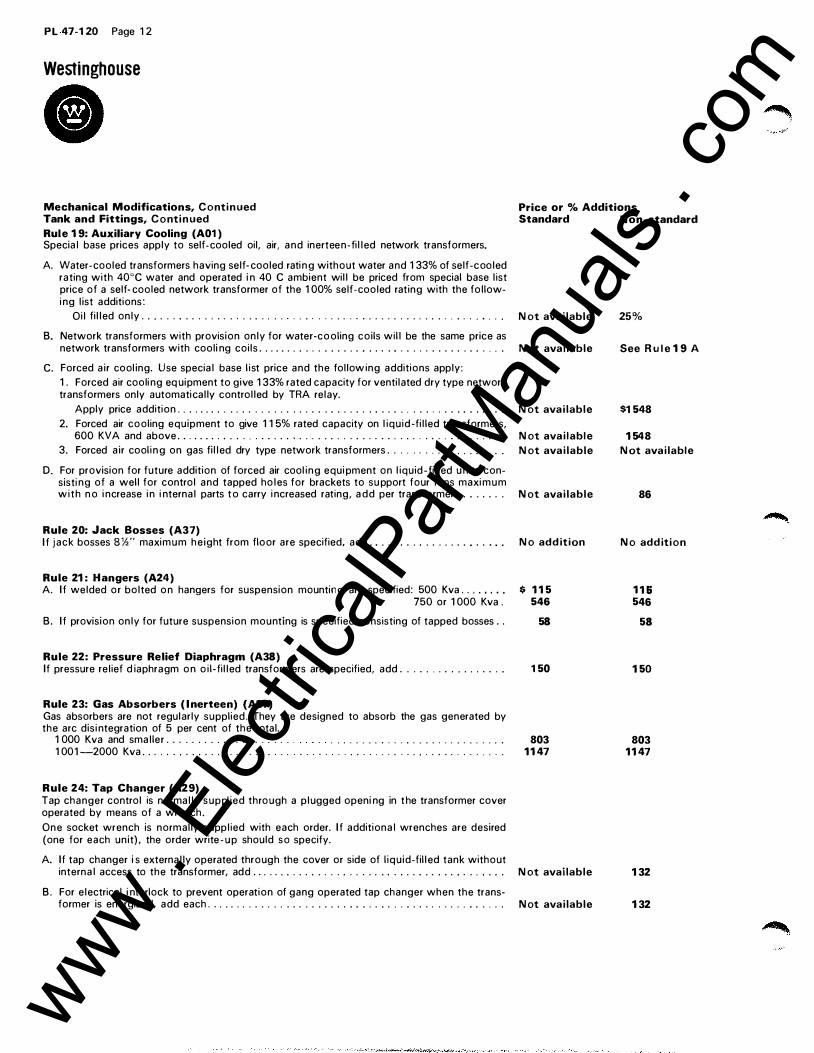
• Mechanical Modifications, Continued Tank and Fittings, Continued
Rule 19: Auxiliary Cooling (A01 ) Special base prices apply to self-cooled oil, air, and inerteen-filled network transformers.
A. Water-cooled transformers having self- cooled rati n g without water and 1 33% of self -cooled rating with 40°C water and operated i n 40 C ambient will be priced from special base list price of a self- cooled network transformer of the 1 00% self-cooled rating with the followi ng list additions:
Oil filled only . . . . . . . . . . . . . . . . . . . . . . . . . . . . . . . . . . . . . .. . . ... . . . .. . . . .. . .
B. Network transformers with provision only for water-cooling coils will be the same price as network transformers with cooli ng coils . .. . . .. . .. .. . . . . . .. . . . .. . . . .. . . . . .. . . .. .
C. Forced air cooling. Use special base l ist price and the follow ing additions apply: 1 . Forced air cooli ng eq uipment to give 1 33% rated capacity for ventilated dry type network transformers only automatically controlled by TRA relay.
Apply price addition . .. . . .. . ... . . . . .. . . . . .. . ... . . . . . .. . . . .. . . . . . . . ... ... .
2. Forced air cooling equipment to give 1 1 5% rated capacity on l iquid -filled transformers, 600 KVA and above . . .. . . . . . .. . . . . . . . . ... .... .... .. .. . . ... ... . .. ....... .
3. Forced air cool i n g on gas filled dry type network transformers . . .... . . . . . . . .. . . . .
D. For provision for future addition of forced air cooling equi pment on l iquid-filled u nits consisti ng of a well for control and tapped holes for brackets to su pport four fans maxi m u m w i t h no i ncrease i n i nternal parts t o carry i ncreased rating, a d d per transformer .. ... . . .
Rule 20: Jack Bosses (A37) If jack bosses 8%" maxim u m height from floor are specified, add . .. . . . . . .. . . . . . . .. . .. .
Rule 21: Hangers (A24) A. If welded or bolted on hangers for suspension mounting are specified: 500 Kva . . . . . . • .
750 or 1 000 Kva .
B. If provision only for future suspension mounting is specified consisting of tapped bosses ..
Rule 22: Pressure Relief Diaphragm (A38) If pressure relief d iaphragm on oi l-filled transformers are specified, add . . . . . .. . .... . . . . .
Rule 23: Gas Absorbers ( l nerteen) {A21) Gas absorbers are not regularly supplied. They are designed to absorb the gas generated by the arc disi ntegration of 5 per cent of the total.
1 000 Kva and smaller . . . . . . . . . . . . . . . . . . . . .. . . . . . . . . . . . . . . . . . . . . .... . 1 001 -2000 Kva . . . . . . . . . . . . . . . . . . . . . . . . . . . . . . . . . . . . . . . . . . . . . . . . . . . . . . . . .
Rule 24: Tap Changer (A29) Tap changer control is normally supplied through a plugged openi ng in t he transformer cover operated by means of a wrench. One socket wrench is normally supplied with each order. If additional wrenches are desired (one for each unit), the order write - u p should so specify.
A. If tap changer i s externally operated through the cover or side of l iquid-filled tank without
Price or % Additions Standard N on-standard
Not available
Not available
Not available
Not available
Not available
Not available
No addition
$ 115 546
58
1 50
803 1147
25%
See Rule 19 A
$1 548
1548
Not available
86
No addition
11& 546
58
150
803 1147
internal access to the transformer, add . . . . . . . . . . . . . . . . . . . . . . . . . . . . . . . . . . . . . . . . . Not available 132
B. For electrical i nterlock to prevent operation of gang operated tap changer when the trans-former is energized, add each . . . . . . . . . . . . . . . . . . . . . . . . . . . . . . . . . . . . . . . . . . . . . . . . Not available 132
www . El
ectric
alPar
tMan
uals
. com
PL 47-120 Page 13
Network Transformers For Ac Secondary Network Systems
Liquid-Immersed, Ventilated or Gas Filled Dry-Type 300-2500 Kva
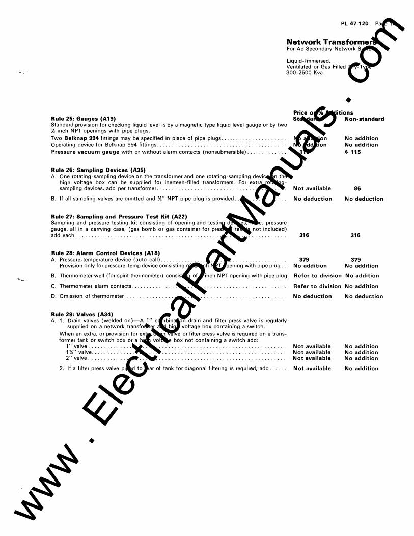
Rule 25: Gauges (A19) Standard provision for checking liquid level is by a magnetic type liquid level gauge or by two Y,. inch NPT openings with pipe plugs.
Two Belknap 994 fittings may be specified in place of pipe plugs .................... . Operating device for Belknap 994 fittings ...................................... .
Pressure vacuum gauge with or without alarm contacts (nonsubmersible) ............ .
Rule 26: Sampling Devices (A35) A. One rotating-sampling device on the transformer and one rotating-sampling device on the
high voltage box can be supplied for inerteen-filled transformers. For extra rotating-sampling devices, add per transformer ............. ........................... .
B. If all sampling valves are omitted and %" NPT pipe plug is provided ................ .
Rule 27: Sampling and Pressure Test Kit (A22) Sampling and pressure testing kit consisting of opening and testing devices, hose, pressure gauge, all in a carrying case, (gas bomb or gas container for pressure test is not included) add each . . . . . . . . . . . . . . . . . . . . . . . . . . . . . . . . . . . . . . . . . . . . . . . . . . . . . . . . . . . . . . . . . .
Rule 28: Alarm Control Devices (A18) A. Pressure-temperature device (auto-call) ....................................... .
Provision only for pressure-temp device consisting of% inch NPT opening with pipe plug ..
Price or % Additions Standard Non-standard
No addition No addition
$ 115
Not available
No deduction
316
379 No addition
No addition No addition
$ 115
86
No deduction
316
379 No addition
B. Thermometer well (for spirit thermometer) consisting of% inch N PT opening with pipe plug Refer to division No addition
C. Thermometer alarm contacts .................................. .
D. Omission of thermometer ................................... .
Rule 29: Valves (A34) A. 1. Drain valves (welded on)-A 1" combination drain and filter press valve is regularly
supplied on a network transformer and high voltage box containing a switch.
When an extra, or provision for extra drain valve or filter press valve is required on a transformer tank or switch box or a high voltage box not containing a switch add:
1" valve ............................................................. . 1 %"valve............................................ . . ... . . . . . . . .
2" valve . . . . .. . . . . . .... . . . . . . . . .. . · . . · . · . · . · · · · · · · · · · · · · · · · · · · · · · · · · · ·
2. If a filter press valve piped to rear of tank for diagonal filtering is required, add ..... .
Refer to division No addition
No deduction
Not available Not available Not available
Not available
No deduction
No addition No addition No addition
No addition
www . El
ectric
alPar
tMan
uals
. com
PL 47-120 Page 1 4
Westinghouse
• Mechanical M odifications, Continued
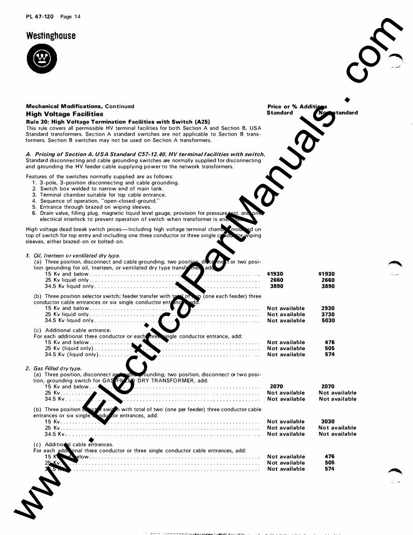
H igh Voltage Facilities Rule 30: High Voltage Termination Facilities with Switch (A25) This rule covers all permissible HV terminal facil ities for both Section A and Section B. USA Standard transformers. Section A standard switches are not appl i cable to Section B transformers. Section B switches may not be used on Section A transformers.
A. Pricing of Section A. USA Standard C57- 12.40, HV terminal facilities with switch. Standard disconnecting and cable grounding switches are normally su pplied for disconnecti ng and g round i n g the HV feeder cable supplying power to the network transformers.
Features of the switches normally s uppl ied are as follows: 1 . 3 -pole, 3 - position disconnecting and cable grounding. 2. Switch box welded to narrow end of main tank. 3. Terminal chamber suitable for top cable entrance. 4. Sequence of operation, "open-closed -ground." 5. Entrance through brazed on wiping sleeves. 6. Drain valve, f i l l ing plug. magnetic l iq u id level ga uge, provision for pressure test, and one
electrical interlock to prevent operation of switch w h e n transformer is energized.
H ig h voltage dead break switch prices-Including high voltage terminal chamber mounted on top of switch for top entry and i n c l uding one three conductor or three single conductor wiping sleeves, either brazed -on or bolted -on.
1. Oil, lnerteen or ventilated dry type. ( a ) Three position, disconnect and cable grounding; two position, disconnect or two posit ion grounding for oi l , l nerteen, or venti lated dry type transformers add:
1 5 Kv and below . . . . . . . . . . . . . . . . . . . . . . . . . . . . . . . . . . . . . . . . . . . . . . . . . . . 25 Kv l i q u id o n ly . . . . . . . . . . . . . . . . . . . . . . . . . . . . . . . . . . . . . . . . . . . . . . . . . . . . . .
34.5 Kv l iqu id o n l y . . . . . . . . . . . . . . . . . . . . . . . . . . . . . . . . . . . . . . . . . . . . . . . . . . . .
( b ) Three position selector switch; feeder transfer with total of two (one each feeder) three conductor cable entrances or six single cond uctor entrances add:
1 5 Kv and below . . . . . . . . . . . . . . . . . . . . . . . . . . . . . . . . . . . . . . . . .
25 Kv l iq u id only . . . . . . . . . . . . . . . . . . . . . . . . . . . . . . . . . . . . . . . . . . . . . . . . . . . . . .
34.5 Kv l iquid o n l y . . . . . . . . . . . . . . . . . . . . . . . . . . . . . . . . . . . . . . . .
(c) Additional cable entrance: For each additional thre e conductor or each three single conductor entrance, add:
1 5 Kv and below . . . . . . . . . . . . . . . . . . . . . . . . . . . . . . . . . . . . . . . . . . . . . . . . . . . . . 25 Kv ( l iqu id only) . . . . . . . . . . . . . . . . . . . . . . . . . . . . . . . . . . . . . . . . . . . . . . . . . . .
34.5 Kv ( liquid o n ly ) . . . . . . . . . . . . . . . . . . . . . . . . . . . . . . . . . . . . . . . . . . . . . . .
2. Gas Filled dry type. (a) Three position, disconnect and cable grounding; two position, discon nect or two posit ion, grounding switch for GAS FI LLED D RY TRANSFO R M ER, add:
1 5 Kv and below . . . . . . . . . . . . . . . . . . . . . . . . . . . . . . . . . . . . . . . . . . . . . . . . . . . . . . 25 Kv . . . . . . . . . . . . . . . . . . . . . . . . . . . . . . . . . . . . . . . . . . . . . . . . . . . . . . . . . . . . . .
34.5 Kv . . . . . . . . . . . . . . . . . . . . . . . . . . . . . . . . . . . . . . . . . . . . . . . . . . . .
( b) Three position selector switch with total of two (one per feeder) three conductor cable entrances or six s i ngle conductor entrances, add:
1 5 Kv . . . . . . . . . . . . . . . . . . . . . . . . . . . . . . . . . . . . . . . . . . . . . . . . . . . . . . . . . . . . . . .
25 Kv . . . . . . . . . . . . . . . . . . . . . . . . . . . . . . . . . . . . . . . . . . . . . . . . . . . . . . . . . . . . . . 34.5 Kv . . . . . . . . . . . . . . . . . . . . . . . . . . . . . . . . . . . . . . . . . . . . . . . . . . . . . . . . . .
( c ) Addit ional cable entrances. For each additional three conductor or three single conductor cable entrances, add:
1 5 Kv and below . . . . . . . . . . . . . . . . . . . . . . . . . . . . . . . . . . . . . . . . . . . . . . . . . 25 Kv . . . . . . . . . . . . . . . . . . . . . . . . . . . . . . . . . . . . . . . . . . . . . . . . . . . . . . . . . . . . . . 34.5 Kv . . . . . . . . . . . . . . . . . . . . . . . . . . . . . . . . . . . . . . . . . . . . . . . . . . . . . . . . . . . . .
Price or % Additions Standard Non-standard
$1930 2660 3890
N ot ava i lable N o t available N ot avai lable
N ot ava i lable N ot ava i lable N ot avai lable
2070 N o t ava i lable N ot avai lable
N ot available N ot avai lable N ot ava i lable
N ot avai lable N ot ava i lable Not available
$1 930 2660 3890
2930 3730 5030
476 505 574
2070 N ot ava i lable N ot ava i l able
3030 N o t available Not avai lable
476 505 574
www . El
ectric
alPar
tMan
uals
. com
PL 47-1 20 Page 1 5
Network Transformers For Ac Secondary Network Systems
Liquid - Im mersed, Ventilated or Gas Fi l led D ry -Type 300-2500 Kva
Rule 30: High Voltage Termination Facilities with Switch (A25), Continued
B. Optional modifications for which separate additions are required.
Price or % Additions Standard Non-standard
1. Higher current rating s witches Switches are normally 200 Amperes. If higher capacity switch is req u i red, 1 5 Kv and below, add to switch price :
400 Amperes . . . . . . . . . . . . . . . . . . . . . . . . . . . . . . . . . . . . . . . . . . . . . . . . . . . . . . . .
600 Amperes . . . . . . . . . . . . . . . . . . . . . . . . . . . . . . . . .
H ig her capacity switches are not avai lable above 1 5 Kv.
2. Switches to break exciting cu11ent. When a switch is requ i re d to break exciting c u rrent an extra i nterlock is req u i red to prevent breaking l o ad c urrent. The i nterlock is supplied from the network protector with leads being brought through the protector mounting throat. Qu ick- break mechanism is su pplied for
N ot available Not ava i lable
rapidly extinguishing the arc. For this arrangement, add to switch price . . . . . . . . . . . . . . . $ 230
3. Provisions for alternate cable entrance. When o n ly one set of cables are to be connected at one time and openings are provided i n the sides o f the H v terminal chamber with cover plates t o permit a n alternate ch oice of entrance by interchanging with the top plate which has wiping sleeves and where only one entrance wil l be used at a time, add as follows:
(a) Entry provision i n one side . . . . . . . . . . . . . . . . . . . . . . . . . . . . . . . . . . . . . . . . . . . . . . Not avai lable
( b ) Entry provisions in two sides . . . . . . . . . . . . . . . . . . . . . . . . . . . . . . . . . . . . . . . . . . . . . N o t avai lable
( c ) I f provision is made for use of one 3 - phase or 3 single- phase cond uctors, but both entrances are in standard location on top of terminal chamber; this may be d one by provid i n g a larger opening f o r the center cable with t h e other two openings standard size . . . . . . . . 1 1 5
( d ) Pothead entrance i n terminal chamber for 3 single cond uctor cables from above . . . . 1 72
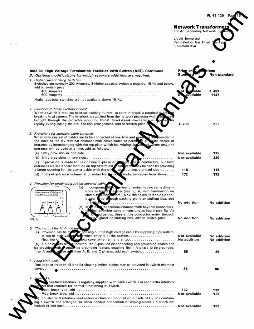
4. Provision for terminating rubber co vered cable. ( a ) I n compo u nd f i l led terminal c ha mber having same d i m e n -
o.mensions of 15Kvltqu•d sions as l iqu id chamber ( see fig. A) with termi n ation on t.tled terminol chamber clamp-type connectors, 1 5 Kv and below, three single con-
10� d u ctor entry through packing gland or stuffing box, add -�h J to switch price . . . . . . . . . . . . . . . . . . . . . . . . . . . . . . . . . No addition
( b) In a ir insu lated terminal chamber with bayonet connectors, terminal chamber same d i mensions as l iqu id (see fig. A) 1 5 Kv and below, three single cond uctor entry through
F I G . A packing gland or stuffing box, add to switch price . . . . No addition
5. Phasing out the high voltage cable. ( a ) Provision can be made for phasing out the h igh voltage cable by su pplying pipe outlets.
In top of high voltage box when entry is at the bottom . . . . . . . . . . . . . . . . . . . . . . . . Near top of h i g h voltage box cover when entry is at top . . . . . . . . . . . . . . . . . . . . . .
( b ) If p i pe outlets are not desired, the 3- position discon necting and grounding switch can b e provided with a sequence grounding feature, enabling f irst-A phase to be grounded, then A and B phase and then A, B, and C p hases, add each switch . . . . . . . . . . . . . . . . .
6. Peep Hole Lens. One large or three small lens for viewing switch blades may be provided in switch chamber cover . . . . . . . . . . . . . . . . . . . . . . . . . . . . . . . . . . . . . . . . . . . . . . . . . . . . . . . . . . . . . . . . . . .
7. Interlocks. (a) O n e electrical i nterlock i s regularly su pplied with each switch. For each extra interlock beyond that requ i red for normal functioning of switch.
Dead- break type, add . . . . . . . . . . . . . . . . . . . . . . . . . . . . . . . . . . . . . . . . . . . . . . . . . . . Mag-break type, add . . . . . . . . . . . . . . . . . . . . . . . . . . . . . . . . . . . . . . . . . . . . . . . . . . .
( b ) For electrical i nterlock lead entrance chamber mounted o n outside of Hv box conta i n ing a switch and arranged f o r either cond u it connection or w i p i n g sleeve ( i nterlock not i ncluded) add each . . . . . . . . . . . . . . . . . . . . • . . . . . . . . . . . . . . . . . . . . . . . . . . . . . . . . . . .
N ot avai lable No addition
86
86
1 32 N ot avai lable
N o t available
$ 459 1 1 47
23)
1 1 5
230
1 1 5
1 72
N o addition
No addition
No addition No addition
86
86
1 32 1 32
1 32 www . El
ectric
alPar
tMan
uals
. com

P L 47-1 20 Page 1 6
Westinghouse
• Mechanical Modifications, Conti nued Rule 30-B: High Voltage Termination Facilities with Switch (A25), Cont i n ued
(c) Flags and necessary peep holes to show position of the electrical i nterlock o n the g rounding switch or electrical means for external i nd ication . . . . . . . . . . . . . . . . . . .
(d ) For mechanical or electrical interlock between g a ng operated ta p changer and g rounding switch handle add each . . . . . . . . . . . . . . . . . . . . . . . . . . . . . . . . . . . . . . .
8. Provision only for switch.
If a transformer is to be provided for a switch, but the switch is not s upplied with the transformer; make the following addition: (Consisting of switch chamber and Hv terminal chamber without switch parts) . . . . . . . .
9. Provision for Switch Not Westinghouse.
When it i s necessary to make provisions for a switch not of Westingh ouse manufacture, add
10. Where pothead entrance is furnished in l ie u of a terminal chamber for terminating customer's cable; the terminal chambe r and wiping sleeves would be completely omitted . . . . . . . . .
1 1. L iquid level gauge on high voltage terminal chamber . . . . . . . . . . . . . . . . . . . . . . . . . . . . .
12. Expansion Tank
A. An expansion tank for o i l f i l led h i g h voltage box complete with o i l gauge a nd mounted o n
t h e h igh voltage b o x add . . . . . . . . . . . . . . . . . . . . . . . . . . . . . . . . . . . . . . . . . . . . . . . . . .
B. Provision for expansion of o i l in Hv terminal chamber consisting of standpipe extending above the chamber . . . . . . . . . . . . . . . . . . . . . . . . . . . . . . . . . . . . . . . . . . . . . . . . . . . . . . . .
C. Optional modifications requiring a single adder.
When one or more of the fol lowing o ptional modifications are requ ired, make a single addi -tion o f . . . . . . . . . . . . . . . . . . . . . . . . . . . . . . . . . . . . . . . . . . . . . . . . . . . . . . . . . . . . . . . . . . . .
1 . Switch mounted on long side of tank.
2. Bottom entry of high voltage cable.
3 . Removable o r flange mounted Westin ghouse switch.
4. Switch operating handle on l eft side or on both sides i n stead of on the rig ht side which is
standard.
5. Ground connection to be brou g h t out of the box through porcelain bushings and an external strap provided to connect and ground the bushing studs to the tank wal l i n stead of the standard g ro u nd connections made i n side the switch compartment.
6. Terminal chamber with d imensions greater than correspondi ng l iqu id c hamber. Clamp-type terminations.
D. Pricing of Section B. USA C57- 12.40. Hv terminal facilities.
Switches for mounting inside tank are avai lable only on Section B, USA standard network transformers.
For a two-position grounding switch mounted inside the tank with external operatin g handle thro u g h cover a nd with three single conductor bayonet entrances thro u g h cover.
34.5 Kv a nd below
Oil . . . . . . . . . . . . . . . . . . . . . . . . . . . . . . . . . . . . . . . . . . . . . . . . . . . . . . . . . . . . . . . . .
l nerteen . . . . . . . . . . . . . . . . . . . . . . . . . . . . . . . . . . . . . . . . . . . . . . · · · · · · · . · . · . . · ·
Gas f i l led dry . . . . . . . . . . . . . . . . . . . . . . . . . . . . . . . . . . . . . . . . . . . . . . . . . . . . . . . . .
The above prices i nclude transformer and cable portion of the bayonet type of connection.
If it is desired to omit the cable end bayonet a nd female receptacle or female receptacle only
on o i l or l n erteen transformers, deduct per set . . . . . . . . . . . . . . . . . . . . . . . . . . . . . . . . . . . . .
If it is desired to omit the cable pothead, bayonet and female receptacle on l nerteen trans-formers, deduct per set . . . . . . . . . . . . . . . . . . . . . . . . . . . . . . . . . . . . . . . . . . . . . . . . . . . . . .
If l nerteen -type pothead is r;;quired on o i l -filled transformers, add per set . . . . . . . . . . . . . . .
E. S witch only for wall mounting.
For three position o r two position, l nerteen or o i l - i mmersed switch rated 1 5 Kv a nd below to be wall mounted remote from the transformer, add . . . . . . . . . . . . . . . . . . . . . . . . . . . . . . . . .
Price or % Additions Standard Non-standard
$ 86 $ 86
N ot ava i lable 1 32
N o t avai lable
N ot ava i lable
No addition
1 1 5
N ot avai lable
No addition
Not avai lable
1 491
1 577
1 692
58
230
1 72
2530
688
51 6
N o addition
1 1 5
98
N o addition
51 6
1 491
1 577
1 692
58
230
1 72
2530
www . El
ectric
alPar
tMan
uals
. com

PL 47-120 Page 1 7
Network Transformers For Ac Secondary Network Systems
Liquid- ! mmersed, Ventilated or Gas Fi l led Dry-Type 300-2500 Kva
Rule 31 : H igh Voltage Terminations without Switch (A25) A. H i g h voltage termina l chamber welded on end of Hv ta nk without provision for switch, one
3 conductor or three s ingle conductor wiping sleeves. Choice of top o r bottom entry (not reversible) . 1 . Without phase separation barriers.
1 5 Kv and below . . . . . . . . . . . . . . . . . . . . . . . . . . . . . . . . . . . . . . . . . . . . . . . . . . .
25 Kv . . . . . . . . . . . . . . . . . . . . . . . . . . . . . . . . . . . . . . . . . . . . . . . . . . . . . . . . . . . . . .
34.5 Kv . . . . . . . . . . . . . . . . . . . . . . . . . . . . . . . . . . . . . . . . . . . . . . . . . . . . . . . . . . . . .
2. With phase separation barriers.
1 5 Kv and bel o w . . . . . . . . . . . . . . . . . . . . . . . . . . . . . . . . . . . . . . . . . . . . . . . .
25 Kv . . . . . . . . . . . . . . . . . . . . . . . . . . . . . . . . . . . . . . . . . . . . . . . . . . . . . .
3. For each additional 3 conductor or 3 single conductor entry. 1 5 Kv and below . . . . . . . . . . . . . . . . . . . . . . . . . . . . . . . . . . . . . . . . . . . . . . . . . . . . .
25 Kv . . . . . . . . . . . . . . . . . . . . . . . . . . . . . . . . . . . . . . . . . . . . . . . . . . . . . . . . . . . . .
B. Wiping sleeves or potheads i n tank cover may be provided without switch or terminal chamber.
1 5 Kv and bel o w . . . . . . . . . . . . . . . . . . . . . . . . . . . . . . . . . . . . . . . . . . . . . . . . . . (25 a nd 34.5 Kv not available)
C. H ig h voltage bushings.
Price or % Additions Standard N on-standard
$ 640 $ 640
688 688
688 688
N ot ava i lable 688
N ot available 1 032
230 230
287 287
1 72 1 72
1 . In top of Hv terminal chamber in place of wiping sleeves (1 5 Kv a n d below o nly) . . . N ot available 1 72
2. I n cover of transformer where no switch is provided ( 1 5 Kv and below o n ly) . . . . . . . 1 72 1 72
3. Elasti mold ® bushings without connectors ( 1 5 Kv and below only) . . . . . . . . . . . . . . . 1 72 1 72
D. H ig h voltage terminal chamber.
1 . Bolted on so that either top or bottom entry can be effected by reversi n g the terminal chamber, add to terminal chamber price . . . . . . . . . . . . . . . . . . . . . . . . . . . . . . . . . . . . .
2. If terminal chamber is welded on a n d provision is made for alternate entrance i n bottom or side, entry may be provided by furnishing open ings with cover plates which may be i ntercha nged with top plate to permit usin g alternate entrance, but only one set of cables to be connected. For each such entry (bottom a nd/or sides) , add to term i n a l cha mber price
E. Provision for terminating rubber covered cable.
D1mensions of 15Kv liquid fined terminal chamber
F I G . B
I I
I n compound f i l led term i n a l chamber having same dimensions as l iquid chamber (see f ig. B) with termination on clamp -type connectors, 1 5 Kv a n d below, three single cond u ctor entry through packing g land or stuffing box, add to terminal price . . . . . . . . . . . . . . . . . . . . . . . . . . . . . . . . . . . . . .
F. H igh voltage bayonets for termi nating lead:covered cable, add to terminal chamber price . . .
G . I f h i g h voltage termi nal cha mber is requi red on long side o f t a n k, add to term i n a l chamber
N ot available 51 6
1 1 5 1 1 5
N o addit ion N o addition
1 72 1 72
price . . . . . . . . . . . . . . . . . . . . . . . . . . . . . . . . . . . . . . . . . . . . . . . . . . . . . . . . . . . . . . . . . . Not available 287
H . H ig h voltage throat-If high voltage throat only is provided, add . . . . . . . . . . . . . . . . . . . N ot available 51 6
1 . Liquid level g a uge on h i g h voltage terminal cha mber . . . . . . . . . . . . . . . . . . . . . . . . . . . . .
Rule 32: Hv Cable Connectors (A27) Connectors are normal ly suppl ied i n Hv term i n a l c h amber. If om itted . . .
Rule 33: Filling Compound or Cable Oil (A28) Compound or cable oil is not reg ularly supplied . Compound is most freq uently used for f i l l ing
1 1 5
N o deduction
the termi n a l chamber. When cal led for on the order, compo u nd or cable oi l w i l l be suppl ied . . . . No addition
1 1 5
N o ded uction
No addition
www . El
ectric
alPar
tMan
uals
. com
PL 47-1 20�Page 1 8
Westinghouse
• Mechanical Modifications, Continued Price or % Additions Rule 34: Phase and Feeder Identification Holders (A45) Standard Non-standard I f holders for feeder- bank tags and phase-term i n a l identification is required on USAS section B transformers add . . . , . . . . . . . . . . . . . . . . . . . . . . . . . . . . . . . . . . . . . . . . . . . . . . . . . . . . . $ 58
Low Voltage Facilities Rule 35: Low Voltage Terminal Facilities (A39) A. The standard network transformer is equ ipped with a throat for mounting a network protector.
1 . Omission of low voltage throat-if low voltage throat is to be omitted . . . . . . . . . . . . N ot ava i l a ble
2. Section A: USA Standards. Low voltage throat on long side of tank . . . . . . . . . . . . . . . . . . . . . . . . . . . . . . . . . Not available
3. Section B: USA Standards. Bushings on long side of tank, vault type only . . . . . . . . . . . . . . . . . . . . . . . . . . . . . N o addition
4. Oversize throat with 1 1 inch low voltage bushi n g spacing on U SAS Section B Trans-formers . . . . . . . . . . . . . . . . . . . . . . . . . . . . . . . . . . . . . . . . . . . . . . . . . . . . . . . . . . . . . . 230
B. The standard low voltage bushings are provided with flexible connectors with standard dri l l ing per USA Standard C57.1 2.40. 1 . M oles mounted o n low voltage bushing i n place of the flexible connectors, add . . . . . 2. Clamp-type terminals added to the flexi b le connectors, add:
1 600 amps or less . . . . . . . . . . . . . . . . . . . . . . . . . . . . . . . . . . . . . . . . . . . . . . . . . . . . 1 601 amps or a bove . . . . . . . . . . . . . . . . . . . . . . . . . . . . . . . . . . . . . . . . . . . . . . . . . .
3. If flexible con nectors are o mitted . . . . . . . . . . . . . . . . . . . . . . . . . . . . . . . . . . . . . . . . . .
4. Spade type termina l supplied in l ieu of standard flexible connector . . . . . . . . . . . . . . .
5. H ood over the neutral or low voltage bushing l ist price (A-20) . . . . . . . . . . . . . . . . . .
If the neutral is adjacent to the low voltage bushings permitting the hood over a l l the bushings, add . . . . . . . . . . . . . . . . . . . . . . . . . . . . . . . . . . . . . . . . . . . . . . . . . . . . . . . . .
Rule 36: Low Voltage Terminal Chamber (A40) When a protector is not to be used at present, a low voltage terminal chamber can be furnished for bolting to a standard or non-standard network transformer. Welded on chambers are avai l a b l e only on non-standard network transformers.
A. Low voltage term i n a l chamber bolted to throat with wiping s leeve or packing gland en trance with standard flexible connectors or spade type terminals.
402
1 1 5 230
No deduction
N o addition
N ot availa ble
N ot available
1 600 Amps or less . . . . . . . . . . . . . . . . . . . . . . . . . . . . . . . . . . . . . . . . . . . . . . . . . . . . . 734 1 601 Amps or above . . . . . . . . . . . . . . . . . . . . . . . . . . . . . . . . . . . . . . . . . . . . . . . . . . . . 975
B. Low voltage terminal chamber bolted to low voltage throat with wiping sleeve or packing gland entrance with clamp type term i nals added to the flexible connectors.
1 600 Amps or less . . . . . . . . . . . . . . . . . . . . . . . . . . . . . . . . . . . . . . . . . . . . . . . . . . . . . . 918 1 601 Amps or above . . . . . . . . . . . . . . . . . . . . . . . . . • . . . . . . . . . . . . . . . . . . . . . . . . . . 1 365
C. Low voltage terminal chamber bolted to low voltage throat with low voltage stud subst i tuted f o r the wiping sleeves.
1 600 Amps or less . . . . . . . . . . . . . . . . . . . . . . . . . . • . . . . . . . . . . . . . . . . . . . . . . . . . . .
1 601 Amps or a bove . . . . . . . . . . . . . . . . . . . . . . . . . . . . . . . . . . . . . . . . . . . . . . . . . . . .
D. Low voltage terminal chamber bolted to throat with low voltage stud bushings havin g clamp type terminals substituted f o r the wiping sleeves.
1 600 Amps or less . . . . . . . . . . . . . . . . . . . . . . . . . . . . . . . . . . . . . . . . . . . . . . . . . . . . . .
1 601 Amps or above . . . . . . . . . . . . . . . . . . . . . . . . . . . . . . . . . . . • . . . . . . . . . . . . . . . .
826 1 365
1 009 1 755
$ 58
No addition
No addition
N o addition
230
402
1 1 5 230
No deduction
No addition
N o addition
No addition
734 975
91 8 1 365
826 1 36 5
1 009 1 75 5
-� ·-- �·
www . El
ectric
alPar
tMan
uals
. com
Low Voltage Facilities, Continued Rule 36: Continued
Pl 47-1 20 Page 19
Network Transformers For Ac Secondary Network Systems
Liquid - I mmersed, Ventilated or Gas Filled Dry-Type 300-2500 Kva
Price or % Additions Standard Non-standard
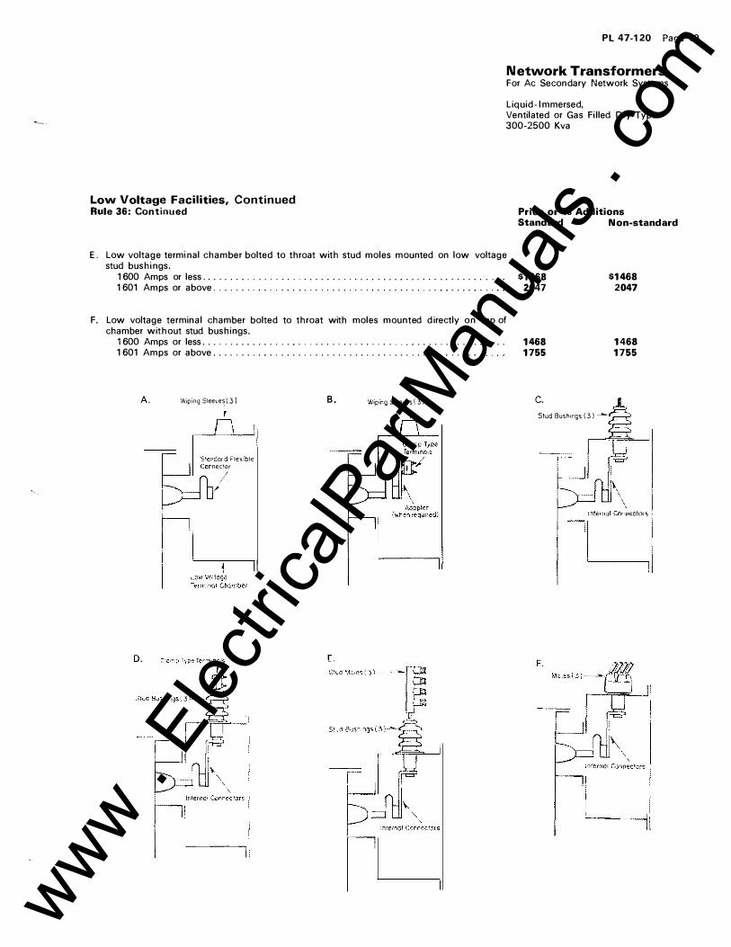
E. Low voltage terminal chamber bolted to throat with stud moles mounted on low voltage stud bushings.
1600 Amps or less .. . . ... . ...... . . . . ....... . . . . . ..... . ...... . ..... . .... . 1601 Amps or above. . . . . . . . . ... . . . . . . . ...... . . . . . . .... . . . . . . .. . . . . . . . .
F. Low voltage terminal chamber bolted to throat with moles mounted d irectly on top of chamber without stud bushings.
1600 Amps or less. . . . . . . . . . . . . . . . . . . . . . . . . . . . . . . . . . . . . . . . . .. . ... . ... . 1601 Amps or above ... . . .... . ...................... . . . . ... . . . .. . . . .
A. Wiping Sleeve� 1 3 )
rdo. r d Flex ble necwr
I I
;
I I
B. W1pmg S·eeves ( 3 J
�
$1468 2047
1468 1755
c.
Stud Bushorgs 1 3 ) �
$1468 2047
1468 1755
www . El
ectric
alPar
tMan
uals
. com
PL 47-1 20 Page 20
Network Transformers For Ac Secondary Network Systems
Liq u i d- I mmersed, Ventilated or G a s F i l led Dry- Type 300-2500 Kva
Low Voltage Facilities, Continued Rule 37: Protector Mounted at Factory (A30) Prices are based on transformers a nd protectors being shipped separately. If they are shi pped mounted together, from the factory, add mounting charge of . . . . . . . . . . . . . . . . . . . . . . . . . . . . . . . . .
Rule 38: Reactors (A32) Three- p h a se assembly (including end frames) of cable-type reactors on 21 6Y /1 25 volt network transformer. Location on outside of transformer tank.
To i ncrease reactance 1 % add . . . . . . . . . . . . .
To i ncrease reactance 2% add . . . . . . . . . . . . . To i ncrease reactance 3% add . . . . . . . . . . . . .
To increase reactance 4% add . . . . . . . . . . . . .
To i ncrease reactance 5% add . . . . . . . . . . . . .
The above prices also apply for reactors sold separately without transformers.
Conditions of Sale Rule 39: Special Warranty (in Addition to Standard Warranty in SP 47-000) (A41 ) To meet purchaser's specifications and/or terms a nd conditions that req uire the manufacturer to be l iable d u ri ng the warranty period for the d i rect cost@ of:
a. Removing a Transformer from Service b. Transportation to the Factory or Repair
Facil ity and Return to Site c . Re- installation on Site Add to the Total Net Price for Each Trans-forme r . . . . . . . . . . . . . . . . . . . . . . . . . . 2%
The Westi nghouse l iabi l ity for a., b. and c . above, u nder th is special warranty wi l l not exceed 50% of the price of the warranted apparatus. mcxnc·nsP for adjacent apparatus. fire
spare incremental supplyi ng temporary service. etc .. is not
Further Information : Description: See Descriptive B u l l et in 47-1 50 Plazatran, See PL 47- 1 21 SPOT N etwork - B alancing Coii - B - 9458
Westinghouse Electric Corporation Power Transformer D ivision, Sharon, Pa. 1 61 46 Printed in USA
Price or % Additions Standard Non-standard
$ 344
230 459 688 91 8
1 1 47
$ 344
230 459 688 918
1 1 47
Rule 40 : Extended Warranty (A42) The Westinghouse standard warranty period for power transformers covers a period of 1 2 months from the date of shipment. When purchaser's specification calls for a period over 24 months but not over 24 months from date of shipment; add to the total net price for each transformer . . . . 1%
When purchaser's specification cal ls for a period over 1 2 months but not over 36 months from date of s h ipment; add to t h e total n e t price f o r each transformer . . . . 3'Yo
It is Westinghouse policy not to extend t h e warranty period beyond 36 months from date of shipment.
Rule 41 : Accelerated or Delayed Payments (A43) The standard terms of payment are net wit h i n 30 days from d ate of invoice. There will be no reduction in price for payments more favorable to Westinghouse than the standard terms. When a purchaser's specification requires any portion of payment to be withheld beyond the standard period or if payments are not made in conformance with the standard terms, the final net price of the transformer w i l l be i ncreased by a t i me price d ifferential equal to 1 % per month or fraction thereof on the unpaid balance.
Rule 42 : Delivery (A44) F.O.B .-P/8-Frt./P pd: This apparatus i s sold f.o.b. point o f sh ipment, freight prepaid, and i ncl uded in the price. When the purchaser's specification c a l l s for f.o.b. common carrier point nearest first destination ( F.O.B.-P/D-Frt/ Ppd.) add to the total Net Price for each transformer . . . . . . . . 1 %
I n event of sh i pping loss o r d amage: 1 . Notification must be g iven to t he West
inghouse location from which the shipment originated within 72 hours of delivery;
2. Written notations of apparent l oss and d amage must be made on the carrier's del ivery receipt;
3. Concealed d amage m ust be immediately reported to the delivering carrier with a request for an i nspection.
'
l
www . El
ectric
alPar
tMan
uals
. com