what is busbar differential protection?
TRANSCRIPT

ELECTRICAL ENGINEERING ACADEMY © SAREX Communications
What is busbar differential protection?
WELCOME dear friends of protection, control & electrical engineering. In today's post we take a look at the basics of busbar differential protection. Have fun reading, a successful week and best regards,
your EEA-Team
Introduction
First of all, it can be established quite trivially that the busbar differential protection is a protection system that aims at the busbar as the relevant protected object. Since we always drive better when we understand why we are doing certain things, the following question should first be clarified:
„Why does a busbar have to be protected at all?“
August 12, 2021 Seite von 1 11

ELECTRICAL ENGINEERING ACADEMY © SAREX Communications
There are two main aspects to be mentioned here. First of all, busbars often have a very high short-circuit power. In order to keep any damage as low as possible, quick protections switch-off's are therefore required in the event of electrical short circuits in the busbar area.
Furthermore, busbars must be selectively protected in order to avoid cascade-like shutdowns and to protect other equipment that is not affected by the fault from failure. An optimally configured busbar differential protection system thus makes a significant contribution to safe and stable network operation. Due to the sometimes very complex structures of busbar systems, there are some other very specific protection requirements that go beyond the know-how of fuses and bimetallic instruments.
Challenges
A very basic requirement for busbar differential protection systems is the flexibility to adapt to the complexity of the primary system. Busbar systems can be very extensive and have many switch gears and disconnectors. These include, for example, the single busbar,
Figure 1: single busbar
August 12, 2021 Seite von 2 11

ELECTRICAL ENGINEERING ACADEMY © SAREX Communications
the double busbar
Figure 2: double busbar
or the tripple busbar:
Figure 3: triple busbar
Many other configurations such as the 1 1/2 circuit-breaker system and additional bypass bars can be found here.
Since with multiple busbars, the affected busbar must be switched off selectively while all fault-free busbars remain in operation, the complex integration and evaluation of all existing outgoing currents and disconnector positions, which is dependent on the
August 12, 2021 Seite von 3 11

ELECTRICAL ENGINEERING ACADEMY © SAREX Communications
switching status, is mandatory. Furthermore, the trip commands must also be adapted to the existing circuit and fault scenarios.
Another essential requirement is the speed of the protection system. Normative specifications on the required disconnection times for faulty busbar systems and switchgear systems lead to protection tripping times of less than 200 ms. Taking into account the high demands on availability, only modern busbar protection systems come into question here.
In addition, as with transformer differential protection and as is usual with any other protection system, over-function must be avoided. In this way, all higher-level and subordinate faults outside the protection area must not lead to the busbar differential protection system responding incorrectly. The loss of a busbar can result in major network failures and thus endanger the stability of the network. On the other hand, the availability of the protection system is of course also elementary, since disconnection that is too late or even absent, long-lasting voltage drops and thus, under unfavorable circumstances, can lead to a breakdown of the network. In the extra-high voltage, therefore, busbar protection systems that are partially fully redundant are used.
A final and very important aspect is expandability. If there are primary technical additions and expansions in later operational phases, it is desirable if the existing protection system is not limited to the initial configuration, but can be expanded accordingly and is flexible.
Protection Principle
The basic function of the differential protection is described relatively simply. The current difference criterion is one of the oldest protection criteria and is based on Kirchhoff's 1st law or the node theorem.
August 12, 2021 Seite von 4 11

ELECTRICAL ENGINEERING ACADEMY © SAREX Communications
This means that the sum of all currents flowing into a node is 0 if the signs of all currents are taken into account. Depending on the current definition, it can also be said that the sum of all currents flowing in the node must correspond to the sum of all currents flowing out of the node. The protected area is always precisely determined by the installation location of the current transformers. The busbar is therefore the "node to be monitored" and the sum of all node currents must be 0 at all times. If this criterion is violated, the current must flow off via a path that is not intended for operational purposes. So there must be an electrical fault in the protection area.
A manufacturer-dependent stabilization current is also calculated from the incoming and outgoing currents. It is clear that the devices also work with secondary values for busbar differential protection, which must be adapted and standardized accordingly. In particular, the saturation of current transformers can cause problems in the case of high currents and short circuits near busbars. While the faulty feeder carries the entire short-circuit current, the currents are divided up on the supply side and can be transmitted as cleanly as possible. If the CT of the heavily loaded feeder of the fault point saturates, the node sum deviates from the stable zero. For this reason, not only the differential current, but also the restrain-current is calculated. While the differential current is pushing towards tripping, the stabilizing current counteracts tripping.
These algorithms are designed differently by the manufacturers. For example, to calculate the differential current of a Siprotec 7SS85 from Siemens, the currents are added vectorially and then the absolut value is calculated.
August 12, 2021 Seite von 5 11
ELECTRICAL ENGINEERING ACADEMY © SAREX Communications
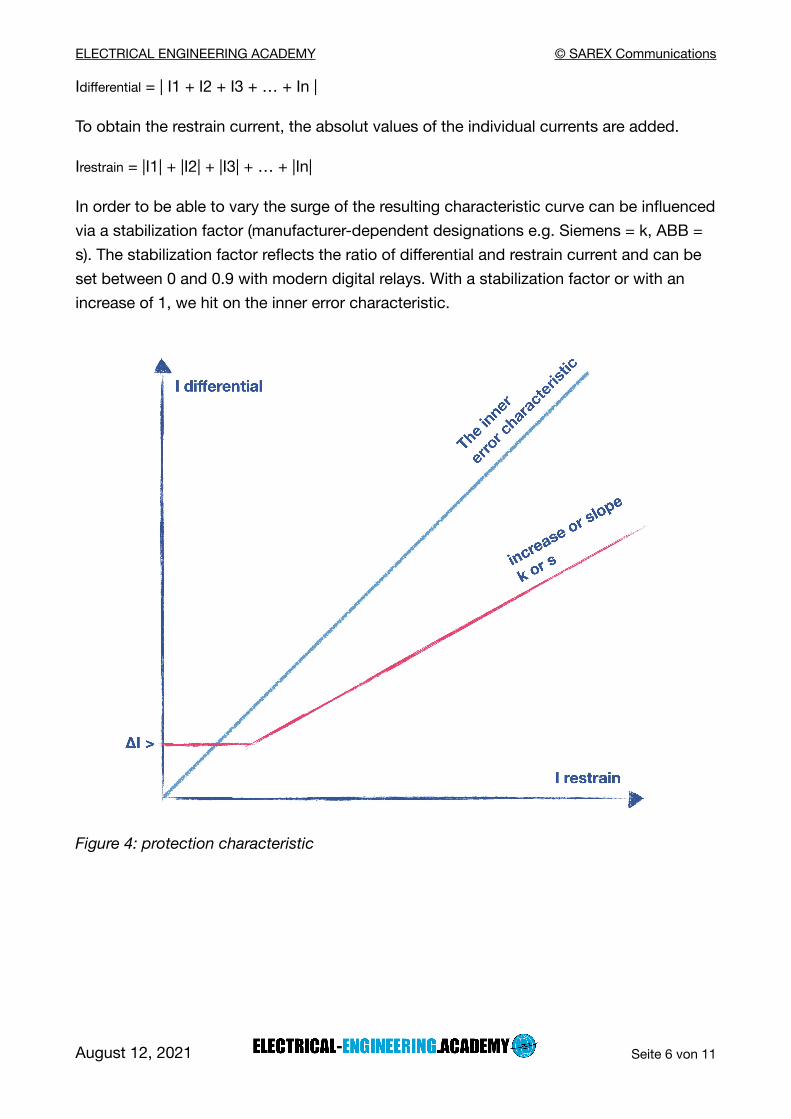
Idifferential = | I1 + I2 + I3 + … + In |
To obtain the restrain current, the absolut values of the individual currents are added.
Irestrain = |I1| + |I2| + |I3| + … + |In|
In order to be able to vary the surge of the resulting characteristic curve can be influenced via a stabilization factor (manufacturer-dependent designations e.g. Siemens = k, ABB = s). The stabilization factor reflects the ratio of differential and restrain current and can be set between 0 and 0.9 with modern digital relays. With a stabilization factor or with an increase of 1, we hit on the inner error characteristic.
Figure 4: protection characteristic
August 12, 2021 Seite von 6 11

ELECTRICAL ENGINEERING ACADEMY © SAREX Communications
Structure
We have to differentiate the basic structure between centralized and decentralized busbar differential protection systems. The decisive factor here is the location at which the AD conversion of the primary currents takes place.
With the central approach, the A / D conversion takes place directly in the central part. This means that all currents and disconnectors are transferred directly from the bays to the central unit. This structure is used in smaller primary systems.
Figure 5: central busbar differential protection
Decentralized systems are used for larger switch-gears. These record and convert the currents in the bays conductor-selective. The currents recorded and digitized by field units, which are also used for other control and protection functions, are then transferred to a central unit via fiber optic cables.
August 12, 2021 Seite von 7 11

ELECTRICAL ENGINEERING ACADEMY © SAREX Communications
Figure 6: decentralized busbar differential protection
Zone
First of all, the basic idea that the busbar differential protection always refers to individual busbars and also to individual busbar sections is important here. The aim is to achieve selective protection reactions for maximum availability. As already described, it is the current transformer installation locations in the outgoing feeders and coupling fields that define the individual protection areas. It is therefore a specific feature for busbar differential protection to set up zones or busbar sections. Particularly with larger multiple busbar systems, it is necessary to define separate protection areas based on the switching status and to provide them with independent, phase-selective and fully functional differential protection algorithms. In addition, the hardware-redundant separation of zones was and is common as well.
Mapping
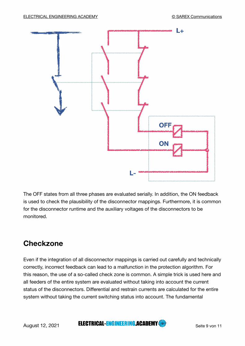
The mappings of the current disconnector states are used to record and assign the relevant feeder currents, since only the feeders that are in operation should enter the protection zone.
August 12, 2021 Seite von 8 11
ELECTRICAL ENGINEERING ACADEMY © SAREX Communications
The OFF states from all three phases are evaluated serially. In addition, the ON feedback is used to check the plausibility of the disconnector mappings. Furthermore, it is common for the disconnector runtime and the auxiliary voltages of the disconnectors to be monitored.
Checkzone
Even if the integration of all disconnector mappings is carried out carefully and technically correctly, incorrect feedback can lead to a malfunction in the protection algorithm. For this reason, the use of a so-called check zone is common. A simple trick is used here and all feeders of the entire system are evaluated without taking into account the current status of the disconnectors. Differential and restrain currents are calculated for the entire system without taking the current switching status into account. The fundamental
August 12, 2021 Seite von 9 11

ELECTRICAL ENGINEERING ACADEMY © SAREX Communications
problem arises that when calculating the restrain current in case of multiple busbars, a value that is too high is calculated. The figure below illustrates the problem.
Figure 8: Checkzone
The differential current results from:
Idifferential = | I1 + I2 + I3 + I4 + I5 - I4 - I5 | = | I1 + I2 + I3 |
When calculating the restrain current, there is now an undesirable over-stabilization, as the load currents I4 and I5 are included in the calculation twice:
Irestrain = |I1| + |I2| + |I3| + |I4| + |I5| + |I4| + |I5|
To counter this problem, the stabilization current for the check zone is calculated as an alternative. First, the sum of the absolut values of all currents flowing in the direction of the busbar is formed. The small p stands for "positive direction":
∑ | Ip |
In addition, the sum of the absolut values of all currents flowing off the busbar is determined. The small n stands for "negative direction":
∑ | In |
The smaller total current amount determined is now used as restrain current Irestrain:
Irestrain = the lesser of ∑ | Ip | and ∑ | In |
For our example just shown, this means:
∑ | Ip | = |I1| + |I2| + |I3| + |I4| + |I5|
August 12, 2021 Seite von 10 11

ELECTRICAL ENGINEERING ACADEMY © SAREX Communications
∑ | In | = |I4| + |I5|
Irestrain = ∑ | In | = |I4| + |I5|
Summary
Busbar differential protection systems are used for fast and selective protection of busbars and can be implemented both centrally and decentralized. The basic mode of operation is based on the classic differential protection, in which all input and output currents are monitored and used to evaluate the operating or fault status. Manufacturer-specific stabilization and optimization measures contribute to safe operation and protection against overfunction.
There are many other important technical aspects relating to busbar differential protection, such as phase comparison, breaker failure protection or, for example, the topic of auxiliary voltage loss. For a more in-depth look at the topic, we recommend the Siemens publication by Gerhard Ziegler.
Kind Regards
Your EEA-Team
August 12, 2021 Seite von 11 11