wood group manual rp1164
TRANSCRIPT

RP-1164RP-1164RP-1164RP-1164RP-1164Page 28
Repsol ExplorationRepsol ExplorationRepsol ExplorationRepsol ExplorationRepsol Exploration18-5/8" x 13-3/8" x 9-5/8" x 4-1/2" 5M18-5/8" x 13-3/8" x 9-5/8" x 4-1/2" 5M18-5/8" x 13-3/8" x 9-5/8" x 4-1/2" 5M18-5/8" x 13-3/8" x 9-5/8" x 4-1/2" 5M18-5/8" x 13-3/8" x 9-5/8" x 4-1/2" 5M
Conventional Wellhead AssemblyConventional Wellhead AssemblyConventional Wellhead AssemblyConventional Wellhead AssemblyConventional Wellhead Assembly
Wood GroupPressure Control
Wellhead EquipmentRunning Proceduresfor:
Repsol ExplorationRepsol ExplorationRepsol ExplorationRepsol ExplorationRepsol Exploration18-5/8" x 13-3/8" x 9-5/8" x 4-1/2" 5M18-5/8" x 13-3/8" x 9-5/8" x 4-1/2" 5M18-5/8" x 13-3/8" x 9-5/8" x 4-1/2" 5M18-5/8" x 13-3/8" x 9-5/8" x 4-1/2" 5M18-5/8" x 13-3/8" x 9-5/8" x 4-1/2" 5MConConConConConvvvvventional entional entional entional entional WWWWWellhead ellhead ellhead ellhead ellhead AssembAssembAssembAssembAssemblylylylyly
Publication # RP-1164September 26, 2007
Wood Group Pressure Control

RP-1164RP-1164RP-1164RP-1164RP-1164Page 27
Repsol ExplorationRepsol ExplorationRepsol ExplorationRepsol ExplorationRepsol Exploration18-5/8" x 13-3/8" x 9-5/8" x 4-1/2" 5M18-5/8" x 13-3/8" x 9-5/8" x 4-1/2" 5M18-5/8" x 13-3/8" x 9-5/8" x 4-1/2" 5M18-5/8" x 13-3/8" x 9-5/8" x 4-1/2" 5M18-5/8" x 13-3/8" x 9-5/8" x 4-1/2" 5M
Conventional Wellhead AssemblyConventional Wellhead AssemblyConventional Wellhead AssemblyConventional Wellhead AssemblyConventional Wellhead Assembly
Wood GroupPressure Control
TTTTTababababable of Contentsle of Contentsle of Contentsle of Contentsle of Contents
Bill of MaterialsBill of MaterialsBill of MaterialsBill of MaterialsBill of Materials ..................................................................................................................................................................................................................................................................................................11111
Stage 1 —Stage 1 —Stage 1 —Stage 1 —Stage 1 — Install the Casing Head AssemblyInstall the Casing Head AssemblyInstall the Casing Head AssemblyInstall the Casing Head AssemblyInstall the Casing Head Assembly ..........................................................................................................................................................................44444
Stage 2 —Stage 2 —Stage 2 —Stage 2 —Stage 2 — Test BOP StackTest BOP StackTest BOP StackTest BOP StackTest BOP Stack ..................................................................................................................................................................................................................................................................................................66666
Stage 3 —Stage 3 —Stage 3 —Stage 3 —Stage 3 — Run the 13-5/8" Wear BushingRun the 13-5/8" Wear BushingRun the 13-5/8" Wear BushingRun the 13-5/8" Wear BushingRun the 13-5/8" Wear Bushing ...................................................................................................................................................................................................77777Run the Wear Bushing Before Drilling ............................................................ 7Retrieve the Wear Bushing After Drilling ......................................................... 7
Stage 4 —Stage 4 —Stage 4 —Stage 4 —Stage 4 — Hang Off the 13-3/8" CasingHang Off the 13-3/8" CasingHang Off the 13-3/8" CasingHang Off the 13-3/8" CasingHang Off the 13-3/8" Casing ..................................................................................................................................................................................................................88888
Stage 5 —Stage 5 —Stage 5 —Stage 5 —Stage 5 — Install the Casing SpoolInstall the Casing SpoolInstall the Casing SpoolInstall the Casing SpoolInstall the Casing Spool ...................................................................................................................................................................................................................................... 1010101010Flange Test ...................................................................................................... 11
Stage 6 —Stage 6 —Stage 6 —Stage 6 —Stage 6 — Test the BOP StackTest the BOP StackTest the BOP StackTest the BOP StackTest the BOP Stack ............................................................................................................................................................................................................................................................... 1212121212
Stage 7 —Stage 7 —Stage 7 —Stage 7 —Stage 7 — Run the Wear BushingRun the Wear BushingRun the Wear BushingRun the Wear BushingRun the Wear Bushing ........................................................................................................................................................................................................................................... 1313131313Run the Wear Bushing Before Drilling .......................................................... 13Retrieve the Wear Bushing After Drilling ....................................................... 13
Stage 8 —Stage 8 —Stage 8 —Stage 8 —Stage 8 — Hang Off the 9-5/8" CasingHang Off the 9-5/8" CasingHang Off the 9-5/8" CasingHang Off the 9-5/8" CasingHang Off the 9-5/8" Casing ............................................................................................................................................................................................................. 1414141414
Stage 9 —Stage 9 —Stage 9 —Stage 9 —Stage 9 — Install the Tubing HeadInstall the Tubing HeadInstall the Tubing HeadInstall the Tubing HeadInstall the Tubing Head ...................................................................................................................................................................................................................................... 1616161616Energize the P Seals ........................................................................................ 17Test Between the Seals .................................................................................... 17Flange Test ...................................................................................................... 18
Stage 10 —Stage 10 —Stage 10 —Stage 10 —Stage 10 — Testing the BOP StackTesting the BOP StackTesting the BOP StackTesting the BOP StackTesting the BOP Stack ........................................................................................................................................................................................................................................... 1919191919
Stage 11 —Stage 11 —Stage 11 —Stage 11 —Stage 11 — Run the Wear BushingRun the Wear BushingRun the Wear BushingRun the Wear BushingRun the Wear Bushing ........................................................................................................................................................................................................................................... 2020202020Run the Wear Bushing Before Drilling .......................................................... 20Retrieve the Wear Bushing After Drilling ....................................................... 20
Stage 12 —Stage 12 —Stage 12 —Stage 12 —Stage 12 — Hang Off the 4-1/2" TubingHang Off the 4-1/2" TubingHang Off the 4-1/2" TubingHang Off the 4-1/2" TubingHang Off the 4-1/2" Tubing ............................................................................................................................................................................................................. 2121212121Landing the Tubing Hanger ........................................................................... 22
Stage 13 —Stage 13 —Stage 13 —Stage 13 —Stage 13 — Install Production TreeInstall Production TreeInstall Production TreeInstall Production TreeInstall Production Tree ...................................................................................................................................................................................................................................... 2323232323Flange Test ...................................................................................................... 24
Integral Lockscrew OperationIntegral Lockscrew OperationIntegral Lockscrew OperationIntegral Lockscrew OperationIntegral Lockscrew Operation ......................................................................................................................................................................................... 2525252525Lockscrew Operation Instructions .................................................................. 25
Recommended Procedure for Field Welding Pipe toRecommended Procedure for Field Welding Pipe toRecommended Procedure for Field Welding Pipe toRecommended Procedure for Field Welding Pipe toRecommended Procedure for Field Welding Pipe to
Wellhead Parts for Pressure SealWellhead Parts for Pressure SealWellhead Parts for Pressure SealWellhead Parts for Pressure SealWellhead Parts for Pressure Seal ..................................................................................................................................................................... 2626262626

RP-1164RP-1164RP-1164RP-1164RP-1164Page 1
Repsol ExplorationRepsol ExplorationRepsol ExplorationRepsol ExplorationRepsol Exploration18-5/8" x 13-3/8" x 9-5/8" x 4-1/2" 5M18-5/8" x 13-3/8" x 9-5/8" x 4-1/2" 5M18-5/8" x 13-3/8" x 9-5/8" x 4-1/2" 5M18-5/8" x 13-3/8" x 9-5/8" x 4-1/2" 5M18-5/8" x 13-3/8" x 9-5/8" x 4-1/2" 5M
Conventional Wellhead AssemblyConventional Wellhead AssemblyConventional Wellhead AssemblyConventional Wellhead AssemblyConventional Wellhead Assembly
Wood GroupPressure Control
Bill of MaterialsBill of MaterialsBill of MaterialsBill of MaterialsBill of Materials

RP-1164RP-1164RP-1164RP-1164RP-1164Page 2
Repsol ExplorationRepsol ExplorationRepsol ExplorationRepsol ExplorationRepsol Exploration18-5/8" x 13-3/8" x 9-5/8" x 4-1/2" 5M18-5/8" x 13-3/8" x 9-5/8" x 4-1/2" 5M18-5/8" x 13-3/8" x 9-5/8" x 4-1/2" 5M18-5/8" x 13-3/8" x 9-5/8" x 4-1/2" 5M18-5/8" x 13-3/8" x 9-5/8" x 4-1/2" 5M
Conventional Wellhead AssemblyConventional Wellhead AssemblyConventional Wellhead AssemblyConventional Wellhead AssemblyConventional Wellhead Assembly
Wood GroupPressure Control
CASING HEAD ASSEMBLYCASING HEAD ASSEMBLYCASING HEAD ASSEMBLYCASING HEAD ASSEMBLYCASING HEAD ASSEMBLY
ItemItemItemItemItemQtyQtyQtyQtyQty DescriptionDescriptionDescriptionDescriptionDescription
A1 1 Casing Head, WG, W2, 20-3/4" 3Mx 18-5/8" SOW, with two 2" line pipeoutlets with o-ring, 6A-PU-AA-2-2Part # 363832
A2 1 Baseplate Assembly, WG, SplitWeldless, 36" O.D. x 21.6" I.D. topx 13.0" tall, 2000 KIP capacityPart # 363966
A3 1 Gate Valve, model 1000, 2-1/16"3/5M, 2" line pipe, handwheel oper-ated, AA trim, 6A-PU-AA -2-2Part # 354016
A4 1 Nipple, 2" line pipe x 6" long, sched-ule 160, ANSI 4130Part # NI6-API
A5 1 Bull Plug, 2" line pipe x blank, 4" long,API 6APart # BPS-API
A6 1 Bull Plug, 2" line pipe, tapped 1/2"NPT, 4" long, API 6APart # BPT-API
A7 1 Needle Valve, 1/2" NPT male x fe-male, anglePart # NVA
A8 1 Pressure Gauge, 0-5000 psi, 4-1/2"O.D. face, 1/2" NPT male,Part # PG5
A9 1 Ring Gasket, RX-74, carbon steelplated, API 6A, PSL1-4Part # RX74
A10 20 Studs, with two nuts each, plated, 2"8UNC x 14.75" long, stud A193-GRB7, nut A194-GR 2HPart # 327099
A11 1 Casing Hanger, WG, W2, 20" x 13-3/8", 6A-L-AA-4-2Part # 342495
Bill of MaBill of MaBill of MaBill of MaBill of Materterterterterialsialsialsialsials
CASING SPOOL ASSEMBLYCASING SPOOL ASSEMBLYCASING SPOOL ASSEMBLYCASING SPOOL ASSEMBLYCASING SPOOL ASSEMBLY
ItemItemItemItemItemQtyQtyQtyQtyQty DescriptionDescriptionDescriptionDescriptionDescription
B1 1 Casing Spool, WG, W2-SGLEBS,20-3/4" 3M x 13-5/8" 5M, with two 2-1/16" 5M studded outlets, 6A-PU-EE-NL-2-2Part # 363834
B2 1 Gate Valve, model 2200T, 2-1/16" 3/5M, flanged end, handwheel oper-ated, EE-0,5 trim, 6A-LU-EE-0,5-2-2Part # 349273
B3 2 Companion Flange, 2-1/16" 5M x 2"line pipe, 6A-U-EE-NL-2Part # 323350
B4 1 Bull Plug, 2" line pipe x blank, 4" long,API 6APart # BPS-API
B5 1 Bull Plug, 2" line pipe, tapped 1/2"NPT, 4" long, API 6APart # BPT-API
B6 3 Ring Gasket, RX-24, carbon steel,carbon steel plated, API 6A, PSL1-4Part # RX24
B7 8 Studs, with two nuts each, plated, 7/8"9UNC x 6.50" long, stud A193-GRB7, nut A194-GR 2HPart # 800972
B8 1 Needle Valve, 1/2" NPT male x fe-male, anglePart # NVA
B9 1 Pressure Gauge, 0-5000 psi, 4-1/2"O.D. face, 1/2" NPT male,Part # PG5
B10 1 Ring Gasket, BX-160, carbon steel,carbon steel plated, API 6A, PSL1-4Part # BX160
B11 16 Studs, with two nuts each, plated, 1-5/8" 8UNC x 12.75" long, stud A193-GR B7, nut A194-GR 2HPart # 801737
B12 Casing Hanger, WG, W2, 13-5/8" x9-5/8", 6A-L-AA-4-2Part # 341640
TUBING HEAD ASSEMBLYTUBING HEAD ASSEMBLYTUBING HEAD ASSEMBLYTUBING HEAD ASSEMBLYTUBING HEAD ASSEMBLY
ItemItemItemItemItemQtyQtyQtyQtyQty DescriptionDescriptionDescriptionDescriptionDescription
C1 1 Tubing Head, WG, T-DBLEBS,13-5/8" 5M x 11" 5M, with two 2-1/16" 5M studded outlets, 6A-PU-EE-NL-2-2Part # 340991
C2 2 Gate Valve, model 2200T, 2-1/16" 3/5M, flanged end, handwheel oper-ated, EE-0,5 trim, 6A-LU-EE-0,5-2-2Part # 349273
C3 2 Companion Flange, 2-1/16" 5M x 2"line pipe, 6A-U-EE-NL-2Part # 323350
C4 1 Bull Plug, 2" line pipe x blank, 4" long,API 6APart # BPS-API
C5 1 Bull Plug, 2" line pipe, tapped 1/2"NPT, 4" long, API 6APart # BPT-API
C6 4 Ring Gasket, RX-24, carbon steel,carbon steel plated, API 6A, PSL1-4Part # RX24
C7 16 Studs, with two nuts each, plated, 7/8" 9UNC x 6.50" long, stud A193-GR B7, nut A194-GR 2HPart # 800972
C8 1 Needle Valve, 1/2" NPT male x fe-male, anglePart # NVA
C9 1 Pressure Gauge, 0-5000 psi, 4-1/2"O.D. face, 1/2" NPT male,Part # PG5
C10 Tubing Hanger, WG, T-M56, 11" x4-1/2" (12.6#) New Vam bottom andtop, with 4" H BPV thread, 6A-U-AA-2-2Part # 398801

RP-1164RP-1164RP-1164RP-1164RP-1164Page 3
Repsol ExplorationRepsol ExplorationRepsol ExplorationRepsol ExplorationRepsol Exploration18-5/8" x 13-3/8" x 9-5/8" x 4-1/2" 5M18-5/8" x 13-3/8" x 9-5/8" x 4-1/2" 5M18-5/8" x 13-3/8" x 9-5/8" x 4-1/2" 5M18-5/8" x 13-3/8" x 9-5/8" x 4-1/2" 5M18-5/8" x 13-3/8" x 9-5/8" x 4-1/2" 5M
Conventional Wellhead AssemblyConventional Wellhead AssemblyConventional Wellhead AssemblyConventional Wellhead AssemblyConventional Wellhead Assembly
Wood GroupPressure Control
RECOMMENDED SERVICE TOOLSRECOMMENDED SERVICE TOOLSRECOMMENDED SERVICE TOOLSRECOMMENDED SERVICE TOOLSRECOMMENDED SERVICE TOOLS
ItemItemItemItemItemQtyQtyQtyQtyQty DescriptionDescriptionDescriptionDescriptionDescription
ST1 1 Test Plug/Retrieving Tool, SL, 20"nominal x 4-1/2" IF box x boxPart # 336842
ST2 1 Wear Bushing, SL, 20" nominal x17.62" ID x 11.8" longPart # 337442
ST3 1 Test Plug/Running and RetrievingTool, SL, 13-5/8" nominal x 4-1/2" IFbox top and bottomPart # 332044
ST4 1 Wear Bushing, SL, 13-5/8" nominal x12-1/4" bitPart # 354660
ST5 1 Test Plug/Running and RetrievingTool, SL, 11" nominal x 4-1/2" IF boxtop and bottomPart # 334030
ST6 1 Wear Bushing, SL, 11" nominal x 8-7/8" bitPart # 348213
ST7 1 Protector Cap, M56Part # 313941
ST8 1 4" One-Way Type H Back PressdureValvePart # 350314

RP-1164RP-1164RP-1164RP-1164RP-1164Page 4
Repsol ExplorationRepsol ExplorationRepsol ExplorationRepsol ExplorationRepsol Exploration18-5/8" x 13-3/8" x 9-5/8" x 4-1/2" 5M18-5/8" x 13-3/8" x 9-5/8" x 4-1/2" 5M18-5/8" x 13-3/8" x 9-5/8" x 4-1/2" 5M18-5/8" x 13-3/8" x 9-5/8" x 4-1/2" 5M18-5/8" x 13-3/8" x 9-5/8" x 4-1/2" 5M
Conventional Wellhead AssemblyConventional Wellhead AssemblyConventional Wellhead AssemblyConventional Wellhead AssemblyConventional Wellhead Assembly
Wood GroupPressure Control
Stage 1 —Stage 1 —Stage 1 —Stage 1 —Stage 1 — Install the Casing Head Install the Casing Head Install the Casing Head Install the Casing Head Install the Casing Head AssembAssembAssembAssembAssemblylylylyly
1. Run the conductor and 18-5/8" surface casing tothe required depth and cement in place. Allowcement to set.
2. Cut the conductor pipe off at the desired elevationabove the cellar floor.
Note: Ensure the cut on the conductor is smooth andlevel.
3. Cut the 18-5/8" casing at 16.50" above the conduc-tor pipe stub and remove spent casing.
4. Grind the 18-5/8" casing stub level and place asmall bevel on the O.D. of the stub.
5. Examine the 20-3/4" 3M x 18-5/8" SOW W2Casing Head Assembly (Item A1). Verify thefollowing:• seal areas, bore, ports, exposed ring groove
are clean and undamaged• fittings, studs and nuts, and valves are intact
and undamaged• ensure that the test o-ring is in place and in
good condition
6. Thoroughly clean the SOW pocket of the headremoving all old grease and debris
7. Align and level the Casing Head over the casingstub, orienting the outlets so they will be compat-ible with the drilling equipment.
8. Remove the pipe plug from the port on the bottomof the head.
9. Slowly and carefully lower the assembly over thecasing stub and weld the Assembly to the 18-5/8"surface casing outside.
10. Test the weld as instructed and replace the pipeplug in the port on the bottom of the Head.
Note: The weld should be a fillet-type weld with legs noless than the wall thickness of the casing. Legs of 1/2" to5/8" are adequate for most jobs.
Refer to the back of this publication for the Recom-mended Procedure for Field Welding Pipe toWellhead Parts for Pressure Seal and for fieldtesting of the weld connection. The following chartindicates acceptable and unacceptable test media.
aideMtseT
saideMelbatpeccA saideMelbatpeccanU
retaWliOelbauloSretaW
saGtrenInegortiN
saGnogrA
negyxOenelytecA
liOciluardyHliOrotoM
diulFkcarB

RP-1164RP-1164RP-1164RP-1164RP-1164Page 5
Repsol ExplorationRepsol ExplorationRepsol ExplorationRepsol ExplorationRepsol Exploration18-5/8" x 13-3/8" x 9-5/8" x 4-1/2" 5M18-5/8" x 13-3/8" x 9-5/8" x 4-1/2" 5M18-5/8" x 13-3/8" x 9-5/8" x 4-1/2" 5M18-5/8" x 13-3/8" x 9-5/8" x 4-1/2" 5M18-5/8" x 13-3/8" x 9-5/8" x 4-1/2" 5M
Conventional Wellhead AssemblyConventional Wellhead AssemblyConventional Wellhead AssemblyConventional Wellhead AssemblyConventional Wellhead Assembly
Wood GroupPressure Control
11. Attach a suitable lifting devise to thetop of the casing head and pull up on thehead.
12. Locate the 32" O.D. Split Weldless32" O.D. Split Weldless32" O.D. Split Weldless32" O.D. Split Weldless32" O.D. Split WeldlessBase Plate (Item A2)Base Plate (Item A2)Base Plate (Item A2)Base Plate (Item A2)Base Plate (Item A2). Verify that:• assembly is clean and in good con-
dition• all bolting is present
13. Remove the eight 1" studs and nutsfrom the baseplate gussets and sepa-rate the base plate in two halves.
14. Using the blocks, lift up on the casinghead to ensure a gap of 13.00" existbetween the conductor pipe stub andthe bottom of the casing head.
15. Using the air hoist, carefully lower onehalf of the base plate into the cellar andplace it on top of the conductor pipeand around the 18-5/8" surface casing.
16. Carefully lower the second half into thecellar and mate it to the first half andthen set it down on the conductor.
17. Ensure all the bolt holes in the gussetsaline and then install the eight 1" studsand nuts and tighten nuts securely.
18. Ensure the bolted gussets come face toface and then torque all nuts to ap-proximately 200 ft-lbs.
19. Slack off all weight on the blocks andallow the casing head to rest on top ofthe base plate.
Stage 1 —Stage 1 —Stage 1 —Stage 1 —Stage 1 — Install the Casing Head Install the Casing Head Install the Casing Head Install the Casing Head Install the Casing Head AssembAssembAssembAssembAssemblylylylyly

RP-1164RP-1164RP-1164RP-1164RP-1164Page 6
Repsol ExplorationRepsol ExplorationRepsol ExplorationRepsol ExplorationRepsol Exploration18-5/8" x 13-3/8" x 9-5/8" x 4-1/2" 5M18-5/8" x 13-3/8" x 9-5/8" x 4-1/2" 5M18-5/8" x 13-3/8" x 9-5/8" x 4-1/2" 5M18-5/8" x 13-3/8" x 9-5/8" x 4-1/2" 5M18-5/8" x 13-3/8" x 9-5/8" x 4-1/2" 5M
Conventional Wellhead AssemblyConventional Wellhead AssemblyConventional Wellhead AssemblyConventional Wellhead AssemblyConventional Wellhead Assembly
Wood GroupPressure Control
Stage 2 —Stage 2 —Stage 2 —Stage 2 —Stage 2 — TTTTTest BOP Stackest BOP Stackest BOP Stackest BOP Stackest BOP Stack
1. Examine the 20" SL Test Plug/Re-20" SL Test Plug/Re-20" SL Test Plug/Re-20" SL Test Plug/Re-20" SL Test Plug/Re-trieving Tool (Item ST1)trieving Tool (Item ST1)trieving Tool (Item ST1)trieving Tool (Item ST1)trieving Tool (Item ST1)..... Verify thefollowing:• elastomer seals, lift lugs, and plugs
are intact and in good condition• drill pipe threads are clean and in
good condition
2. Install a new Ring Gasket in the ringgroove of the Casing Head and makeup the BOP stack.
Immediately after making up the BOP stackand periodically during the drilling of thehole for the next casing string, the BOP stack(connections and rams) must be tested.
3. Orient the Tool with elastomer downand lift lugs up. Make up a joint of drillpipe to the Tool.
WARNINGWARNINGWARNINGWARNINGWARNING::::: Make sure the elastomer iselastomer iselastomer iselastomer iselastomer isdowndowndowndowndown and the lift lugs are uplift lugs are uplift lugs are uplift lugs are uplift lugs are up.
4. Remove 1/2" NPT pipe plug if pres-sure is to be supplied through the drillpipe.
5. Lubricate the elastomer seal of the Toolwith a light oil or grease.
6. Lower the Tool through the BOP andinto the Casing Head until it lands onthe load shoulder in the Casing Head,8.52" below the top of the head.
7. Close the BOP rams on the drill pipeand test to 3,000 psi. or as required bydrilling supervisor.
8. After a satisfactory test, release pres-sure, and open the rams.
9. Remove as much fluid from the BOPstack as possible.
10. Retrieve the Tool slowly to avoid dam-age to the seal.
11. Repeat this procedure as required dur-ing the drilling of the hole.

RP-1164RP-1164RP-1164RP-1164RP-1164Page 7
Repsol ExplorationRepsol ExplorationRepsol ExplorationRepsol ExplorationRepsol Exploration18-5/8" x 13-3/8" x 9-5/8" x 4-1/2" 5M18-5/8" x 13-3/8" x 9-5/8" x 4-1/2" 5M18-5/8" x 13-3/8" x 9-5/8" x 4-1/2" 5M18-5/8" x 13-3/8" x 9-5/8" x 4-1/2" 5M18-5/8" x 13-3/8" x 9-5/8" x 4-1/2" 5M
Conventional Wellhead AssemblyConventional Wellhead AssemblyConventional Wellhead AssemblyConventional Wellhead AssemblyConventional Wellhead Assembly
Wood GroupPressure Control
Stage 3 —Stage 3 —Stage 3 —Stage 3 —Stage 3 — Run the 13-5/8" Run the 13-5/8" Run the 13-5/8" Run the 13-5/8" Run the 13-5/8" WWWWWear Bushingear Bushingear Bushingear Bushingear Bushing
Note: AlwaysNote: AlwaysNote: AlwaysNote: AlwaysNote: Always use a Wear Bushing whiledrilling to protect the load shoulders fromdamage by the drill bit or rotating drill pipe.The Wear Bushing must be retrievedmust be retrievedmust be retrievedmust be retrievedmust be retrieved priorto running the casing.
1. Examine the 20" Nominal SL Wear20" Nominal SL Wear20" Nominal SL Wear20" Nominal SL Wear20" Nominal SL WearBushing (Item ST2)Bushing (Item ST2)Bushing (Item ST2)Bushing (Item ST2)Bushing (Item ST2)..... Verify the inter-nal bore is clean and in good condition.
Run the Wear Bushing BeforeRun the Wear Bushing BeforeRun the Wear Bushing BeforeRun the Wear Bushing BeforeRun the Wear Bushing BeforeDrillingDrillingDrillingDrillingDrilling
2. Orient the 20" SL Test Plug/Retriev-20" SL Test Plug/Retriev-20" SL Test Plug/Retriev-20" SL Test Plug/Retriev-20" SL Test Plug/Retriev-ing Tool (Item ST1)ing Tool (Item ST1)ing Tool (Item ST1)ing Tool (Item ST1)ing Tool (Item ST1) with the lift lugsdown and the elastomer up.
WARNINGWARNINGWARNINGWARNINGWARNING::::: Make sure the lift lugs are downlift lugs are downlift lugs are downlift lugs are downlift lugs are downand the elastomer is upelastomer is upelastomer is upelastomer is upelastomer is up when latching intothe Wear Bushing.
3. Attach the Tool to a joint of drill pipe.
4. Align the retractable lift lugs of the toolwith the retrieval holes of the bushing andthe carefully lower the Tool into the WearBushing until the lugs snap into place.
Note: If the lugs did not align with the holes,rotate the tool in either direction until theysnap into place.
5. Apply a heavy coat of grease, not dope, tothe OD of the bushing.
6. Slowly lower the Tool/Bushing Assem-bly through the BOP stack and land it onthe load shoulder of the casing head, 8.52"below the top of the head.
7. Remove the Tool from the Wear Bushingby rotating the drill pipe counter clock-wise 1/4 turn and lifting straight up.
8. Drill as required.
Note: It is highly recommended to retrieve,clean, inspect, grease, and reset the wear bush-ing each time the hole is tripped during thedrilling of the hole section.
Retrieve the Wear Bushing After DrillingRetrieve the Wear Bushing After DrillingRetrieve the Wear Bushing After DrillingRetrieve the Wear Bushing After DrillingRetrieve the Wear Bushing After Drilling
9. Make up the Tool to the drill pipe with the lift lugs down and the elastomer up.
10. Slowly lower the Tool into the Wear Bushing.
11. Pick up and balance the riser weight.
12. Rotate the Tool clockwise until a positive stop is felt. This indicates the lugs havesnapped into the holes in the bushing.
13. Retrieve the Wear Bushing using the elevators if possible, and remove it and the Toolfrom the drill string.
RP-1164RP-1164RP-1164RP-1164RP-1164Page 8
Repsol ExplorationRepsol ExplorationRepsol ExplorationRepsol ExplorationRepsol Exploration18-5/8" x 13-3/8" x 9-5/8" x 4-1/2" 5M18-5/8" x 13-3/8" x 9-5/8" x 4-1/2" 5M18-5/8" x 13-3/8" x 9-5/8" x 4-1/2" 5M18-5/8" x 13-3/8" x 9-5/8" x 4-1/2" 5M18-5/8" x 13-3/8" x 9-5/8" x 4-1/2" 5M
Conventional Wellhead AssemblyConventional Wellhead AssemblyConventional Wellhead AssemblyConventional Wellhead AssemblyConventional Wellhead Assembly
Wood GroupPressure Control
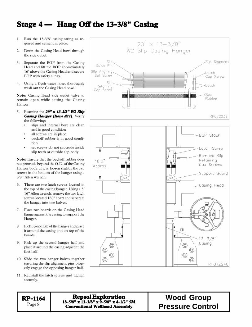
Stage 4 —Stage 4 —Stage 4 —Stage 4 —Stage 4 — Hang Off the 13-3/8" CasingHang Off the 13-3/8" CasingHang Off the 13-3/8" CasingHang Off the 13-3/8" CasingHang Off the 13-3/8" Casing
1. Run the 13-3/8" casing string as re-quired and cement in place.
2. Drain the Casing Head bowl throughthe side outlet.
3. Separate the BOP from the CasingHead and lift the BOP approximately16" above the Casing Head and secureBOP with safety slings.
4. Using a fresh water hose, thoroughlywash out the Casing Head bowl.
Note: Casing Head side outlet valve toremain open while setting the CasingHanger.
5. Examine the 20" x 13-3/8" W2 Slip20" x 13-3/8" W2 Slip20" x 13-3/8" W2 Slip20" x 13-3/8" W2 Slip20" x 13-3/8" W2 SlipCasing Hanger (Item A11)Casing Hanger (Item A11)Casing Hanger (Item A11)Casing Hanger (Item A11)Casing Hanger (Item A11)..... Verifythe following:• slips and internal bore are clean
and in good condition• all screws are in place• packoff rubber is in good condi-
tion• set screws do not protrude inside
slip teeth or outside slip body
Note: Ensure that the packoff rubber doesnot protrude beyond the O.D. of the CasingHanger body. If it is, loosen slightly the capscrews in the bottom of the hanger using a3/8” Allen wrench.
6. There are two latch screws located inthe top of the casing hanger. Using a 5/16” Allen wrench, remove the two latchscrews located 180° apart and separatethe hanger into two halves.
7. Place two boards on the Casing Headflange against the casing to support theHanger.
8. Pick up one half of the hanger and placeit around the casing and on top of theboards.
9. Pick up the second hanger half andplace it around the casing adjacent thefirst half.
10. Slide the two hanger halves togetherensuring the slip alignment pins prop-erly engage the opposing hanger half.
11. Reinstall the latch screws and tightensecurely.

RP-1164RP-1164RP-1164RP-1164RP-1164Page 9
Repsol ExplorationRepsol ExplorationRepsol ExplorationRepsol ExplorationRepsol Exploration18-5/8" x 13-3/8" x 9-5/8" x 4-1/2" 5M18-5/8" x 13-3/8" x 9-5/8" x 4-1/2" 5M18-5/8" x 13-3/8" x 9-5/8" x 4-1/2" 5M18-5/8" x 13-3/8" x 9-5/8" x 4-1/2" 5M18-5/8" x 13-3/8" x 9-5/8" x 4-1/2" 5M
Conventional Wellhead AssemblyConventional Wellhead AssemblyConventional Wellhead AssemblyConventional Wellhead AssemblyConventional Wellhead Assembly
Wood GroupPressure Control
Stage 4 —Stage 4 —Stage 4 —Stage 4 —Stage 4 — Hang Off the 13-3/8" CasingHang Off the 13-3/8" CasingHang Off the 13-3/8" CasingHang Off the 13-3/8" CasingHang Off the 13-3/8" Casing
12. Prepare to lower the Hanger into theCasing Head bowl.
13. Grease the Casing Hanger's body.
14. Using a 5/16” Allen wrench, removeand discard the slip retaining cap screws.
15. Remove the boards and allow thehanger to slide into the Casing Headbowl.
Note: The 20" x 13-3/8" W2 Slip CasingHanger will require a minimum of 228,000lbs. casing load to energize the seal.
16. When the Hanger is down, the top ofthe hanger body will be flush or slightlybelow the top face of the Casing Headflange, pull tension on the casing to thedesired hanging weight and then slackoff.
Note:Note:Note:Note:Note: A sharp decrease on the weight indi-cator will signify that the Hanger has takenweight and at what point, If this does notoccur, pull tension again and slack off oncemore.
WARNING: Because of the potential firehazard and the risk of loss of life and prop-erty, It is highly recommended to check thecasing annulus and pipe bore for gas with anapproved sensing device prior to cutting offthe casing. If gas is present, do not use anopen flame torch to cut the casing. It will benecessary to use a air driven mechanicalcutter which is spark free.
17. Rough cut the casing approximately12" above the top flange and move theexcess casing and BOP out of the way.
18. Final cut the casing at 4-3/4" above thetop flange of the casing head.
19. Grind the casing stub level and thenplace a 3/16" x 3/8" bevel on the O.D.and a I.D. chamfer to match the mini-mum bore of the tubing head to beinstalled.
20. Thoroughly clean the top of the casinghanger and void area above the hanger.Ensure all cutting debris are removed .

RP-1164RP-1164RP-1164RP-1164RP-1164Page 10
Repsol ExplorationRepsol ExplorationRepsol ExplorationRepsol ExplorationRepsol Exploration18-5/8" x 13-3/8" x 9-5/8" x 4-1/2" 5M18-5/8" x 13-3/8" x 9-5/8" x 4-1/2" 5M18-5/8" x 13-3/8" x 9-5/8" x 4-1/2" 5M18-5/8" x 13-3/8" x 9-5/8" x 4-1/2" 5M18-5/8" x 13-3/8" x 9-5/8" x 4-1/2" 5M
Conventional Wellhead AssemblyConventional Wellhead AssemblyConventional Wellhead AssemblyConventional Wellhead AssemblyConventional Wellhead Assembly
Wood GroupPressure Control
Stage 5 —Stage 5 —Stage 5 —Stage 5 —Stage 5 — Install the Casing SpoolInstall the Casing SpoolInstall the Casing SpoolInstall the Casing SpoolInstall the Casing Spool
1. Examine the 20-3/4" 3M x 13-5/8" 5M20-3/4" 3M x 13-5/8" 5M20-3/4" 3M x 13-5/8" 5M20-3/4" 3M x 13-5/8" 5M20-3/4" 3M x 13-5/8" 5MW2-SGLEBS Casing Spool (Item B1)W2-SGLEBS Casing Spool (Item B1)W2-SGLEBS Casing Spool (Item B1)W2-SGLEBS Casing Spool (Item B1)W2-SGLEBS Casing Spool (Item B1).....Verify the following:• ring grooves and bore are clean and
undamaged• all peripheral equipment is intact and
undamaged• EBS seal is properly installed and un-
damaged
2. Clean the mating ring grooves of the Spooland Head.
3. Install a new RX-74 Ring Gasket (ItemA9) in the ring groove of the Casing Head.
4. Orient the Spool as required and carefullylower it over the casing stub and land it onthe ring gasket.
5. Make up the flange connection with theappropriate Studs and Nuts (Item A10),tightening them in an alternating cross pat-tern.

RP-1164RP-1164RP-1164RP-1164RP-1164Page 11
Repsol ExplorationRepsol ExplorationRepsol ExplorationRepsol ExplorationRepsol Exploration18-5/8" x 13-3/8" x 9-5/8" x 4-1/2" 5M18-5/8" x 13-3/8" x 9-5/8" x 4-1/2" 5M18-5/8" x 13-3/8" x 9-5/8" x 4-1/2" 5M18-5/8" x 13-3/8" x 9-5/8" x 4-1/2" 5M18-5/8" x 13-3/8" x 9-5/8" x 4-1/2" 5M
Conventional Wellhead AssemblyConventional Wellhead AssemblyConventional Wellhead AssemblyConventional Wellhead AssemblyConventional Wellhead Assembly
Wood GroupPressure Control
Flange TestFlange TestFlange TestFlange TestFlange Test
1. Locate the unused FLG TEST fittingon the bottom flange of the Head andremove the dust cap.
2. Attach a bleeder tool to the open SEALTEST fittings and open the tool.
3. Ensure the bleeder tool on the FLGTEST fitting is still open.
4. Attach a test pump to the open FLGTEST fitting and pump clean test fluidinto the flange connection until a con-tinuous stream flows from the oppositebleeder tool.
5. Close the FLG TEST bleeder tool andcontinue pumping test fluid to 3,0003,0003,0003,0003,000psi or 80% of casing collapse —psi or 80% of casing collapse —psi or 80% of casing collapse —psi or 80% of casing collapse —psi or 80% of casing collapse —whichever is less.whichever is less.whichever is less.whichever is less.whichever is less.
6. Hold the test pressure for 15 minutes oras desired by the drilling supervisor.
7. If pressure drops a leak has developed.Take the appropriate action from theadjacent chart.
8. Repeat this procedure until a satisfac-tory test is achieved.
9. Once a satisfactory test is achieved,remove the test pump and bleeder tools,drain test fluid, and reinstall the dustcaps.
Stage 5 —Stage 5 —Stage 5 —Stage 5 —Stage 5 — Install the Casing SpoolInstall the Casing SpoolInstall the Casing SpoolInstall the Casing SpoolInstall the Casing Spool
noitacoLkaeL noitcA
laesSBE-erobloopsgnisacotnIgnikael
gnikaelecalper,loopsgnisacevomeRtseterdnaeertllatsnier,laes
gnikaelteksaggniR-segnalfneewteB noitcennocegnalfnethgitrehtruF
laesregnahpilS-sulunnagnisaCgnikaeltnemele
dnaepipraeps,loopsgnisacevomeRllatsnier,thgiewrehgihhtiwspilsteser
tseterdnaloopsgnisac
RP-1164RP-1164RP-1164RP-1164RP-1164Page 12
Repsol ExplorationRepsol ExplorationRepsol ExplorationRepsol ExplorationRepsol Exploration18-5/8" x 13-3/8" x 9-5/8" x 4-1/2" 5M18-5/8" x 13-3/8" x 9-5/8" x 4-1/2" 5M18-5/8" x 13-3/8" x 9-5/8" x 4-1/2" 5M18-5/8" x 13-3/8" x 9-5/8" x 4-1/2" 5M18-5/8" x 13-3/8" x 9-5/8" x 4-1/2" 5M
Conventional Wellhead AssemblyConventional Wellhead AssemblyConventional Wellhead AssemblyConventional Wellhead AssemblyConventional Wellhead Assembly
Wood GroupPressure Control
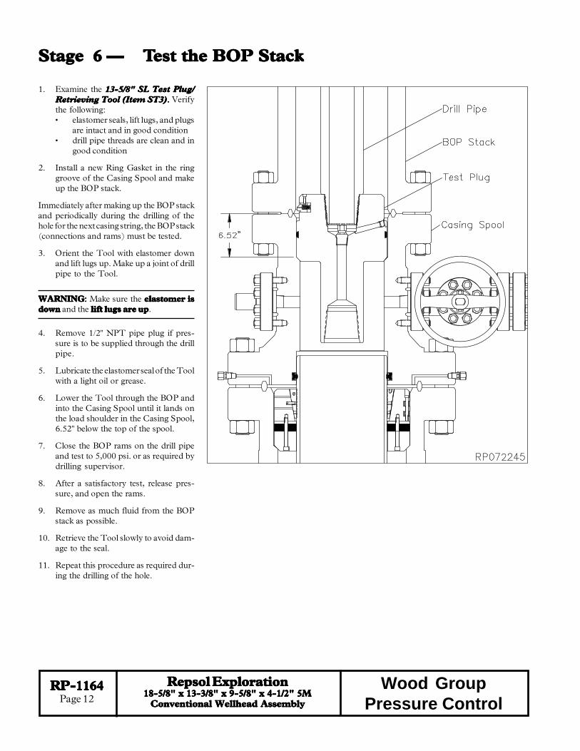
Stage 6 —Stage 6 —Stage 6 —Stage 6 —Stage 6 — TTTTTest the BOP Stackest the BOP Stackest the BOP Stackest the BOP Stackest the BOP Stack
1. Examine the 13-5/8" SL Test Plug/13-5/8" SL Test Plug/13-5/8" SL Test Plug/13-5/8" SL Test Plug/13-5/8" SL Test Plug/Retrieving Tool (Item ST3)Retrieving Tool (Item ST3)Retrieving Tool (Item ST3)Retrieving Tool (Item ST3)Retrieving Tool (Item ST3)..... Verifythe following:• elastomer seals, lift lugs, and plugs
are intact and in good condition• drill pipe threads are clean and in
good condition
2. Install a new Ring Gasket in the ringgroove of the Casing Spool and makeup the BOP stack.
Immediately after making up the BOP stackand periodically during the drilling of thehole for the next casing string, the BOP stack(connections and rams) must be tested.
3. Orient the Tool with elastomer downand lift lugs up. Make up a joint of drillpipe to the Tool.
WARNINGWARNINGWARNINGWARNINGWARNING::::: Make sure the elastomer iselastomer iselastomer iselastomer iselastomer isdowndowndowndowndown and the lift lugs are uplift lugs are uplift lugs are uplift lugs are uplift lugs are up.
4. Remove 1/2" NPT pipe plug if pres-sure is to be supplied through the drillpipe.
5. Lubricate the elastomer seal of the Toolwith a light oil or grease.
6. Lower the Tool through the BOP andinto the Casing Spool until it lands onthe load shoulder in the Casing Spool,6.52" below the top of the spool.
7. Close the BOP rams on the drill pipeand test to 5,000 psi. or as required bydrilling supervisor.
8. After a satisfactory test, release pres-sure, and open the rams.
9. Remove as much fluid from the BOPstack as possible.
10. Retrieve the Tool slowly to avoid dam-age to the seal.
11. Repeat this procedure as required dur-ing the drilling of the hole.

RP-1164RP-1164RP-1164RP-1164RP-1164Page 13
Repsol ExplorationRepsol ExplorationRepsol ExplorationRepsol ExplorationRepsol Exploration18-5/8" x 13-3/8" x 9-5/8" x 4-1/2" 5M18-5/8" x 13-3/8" x 9-5/8" x 4-1/2" 5M18-5/8" x 13-3/8" x 9-5/8" x 4-1/2" 5M18-5/8" x 13-3/8" x 9-5/8" x 4-1/2" 5M18-5/8" x 13-3/8" x 9-5/8" x 4-1/2" 5M
Conventional Wellhead AssemblyConventional Wellhead AssemblyConventional Wellhead AssemblyConventional Wellhead AssemblyConventional Wellhead Assembly
Wood GroupPressure Control
Stage 7 —Stage 7 —Stage 7 —Stage 7 —Stage 7 — Run the Run the Run the Run the Run the WWWWWear Bushingear Bushingear Bushingear Bushingear Bushing
Note: AlwaysNote: AlwaysNote: AlwaysNote: AlwaysNote: Always use a Wear Bushing whiledrilling to protect the load shoulders fromdamage by the drill bit or rotating drill pipe.The Wear Bushing must be retrievedmust be retrievedmust be retrievedmust be retrievedmust be retrieved priorto running the casing.
1. Examine the 13-5/8" Nominal SL Wear13-5/8" Nominal SL Wear13-5/8" Nominal SL Wear13-5/8" Nominal SL Wear13-5/8" Nominal SL WearBushing (Item ST4)Bushing (Item ST4)Bushing (Item ST4)Bushing (Item ST4)Bushing (Item ST4)..... Verify the inter-nal bore is clean and in good condition.
Run the Wear Bushing BeforeRun the Wear Bushing BeforeRun the Wear Bushing BeforeRun the Wear Bushing BeforeRun the Wear Bushing BeforeDrillingDrillingDrillingDrillingDrilling
2. Orient the 13-5/8" SL Test Plug/Re-13-5/8" SL Test Plug/Re-13-5/8" SL Test Plug/Re-13-5/8" SL Test Plug/Re-13-5/8" SL Test Plug/Re-trieving Tool (Item ST3)trieving Tool (Item ST3)trieving Tool (Item ST3)trieving Tool (Item ST3)trieving Tool (Item ST3) with the liftlugs down and the elastomer up.
WARNINGWARNINGWARNINGWARNINGWARNING::::: Make sure the lift lugs arelift lugs arelift lugs arelift lugs arelift lugs aredowndowndowndowndown and the elastomer is upelastomer is upelastomer is upelastomer is upelastomer is up when latchinginto the Wear Bushing.
3. Attach the Tool to a joint of drill pipe.
4. Align the retractable lift lugs of the toolwith the retrieval holes of the bushing andthe carefully lower the Tool into theWear Bushing until the lugs snap intoplace.
Note: If the lugs did not align with the holes,rotate the tool in either direction until theysnap into place.
5. Apply a heavy coat of grease, not dope,to the OD of the bushing.
6. Slowly lower the Tool/Bushing Assem-bly through the BOP stack and land it onthe load shoulder of the casing spool,6.52" below the top of the spool.
7. Remove the Tool from the Wear Bush-ing by rotating the drill pipe counterclockwise 1/4 turn and lifting straight up.
8. Drill as required.
Note: It is highly recommended to retrieve,clean, inspect, grease, and reset the wear bush-ing each time the hole is tripped during thedrilling of the hole section.
Retrieve the Wear Bushing After DrillingRetrieve the Wear Bushing After DrillingRetrieve the Wear Bushing After DrillingRetrieve the Wear Bushing After DrillingRetrieve the Wear Bushing After Drilling
9. Make up the Tool to the drill pipe with the lift lugs down and the elastomer up.
10. Slowly lower the Tool into the Wear Bushing.
11. Pick up and balance the riser weight.
12. Rotate the Tool clockwise until a positive stop is felt. This indicates the lugs havesnapped into the holes in the bushing.
13. Retrieve the Wear Bushing using the elevators if possible, and remove it and the Toolfrom the drill string.

RP-1164RP-1164RP-1164RP-1164RP-1164Page 14
Repsol ExplorationRepsol ExplorationRepsol ExplorationRepsol ExplorationRepsol Exploration18-5/8" x 13-3/8" x 9-5/8" x 4-1/2" 5M18-5/8" x 13-3/8" x 9-5/8" x 4-1/2" 5M18-5/8" x 13-3/8" x 9-5/8" x 4-1/2" 5M18-5/8" x 13-3/8" x 9-5/8" x 4-1/2" 5M18-5/8" x 13-3/8" x 9-5/8" x 4-1/2" 5M
Conventional Wellhead AssemblyConventional Wellhead AssemblyConventional Wellhead AssemblyConventional Wellhead AssemblyConventional Wellhead Assembly
Wood GroupPressure Control
Stage 8 —Stage 8 —Stage 8 —Stage 8 —Stage 8 — Hang Off the 9-5/8" CasingHang Off the 9-5/8" CasingHang Off the 9-5/8" CasingHang Off the 9-5/8" CasingHang Off the 9-5/8" Casing
1. Run the 9-5/8" casing string as requiredand cement in place.
2. Drain the Casing Spool bowl throughthe side outlet.
3. Separate the BOP from the CasingSpool and lift the BOP approximately16" above the Casing Spool and secureBOP with safety slings.
4. Using a fresh water hose, thoroughlywash out the Casing Spool bowl.
Note: Casing Spool side outlet valve toremain open while setting the CasingHanger.
5. Examine the 13-5/8" x 9-5/8" W2 Slip13-5/8" x 9-5/8" W2 Slip13-5/8" x 9-5/8" W2 Slip13-5/8" x 9-5/8" W2 Slip13-5/8" x 9-5/8" W2 SlipCasing Hanger (Item B12)Casing Hanger (Item B12)Casing Hanger (Item B12)Casing Hanger (Item B12)Casing Hanger (Item B12)..... Verifythe following:• slips and internal bore are clean
and in good condition• all screws are in place• packoff rubber is in good condi-
tion• set screws do not protrude inside
slip teeth or outside slip body
Note: Ensure that the packoff rubber doesnot protrude beyond the O.D. of the CasingHanger body. If it is, loosen slightly the capscrews in the bottom of the hanger using a3/8” Allen wrench.
6. There are two latch screws located inthe top of the casing hanger. Using a 5/16” Allen wrench, remove the two latchscrews located 180° apart and separatethe hanger into two halves.
7. Place two boards on the Casing Spoolflange against the casing to support theHanger.
8. Pick up one half of the hanger and placeit around the casing and on top of theboards.
9. Pick up the second hanger half andplace it around the casing adjacent thefirst half.
10. Slide the two hanger halves togetherensuring the slip alignment pins prop-erly engage the opposing hanger half.
11. Reinstall the latch screws and tightensecurely.

RP-1164RP-1164RP-1164RP-1164RP-1164Page 15
Repsol ExplorationRepsol ExplorationRepsol ExplorationRepsol ExplorationRepsol Exploration18-5/8" x 13-3/8" x 9-5/8" x 4-1/2" 5M18-5/8" x 13-3/8" x 9-5/8" x 4-1/2" 5M18-5/8" x 13-3/8" x 9-5/8" x 4-1/2" 5M18-5/8" x 13-3/8" x 9-5/8" x 4-1/2" 5M18-5/8" x 13-3/8" x 9-5/8" x 4-1/2" 5M
Conventional Wellhead AssemblyConventional Wellhead AssemblyConventional Wellhead AssemblyConventional Wellhead AssemblyConventional Wellhead Assembly
Wood GroupPressure Control
Stage 8 —Stage 8 —Stage 8 —Stage 8 —Stage 8 — Hang Off the 9-5/8" CasingHang Off the 9-5/8" CasingHang Off the 9-5/8" CasingHang Off the 9-5/8" CasingHang Off the 9-5/8" Casing
12. Prepare to lower the Hanger into theCasing Spool bowl.
13. Grease the Casing Hanger's body.
14. Using a 5/16” Allen wrench, removeand discard the slip retaining cap screws.
15. Remove the boards and allow thehanger to slide into the Casing Spoolbowl.
Note: The 13-5/8" x 9-5/8" W2 Slip CasingHanger will require a minimum of 72,000lbs. casing load to energize the seal.
16. When the Hanger is down, the top ofthe hanger body will be flush or slightlybelow the top face of the Casing Spoolflange, pull tension on the casing to thedesired hanging weight and then slackoff.
Note:Note:Note:Note:Note: A sharp decrease on the weight indi-cator will signify that the Hanger has takenweight and at what point, If this does notoccur, pull tension again and slack off oncemore.
WARNING: Because of the potential firehazard and the risk of loss of life and prop-erty, It is highly recommended to check thecasing annulus and pipe bore for gas with anapproved sensing device prior to cutting offthe casing. If gas is present, do not use anopen flame torch to cut the casing. It will benecessary to use a air driven mechanicalcutter which is spark free.
17. Rough cut the casing approximately12" above the top flange and move theexcess casing and BOP out of the way.
18. Final cut the casing at 4-3/4" above thetop flange of the casing spool.
19. Grind the casing stub level and thenplace a 3/16" x 3/8" bevel on the O.D.and a I.D. chamfer to match the mini-mum bore of the tubing head to beinstalled.
20. Thoroughly clean the top of the casinghanger and void area above the hanger.Ensure all cutting debris are removed .

RP-1164RP-1164RP-1164RP-1164RP-1164Page 16
Repsol ExplorationRepsol ExplorationRepsol ExplorationRepsol ExplorationRepsol Exploration18-5/8" x 13-3/8" x 9-5/8" x 4-1/2" 5M18-5/8" x 13-3/8" x 9-5/8" x 4-1/2" 5M18-5/8" x 13-3/8" x 9-5/8" x 4-1/2" 5M18-5/8" x 13-3/8" x 9-5/8" x 4-1/2" 5M18-5/8" x 13-3/8" x 9-5/8" x 4-1/2" 5M
Conventional Wellhead AssemblyConventional Wellhead AssemblyConventional Wellhead AssemblyConventional Wellhead AssemblyConventional Wellhead Assembly
Wood GroupPressure Control
Stage 9 —Stage 9 —Stage 9 —Stage 9 —Stage 9 — Install the Install the Install the Install the Install the TTTTTubing Headubing Headubing Headubing Headubing Head
1. Examine the 13-5/8" 5M x 11" 5M T-DBLEBSTubing Head Assembly (Item C1)..... Verify thefollowing:• 'EBS' Secondary Seals are in place and in good
condition• all peripheral equipment is intact and undam-
aged
2. Clean the mating ring grooves of the Casing Spooland the Tubing Head.
3. Lightly lubricate the I.D. of the 9-5/8" EBS" sealsand the casing stub with a light grease.
Note:Note:Note:Note:Note: Excessive grease may prevent a good seal fromforming!
4. Install a new BX-160 Ring Gasket (Item B10) inthe ring groove of the Casing Spool.
5. Orient the Tubing Head so the outlets are in theproper position and then carefully lower the headover the casing stub and land it on the ring gasket.
Warning:Warning:Warning:Warning:Warning: Do Not damage the "EBS" seals or theresealing ability will be impaired!
6. Make up the flange connection with the appropri-ate size Studs and Nuts (Item B11), tighteningthem in an alternating cross pattern.

RP-1164RP-1164RP-1164RP-1164RP-1164Page 17
Repsol ExplorationRepsol ExplorationRepsol ExplorationRepsol ExplorationRepsol Exploration18-5/8" x 13-3/8" x 9-5/8" x 4-1/2" 5M18-5/8" x 13-3/8" x 9-5/8" x 4-1/2" 5M18-5/8" x 13-3/8" x 9-5/8" x 4-1/2" 5M18-5/8" x 13-3/8" x 9-5/8" x 4-1/2" 5M18-5/8" x 13-3/8" x 9-5/8" x 4-1/2" 5M
Conventional Wellhead AssemblyConventional Wellhead AssemblyConventional Wellhead AssemblyConventional Wellhead AssemblyConventional Wellhead Assembly
Wood GroupPressure Control
Stage 9 —Stage 9 —Stage 9 —Stage 9 —Stage 9 — Install the Install the Install the Install the Install the TTTTTubing Headubing Headubing Headubing Headubing Head
noitacoLkaeL noitcA
slaes'SBE'-erobdaehgnibutotnIgnikael
gnibutevomer,erusserpffodeelBlaes'SBE'gnikaelecalperdnadaeh
gnikaelteksaggniR-segnalfneewteB noitcennocegnalfehtnethgitrehtruF
laesregnahgnisaC-sulunnagnisaCgnikaeltnemele
gnibutevomer,erusserpffodeelBhtiwspilsteserdnagnisacraeps,daeh
dnadaehgnibutllatsier,daolrehgihtseter
Flange TestFlange TestFlange TestFlange TestFlange Test
1. Locate the remaining "FLG TEST"fittings on the Tubing Head lower flangeand remove the dust cap from the fit-ting.
2. Attach a Hydraulic Test Pump to theopen fitting and pump clean test fluidinto the void until a continuous streamflows from the Bleeder Tool.
3. Close the bleeder tool and continuepumping test fluid until a test pressureequal the working pressure of the tub-ing head lower flange until a test pres-sure 5,000 psi or 80% of Casing Col-lapse Pressure is Attained - which- - which- - which- - which- - which-ever is lessever is lessever is lessever is lessever is less.
4. Hold the test pressure for fifteen (15)minutes or as desired by the drillingsupervisor.
5. If pressure drops a leak has developed.Take the appropriate action in the ad-jacent table.
6. Repeat steps 1 - 6 until a satisfactorytest is achieved.
7. When a satisfactory test is achieved,remove Test Pump, drain test fluid,and reinstall the dust caps on the openfittings.
Seal TestSeal TestSeal TestSeal TestSeal Test
1. Locate the "SEAL TEST" fitting andone "FLG TEST" fitting on the TubingHead lower flange and remove the dustcap from both fittings.
2. Attach a Bleeder Tool to one of theopen "FLG TEST" fitting and open theTool.
3. Attach a Hydraulic Test Pump to theother open fitting and pump clean testfluid between the EBS Seals until a testpressure 5,000 psi or 80% of CasingCollapse Pressure is Attained - - - - -whichever is lesswhichever is lesswhichever is lesswhichever is lesswhichever is less.
4. Hold the test pressure for fifteen (15)minutes or as desired by the drillingsupervisor.
5. If pressure drops a leak has developed.Take the appropriate action in the tablebelow.
7. Repeat steps 1 - 6 until a satisfactorytest is achieved.
8. When a satisfactory test is achieved,remove Test Pump, drain test fluid,and reinstall the dust cap on the open"SEAL TEST" fitting.

RP-1164RP-1164RP-1164RP-1164RP-1164Page 18
Repsol ExplorationRepsol ExplorationRepsol ExplorationRepsol ExplorationRepsol Exploration18-5/8" x 13-3/8" x 9-5/8" x 4-1/2" 5M18-5/8" x 13-3/8" x 9-5/8" x 4-1/2" 5M18-5/8" x 13-3/8" x 9-5/8" x 4-1/2" 5M18-5/8" x 13-3/8" x 9-5/8" x 4-1/2" 5M18-5/8" x 13-3/8" x 9-5/8" x 4-1/2" 5M
Conventional Wellhead AssemblyConventional Wellhead AssemblyConventional Wellhead AssemblyConventional Wellhead AssemblyConventional Wellhead Assembly
Wood GroupPressure Control
Stage 10 —Stage 10 —Stage 10 —Stage 10 —Stage 10 — TTTTTesting the BOP Stackesting the BOP Stackesting the BOP Stackesting the BOP Stackesting the BOP Stack
Immediately after making up the BOP stackand periodically during the conditioning ofthe well for the completion, the BOP stack(connections and rams) must be tested.
1. Examine the 11" Nominal SL Test/11" Nominal SL Test/11" Nominal SL Test/11" Nominal SL Test/11" Nominal SL Test/Plug Retrieving Tool(Item ST5).Plug Retrieving Tool(Item ST5).Plug Retrieving Tool(Item ST5).Plug Retrieving Tool(Item ST5).Plug Retrieving Tool(Item ST5).Verify the following:• elastomer seals, lift lugs, and plugs
are intact and in good condition• drill pipe threads are clean and in
good condition
2. Install a new Ring Gasket in the ringgroove of the Tubing Head and make upthe BOP stack.
3. Orient the Tool with elastomer downand lift lugs up. Make up a joint of drillpipe with the appropriate crossover tothe Tool.
WARNINGWARNINGWARNINGWARNINGWARNING::::: Make sure the elastomer iselastomer iselastomer iselastomer iselastomer isdowndowndowndowndown and the lift lugs are uplift lugs are uplift lugs are uplift lugs are uplift lugs are up.
4. Remove 1/2" NPT pipe plug if pressureis to be supplied through the drill pipe.
5. Lubricate the elastomer seal of the Toolwith a light oil or grease.
6. Retract all tubing head lockscrews andthen carefully lower the Tool throughthe BOP until it lands on the load shoul-der in the Tubing Head, 10.0" below thetop of the Tubing Head.
7. Close the BOP rams on the pipe andtest to 5,000 psi. or as required bydrilling supervisor.
Note: Any leakage past the Tool will bemonitored at the open side outlet valve.
8. After a satisfactory test, release pres-sure, and open the rams.
9. Remove as much fluid from the BOP stack as possible.
10. Retrieve the Tool slowly to avoid damage to the seal.
Note: When performing the BOP blind ram test it is highly recommended to suspend astand of drill pipe below the tool to ensure the tool stays in place while disconnecting fromit with the drill pipe.
11. Repeat this procedure as required during the completion of the well.

RP-1164RP-1164RP-1164RP-1164RP-1164Page 19
Repsol ExplorationRepsol ExplorationRepsol ExplorationRepsol ExplorationRepsol Exploration18-5/8" x 13-3/8" x 9-5/8" x 4-1/2" 5M18-5/8" x 13-3/8" x 9-5/8" x 4-1/2" 5M18-5/8" x 13-3/8" x 9-5/8" x 4-1/2" 5M18-5/8" x 13-3/8" x 9-5/8" x 4-1/2" 5M18-5/8" x 13-3/8" x 9-5/8" x 4-1/2" 5M
Conventional Wellhead AssemblyConventional Wellhead AssemblyConventional Wellhead AssemblyConventional Wellhead AssemblyConventional Wellhead Assembly
Wood GroupPressure Control
Stage 11 —Stage 11 —Stage 11 —Stage 11 —Stage 11 — Run the Run the Run the Run the Run the WWWWWear Bushingear Bushingear Bushingear Bushingear Bushing
Note: AlwaysNote: AlwaysNote: AlwaysNote: AlwaysNote: Always use a Wear Bushing whiledrilling to protect the load shoulders fromdamage by the drill bit or rotating drill pipe.The Wear Bushing must be retrievedmust be retrievedmust be retrievedmust be retrievedmust be retrieved priorto running the casing.
1. Examine the 11" Nominal SL Wear11" Nominal SL Wear11" Nominal SL Wear11" Nominal SL Wear11" Nominal SL WearBushing (Item ST6)Bushing (Item ST6)Bushing (Item ST6)Bushing (Item ST6)Bushing (Item ST6)..... Verify the in-ternal bore is clean and in good condi-tion.
Run the Wear BushingRun the Wear BushingRun the Wear BushingRun the Wear BushingRun the Wear BushingBefore DrillingBefore DrillingBefore DrillingBefore DrillingBefore Drilling
2. Orient the 11" SL Test Plug/Retriev-11" SL Test Plug/Retriev-11" SL Test Plug/Retriev-11" SL Test Plug/Retriev-11" SL Test Plug/Retriev-ing Tool (Item ST5)ing Tool (Item ST5)ing Tool (Item ST5)ing Tool (Item ST5)ing Tool (Item ST5) with the lift lugsdown and the elastomer up.
WARNINGWARNINGWARNINGWARNINGWARNING::::: Make sure the lift lugs arelift lugs arelift lugs arelift lugs arelift lugs aredowndowndowndowndown and the elastomer is upelastomer is upelastomer is upelastomer is upelastomer is up when latch-ing into the Wear Bushing.
3. Attach the Tool to a joint of drill pipe.
4. Align the retractable lift lugs of the toolwith the retrieval holes of the bushingand the carefully lower the Tool intothe Wear Bushing until the lugs snapinto place.
Note: If the lugs did not align with the holes,rotate the tool in either direction until theysnap into place.
5. Apply a heavy coat of grease, not dope,to the OD of the bushing and fullyretract all tubing head lockscrews.
6. Slowly lower the Tool/Bushing Assem-bly through the BOP stack and land iton the load shoulder of the tubing head,10.0" below the top of the spool.
7. Locate and run in two tubing headlockscrews 180° apart snug tight toretain the wear bushing.
8. Remove the Tool from the Wear Bush-ing by rotating the drill pipe counterclockwise 1/4 turn and lifting straightup.
9. Drill as required.
Note: It is highly recommended to retrieve, clean, inspect, grease, and reset the wearbushing each time the hole is tripped during the drilling of the hole section.
Retrieve the Wear Bushing After DrillingRetrieve the Wear Bushing After DrillingRetrieve the Wear Bushing After DrillingRetrieve the Wear Bushing After DrillingRetrieve the Wear Bushing After Drilling
10. Make up the Tool to the drill pipe with the lift lugs down and the elastomer up.
11. Slowly lower the Tool into the Wear Bushing.
12. Pick up and balance the riser weight.
13. Rotate the Tool clockwise until a positive stop is felt. This indicates the lugs havesnapped into the holes in the bushing.
14. Retract all lockscrews and then retrieve the Wear Bushing using the elevators ifpossible, and remove it and the Tool from the drill string.

RP-1164RP-1164RP-1164RP-1164RP-1164Page 20
Repsol ExplorationRepsol ExplorationRepsol ExplorationRepsol ExplorationRepsol Exploration18-5/8" x 13-3/8" x 9-5/8" x 4-1/2" 5M18-5/8" x 13-3/8" x 9-5/8" x 4-1/2" 5M18-5/8" x 13-3/8" x 9-5/8" x 4-1/2" 5M18-5/8" x 13-3/8" x 9-5/8" x 4-1/2" 5M18-5/8" x 13-3/8" x 9-5/8" x 4-1/2" 5M
Conventional Wellhead AssemblyConventional Wellhead AssemblyConventional Wellhead AssemblyConventional Wellhead AssemblyConventional Wellhead Assembly
Wood GroupPressure Control
1. Run the 4-1/2" production tubing string to the required depthand space out appropriately.
2. Examine the 11" Nominal x 4-1/2" New Vam, WG-T-M5611" Nominal x 4-1/2" New Vam, WG-T-M5611" Nominal x 4-1/2" New Vam, WG-T-M5611" Nominal x 4-1/2" New Vam, WG-T-M5611" Nominal x 4-1/2" New Vam, WG-T-M56Tubing Hanger (Item C10) Tubing Hanger (Item C10) Tubing Hanger (Item C10) Tubing Hanger (Item C10) Tubing Hanger (Item C10) . Verify the following:• packoff rubber is intact and undamaged• bore and internal threads are clean and undamaged• tapered seal neck and o-ring are clean and undamaged
3. Thoroughly clean and lightly lubricate the hanger seal neck andI.D. of the M56 Protector Cap (Item ST7) with oil or a lightgrease.
4. Carefully slide the protector cap over the hanger neck, allow-ing the internal o-ring to retain the cap in place.
Stage 12 —Stage 12 —Stage 12 —Stage 12 —Stage 12 — Hang Off the 4-1/2" Hang Off the 4-1/2" Hang Off the 4-1/2" Hang Off the 4-1/2" Hang Off the 4-1/2" TTTTTubingubingubingubingubing
5. Make up a short handling joint in the top of the hanger andtighten securely
6. At a predetermined position in the tubing string, set the tubingin the floor slips. Pick up the WG T-M56 Tubing Hanger andmake it up in the tubing string. Torque the tubing hanger to thethread manufacturer's optimum make up torque.
7. Pick up the tubing string so that the bottom of the hanger isapproximately 5 feet above the rig floor and reset the floorslips.
8. Remove the handling joint and install the appropriate lengthlanding joint in the top of the hanger and torque the landingjoint to the thread manufacturer's minimum make up torque.

RP-1164RP-1164RP-1164RP-1164RP-1164Page 21
Repsol ExplorationRepsol ExplorationRepsol ExplorationRepsol ExplorationRepsol Exploration18-5/8" x 13-3/8" x 9-5/8" x 4-1/2" 5M18-5/8" x 13-3/8" x 9-5/8" x 4-1/2" 5M18-5/8" x 13-3/8" x 9-5/8" x 4-1/2" 5M18-5/8" x 13-3/8" x 9-5/8" x 4-1/2" 5M18-5/8" x 13-3/8" x 9-5/8" x 4-1/2" 5M
Conventional Wellhead AssemblyConventional Wellhead AssemblyConventional Wellhead AssemblyConventional Wellhead AssemblyConventional Wellhead Assembly
Wood GroupPressure Control
9. Calculate the distance from the top of thetubing head to the top of the rig floor and add10.0". Record this dimension.
Landing the Tubing HangerLanding the Tubing HangerLanding the Tubing HangerLanding the Tubing HangerLanding the Tubing Hanger
10. Drain the BOP and riser through the tubinghead side outlet valve. Retract all lockscrews,and then flush the tubing bowl with clean freshwater to remove any debris that may keep thehanger from properly landing.
Note: Side outlet valve to remain open whilelanding the tubing hanger.
11. Thoroughly clean and lightly lubricate thehanger packoff rubber with oil or a light grease.
12. Pick up the tubing string and remove the floorslips.
13. Carefully lower the tubing hanger into thewell, tallying the tubing every five feet to therecorded dimension. Place a paint mark on thelanding joint at the proper elevation of therecorded dimension.
14. Continue lowering the tubing into the well andland the hanger on the load shoulder in thetubing head and slack off all weight.
15. Run in all the tubing head lockscrews in analternating cross pattern to refusal.
16. After all wire line work is completed, removethe landing joint by rotating the joint to the leftuntil it comes free of the hanger and thenretrieve it with a straight lift.
17. Using a dry rod, install the 4" One-WayBack Pressure Valve (Item ST8) in thetubing hanger bore.
18. With the back pressure valve set, nipple downthe BOP.
Stage 12 —Stage 12 —Stage 12 —Stage 12 —Stage 12 — Hang Off the 4-1/2" Hang Off the 4-1/2" Hang Off the 4-1/2" Hang Off the 4-1/2" Hang Off the 4-1/2" TTTTTubingubingubingubingubing

RP-1164RP-1164RP-1164RP-1164RP-1164Page 22
Repsol ExplorationRepsol ExplorationRepsol ExplorationRepsol ExplorationRepsol Exploration18-5/8" x 13-3/8" x 9-5/8" x 4-1/2" 5M18-5/8" x 13-3/8" x 9-5/8" x 4-1/2" 5M18-5/8" x 13-3/8" x 9-5/8" x 4-1/2" 5M18-5/8" x 13-3/8" x 9-5/8" x 4-1/2" 5M18-5/8" x 13-3/8" x 9-5/8" x 4-1/2" 5M
Conventional Wellhead AssemblyConventional Wellhead AssemblyConventional Wellhead AssemblyConventional Wellhead AssemblyConventional Wellhead Assembly
Wood GroupPressure Control
1. Remove the Tubing Hanger Protector Cap with a straightvertical lift.
2. Using a high pressure water hose, thoroughly clean the top ofthe Tubing Head and the Tubing Hanger and blow dry withcompressed air.
3. Carefully inspect the neck of the hanger for any damage andrepair as necessary. Replace the o-ring if necessary.
4. Lightly lubricate the ring groove of the tubing head and thetapered neck seal area of the hanger with oil or a light grease.
5. Place a new RX-54 Ring Gasket in the ring groove of theTubing Head and fill the void above the hanger with clean testfluid.
Stage 13 —Stage 13 —Stage 13 —Stage 13 —Stage 13 — Install Production Install Production Install Production Install Production Install Production TTTTTreereereereeree
6. Examine the Single Production Tree with M56 AdapterSingle Production Tree with M56 AdapterSingle Production Tree with M56 AdapterSingle Production Tree with M56 AdapterSingle Production Tree with M56 AdapterFlangeFlangeFlangeFlangeFlange..... Verify the following:• internal bore and seal pocket are clean and in good condi-
tion• all valves, handwheels and actuators are in place and in
good condition
7. Lightly lubricate the Tree adapter flange seal pocket and ringgroove with oil or a light grease.
8. Align and level the Tree Assembly over the Tubing Head.
9. Carefully lower the assembly over the Tubing Hanger neck andthen land the assembly on the ring gasket.
10. Make up the flange connection using the adapter studs andnuts, tightening them in an alternating cross pattern.

RP-1164RP-1164RP-1164RP-1164RP-1164Page 23
Repsol ExplorationRepsol ExplorationRepsol ExplorationRepsol ExplorationRepsol Exploration18-5/8" x 13-3/8" x 9-5/8" x 4-1/2" 5M18-5/8" x 13-3/8" x 9-5/8" x 4-1/2" 5M18-5/8" x 13-3/8" x 9-5/8" x 4-1/2" 5M18-5/8" x 13-3/8" x 9-5/8" x 4-1/2" 5M18-5/8" x 13-3/8" x 9-5/8" x 4-1/2" 5M
Conventional Wellhead AssemblyConventional Wellhead AssemblyConventional Wellhead AssemblyConventional Wellhead AssemblyConventional Wellhead Assembly
Wood GroupPressure Control
Flange TestFlange TestFlange TestFlange TestFlange Test
1. Locate the two "FLG TEST" fitting onthe adapter flange and remove the dustcap from each fitting.
2. Attach a bleeder tool to one of the openfittings and open the tool.
3. Attach a Hydraulic Test Pump to theother open fitting and pump clean testfluid into the flange connection until acontinuous stream flows from theBleeder Tool.
4. Close the Bleeder Tool and continuepumping test fluid until a stable pres-sure of 5,000 psi is attained
5. Hold the test pressure for fifteen (15)minutes or as desired by the drillingsupervisor.
6. If pressure drops a leak has developed.Take the appropriate action in the ad-jacent table.
7. Repeat steps 2 - 6 until a satisfactorytest is achieved.
8. When a satisfactory test is achieved,bleed off flange test pressure, removeTest Pump and Bleeder Tool, draintest fluid, and reinstall the dust cap onthe open "FLG TEST" fittings.
noitacoLkaeL noitcA
gnikaelteksaggniR-segnalfneewteB noitcennocegnalfehtnethgitrehtruF
gnikaelgnikcaP-swercskcoLdnuorA stundnalgwercskcolnethgitrehtruF
laesregnaH-sulunnagnibutotnIgnikaeltnemele
swercskcolehtnethgitrehtruF
laeskcenregnaH-erobeertotnIgnikael
,noitcennocegnalfehtnethgitrehtruFeertevomer,seunitnockaelfi,tseter
dnagniR-Olaeskcenecalperdnakcenlaesregnahdereppatriaper
Stage 13 —Stage 13 —Stage 13 —Stage 13 —Stage 13 — Install Production Install Production Install Production Install Production Install Production TTTTTreereereereeree

RP-1164RP-1164RP-1164RP-1164RP-1164Page 24
Repsol ExplorationRepsol ExplorationRepsol ExplorationRepsol ExplorationRepsol Exploration18-5/8" x 13-3/8" x 9-5/8" x 4-1/2" 5M18-5/8" x 13-3/8" x 9-5/8" x 4-1/2" 5M18-5/8" x 13-3/8" x 9-5/8" x 4-1/2" 5M18-5/8" x 13-3/8" x 9-5/8" x 4-1/2" 5M18-5/8" x 13-3/8" x 9-5/8" x 4-1/2" 5M
Conventional Wellhead AssemblyConventional Wellhead AssemblyConventional Wellhead AssemblyConventional Wellhead AssemblyConventional Wellhead Assembly
Wood GroupPressure Control
IntegIntegIntegIntegIntegral Lockscrew Operaral Lockscrew Operaral Lockscrew Operaral Lockscrew Operaral Lockscrew Operationtiontiontiontion
Lockscrew Operation InstructionsLockscrew Operation InstructionsLockscrew Operation InstructionsLockscrew Operation InstructionsLockscrew Operation Instructions
These instructions are applicable to ONLY WGPC "Integral" style lockscrews. This procedure does not cover lockscrews manufacturedor installed in wellhead equipment not supplied by WGPC.
1. The Integral Lockscrew is threaded into the Glandnut of the assembly with enough thread to back out clear of the bowl or to extendinto the bowl. This will not disturb the seal/packing around the lockscrew shaft.
2. The seal around the shaft is a compression type with metal Junk Rings. The Packing is energized with the Glandnut on the outsidediameter of the flange and isolates the lockscrew threads from the well bore.
3. The lockscrew is normally backed out of the bowl. The lockscrews are extended into the bowl only after a hanger has been installed.The lockscrew must be backed out prior to removing the hanger.
4. To properly operate the lockscrew it is required to place a backup wrench on the gland nut, rotate the lockscrew in or out as required.In new installations the Glandnut torque is preset and should not be backed off to operate the lockscrew. The Glandnut, when properlyinstalled, should not expose more than 3 external threads past the OD of the wellhead.
5. When replacing the lockscrew assembly, the junk rings and packing are to be placed in the lockscrew prep as indicated followed bythe lockscrew/Gland nut assembly. The Gland nut is then torqued as required. Once the Glandnut torque is met, the Lockscrew maybe operated as required.
Under no circumstances is the Glandnut to be backed off to operate the lockscrew.
Always use the appropriate size box wrench or socket to rotate the Lockscrew. Do not use a pipe wrench.
For lockscrew or lockscrew packing replacement instruction, refer to OM-044.
Junk Rings
Lockscrew
No More than 3 Threads of GlandnutExposed Past OD of Flange
Turn LockscrewClockwise to Engage
Clockwise to RetractTurn Lockscrew Counter-
Hold Backupon Glandnut
Gland Nut
RP050425
Hold Backupon Glandnut
Typical WGPC Integral Lockscrew Configuration
Packing
Engaged
Retracted

RP-1164RP-1164RP-1164RP-1164RP-1164Page 25
Repsol ExplorationRepsol ExplorationRepsol ExplorationRepsol ExplorationRepsol Exploration18-5/8" x 13-3/8" x 9-5/8" x 4-1/2" 5M18-5/8" x 13-3/8" x 9-5/8" x 4-1/2" 5M18-5/8" x 13-3/8" x 9-5/8" x 4-1/2" 5M18-5/8" x 13-3/8" x 9-5/8" x 4-1/2" 5M18-5/8" x 13-3/8" x 9-5/8" x 4-1/2" 5M
Conventional Wellhead AssemblyConventional Wellhead AssemblyConventional Wellhead AssemblyConventional Wellhead AssemblyConventional Wellhead Assembly
Wood GroupPressure Control
1.1 .1 .1 .1 . Introduction and ScopeIntroduction and ScopeIntroduction and ScopeIntroduction and ScopeIntroduction and Scope..... The following recommended pro-cedure has been prepared with particular regard to attainingpressure-tight weld when attaching casing heads, flanges, etc.,to casing. Although most of the high strength casing used (suchas N-80) is not normally considered field weldable, somesuccess may be obtained by using the following or similarprocedures.
Caution:Caution:Caution:Caution:Caution: In some wellheads, the seal weld is also a structuralweld and can be subjected to high tensile stresses. Consider-ation must therefore be given by competent authority to themechanical properties of the weld and its heat affected zone.
a.a.a.a.a. The steels used in wellhead parts and in casing are highstrength steels that are susceptible to cracking when welded. Itis imperative that the finished weld and adjacent metal be freefrom cracks. The heat from welding also affects the mechanicalproperties. This is especially serious if the weld is subjected toservice tension stresses.
b.b.b.b.b. This procedure is offered only as a recommendation. Theresponsibility for welding lies with the user and results arelargely governed by the welder's skill. Weldability of the severalmakes and grades of casing varies widely, thus placing addedresponsibility on the welder. Transporting a qualified welder tothe job, rather than using a less-skilled man who may be at hand,will, in most cases, prove economical. The responsible operat-ing representative should ascertain the welder's qualificationsand, if necessary, assure himself by instruction or demonstra-tion, that the welder is able to perform the work satisfactorily.
2.2.2.2.2. Welding Conditions.Welding Conditions.Welding Conditions.Welding Conditions.Welding Conditions. Unfavorable welding conditions mustbe avoided or minimized in every way possible, as even themost skilled welder cannot successfully weld steels that aresusceptible to cracking under adverse working conditions, orwhen the work is rushed. Work above the welder on the drillingfloor should be avoided> The weld should be protected fromdripping mud, water, and oil and from wind, rain, or otheradverse weather conditions. The drilling mud, water, or otherfluids must be lowered in the casing and kept at a low level untilthe weld has properly cooled. It is the responsibility of the userto provide supervision that will assure favorable workingconditions, adequate time, and the necessary cooperation of therig personnel.
3.3.3.3.3. WeldingWeldingWeldingWeldingWelding..... The welding should be done by the shielded metal-arc or other approved process.
4.4.4.4.4. Filler MetalFiller MetalFiller MetalFiller MetalFiller Metal..... The root pass can be made either with an E6010or E7018 electrode. E6010 electrodes offer good penetrationand weld deposit ductility, but have a relatively high intrinsichydrogen content. Low-hydrogen E7018 electrodes are lesssusceptible to hydrogen-induced root cracking. After the rootpass, low hydrogen electrodes or filler wires of a yield strengthequal to the casing yield strength should be used. The lowhydrogen electrodes include classes EXX15, EXX16, EXX18,EXX28 of AWS A5.1 (latest edition): Mild Steel Covered Arc-Welding Electrodes* and AWS A5.5 (latest edition): Low-AlloySteel Covered Arc-Welding Electrodes*. Low hydrogen elec-trodes should not be exposed to the atmosphere until ready foruse. Electrodes exposed to atmosphere should be dried 1 to 2hours at 500 to 600°F (260 to 316°C) just before use.
5.5.5.5.5. Preparation of Base Metal.Preparation of Base Metal.Preparation of Base Metal.Preparation of Base Metal.Preparation of Base Metal. The area to be welded should bedry and free of any paint, grease, scale, rust or dirt.
6.6.6.6.6. PreheatingPreheatingPreheatingPreheatingPreheating..... Both the casing and the wellhead member shouldbe preheated to 200 to 300°F (93 to 149°C) for a distance of atleast 3 inches (76.2 mm) on either side of the weld location,using a suitable preheating torch. Before applying preheat, thefluid should be bailed out of the casing to a point several inches(mm) below the weld location. The preheat temperatureshould be checked by the use of heat sensitive crayons. Specialattention must be given to preheating the thick sections ofwellhead parts to be welded, to insure uniform heating andexpansion with respect to the relatively thin casing.
Recommended Procedure for Field Recommended Procedure for Field Recommended Procedure for Field Recommended Procedure for Field Recommended Procedure for Field WWWWWelding Pipe to elding Pipe to elding Pipe to elding Pipe to elding Pipe to WWWWWell-ell-ell-ell-ell-head Phead Phead Phead Phead Parararararts for Pressure Sealts for Pressure Sealts for Pressure Sealts for Pressure Sealts for Pressure Seal

RP-1164RP-1164RP-1164RP-1164RP-1164Page 26
Repsol ExplorationRepsol ExplorationRepsol ExplorationRepsol ExplorationRepsol Exploration18-5/8" x 13-3/8" x 9-5/8" x 4-1/2" 5M18-5/8" x 13-3/8" x 9-5/8" x 4-1/2" 5M18-5/8" x 13-3/8" x 9-5/8" x 4-1/2" 5M18-5/8" x 13-3/8" x 9-5/8" x 4-1/2" 5M18-5/8" x 13-3/8" x 9-5/8" x 4-1/2" 5M
Conventional Wellhead AssemblyConventional Wellhead AssemblyConventional Wellhead AssemblyConventional Wellhead AssemblyConventional Wellhead Assembly
Wood GroupPressure Control
7.7.7.7.7. Welding TechniqueWelding TechniqueWelding TechniqueWelding TechniqueWelding Technique..... Use a 1/8 or 5/32-inch (3.2 or 4.0 mm)E6010 or E7018 electrode and step weld the first bead (rootpass); that, weld approximately 2 to 4 inches (50 to 100 mm)and then move diametrically opposite this point and weld 2 to4 inches (50 to 100 mm) halfway between the first two welds,move diametrically opposite this weld, and so on until the firstpass is completed. This second pass should be made with a 5/32-inch (4.0 mm) low hydrogen electrode of the properstrength and may be continuous. The balance of the weldinggroove may then be filled with continuous passes without backstepping or lacing, using a 3/16-inch (4.8 mm) low hydrogenelectrode. All beads should be stringer beads with good pen-etration. There should be no undercutting and weld shall beworkmanlike in appearance.
a.a.a.a.a. Test ports should be open when welding is performed toprevent pressure buildup within the test cavity.
b.b.b.b.b. During welding the temperature of the base metal oneither side of the weld should be maintained at 200 to 300°F (93to 149°C).
c.c.c.c.c. Care should be taken to insure that the welding cable isproperly grounded to the casing, but ground wire should not bewelded to the casing or the wellhead. Ground wire should befirmly clamped to the casing, the wellhead, or fixed in positionbetween pipe slips. Bad contact may cause sparking, withresultant hard spots beneath which incipient cracks may de-velop. The welding cable should not be grounded to the steelderrick, nor to the rotary-table base.
8.8.8.8.8. CleaningCleaningCleaningCleaningCleaning..... All slag or flux remaining on any welding beadshould be removed before laying the next bead. This alsoapplies to the completed weld.
9.9.9.9.9. DefectsDefectsDefectsDefectsDefects..... Any cracks or blow holes that appear on any beadshould be removed to sound metal by chipping or grindingbefore depositing the next bead.
10.10.10.10.10. Postheating.Postheating.Postheating.Postheating.Postheating. To prevent damage to packing a temperature of275°F (135°C) to 300°F (149°C) for no less than one hourfollowed by a slow cool is a minimum requirement.
11.11.11.11.11. Cooling.Cooling.Cooling.Cooling.Cooling. Rapid cooling must be avoided. To assure slowcooling, welds should be protected from extreme weatherconditions (cold, rain, high winds, etc.) by the use of suitableinsulating material. (Specially designed insulating blankets areavailable at many welding supply stores.) Particular attentionshould be given to maintaining uniform cooling of the thicksections of the wellhead parts and the relatively thin casing, asthe relatively thin casing will pull away from the head or hangerif allowed to cool more rapidly. The welds should cool in air toless than 200°F (93°C) (measured with a heat sensitive crayon)prior to permitting the mud to rise in the casing.
12.12.12.12.12. Test the WeldTest the WeldTest the WeldTest the WeldTest the Weld..... After cooling, test the weld. The weld must becool otherwise the test media will crack the weld. The testpressure should be no more than 80% of the casing collapsepressure. refer to the follow chart for approved testing media.
Recommended Procedure for Field Recommended Procedure for Field Recommended Procedure for Field Recommended Procedure for Field Recommended Procedure for Field WWWWWelding Pipe to elding Pipe to elding Pipe to elding Pipe to elding Pipe to WWWWWell-ell-ell-ell-ell-head Phead Phead Phead Phead Parararararts for Pressure Seal (continued)ts for Pressure Seal (continued)ts for Pressure Seal (continued)ts for Pressure Seal (continued)ts for Pressure Seal (continued)
aideMtseT
saideMelbatpeccA saideMelbatpeccanU
retaWliOelbauloSretaW
saGtrenInegortiN
saGnogrA
negyxOenelytecA
liOciluardyHliOrotoM
diulFkcarB