yamaha nouvo s 115 top 10 - shad yamaha nouvo s 115 ‘09 kit topmaster 4 y0nv19st montar la pieza...
TRANSCRIPT
YA
MA
HA
NO
UV
O S
115
‘09
KIT
TO
PM
AS
TE
R
Y0N
V19
ST
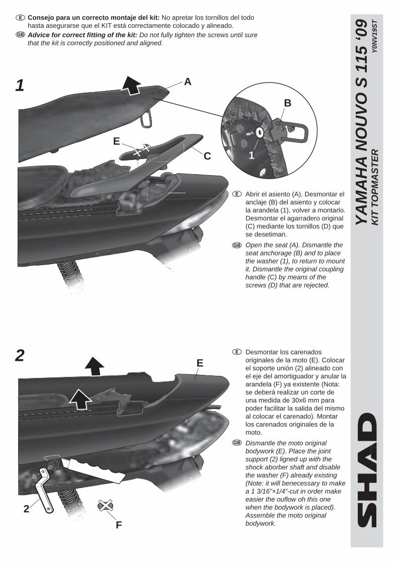
Consejo para un correcto montaje del kit: No apretar los tornillos del todo hasta asegurarse que el KIT está correctamente colocado y alineado. Advice for correct fitting of the kit: Do not fully tighten the screws until sure that the kit is correctly positioned and aligned.
Abrir el asiento (A). Desmontar el anclaje (B) del asiento y colocar la arandela (1), volver a montarlo. Desmontar el agarradero original (C) mediante los tornillos (D) que se desetiman.
Open the seat (A). Dismantle the seat anchorage (B) and to place the washer (1), to return to mount it. Dismantle the original coupling handle (C) by means of the screws (D) that are rejected.
Desmontar los carenados originales de la moto (E). Colocar el soporte unión (2) alineado con el eje del amortiguador y anular la arandela (F) ya existente (Nota: se deberá realizar un corte de una medida de 30x6 mm para poder facilitar la salida del mismo al colocar el carenado). Montar los carenados originales de la moto.
Dismantle the moto original bodywork (E). Place the joint support (2) ligned up with the shock aborber shaft and disable the washer (F) already existing (Note: it will benecessary to make a 1 3/16”×1/4”-cut in order make easier the ouflow oh this one when the bodywork is placed). Assemble the moto original bodywork.
2
1
C
A
E
B
111
E
2
F
3
4
YA
MA
HA
NO
UV
O S
115
‘09
KIT
TO
PM
AS
TE
R
Y0N
V19
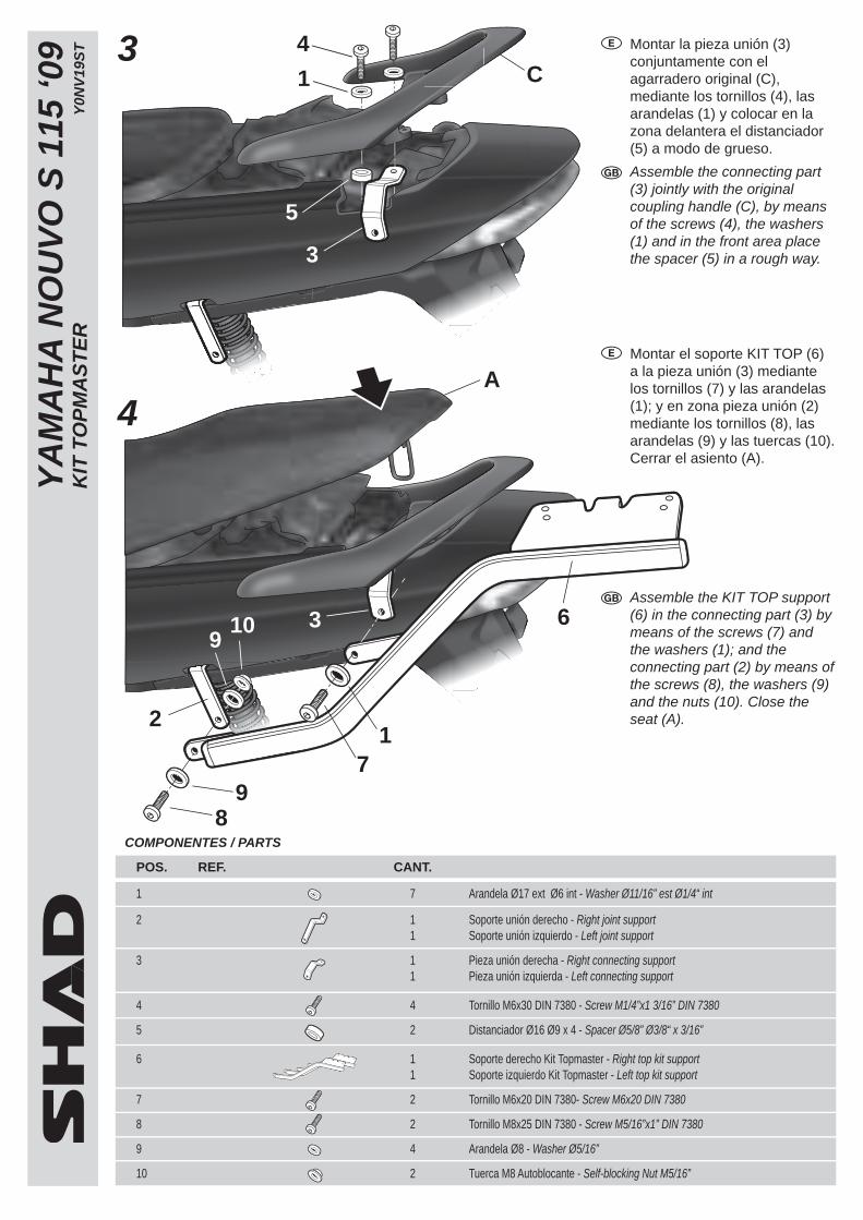
ST Montar la pieza unión (3)
conjuntamente con el agarradero original (C), mediante los tornillos (4), las arandelas (1) y colocar en la zona delantera el distanciador (5) a modo de grueso.
Assemble the connecting part (3) jointly with the original coupling handle (C), by means of the screws (4), the washers (1) and in the front area place the spacer (5) in a rough way.
Montar el soporte KIT TOP (6) a la pieza unión (3) mediante los tornillos (7) y las arandelas (1); y en zona pieza unión (2) mediante los tornillos (8), las arandelas (9) y las tuercas (10). Cerrar el asiento (A).
Assemble the KIT TOP support (6) in the connecting part (3) by means of the screws (7) and the washers (1); and the connecting part (2) by means of the screws (8), the washers (9) and the nuts (10). Close the seat (A).
POS. REF. CANT.
1 7 Arandela Ø17 ext Ø6 int - Washer Ø11/16” est Ø1/4“ int
2 1 Soporte unión derecho - Right joint support 1 Soporte unión izquierdo - Left joint support
3 1 Pieza unión derecha - Right connecting support 1 Pieza unión izquierda - Left connecting support
4 4 Tornillo M6x30 DIN 7380 - Screw M1/4”x1 3/16” DIN 7380
5 2 Distanciador Ø16 Ø9 x 4 - Spacer Ø5/8” Ø3/8“ x 3/16”
6 1 Soporte derecho Kit Topmaster - Right top kit support 1 Soporte izquierdo Kit Topmaster - Left top kit support
7 2 Tornillo M6x20 DIN 7380- Screw M6x20 DIN 7380
8 2 Tornillo M8x25 DIN 7380 - Screw M5/16”x1” DIN 7380
9 4 Arandela Ø8 - Washer Ø5/16”
10 2 Tuerca M8 Autoblocante - Self-blocking Nut M5/16”
COMPONENTES / PARTS
C4
1
5
3
3109
A
6
17
9
2
8