zxmp s325(v2.00) operation instructions
TRANSCRIPT

ZXMP S325SDH Based Multi-Service Node Equipment
Operation Instructions
Version 2.00
ZTE CORPORATION ZTE Plaza, Keji Road South, Hi-Tech Industrial Park, Nanshan District, Shenzhen, P. R. China 518057 Tel: (86) 755 26771900 800-9830-9830 Fax: (86) 755 26772236 URL: http://support.zte.com.cn E-mail: [email protected]

LEGAL INFORMATION Copyright © 2006 ZTE CORPORATION. The contents of this document are protected by copyright laws and international treaties. Any reproduction or distribution of this document or any portion of this document, in any form by any means, without the prior written consent of ZTE CORPORATION is prohibited. Additionally, the contents of this document are protected by contractual confidentiality obligations. All company, brand and product names are trade or service marks, or registered trade or service marks, of ZTE CORPORATION or of their respective owners. This document is provided “as is”, and all express, implied, or statutory warranties, representations or conditions are disclaimed, including without limitation any implied warranty of merchantability, fitness for a particular purpose, title or non-infringement. ZTE CORPORATION and its licensors shall not be liable for damages resulting from the use of or reliance on the information contained herein. ZTE CORPORATION or its licensors may have current or pending intellectual property rights or applications covering the subject matter of this document. Except as expressly provided in any written license between ZTE CORPORATION and its licensee, the user of this document shall not acquire any license to the subject matter herein. ZTE CORPORATION reserves the right to upgrade or make technical change to this product without further notice. Users may visit ZTE technical support website http://ensupport.zte.com.cn to inquire related information. The ultimate right to interpret this product resides in ZTE CORPORATION.
Revision History
Date Revision No. Serial No. Reason for Issue
2008/05/14 R1.0 sjzl20081239 First edition

ZTE CORPORATION Values Your Comments & Suggestions! Your opinion is of great value and will help us improve the quality of our product documentation and offer better services to our customers.
Please fax to: (86) 755-26772236; or mail to Documentation R&D Department, ZTE CORPORATION, ZTE Plaza, A Wing, Keji Road South, Hi-Tech Industrial Park, Shenzhen, P. R. China 518057.
Thank you for your cooperation!
Document Name ZXMP S325 (V2.00) SDH Based Multi-Service Node Equipment Operation Instructions
Product Version V2.00 Document Revision Number R1.0
Serial No. sjzl Equipment Installation Date
Presentation: (Introductions, Procedures, Illustrations, Completeness, Level of Detail, Organization, Appearance)
Good Fair Average Poor Bad N/A
Accessibility: (Contents, Index, Headings, Numbering, Glossary)
Good Fair Average Poor Bad N/A
Your evaluation of this documentation
Intelligibility: (Language, Vocabulary, Readability & Clarity, Technical Accuracy, Content)
Good Fair Average Poor Bad N/A
Your suggestions for improvement of this documentation
Please check the suggestions which you feel can improve this documentation: Improve the overview/introduction Make it more concise/brief
Improve the Contents Add more step-by-step procedures/tutorials
Improve the organization Add more troubleshooting information
Include more figures Make it less technical
Add more examples Add more/better quick reference aids
Add more detail Improve the index
Other suggestions
__________________________________________________________________________
__________________________________________________________________________
__________________________________________________________________________
__________________________________________________________________________
__________________________________________________________________________
# Please feel free to write any comments on an attached sheet.
If you wish to be contacted regarding your comments, please complete the following:
Name Company
Postcode Address
Telephone E-mail

This page is intentionally blank.

Contents
About this Manual............................................................. i
Purpose................................................................................ i Intended Audience ................................................................. i Prerequisite Skill and Knowledge .............................................. i What is in This Manual............................................................ i Related Documentation.......................................................... ii Conventions......................................................................... ii How to Get in Touch............................................................. iii
Chapter 1.......................................................................... 5
NCP Application/Logic Upgrade......................................5
NCP Work Status Description ............................................5
Local Upgrade ................................................................7 Local Upgrade Flowchart ........................................................7 Upgrade Preparations ............................................................8 Downloading Application/Logic .............................................. 11 Upgrading Application/Logic ................................................. 11 Verifying the Application/Logic .............................................. 12 Clearing Database............................................................... 14 Downloading Database ........................................................ 14 Verifying Application/Logic Version in EMS.............................. 15
Remote Upgrade ........................................................... 16 Remote Upgrade Flowchart................................................... 16
Preparing for Upgrade.................................................... 17
Downloading the Application/Logic......................................... 17 Upgrading Application/Logic ................................................. 18 Verifying Upgraded Application/Logic ..................................... 19 Try Running Application/Logic............................................... 20 Verifying Application/Logic after Try Run ................................ 21 Activating Application/Logic .................................................. 22 Verifying the Activated Application/Logic ................................ 23
Downloading Database.........................................................24 Verifying Application/Logic Version in EMS ..............................24
Chapter 2........................................................................27
Equipment Power-ON/OFF............................................27
Powering ON Equipment................................................. 27
Powering OFF Equipment ............................................... 28
Chapter 3........................................................................29
Data Backup/Restore ....................................................29
Backing up Data ........................................................... 29
Restoring Data ............................................................. 31
Chapter 4........................................................................33
Board Replacement........................................................33
Operation Precautions.................................................... 33
General Operations of Board Replacement ........................ 34
Flowchart ...........................................................................34 Preparing Spare Board .........................................................35 Preparing Label ...................................................................35 Service Switching................................................................35 Unplugging Board................................................................36 Labeling Faulty Board ..........................................................37 Plugging Board ...................................................................37 Restoring Service ................................................................38
Replacing NCP Board ..................................................... 39
Replacing OCS4/OCS16 Board ........................................ 40
Replacing Optical Line Board........................................... 41
Replacing Board with No Service Protection.............................41 Replacing Board with Service Protection .................................42
Replacing Line Processor ................................................ 43 Replacing Board with No Service Protection.............................43 Replacing Board with Service Protection .................................44
Replacing Electrical Processor Board ................................ 45
Replacing Ethernet Board ............................................... 46
Replacing ATM Board..................................................... 47
Chapter 5........................................................................49

Equipment Upgrade.......................................................49
Version Overview .......................................................... 49
Upgrade Precautions...................................................... 51
Hardware Upgrade ........................................................ 52
Upgrading EMS Software................................................ 53
Upgrading Board Software.............................................. 55
Upgrading Software of NCP Board ......................................... 55 Upgrading Software of Other Boards...................................... 55
Chapter 6........................................................................57
NE Address Definition and Route Configuration...........57
NE IP Address Definition ................................................ 58 FLSM Addressing ................................................................ 58 VLSM Addressing ................................................................ 60
Example of Network Address Coding of NEs ...................... 63
Network Topology ............................................................... 63 Scheme 1 .......................................................................... 63 Scheme 2 .......................................................................... 65
EMS Host Address/Route Configuration ............................ 66
EMS Host Address Definitions ............................................... 66 Configuring EMS Host Address .............................................. 67 Route Configuration Methods ................................................ 67 Route Configuration Commands ............................................ 68
Appendix A.....................................................................73
Abbreviations.................................................................73
Figures............................................................................79
Tables.............................................................................81

This page is intentionally blank.

Confidential and Proprietary Information of ZTE CORPORATION i
About this Manual
Purpose
This manual describes NCP application/logic upgrade, power on/off, data backup/restore, board replacement, and equipment upgrade of ZXMP S325.
Intended Audience
This document is intended for engineers and technicians who can perform activities on ZXMP S325 SDH based multi-Service node equipment.
Prerequisite Skill and Knowledge
Users must have basic SDH knowledge to use this document effectively. Familiarity with the following is helpful:
ZXMP S325 system and its various components
NCP operations
EMS operations
What is in This Manual
This Manual contains the following chapters:
T AB L E 1 . C H AP T E R S U M M AR Y
Chapter Summary
Chapter 1
NCP Application/Logic Upgrade
Discusses local and remote upgrade of NCP application and logic.
Chapter 2
Equipment Power-ON/OFF
Explains equipment power-on/off operations.

ZXMP S325 (V2.00) Operation Instructions
ii Confidential and Proprietary Information of ZTE CORPORATION
Chapter Summary
Chapter 3
Data Backup/Restore
Gives details on data backup/restore.
Chapter 4
Board Replacement
Describes board replacement method.
Chapter 5
Equipment Upgrade
Describes methods to upgrade different components of equipment.
Chapter 6
NE Address Definition and Route Configuration
Describe NE address and EMS host routes configuration.
Related Documentation
The following documentation is related to this manual:
Unitrans ZXMP S325(V2.00) SDH Based Multi-Service Node Equipment System Descriptions
Unitrans ZXMP S325(V2.00) SDH Based Multi-Service Node Equipment Product Descriptions
Unitrans ZXMP S325(V2.00) SDH Based Multi-Service Node Equipment Hardware Manual
Unitrans ZXMP S325(V2.00) SDH Based Multi-Service Node Equipment Maintenance Manual
Unitrans ZXMP S325(V2.00) SDH Based Multi-Service Node Equipment Installation Manual
Conventions
ZTE documents employ the following typographical conventions.
T AB L E 2 . TY P O G R AP H I C AL C O N V E N T I O N S
Typeface Meaning
Italics References to other Manuals and documents.
“Quotes” Links on screens.
Bold Menus, menu options, function names, input fields, radio button names, check boxes, drop-down lists, dialog box names, window names.
CAPS Keys on the keyboard and buttons on screens and company name.
Constant width Text that you type, program code, files and directory names, and function names.
Typographical Conventions
About this Manual
Confidential and Proprietary Information of ZTE CORPORATION iii
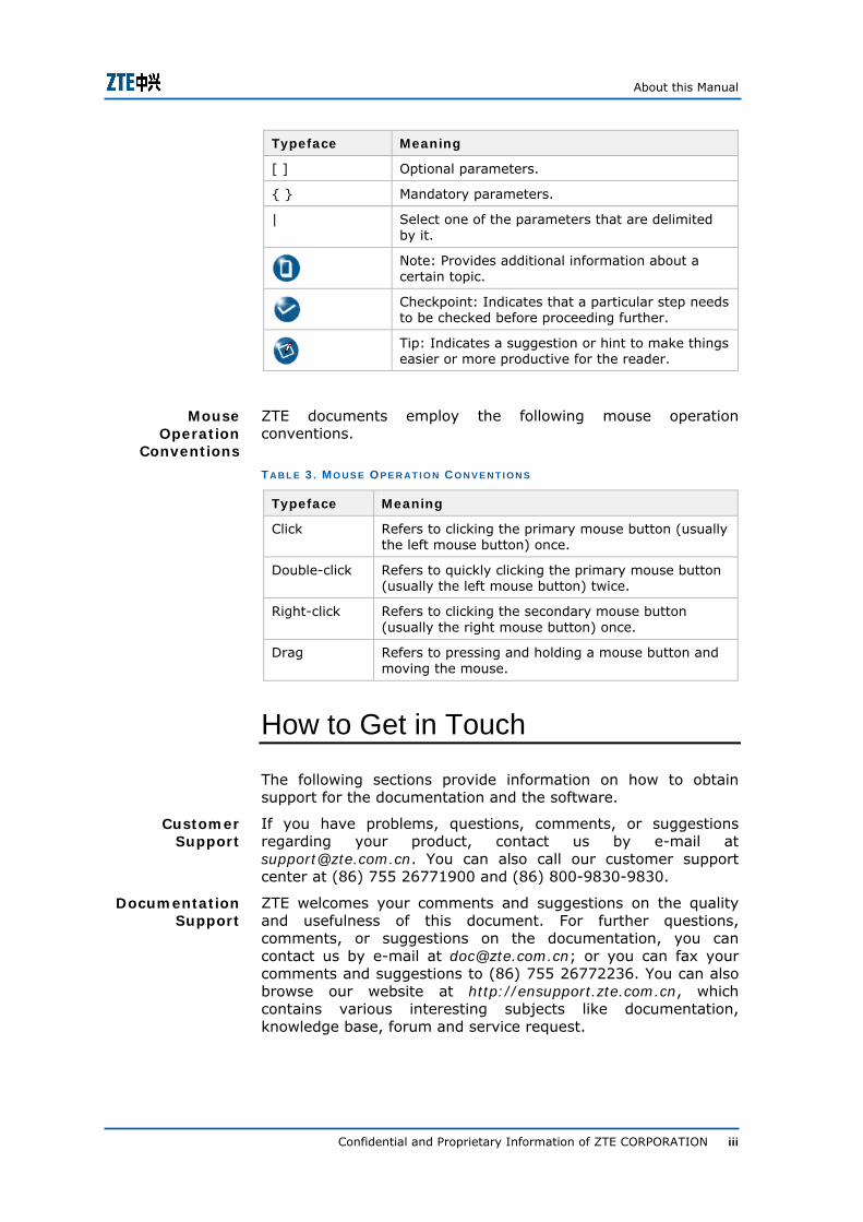
Typeface Meaning
[ ] Optional parameters.
{ } Mandatory parameters.
| Select one of the parameters that are delimited by it.
Note: Provides additional information about a certain topic.
Checkpoint: Indicates that a particular step needs to be checked before proceeding further.
Tip: Indicates a suggestion or hint to make things easier or more productive for the reader.
ZTE documents employ the following mouse operation conventions.
T AB L E 3 . M O U S E OP E R AT I O N C O N V E N T I O N S
Typeface Meaning
Click Refers to clicking the primary mouse button (usually the left mouse button) once.
Double-click Refers to quickly clicking the primary mouse button (usually the left mouse button) twice.
Right-click Refers to clicking the secondary mouse button (usually the right mouse button) once.
Drag Refers to pressing and holding a mouse button and moving the mouse.
How to Get in Touch
The following sections provide information on how to obtain support for the documentation and the software.
If you have problems, questions, comments, or suggestions regarding your product, contact us by e-mail at [email protected]. You can also call our customer support center at (86) 755 26771900 and (86) 800-9830-9830.
ZTE welcomes your comments and suggestions on the quality and usefulness of this document. For further questions, comments, or suggestions on the documentation, you can contact us by e-mail at [email protected]; or you can fax your comments and suggestions to (86) 755 26772236. You can also browse our website at http://ensupport.zte.com.cn, which contains various interesting subjects like documentation, knowledge base, forum and service request.
Mouse Operation
Conventions
Customer Support
Documentation Support

ZXMP S325 (V2.00) Operation Instructions
iv Confidential and Proprietary Information of ZTE CORPORATION
This page is intentionally blank.
Confidential and Proprietary Information of ZTE CORPORATION 5
C h a p t e r 1
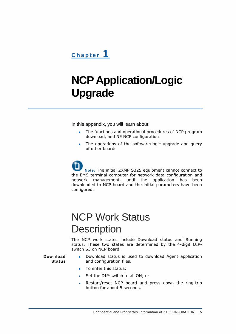
NCP Application/Logic Upgrade
In this appendix, you will learn about: The functions and operational procedures of NCP program
download, and NE NCP configuration
The operations of the software/logic upgrade and query of other boards
Note: The initial ZXMP S325 equipment cannot connect to the EMS terminal computer for network data configuration and network management, until the application has been downloaded to NCP board and the initial parameters have been configured.
NCP Work Status Description The NCP work states include Download status and Running status. These two states are determined by the 4-digit DIP-switch S3 on NCP board.
Download status is used to download Agent application and configuration files.
To enter this status:
Set the DIP-switch to all ON; or
Restart/reset NCP board and press down the ring-trip button for about 5 seconds.
Download Status

ZXMP S325 (V2.00) Operation Instructions
6 Confidential and Proprietary Information of ZTE CORPORATION
The NE IP address is obliged to be 192.192.192.11 under this status.
Running status is used to start the application of NCP board, so that the NCP board can start working normally.
To enter this status, set the DIP-switch to not all ON and not all OFF.
Running Status

Chapter 1 - NCP Application/Logic Upgrade
Confidential and Proprietary Information of ZTE CORPORATION 7
Local Upgrade Local upgrade refers to the procedure of upgrading application/logic when NCP board is in the Download state. This method is not recommended in practice.
Local Upgrade Flowchart
Figure 1 illustrates the local upgrade flow chart.
F I G U R E 1 . LO C A L U P G R AD E FL O W C H AR T
Begin
Prepare for upgrade
Download theapplication/logic
Upgrade theapplication/logic
Verify theapplication/logic
Use telnetmethod
Use ftpmethod
End
Download the database
Verify theapplication/logic version
in the EMS
Performed inthe EMS
Clear the database
Flowchart

ZXMP S325 (V2.00) Operation Instructions
8 Confidential and Proprietary Information of ZTE CORPORATION
Upgrade Preparations
Figure 2 illustrates the preparations for local upgrade.
F I G U R E 2 . P R E P AR AT I O N S F O R LO C AL U P G R AD E OP E R A T I O N S
Begin
Confirm the BOOTROM chip is correct and the CF
card is ready
Set the DIP switch of NCP board to all ON; or under the normal running state,
restart/reset NCP board and press down the ring-trip switch for long time
Set the EMS IP address
Check the equipment status and the network
connection statusping 192.192.192.11
Is it the first time to use the CF card?
Format the CF card
Disconnected
Connected
Yes
No
Confirm the network cable between EMS and the Qx interface of NCP board is
correctly connected
Is it necessary to reconfigure the NE information?
Clear the NCP database
Yes
No
End
Configure the NE information
Reset the NCP board
Reset the NCP board
Flowchart
Chapter 1 - NCP Application/Logic Upgrade
Confidential and Proprietary Information of ZTE CORPORATION 9
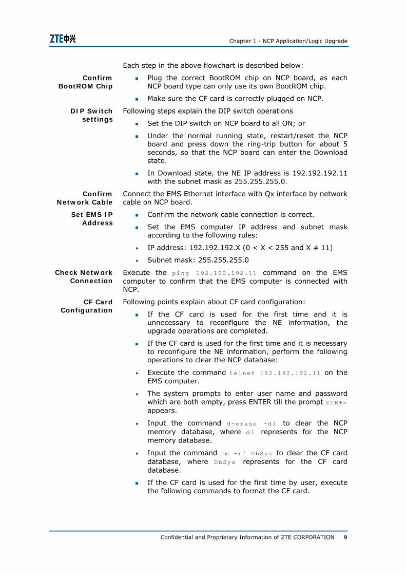
Each step in the above flowchart is described below:
Plug the correct BootROM chip on NCP board, as each NCP board type can only use its own BootROM chip.
Make sure the CF card is correctly plugged on NCP.
Following steps explain the DIP switch operations
Set the DIP switch on NCP board to all ON; or
Under the normal running state, restart/reset the NCP board and press down the ring-trip button for about 5 seconds, so that the NCP board can enter the Download state.
In Download state, the NE IP address is 192.192.192.11 with the subnet mask as 255.255.255.0.
Connect the EMS Ethernet interface with Qx interface by network cable on NCP board.
Confirm the network cable connection is correct.
Set the EMS computer IP address and subnet mask according to the following rules:
IP address: 192.192.192.X (0 < X < 255 and X ≠ 11)
Subnet mask: 255.255.255.0
Execute the ping 192.192.192.11 command on the EMS computer to confirm that the EMS computer is connected with NCP.
Following points explain about CF card configuration:
If the CF card is used for the first time and it is unnecessary to reconfigure the NE information, the upgrade operations are completed.
If the CF card is used for the first time and it is necessary to reconfigure the NE information, perform the following operations to clear the NCP database:
Execute the command telnet 192.192.192.11 on the EMS computer.
The system prompts to enter user name and password which are both empty, press ENTER till the prompt ZTE+> appears.
Input the command d-erase –d1 to clear the NCP memory database, where d1 represents for the NCP memory database.
Input the command rm –rf DbSys to clear the CF card database, where DbSys represents for the CF card database.
If the CF card is used for the first time by user, execute the following commands to format the CF card.
Confirm BootROM Chip
DIP Switch settings
Confirm Network Cable
Set EMS IP Address
Check Network Connection
CF Card Configuration

ZXMP S325 (V2.00) Operation Instructions
10 Confidential and Proprietary Information of ZTE CORPORATION
Execute the command telnet 192.192.192.11 in the EMS computer.
The system prompts to enter user name and password which are both empty, press ENTER till the prompt ZTE+> appears.
Input the command format under the prompt ZTE+> to format the CF card.
Caution: The CF card contains critical configurations, which includes NE IP address, MAC address, subnet mask, database information, and board configuration.
User must be careful to use the format operation as it clears all the data on CF card.
Input the command d-reboot to reset the NCP board. If the reset is successful, the system will prompt “The connection with the host is lost”.
Following steps help user to configure the NE IP address, subnet mask, and MAC address.
1. Input the command telnet 192.192.192.11 on the EMS computer. When the system prompts to enter user name and password which are both empty, press ENTER till the prompt ZTE+> appears.
2. Input the command d-cfgnet under the prompt ZTE+> to configure the NE IP address, subnet mask, and MAC address.
Table 4 illustrates each item’s input.
T AB L E 4 . C O N F I G U R AT I O N D E T AI L S
Parameter Name Input Remarks
IP Address Input the IP address of the NE. It is mandatory.
Subnet Mask Input the subnet mask of the NE. It is mandatory.
MAC Address Input the physical address of the NE.
It is mandatory, but must be unique for each NE.
Warning: Each parameter must be entered. Press ENTER directly if there is no modification. Do not quit the procedure in middle as NCP board will stay in the infinite waiting state.
3. Once the configuration is completed, the system will display the newly configured NE address.
4. Save the configuration according to system prompt.
Input the command d-reboot to reset the NCP board. Then the NE IP address will take effect. All the preparations for local upgrade are completed.
Resetting NCP Card
NE IP Address Configuration
Reset NCP Board

Chapter 1 - NCP Application/Logic Upgrade
Confidential and Proprietary Information of ZTE CORPORATION 11
Downloading Application/Logic
To download the application or logic of NCP board.
1. Execute the command ftp 192.192.192.11.When the system prompts to input the username and password which are both empty, press ENTER until the prompt ftp> appears.
2. Execute the following commands under the ftp> prompt, to deliver the application/logic to the NCP board.
i. ftp> bin
//Set the file transfer mode to binary mode.
ii. ftp> put file name of the application/logic
//Deliver the board application/logic.
iii. ftp> ls
//Check if the file download succeeds. If not, re-download the file.
iv. ftp> bye
//Exit ftp connection.
Caution: The NCP board application must be named as “NCP***.BIN”, and the logic must be named as “NCP***.FPZ” or “NCP***.RBF”. Otherwise the automatic download cannot be implemented. The file extension name can be either lower-case or upper-case.
END OF STEPS.
Upgrading Application/Logic
To upgrade the application or logic on CF card to the application or logic area.
1. Execute the command telnet 192.192.192.11.
2. When the system prompts to input the username and password which are both empty, press ENTER directly until the prompt ZTE+> appears.
Purpose
Steps
Purpose
Steps
ZXMP S325 (V2.00) Operation Instructions
12 Confidential and Proprietary Information of ZTE CORPORATION
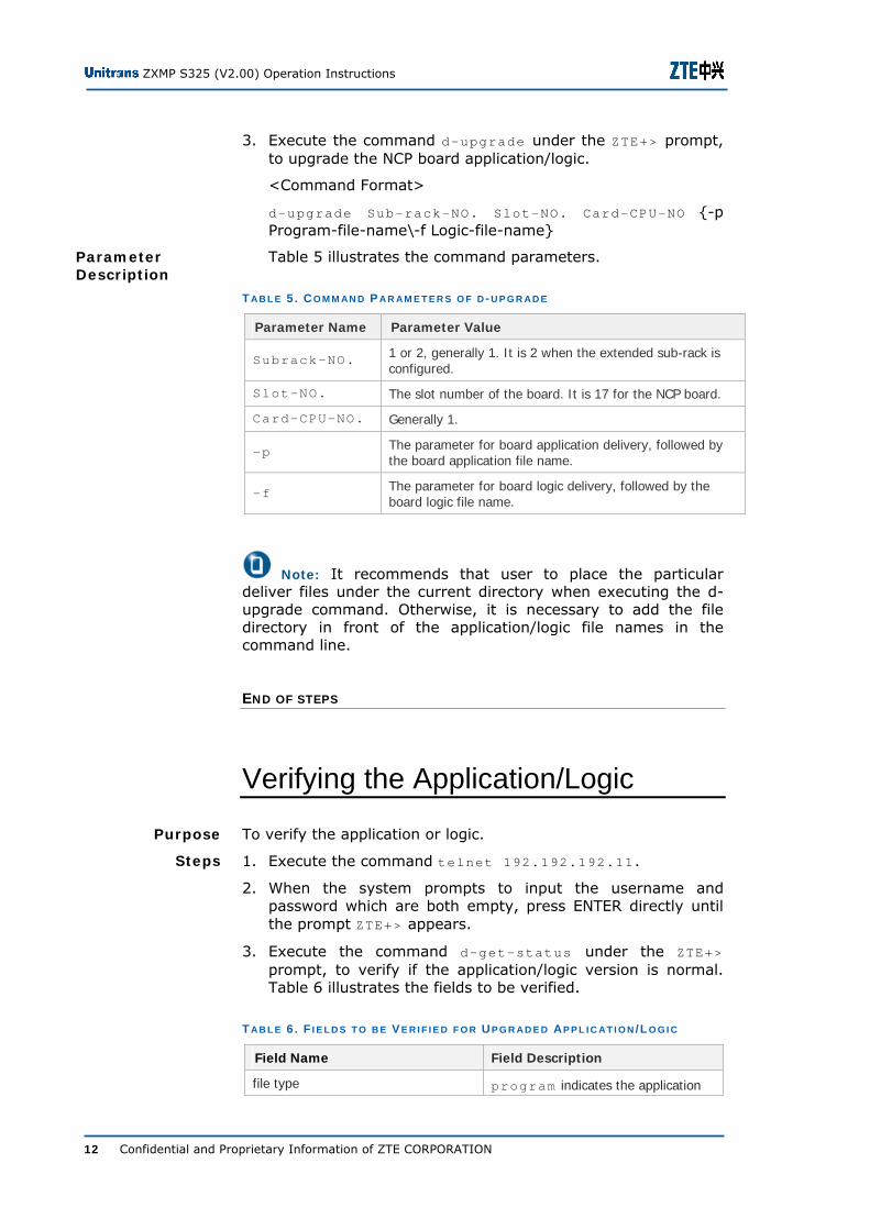
3. Execute the command d-upgrade under the ZTE+> prompt, to upgrade the NCP board application/logic.
<Command Format>
d-upgrade Sub-rack-NO. Slot-NO. Card-CPU-NO {-p Program-file-name\-f Logic-file-name}
Table 5 illustrates the command parameters.
T AB L E 5 . C O M M AN D P A R AM E T E R S O F D -U P G R A D E
Parameter Name Parameter Value
Subrack-NO. 1 or 2, generally 1. It is 2 when the extended sub-rack is configured.
Slot-NO. The slot number of the board. It is 17 for the NCP board.
Card-CPU-NO. Generally 1.
-p The parameter for board application delivery, followed by the board application file name.
-f The parameter for board logic delivery, followed by the board logic file name.
Note: It recommends that user to place the particular deliver files under the current directory when executing the d-upgrade command. Otherwise, it is necessary to add the file directory in front of the application/logic file names in the command line.
END OF STEPS
Verifying the Application/Logic
To verify the application or logic.
1. Execute the command telnet 192.192.192.11.
2. When the system prompts to input the username and password which are both empty, press ENTER directly until the prompt ZTE+> appears.
3. Execute the command d-get-status under the ZTE+> prompt, to verify if the application/logic version is normal. Table 6 illustrates the fields to be verified.
T AB L E 6 . F I E L D S T O B E V E R I F I E D F O R U P G R AD E D AP P L I C AT I O N /LO G I C
Field Name Field Description
file type program indicates the application
Parameter Description
Purpose
Steps

Chapter 1 - NCP Application/Logic Upgrade
Confidential and Proprietary Information of ZTE CORPORATION 13
Field Name Field Description
area
download date File downloaded time
download version File version downloaded
try-run type reserved indicates that this parameter is reserved
status master indicates the master status
upgrade database NO indicates the database is not upgraded
start address 0x0A000000 indicates the initial address of the program
file length The size of the downloaded file
try-run elapsed time reserved indicates that this parameter is reserved
try-run remained time reserved indicates that this parameter is reserved
Note: If the version is abnormal, it is necessary to re-perform the operations described in the Downloading Application/Logic and Upgrading Application/Logic sections until the version queried is normal.
The format of d-get-status command is:
d-get-status Subrack-NO. Slot-NO. Card-CPU-NO.
The command parameters are described in Table 7.
T AB L E 7 . C O M M AN D P AR AM E T E R S
Parameter Name
Parameter Value
Sub-rack-No. 1 or 2, generally 1.
Slot-No. The slot number of the board. It is an integer ranging from 1 to 19. It is 17 for the NCP board.
Card-CPU-No. Integer ranging from 1 to 3, generally 1.
END OF STEPS
Related Information

ZXMP S325 (V2.00) Operation Instructions
14 Confidential and Proprietary Information of ZTE CORPORATION
Clearing Database
To clear the NCP database.
The NCP database was not cleared during upgrade preparation.
1. Execute the command telnet 192.192.192.11 on EMS computer.
2. The system prompts to enter the user name and password which are both empty. Press ENTER directly.
3. Input the command d-erase –d1 to clear the NCP memory database.
4. Input the command rm –rf DbSys to clear the CF card database.
END OF STEPS
Downloading Database
To download NCP database.
1. Set the DIP switch of NCP board to non full ON and non full OFF, and then reset the NCP board. The NCP board enters into the Running state.
Note: If the Download state is entered by restarting/resetting NCP board and pressing down the ring-trip button for 5 seconds, unplugging the NCP board and re-inserting it into the slot can enable the NCP board to enter the Running state.
2. Set the EMS computer IP address to be within the same network section as the NE IP address.
3. Execute the command ping NE-IP to confirm if the NE can be pinged through.
4. Select the particular NE to upgrade in the EMS client operation window, and click the menu System->NCP Data Management->DB Download to download all the databases via the EMS software.
Note: It is unnecessary to download the database when upgrading the logic.
END OF STEPS
Purpose
Prerequisite
Steps
Purpose
Steps

Chapter 1 - NCP Application/Logic Upgrade
Confidential and Proprietary Information of ZTE CORPORATION 15
Verifying Application/Logic Version in EMS
To verify the application/logic version in EMS.
1. Double-click the NE in ZXONM E300 EMS, which is upgraded to open the Card Management dialog box.
2. Right-click the NCP board to query its version. The shortcut menu will pop up. Select the Card Special Version.
3. The Card Special Version dialog box display the application/logic version of the queried NCP board. If the information displayed is consistent with the downloaded application/logic version, it indicates that the newly downloaded application/logic is running normally.
END OF STEPS
Purpose
Steps
ZXMP S325 (V2.00) Operation Instructions
16 Confidential and Proprietary Information of ZTE CORPORATION
Remote Upgrade Remote Upgrade Flowchart
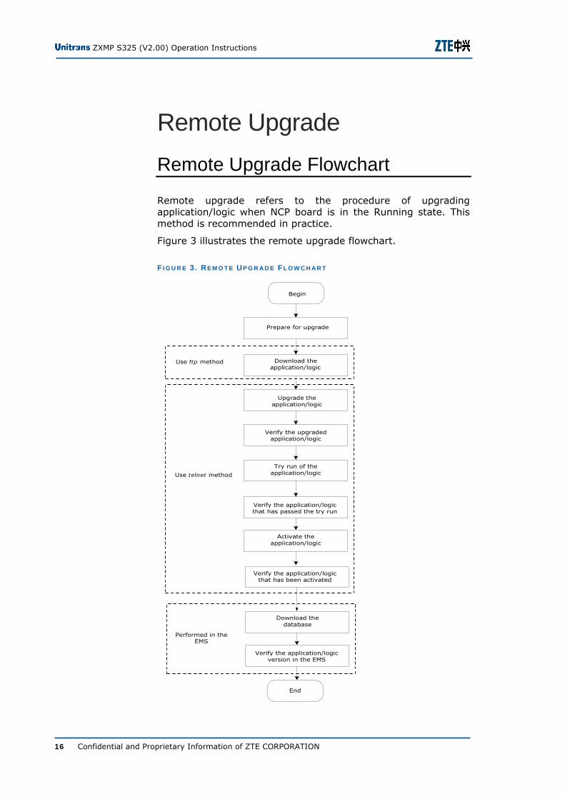
Remote upgrade refers to the procedure of upgrading application/logic when NCP board is in the Running state. This method is recommended in practice.
Figure 3 illustrates the remote upgrade flowchart.
F I G U R E 3 . RE M O T E U P G R AD E FL O W C H AR T
Use telnet method
Performed in theEMS
Begin
End
Prepare for upgrade
Download theapplication/logic
Upgrade theapplication/logic
Try run of theapplication/logic
Verify the upgradedapplication/logic
Activate theapplication/logic
Download thedatabase
Verify the application/logicversion in the EMS
Verify the application/logicthat has passed the try run
Verify the application/logicthat has been activated
Use ftp method
Chapter 1 - NCP Application/Logic Upgrade
Confidential and Proprietary Information of ZTE CORPORATION 17
Preparing for Upgrade To prepare for remote upgrade
1. Execute the ping NE-IP command at the EMS terminal. Confirm that the EMS terminal communicates normally with the NE, and that the NE ECC upgraded smoothly.
2. Confirm that the NCP program version comply with the current EMS version. Ensure the versions validity and consistency.
END OF STEPS
Downloading the Application/Logic
To download the application or logic.
1. Execute the command ftp NE-IP under the directory which contains the application and logic.
2. Input the user name as zte and password as ecc and press ENTER. Then the prompt ftp> will appear.
3. Execute the following commands under the ftp> prompt, to download the application/logic.
i . ftp> bin
//Set the file transfer mode to binary mode.
ii. ftp> put file name of the application/logic //Download the board application/logic. If the prompt ftp> appears again, it indicates that the file transfer is completed.
4. Execute the command ftp>ls-l to check if the size of downloaded file is consistent with the local file. If not, re-download the file.
5. Execute the command ftp> bye to exit ftp connection.
Caution: The board application and logic must be transferred to NCP board using the binary mode.
END OF STEPS
Purpose
Steps
Purpose
Steps
ZXMP S325 (V2.00) Operation Instructions
18 Confidential and Proprietary Information of ZTE CORPORATION
Upgrading Application/Logic
To upgrade the application or logic to the application area or logic area.
1. Execute the command telnet NE-IP.
2. Input the user name as zte and password as ecc and press ENTER till the prompt ZTE+> appears.
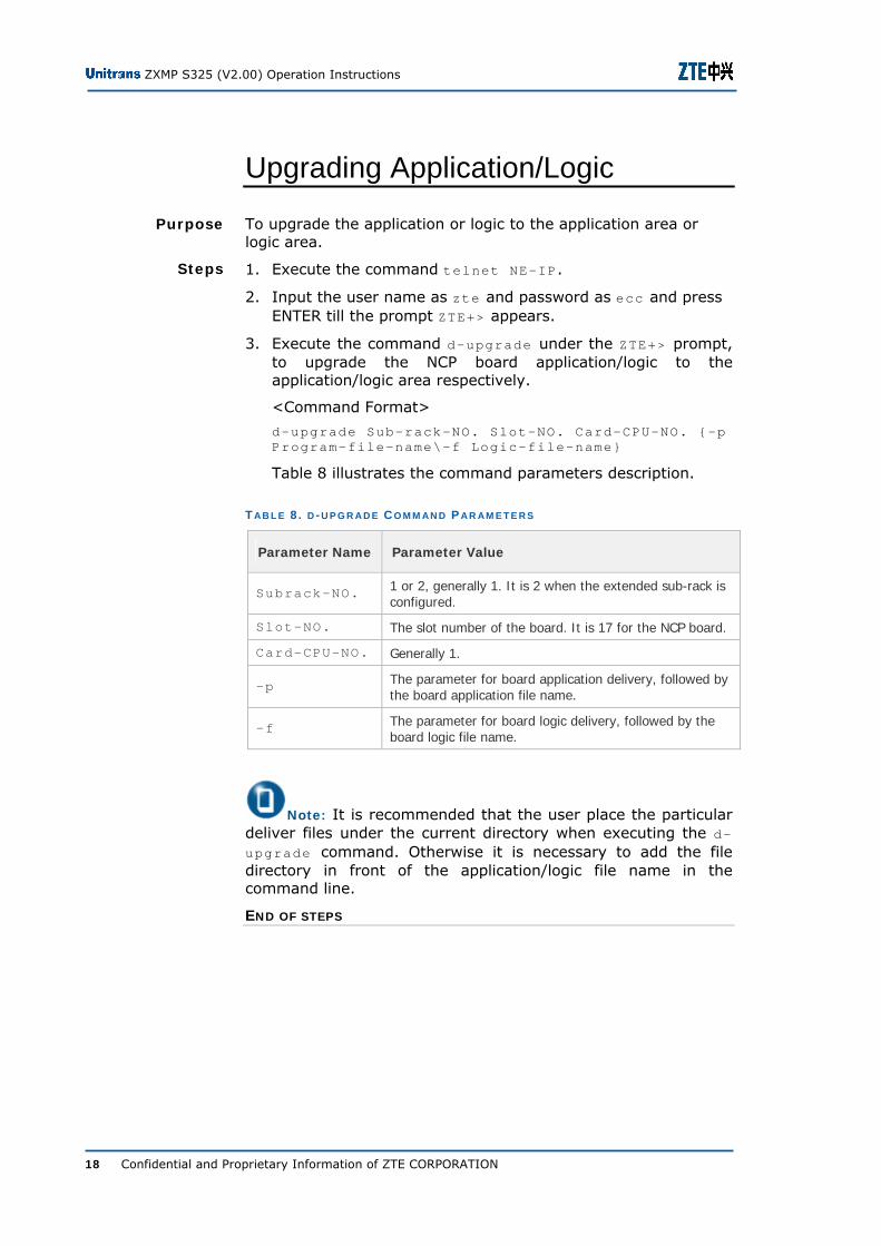
3. Execute the command d-upgrade under the ZTE+> prompt, to upgrade the NCP board application/logic to the application/logic area respectively.
<Command Format>
d-upgrade Sub-rack-NO. Slot-NO. Card-CPU-NO. {-p Program-file-name\-f Logic-file-name}
Table 8 illustrates the command parameters description.
T AB L E 8 . D -U P G R A D E C O M M AN D P AR AM E T E R S
Parameter Name Parameter Value
Subrack-NO. 1 or 2, generally 1. It is 2 when the extended sub-rack is configured.
Slot-NO. The slot number of the board. It is 17 for the NCP board.
Card-CPU-NO. Generally 1.
-p The parameter for board application delivery, followed by the board application file name.
-f The parameter for board logic delivery, followed by the board logic file name.
Note: It is recommended that the user place the particular deliver files under the current directory when executing the d-upgrade command. Otherwise it is necessary to add the file directory in front of the application/logic file name in the command line.
END OF STEPS
Purpose
Steps
Chapter 1 - NCP Application/Logic Upgrade
Confidential and Proprietary Information of ZTE CORPORATION 19
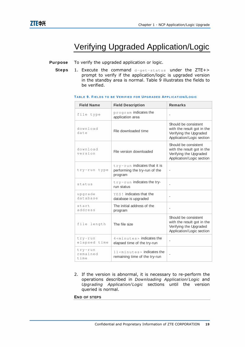
Verifying Upgraded Application/Logic
To verify the upgraded application or logic.
1. Execute the command d-get-status under the ZTE+> prompt to verify if the application/logic is upgraded version in the standby area is normal. Table 9 illustrates the fields to be verified.
T AB L E 9 . F I E L D S T O B E V E R I F I E D F O R U P G R AD E D AP P L I C AT I O N /LO G I C
Field Name Field Description Remarks
file type program indicates the application area
-
download date File downloaded time
Should be consistent with the result got in the Verifying the Upgraded Application/Logic section
download version File version downloaded
Should be consistent with the result got in the Verifying the Upgraded Application/Logic section
try-run typetry-run indicates that it is performing the try-run of the program
-
status try-run indicates the try-run status
-
upgrade database
YES! indicates that the database is upgraded
-
start address
The initial address of the program -
file length The file size
Should be consistent with the result got in the Verifying the Upgraded Application/Logic section
try-run elapsed time
4<minutes> indicates the elapsed time of the try-run
-
try-run remained time
11<minutes> indicates the remaining time of the try-run
-
2. If the version is abnormal, it is necessary to re-perform the operations described in Downloading Application/Logic and Upgrading Application/Logic sections until the version queried is normal.
END OF STEPS
Purpose
Steps
ZXMP S325 (V2.00) Operation Instructions
20 Confidential and Proprietary Information of ZTE CORPORATION
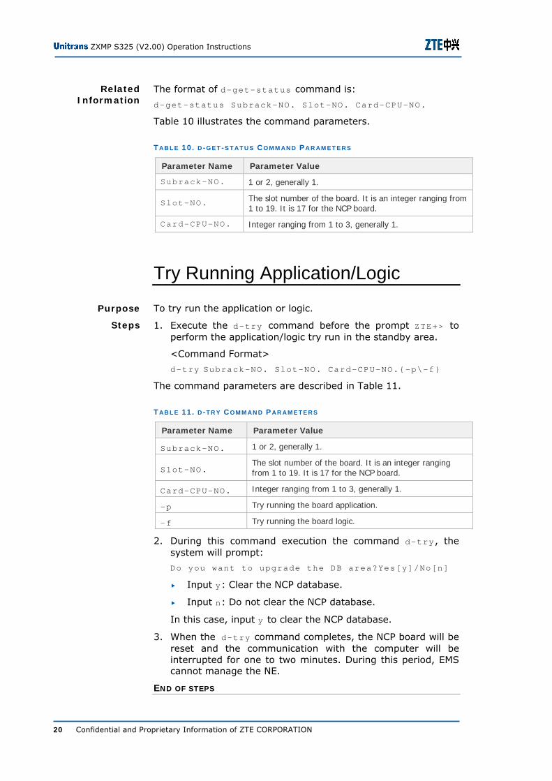
The format of d-get-status command is:
d-get-status Subrack-NO. Slot-NO. Card-CPU-NO.
Table 10 illustrates the command parameters.
T AB L E 10 . D -G E T -S T AT U S C O M M AN D P A R AM E T E R S
Parameter Name Parameter Value
Subrack-NO. 1 or 2, generally 1.
Slot-NO. The slot number of the board. It is an integer ranging from 1 to 19. It is 17 for the NCP board.
Card-CPU-NO. Integer ranging from 1 to 3, generally 1.
Try Running Application/Logic
To try run the application or logic.
1. Execute the d-try command before the prompt ZTE+> to perform the application/logic try run in the standby area.
<Command Format>
d-try Subrack-NO. Slot-NO. Card-CPU-NO.{-p\-f}
The command parameters are described in Table 11.
T AB L E 11 . D -T R Y C O M M AN D P AR AM E T E R S
Parameter Name Parameter Value
Subrack-NO. 1 or 2, generally 1.
Slot-NO. The slot number of the board. It is an integer ranging from 1 to 19. It is 17 for the NCP board.
Card-CPU-NO. Integer ranging from 1 to 3, generally 1.
-p Try running the board application.
-f Try running the board logic.
2. During this command execution the command d-try, the system will prompt:
Do you want to upgrade the DB area?Yes[y]/No[n]
Input y: Clear the NCP database.
Input n: Do not clear the NCP database.
In this case, input y to clear the NCP database.
3. When the d-try command completes, the NCP board will be reset and the communication with the computer will be interrupted for one to two minutes. During this period, EMS cannot manage the NE.
END OF STEPS
Related Information
Purpose
Steps

Chapter 1 - NCP Application/Logic Upgrade
Confidential and Proprietary Information of ZTE CORPORATION 21
Verifying Application/Logic after Try Run
To verify the application or logic that has passed try run.
1. Execute the telnet NE-IP command on the EMS computer.
2. Input the user name as zte and password as ecc according to the system prompts. Press ENTER till the prompt ZTE+> appears.
3. Execute the command d-get-status to check the version of application/logic that has passed try run in the original standby area. Table 12 lists the fields need to be verified in the original standby area.
T AB L E 12 . F I E L D S T O B E V E R I F I E D I N T H E OR I G I N AL S T A N D B Y AR E A
Field Name Field Description Remarks
file type program indicates the application area
-
download date File downloaded time
Should be consistent with the result got in the Verifying the Upgraded Application/Logic section
download version File version downloaded
Should be consistent with the result got in the Verifying the Upgraded Application/Logic section
try-run type try-run indicates that it is performing the try-run of the program
-
Status try-run indicates the try-run status
-
upgrade database
YES! indicates that the database is upgraded
-
start address
The initial address of the program -
file length The file size
Should be consistent with the result got in the Verifying the Upgraded Application/Logic section
try-run elapsed time
4<minutes> indicates the elapsed time of the try-run
-
try-run remained time
11<minutes> indicates the remaining time of the try-run
-
Purpose
Steps
ZXMP S325 (V2.00) Operation Instructions
22 Confidential and Proprietary Information of ZTE CORPORATION
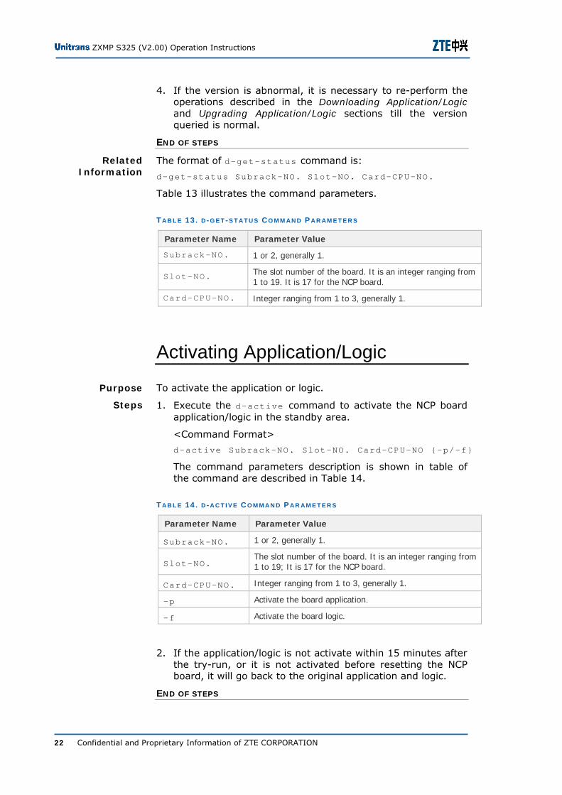
4. If the version is abnormal, it is necessary to re-perform the operations described in the Downloading Application/Logic and Upgrading Application/Logic sections till the version queried is normal.
END OF STEPS
The format of d-get-status command is:
d-get-status Subrack-NO. Slot-NO. Card-CPU-NO.
Table 13 illustrates the command parameters.
T AB L E 13 . D -G E T -S T AT U S C O M M AN D P A R AM E T E R S
Parameter Name Parameter Value
Subrack-NO. 1 or 2, generally 1.
Slot-NO. The slot number of the board. It is an integer ranging from 1 to 19. It is 17 for the NCP board.
Card-CPU-NO. Integer ranging from 1 to 3, generally 1.
Activating Application/Logic
To activate the application or logic.
1. Execute the d-active command to activate the NCP board application/logic in the standby area.
<Command Format>
d-active Subrack-NO. Slot-NO. Card-CPU-NO {-p/-f}
The command parameters description is shown in table of the command are described in Table 14.
T AB L E 14 . D -A C T I V E C O M M AN D P AR AM E T E R S
Parameter Name Parameter Value
Subrack-NO. 1 or 2, generally 1.
Slot-NO. The slot number of the board. It is an integer ranging from 1 to 19; It is 17 for the NCP board.
Card-CPU-NO. Integer ranging from 1 to 3, generally 1.
-p Activate the board application.
-f Activate the board logic.
2. If the application/logic is not activate within 15 minutes after the try-run, or it is not activated before resetting the NCP board, it will go back to the original application and logic.
END OF STEPS
Related Information
Purpose
Steps
Chapter 1 - NCP Application/Logic Upgrade
Confidential and Proprietary Information of ZTE CORPORATION 23
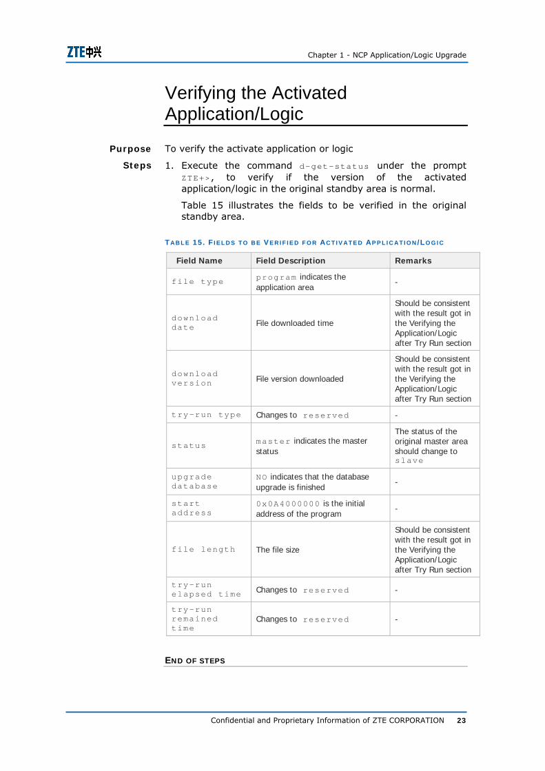
Verifying the Activated Application/Logic
To verify the activate application or logic
1. Execute the command d-get-status under the prompt ZTE+>, to verify if the version of the activated application/logic in the original standby area is normal.
Table 15 illustrates the fields to be verified in the original standby area.
T AB L E 15 . F I E L D S T O B E V E R I F I E D F O R AC T I V AT E D AP P L I C AT I O N /LO G I C
Field Name Field Description Remarks
file type program indicates the application area
-
download date File downloaded time
Should be consistent with the result got in the Verifying the Application/Logic after Try Run section
download version File version downloaded
Should be consistent with the result got in the Verifying the Application/Logic after Try Run section
try-run type Changes to reserved -
status master indicates the master status
The status of the original master area should change to slave
upgrade database
NO indicates that the database upgrade is finished
-
start address
0x0A4000000 is the initial address of the program
-
file length The file size
Should be consistent with the result got in the Verifying the Application/Logic after Try Run section
try-run elapsed time Changes to reserved -
try-run remained time
Changes to reserved -
END OF STEPS
Purpose
Steps

ZXMP S325 (V2.00) Operation Instructions
24 Confidential and Proprietary Information of ZTE CORPORATION
The format of d-get-status command is:
d-get-status Subrack-NO. Slot-NO. Card-CPU-NO.
Table 16 illustrates the command parameters.
T AB L E 16 . D -G E T -S T AT U S C O M M AN D P A R AM E T E R S
Parameter Name Parameter Value
Subrack-NO. 1 or 2, generally 1.
Slot-NO. The slot number of the board. It is an integer ranging from 1 to 19. It is 17 for the NCP board.
Card-CPU-NO. Integer ranging from 1 to 3, generally 1.
Downloading Database
To download NCP database.
Before downloading the database, make sure to clear the original database.
If the database was not cleared during the Try Running Application/Logic phase, execute the telnet NE-IP command to log into NCP board and then execute the a-clr-ncpdb command to clear the database.
1. Select a particular NE to upgrade.
2. Click the System->NCP data Management->DB Download menu.
3. Download all the NCP databases in the dialog box.
Note: It is unnecessary to download database when upgrading NCP logic.
Verifying Application/Logic Version in EMS
To verify the application version or logic version in EMS.
1. Double-click the NE which is upgraded in ZXONM E300 EMS, to open the Card Management dialog.
2. Right click the NCP board to query the version to display the shortcut menu. Select the Card Special Version menu.
3. The Card Special Version dialog box displays the application and logic version.
Related Information
Purpose
Prerequisite
Steps
Purpose
Steps

Chapter 1 - NCP Application/Logic Upgrade
Confidential and Proprietary Information of ZTE CORPORATION 25
4. If the information displayed is consistent with the downloaded application/logic, it indicates that the newly downloaded application/logic is running normally.
END OF STEPS

ZXMP S325 (V2.00) Operation Instructions
26 Confidential and Proprietary Information of ZTE CORPORATION
This page is intentionally blank.
Confidential and Proprietary Information of ZTE CORPORATION 27
C h a p t e r 2
Equipment Power-ON/OFF
Powering ON Equipment To power-ON ZXMP S330 equipment during routine maintenance.
1. Make sure the hardware installation and cable layout are correct.
2. Make sure the equipment input power satisfies the requirements, and there is no short circuit inside the equipment.
3. Turn ON the power supply loop switch.
4. Set the air switch of power distributor box to “ON” status to power ON the equipment.
5. Observe if the running status of fan and boards are normal.
END OF STEPS
Purpose
Steps
ZXMP S325 (V2.00) Operation Instructions
28 Confidential and Proprietary Information of ZTE CORPORATION
Powering OFF Equipment To power OFF ZXMP S330 equipment during routine maintenance if needed.
1. Set the air switch of power distributor box to “OFF” status to shut off the cabinet.
2. Turn OFF power supply loop switch to power OFF the equipment.
Warning: Powering off the equipment will result in interruption of all services in the NE. Since the transmission equipment is very important in the network, power-off operation should be avoided once the equipment is in service to guarantee continuous traffic transmission.
END OF STEPS
Purpose
Steps

Confidential and Proprietary Information of ZTE CORPORATION 29
C h a p t e r 3
Data Backup/Restore
Backing up Data In the ZXONM E300 EMS software, data backup is primarily used to copy and save the data of the Manager database. In network operation and maintenance, it is necessary to back up the system data often so that the network data is quickly recoverable in case of network fault and EMS data loss.
1. Select the menu item System -> System Data Management -> DB Backup or Restore in the main view of the ZXONM E300 EMS client operation window to access the Database Backup/Restore dialog box. The default page is the DB Backup/Restore page.
2. Select the Backup radio button in the Backup/Restore area.
3. Enter the backup folder name in the Backup Name text box.
4. Select the Backup/Restore Directory check box to activate the text box below it.
5. Click the button after the text box to pop up the Select Directory dialog box. Then select a directory in the directory list and click the Apply button.
Tip: You can also manually enter the path in the Backup/Restore Directory text box directly when backing up the data in customized folder. Be sure that the “/” should be used as the separator.
6. Click the Backup DB button to start the backup.
Purpose
Steps

ZXMP S325 (V2.00) Operation Instructions
30 Confidential and Proprietary Information of ZTE CORPORATION
Note: It is recommended to save the backup data in a mobile storage device lest backup loss in the case of hard disk fault of the EMS host.
Upon successful data backup, there should be a folder with the same name as the backup folder in the directory where the backup folder is located.
If the backup file does not exist, back up the data again.
Result
Troubleshooting
Chapter 3 - Data Backup/Restore
Confidential and Proprietary Information of ZTE CORPORATION 31
Restoring Data In the case of network fault or EMS data loss, use the ZXONM E300 EMS software to recover the data that is backed up at the EMS database side. The recovery implemented by the ZXONM E300 covers all the current data.
1. Select the menu item System -> System Data Management -> DB Backup or Restore in the main view of the ZXONM E300 client operation window to access the Database Backup/Restore dialog box. The default page is the DB Backup/Restore page.
2. Select the Restore radio button in the Backup/Restore area.
3. Select the Backup/Restore Directory check box.
4. Click the button after the text box to pop up the Select Directory dialog box. Then in the directory list, select the directory where the data to be restored are located. And click the Apply button.
Tip: You can also manually enter the path in the Backup/Restore Directory text box directly. Be sure that the “/” should be used as the separator.
5. Click the Query Backup button in the Database Backup/Restore dialog box, and the backup folder name will be listed in the Backup Directory list box at the left of the dialog box.
6. Click the backup folder in the list box, and it will be displayed in the Backup Name text box.
7. Click the Restore DB button to start restoring the data.
Upon successful data restore, the Login Management dialog box will pop up, as shown in Figure 4.
Purpose
Steps
Result

ZXMP S325 (V2.00) Operation Instructions
32 Confidential and Proprietary Information of ZTE CORPORATION
F I G U R E 4 . LO G I N M AN AG E M E N T D I AL O G B O X
In the Manager list box, select the server in which the database restore has been implemented. Enter the correct login name and password and click the Log In button to enter the client operation window. The data are the same as the original backup data.
Note: To avoid database conflict, the Manager will forbid the database operation during the database restore procedure, that is, no other operation is allowed on the database during the database restore.
If data cannot be restored because that the original backup data version is higher than current EMS version, upgrade the current EMS to a proper higher version.
Troubleshooting
Confidential and Proprietary Information of ZTE CORPORATION 33
C h a p t e r 4
Board Replacement
Operation Precautions Pay attention to the following precautions when replacing a board:
Since there are many CMOS components in the board, make sure to wear the anti-static wrist strap for connecting human body with the equipment protection ground.
If the equipment is not connected with the protection ground yet, the antistatic wrist strap will not take effect.
There is normally a bag of desiccant in the static-shielding bag, which is used to absorb the moisture of bag keeping it dry from inside.
When the board is carried from a dry place with low temperature to a moist place with high temperature, wait for at least half an hour before unpacking and installation. Otherwise, moisture will condense the board surface, resulting in board damage.
While plugging/unplugging the board, keep it upright and use appropriate force to avoid bending the contact pins.
ZXMP S325 (V2.00) Operation Instructions
34 Confidential and Proprietary Information of ZTE CORPORATION
General Operations of Board Replacement Flowchart
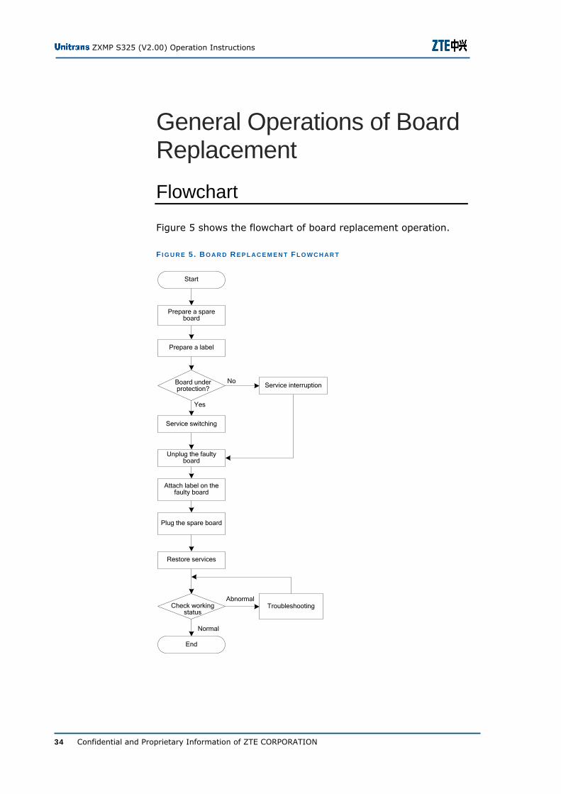
Figure 5 shows the flowchart of board replacement operation.
F I G U R E 5 . BO A R D R E P L A C E M E N T FL O W C H AR T
Start
Unplug the faulty board
Service interruption
Service switching
Plug the spare board
Attach label on the faulty board
No
Yes
Prepare a spare board
Prepare a label
End
TroubleshootingAbnormal
Normal
Restore services
Board under protection?
Check working status

Chapter 4 - Board Replacement
Confidential and Proprietary Information of ZTE CORPORATION 35
Preparing Spare Board
To prepare spare board during board replacement operation.
1. Determine the spare board type according to board to be replaced.
2. Make sure its model is consistent with the board to be replaced.
3. Check whether spare board has any apparent damage, and ensure that it works normally.
4. Make sure board PCB version and software version are compatible with the current NE and EMS.
Note: When the board to be replaced is configured as hot backup mode (Example: SC board and CS board), ensure that the software and hardware versions of both active/standby boards are completely consistent after replacement.
END OF STEPS
Preparing Label
To prepare label for the faulty board during board replacement operation.
The maintenance personnel determine the label size.
Write contents on the label, including the site name, equipment name, fault cause, board name, handling process, the handling person, and time.
END OF STEPS
Service Switching
For a board configured with service protection or backup board, the service function processed by the board should be switched to the standby board when fault occurs, so that the service is not interrupted by board unplugging.
While unplugging the board without service protection or backup, the service function of this board would be interrupted.
Purpose
Steps
Purpose
Steps
ZXMP S325 (V2.00) Operation Instructions
36 Confidential and Proprietary Information of ZTE CORPORATION
Note: Before unplugging the board, inform to the user, and take any possible measure to minimize drawbacks of service interruption.
Unplugging Board
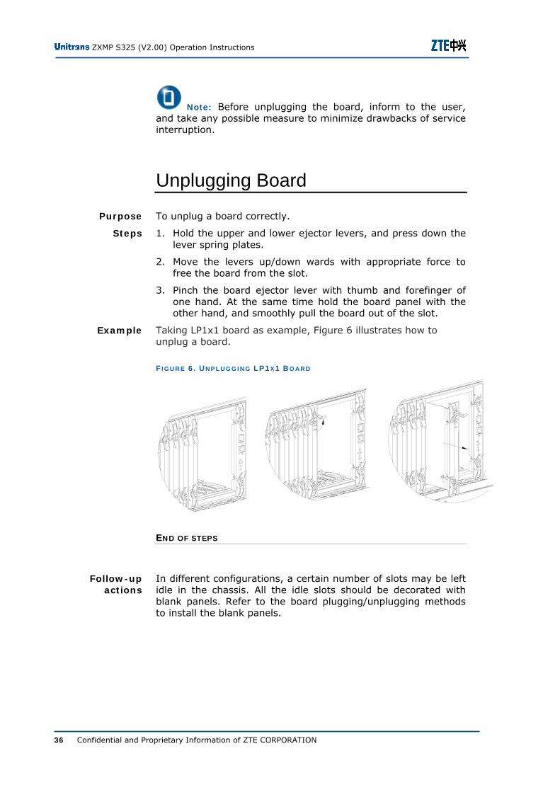
To unplug a board correctly.
1. Hold the upper and lower ejector levers, and press down the lever spring plates.
2. Move the levers up/down wards with appropriate force to free the board from the slot.
3. Pinch the board ejector lever with thumb and forefinger of one hand. At the same time hold the board panel with the other hand, and smoothly pull the board out of the slot.
Taking LP1x1 board as example, Figure 6 illustrates how to unplug a board.
F I G U R E 6 . UN P L U G G I N G LP1 X 1 B O AR D
END OF STEPS
In different configurations, a certain number of slots may be left idle in the chassis. All the idle slots should be decorated with blank panels. Refer to the board plugging/unplugging methods to install the blank panels.
Purpose
Steps
Example
Follow-up actions

Chapter 4 - Board Replacement
Confidential and Proprietary Information of ZTE CORPORATION 37
Labeling Faulty Board
Stick the prepared label on the PCB of the unplugged faulty board.
Plugging Board
To plug a board correctly.
1. Check the slot layout and available slots for boards specified in the design document.
2. Insert the board into the corresponding slot.
3. To plug a board, place the ejector lever at horizontal position by pressing the spring plate of ejector lever.
4. Grasp the upper and lower ejector levers, and push in the board exactly along the guide rail. The board must be kept vertical throughout the process, and apply appropriate force.
5. When the board is about to get into position, clamp the bayonet of ejector lever with front beam of the subrack.
6. Push the ejector lever up/down wards with both hands exerting proper force unless the ejector lever stands upright and produces the locking sound of "clatter".
7. Check the board connector should be fully inserted into the motherboard socket. In this case, the board panel should be in parallel position with outer frame of the board area in the cabinet.
Taking LP1x1 board as example, Figure 7 illustrates how to plug a board.
F I G U R E 7 . P L U G G I N G LP1 X1 B O AR D
END OF STEPS
Purpose
Steps
Example

ZXMP S325 (V2.00) Operation Instructions
38 Confidential and Proprietary Information of ZTE CORPORATION
Restoring Service
To restore service using the newly plugged spare board.
1. Restore service immediately after the spare board is installed.
2. Check the working status of board and equipment.
3. Verify the normal working of both the equipment and the service to ensure successful board replacement.
4. The maintenance person must perform troubleshooting if the equipment or service is not restored properly, till the equipment and service become normal.
END OF STEPS
Purpose
Steps
Chapter 4 - Board Replacement
Confidential and Proprietary Information of ZTE CORPORATION 39
Replacing NCP Board To replace an NCP board.
The NCP board is hot pluggable.
Its replacement does not affect the service but interrupts EMS monitoring temporarily.
The NE needs to be reset after reconfiguring the NCP parameters and data, which in turn will cause service interruption.
1. Prepare the spare board and label as described in Preparing Spare Board and Preparing Label sections.
2. Make sure that the BootROM, NCP board application, and EMS software are compatible with each other.
3. Unplug the NCP board which needs to be replaced and label it.
4. Set DIP-switch of the spare NCP board to full ON state, which makes the NCP board to enter Download state; and plug the board into the subrack.
5. Execute the command ping 192.192.192.11 on the EMS computer to check if it is possible to ping the NE.
6. Download the application and initial parameters via FTP, which are consistent with the original NCP board; and the NCP board can reset automatically if the setting is successful. Refer to Chapter 1 for the NCP program download details.
7. Set the fourth digit of the DIP-switch on the NCP board to OFF, and write the NE configuration data onto the NCP board using EMS software.
8. Check the following for NCP board replacement confirmation:
i. In the Download state, NCP board can ping 192.192.192.11 on the computer.
ii. After replacement, select the NE which has replaced the NCP board in the EMS client operation window.
iii. If the NCP time could be extracted, it indicates the NCP board is successfully replaced.
END OF STEPS
Purpose
Background Information
Steps
ZXMP S325 (V2.00) Operation Instructions
40 Confidential and Proprietary Information of ZTE CORPORATION
Replacing OCS4/OCS16 Board To replace an OCS4 or OCS16 board.
The OCS4/OCS16 board supports hot backup and is hot pluggable.
If the OCS4/OCS16 board is configured to work in hot backup mode, its replacement would not affect service.
Otherwise, its replacement would affect service.
1. Prepare the spare board and label it as described in Preparing Spare Board and Preparing Label sections. The two OCS4/OCS16 boards must have consistent PCB versions.
2. If the OCS4/OCS16 board is configured to work in hot backup mode, switch the system clock to the other OCS4/OCS16 board through EMS. Otherwise, go to step 5.
3. Unplug the OCS4/OCS16 board to be replaced, and attach the label onto it.
4. Plug the spare board, and switch the system clock to the plugged OCS4/OCS16 board.
5. If the OCS4/OCS16 board is not configured to work in hot backup mode, directly unplug the OCS4/OCS16 board, attach the label, and plug the spare board.
6. After replacement, the green indicator NOM on the OCS4/OCS16 board flickers regularly. It indicates that the service has been recovered and the board is successfully replaced.
END OF STEPS
Purpose
Background Information
Steps
Chapter 4 - Board Replacement
Confidential and Proprietary Information of ZTE CORPORATION 41
Replacing Optical Line Board Optical line boards include OL1/4x4 and OL16x1 boards.
The optical line board is hot pluggable.
Its replacement will interrupt the service in case of unprotected networking.
In protected networking, the service will not be interrupted if it is switched to protection mode.
Note: When multiplex section switching ring is configured, the board replacement is too complex to describe. Conduct this kind of board replacement under the guidance of ZTE maintenance engineers.
Replacing Board with No Service Protection
To replace an optical line board that is not configured with service protection.
1. Prepare the spare board and label as described in Preparing Spare Board and Preparing Label sections.
2. Unplug the fiber pigtail connected to the optical interface.
3. Unplug the board to be replaced, attach the label.
4. Plug the spare board, and connect the fiber pigtail.
5. Confirm replacement
After replacement, if the green NOM indicator light on the board blinks slowly and regularly, it indicates that the service is normal and the board replacement is successful.
END OF STEPS
Overview
Purpose
Steps

ZXMP S325 (V2.00) Operation Instructions
42 Confidential and Proprietary Information of ZTE CORPORATION
Replacing Board with Service Protection
To replace an optical line board that is configured with service protection.
1. Prepare the spare board and label as described in Preparing Spare Board and Preparing Label sections.
2. Unplug the fiber pigtail connected to the optical interface, wait until the service switches to the protection path.
3. Unplug the board to be replaced, attach the label.
4. Plug the spare board, and connect the fiber pigtail.
5. Confirm replacement
After replacement, if the green NOM indicator light on the board blinks slowly and regularly, it indicates that the service is normal and the board replacement is successful.
END OF STEPS
Purpose
Steps
Chapter 4 - Board Replacement
Confidential and Proprietary Information of ZTE CORPORATION 43
Replacing Line Processor Line processors include LP1x1, LP1x2, LP4x1, and LP4x2
boards.
The line processor is hot pluggable.
Its replacement will interrupt the service in case of unprotected networking.
In protected networking, the service will not be interrupted if it is switched to protection mode.
Note: When multiplex section switching ring is configured, the board replacement is too complex to describe. Conduct this kind of board replacement under the guidance of ZTE maintenance engineers.
Replacing Board with No Service Protection
To replace a line processor that is not configured with service protection.
1. Prepare the spare board and label as described in Preparing Spare Board and Preparing Label sections.
2. Unplug the fiber pigtail connected to the interface on corresponding interface board.
3. Unplug the board to be replaced, attach the label.
4. Plug the spare board, and connect the fiber pigtail to the interface on corresponding interface board.
5. Confirm replacement
After replacement, if the green RUN indicator light on the board blinks slowly and regularly, it indicates that the service is normal and the board replacement is successful.
END OF STEPS
Overview
Purpose
Steps
ZXMP S325 (V2.00) Operation Instructions
44 Confidential and Proprietary Information of ZTE CORPORATION
Replacing Board with Service Protection
To replace a line processor that is configured with service protection.
1. Prepare the spare board and label as described in Preparing Spare Board and Preparing Label sections.
2. Unplug the fiber pigtail connected to the interface on corresponding interface board, wait until the service switches to the protection path.
3. Unplug the board to be replaced, attach the label.
4. Plug the spare board, and connect the fiber pigtail to the interface on corresponding interface board.
5. Confirm replacement
After replacement, if the green RUN indicator light on the board blinks slowly and regularly, it indicates that the service is normal and the board replacement is successful.
END OF STEPS
Purpose
Steps
Chapter 4 - Board Replacement
Confidential and Proprietary Information of ZTE CORPORATION 45
Replacing Electrical Processor Board To replace an electrical processor board.
Electrical processor boards include EPE1x21, EPT1x21, EPE1B, and EP3x3 boards.
Electrical processor boards are hot pluggable, and their replacement would interrupt service.
1. Prepare the spare board and label as described in Preparing Spare Board and Preparing Label sections.
2. Unplug the board to be replaced, attach the label, and plug the spare board.
3. Confirm replacement
After replacement, the green NOM indicator light on the board flickers slowly and regularly, and the service performance is normal. It indicates that the board replacement is successful.
END OF STEPS
Purpose
Background Information
Steps

ZXMP S325 (V2.00) Operation Instructions
46 Confidential and Proprietary Information of ZTE CORPORATION
Replacing Ethernet Board To replace an SFEx6 board which is an Ethernet board
SFEx6 board is hot pluggable.
Replacing the Ethernet board would interrupt Ethernet service.
1. Prepare the spare board and label as described in Preparing Spare Board and Preparing Label sections.
2. Unplug the board to be replaced, attach the label, and plug the spare board.
3. Confirm replacement
After replacement, the green NOM indicator light on the board flickers slowly and regularly. It indicates that the service performance is normal, and the board replacement is successful.
END OF STEPS
Purpose
Background Information
Steps

Chapter 4 - Board Replacement
Confidential and Proprietary Information of ZTE CORPORATION 47
Replacing ATM Board To replace an AP1x4 board which is an ATM board.
AP1x4 board is hot pluggable.
Replacing the AP1x4 board would interrupt ATM service.
1. Prepare the spare board and label as described in Preparing Spare Board and Preparing Label sections.
2. Unplug the board to be replaced, attach the label.
3. Plug the spare board, and connect the fiber pigtails.
4. Confirm replacement
After replacement, the green NOM indicator light on the AP1x4 board blinks slowly and regularly. It indicates that the service performance is normal, and the board replacement is successful.
END OF STEPS
Purpose
Background Information
Steps

ZXMP S325 (V2.00) Operation Instructions
48 Confidential and Proprietary Information of ZTE CORPORATION
This page is intentionally blank.
Confidential and Proprietary Information of ZTE CORPORATION 49
C h a p t e r 5
Equipment Upgrade
Version Overview To differentiate between new and old, hardware and software, all of them should be labeled with version numbers, including equipment version, EMS software version, board PCB version and software versions of the NCP board and other boards.
Equipment version refers to the ZXMP S325 development version, which is currently V2.00.
EMS software version refers to the EMS software development version.
To query this version, go to the operation window of the EMS software client.
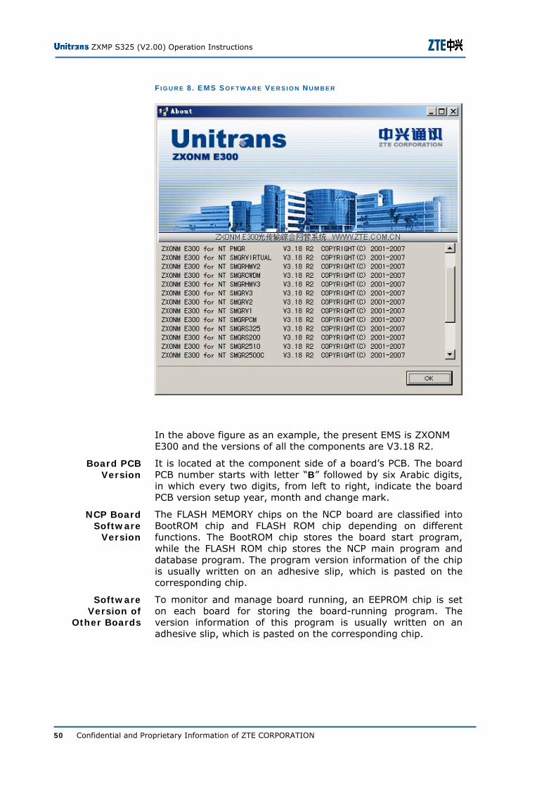
Select About option in the Help menu to show the information dialogue box for EMS software version, as shown in Figure 8.
Overview
Equipment Version
EMS Software Version
ZXMP S325 (V2.00) Operation Instructions
50 Confidential and Proprietary Information of ZTE CORPORATION
F I G U R E 8 . EMS S O F T W AR E V E R S I O N N U M B E R
In the above figure as an example, the present EMS is ZXONM E300 and the versions of all the components are V3.18 R2.
It is located at the component side of a board’s PCB. The board PCB number starts with letter “B” followed by six Arabic digits, in which every two digits, from left to right, indicate the board PCB version setup year, month and change mark.
The FLASH MEMORY chips on the NCP board are classified into BootROM chip and FLASH ROM chip depending on different functions. The BootROM chip stores the board start program, while the FLASH ROM chip stores the NCP main program and database program. The program version information of the chip is usually written on an adhesive slip, which is pasted on the corresponding chip.
To monitor and manage board running, an EEPROM chip is set on each board for storing the board-running program. The version information of this program is usually written on an adhesive slip, which is pasted on the corresponding chip.
Board PCB Version
NCP Board Software
Version
Software Version of
Other Boards

Chapter 5 - Equipment Upgrade
Confidential and Proprietary Information of ZTE CORPORATION 51
Upgrade Precautions Before performing upgrade, pay attention to the following precautions:
Perform the backup function to ensure rapid recovery of service in case of upgrade failure.
Make sure that the new version is completely compatible with the equipment to be upgraded.
ZXMP S325 (V2.00) Operation Instructions
52 Confidential and Proprietary Information of ZTE CORPORATION
Hardware Upgrade Hardware upgrade is used to change the old/(presently in-use) equipment hardware with the latest available or any other higher version of equipment.
Make sure to modify the corresponding hardware version information in the EMS software to eliminate the software and hardware from cooperation errors, for successful upgrade.
Chapter 5 - Equipment Upgrade
Confidential and Proprietary Information of ZTE CORPORATION 53
Upgrading EMS Software To upgrade the EMS Software.
1. Prepare for upgrade
i. Make sure the new software is available to upgrade EMS software.
ii. Check the compatibility of the board hardware or program with the EMS software.
iii. In case of even very minor incompatibility, do not upgrade the system till the proper arrangements of complete compatibility.
2. Back up or configure network data
i. The format data of network configuration of new version of EMS software is compatible with the old software
ii. The user can back up the network configuration information by using the back up function of EMS software.
iii. If the backup data of the old version of EMS software is incompatible with the new version, first install the new version of EMS software in another computer.
iv. Configure it and back up the network configuration data.
v. Copy the backup data to the EMS computer.
Note: User can easily recover the data after installing new EMS software version by above procedures.
3. Uninstall the EMS software of old version
If the EMS runs on the Windows 2000 platform, uninstall it through “Add/delete program”.
If the EMS runs on the UNIX platform, follow the steps below to uninstall it:
i. Execute the following commands to uninstall it:
# cd /opt/unitrans
# ./uninstall
ii. After command is executed, check whether the /opt/unitrans directory is cleared.
4. Install the EMS software of new version
Install the new version of EMS software according to latest version of the EMS operation manual.
Purpose
Steps
ZXMP S325 (V2.00) Operation Instructions
54 Confidential and Proprietary Information of ZTE CORPORATION
5. Recover or reconfigure the network configuration data
Use the data backup/recovery function of the EMS to recover the previously configure data back up.
6. Re-download and connect the NE device
i. Once the configuration data is re-downloaded to NE using the new version of EMS, check whether the monitoring and management operation of the EMS software on the NE is normal.
ii. If there is any abnormality, find the cause and solve the problem.
iii. When all the functions are normal, the EMS upgrade is complete and successful.
END OF STEPS
Chapter 5 - Equipment Upgrade
Confidential and Proprietary Information of ZTE CORPORATION 55
Upgrading Board Software Upgrading Software of NCP Board
To upgrade the NCP board software.
1. Carefully check/compare the NCP board software of new version with the EMS software for compatibility before upgrade.
2. Do not consider the upgrade in case of incompatibility.
3. The board software upgrade for the NCP board covers two parts: BootROM upgrade and NCP application/logic upgrade, which can be conducted separately as long as BootROM and the application/logic are compatible.
4. To upgrade the BootROM program, typically burn the new version of the BootROM program onto the chip by using the chip burner and replace with the chip on site.
5. To upgrade the application or logic of NCP board, it is necessary to write the application file onto the NCP board through FTP via the network interface. Refer to Chapter 1 for detailed operations.
END OF STEPS
Upgrading Software of Other Boards
To upgrade the software of other boards except NCP board.
1. Check the board software of the new version for compatibility with the NCP software and EMS before upgrading the board software.
2. Consider the necessity of simultaneous upgrading in case of incompatibility.
3. The upgrade of the board software covers board BootRom, its application and logic program upgrade.
4. The board BootROM needs no upgrade.
5. Both of these upgrades can conduct separately as long as board BootROM and the main program is compatible.
6. To upgrade the board BootROM program, burn the new version of the BootROM program onto the chip by using the chip burner and replace the chip on site.
Purpose
Steps
Purpose
Steps

ZXMP S325 (V2.00) Operation Instructions
56 Confidential and Proprietary Information of ZTE CORPORATION
7. To upgrade the board application or logic program, it is necessary to upload the upgrade program through FTP to the NCP board of the NE, and then load it onto the board to be upgraded. The operations are similar to NCP application/logic upgrade operations. Refer to Chapter 1 for details.
END OF STEPS
Confidential and Proprietary Information of ZTE CORPORATION 57
C h a p t e r 6
NE Address Definition and Route Configuration
This chapter describes how to set the NE IP address and EMS host IP address. The content in this chapter applies to all SDH NEs.
Caution: While configuring NE initial information, the NE IP addresses and the EMS host must be determined and written to the NE NCP board, which allows no random modification when the equipment operates normally.

ZXMP S325 (V2.00) Operation Instructions
58 Confidential and Proprietary Information of ZTE CORPORATION
NE IP Address Definition The NE IP address definition is same as the common IP address. However, the each byte meaning in NE IP address is redefined. The configuration principle and byte meanings vary with different mask formats.
FLSM Addressing
This topic states about Full Length Subnet Mask (FLSM) addressing and NE definitions.
Table 17 illustrates the NE IP address and subnet mask definitions.
T AB L E 17 . NE IP AD D R E S S A N D S U B N E T M AS K (FLSM) D E F I N I T I O N S
Item Description Remarks
NE IP address
byte 1.byte 2.byte 3.byte 4
The NE IP address contains three parts: area code, NE code, and NCP board number. Byte 1 serves as the area code, some address bits of byte 2 and byte 3 serve as the NE code, and the remaining address bits and byte 4 form the NCP board number.
The area ID combined with NE ID corresponds to the network address. The NCP board number corresponds to the host address.
Subnet mask 255.byte 2.byte 3.0
The result got from the logic AND operation of NE IP address and subnet mask defines each byte of NE IP address.
Table 18 illustrates the area ID, NE ID, and board ID.
Definitions
NE IP address and Subnet Mask
Definitions
Area ID, NE ID, and Board ID
Definitions
Chapter 6 - NE Address Definition and Route Configuration
Confidential and Proprietary Information of ZTE CORPORATION 59
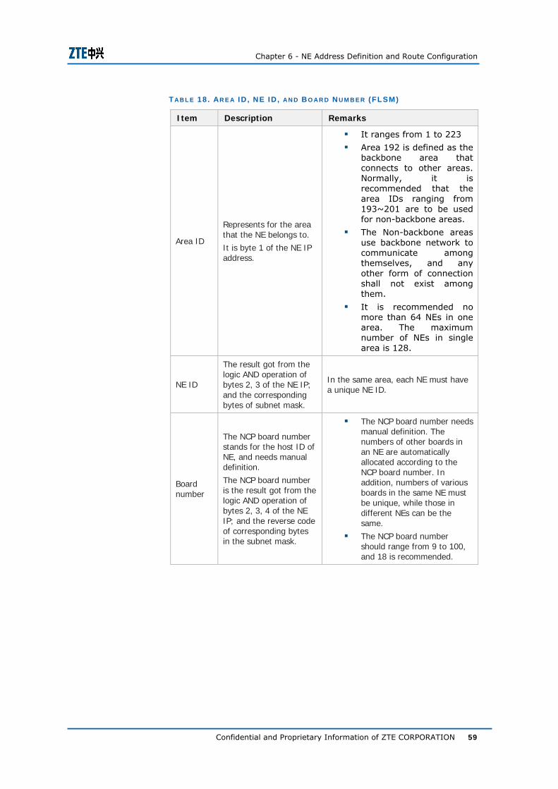
T AB L E 18 . AR E A ID , NE ID, AN D B O AR D N U M B E R (FLSM)
Item Description Remarks
Area ID
Represents for the area that the NE belongs to. It is byte 1 of the NE IP address.
It ranges from 1 to 223
Area 192 is defined as the backbone area that connects to other areas. Normally, it is recommended that the area IDs ranging from 193~201 are to be used for non-backbone areas.
The Non-backbone areas use backbone network to communicate among themselves, and any other form of connection shall not exist among them.
It is recommended no more than 64 NEs in one area. The maximum number of NEs in single area is 128.
NE ID
The result got from the logic AND operation of bytes 2, 3 of the NE IP; and the corresponding bytes of subnet mask.
In the same area, each NE must have a unique NE ID.
Board number
The NCP board number stands for the host ID of NE, and needs manual definition. The NCP board number is the result got from the logic AND operation of bytes 2, 3, 4 of the NE IP; and the reverse code of corresponding bytes in the subnet mask.
The NCP board number needs manual definition. The numbers of other boards in an NE are automatically allocated according to the NCP board number. In addition, numbers of various boards in the same NE must be unique, while those in different NEs can be the same.
The NCP board number should range from 9 to 100, and 18 is recommended.
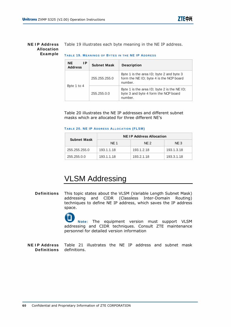
ZXMP S325 (V2.00) Operation Instructions
60 Confidential and Proprietary Information of ZTE CORPORATION
Table 19 illustrates each byte meaning in the NE IP address.
T AB L E 19 . M E AN I N G S O F B Y T E S I N T H E NE IP AD D R E S S
NE IP Address Subnet Mask Description
255.255.255.0 Byte 1 is the area ID; byte 2 and byte 3 form the NE ID; byte 4 is the NCP board number.
Byte 1 to 4
255.255.0.0 Byte 1 is the area ID; byte 2 is the NE ID; byte 3 and byte 4 form the NCP board number.
Table 20 illustrates the NE IP addresses and different subnet masks which are allocated for three different NE’s
T AB L E 20 . NE IP AD D R E S S AL L O C AT I O N (FLSM)
NE IP Address Allocation Subnet Mask
NE 1 NE 2 NE 3
255.255.255.0 193.1.1.18 193.1.2.18 193.1.3.18
255.255.0.0 193.1.1.18 193.2.1.18 193.3.1.18
VLSM Addressing
This topic states about the VLSM (Variable Length Subnet Mask) addressing and CIDR (Classless Inter-Domain Routing) techniques to define NE IP address, which saves the IP address space.
Note: The equipment version must support VLSM addressing and CIDR techniques. Consult ZTE maintenance personnel for detailed version information
Table 21 illustrates the NE IP address and subnet mask definitions.
NE IP Address Allocation
Example
Definitions
NE IP Address Definitions

Chapter 6 - NE Address Definition and Route Configuration
Confidential and Proprietary Information of ZTE CORPORATION 61
T AB L E 21 . D E F I N I T I O N S O F NE IP AD D R E S S AN D S U B N E T M AS K (VLSM)
Item Description Remarks
NE IP address Byte 1. to Byte 4
It comprises three parts: area ID, ECC subnet ID, NE ID.
Each NE needs to be allocated with an IP address. In the same ECC subnet (an interconnected ECC network), the NE IP address must be unique.
Subnet mask Byte 1 to Byte 4
The result got from the logic AND operation of subnet mask and NE IP address defines the specific meaning of each byte in the NE IP address.
Byte 1 is generally 255, and byte 4 can be set randomly.
Table 22 illustrates the area ID, ECC subnet ID, and NE ID for VLSM.
T AB L E 22 . D E F I N I T I O N S O F AR E A ID , ECC S U B N E T ID , AN D NE ID (VLSM)
Item Description Remarks
Area ID
Represents for the area that the NE belongs to
It is byte 1 of NE IP address
For a complicated ECC subnet, the multi-area configuration must be adopted due to the limitation of NE processing capability and the requirement of dynamic route protocol.
Refer to the description of area ID in Table 18 for division principle and requirement of the area ID.
ECC subnet ID
Represents for the ECC subnet ID that the NE belongs to the same subnet.
It is byte 2 of NE IP address.
A complicated ECC subnet can contain multiple areas.
NE ID
It is the result got from the logic AND operation of byte 3, 4 of the NE IP address; and corresponding bytes of the subnet mask.
-
Area ID, ECC Subnet ID, and
NE ID Definitions

ZXMP S325 (V2.00) Operation Instructions
62 Confidential and Proprietary Information of ZTE CORPORATION
The subnet mask is 255.255.255.252, and the NE addresses allocated are as follows (63 NE addresses in total) for an address space of 193.193.193.*:
193.193.193.5
193.193.193.9
193.193.193.13
193.193.193.17
193.193.193.21
193.193.193.25
......
193.193.193.249
193.193.193.253
Where, byte 1 is the area ID and byte 2 is the ECC subnet ID. The result of logical ‘AND’ operation on NE IP byte 3 and subnet mask byte 3, and the result of logical ‘AND’ operation on NE IP byte 4 and subnet mask byte 4 comprise the NE ID.
PortNum is defined as the number of available DCC overhead channels in the NE, i.e. the channels of the installed board in the NE, including optical interfaces and electrical interfaces. It is necessary to define one IP address for each optical/electrical interface.
If byte 4 of the subnet mask is zero, the board IP address is allocated at byte 4.
Suppose the NE IP address, i.e. the NCP board IP address is “byte 1.byte 2.byte 3.byte 4”, then the IP addresses of other boards are allocated to numbers ranging from “byte 1.byte 2.byte 3.(byte 4+1)” to “byte 1.byte 2.byte 3.(byte 4+PortNum)”.
If byte 4 of the subnet mask is not zero, the board IP address is allocated at byte 2.
Suppose the NE IP address is “byte 1.byte 2.byte 3.byte 4”, then the IP addresses of other boards are allocated to numbers ranging from “byte 1.(byte 2+1).byte 3.byte 4” to “byte 1.(byte 2+PortNum).byte 3.byte 4”.
Note: Since the NCP board IP address is invisible to EMS, it will not affect the outside network, which means it will not conflict with the outside network address. Therefore, it is only necessary to ensure that the addresses inside the SDH internal communication network are unique. In the same ECC network, the fourth bytes of subnet masks being zero and being non-zero should not coexist.
NE IP Address Allocation
Example
Board IP Address
Definition
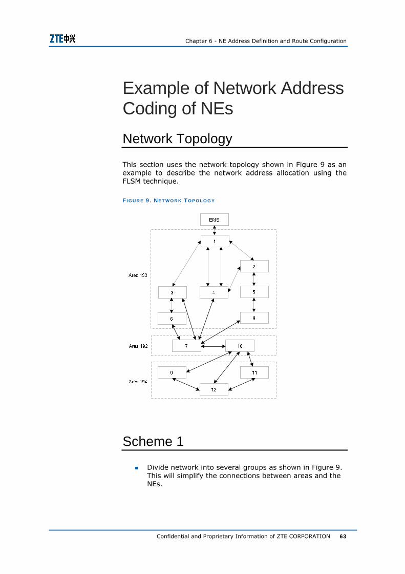
Chapter 6 - NE Address Definition and Route Configuration
Confidential and Proprietary Information of ZTE CORPORATION 63
Example of Network Address Coding of NEs Network Topology
This section uses the network topology shown in Figure 9 as an example to describe the network address allocation using the FLSM technique.
F I G U R E 9 . NE T W O R K TO P O L O G Y
Scheme 1
Divide network into several groups as shown in Figure 9. This will simplify the connections between areas and the NEs.

ZXMP S325 (V2.00) Operation Instructions
64 Confidential and Proprietary Information of ZTE CORPORATION
Group NEs 1, 2, 3, 4, 5, 6, and 8 into area 193. All these NEs are relatively centralized, among which there are many connections, and they form a mesh topology.
Group NE’s 9, 11, and 12 are considered into single area 194. All these NE’s are relatively centralized and form a ring topology.
Group NE’s 7 and 10 into area 192. There is only one single connection between areas 193 and 194 via NE’s 7 and 10. Therefore, NE’s 7 and 10 are considered as the backbone area (area 192) for connecting other areas.
Network topology area definitions and NE IP address configuration are listed in the Table 23.
T AB L E 23 . AR E A D E F I N I T I O N S AN D NE IP AD D R E S S C O N F I G U R AT I O N S
NEs in the Area Area Number
NE NE IP Address
Access NE 1 193.1.1.18
NE 2 193.1.2.18
NE 3 193.1.3.18
NE 4 193.1.4.18
NE 5 193.1.5.18
NE 6 193.1.6.18
Area 193
NE 8 193.1.8.18
NE 9 194.1.9.18
NE 11 194.1.11.18 Area 194
NE 12 194.1.12.18
NE 7 192.1.7.18 Area 192 (backbone area) NE 10 192.1.10.18
Note: The network subnet mask is 255.255.255.0, and the EMS host IP address is 193.1.1.1.

Chapter 6 - NE Address Definition and Route Configuration
Confidential and Proprietary Information of ZTE CORPORATION 65
Scheme 2
Figure 9 illustrates the network. Since there are relatively few NEs, all these NEs can be simply allocated into one area, in which the backbone area is not needed.
Example: Consider all the NEs in the network topology as one area 193 and their NE IP address are listed in Table 24.
T AB L E 24 . NE IP AD D R E S S O F AL L NE S I N T H E N E T W O R K
NE NE IP Address NE NE IP Address
Access NE 1 193.1.1.18 NE 2 193.1.2.18
NE 3 193.1.3.18 NE 4 193.1.4.18
NE 5 193.1.5.18 NE 6 193.1.6.18
NE 7 193.1.7.18 NE 8 193.1.8.18
NE 9 193.1.9.18 NE 10 193.1.10.18
NE 11 193.1.11.18 NE 12 193.1.12.18
Note:
The network subnet mask is 255.255.255.0, and the EMS host IP address is 193.1.1.1.
Although allocating all NEs into the same area is simple, the efficiency of ECC route algorithm will be affected if the number of NEs is large.
Therefore, this method only applies to applications with a small number of NEs. Normally, the maximum number of NEs in one area should not exceed 120.

ZXMP S325 (V2.00) Operation Instructions
66 Confidential and Proprietary Information of ZTE CORPORATION
EMS Host Address/Route Configuration In order to enable EMS to manage all the NEs properly, it is necessary to set on the EMS host the IP routes that can reach the whole network.
EMS Host Address Definitions
Table 25 illustrates EMS host address definitions
T AB L E 25 . EMS H O S T AD D R E S S D E F I N I T I O N S
Item Description Configuration Principle
IP address
Defines the EMS host network address.
Employs the IP address format: byte 1.byte 2.byte 3.byte 4.
The result got from the logic AND operation of the EMS host IP address and the subnet mask must be within the same network section as the access NE, i.e. the EMS host and the gateway NE should have the same network ID.
The EMS host ID should be less than the gateway NE host ID (i.e. the NCP board number). The EMS host ID is suggested to range from 1 to 9, starting from 1.
Subnet mask
Defines the subnet mask of the EMS host.
Used to divide network section by performing logic AND operation with the EMS host IP address.
The subnet mask is suggested to be the same as the subnet mask of access NE.
Gateway address
Defines the gateway address of the EMS host. Set the access NE as the gateway NE.

Chapter 6 - NE Address Definition and Route Configuration
Confidential and Proprietary Information of ZTE CORPORATION 67
Configuring EMS Host Address
To configure the EMS host address for the transmission network show in Figure 9.
1. Consider the transmission network show in Figure 9. Set the EMS IP address as 193.1.1.1 which is within the same network section as gateway NE 1, with the network adapter of EMS host.
2. Make sure EMS host can reach the access NE.
3. Set the gateway NE IP address as 193.1.1.18.
4. Make sure EMS host can reach the area 193.
5. Set the routes on the EMS host to reach NEs in area 192 and area 194.
END OF STEPS
Route Configuration Methods
There are two methods to set routes on EMS:
Run the OSPF dynamic routing protocol at the EMS host side
This method requires no route setting. However, be cautious when using dynamic route and do not advertise those invalid or possibly repeated routes to the network, to avoid some unreachable NEs or too large routing table. In addition, the application of dynamic route increases the operating load of EMS host.
Therefore, it is recommended to set static route or default route for the EMS host, so as to filter out IP packets that are irrelevant to the network, thus increases the operating efficiency of EMS.
Set default route or static route directing to the NE that directly connects with the EMS host. Delete other routes that are repeatedly configured.
As an example, consider the network shown in Figure 9, the methods of setting default route and static route for EMS host are as follows:
Set the default route
route add default 193.1.1.18
This default route means that all IP packets, without showing route locally, have to pass NE 1.
Purpose
Steps
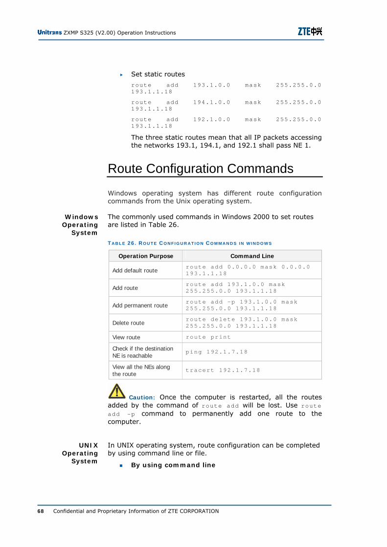
ZXMP S325 (V2.00) Operation Instructions
68 Confidential and Proprietary Information of ZTE CORPORATION
Set static routes
route add 193.1.0.0 mask 255.255.0.0 193.1.1.18
route add 194.1.0.0 mask 255.255.0.0 193.1.1.18
route add 192.1.0.0 mask 255.255.0.0 193.1.1.18
The three static routes mean that all IP packets accessing the networks 193.1, 194.1, and 192.1 shall pass NE 1.
Route Configuration Commands
Windows operating system has different route configuration commands from the Unix operating system.
The commonly used commands in Windows 2000 to set routes are listed in Table 26.
T AB L E 26 . R O U T E C O N F I G U R AT I O N C O M M AN D S I N W I N D O W S
Operation Purpose Command Line
Add default route route add 0.0.0.0 mask 0.0.0.0 193.1.1.18
Add route route add 193.1.0.0 mask 255.255.0.0 193.1.1.18
Add permanent route route add –p 193.1.0.0 mask 255.255.0.0 193.1.1.18
Delete route route delete 193.1.0.0 mask 255.255.0.0 193.1.1.18
View route route print
Check if the destination NE is reachable
ping 192.1.7.18
View all the NEs along the route
tracert 192.1.7.18
Caution: Once the computer is restarted, all the routes added by the command of route add will be lost. Use route add –p command to permanently add one route to the computer.
In UNIX operating system, route configuration can be completed by using command line or file.
By using command line
Windows Operating
System
UNIX Operating
System

Chapter 6 - NE Address Definition and Route Configuration
Confidential and Proprietary Information of ZTE CORPORATION 69
Table 27 illustrates the commonly used command lines to set route.
T AB L E 27 . R O U T E C O N F I G U R AT I O N C O M M AN D S L I N E S I N U N I X
Operation Purpose Command Line
Add default route route add default 193.1.1.18 1
Add route
route add 193.1.0.0 255.255.0.0 193.1.1.18 1 (HP-UX)
route add net 193.1.0.0 193.1.1.18 1 (Solaris)
Add permanent route route delete 193.1.0.0
Delete route netstat
View route ping 192.1.7.18
Check if the destination NE is reachable
tracertroute 192.1.7.18
Caution: Once the computer is restarted, all the routes added by the command lines will be lost. Modify the configuration file and save the changes to permanently add one route to the computer.
By Modifying the Configuration File
In different UNIX systems, the configuration file location and the modification operation are different.
HP-UX platform
Modify the /etc/rc.config.d/netconf file in the document editor. The configuration commands in the file will automatically effect and save permanently after the system restart.
Table 28 illustrates the route configuration commands in configuration file.
T AB L E 28 . R O U T E C O N F I G U R AT I O N C O M M AN D S I N HP-UX
Operation Purpose File Modifications Corresponding
Command Line
Add default route
ROUTE_DESTINATION[0]="default"
ROUTE_MASK[0]=""
ROUTE_GATEWAY[0]= 193.1.1.18
ROUTE_COUNT[0]=1
ROUTE_ARGS[0]= ""
route add default 193.1.1.18 1
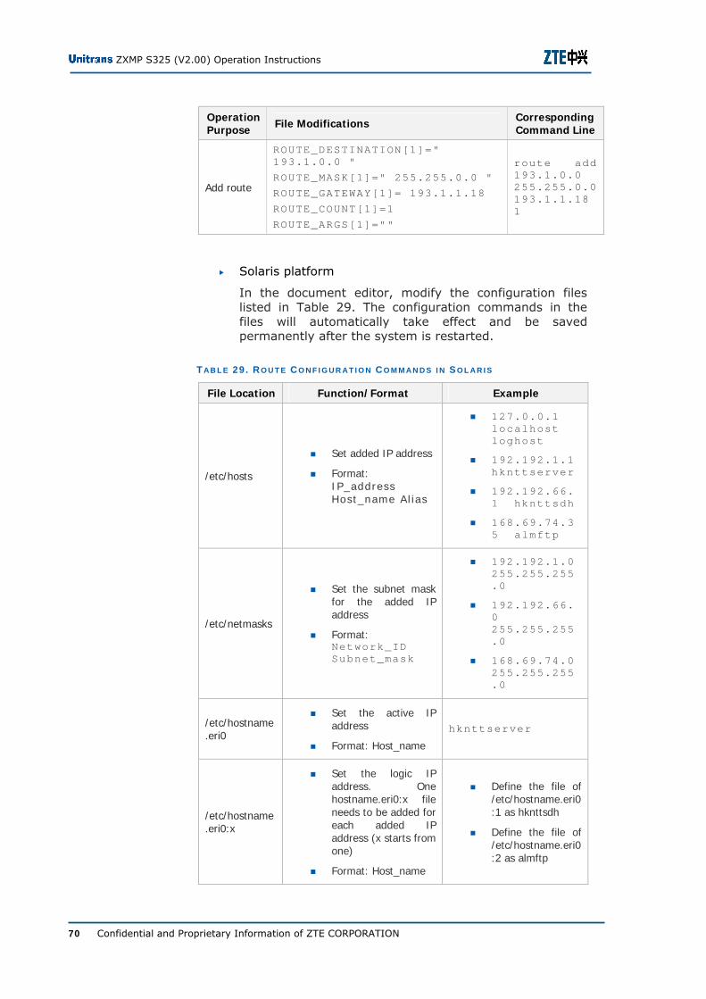
ZXMP S325 (V2.00) Operation Instructions
70 Confidential and Proprietary Information of ZTE CORPORATION
Operation Purpose File Modifications Corresponding
Command Line
Add route
ROUTE_DESTINATION[1]=" 193.1.0.0 "
ROUTE_MASK[1]=" 255.255.0.0 "
ROUTE_GATEWAY[1]= 193.1.1.18
ROUTE_COUNT[1]=1
ROUTE_ARGS[1]=""
route add 193.1.0.0 255.255.0.0 193.1.1.18 1
Solaris platform
In the document editor, modify the configuration files listed in Table 29. The configuration commands in the files will automatically take effect and be saved permanently after the system is restarted.
T AB L E 29 . R O U T E C O N F I G U R AT I O N C O M M AN D S I N S O L AR I S
File Location Function/Format Example
/etc/hosts
Set added IP address
Format: IP_address Host_name Al ias
127.0.0.1 localhost loghost
192.192.1.1 hknttserver
192.192.66.1 hknttsdh
168.69.74.35 almftp
/etc/netmasks
Set the subnet mask for the added IP address
Format: Network_ID Subnet_mask
192.192.1.0 255.255.255.0
192.192.66.0 255.255.255.0
168.69.74.0 255.255.255.0
/etc/hostname.eri0
Set the active IP address
Format: Host_name
hknttserver
/etc/hostname.eri0:x
Set the logic IP address. One hostname.eri0:x file needs to be added for each added IP address (x starts from one)
Format: Host_name
Define the file of /etc/hostname.eri0:1 as hknttsdh
Define the file of /etc/hostname.eri0:2 as almftp
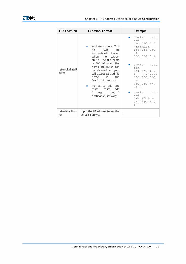
Chapter 6 - NE Address Definition and Route Configuration
Confidential and Proprietary Information of ZTE CORPORATION 71
File Location Function/Format Example
/etc/rc2.d/zteRouter
Add static route. This file will be automatically loaded when the system starts. The file name is S96zteRouter. The name zteRouter can be defined at your will except existed file name in the /etc/rc2.d directory
Format to add one route: route add [ host | net ] destination gateway
route add net 192.192.0.0 –netmask 255.255.192.0 192.192.1.6 1
route add net 192.192.64.0 –netmask 255.255.192.0 192.192.66.18 1
route add net 168.65.0.0 168.69.74.1 5
/etc/defaultrouter
Input the IP address to set the default gateway -
ZXMP S325 (V2.00) Operation Instructions
72 Confidential and Proprietary Information of ZTE CORPORATION
This page is intentionally blank.
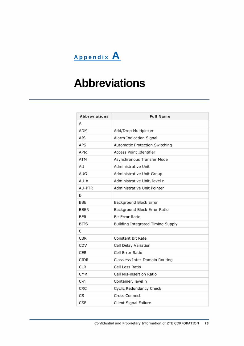
Confidential and Proprietary Information of ZTE CORPORATION 73
A p p e n d i x A
Abbreviations
Abbreviations Full Name
A
ADM Add/Drop Multiplexer
AIS Alarm Indication Signal
APS Automatic Protection Switching
APId Access Point Identifier
ATM Asynchronous Transfer Mode
AU Administrative Unit
AUG Administrative Unit Group
AU-n Administrative Unit, level n
AU-PTR Administrative Unit Pointer
B
BBE Background Block Error
BBER Background Block Error Ratio
BER Bit Error Ratio
BITS Building Integrated Timing Supply
C
CBR Constant Bit Rate
CDV Cell Delay Variation
CER Cell Error Ratio
CIDR Classless Inter-Domain Routing
CLR Cell Loss Ratio
CMR Cell Mis-insertion Ratio
C-n Container, level n
CRC Cyclic Redundancy Check
CS Cross Connect
CSF Client Signal Failure
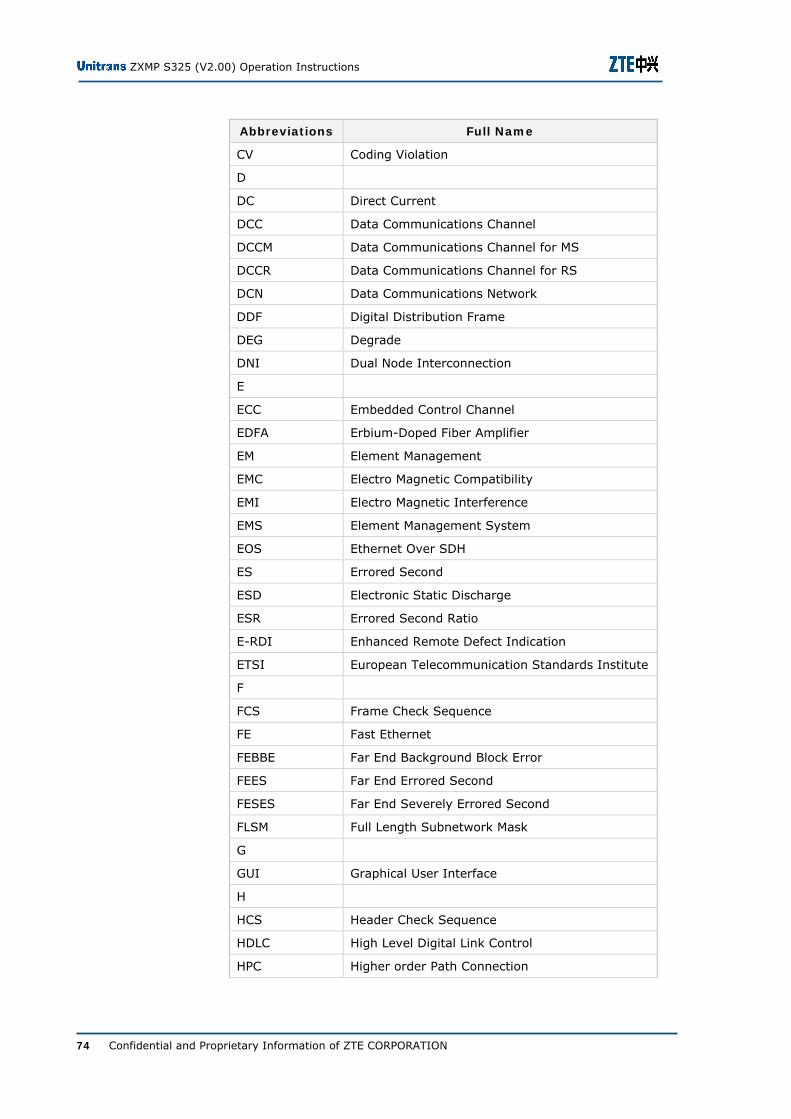
ZXMP S325 (V2.00) Operation Instructions
74 Confidential and Proprietary Information of ZTE CORPORATION
Abbreviations Full Name
CV Coding Violation
D
DC Direct Current
DCC Data Communications Channel
DCCM Data Communications Channel for MS
DCCR Data Communications Channel for RS
DCN Data Communications Network
DDF Digital Distribution Frame
DEG Degrade
DNI Dual Node Interconnection
E
ECC Embedded Control Channel
EDFA Erbium-Doped Fiber Amplifier
EM Element Management
EMC Electro Magnetic Compatibility
EMI Electro Magnetic Interference
EMS Element Management System
EOS Ethernet Over SDH
ES Errored Second
ESD Electronic Static Discharge
ESR Errored Second Ratio
E-RDI Enhanced Remote Defect Indication
ETSI European Telecommunication Standards Institute
F
FCS Frame Check Sequence
FE Fast Ethernet
FEBBE Far End Background Block Error
FEES Far End Errored Second
FESES Far End Severely Errored Second
FLSM Full Length Subnetwork Mask
G
GUI Graphical User Interface
H
HCS Header Check Sequence
HDLC High Level Digital Link Control
HPC Higher order Path Connection
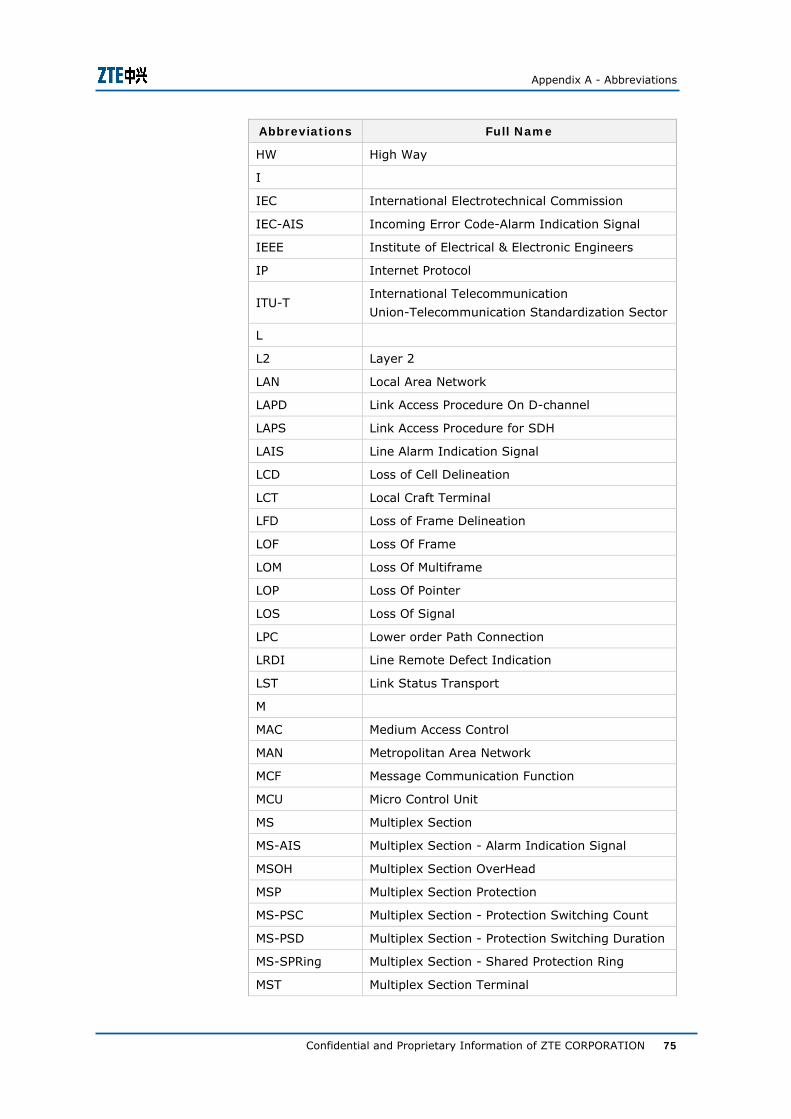
Appendix A - Abbreviations
Confidential and Proprietary Information of ZTE CORPORATION 75
Abbreviations Full Name
HW High Way
I
IEC International Electrotechnical Commission
IEC-AIS Incoming Error Code-Alarm Indication Signal
IEEE Institute of Electrical & Electronic Engineers
IP Internet Protocol
ITU-T International Telecommunication
Union-Telecommunication Standardization Sector
L
L2 Layer 2
LAN Local Area Network
LAPD Link Access Procedure On D-channel
LAPS Link Access Procedure for SDH
LAIS Line Alarm Indication Signal
LCD Loss of Cell Delineation
LCT Local Craft Terminal
LFD Loss of Frame Delineation
LOF Loss Of Frame
LOM Loss Of Multiframe
LOP Loss Of Pointer
LOS Loss Of Signal
LPC Lower order Path Connection
LRDI Line Remote Defect Indication
LST Link Status Transport
M
MAC Medium Access Control
MAN Metropolitan Area Network
MCF Message Communication Function
MCU Micro Control Unit
MS Multiplex Section
MS-AIS Multiplex Section - Alarm Indication Signal
MSOH Multiplex Section OverHead
MSP Multiplex Section Protection
MS-PSC Multiplex Section - Protection Switching Count
MS-PSD Multiplex Section - Protection Switching Duration
MS-SPRing Multiplex Section - Shared Protection Ring
MST Multiplex Section Terminal

ZXMP S325 (V2.00) Operation Instructions
76 Confidential and Proprietary Information of ZTE CORPORATION
Abbreviations Full Name
MTIE Maximum Time Interval Error
MUPI Mismatch User Payload Identifier
N
NE Network Element
NEF Network Element Function
NEL Network Element Layer
NMS Network Management System
NNI Network Node Interface
NRZ Non-Return-to-Zero
O
OAM Operation, Administration and Maintenance
OCXO Oven Controlled Crystal Oscillator
ODI Outgoing defect Indication
OFS Out of Frame Second
OOF Out of Frame
OSF Operation System Function
OSI Open System Interconnect
P
PAIS Path Alarm Indication Signal
PCM Pulse Code Modulation
PDH Plesiochronous Digital Hierarchy
PGND Protection GND
PHY Physical Layer Device
PJC- Negative Pointer Justification Count
PJC+ Positive Pointer Justification Count
POH Path OverHead
POS Packet Over SDH
PPP Point to Point Protocol
PRC Primary Reference Clock
PRDI Path Remote Defect Indication
PSC Protection Switch Count
PSD Protection Switch Duration
Q
QA Q Adaptor
QoS Quality of Service
R

Appendix A - Abbreviations
Confidential and Proprietary Information of ZTE CORPORATION 77
Abbreviations Full Name
RAM Random Access Memory
RDI Remote Defect Indication
REG Regenerator
REI Remote Error Indication
RFI Remote Failure Indication
RIP Routing Information Protocol
RMII Reduced Medium Independent Interface
RS Regenerator Section
RSOH Regenerator Section OverHead
S
SAR Segmentation and Reassembly
SDH Synchronous Digital Hierarchy
SEC SDH Equipment Clock
SEMF Synchronous Equipment Management Function
SES Severely Errored Second
SESR Severely Errored Second Ratio
SETS Synchronous Equipment Timing Source
SFP Small Form Factor Pluggable
SMCC Subnetwork Management Control Center
SMN SDH Management Network
SMS SDH Management Subnetwork
SNC Subnetwork Connection
SNCP Subnetwork Connection Protection
SOH Section Overhead
SPRING Shared Protection Ring
SSF Service Signal Failure
SSM Synchronization Status Message
STM-N Synchronous Transport Module Leve-N
T
TC-LOM Tandem Connection - Loss Of Multiframe
TC-RDI Tandem Connection - Remote Defect Indication
TC-TIM Tandem Connection - Trace Identifier Mismatch
TCP Transport Control Protocol
TDM Time Division Multiplex
TM Terminal Multiplexer
TTL Time To Live
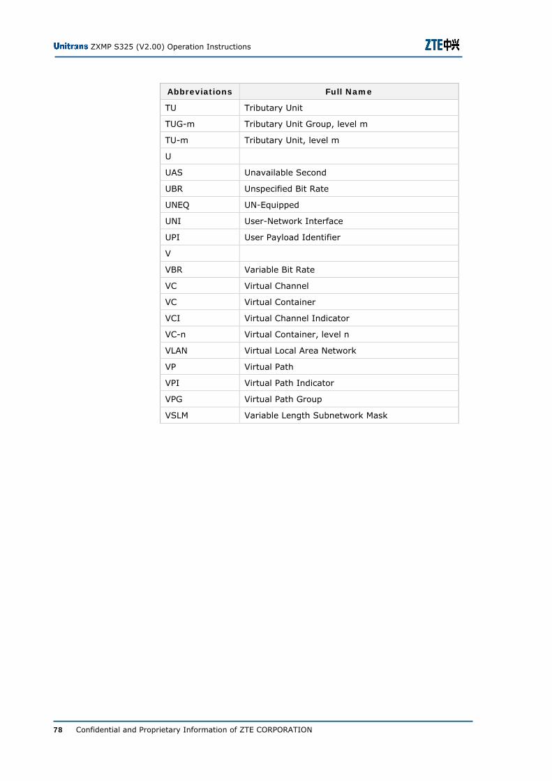
ZXMP S325 (V2.00) Operation Instructions
78 Confidential and Proprietary Information of ZTE CORPORATION
Abbreviations Full Name
TU Tributary Unit
TUG-m Tributary Unit Group, level m
TU-m Tributary Unit, level m
U
UAS Unavailable Second
UBR Unspecified Bit Rate
UNEQ UN-Equipped
UNI User-Network Interface
UPI User Payload Identifier
V
VBR Variable Bit Rate
VC Virtual Channel
VC Virtual Container
VCI Virtual Channel Indicator
VC-n Virtual Container, level n
VLAN Virtual Local Area Network
VP Virtual Path
VPI Virtual Path Indicator
VPG Virtual Path Group
VSLM Variable Length Subnetwork Mask

Confidential and Proprietary Information of ZTE CORPORATION 79
Figures
Figure 1. Local Upgrade Flowchart ........................................7
Figure 2. Preparations for Local Upgrade Operations................8
Figure 3. Remote Upgrade Flowchart ................................... 16
Figure 4. Login Management Dialog Box .............................. 32
Figure 5. Board Replacement Flowchart ............................... 34
Figure 6. Unplugging LP1x1 Board ...................................... 36
Figure 7. Plugging LP1x1 Board .......................................... 37
Figure 8. EMS Software Version Number .............................. 50
Figure 9. Network Topology ............................................... 63

ZXMP S325 (V2.00) Operation Instructions
80 Confidential and Proprietary Information of ZTE CORPORATION
This page is intentionally blank.

Confidential and Proprietary Information of ZTE CORPORATION 81
Tables
Table 1. Chapter Summary ...................................................i
Table 2. Typographical Conventions ...................................... ii
Table 3. Mouse Operation Conventions ................................. iii
Table 4. Configuration details ............................................. 10
Table 5. Command Parameters of d-upgrade ........................ 12
Table 6. Fields to be Verified for Upgraded Application/Logic... 12
Table 7. Command Parameters........................................... 13
Table 8. d-upgrade Command Parameters............................ 18
Table 9. Fields to be Verified for Upgraded Application/Logic... 19
Table 10. d-get-status Command Parameters ....................... 20
Table 11. d-try Command Parameters ................................. 20
Table 12. Fields to be Verified in the Original Standby area..... 21
Table 13. d-get-status Command Parameters ....................... 22
Table 14. d-active Command Parameters ............................. 22
Table 15. Fields to be Verified for Activated Application/Logic.. 23
Table 16. d-get-status Command Parameters ....................... 24
Table 17. NE IP Address and Subnet Mask (FLSM) Definitions .58
Table 18. Area ID, NE ID, and Board Number (FLSM) ............ 59
Table 19. Meanings of Bytes in the NE IP Address ................. 60
Table 20. NE IP Address Allocation (FLSM) ........................... 60
Table 21. Definitions of NE IP Address and Subnet Mask (VLSM)..................................................................................... 61
Table 22. Definitions of Area ID, ECC Subnet ID, and NE ID (VLSM) ........................................................................... 61
Table 23. Area Definitions and NE IP Address Configurations .. 64
Table 24. NE IP Address of All NEs in the Network................. 65
Table 25. EMS Host Address Definitions ............................... 66
Table 26. Route Configuration Commands in windows............ 68
Table 27. Route Configuration Commands Lines in Unix ......... 69
Table 28. Route Configuration Commands in HP-UX............... 69
ZXMP S325 (V2.00) Operation Instructions
82 Confidential and Proprietary Information of ZTE CORPORATION
Table 29. Route Configuration Commands in Solaris .............. 70