gallery.technet.microsoft.com · web view4.2.2fabric management memory (ram)16. ... 5.4.6virtual...
TRANSCRIPT

Fabric Management Architecture Guide
9-May-23Version 2.1 (Public version)
Prepared byJeff Baker, Adam Fazio, Joel Yoker, David Ziembicki, Thomas Ellermann, Robert Larson, Aaron Lightle, Michael Lubanski, Ray Maker, TJ Onishile, Ian Nelson, Shai Ofek, Artem Pronichkin, Anders Ravnholt, Ryan Sokolowski, Avery Spates, Andrew Weiss, Yuri Diogenes, Michel Luescher, Robert Heringa, Tiberiu Radu, Elena Kozylkova, Boklyn Wong, Jim Dial, Tom Shinder
Infrastructure-as-a-Service Product Line Architecture
Copyright information
© 2014 Microsoft Corporation. All rights reserved. This document is provided “as-is.” Information and views expressed in this document, including URL and other Internet website references, may change without notice. You bear the risk of using it.Some examples are for illustration only and are fictitious. No real association is intended or inferred.This document does not provide you with any legal rights to any intellectual property in any Microsoft product. You may copy and use this document for your internal, reference purposes.
Page 2Infrastructure-as-a-Service Product Line ArchitecturePrepared by Microsoft“Infrastructure-as-a-Service Fabric Management Architecture Guide"
Table of Contents
1 Introduction...............................................................................................71.1 Scope........................................................................................................................71.2 Microsoft Private Cloud Fast Track............................................................................71.3 Microsoft Services.....................................................................................................8
2 IaaS Product Line Architecture Overview...................................................92.1 IaaS Reference Architectures....................................................................................92.2 Product Line Architecture Fabric Design Patterns....................................................10
2.3 System Center Licensing..................................................................................11
3 Cloud Services Foundation Architecture..................................................123.1 Cloud Services Foundation Reference Model...........................................................12
4 Cloud Services Management Architecture...............................................144.1 Fabric and Fabric Management...............................................................................14
4.1.1 Fabric..............................................................................................................144.1.2 Fabric Management.......................................................................................15
4.2 Fabric Management Host Cluster Architecture........................................................154.2.1 Fabric Management Compute (CPU)............................................................154.2.2 Fabric Management Memory (RAM).............................................................164.2.3 Fabric Management Network........................................................................164.2.4 Fabric Management Storage Connectivity..................................................164.2.5 Fabric Management Storage........................................................................17
4.3 Fabric Management Architecture............................................................................174.3.1 System Center Component Scalability........................................................174.3.2 Prerequisite Infrastructure...........................................................................184.3.3 Consolidated SQL Server Design.................................................................244.3.4 Virtual Machine Manager (VMM)..................................................................304.3.5 Operations Manager......................................................................................314.3.6 Service Manager Management Server and Data Warehouse Management Server 334.3.7 Orchestrator...................................................................................................354.3.8 Service Reporting..........................................................................................374.3.9 Service Provider Foundation (SPF)..............................................................38
Page 3Infrastructure-as-a-Service Product Line ArchitecturePrepared by Microsoft“Infrastructure-as-a-Service Fabric Management Architecture Guide"

4.3.10 Service Management Automation................................................................384.3.11 Windows Azure Pack......................................................................................394.3.12 App Controller................................................................................................464.3.13 Data Protection Manager..............................................................................464.3.14 Fabric Management Requirement Summary..............................................47
5 Management and Support.......................................................................535.1 Fabric Management.................................................................................................53
5.1.1 Hardware Integration....................................................................................545.1.2 Service Maintenance.....................................................................................545.1.3 Resource Optimization..................................................................................555.1.4 Server Out-of-Band Management Configuration........................................56
5.2 Storage Support......................................................................................................565.2.1 Storage Integration and Management........................................................565.2.2 Storage Management....................................................................................57
5.3 Network Support.....................................................................................................585.3.1 Network Integration......................................................................................585.3.2 Network Management...................................................................................59
5.4 Deployment and Provisioning..................................................................................705.4.1 Fabric Provisioning........................................................................................705.4.2 VMware vSphere ESX Hypervisor Management.........................................715.4.3 Virtual Machine Manager Clouds.................................................................725.4.4 Virtual Machine Provisioning and Deprovisioning......................................735.4.5 IT Service Provisioning..................................................................................745.4.6 Virtual Machine Manager Library.................................................................77
5.5 Service Monitoring...................................................................................................785.6 Service Reporting....................................................................................................78
5.6.1 System Center Service Reporting................................................................805.7 Service Management...............................................................................................81
5.7.1 Service Management System.......................................................................835.7.2 User Self-Service...........................................................................................835.7.3 Service Delivery.............................................................................................84
5.8 Usage and Billing.....................................................................................................865.8.1 Chargeback vs. Showback............................................................................865.8.2 Developing a Chargeback Model.................................................................86
Page 4Infrastructure-as-a-Service Product Line ArchitecturePrepared by Microsoft“Infrastructure-as-a-Service Fabric Management Architecture Guide"
5.8.3 System Center Chargeback Capabilities.....................................................875.9 Data Protection and Disaster Recovery...................................................................88
5.9.1 Windows Azure Backup.................................................................................895.9.2 Data Protection Manager..............................................................................905.9.3 Hyper-V Recovery Manager..........................................................................92
5.10 Consumer and Provider Portal.................................................................................925.10.1 Virtual Machine Role Service (VM Role)......................................................925.10.2 Windows Azure Pack Web Sites Service......................................................935.10.3 SQL Tenant Database Service......................................................................945.10.4 MySQL Tenant Database Service.................................................................94
5.11 Change Management..............................................................................................945.11.1 Release and Deployment Management.......................................................945.11.2 Incident and Problem Management.............................................................955.11.3 Configuration Management..........................................................................95
5.12 Process Automation.................................................................................................955.12.1 Automation Options.......................................................................................96
6 Service Delivery.......................................................................................977 Service Operations.................................................................................1008 Disaster Recovery Considerations.........................................................102
8.1 Overview...............................................................................................................1028.1.1 Hyper-V Replica...........................................................................................1028.1.2 Multisite Failover Clusters..........................................................................1038.1.3 Backup and Restore....................................................................................104
8.2 Recovering from a Disaster...................................................................................1048.3 Component Overview and Order of Operations.....................................................1058.4 Virtual Machine Manager.......................................................................................107
8.4.1 Virtual Machine Manager Console Recovery............................................1088.4.2 SQL Server Recovery..................................................................................1108.4.3 Library Server Recovery.............................................................................1118.4.4 Integration Point Recovery.........................................................................111
8.5 Operations Manager..............................................................................................1138.5.1 Hyper-V Replica and Operations Manager................................................1148.5.2 Audit Collection Service Disaster Recovery Considerations...................1158.5.3 Gateway Disaster Recovery Considerations.............................................115
Page 5Infrastructure-as-a-Service Product Line ArchitecturePrepared by Microsoft“Infrastructure-as-a-Service Fabric Management Architecture Guide"

8.5.4 SQL Database Instances Disaster Recovery Considerations..................1158.5.5 Web Console Disaster Recovery Considerations.....................................115
8.6 Orchestrator..........................................................................................................1168.6.1 Single-Site Deployment with Hyper-V Replica.........................................1168.6.2 Runbook Design Considerations................................................................1168.6.3 Database Resiliency with SQL Always On Availability Groups...............1178.6.4 Disaster Recovery of Orchestrator Using Data Protection Manager.....117
8.7 Service Manager....................................................................................................1188.7.1 Service Manager Databases.......................................................................1188.7.2 Workflow Initiator Role...............................................................................1188.7.3 Management Server Console Access.........................................................1188.7.4 Service Manager Connectors.....................................................................119
9 Security Considerations.........................................................................1219.1 Protected Infrastructure........................................................................................1229.2 Application Access.................................................................................................1239.3 Network Access.....................................................................................................1239.4 System Center Endpoint Protection.......................................................................124
10 Appendix A: Detailed SQL Server Design Diagram................................12611 Appendix B: System Center Connections...............................................127
1 IntroductionThe goal of the Infrastructure-as-a-Service (IaaS) product line architecture (PLA) is to help organizations develop and implement private cloud infrastructures quickly while reducing complexity and risk. The IaaS PLA provides a reference architecture that combines Microsoft software, consolidated guidance, and validated configurations with partner technologies such as compute, network, and storage architectures, in addition to value-added software features.The private cloud model provides much of the efficiency and agility of cloud computing, with the increased control and customization that are achieved through dedicated private resources. By implementing private cloud configurations that align to the IaaS PLA, Microsoft and its hardware partners can help provide organizations the control and the flexibility that are required to reap the potential benefits of the private cloud.
Page 6Infrastructure-as-a-Service Product Line ArchitecturePrepared by Microsoft“Infrastructure-as-a-Service Fabric Management Architecture Guide"

The IaaS PLA utilizes the core capabilities of the Windows Server operating system, Hyper-V, and System Center to deliver a private cloud infrastructure as a service offering. These are also key software features and components that are used for every reference implementation.
1.1 ScopeThe scope of this document is to provide customers with the necessary guidance to develop solutions for a Microsoft private cloud infrastructure in accordance with the IaaS PLA patterns that are identified for use with the Windows Server 2012 R2 operating system. This document provides specific guidance for developing Fabric management architectures for an overall private cloud solution. Guidance is also provided for the development of an accompanying Fabric architecture that provides the core compute, storage, networking and virtualization infrastructure.
1.2 Microsoft Private Cloud Fast TrackThe Microsoft Private Cloud Fast Track is a joint effort between Microsoft and its hardware partners to deliver preconfigured virtualization and private cloud solutions. The Private Cloud Fast Track focuses on the new technologies and services in Windows Server in addition to investments in System Center.The validated designs in the Private Cloud Fast Track are delivering a “best-of-breed solution” from our hardware partners that drive Microsoft technologies, investments, and best practices. The Private Cloud Fast Track has expanded the footprint, and it enables a broader choice with several architectures. Market availability of the Private Cloud Fast Track validated designs from our hardware partners have been launched with Microsoft solutions. Please visit the Private Cloud Fast Track website for the most up-to-date information and validated solutions.
1.3 Microsoft ServicesMicrosoft Services is comprised of a global team of architects, engineers, consultants, and support professionals who are dedicated to helping customers maximize the value of their investment in Microsoft software. Microsoft Services supports customers in over 82 countries, helping them plan, deploy, support, and optimize Microsoft technologies. Microsoft Services works closely with Microsoft Partners by sharing their technological expertise, solutions, and product knowledge. For more information about the solutions that Microsoft Services offers or to learn about how to engage with Microsoft Services and Microsoft Partners, please visit the Microsoft Services website.
Page 7Infrastructure-as-a-Service Product Line ArchitecturePrepared by Microsoft“Infrastructure-as-a-Service Fabric Management Architecture Guide"
2 IaaS Product Line Architecture OverviewThe IaaS PLA is focused on deploying virtualization Fabric and Fabric Management technologies in Windows Server and System Center to support private cloud scenarios. This PLA includes reference architectures, best practices, and processes for streamlining deployment of these platforms to support private cloud scenarios. This part of the IaaS PLA focuses on delivering core foundational virtualization Fabric management infrastructure guidance that aligns to the defined architectural patterns within this and other Windows Server 2012 R2 cloud infrastructure programs. The resulting Hyper-V infrastructure in Windows Server 2012 R2, System Center 2012 R2, and Windows Azure can be leveraged to host advanced workloads and solutions. Scenarios that are relevant to this release include:
Resilient infrastructure: Maximize the availability of IT infrastructure through cost-effective redundant systems that prevent downtime, whether planned or unplanned.
Centralized IT: Create pooled resources with a highly virtualized infrastructure that support maintaining individual tenant rights and service levels.
Consolidation and migration: Remove legacy systems and move workloads to a scalable high-performance infrastructure.
Preparation for the cloud: Create the foundational infrastructure to begin the transition to a private cloud solution.
2.1 IaaS Reference ArchitecturesMicrosoft Private Cloud programs have two main solutions as shown in Figure 1. This document focuses on the open solutions model, which can be used to service the enterprise and hosting service provider audiences.
Figure 1. Branches of the Microsoft Private CloudFigure 2 shows examples of these reference architectures.
Page 8Infrastructure-as-a-Service Product Line ArchitecturePrepared by Microsoft“Infrastructure-as-a-Service Fabric Management Architecture Guide"
SMB solutionsFrom 2 to 4 hosts
Up to 75 virtual machines
Open solutionsFrom 6 to 64 hosts
Up to 8,000virtual machines

Figure 2. Examples of small (SMB) and medium (open) reference architecturesEach reference architecture combines concise guidance with validated configurations for the compute, network, storage, and virtualization layers. Each architecture presents multiple design patterns to enable the architecture, and each design pattern describes the minimum requirements for each solution.
2.2 Product Line Architecture Fabric Design PatternsAs previously described, Windows Server 2012 R2 utilizes innovative hardware capabilities, and it enables what were previously considered advanced scenarios and capabilities from commodity hardware. These capabilities have been summarized into initial design patterns for the IaaS PLA. Identified patterns include the following infrastructures:
Software-defined infrastructure Non-converged infrastructure Converged infrastructure
Each design pattern in the IaaS PLA Fabric Management Architecture Guide outlines high-level architecture, provides an overview of the scenario, identifies technical requirements, outlines all dependencies, and provides guidelines as to how the architectural guidance applies to each deployment pattern. Each pattern also
Page 9Infrastructure-as-a-Service Product Line ArchitecturePrepared by Microsoft“Infrastructure-as-a-Service Fabric Management Architecture Guide"

includes an array of Fabric constructs in the categories of compute, network, storage, and virtualization.
2.3 System Center LicensingThe IaaS Fabric Management architecture utilizes the System Center 2012 R2 Datacenter edition. For more information, refer to System Center 2012 R2 on the Microsoft website.The packaging and licensing of System Center 2012 R2 editions have been updated to simplify purchasing and to reduce management requirements. System Center 2012 R2 editions are differentiated only by the number of managed operating system environments. Two managed operating system environments are provided with the Standard edition license and an unlimited number of operating system environments are provided with the Datacenter edition. Running instances can exist in a physical operating system environment or a virtual operating system environment.For more information, see the following resources on the Microsoft Download Center:
System Center 2012 R2 Licensing Datasheet Microsoft Private Cloud Licensing Datasheet Microsoft Volume Licensing Brief: Licensing Microsoft Server Products in
Virtual Environments
Page 10Infrastructure-as-a-Service Product Line ArchitecturePrepared by Microsoft“Infrastructure-as-a-Service Fabric Management Architecture Guide"

3 Cloud Services Foundation ArchitectureEffectively solving any problem requires fully understanding it, having a clearly defined approach to solving it, and using previous knowledge and experience to avoid costly mistakes that others have already made trying to solve the same problem. The Cloud Services Foundation Reference Architecture article set includes guidance that helps people fully understand the processes and technical capabilities required to provide cloud services to their consumers. The documents were developed by using lessons from Microsoft cloud services and on-premises product teams and Microsoft consulting.
3.1 Cloud Services Foundation Reference ModelThe Cloud Services Foundation Reference Model (CSFRM), which is illustrated in Figure 3, defines common terminology for the cloud services foundation problem domain. This includes various subdomains that encompass a minimum set of operational processes, vendor-agnostic technical capabilities, and relationships between the two that are necessary to provide any services with cloud characteristics. This model is a reference only, and it changes infrequently. Some elements of the model are emphasized more than others in the technical reference architecture of this document, based on the IaaS scope of this document, and on current Microsoft product capabilities, which change more frequently than the reference model does.
Page 11Infrastructure-as-a-Service Product Line ArchitecturePrepared by Microsoft“Infrastructure-as-a-Service Fabric Management Architecture Guide"

Figure 3. Cloud Services Foundation reference modelThe reference model consists of the following subdomains:
The software, platform, and infrastructure layers represent the technology stack. Each layer provides services to the layer above it.
The service operations and management layers represent the process perspective and include the management tools that are required to implement the process.
The service delivery layer represents the alignment between business and IT.
This reference model is a deliberate attempt to blend technology and process perspectives. Cloud computing is as much about service management as it is about the technologies involved in it. For more information, see the following resources:
Information Technology Infrastructure Library (ITIL) Microsoft Operations Framework (MOF) Private Cloud Reference Model
Page 12Infrastructure-as-a-Service Product Line ArchitecturePrepared by Microsoft“Infrastructure-as-a-Service Fabric Management Architecture Guide"

4 Cloud Services Management Architecture
4.1 Fabric and Fabric ManagementThe PLA patterns at a high level include the concept of a compute, storage, and network Fabric. This is logically and physically independent from components such as System Center, which provide Fabric Management.
Figure 4. Fabric and Fabric Management
4.1.1FabricThe Fabric is typically the entire compute, storage, and network infrastructure, consisted of one or more capacity clouds (sometimes referred as Fabric resource pools) that carry characteristics like delegation of access and administration, SLAs, and cost metering. The Fabric is usually implemented as Hyper-V host clusters or stand-alone hosts, and it is managed by the System Center infrastructure.For private cloud infrastructures, a Fabric capacity cloud constitutes one or more scale units. In a modular architecture, the concept of a scale unit refers to the point at which a module in the architecture can be consumed (that is, scaled) before another module is required. A scale unit can be as small as an individual server because it provides finite capacity. CPU and RAM resources can be consumed up to a certain point. However, once it is consumed up to its maximum capacity, an additional server is required to continue scaling.Each scale unit also has an associated amount of physical installation and configuration labor. With larger scale units, like a preconfigured full rack of servers, the labor overhead can be minimized. Thus larger scale units may be more effective from the standpoint of implementation costs. However, it is critical to know the scale limits of all hardware and software when you are determining the optimum scale units for the overall architecture.
Page 13Infrastructure-as-a-Service Product Line ArchitecturePrepared by Microsoft“Infrastructure-as-a-Service Fabric Management Architecture Guide"

Scale units support documenting all the requirements (for example, space, power, heating, ventilation and air conditioning (HVAC), and connectivity) that are needed for implementation.
4.1.2Fabric ManagementFabric Management is the concept of treating discrete capacity clouds as a single Fabric. Fabric Management supports the centralizing and automating of complex management functions that can be carried out in a highly standardized, repeatable fashion to increase availability and to lower operational costs.
4.2 Fabric Management Host Cluster ArchitectureIn cloud infrastructures, we recommend that the systems that make up the Fabric Management layer be physically separated from the remainder of the Fabric. Dedicated Fabric Management servers should be used to host virtual machines that provide management for all of the resources within the cloud infrastructure. This model helps ensure that regardless of the state of the majority of Fabric resources, management of the infrastructure and its workloads is maintained at all times.To support this level of availability and separation, IaaS PLA cloud architectures should contain a separate set of hosts running Windows Server 2012 R2, which are configured as a failover cluster with the Hyper-V role enabled. It should contain a minimum two-node Fabric Management cluster (a four-node cluster is recommended for scale and availability). This Fabric Management cluster is dedicated to the virtual machines running the suite of products that provide IaaS management functionality, and it is not intended to run additional customer workloads over the Fabric infrastructure.Furthermore, to support Fabric Management operations, these hosts should contain high availability virtual machines for the management infrastructure (System Center components and their dependencies). However, for some features in the management stack, native high availability is maintained at the application level (such as a guest cluster, built-in availability constructs, or a network load-balanced array). For such features, redundant non-high availability virtual machines should be deployed, as detailed in the subsequent sections.
4.2.1Fabric Management Compute (CPU)The virtual machine workloads for management are expected to have fairly high utilization. You should use a conservative virtual CPU to logical processor ratio (two or less). This implies a minimum of two sockets per Fabric Management host with a minimum of eight cores per socket. During maintenance or failure of one of the two nodes, this CPU ratio will be temporarily exceeded.
Page 14Infrastructure-as-a-Service Product Line ArchitecturePrepared by Microsoft“Infrastructure-as-a-Service Fabric Management Architecture Guide"

The minimum recommendation for each Fabric Management host within the configuration is 16 logical CPUs.
4.2.2Fabric Management Memory (RAM)Host memory should be sized to support the System Center products and their dependencies that are providing IaaS management functionality. The following recommendations are suggested for each Fabric Management host within the configuration:
192 GB RAM minimum 256 GB RAM recommended
4.2.3Fabric Management NetworkWe recommend that you use multiple network adapters, multiport network adapters, or both on each host server. For converged designs, network technologies that provide teaming or virtual network adapters can be utilized, provided that two or more physical adapters can be teamed for redundancy and that multiple virtual network adapters and virtual local area networks (VLANs) can be presented to the hosts for traffic segmentation and bandwidth control.10 gigabit Ethernet (GbE) or higher network interfaces must be used to reduce bandwidth contention and to simplify the network configuration through consolidation.
4.2.4Fabric Management Storage ConnectivityThe requirement for storage is simply that shared storage is provided with sufficient connectivity and performance, but no particular storage technology is required. The following guidance is provided to assist with storage connectivity choices.For direct-attached storage to the host, an internal SATA or SAS controller is required (for boot volumes), unless the design is 100 percent SAN-based, including boot from SAN for the host operating system.Depending on the storage device used, the following adapters are required to allow shared storage access:
If using SMB3 file shares, two or more 10 GbE network adapters (RDMA recommended) or converged network adapters
If using FC SAN connections, two or more host bus adapters If using iSCSI, two or more 10 GbE network adapters or host bus adapters If using Fibre Channel over Ethernet (FCoE), two or more 10 GB converged
network adapters
Page 15Infrastructure-as-a-Service Product Line ArchitecturePrepared by Microsoft“Infrastructure-as-a-Service Fabric Management Architecture Guide"

4.2.5Fabric Management StorageThe management features support three types of storage:
System disks for the Fabric Management host servers (direct-attached storage or SAN)
SMB file shares or Cluster Shared Volumes (CSV) logical unit number (LUNs) for the management virtual machines
(Optional) SMB file shares, Fibre Channel, or iSCSI LUNs for the virtualized SQL Server cluster. Alternatively, shared virtual hard disks (VHDX format) can be used for this purpose.
4.3 Fabric Management ArchitectureThe following section outlines the systems architecture for Fabric Management and its dependencies within a customer environment.
4.3.1System Center Component ScalabilitySystem Center 2012 R2 is comprised of several components that have differing scale points. To deploy the System Center suite to support an IaaS PLA private cloud installation, these requirements must be normalized across components. Table 1 lists guidance on a per component basis:
Component Scalability Reference Notes
Virtual Machine Manager
800 hosts25,000 virtual machines per instance
An “instance” of Virtual Machine Manager is a standalone or cluster installation. This only affects availability but not scalability.
App Controller Scalability is proportional to Virtual Machine Manager.
Supports 250 virtual machines per Virtual Machine Manager.
Operations Manager
3,000 agents per management server6,000 agents per management group (with 50 open consoles) or 15,000 agents (with 25 open consoles)
Page 16Infrastructure-as-a-Service Product Line ArchitecturePrepared by Microsoft“Infrastructure-as-a-Service Fabric Management Architecture Guide"

Component Scalability Reference Notes
Orchestrator Simultaneous execution of 50 runbooks per Orchestrator runbook server
Multiple Orchestrator runbook servers can be deployed for scalability.
Service Manager Large deployment supports up to 20,000 computers
Topology dependent. Note that the IaaS PLA Service Manager is used solely for private cloud virtual machine management. An advanced deployment topology can support up to 50,000 computers.
Service Provider Foundation
5000 virtual machines in a single Service Provider Foundation stamp25,000 virtual machines total
Table 1. System Center component and scalability referenceBased on the scalability listed in Table 1, the default IaaS PLA deployment can support managing up to 8,000 virtual machines and their associated Fabric hosts. This is based on deploying a single 64-node failover cluster that uses Windows Server 2012 R2 Hyper-V. Note that individual components such as the Operations Manager can be scaled further to support larger and more complex environments. In these cases, a four-node Fabric Management cluster would be required to support scale.
4.3.2Prerequisite Infrastructure4.3.2.1 Active Directory Domain ServicesActive Directory Domain Services (AD DS) is a required foundational feature. The IaaS PLA supports customer deployments for AD DS in Windows Server 2012 R2, Windows Server 2012, Windows Server 2008 R2, and Windows Server 2008. Previous versions of the Windows Server operating system are not directly supported for all workflow provisioning and deprovisioning automation. It is assumed that AD DS deployments exist at the customer site and deploying these services is not in scope for the typical IaaS PLA deployment. The following guidance is provided for Active Directory when implementing System Center:
Forests and domains: The preferred approach is to integrate into an existing AD DS forest and domain, but this is not a hard requirement. A dedicated resource forest or domain can also be employed as an additional
Page 17Infrastructure-as-a-Service Product Line ArchitecturePrepared by Microsoft“Infrastructure-as-a-Service Fabric Management Architecture Guide"

part of the deployment. System Center does support multiple domains or multiple forests in a trusted environment that is using two-way forest trusts.
Trusts: System Center allows multidomain support within a single forest in which two-way forest trusts (using the Kerberos protocol) exist between all domains. This is referred to as multidomain or intra-forest support.
4.3.2.2 Domain Name System (DNS)Name resolution is a required element for the System Center 2012 R2 components installation and the process automation solution. Domain Name System (DNS) integrated in AD DS is required for automated provisioning and deprovisioning components when solutions such as the Cloud Services Process Pack (CSPP) Orchestrator runbooks are used as part of this architecture. This solution provides full support for deployments running DNS in Windows Server 2012 R2, Windows Server 2012, Windows Server 2008 R2, or Windows Server 2008.Integrated DNS solutions in non-Microsoft or non-AD DS might be possible, but they would not provide automated creation and removal of DNS records that are related to component installation or virtual machine provisioning and deprovisioning processes. Integrated DNS solutions outside of AD DS would require manual intervention or they would require modifications to the Cloud Services Process Pack (CSPP) Orchestrator runbooks.A dedicated DNS subdomain must exist and specific records must be defined prior to using the websites capability in the Windows Azure Pack management portal.
4.3.2.3 IP Address Assignment and ManagementTo support dynamic provisioning and runbook automation, and to manage physical and virtual compute capacity within the IaaS infrastructure, Dynamic Host Configuration Protocol (DHCP) is used by default for all physical computers and virtual machines. For physical hosts like the Fabric Management cluster nodes and the scale unit cluster nodes, DHCP reservations are recommended so that physical servers and network adapters recognize the Internet Protocol (IP) addresses. DHCP provides centralized management of these addresses.Virtual Machine Manager (VMM) can provide address management for physical computers (for example, the server running Hyper-V or the Scale-Out File Servers) and for virtual machines. These IP addresses are assigned statically from IP address pools that are managed by Virtual Machine Manager. This approach is recommended as an alternative to DHCP and it also provides centralized management.If a particular subnet or IP address range is maintained by Virtual Machine Manager, it should not be served by DHCP. However, other subnets (such as those used by physical servers, which are not managed by Virtual Machine Manager) can still leverage DHCP.
Page 18Infrastructure-as-a-Service Product Line ArchitecturePrepared by Microsoft“Infrastructure-as-a-Service Fabric Management Architecture Guide"

Regardless of the IP address assignment mechanism chosen (DHCP, Virtual Machine Manager, or both), the Windows Server IP Address Management (IPAM) feature can be leveraged to track in-use IP addresses for reporting and advanced automation. Optionally, DHCP and Virtual Machine Manager features can be integrated with IPAM.
4.3.2.4 Active Directory Federation Services (AD FS)To support a federated authentication model for the Windows Azure Pack management portal for tenants, Active Directory Federation Services (AD FS) is required. AD FS includes a provider role service that acts two ways:
Identity provider: Authenticates users to provide security tokens to applications that trust AD FS
Federation provider: Consumes tokens from identity providers and then provides security tokens to applications that trust AD FS
In the context of Fabric Management, AD FS provides Windows Azure Pack with a federated authentication model, which uses claims authentication for initial transactions. In Windows Server 2012 R2, we recommend that the AD FS role be installed (and therefore co-located) on Active Directory domain controllers running Windows Server 2012 R2. In this design, we recommend that AD FS use the Windows Internal Database (WID) deployment model, which scales up to five servers by using single master replication, and supports up to 100 federations.Alternatively, other identity providers (including the built-in .NET authentication store, which allows for self-service user registration) can be leveraged for Windows Azure Pack. However, if Active Directory integration is required (potentially with single sign-on), AD FS is required.
4.3.2.5 File Server (VMM Library and Deployment Artifacts)The solution deployment process requires storing and using installation media and other artifacts such as disk images, updates, scripts, and answer files. It is a best practice to store all content in a centralized structured location instead of on the local disks of individual servers or virtual machines.Moreover, one of the solutions is directly dependent on a File Server role. To create and maintain the Library role of Virtual Machine Manager (VMM), a high availability File Server should be present in the environment. Virtual Machine Manager must be able to install an agent on that server, assuming that network access ports and protocols and required permissions are in place.We recommend providing a file server failover cluster, physical or virtual, which is dedicated to the Fabric Management. However, if a suitable and high availability file server already exists, it is not required to provision a new one.
Page 19Infrastructure-as-a-Service Product Line ArchitecturePrepared by Microsoft“Infrastructure-as-a-Service Fabric Management Architecture Guide"

4.3.2.6 File Server (SQL Server Databases and Hyper-V Virtual Machines)Although it is not required in every scenario, some solution design options assume storing SQL Server databases and Hyper-V virtual machines on a Scale-Out File Server over SMB protocol. If such options are selected for the given solution, one or more Scale-Out File Servers should be provisioned.Alternatively, the SMB file shares can be served by a non-Microsoft hardware NAS appliance. In this case, the appliance must support SMB 3.0 or higher, and it should have high availability.More details on Scale-Out File Server topology and hardware recommendations can be found in the companion guide, Fabric Architecture PLA.
4.3.2.7 Remote Desktop Session Host (RDSH) ServerAs a best practice, management tools (such as GUI consoles or scripts) should never be run locally on management servers. We recommend that servers running Hyper-V for Fabric architectures, and Fabric Management virtual machines, should be deployed by using the Server Core installation option.This approach also helps ensure that the following goals are achieved in the most straightforward fashion:
All installation and configuration tasks are performed by using command-line options, scripts, and answer files. This greatly simplifies the documentation process and change management, in addition to helps repeatability.
No unnecessary features or software are installed on the Fabric and Fabric Management servers.
The Fabric and Fabric Management servers are focused solely on performing their essential tasks (that is, running virtual machines or performing management tasks)
Depending on the organization’s policies and practices, administrators can run management tools directly on their workstations and connect to the management infrastructure remotely from within those consoles. Using a Remote Desktop Session Host (RD Session Host) server (RDSH) is recommended to support remote management of the Fabric Management infrastructure. Management tools should be installed on this system to support remote management operations. Examples of such tools include, but are not limited to:
Remote Server Administration Tools (RSAT) for relevant Windows Server roles and features
SQL Server Management Studio System Center component management consoles Windows PowerShell snap-ins or modules
Page 20Infrastructure-as-a-Service Product Line ArchitecturePrepared by Microsoft“Infrastructure-as-a-Service Fabric Management Architecture Guide"

Any general-purpose RD Session Host server within the environment can be used to install the tools, given it provides enough capacity and meets the system requirements for the Fabric Management tools to be deployed. However, if no suitable RD Session Host server is available in the environment, a server can be deployed as a part of the Fabric Management infrastructure. After the deployment is complete, the server can be decommissioned or retained.
4.3.2.8 Windows Deployment Services (WDS) ServerVirtual Machine Manager (VMM) leverages Windows Deployment Services (WDS) integration to provide PXE boot for bare-metal servers that are to be deployed as the server running Hyper-V or the Scale-Out File Server. An existing WDS server can be used as long as it can serve network segments within the Fabric for deployments. Virtual Machine Manager must be able to install an agent on the WDS server, assuming that network access (ports and protocols) and the required permissions are established. If a suitable WDS server is not available, one should be deployed as a part of the Fabric Management infrastructure.
4.3.2.9 Windows Server Update Services (WSUS)Virtual Machine Manager (VMM) leverages WSUS integration to provide Update Management features for all of the Fabric Hyper-V Host Servers, Fabric Management Virtual Machines, and other infrastructure servers. An existing WSUS Server can be used if it can serve network segments within the Fabric for deployments. Virtual Machine Manager must be able to install an agent on that server, assuming that network access (ports and protocols) and the required permissions are established. If a suitable WSUS server is not available, one should be deployed as a part of the Fabric Management infrastructure.
4.3.2.10 Hyper-V Network Virtualization (HNV) GatewayWhen Hyper-V Network Virtualization (HNV) is used, a specialized gateway should be available in the environment to support network communications between resources in the environment. Virtual Machine Manager supports the following types of network virtualization gateways:
Physical non-Microsoft appliances. Note that compatibility with Virtual Machine Manager must be validated.
Dedicated servers running Hyper-V that serve as a software-based network virtualization gateway.
When you plan a software-based network virtualization gateway, the following guidance applies:
A highly available gateway (using a failover cluster infrastructure) is recommended.
Page 21Infrastructure-as-a-Service Product Line ArchitecturePrepared by Microsoft“Infrastructure-as-a-Service Fabric Management Architecture Guide"
The servers running Hyper-V that are dedicated to provide a network virtualization gateway should not be shared with other workloads. They should not be considered as a part of a scale unit or the Fabric Management failover cluster. However, from an administrative standpoint, a Hyper-V Network Virtualization failover cluster can be viewed as a part of Fabric Management infrastructure.
4.3.2.11 Remote Desktop Gateway (RDG) ServerWhen Windows Azure Pack (or a similar 3rd party self-service solution for IaaS) is used, and the self-service users do not have direct network access to their virtual machines, a Remote Desktop Gateway (RD Gateway) server can be leveraged to provide virtual machine console access.This option leverages Hyper-V and effectively bypasses direct network connectivity. In these cases the network connection does not terminates inside the guest operating system running in the virtual machine, but rather in the server running Hyper-V. The target virtual machine can run any operating system (including those which do not natively support Remote Desktop Protocol), or no operating system.Unlike other supportive roles, the RD Gateway server cannot be shared with other workloads and it should be dedicated to fabric management. When the RD Gateway role is configured for use with Windows Azure Pack, custom authentication is used and the server is no longer compatible with standard desktop connections that are using Remote Desktop Protocol (RDP). If Internet access is required, the RD Gateway server should be assigned an external IP address, or be published externally in some form. In addition, if high availability is desired, a network load balancing solution should accompany this role.
4.3.2.12 Network Services and Network Load Balancers (NLB)Virtual Machine Manager (VMM) can be integrated with physical network equipment (referred to as network services) and provide management in specific scenarios, such as service provisioning and physical computer deployment. The following types of network services are recognized by VMM:
Hyper-V Network Virtualization (HNV) Gateway, either a 3rd party hardware appliance or a software-based implementation based on Windows Server 2012 R2.
Hyper-V virtual switch extensions Network managers (an external source of network configuration) including:
Windows Server IP address management (IPAM) A 3rd party virtual switch extension central management service
Top-of-rack (TOR) switches Network load balancers
Page 22Infrastructure-as-a-Service Product Line ArchitecturePrepared by Microsoft“Infrastructure-as-a-Service Fabric Management Architecture Guide"

VMM integration with network services relies on one of two approaches: A custom integration plug-in (referred to as a configuration provider) can be
used, and it should be provided by the equipment vendor. A standardized management protocol can be leveraged for some types of
network services. For TOR Switches, VMM supports Common Information Model (CIM) network switch profiles.
4.3.2.13 Public Key Infrastructure (PKI) and Digital CertificatesMany management scenarios leverage digital certificates to support enhanced security. Examples of such scenarios include, but are not limited to:
Integrating separate System Center components and roles within Fabric Management.
Integrating Fabric Management features and non-Microsoft hardware and software.
Providing services to consumers over unsecured networks (such as a public Internet or internal corporate networks, where physical network isolation cannot be guaranteed).
For these scenarios, digital certificates should be obtained and assigned to appropriate endpoints in the Fabric Management environment. All certificates should be chained to a trusted root certification authority and should support revocation checks.When the deployment of a comprehensive public key infrastructure (PKI) implementation is out-of-scope for the implementation of a cloud infrastructure, two approaches can be evaluated. For intra-data center communications, an internal certification authority (CA) that is trusted by all of the features of Fabric Management can be used to issue certificates. This approach supports deployments where all of the service consumers are within the same trust boundary. For public services that are broadly provided to consumers, external certificates that are issued by a commercial certificate provider can be used.
4.3.3Consolidated SQL Server DesignIn System Center 2012 R2, support for the various versions of SQL Server is simplified. System Center 2012 R2 fully supports all the features s in SQL Server 2012, and it has limited support for features in SQL Server 2008 R2 and SQL Server 2008.Table 2 provides a compatibility matrix for component support. Note that although information about SQL Server 2008 R2 is shown in the table, you should not consider it for your deployment because it is not supported by all of the components.
Page 23Infrastructure-as-a-Service Product Line ArchitecturePrepared by Microsoft“Infrastructure-as-a-Service Fabric Management Architecture Guide"
Component SQL Server 2008 R2
SQL Server 2012
App Controller SP2 or later RTM or later
Operations Manager SP1 or later RTM or later
Orchestrator SP1 or later RTM or later
Service Manager SP1 or later RTM or later
Virtual Machine Manager SP2 or later RTM or later
Data Protection Manager SP2 or later SP1 or later
Service Provider Foundation N/A SP1 or later
Service Management Automation N/A SP1 or later
Service Reporting RTM SP1 or later
Windows Azure Pack N/A SP1 or later
Table 2. Component support in SQL ServerTo support advanced availability scenarios and more flexible storage options, SQL Server 2012 Service Pack 1 (SP1) is required for IaaS PLA deployments for Fabric Management.The IaaS PLA configuration requires running SQL Server 2012 Enterprise Edition with SP1 and the latest cumulative updates on a dedicated Windows Server 2012 R2 failover cluster.
4.3.3.1 SQL Server Instances and High Availability A minimum of two virtual machines running SQL Server 2012 with SP1 must be deployed as a guest failover cluster to support the solution, with an option to scale to a four-node cluster. This multinode SQL Server failover cluster contains all the databases for each System Center product in discrete instances by product and function. This separation of instances allows for division by unique requirements and scale-over time as the needs of each component scale higher.Should the needs of the solution exceed what two virtual machines running SQL Server can provide, additional virtual machines can be added to the virtual SQL Server cluster, and each SQL Server instance can be distributed across nodes of the failover cluster.
Page 24Infrastructure-as-a-Service Product Line ArchitecturePrepared by Microsoft“Infrastructure-as-a-Service Fabric Management Architecture Guide"

Not all features are supported for failover cluster installations, some features cannot be combined on the same instances, and some allow configuration only during the initial installation. Specifically, you need to configure database engine services and analysis services during the initial installation. As a general rule, database engine services and analysis services are hosted in separate SQL Server instances within the failover cluster. SQL Server Reporting Services (SSRS) is not a cluster-aware service, and if it is deployed within the cluster, it can only be deployed on a single node. For this reason, SQL Server Reporting Services (SSRS) will be installed on the corresponding System Center component server (virtual machine). This installation is “files only”, and the SSRS configuration provisions reporting services databases to be hosted on the component’s corresponding database instance in the SQL Server failover cluster. The exception to this is the System Center Operations Manager Analysis Services and Reporting Services configuration. For this instance, Analysis Services and Reporting Services must be installed with the same server and with the same instance to support Virtual Machine Manager and Operations Manager integration. Similarly, SQL Server Integration Services is not a cluster-aware SQL Server service, and if it is deployed within the cluster, it can only be deployed to the scope of a single node. For this reason, the SQL Server Reporting Services are installed on the Service Reporting virtual machine.All SQL Server instances must be configured with Windows authentication. The SQL Server instance that is hosting Windows Azure Pack is an exception, and it requires that SQL Server authentication is enabled.In System Center 2012 R2, the App Controller and Orchestrator components can share an instance of SQL Server with a SharePoint farm, which provides additional consolidation for the SQL Server requirements. This shared instance can be considered as a general System Center instance, while other instances are dedicated per individual System Center component.Table 3 outlines the options required for each SQL Server instance.
Fabric Management Component
Instance Name (Suggested)
Features Collation StorageRequirements
Virtual Machine ManagerWindows ServerUpdate Services
SCVMMDB Database Engine
Latin1_General_100_CI_AS
2 LUNs
Page 25Infrastructure-as-a-Service Product Line ArchitecturePrepared by Microsoft“Infrastructure-as-a-Service Fabric Management Architecture Guide"

Fabric Management Component
Instance Name (Suggested)
Features Collation StorageRequirements
Operations Manager
SCOMDB Database Engine,Full-Text Search
Latin1_General_100_CI_AS
2 LUNs
Operations ManagerData Warehouse
SCOMDW Database Engine,Full-Text Search
Latin1_General_100_CI_AS
2 LUNs
Service Manager SCSMDB Database Engine,Full-Text Search
Latin1_General_100_CI_AS
2 LUNs
Service ManagerData Warehouse
SCSMDW Database Engine,Full-Text Search
Latin1_General_100_CI_AS
2 LUNs
Service ManagerData Warehouse
SCSMAS Analysis Services
Latin1_General_100_CI_AS
2 LUNs
Service ManagerWeb Parts and Portal (SharePoint Foundation)OrchestratorApp ControllerService Provider FoundationServices Management Automation
SCDB Database Engine
Latin1_General_100_CI_AS
2 LUNs
Windows Azure Pack
WAPDB Database Engine
Latin1_General_100_CI_AS
2 LUNs
Table 3. Database instances and requirements
Page 26Infrastructure-as-a-Service Product Line ArchitecturePrepared by Microsoft“Infrastructure-as-a-Service Fabric Management Architecture Guide"

The SQL Server instances and associated recommended node placement are outlined in Figure 5:
Figure 5. System Center SQL instance configurationNote: For a more detailed version of this diagram, please see Appendix A .
4.3.3.2 SQL Server Cluster Storage ConfigurationYou can use one of the following approaches for shared storage in the SQL Server failover cluster:
iSCSI. Dedicated redundant virtual NICs are required. Bandwidth should be reserved for iSCSI in the form of dedicated host NICs and dedicated virtual switches (within the traditional pattern), or as a Hyper-V QoS setting (if the iSCSI traffic shares the same NICs with the management traffic within a converged pattern).
Fibre Channel. Redundant Virtual Fibre Channel adapters are required. Shared virtual hard disks. No special virtual hardware is required.
However, each shared virtual hard disk should reside on shared storage, such as a CSV, which is local to the Fabric Management cluster or a remote file share that features the SMB 3.0 protocol.
SMB storage. Traditional shared storage is not required to be presented directly to SQL Server. However, you should use a highly available File Server. In addition, network performance between the File Server and the SQL Server databases should be planned carefully to provide enough bandwidth and minimum latency.
If your organization supports SSD storage, you should use it to provide the necessary I/O for the Fabric Management databases. Table 4 shows the LUNs required for each SQL Server instance.
LUN Components Instance Name
Purpose Size
LUN 1/2 Service Manager Management
SCSMDB Instance Database and Logs
145 GB/70 GB
Page 27Infrastructure-as-a-Service Product Line ArchitecturePrepared by Microsoft“Infrastructure-as-a-Service Fabric Management Architecture Guide"

LUN Components Instance Name
Purpose Size
LUN 3/4 Service Manager Data Warehouse
SCSMDW Instance Database and Logs
1 TB/ 500 GB
LUN 5/6 Service Manager Analysis Service
SCSMAS Analysis Services
8 GB/4 GB
LUN 7/8 Service Manager SharePoint FarmOrchestrator App ControllerService Provider FoundationService Management Automation
SCDB Instance Database and Logs
10 GB/5 GB
LUN 9/10 Virtual Machine ManagerWindows Server Update Services
SCVMMDB Instance Database and Logs
6 GB/3 GB
LUN 11/12
Operations Manager SCOMDB Instance Database and Logs
130 GB/65 GB
LUN 13/14
Operations Manager Data Warehouse
SCOMDW Instance Database and Logs
1 TB/ 500 GB
LUN 15/16
Windows Azure Pack WAPDB Instance Database and Logs
LUN 17 N/A N/A SQL Server Failover Cluster Disk Witness
1 GB
N/A Service Reporting SCRSDWAS
Instance Database and Logs, Integration Services Analysis Services
100 / 50 GB
Table 4. SQL Server data locationsNote: The Operations Manager and Service Manager database sizes assume a managed infrastructure of 8,000 virtual machines. Additional references for sizing are provided in the following sections.
Page 28Infrastructure-as-a-Service Product Line ArchitecturePrepared by Microsoft“Infrastructure-as-a-Service Fabric Management Architecture Guide"

4.3.3.3 SQL Server ServersEach virtual machine running SQL Server 2012 is configured with eight virtual CPUs, at least 16 GB of RAM (32 GB is recommended for large scale configurations).When you design your SQL Server configuration, you need the following hardware and software:
Two highly available virtual machines Third or fourth nodes are optional for reserve capacity and failover
Windows Server 2012 R2 Datacenter SQL Server 2012 Enterprise Edition with SP1 and the latest cumulative
updates One operating system VHDX per virtual machine running SQL Server Eight virtual CPUs per virtual machine running SQL Server 16 GB memory (32 GB recommended) Redundant virtual network adapters. This can be achieved in the following
forms: One vNIC for client connections (public), and another dedicated vNIC for
intracluster communications (private). A single vNIC (public) backed by a virtual switch on top of a host NIC
Team. Redundant additional virtual network adapters if iSCSI is in use A minimum of 17 dedicated cluster LUNs for storage (16 LUNs for System
Center and one LUN for disk witness)
4.3.4Virtual Machine Manager (VMM)Virtual Machine Manager (VMM) in System Center 2012 R2 is required. Two servers running the VMM management server role are deployed and configured in a failover cluster that is using a dedicated instance in the virtualized SQL Server cluster.One library share is used for Virtual Machine Manager. Provisioning the library share on a file-server cluster rather than on a stand-alone server is recommended. Additional library servers can be added as needed.Virtual Machine Manager and Operations Manager integration is configured during the installation process.
4.3.4.1 VMM Management ServerThe VMM management server role requires two guest clustered virtual machines. A Server Core installation of Windows Server 2012 R2 is recommended.The following hardware configuration should be used for each of the Fabric Management virtual machines running VMM management server:
16 virtual CPUs
Page 29Infrastructure-as-a-Service Product Line ArchitecturePrepared by Microsoft“Infrastructure-as-a-Service Fabric Management Architecture Guide"

16 GB memory Two virtual network adapters (one for client connections, and one for cluster
communications) One operating system with VHDX’s for storage
Additionally, one shared disk (a standard disk with the VHDX format, an iSCSI LUN, or a virtual Fibre Channel LUN) should be provisioned as a failover cluster witness disk.
4.3.4.2 Virtual Machine Manger (VMM) RolesSeparate virtual machines should be provisioned for the following VMM roles, if they are not already present in the environment:
VMM libraryFor more details, see the File Server (VMM Library and Deployment Artifacts)
section. VMM PXE services
For more details, see the section. VMM update management
For more details, see the Windows Server Update Services (WSUS)” section.
4.3.4.3 Virtual Machine Manager (VMM) Companion RolesSeparate virtual machines should be provisioned for the following companion roles, if they are managed by or integrated with VMM:
IP Address Management (IPAM) roleFor more details, see the IP Address Assignment and Management section.
Hyper-V Network Virtualization (HNV) Gateway.For more details, see the “Hyper-V Network Virtualization (HNV) Gateway”
section. Remote Desktop Gateway (RDG) Server for Virtual Machine Console Access.
For more details, see the “Remote Desktop Gateway (RDG) Server” section. Physical network equipment (Network Services).
For more details, see the “Network Services” section. System Center Operations Manager (OpsMgr), as discussed in the subsequent
sections. The following OpsMgr roles are required: Management Server Reporting Server, including:
SQL Server Reporting Services (SSRS) SQL Server Analysis Services (SSAS)
4.3.5Operations Manager Operations Manager in System Center 2012 R2 is required. A minimum of two Operations Manager servers are deployed in a single management group that is
Page 30Infrastructure-as-a-Service Product Line ArchitecturePrepared by Microsoft“Infrastructure-as-a-Service Fabric Management Architecture Guide"

using a dedicated SQL Server instance in the virtualized SQL Server cluster. An Operations Manager agent is installed on every management host and each scale unit cluster node to support health monitoring functionality. Additionally, agents can be installed on every guest virtual machine to provide guest-level monitoring capabilities.Operations Manager gateway servers and additional management servers are supported for custom solutions. However, for the base reference implementation, these additional roles are not implemented. Additionally, if there is a requirement to monitor agentless devices in the solution, such as data center switches, additional management servers should be deployed to handle the additional load. These additional management servers should be configured into an Operations Manager resource pool that is dedicated for this task. For more information, see How to Create a Resource Pool.The Operations Manager installation uses a dedicated instance in the virtualized SQL Server cluster. The installation follows a split SQL Server configuration:
SQL Server Reporting Services and Operations Manager management server components reside on the Operations Manager virtual machines.
SQL Server Reporting Services and Operations Manager databases utilize a dedicated instance in the virtualized SQL Server cluster.
Note that for the IaaS PLA implementation, the Operations Manager data warehouse is sized for 90-day retention instead of using the default retention period.The following estimated database sizes are provided:
130 GB Operations Manager database 1 TB Operations Manager Data Warehouse database
4.3.5.1 Operations Manager Management ServersFor the Operations Manager management servers, two highly available virtual machines running Windows Server 2012 R2 are required. If you are monitoring up to 8,000 agent-managed virtual machines, up to four Operations Manager management servers are required.If your scenario includes monitoring large numbers (>500) of agentless devices (for example, network switches), additional Operations Manager management servers maybe required. Consult the Operations Manager 2012 Sizing Helper Tool for additional guidance for your particular scenario.The following hardware configuration should be used for each of the Fabric Management virtual machines running the Operations Manager management server role:
Eight virtual CPUs 16 GB memory
Page 31Infrastructure-as-a-Service Product Line ArchitecturePrepared by Microsoft“Infrastructure-as-a-Service Fabric Management Architecture Guide"
One virtual network adapter One operating system with virtual hard disks for storage
4.3.5.2 Operations Manager Reporting ServerFor the Operations Manager reporting server, one highly available virtual machine running Windows Server 2012 R2 is required.The following hardware configuration should be used for the Fabric Management virtual machine running Operations Manager reporting server:
Eight virtual CPUs 16 GB memory
If you are monitoring up to 8,000 agent-managed virtual machines, up to 32 GB memory for Operations Manager management servers is required.
One virtual network adapter One operating system with virtual hard disks for storage
4.3.5.3 Management PacksIn addition to the management packs that are required for Virtual Machine Manager and Operations Manager integration, associated management packs from the Operations Manager management pack catalog for customer deployed workloads should be included as part of any deployment.
4.3.6Service Manager Management Server and Data Warehouse Management Server
The Service Manager management server is installed on a single virtual machine. A second virtual machine hosts the Service Manager data warehouse management server, and a third virtual machine hosts the Service Manager Self Service Portal.The Service Manager environment is supported by four separate instances in the virtual SQL Server cluster:
Service Manager management server database Service Manager data warehouse databases Service Manager data warehouse analysis database SharePoint Foundation database (used by the Service Manager portal)
For the IaaS PLA implementation, the change requests and service requests are sized for 90-day retention instead of the default retention period of 365 days1. The following virtual machine configurations are used.
1 Additional guidance on database and data warehouse sizing for Service Manager can be found at http://go.microsoft.com/fwlink/p/?LinkID=232378. Additional guidance is provided at http://blogs.technet.com/b/servicemanager/archive/2009/09/18/data-retention-policies-aka-grooming-in-the-servicemanager-database.aspx.
Page 32Infrastructure-as-a-Service Product Line ArchitecturePrepared by Microsoft“Infrastructure-as-a-Service Fabric Management Architecture Guide"
4.3.6.1 Service Manager Management ServerThe Service Manager management server requires one highly available virtual machine running Windows Server 2012 R2.The following hardware configuration should be used for the Fabric Management virtual machine that is running Service Manager management server:
Four virtual CPUs 16 GB memory One virtual network adapter One operating system with virtual hard disks for storage
4.3.6.2 Service Manager Data Warehouse Management ServerThe Service Manager data warehouse management server requires one high availability virtual machine running Windows Server 2012 R2.The following hardware configuration should be used for the Fabric Management virtual machine that is running the Service Manager data warehouse management server:
Four virtual CPUs 16 GB memory One virtual network adapter One operating system with virtual hard disks for storage
4.3.6.3 Service Manager Self-Service PortalThe Service Manager data warehouse management server requires one highly available virtual machine, running Windows Server 2008 R2 with SharePoint Foundation 2010 SP2 or Windows Server 2012 with SharePoint Foundation 2010 SP2. Note At the time of writing, official support for SharePoint Foundation 2010 SP2 with Service Manager is being validated.The following hardware configuration should be used for the Fabric Management virtual machine that is running the Service Manager Self-Service Portal.
Four virtual CPUs 16 GB memory One virtual network adapter One operating system with virtual hard disks for storage
4.3.6.4 SQL Server Database Sizes for Service ManagerWith an estimated 8,000 virtual machines and a significant number of change requests and incidents, the SQL Server database sizes are estimated as:
Page 33Infrastructure-as-a-Service Product Line ArchitecturePrepared by Microsoft“Infrastructure-as-a-Service Fabric Management Architecture Guide"

25 GB for Service Manager management server 450 GB for Service Manager data warehouse management server
4.3.7OrchestratorOrchestrator is a management solution that offers the ability to automate the creation, deployment, and monitoring of resources in the data center.
4.3.7.1 Orchestrator Server RolesBasic deployment of Orchestrator includes the following list of components.
Management server Runbook server Orchestration database Orchestration console Orchestrator web service Runbook Designer (including Runbook Tester) Deployment manager
For the purposes of high availability and scalability, the PLA focuses on the following architecture:
Non-highly available virtual machines for the Orchestrator management server, runbook server, and web service roles
Non-highly available virtual machines as additional runbook server and for the Orchestrator web service
Orchestration database in the SQL Server cluster
4.3.7.2 Orchestration DatabaseThe orchestration database is the SQL Server database where configuration information, runbooks, and logs are stored. It is the most critical component for Orchestrator performance. The following options provide high availability for the orchestration database.
SQL Server AlwaysOn Failover Cluster Instances SQL Server AlwaysOn Availability Groups
For the purposes of PLA, the Orchestrator installation uses a SQL Server instance (called System Center Generic) in the virtualized SQL Server cluster, which is shared by all of the Fabric Management features.
Page 34Infrastructure-as-a-Service Product Line ArchitecturePrepared by Microsoft“Infrastructure-as-a-Service Fabric Management Architecture Guide"

4.3.7.3 Availability and ScalabilityTwo Orchestrator runbook servers are deployed for high availability purposes. Orchestrator provides built-in failover capabilities. By default, if the primary runbook server fails, any runbooks that were running on that server will be started from their beginning on the standby runbook server. In addition, the use of multiple runbook servers supports Orchestrator scalability. By default, each runbook server can run a maximum of 50 simultaneous runbooks. To run a larger number of simultaneous runbooks, additional runbook servers are recommended to scale with the environment.Orchestrator web service is a REST-based service that enables the Orchestration console and various custom applications (such as System Center Service Manager) to connect to Orchestrator to start and stop runbooks and to retrieve information about jobs. If the web service is unavailable, it is not possible to stop and start new runbooks. For high availability and additional capacity, there should be at least two Internet Information Services (IIS) servers with the Orchestrator web service role installed and configured for load balancing. For the PLA, these servers are the same as the runbook servers.We recommend using domain accounts for Orchestrator services and a domain group for the Orchestrator User’s group.
4.3.7.4 Orchestrator ServerThe Orchestrator server requires two non-highly available virtual machines running Windows Server 2012 R2.The following hardware configuration should be used for each of the Fabric Management virtual machines running Orchestrator services:
Four virtual CPUs 8 GB memory One virtual network adapter One operating system with virtual hard disks for storage
4.3.8Service ReportingIntroduced in System Center 2012 R2, Service Reporting offers cloud administrators the ability to view resource consumption and operating system inventory amongst tenants. It also provides a chargeback model to report on usage expenses.Data for Service Reporting is collected from Operations Manager and Windows Azure Pack, and the Service Reporting component is configured by using Windows PowerShell. For Service Reporting to obtain information from Virtual Machine Manager, Operations Manager agents must be installed on all VMM management servers, and the Operations Manager Integration must be configured. Service
Page 35Infrastructure-as-a-Service Product Line ArchitecturePrepared by Microsoft“Infrastructure-as-a-Service Fabric Management Architecture Guide"

Provider Foundation (SPF) is required to pass data from Operations Manager to Windows Azure Pack. Windows Azure Pack is then used to collect data from service providers and private clouds in VMM.You can connect to SQL Server Analysis Services with Excel to analyze the collected data. Reports are generated to show usage and capacity data from virtual machines, in addition to an inventory of used tenant operating systems.Following is a diagram that highlights the flow of information to the Service Reporting component as it is collected from various sources.
Figure 6. System Center reporting data flow
4.3.8.1 Service Reporting ServerService Reporting requires one highly available virtual machine running Windows Server 2012 R2.The following hardware configuration should be used for the Fabric Management virtual machine running the Service Reporting server.
4 virtual CPUs 16 GB memory (32 GB recommended) One virtual network adapter One operating system with virtual hard disks for storage
4.3.9Service Provider Foundation (SPF)In System Center 2012 R2, Service Provider Foundation (SPF) provides a web service API that integrates with Virtual Machine Manager. Its primary purpose is to provide service providers and non-Microsoft vendors with the ability to develop portals that seamlessly work with the front-end infrastructure components of System Center.The SPF architecture allows resource management by using a REST API that facilities communication with a web service through the Open Data protocol. Claims-based authentication can be used to verify authorized tenant resources that are assigned by the service provider. These resources are stored in a database.The following new features and changes are introduced for Service Provider Foundation in the System Center 2012 R2 release:
Additional server and stamp capabilities
Page 36Infrastructure-as-a-Service Product Line ArchitecturePrepared by Microsoft“Infrastructure-as-a-Service Fabric Management Architecture Guide"
Gallery item management for Windows Azure Pack Support for Service Management Automation (SMA) Ability to monitor portal and tenant usage data Deprecation of HTTP; all web requests require HTTPS
4.3.9.1 Service Provider Foundation (SPF) ServerService Reporting requires one highly available virtual machine running Windows Server 2012 R2.The following hardware configuration is required for the Fabric Management virtual machine running the Service Provider Foundation (SPF) Server.
2 virtual CPUs 4 GB memory One virtual network adapter One operating system with virtual hard disks for storage.
4.3.10 Service Management AutomationService Management Automation is included in the System Center 2012 R2 release as an add-on component of Windows Azure Pack. It allows the automation of various tasks, similar to those performed by using Orchestrator runbooks.Service Management Automation also incorporates the concept of a runbook for developing automated management sequences. However, rather than using activities to piece together the tasks, Service Management Automation relies on Windows PowerShell workflows. Windows PowerShell workflows are based on Windows Workflow Foundation, and they allow for asynchronous task management of multiple devices in IT environments.Service Management Automation is made up of three roles: the runbook workers, web services, and the Service Management Automation PowerShell module. The web service provides an endpoint to which Windows Azure Pack connects. It is also responsible for assigning runbook jobs to runbook workers and delegating access user rights to Service Management Automation. Runbook workers initiate runbook jobs, and they can be deployed in a distributed fashion for redundancy purposes. The Service Management Automation PowerShell module provides a set of additional cmdlets.
4.3.10.1 Service Management Automation ServerService Management Automation requires one highly available virtual machine running Windows Server 2012 R2.The following hardware configuration is required for the Fabric Management virtual machine running the Service Management Automation server.
Page 37Infrastructure-as-a-Service Product Line ArchitecturePrepared by Microsoft“Infrastructure-as-a-Service Fabric Management Architecture Guide"

2 virtual CPUs 4 GB memory One virtual network adapter One operating system with virtual hard disks for storage
4.3.11 Windows Azure PackWindows Azure Pack is a collection of Windows Azure technologies that organizations can use to gain a compatible experience for Windows Azure within their data centers. These technologies build on Windows Server 2012 R2 and System Center 2012 R2 to provide a self-service portal for provisioning and managing services such as websites and virtual machines. For the purposes of the IaaS PLA, the focus will be on the deploying and managing virtual machines.Within Windows Azure Pack, there are several deployment patterns, and the IaaS PLA will focus on the following design patterns:
Minimal Distributed Deployment: This pattern encompasses a combined role installation, based on whether the role is considered public facing or a privileged service. This model is well-suited for large enterprises that want to provide Windows Azure Pack services in a consolidated footprint.
Scaled Distributed Deployment: This pattern independently deploys each role in Windows Azure Pack. This allows for scale-out deployments that are based on specific needs. This pattern is well-suited for service providers who expect large scale consumption of portal services or who want to deploy Windows Azure Pack roles in a manner that allows them to be selective about which roles they intend to expose to their customers.
The following subsections provide the requirements for each of these patterns.
4.3.11.1 Windows Azure Pack Design Pattern 1: Minimal Distributed Deployment
As described previously, the Minimal Distributed Deployment pattern is well suited for organizations that want to provide a user experience that is compatible with Windows Azure, yet do not need to scale individual roles or have a limited need for customization in their environment. Figure 7 illustrates the high-level footprint of the Windows Azure Pack Minimal Distributed Deployment model.
Page 38Infrastructure-as-a-Service Product Line ArchitecturePrepared by Microsoft“Infrastructure-as-a-Service Fabric Management Architecture Guide"

Figure 7. Windows Azure Pack (WAP) Minimal Distributed DeploymentThe following hardware configuration is used for the Minimal Distributed Deployment design pattern.
External Tier ServerThe external tier server requires one highly available virtual machine running Windows Server 2012 R2 or virtual machines in a load-balanced configuration. External tier servers for Windows Azure Pack have the following configuration:
4 virtual CPUs 8 GB memory One virtual network adapter One operating system with virtual hard disks for storage
Page 39Infrastructure-as-a-Service Product Line ArchitecturePrepared by Microsoft“Infrastructure-as-a-Service Fabric Management Architecture Guide"
The external tier server services includes the following Windows Azure Pack roles: Management portal for tenants Tenant Authentication Site Tenant Public API
Internal Tier ServerThe internal tier server requires one high availability virtual machine running Windows Server 2012 R2 or virtual machines in a load-balanced configuration. Internal tier servers have the following configuration:
8 virtual CPUs 16 GB memory One virtual network adapter One operating system with virtual hard disks for storage
Internal tier server services include the following Windows Azure Pack roles: Tenant API Management portal for administrators Windows Azure Pack Admin API Admin (Windows) Authentication Site
4.3.11.2 Windows Azure Pack Design Pattern 2: Scaled Distributed Deployment
Alternatively, the Scaled Distributed Deployment pattern is best suited for organizations that want to provide the same user experience that is compatible with Windows Azure; yet, they may require scaling out or deemphasizing specific Windows Azure Pack features to support their customized deployment. Figure 8 illustrates the basic footprint of the Windows Azure Pack Scaled Distributed Deployment model.
Page 40Infrastructure-as-a-Service Product Line ArchitecturePrepared by Microsoft“Infrastructure-as-a-Service Fabric Management Architecture Guide"

Figure 8. Windows Azure Pack (WAP) Scaled Distributed Deployment
Page 41Infrastructure-as-a-Service Product Line ArchitecturePrepared by Microsoft“Infrastructure-as-a-Service Fabric Management Architecture Guide"

The following subsections explain the hardware configuration that is used for the Scaled Distributed Deployment design pattern. The following hardware configuration is used for the Public Facing (External) tier.
Tenant Authentication Site ServersTwo load-balanced virtual machines running Windows Server 2012 R2 should be deployed.The following hardware configuration is required for each Fabric Management virtual machine running the Windows Azure Pack Tenant Authentication Site:
2 virtual CPUs 4 GB memory One virtual network adapter One operating system with virtual hard disks for storage
Tenant Public API ServersTwo load-balanced virtual machines running Windows Server 2012 R2 should be deployed.The following hardware configuration is required for each Fabric Management virtual machine running the Windows Azure Pack Tenant Public API:
2 virtual CPUs 4 GB memory One virtual network adapter One operating system with virtual hard disks for storage
Page 42Infrastructure-as-a-Service Product Line ArchitecturePrepared by Microsoft“Infrastructure-as-a-Service Fabric Management Architecture Guide"
The following hardware configuration is used for the Privileged Services (Internal) tier.
Tenant API ServersTwo load-balanced virtual machines running Windows Server 2012 R2 should be deployed.The following hardware configuration is required for each Fabric Management virtual machine running the Windows Azure Pack Tenant API:
2 virtual CPUs 4 GB memory One virtual network adapter One operating system with virtual hard disks for storage
Admin Authentication Site ServerOne highly available virtual machine running Windows Server 2012 R2 should be deployed.The following hardware configuration is required for the Fabric Management virtual machine running the Windows Azure Pack Admin Authentication Site:
2 virtual CPUs 4 GB memory One virtual network adapter One operating system with virtual hard disks for storage
Windows Azure Pack Admin API ServersTwo load balanced virtual machines running Windows Server 2012 R2 should be deployed.The following hardware configuration is required for each of the Fabric Management virtual machines running the Windows Azure Pack Admin API:
2 virtual CPUs 4 GB memory One virtual network adapter One operating system with virtual hard disks for storage
Page 43Infrastructure-as-a-Service Product Line ArchitecturePrepared by Microsoft“Infrastructure-as-a-Service Fabric Management Architecture Guide"
Admin (Windows) Authentication Site ServerOne highly available virtual machine running Windows Server 2012 R2 should be deployed.The following hardware configuration is required for the Fabric Management virtual machine running the Windows Azure Pack Admin Authentication Site:
2 virtual CPUs 4 GB memory One virtual network adapter One operating system with virtual hard disks for storage
4.3.12 App ControllerAlthough Windows Azure Pack introduces a comprehensive portal solution for deploying and managing the resources outlined previously, System Center App Controller provides hybrid management capabilities that many organizations may desire in their Fabric Management solution. App Controller provides a user interface for connecting and managing provisioning workloads, such as Virtual Machines and Services that are defined in Virtual Machine Manager. App Controller uses the shared SQL Server instance in the virtualized SQL Server cluster. A single App Controller server is installed in the Fabric Management host cluster.
4.3.12.1 App Controller ServerApp Controller requires one highly available virtual machine running Windows Server 2012 R2.The following hardware configuration is required for the Fabric Management virtual machine running App Controller:
Four virtual CPUs 8 GB memory One virtual network adapter One operating system with virtual hard disks for storage
4.3.13 Data Protection ManagerData Protection Manager provides a backup and recovery feature for Hyper-V. In the context of this document, backup and recovery figures are scaled at the virtual machine level. This means placing agents only on Hyper-V hosts, and not placing additional agents within the workload virtual machines.
Page 44Infrastructure-as-a-Service Product Line ArchitecturePrepared by Microsoft“Infrastructure-as-a-Service Fabric Management Architecture Guide"

Each Data Protection Manager server protects up to 800 guests within a Hyper-V cluster. So ten Data Protection Manager servers are required to protect 8,000 virtual machines.
4.3.13.1 Data Protection Manager (DPM) ServerThe following configuration is used as a building block that supports 800 virtual machines.Data Protection Manager requires one highly available virtual machine running Windows Server 2012 R2.The following hardware configuration is required for the Fabric Management virtual machine running Data Protection Manager:
Four virtual CPUs 48 GB memory One virtual network adapter One operating system with virtual hard disks for storage Additional storage capacity at 2.5 to 3.0 times the virtual machine storage
data set
4.3.14 Fabric Management Requirement SummaryGiven that there are two deployment patterns for the Windows Azure Pack, two deployment models for the Fabric Management infrastructure are provided. The following tables summarize the Fabric Management virtual machine requirements by the System Center component that supports the model chosen.
4.3.14.1 Design Pattern 1: Cloud Management InfrastructureTable 5 and Table 6 show the requirements for the Windows Azure Pack Minimal Distributed Deployment pattern. This pattern provides the optional capability to scale out various features of the Fabric Management infrastructure.
Feature Roles Virtual CPU
RAM (GB)
Virtual Hard Disk (GB)
SQL Server Cluster Node 1 16 16 60
SQL Server Cluster Node 2 16 16 60
Virtual Machine Manager Management Server 4 8 60
Virtual Machine Manager Management Server 4 8 60
App Controller Server 4 8 60
Operations Manager Management Server 8 16 60
Operations Manager supplemental Management Server 8 16 60
Operations Manager Reporting Server 8 16 60
Orchestrator Server (Management Server, Runbook Server and Web Service)
4 8 60
Page 45Infrastructure-as-a-Service Product Line ArchitecturePrepared by Microsoft“Infrastructure-as-a-Service Fabric Management Architecture Guide"

Service Reporting Server 4 16 60
Service Provider Foundation Server 2 4 60
Service Management Automation Server 2 4 60
Service Manager Management Server 4 16 60
Service Manager Portal Server 8 16 60
Service Manager Data Warehouse Server 8 16 60
Windows Deployment Services/Windows Server Update Services
2 4 60
Data Protection Manager Server 2 48 60
Windows Azure Pack (Minimal) — External Tier Server 4 8 60
Windows Azure Pack (Minimal) — Internal Tier Server 8 16 60
Windows Azure Pack (Minimal) — Identity (AD FS) Server 2 4 60
Totals 118 264 1200
Table 5. Component roles and virtual machine requirements
Optional Scale-Out Components Virtual CPU
RAM (GB)
Virtual Hard Disk (GB)
Service Manager Management Server (supplemental) 4 16 60
Orchestrator Server (Runbook Server and Web Service) (supplemental)
2 8 60
Service Provider Foundation Server (supplemental) 2 4 60
Service Management Automation Server (supplemental) 2 4 60
Data Protection Manager Server (supplemental) 2 48 60
Windows Azure Pack (Minimal) External Tier Server 4 8 60
Windows Azure Pack (Minimal) Internal Tier Server 8 16 60
Windows Azure Pack (Minimal) Identity (ADFS) Server 2 4 60
SQL Server Cluster Node 3 16 16 60
SQL Server Cluster Node 4 16 16 60
Table 6. Component roles and virtual machine requirementsFigure 9 depicts the management logical architecture if you use the Minimal Distributed Deployment design pattern. The architecture consists of a minimum of two physical nodes in a failover cluster with shared storage and redundant network connections. This architecture provides a highly available platform for the management systems.
Page 46Infrastructure-as-a-Service Product Line ArchitecturePrepared by Microsoft“Infrastructure-as-a-Service Fabric Management Architecture Guide"

Figure 9. Cloud management infrastructureSome management systems have additional high availability options, and in these cases, the most effective high availability option should be used.
Page 47Infrastructure-as-a-Service Product Line ArchitecturePrepared by Microsoft“Infrastructure-as-a-Service Fabric Management Architecture Guide"

4.3.14.2 Design Pattern 2: Scale-Out Cloud Management InfrastructureTable 7 and Table 8 show the requirements for the Windows Azure Pack Scaled Distributed Deployment pattern. This pattern focuses on scaling out various features of the Fabric Management infrastructure to provide load balancing.
Feature Roles Virtual CPU
RAM (GB)
Virtual Hard Disk (GB)
SQL Server Cluster Node 1 16 16 60
SQL Server Cluster Node 2 16 16 60
SQL Server Cluster Node 3 16 16 60
SQL Server Cluster Node 4 16 16 60
Virtual Machine Manager Management Server 4 8 60
Virtual Machine Manager Management Server 4 8 60
App Controller Server 4 8 60
Operations Manager Management Server 8 16 60
Operations Manager supplemental Management Server 8 16 60
Operations Manager Reporting Server 8 16 60
Orchestrator Server (Management Server, Runbook Server and Web Service)
4 8 60
Service Reporting Server 4 16 60
Service Provider Foundation Server 2 4 60
Service Provider Foundation Server (supplemental) 2 4 60
Service Management Automation Server 2 4 60
Service Management Automation Server (supplemental) 2 4 60
Service Manager Management Server 4 16 60
Service Manager Portal Server 8 16 60
Service Manager Data Warehouse Server 8 16 60
Windows Deployment Services/Windows Server Update Services
2 4 60
Data Protection Manager Server 2 48 60
Windows Azure Pack (Scale) Management Portal for Tenants
2 4 60
Windows Azure Pack (Scale) Management Portal for Tenants Server (supplemental)
2 4 60
Windows Azure Pack (Scale) Tenant Authentication Site Server
2 4 60
Windows Azure Pack (Scale) Tenant Authentication Site Server (supplemental)
2 4 60
Windows Azure Pack (Scale) Tenant Public API Server 2 4 60
Windows Azure Pack (Scale) Tenant Public API Server (supplemental)
2 4 60
Windows Azure Pack (Scale) Tenant API Server 2 4 60
Windows Azure Pack (Scale) Tenant API Server (supplemental)
2 4 60
Windows Azure Pack (Scale) Management Portal for Administrators Server
2 4 60
Windows Azure Pack (Scale) Admin API Server 2 4 60
Page 48Infrastructure-as-a-Service Product Line ArchitecturePrepared by Microsoft“Infrastructure-as-a-Service Fabric Management Architecture Guide"

Feature Roles Virtual CPU
RAM (GB)
Virtual Hard Disk (GB)
Windows Azure Pack (Scale) Admin API Server (supplemental)
2 4 60
Windows Azure Pack (Scale) Admin Authentication Site Server
2 4 60
Windows Azure Pack (Scale) Identity (AD FS) Server 2 4 60
Windows Azure Pack (Scale) Identity (AD FS) Server (supplemental)
2 4 60
Totals 168 332 2100
Table 7. Component roles and virtual machine requirements
Optional Scale-Out Components Virtual CPU
RAM (GB)
Virtual Hard Disk (GB)
Service Manager Management Server (supplemental) 4 16 60
Orchestrator Server (Runbook Server and Web Service) (supplemental)
4 8 60
Data Protection Manager Server (supplemental) 2 48 60
Table 8. Optional component roles and virtual machine requirementsFigure 10 depicts the management logical architecture if you use the Scaled Distributed Deployment design pattern. The management architecture consists of a four physical nodes in a failover cluster with shared storage and redundant network connections. Like the previous architecture, it provides a highly available platform for the management systems in addition to addressing the scale requirements of a distributed architecture.
Page 49Infrastructure-as-a-Service Product Line ArchitecturePrepared by Microsoft“Infrastructure-as-a-Service Fabric Management Architecture Guide"

Figure 10. Scale-out cloud management infrastructure
Page 50Infrastructure-as-a-Service Product Line ArchitecturePrepared by Microsoft“Infrastructure-as-a-Service Fabric Management Architecture Guide"
5 Management and SupportFollowing are the primary management and support features that are addressed in the IaaS PLA, although the management layer can provide many more capabilities:
Fabric Management Storage Support Network Support Deployment and Provisioning Service Monitoring Service Reporting Service Management Usage and Billing Data Protection Consumer and Provider Portal Configuration Management Process Automation Authorization Directory Authentication
5.1 Fabric ManagementFabric Management enables you to pool multiple disparate computing resources together and subdivide, allocate, and manage them as a single Fabric. The Fabric is then subdivided into capacity clouds or resource pools that carry characteristics like delegation of access and administration, service-level agreements (SLAs), and cost metering.Fabric Management enables you to centralize and automate complex management functions that can be carried out in a highly standardized, repeatable fashion to increase availability and lower operational costs.
Page 51Infrastructure-as-a-Service Product Line ArchitecturePrepared by Microsoft“Infrastructure-as-a-Service Fabric Management Architecture Guide"

Key functionality and capability of the Fabric Management system include: Hardware integration Fabric provisioning Virtual machine and application provisioning Resource optimization Health and performance monitoring Maintenance Reporting
5.1.1Hardware IntegrationHardware integration refers to the management system being able to perform deployment or operational tasks directly against the underlying physical infrastructure such as storage arrays, network devices, or servers.
5.1.2Service MaintenanceA private cloud solution must provide the ability to perform maintenance on any feature without impacting the availability of the solution. Examples include the need to update or patch a host server or add additional storage to the SAN. The system should not generate unnecessary alerts or events in the management systems during planned maintenance.Virtual Machine Manager supports on-demand compliance scanning and remediation of the Fabric. Fabric servers include physical computers, which are managed by Virtual Machine Manager, such as Hyper-V hosts and Hyper-V clusters, in addition to arbitrary infrastructure servers such as library servers, PXE servers, the WSUS server, and the VMM management server. Administrators can monitor the update status of the servers. They can scan for compliance and remediate updates for selected servers. Administrators also can exempt resources from an update installation.Virtual Machine Manager supports orchestrated updates of Hyper-V host clusters. When an administrator performs update remediation on a host cluster, Virtual Machine Manager places one cluster node at a time in maintenance mode and then installs updates. If the cluster supports live migration, intelligent placement is used to migrate virtual machines off the cluster node. If the cluster does not support live migration, Virtual Machine Manager saves state for the virtual machines.The use of this feature requires a dedicated WSUS server that is integrated with Virtual Machine Manager, or an existing WSUS server from a Configuration Manager environment.If you use an existing WSUS server from a Configuration Manager environment, changes to configuration settings for the WSUS server (for example, update
Page 52Infrastructure-as-a-Service Product Line ArchitecturePrepared by Microsoft“Infrastructure-as-a-Service Fabric Management Architecture Guide"
classifications, languages, and proxy settings) should be made only from Configuration Manager. An administrator can view the configuration settings from the Virtual Machine Manager console, but cannot make changes there.
5.1.3Resource OptimizationElasticity, perception of infinite capacity, and perception of continuous availability are the Microsoft private cloud architecture principles that relate to resource optimization. This management scenario optimizes resources by dynamically moving workloads around the infrastructure based on performance, capacity, and availability metrics. Examples include the option to distribute workloads across the infrastructure for maximum performance or consolidating as many workloads as possible to the smallest number of hosts for a higher consolidation ratio.
5.1.3.1 Dynamic OptimizationBased on user settings, dynamic optimization in Virtual Machine Manager migrates virtual machines for resource balancing within host clusters that support live migration. Two or more Hyper-V hosts are required in a host cluster to allow dynamic optimization.Dynamic optimization attempts to correct the following scenarios in priority order.
1. Virtual machines that have configuration issues on their current host.2. Virtual machines that are causing their host to exceed configured
performance thresholds.3. Unbalanced resource consumption on hosts.
5.1.3.2 Power OptimizationPower optimization in Virtual Machine Manager is an optional feature of dynamic optimization, and it is only available when a host group is configured to migrate virtual machines through dynamic optimization. Through power optimization, Virtual Machine Manager helps save energy by turning off hosts that are not needed to meet resource requirements within a host cluster, and it turns on the hosts when they are needed. For power optimization, the computers must have a baseboard management controller (BMC) that allows out-of-band management.Power optimization makes sure that the cluster maintains a quorum if an active node fails. For clusters that are created outside of Virtual Machine Manager and added to Virtual Machine Manager, power optimization requires more than four nodes. For each additional node in a cluster, nodes can be powered down, for instance:
One node can be powered down for a cluster of five or six nodes Two nodes can be powered down for a cluster of seven or eight nodes
Page 53Infrastructure-as-a-Service Product Line ArchitecturePrepared by Microsoft“Infrastructure-as-a-Service Fabric Management Architecture Guide"

Three nodes can be powered down for a cluster of nine or ten nodesWhen Virtual Machine Manager creates a cluster, it creates a witness disk and uses that disk as part of the quorum model. For clusters that are created by Virtual Machine Manager, power optimization can be set up for clusters of more than three nodes. This means that the number of nodes that can be powered down is as follows:
One node can be powered down for a cluster of four or five nodes Two nodes can be powered down for a cluster of six or seven nodes Three nodes can be powered down for a cluster of eight or nine nodes
5.1.4Server Out-of-Band Management ConfigurationOut-of-band management uses a dedicated management channel to access a system whether it is powered on or whether it has an operating system installed. Virtual Machine Manager leverages out-of-band management to support bare-metal installations and control system power states, and to optimize power consumption.VMM supports the following out-of-band technologies:
Intelligent Platform Management Interface (IPMI), versions 1.5 or 2.0 Data Center Management Interface (DCMI), version 1.0 System Management Architecture for Server Hardware (SMASH), version 1.0
over WS-Management (WS-Man)If a system already implements one of these interfaces, no changes are required for it to be accessed by Virtual Machine Manager. If it uses another interface, the hardware vendor needs to supply a custom integration provider to access one of these interfaces.
5.2 Storage Support5.2.1Storage Integration and ManagementThrough Virtual Machine Manager console, you can discover, classify, and provision remote storage on supported storage arrays. Virtual Machine Manager fully automates the assignment of storage to a Hyper-V host or Hyper-V host cluster, and in some scenarios, directly to virtual machines, and then tracks the storage.Alternatively, VMM is capable of provisioning and fully managing scale-out file-server clusters from bare metal. This process leverages shared direct-attached storage (DAS) and provides storage services to Hyper-V servers over SMB 3.
5.2.1.1 SAN IntegrationTo activate the storage features, Virtual Machine Manager uses the Windows Storage Management API to manage SAS storage by using the Serial Management
Page 54Infrastructure-as-a-Service Product Line ArchitecturePrepared by Microsoft“Infrastructure-as-a-Service Fabric Management Architecture Guide"

Protocol (SMP). Or VMM uses Windows Storage Management API SMAPI together with the Microsoft standards-based storage management service to communicate with Storage Management Initiative-Specification (SMI-S) compliant storage. The Microsoft standards-based storage management service is an optional server feature that allows communication with SMI-S storage providers. It is activated during the installation of Virtual Machine Manager.
5.2.1.2 Windows Server 2012 R2-based Storage Integration Windows Server 2012 R2 provides support for using Server Message Block (SMB) 3.0 file shares as shared storage for Hyper-V. System Center 2012 R2 allows you to assign SMB file shares to Hyper-V stand-alone hosts and clusters.Windows Server 2012 R2 also includes an SMI-S provider for the Microsoft iSCSI Target Server.
5.2.2Storage ManagementStorage management in System Center 2012 R2 Virtual Machine Manager is vastly expanded from previous releases. VMM supports block storage (over iSCSI, Fibre Channel, or SAS) and file storage (file shares are accessed through SMB 3.0).There are two major directions to choose in an integrated storage management solution:
Leverage the capabilities of the selected storage platforms and the functionality that is provided through the vendor’s storage provider (SMI-S or SMP)
Implement several large LUNs that are configured as CSVs within your clusters
These options result in different outcomes, each with unique advantages and disadvantages. It is important to understand your environment and your comfort level with the different approaches.Choosing to leverage the rapid provisioning capabilities of a storage platform (and an associated storage provider), which supports snapshots or cloning within the array, can greatly increase virtual machine provisioning speeds by reducing or eliminating virtual hard disk file copy times, simplifying the initial work that is required for the storage platform, and making the storage management effort virtually transparent to the storage team and System Center administrators. However, this approach can result in creating a large number of individual LUNs on the storage array. This can cause complexities for the storage team and can make troubleshooting LUN and virtual machine associations difficult. Consideration should also be given to the maximum supported limits of the storage platform to avoid unintentionally exceeding these limits.
Page 55Infrastructure-as-a-Service Product Line ArchitecturePrepared by Microsoft“Infrastructure-as-a-Service Fabric Management Architecture Guide"

An alternate approach is to initially provision several large LUNs within the storage platform and present this storage to scale-unit host clusters to consume as CSV volumes. This reduces the number of LUNs from the array perspective, and it can simplify identification of LUN and host associations. This approach also can potentially allow for additional categorization or shaping of storage traffic, demands, and profiles based on projected usage.The trade-off is that in choosing this approach, you are not able to take advantage of many of the storage platform-oriented operations. Provisioning a new virtual machine results in creating a VMM-initiated copy and deploying a new virtual hard disk file. The traffic and load for this copy operation traverses the infrastructure outside of the storage array. This process requires careful consideration—particularly when you are designing multiple data center VMM implementations with multiple geographically distributed VMM library locations.
5.3 Network Support5.3.1Network IntegrationNetworking in Virtual Machine Manager includes several enhancements that enable administrators to efficiently provision network resources for a virtualized environment. The following subsections describe the networking enhancements.
5.3.1.1 Logical NetworksSystem Center 2012 R2 enables you to easily connect virtual machines to a network that serves a particular function in your environment, for example, the back-end, front-end, or backup network. To connect to a network, you associate IP subnets, and if needed, VLANs together into named units called logical networks. You can design your logical networks to fit your environment.
5.3.1.2 Load Balancer IntegrationNetworking in Virtual Machine Manager includes load balancing integration to automatically provision load balancers in your virtualized environment. Load balancing integration works with other network enhancements in Virtual Machine Manager. By adding a load balancer to Virtual Machine Manager, requests can be load balanced to the virtual machines that make up a service tier. You can use Windows Network Load Balancing (NLB) or add supported hardware load balancers under the management of Virtual Machine Manager. Windows NLB is included as an available load balancer when you install Virtual Machine Manager. Windows NLB uses the round-robin load-balancing method.
Page 56Infrastructure-as-a-Service Product Line ArchitecturePrepared by Microsoft“Infrastructure-as-a-Service Fabric Management Architecture Guide"

To add supported hardware load balancers, you must install a configuration provider that is available from the load balancer manufacturer. The configuration provider is a plug-in to Virtual Machine Manager that translates Windows PowerShell commands in Virtual Machine Manager to application programming interface (API) calls that are specific to a load balancer manufacturer and model.
5.3.1.3 Logical Switches and Port ProfilesVirtual Machine Manager in System Center 2012 R2 enables you to consistently configure identical capabilities for network adapters across multiple hosts by using port profiles and logical switches. Port profiles and logical switches act as containers for the properties or capabilities that you want your network adapters to have.Instead of configuring individual properties or capabilities for each network adapter, you can specify the capabilities in port profiles and logical switches, which you can then apply to the appropriate adapters. This approach can simplify the configuration process in a private cloud environment.
5.3.2Network ManagementNetwork management is a complex topic within Virtual Machine Manager (VMM). System Center Virtual Machine Manager introduces the following concepts related to network configuration and management.
5.3.2.1 Virtual Machine Manger Network Fabric Resources
Logical NetworkA logical network is a parent construct that contains other Fabric network objects.
Logical Network Definition (LND) or Network SiteA logical network definition (LND) is another name for a network site, and it is a child object of a logical network. One logical network consists of one or more logical network definitions. A logical network definition can be scoped to a host group within VMM.
Subnet-VLANA subnet-VLAN pair is a child construct of a logical network definition. One logical network definition can contain one or more subnet-VLANs. The subnet-VLAN object matches an IP subnet (in CIDR notation, for example: 10.62.30.0/24) and a VLAN ID tag (or a pair of primary and secondary IDs in the case of private VLANs) under a corresponding logical network definition.
Static IP Address PoolA static IP address pool (also referred to as an IP pool) is a child construct of a subnet-VLAN. One subnet-VLAN contains one or more static IP address pools.
Page 57Infrastructure-as-a-Service Product Line ArchitecturePrepared by Microsoft“Infrastructure-as-a-Service Fabric Management Architecture Guide"

5.3.2.2 Virtual Machine Manger Network Tenant Resources
Virtual Machine NetworkA virtual machine network is an independent concept; and therefore, it is not directly nested into any of the abovementioned objects. A virtual machine network represents one additional layer of abstraction on top of Fabric resources. Unlike of the abovementioned objects, which are Fabric concepts, a virtual machine network is a tenant-facing construct. Virtual machine networks are displayed in the Virtual Machines and Services views in the VMM Administrator Console. In addition, virtual machine networks are exposed directly to tenants in App Controller. All virtual network adapters (vNICs) are connected to a virtual machine network. A virtual network adapter can belong to a physical computer (such as a server running Hyper-V) or to a virtual machine under the management of VMM.
VM Subnet (Virtual Machine Subnet)A VM Subnet is a child construct of a VM Network. Depending on the isolation mode, a VM Network can contain one or more VM Subnets. A VM Subnet represents a set of IP Addresses which can be assigned to Virtual Network Adapters (vNICs).
5.3.2.3 Network Isolation Modes OverviewWithin Virtual Machine Manager, there are a few approaches for network isolation with multiple options available to isolate tenant networks from each other and from Fabric resources.These approaches are selected on per-logical network basis upon its creation. The isolation mode cannot be changed for an existing logical network when it contains child and dependent objects.Logical network without isolation
With this option, only one virtual machine network corresponds to the logical network. Virtual machines and physical computers that are connected to this virtual machine network essentially get passed through to the underlying logical network.
Sometimes referred to as “No isolation logical networks” or “Connected logical networks.”
Sometimes considered to be a legacy approach because it was the only approach available in System Center 2012 prior to SP1 and System Center 2012 R2.
Displayed as “One connected network” in the Create Logical Network Wizard.
Logical network with isolation
Page 58Infrastructure-as-a-Service Product Line ArchitecturePrepared by Microsoft“Infrastructure-as-a-Service Fabric Management Architecture Guide"

With this option, there are multiple virtual machine networks per logical network. Each virtual machine network corresponds to a single isolated tenant network.
Sometimes referred to as “Not connected logical network.” Supports multiple isolation options, as denoted in the following list.
Within a logical network that supports isolation, the following four options are available. All of them are mutually exclusive.Hyper-V network virtualization (HNV).
To choose this option, in the Create Logical Network Wizard, click One Connected Network, and then select Allow new VM Networks created on this Logical Network to use Network Virtualization.
With this option, a single VM Network can contain one or more Virtual Subnets.
Virtual logical area networks This option is defined by the IEEE 802.1Q standard and supported by the
majority of server-grade network switches. With this option, a given virtual machine network corresponds to exactly one
subnet-VLAN pair.Private VLANs (PVLANs),
This option is defined by RFC 5517. Although Hyper-V supports three pVLAN modes (promiscuous, community,
and isolated), VMM only supports isolated private VLANs.External isolation
This is a custom isolation mechanism that is implemented by a non-Microsoft virtual switch extension. VMM does not manage these techniques. However, it tracks them for the purpose of assigning virtual machine network adapters to appropriate virtual networks.
A logical network with external isolation cannot be created from within the VMM graphical user interface. It is expected that non-Microsoft management tools would create this logical network in an automated fashion.
A virtual network adapter (vNIC) that is created for the parent partition (that is, a server running Hyper-V, sometimes referred to as the management operating system) can reside on a logical network that leverages the no isolation or the VLAN isolation mode. You cannot connect a parent partition virtual network adapter to a logical network that uses any other type of isolation (that is, Hyper-V network virtualization or external mode).
5.3.2.4 Role-Based Access ControlIn Virtual Machine Manager, capacity clouds (simply referred to as clouds) are scoped to logical networks. This includes usage scenarios such as:
Virtual machine connection (for virtual machine provisioning)
Page 59Infrastructure-as-a-Service Product Line ArchitecturePrepared by Microsoft“Infrastructure-as-a-Service Fabric Management Architecture Guide"

Self-service virtual machine network creation (if Hyper-V Network Virtualization is used).
User roles are scoped to virtual machine networks. This includes virtual machine networks that were self-service created.When a tenant creates a virtual machine network, they become the owner of the respective virtual machine network object. However, that virtual machine network is not listed in the properties of the user role. Thus, a tenant has access to:
Virtual machine networks that are listed in the User Role properties Virtual machine networks that were created by the tenant
To connect a given virtual machine to a virtual machine network, the following conditions should be true.
The User Role should be scoped to the virtual machine network, as described above.
The virtual machine should reside in a cloud that is scoped to the logical network that is hosting the virtual machine network.
5.3.2.5 Network Isolation Modes Implementation
Logical Network without Isolation: Datacenter Network ScenarioIn this mode, VMM assumes that all logical network definitions (and all their subnet VLANs) inside the logical network are interconnected. This means that they actually can represent physical network locations (also referred to as sites).
Figure 11. Logical network with no isolationFor example, if you have a logical network called “Data Center Network,” you might have two or more logical network definitions that represent separate data centers.
Page 60Infrastructure-as-a-Service Product Line ArchitecturePrepared by Microsoft“Infrastructure-as-a-Service Fabric Management Architecture Guide"

You would scope logical network definitions to host groups, where separate host groups represent those data centers.A key advantage to this approach is that all the VLANs are interconnected, so it does not matter what VLAN a particular virtual NIC is connected to. This approach provides consistent network connectivity regardless of the exact VLAN or site.In this mode, a corresponding virtual machine network simply represents the entire logical network. In addition, there is no concept of a virtual machine subnet because one virtual machine network can span multiple static IP pools.When you place a virtual machine in a given host group, and you have a virtual machine network selected, VMM will automatically choose the appropriate logical network definition (and thus, a particular subnet-VLAN), depending on which logical network definition is available for this logical network in the host group.
Figure 12. Interception of Fabric network objectsThis approach is beneficial for networks that typically span multiple locations (even though they might be represented by different subnet-VLANs in those locations), and it is most suitable for infrastructure networks such as data center management or Internet connectivity.However in some cases, even the data center network can benefit from network isolation mode. Those scenarios are detailed in the Logical Network with VLAN Isolation: Data Center Network Scenario section that follows.
Page 61Infrastructure-as-a-Service Product Line ArchitecturePrepared by Microsoft“Infrastructure-as-a-Service Fabric Management Architecture Guide"
Logical Network:Data Center
Subnet-VLAN:65.52.0.0/14
Logical network definition:Internet in Seattle
Logical Network:Internet
Host Group:New York data center
Host Group:Seattle data center

Logical Network without Isolation: Tenant Network ScenarioAn important drawback if you use no isolation mode is that there are challenges with scalability. When applied to tenant isolation, the result would be one logical network per every tenant. This would result in a large, unmanageable number of logical networks.In addition, if there are multiple subnet-VLANs defined for the same logical network definition in no isolation mode, a user can explicitly select the desired VLAN for an individual virtual Network Interface (vNIC). However, this is not recommended because users normally do not have a notion of numeric VLAN IDs. Another challenge is that VLAN IDs alone are not very descriptive, thus enhancing the possibility of human error.Thus, a no isolation logical network is not very well suited for a tenant network scenario. For such scenarios, we recommend that you define a logical network with an isolation mode. Some examples of an isolation mode based on VLANs are described in the following sections.
Logical Network with VLAN Isolation: Tenant Isolation ScenarioThe VLAN isolation mode for a logical network assumes that logical network definitions are not interconnected. Thus, individual subnet-VLAN pairs (even inside the same logical network definition) are treated as an individual network, and they should be selected explicitly.Therefore, subnet-VLANs can be used for tenant isolation, when you provision one or multiple subnet-VLAN(s) per tenant and one virtual machine network per subnet-VLAN.
Figure 13. Logical network with isolation based on VLANsA key benefit of this approach is that it provides better scalability when compared to logical networks with no isolation.
Page 62Infrastructure-as-a-Service Product Line ArchitecturePrepared by Microsoft“Infrastructure-as-a-Service Fabric Management Architecture Guide"

To achieve this model, leverage one logical network for all your tenants and create a limited number of logical network definitions depending on your host group topology.After completion, provision a large number of subnet-VLANs inside the logical network definitions. Finally, create a virtual machine network for every subnet-VLAN, and grant your tenants permissions on a per virtual machine network basis.
Logical Network with VLAN Isolation: Data Center Network ScenarioThe same isolation approach can be applied to host networks. For example, you might want to have your management network, your live migration network, and your backup network collapsed into one data center logical network that uses the VLAN isolation mode.This might seem beneficial from usability standpoint. However, because there is no network connectivity implied between various subnet-VLANs, VMM could no longer make intelligent decisions based on a host group assignment to logical network definitions (sites).Therefore, for every virtual network adapter (virtual machine or host-based), you have to explicitly select a relevant virtual machine network (and thus, specify a logical network definition). This means that VMM is no longer capable of distinguishing between physical locations.An illustrative scenario for a local network that is suitable for VLAN-based isolation is the Cluster Shared Volume (CSV) network, which should exist in every data center. This network can be assigned the same VLAN ID tag in every data center because these VLANs likely do not need to be routed across data centers. Thus, such a network can safely be defined as a single subnet-VLAN pair, and it can span all the data centers.Alternatively, if CSV networks used different VLANs across separate data centers, you could define them as separate subnet-VLANs under distinct logical network definitions.This approach applies if you have multiple infrastructure networks that share the same characteristics (such as CSV, live migration, backup, or iSCSI networks). They most likely do not require routing or interconnectivity across separate data centers. Therefore, they are good candidates to be collapsed under the same data center logical network definition with VLAN isolation.In contrast to CSV or iSCSI networks, some networks (such as management and Internet networks) require interconnectivity between data centers. In this case, the following alternatives can be leveraged:
Stretched VLANs. Leverage a single logical network definition and manage all data centers as a single site from the perspective of VMM.
Page 63Infrastructure-as-a-Service Product Line ArchitecturePrepared by Microsoft“Infrastructure-as-a-Service Fabric Management Architecture Guide"

Separate logical network definitions among separate host groups. Dedicate a separate logical network with no isolation (that is, one logical network for management and another one for the Internet). This approach is detailed earlier in the Logical Network without Isolation: Data Center Network Scenario section.
Logical Network with Private VLANs IsolationBesides the normal isolation approach based on VLANs, there is an additional mode that involves private VLANs (pVLANs). From the standpoint of VMM, private VLAN isolation mode works similarly to the regular VLAN isolation mode discussed earlier.Hyper-V in Windows Server 2012 R2 implements three modes of private VLANs. However, Virtual Machine Manager currently supports only isolated private VLANs. Community and promiscuous modes are not supported.
Figure 14. Logical network with isolation based on private VLANsIsolation mode only works well when you have one network connection (basically, one virtual machine) per tenant. By the definition of an isolated pVLAN, there’s no way that two virtual machines for the same tenant can interact with each other.However, in this case, each virtual machine should be treated as a separate security boundary. Thus, the entire network should be considered untrusted. This effectively presents a situation where there is not much value in isolating virtual machines from one other, like on a public Internet. All virtual machines can communicate with each other by default. However, they do not trust each other by default, and they should protect themselves from possible intrusions.In contrast, community private VLANs do not suffer from these limitations. However, they are not currently supported by VMM. Therefore, if your network design requirements call for private VLANs in community mode, you should consider alternative management solutions, such as scripts or custom System Center Orchestrator runbooks.
Page 64Infrastructure-as-a-Service Product Line ArchitecturePrepared by Microsoft“Infrastructure-as-a-Service Fabric Management Architecture Guide"

Logical Network with Hyper-V Network Virtualization (HNV)Hyper-V network virtualization (HNV) provides the ability to run multiple virtual network infrastructures, potentially with overlapping IP addresses, on the same physical network. With network virtualization, each virtual network infrastructure operates as if it is the only one that is running on the shared network infrastructure.For instance, this enables two business groups or subsidiaries to use the same IP addressing scheme after a merge without conflict. In addition, network virtualization provides isolation so that only virtual machines on a specific virtual machine network can communicate with each other.Although the configuration of HNV is possible by leveraging Windows PowerShell, we recommend that Network Virtualization be used in conjunction with Virtual Machine Manager to support consistent and large-scale Hyper-V failover cluster infrastructures.
Figure 15. Logical network with Hyper-V network virtualization and virtual machine network for provider access
5.3.2.6 Virtual Switch Extension ManagementIf you add a virtual switch extension manager (referred to as a Network Manager class in Network Service in VMM) to Virtual Machine Manager, you can use a vendor network-management console together with the toolset for Virtual Machine Manager management server.You define settings or network port capabilities for a forwarding extension in the vendor network-management console. Then use Virtual Machine Manager to apply those settings through port profiles to virtual machine network adapters.To do this, you must first install the configuration provider software that is provided by the vendor on the VMM management server. Then you can add the virtual switch
Page 65Infrastructure-as-a-Service Product Line ArchitecturePrepared by Microsoft“Infrastructure-as-a-Service Fabric Management Architecture Guide"

extension manager to Virtual Machine Manager. This will allow the VMM management server to connect to the vendor network-management database and import network settings and capabilities from that database.The result is that you can see those settings and capabilities with all your other settings and capabilities in the Virtual Machine Manager.
Page 66Infrastructure-as-a-Service Product Line ArchitecturePrepared by Microsoft“Infrastructure-as-a-Service Fabric Management Architecture Guide"

5.3.2.7 IP Address ManagementIP Address Management (IPAM) in Windows Server 2012 R2 provides a framework that allows for IP address space management within the network infrastructure. IPAM provides the following:
Discovers automatic IP address infrastructure Plans and allocates IP address spaces Displays, reports, and manages custom IP address spaces Manages static IP inventory Audits server configuration changes Tracks IP address usage Monitors and manages DHCP servers, DNS servers, and DNS services
IPAM enables network administrators to completely streamline the administration of the IP address space of physical (Fabric) and virtual networks. The integration between IPAM and Virtual Machine Manager provides end-to-end IP address automation for Microsoft cloud networks.Virtual Machine Manager allows creating static IP address pools and subnets. When utilizing HNV and Virtual Machine Manager is used in combination with IPAM, an administrator can visualize and administer the provider (physical) IP address space and the customer (tenant) IP address space from the IPAM console. The changes are automatically synchronized with Virtual Machine Manager. Similarly, any changes made to IP address data in Virtual Machine Manager are automatically synchronized into IPAM.IPAM can interact with multiple instances of Virtual Machine Manager, and hence, provide a consolidated view of IP address subnets, IP pools and IP addresses in a centralized manner. This integration also allows a single IPAM server to detect and prevent IP address conflicts, duplicates, and overlaps across multiple instances of Virtual Machine Manager that are deployed in a large data center.
Page 67Infrastructure-as-a-Service Product Line ArchitecturePrepared by Microsoft“Infrastructure-as-a-Service Fabric Management Architecture Guide"
Figure 16. System Center 2012 R2 Virtual Machine Manager integrationwith IP Address Management (IPAM) feature in Windows Server 2012 R2
In cloud environments, network administrators are responsible for provisioning, managing, and monitoring physical (Fabric) networks. Virtual Machine Manager administrators are responsible for creating and managing virtual machine networks, which rely on physical networks traditionally managed by a different party. Virtual Machine Manager cannot establish a virtual network unless it knows which physical network (or portion of physical network) will carry the virtualized traffic from the virtual machine networks.The integration of Virtual Machine Manager and IPAM allows network administrators to plan and allocate subnets and pools within IPAM. These subnets are automatically synchronized with Virtual Machine Manager, which is updated without further interaction whenever changes are made to the physical network. Network administrators can track utilization trends in IPAM because the utilization data is updated from Virtual Machine Manager into IPAM at regular intervals. This assists with capacity planning within the cloud infrastructure.
5.4 Deployment and Provisioning5.4.1Fabric ProvisioningIn accordance with the principles of homogeneity and automation, creating the Fabric and adding capacity should be an automated process. There are multiple scenarios for adding Fabric resources in Virtual Machine Manager. This section specifically addresses bare-metal provisioning of Hyper-V hosts and host clusters. In Virtual Machine Manager, this is achieved through the following process:
Provision Hyper-V hosts Configure host properties, networking, and storage Create Hyper-V host clusters
Each step in this process has dependencies.
5.4.1.1 Provisioning Hyper-V hostsProvisioning Hyper-V hosts requires the following hardware and software:
A PXE boot server Dynamic DNS registration A standard base image to be used for Hyper-V hosts Hardware driver files in the Virtual Machine Manager library A physical computer profile in the Virtual Machine Manager library Baseboard management controller (BMC) on the physical server
Page 68Infrastructure-as-a-Service Product Line ArchitecturePrepared by Microsoft“Infrastructure-as-a-Service Fabric Management Architecture Guide"

5.4.1.2 Configuring host properties, networking, and storageWhen you configure host properties, networking, and storage, consider:
Host property settings Storage integration plus additional MPIO and/or iSCSI configuration Preconfigured logical networks that you want to associate with the physical
network adapter. If the logical network has associated network sites (logical network definitions), one or more of the network sites must be scoped to the host group where the host resides.
5.4.1.3 Creating Hyper-V host clustersWhen you create Hyper-V clusters, you should:
Meet all requirements for failover clustering in Windows Server Manage the clusters only with Virtual Machine Manager
5.4.2VMware vSphere ESX Hypervisor ManagementSystem Center 2012 R2 provides the ability to manage VMware vSphere-based resources for the purposes of virtual machine and service provisioning, existing virtual machine management, and automation. This allows Microsoft Cloud Services to integrate with, manage, and utilize any existing VMware vSphere-based resources. This integrated approach enables customers who adopt a Microsoft management solution to protect their existing investments in VMware software.System Center 2012 R2 provides the following capabilities for VMware vSphere-based resources.
5.4.2.1 Management with Virtual Machine ManagerYou can deploy virtual machines and services to managed ESX(i) hosts and manage existing VMware vSphere-based virtual machines through the Virtual Machine Manager (VMM) console. This also includes deploying virtual machines to the VMware vSphere-based resources by using existing VMware templates.
5.4.2.2 Monitor with Operations ManagerIn Operations Manager, there are multiple options for monitoring the health and availability of cloud resources, including VMware vSphere-based resources. In addition, there are recommended partner offerings that take an even deeper view into VMware resources through the use of Operations Manager Management Packs.
Page 69Infrastructure-as-a-Service Product Line ArchitecturePrepared by Microsoft“Infrastructure-as-a-Service Fabric Management Architecture Guide"

5.4.2.3 Automate with OrchestratorBy using the Orchestrator add-on, System Center 2012 R2 Integration Pack for VMware vSphere, which you can automate actions in VMware vSphere to enable full management of the virtualized computing infrastructure.
5.4.2.4 MigrateYou can use the Microsoft Virtual Machine Converter to migrate Windows or Linux workloads from a VMware vSphere-based platform to a Windows Server 2012 R2 Hyper-V platform.
5.4.3Virtual Machine Manager CloudsAfter you have configured the Fabric resources, you can subdivide and allocate them for self-service consumption through the creation of Virtual Machine Manager Clouds.VMM Cloud creation involves selecting the underlying Fabric resources that will be available in the cloud, configuring Library paths for private cloud users, and setting the capacity for the private cloud.VMM Clouds are logical representations of physical resources. For example, you might want to create a cloud for use by the finance department or for a geographical location, or create separate clouds for deployment phases, such as development, test, quality assurance, and production.During the creation of a cloud, you will be able to.
Name the cloud Scope the cloud to one or more VMM Host Groups or a single VMware
resource pool Select which network capabilities are available to the cloud (including Logical
Networks, Load Balancers, VIP Templates, and Port Classifications) Specify which Storage Classifications are available to the cloud Select which Library shares are available to the cloud for virtual machine
storage Specify granular capacity limits to the cloud (virtual CPU, memory, storage,
and so on) Select which capability profiles are available to the cloud
Capability profiles match the type of hypervisor platforms that are running in the selected host groups
Built-in capability profiles represent the minimum and maximum values that can be configured for a virtual machine for each supported hypervisor platform
Page 70Infrastructure-as-a-Service Product Line ArchitecturePrepared by Microsoft“Infrastructure-as-a-Service Fabric Management Architecture Guide"
5.4.4Virtual Machine Provisioning and DeprovisioningOne of the primary cloud attributes is the user self-service capability. In this solution, self-service capability refers to the ability for the user to request one or more virtual machines or to delete one or more of their existing virtual machines. The infrastructure scenario that supports this capability is the virtual machine provisioning and deprovisioning process.This process is initiated from the self-service portal or the tenant user interface. It triggers an automated process or workflow in the infrastructure through Virtual Machine Manager (and companion Fabric Management features) to create or delete a virtual machine, based on the input from the user. Provisioning can be template-based, such as requesting a small, medium, or large virtual machine template, or it can be a series of selections that are made by the user.If authorized, the provisioning process can create a new virtual machine per the user’s request, add the virtual machine to any relevant management features in the private cloud, and allow access to the virtual machine by the requestor.To facilitate these operations, the administrator needs to preconfigure some or all of the following Virtual Machine Manager items:
Virtual Machine Manager library resources, including: Virtual machine templates (or service templates) and their building blocks Hardware profiles, guest operating system profiles, virtual hard disk
images, application profiles, and SQL Server profilesNote More details about these building blocks are provided in the following section.
Networking features (such as logical networks and load balancers) Storage features Hyper-V hosts and host groups Capacity clouds
Page 71Infrastructure-as-a-Service Product Line ArchitecturePrepared by Microsoft“Infrastructure-as-a-Service Fabric Management Architecture Guide"

5.4.5IT Service ProvisioningIn Virtual Machine Manager, a service is a set of virtual machines that are configured, deployed, and managed as a single entity. An example would be a deployment of a multitier line-of-business application with front-end, middle, and data-tier virtual machines.Administrators use the service template designer in the Virtual Machine Manager console to create a service template that defines the configuration of the service. The service template includes information about the virtual machines that are deployed as part of the service, including which applications to install on the virtual machines and the networking configuration that is needed for the service.Service templates are typically assembled from other “building blocks” in Virtual Machine Manager, which include the following:
Guest profiles Hardware profiles Application profiles SQL Server profiles Application host templates Virtual machine templates Capability profiles
When you utilize one of these building blocks, the settings from the building block are copied into the service template definition. After the settings are copied, there is no reference maintained to the source building block. Creating service templates without the use of building blocks is also supported, but not recommended due to the possibility of human error. Service templates are supported for Microsoft, VMware, and Citrix hypervisors.During the deployment of a service template, a service template configuration is established that defines the unique information for the deployment of a template. A deployed service template configuration is referred to as a service instance. A service instance has a dependency and reference to the service template and service template configuration.Before a service template can be modified, any existing service instances or service template configurations, must be deleted, or a copy of the service template must be made and any changes applied to the copy. The service template copy must increment the release version setting to allow it to be referenced as a unique copy.
Page 72Infrastructure-as-a-Service Product Line ArchitecturePrepared by Microsoft“Infrastructure-as-a-Service Fabric Management Architecture Guide"

5.4.5.1 Guest Operating System Profile (Guest OS Profile)Guest operating system profiles allow you to define the operating system settings in a reusable profile that can be applied to a virtual machine template or a service template. Configurable options include the following.
Operating system version Computer name Local administrator password Domain settings Roles Features Product key Time zone Custom answer file Custom GUI-Run-Once commands
5.4.5.2 Hardware ProfileHardware profiles define the hardware configuration of the virtual machine that is being provisioned. Settings that can be configured include the following.
CPU Memory Disk Network DVD Video card
5.4.5.3 RunAs AccountsRunAs accounts are credentials that are encrypted and stored in the VMM database. RunAs accounts are designed to allow the establishment of the credentials once, and the ability to reuse them without knowledge of the User account name and Password.This means that you can designate an individual to create and manage the RunAs credentials without any VMM administrators or other user roles knowing the credential information.
5.4.5.4 Virtual Machine Template (VM Template)Virtual machine templates can be used to deploy single virtual machines or as building blocks for service template tiers. When virtual machine templates are used to provision virtual machines directly, any application settings (roles, features, application, or profiles) are ignored during the deployment.
Page 73Infrastructure-as-a-Service Product Line ArchitecturePrepared by Microsoft“Infrastructure-as-a-Service Fabric Management Architecture Guide"

Virtual machine templates can be built from existing virtual disks, guest operating system profiles, or hardware profiles. They can also be built without using any of these resources. The benefit of building them from existing profiles is standardization and the ability to reuse predefined settings versus attempting to follow a script to achieve the same result.You can build VMware virtual machine templates by using vCenter, and then import the configuration into VMM (the virtual machine disk, or VMDK, stays in the vSphere datastore). They can also be built by leveraging a VMDK that is stored in the VMM library.
5.4.5.5 Application ProfileApplication profiles are definitions of application installations that can be leveraged by service templates to configure the applications that are installed on each tier. Only a single application profile can be assigned to a tier in a service template. Each tier can have the same application profile or a different profile.Application profiles can contain predefined application types (such as from WebDeploy, a DAC package file, or Server Application Virtualization sequenced applications), scripted application installations, or generic scripts that perform pre- or post-script actions to assist with preparing or configuring the application. The pre- and post-scripts can be run at the profile level or at an application level. An example of a script is the basic command that creates a directory to a complex script that installs SQL Server, creates SQL Server instances, assigns permissions, and populates data.Scripts and applications have default timeout values. The timeout value defines the maximum time that an application will be given before corrective action is taken. If the application completes prior to the timeout value, the process continues. If the application does not complete prior to the timeout value, the installation fails.Other advanced features of an application profile include the ability to redirect standard output and application errors to a file on the virtual hard disk, configure detection and reaction to installation failures, control the reboot of the virtual machine during an application installation, and control the action of applications and scripts if a job fails and is then restarted.
5.4.5.6 SQL Server ProfilesSQL Server profiles are used to install SQL Server when the installation is included in a preconfigured virtual hard disk (prepared with Sysprep). To install SQL Server, use the advanced installation option, and then install for a Sysprep scenario. The SQL Server profile is used to configure the prepared SQL Server installation.
Page 74Infrastructure-as-a-Service Product Line ArchitecturePrepared by Microsoft“Infrastructure-as-a-Service Fabric Management Architecture Guide"

Installing SQL Server (from a virtual hard disk that is prepared with Sysprep) requires the use of a SQL Server profile provides answers for the setup questions, such as instance name, SA password, protocol support, authentication method, and service account credentials.Different SQL Server versions support different features in an installation with a disk that has been prepared with Sysprep. SQL Server 2008 R2 SP1 has very limited feature support while Cumulative Update 2 (CU2) for SQL Server 2012 SP1 has very extensive support for SQL Server profiles.
5.4.5.7 Custom ResourcesCustom resources are containers for application installation scripts and sources that are created in the VMM library as directories with a .CR extension. Custom resources contain the scripts and all the files that are required to deploy a service.Usage can range from simple values such as the .NET Framework installation to complex configurations such as installing SQL Server from the command line.During the installation of a service, each tier that has an application profile that has all of the custom resources that are required for the installation.
5.4.6Virtual Machine Manager LibraryVirtual Machine Manager libraries are repositories for physical and database-only resources that are used during virtual machine provisioning and configuration. Without an active VMM library, virtual machine or service provisioning may fail intelligent placement actions, or the provisioning process may fail before it finishes.Although libraries hold the physical resources, the VMM database holds the object definition, metadata, and role access information. For example, a virtual hard disk image (VHDX format) is stored in the library. However, the properties that define what is in the virtual hard disks (such as operating system version, family description, release description, assigned virtualization platform, and other objects that have a dependency on the virtual hard disk) are stored in the VMM database object that corresponds to the virtual hard disk.Library servers must be file servers that are running the Windows Server operating system because they require that a VMM agent is installed on the server. Therefore, you cannot use network-attached storage file servers or appliances as library servers. Library servers also require Windows Remote Management (WinRM) to be installed and running.Library servers are used to copy resources to Microsoft, VMware vSphere, or Citrix Xen host hypervisors when virtual machines or services are provisioned. File copies can occur by using one of the following three approaches, depending on the target host hypervisor:
Network copy by using SMB (Hyper-V and XEN)Page 75
Infrastructure-as-a-Service Product Line ArchitecturePrepared by Microsoft“Infrastructure-as-a-Service Fabric Management Architecture Guide"

Network copy by using HTTP or HTTPS (VMware vSphere) SAN copy by using vendor cloning through SMI-S provider (Hyper-V)
5.5 Service MonitoringA private cloud solution must provide the ability to monitor every major feature of the solution and generate alerts based on performance, capacity, and availability metrics. Examples of availability metrics include monitoring server availability, CPU, and storage utilization.Monitoring the Fabric is performed through the integration of Operations Manager and Virtual Machine Manager. Enabling this integration allows Operations Manager to automatically discover, monitor, and report on essential performance and health characteristics of any object that is managed by Virtual Machine Manager as follows:
Health and performance of all Virtual Machine Manager managed hosts and virtual machines
Diagram views in Operations Manager that reflect all deployed hosts, services, virtual machines, capacity clouds, IP address pools, and storage pools that are associated with Virtual Machine Manager
Performance and resource optimization (PRO), which can be configured at a very granular level and delegated to specific self-service users
Monitoring and automated remediation of physical servers, storage, and network devices
5.6 Service Reporting A private cloud solution must provide a centralized reporting capability. The reporting capability should provide standard reports that detail capacity, utilization, and other system metrics. The reporting functionality serves as the foundation for capacity or utilization-based billing and chargeback to tenants.In a service-oriented IT model, reporting serves the following purposes:
Systems performance and health Capacity metering and planning Service-level availability Usage-based metering and chargeback Incident and problem reports that help IT focus efforts
As a result of Virtual Machine Manager and Operations Manager integration, several reports are created and available by default. However, metering and chargeback, incident, and problem reports are enabled by the use of Service Manager.
Page 76Infrastructure-as-a-Service Product Line ArchitecturePrepared by Microsoft“Infrastructure-as-a-Service Fabric Management Architecture Guide"

Report Description
Capacity utilization Details usage for virtual machine hosts and other objects. This report provides an overview of how capacity is being used in your data center. This information can inform decisions about how many systems you need to support your virtual machines.
Host group forecasting
Predicts host activity based on history of disk space, memory, disk I/O, network I/O, and CPU usage.
Host utilization Shows the number of virtual machines that are running on each host and their average usage, with total or maximum values for host processors, memory, and disk space.
Host utilization growth
Shows the percentage of change in resource usage and the number of virtual machines that are running on selected hosts during a specified time period.
Power savings Shows how much power is saved through power optimization. You can view the total hours of processor power that is saved for a date range and host group, in addition to detailed information for each host in a host group. For more information, see Configuring Dynamic Optimization and Power Optimization in Virtual Machine Manager.
SAN usage forecasting
Predicts SAN usage based on history.
Virtual machine allocation
Provides information about the allocation of virtual machines.
Virtual machine utilization
Provides information about resource utilization by virtual machines, including the average usage and total or maximum values for virtual machine processors, memory, and disk space.
Virtualization candidates
Helps identify physical computers that are good candidates for conversion to virtual machines. You can use this report to identify little-used servers and display average values for a set of commonly requested performance counters for CPU, memory, and disk usage. You can also identify hardware configurations, including processor speed, number of processors, and total RAM. You can limit the report to computers that meet specified CPU and RAM requirements, and sort the results by selected columns in the report.
Table 9. Virtual Machine Manager, Service Manager, and Operations Manager integration default reports
5.6.1System Center Service ReportingSystem Center Service Reporting is a component in System Center 2012 R2 that enables administrators to view tenant consumption and usage of virtual machines, resources (such as compute, network, and storage), and operating system inventory in the infrastructure.
Page 77Infrastructure-as-a-Service Product Line ArchitecturePrepared by Microsoft“Infrastructure-as-a-Service Fabric Management Architecture Guide"

Service Reporting has no similarity to the Chargeback model in Service Manager, and it is independent of Service Manager.Service Reporting requires the following components:
Virtual Machine Manager Operations Manager Service Provider Foundation Windows Azure Pack SQL Server
The Service Reporting feature collects data from the following components: System Center Virtual Machine Manager System Center Operations Manager Windows Azure Pack Service Provider Foundation
The data is then analyzed by the Service Reporting feature. The following image depicts the data flow:
Figure 17. Sources of the data for Service ReportingAfter the data has been collected, the following process is started:
1. Service Reporting uses ETL (Extract, Transfer and Load) standard to collect data.
2. The Extract process will contact the WAP Usage API to extract data.3. WAP Usage API will return the data from the usage database to the extract
process.4. After completing the ETL process, the data is transferred and stored in Cubes
for analytics purpose.
Page 78Infrastructure-as-a-Service Product Line ArchitecturePrepared by Microsoft“Infrastructure-as-a-Service Fabric Management Architecture Guide"
E T
L
Service Reporting
Data
Ana
lytic
s
Excel PerformancePoint
Usage Service
Usage Database
Usage Service API
Usage Collector
REST API
SR D
W
༄
༃༅
༆
༇
Figure 18. Usage and Service Reporting data flowSince the data is stored in a SQL Analysis database, there will not be an option to create reports via SQL Reporting Services and instead only Excel PowerPivot or SharePoint can be used to create the data.It is important to note that Service Reporting is not a billing solution. However, if offers the developers the ability to leverage the billing integration module, to provide data to the billing system they are using.Service Reporting can run on both Windows Server 2012 and 2012 R2 and is supported on Server Core. For SQL Server, also versions 2008 R2 and 2012 are supported, however it is recommend to install on SQL Server 2012. For more information System Requirements for Service Reporting.
5.7 Service ManagementA service management system is a set of tools that are designed to facilitate service management processes. Ideally, these tools should integrate data and information from the entire set of tools found in the management layer.The service management system should process and present the data as needed. At a minimum, the service management system should link to the configuration management system (CMS), commonly known as the configuration management database (CMDB), and it should log and track incidents, issues, and changes. The service management system should be integrated with the service health modeling system so that incident tickets can be automatically generated.
Page 79Infrastructure-as-a-Service Product Line ArchitecturePrepared by Microsoft“Infrastructure-as-a-Service Fabric Management Architecture Guide"

System Center 2012 R2 Service Manager is the product in the System Center suite that covers the service management processes. For more information, see System Center 2012 R2 Service Manager on TechNet.The service management layer provides a way to automate and adapt IT service management best practices, which are documented in Microsoft Operations Framework (MOF) 4.0 and the Information Technology Infrastructure Library (ITIL), to provide built-in processes for incident resolution, problem resolution, and change control.MOF provides relevant, practical, and accessible guidance for IT professionals. MOF strives to seamlessly blend business and IT goals while establishing and implementing effective and cost-effective IT services. MOF is a downloadable framework that encompasses the entire service management lifecycle. For more information, see Microsoft Operations Framework 4.0 in the TechNet Library.
Figure 19. Microsoft Operations Framework modelOperations Manager also has the ability to integrate with Visual Studio Team Foundation Server. Streamlining the communications between development and IT operations teams (often called DevOps) can help you decrease the time it takes for the application maintenance and delivery to transfer to the production stage, where your application delivers value to customers. To speed interactions between these teams, it is essential to quickly detect and fix issues that might need assistance from the engineering team. For more information see Integrating Operations Manager with Development Processes.
Page 80Infrastructure-as-a-Service Product Line ArchitecturePrepared by Microsoft“Infrastructure-as-a-Service Fabric Management Architecture Guide"

5.7.1Service Management SystemThe goal of System Center 2012 R2 Service Manager is to support IT service management in a broad sense. This includes implementing the Information Technology Infrastructure Library (ITIL) and Microsoft Operations Framework (MOF) processes such as change and incident management. It can also include processes like allocating resources from a private cloud.Service Manager maintains a configuration management database (CMDB) for the private cloud. The CMDB is the repository for most of the configuration and management-related information in the System Center 2012 R2 environment.For the System Center Cloud Services Process Pack, this information includes Virtual Machine Manager resources such as virtual machine templates and virtual machine service templates, which are copied regularly from the Virtual Machine Manager library into the CMDB.This allows users and objects such as virtual machines to be tied to Orchestrator runbooks for automated tasks like request fulfillment, metering, and chargeback.
5.7.2User Self-ServiceThe self-service capability is an essential characteristic of cloud computing, and it must be present in any implementation. The intent is to permit users to approach a self-service capability and be presented with options available for provisioning. The capability may be basic (such as provisioning of a virtual machine with a predefined configuration), more advanced (such as allowing configuration options to the base configuration), or complex (such as implementing a platform capability or service).The self-service capability is a critical business driver that allows members of an organization to become more agile in responding to business needs with IT capabilities that align and conform to internal business and IT requirements.The interface between IT and the business should be abstracted to a well-defined, simple, and approved set of service options. The options should be presented as a menu in a portal or available from the command line. Businesses can select these services from the catalog, start the provisioning process, and be notified upon completion. They are charged only for the services they actually used.The Microsoft Service Manager self-service solution consists of the following.
Service Manager Service Manager self-service portal System Center Cloud Services Process Pack
Service Manager in System Center 2012 R2 provides a self-service portal. By using the information in the CMDB, Service Manager can create a service catalog that shows the services that are available to a particular user. For example, perhaps a user wants to create a virtual machine in the group’s cloud. Instead of passing the
Page 81Infrastructure-as-a-Service Product Line ArchitecturePrepared by Microsoft“Infrastructure-as-a-Service Fabric Management Architecture Guide"

request directly to Virtual Machine Manager as the App Controller does, Service Manager starts an Orchestrator workflow to handle the request. The workflow contacts the user’s manager to get an approval for this request. If the request is approved, the workflow starts an Orchestrator runbook.The Service Manager self-service portal consists of two parts, and has the prerequisite of a service manager server and database.
Web content server SharePoint web part
These roles are located together on a single dedicated server.The Cloud Services Process Pack is an add-on component that allows IaaS capabilities through the Service Manager self-service portal and Orchestrator runbooks. It provides the following capabilities.
Standardized and well-defined processes for requesting and managing cloud services, which includes the ability to define projects, capacity pools, and virtual machines.
Natively supported request, approval, and notification to allow businesses to effectively manage their allocated infrastructure capacity pools.
App Controller is the portal that a self-service user would utilize after a request is fulfilled to connect to and manage their virtual machines and services. App Controller connects directly to Virtual Machine Manager and uses the credentials of authenticated users to display their virtual machines and services, and to provide a configurable set of actions.
5.7.3Service Delivery5.7.3.1 Service CatalogService catalog management involves defining and maintaining a catalog of services offered to consumers. This catalog lists the following.
Classes of services that are available Requirements to be eligible for each service class Service-level attributes and targets included with each service class Cost models for each service class
The service catalog might also include specific virtual machine templates that are designed for different workload patterns. Each template defines the virtual machine configuration specifics such as the amount of allocated central processing unit (CPU), memory, and storage.
Page 82Infrastructure-as-a-Service Product Line ArchitecturePrepared by Microsoft“Infrastructure-as-a-Service Fabric Management Architecture Guide"
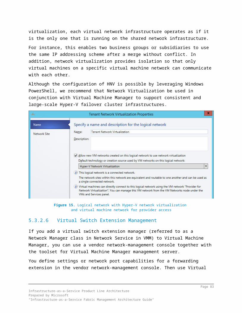
5.7.3.2 Capacity ManagementCapacity management defines the processes necessary to achieve the perception of infinite capacity. Capacity must be managed to meet existing and future peak demand while controlling underutilization. Business relationship and demand management are key inputs into effective capacity management and require a service provider’s approach. Predictability and optimization of resource usage are primary principles for achieving capacity management objectives.
5.7.3.3 Availability ManagementAvailability management defines processes necessary to achieve the perception of continuous availability. Continuity management defines how risks will be managed in a disaster scenario to help make sure minimum service levels are maintained. The principles of resiliency and automation are fundamental.
5.7.3.4 Service Level ManagementService-level management is the process of negotiating SLAs and making sure the agreements are met. SLAs define target levels for cost, quality, agility by service class, and the metrics for measuring actual performance. Managing SLAs is necessary to achieve the perception of infinite capacity and continuous availability. Service-level management also requires a service provider’s approach by IT.System Center 2012 R2 Operations Manager and System Center 2012 R2 Service Manager are used for measuring different kinds of service-level agreements.
5.7.3.5 Service Lifecycle ManagementService lifecycle management takes an end-to-end management view of a service. A typical journey starts by identifying a business need, then moves to managing a business relationship, and concludes when that service becomes available. Service strategy drives service design. After launch, the service is transitioned to operations and refined through continual service improvement. A service provider’s approach is critical to successful service lifecycle management. Processes like change, release, configuration and incident management are important processes that Service Manager supports in private cloud scenarios as outlined in the sections below.
5.8 Usage and BillingIT organizations are exploring chargeback as they become structured about how they deliver IT services to the business. Chargeback enables IT to show and cross-charge the business units that are consuming IT services.
Page 83Infrastructure-as-a-Service Product Line ArchitecturePrepared by Microsoft“Infrastructure-as-a-Service Fabric Management Architecture Guide"

With the availability of cloud computing in organizations, many consumers of IT services have the impression that IT has unlimited capacity and infinite resources. By introducing a chargeback model, IT can influence behavior and change the way its services are consumed.Potential improvements from chargeback include better utilization of the server infrastructure and reduction of costly services. The business also gets benefits from chargeback, such as the costs are predictable, and it could lead to changed behavior that encourages cost reductions by minimizing purchases.Chargeback is a part of financial management from the service delivery component of the ITIL Framework, and it delivers on the cloud attribute of transparency. For more information, see Installing and Configuring Chargeback Reports in System Center 2012 R2 - Service Manager.
5.8.1Chargeback vs. ShowbackAn alternative approach to chargeback is showback. Showback is used to show the business units the costs of the services they are consuming, without applying an actual cross-charge (internal bill). Showback can have the same effect as chargeback — to make the consumers of services aware of the related costs, to implement better usage of resources, and to limit the usage of unnecessary services. Chargeback and showback can be used to document the reasons for IT costs to leadership management.
5.8.2Developing a Chargeback ModelDefining the price of a virtual machine in a private or public cloud is a very cumbersome process that, depending on the ambition of the pricing, can take months to define. The price will be a combination of the operating expense and the capital expenditure.
Operating expense is the total cost of running the data center such as license costs, power, cooling, external consultants, insurance, and IT salaries. In some cases, the operating expense of a data center includes the costs of the services that IT employees use such as housing, human resources, and cafeterias.
Capital expenditure is the total cost when buying and upgrading physical assets such as servers, storage, and backup devices.
When the project has identified the operating expense and capital expenditure of a data center and multiplied it by the number of the servers, the end result should be a price per server. Unfortunately, it’s not that simple, because a virtual machine that depends on the specifications, applications, usage, and so on would ultimately mean a variable cost.
Page 84Infrastructure-as-a-Service Product Line ArchitecturePrepared by Microsoft“Infrastructure-as-a-Service Fabric Management Architecture Guide"

When looking at public pricing examples from major cloud service providers (for example, Windows Azure and Amazon), the cost of a virtual machine is a combination of the server type, hardware specifications, storage, and support agreement. The virtual machine is also charged per running hour. For additional details about these models, see the Windows Azure and the Amazon web services websites.
5.8.3System Center Chargeback CapabilitiesThe chargeback feature in Service Manager 2012 R2 is a combination of Virtual Machine Manager (VMM), Operations Manager, and Service Manager.In VMM, the Clouds are created and configured with resources, networks, templates, storage, capacity, and so on.In Operations Manager, several management packs needs to be imported, including the VMM management pack. Operations Manager then discovers and monitors the components of VMM, including the private clouds that are created in VMM.In Service Manager, several management packs need to be imported, including the VMM management pack. After the management packs are imported, an Operations Manager configuration item connector needs to be set up and configured to import cloud information into the CMDB. When the data is in the CMDB it is automatically transformed and moved the Service Manager Data Warehouse. For more information, see About Chargeback Reports in the System Center Library.The chargeback feature in Service Manager functions only when the connection between the System Center components is configured properly.
Figure 20. Components in System Center
5.9 Data Protection and Disaster RecoveryIn a virtualized data center, there are three commonly used backup types: host-based, guest-based, and a SAN-based snapshot. The following table contrasts these types.
Capability Host-Based
Guest-Based
SAN Snapshot
Page 85Infrastructure-as-a-Service Product Line ArchitecturePrepared by Microsoft“Infrastructure-as-a-Service Fabric Management Architecture Guide"

Protection of virtual machine configuration
× × *
Protection of host and cluster configuration
× × *
Protection of virtualization-specific data
× ×
Protection of data inside the virtual machine
× × ×
Protection of data inside the virtual machine stored on pass-through disks, iSCSI and vFC LUNs and Shared VHDx’es.
× ×
Support for Microsoft Volume Shadow Services (VSS)-based backups for supported operating systems and applications
× × × *
Support for continuous data protection × × × *
Ability to granularly recover specific files or applications inside the virtual machine
× × × *
* — Depends on storage vendor’s level of Hyper-V integrationTable 10. Backup comparisons
Page 86Infrastructure-as-a-Service Product Line ArchitecturePrepared by Microsoft“Infrastructure-as-a-Service Fabric Management Architecture Guide"

5.9.1Windows Azure BackupWindows Azure Backup provides an alternative to backing up System Center 2012 Data Protection Manager (DPM) to disk or to a secondary on premise DPM server. From System Center 2012 DPM onwards you can back up DPM servers and data protected by those servers to the cloud, using Windows Azure Backup.The fundamental workflow that you experience when you backup and restore files and folders to and from Windows Azure Backup are the same workflows that you would experience using any other type of backup. You identify the items to backup, and then the items are copied to storage where they can be used later if they are needed. Windows Azure Backup delivers business continuity benefits by providing a backup solution that requires no initial hardware costs other than a broadband Internet connection.There are two possible scenarios when running Windows Azure Backup — with and without System Center 2012 R2 Data Protection Manager, depending on the number of servers that need to be protected.
Figure 21. Windows Azure Backup Scenarios
Page 87Infrastructure-as-a-Service Product Line ArchitecturePrepared by Microsoft“Infrastructure-as-a-Service Fabric Management Architecture Guide"

5.9.2Data Protection ManagerSystem Center 2012 R2 Data Protection Manager allows disk-based and tape-based data protection and recovery for servers such as SQL Server, Exchange Server, SharePoint, Hyper-V servers, file servers, and support for Windows desktops and laptops. Data Protection Manager can also centrally manage system state and bare metal recovery. Data Protection Manager offers you a comprehensive solution when it comes to protecting your Hyper-V deployments.Supported scenarios include:
Protecting standalone or clustered computers running Hyper-V (CSVs and failover clusters are supported)
Protecting virtual machines Protecting a virtual machine that uses SMB storage Protecting Hyper-V with virtual machine mobility
When using Data Protection Manager for Hyper-V, you should be fully aware of and incorporate the recommendations for managing Hyper-V computers. For more information, see Managing Hyper-V Computers.Within the context of the guidance in this document, Data Protection Manager supports the protection of 800 virtual machines per Data Protection Manager Server. Given a maximum capacity of 8,000 virtual machines, Data Protection Manager would require 10 servers to ensure backup of the fully loaded Hyper-V Fabric.Data Protection Manager is aware of nodes within the cluster, and more importantly, aware of other Data Protection Manager servers. The installation of Data Protection Manager within a virtual machine is supported.The following six disk configurations are supported as Data Protection Manager storage pool.
Pass-through disk with direct attached storage to the host. Pass-through iSCSI LUN, which is attached to host. Pass-through Fibre Channel LUN, which is attached to host. iSCSI Target Server LUN, which is connected to a Data Protection Manager
virtual machine directly. Fibre Channel LUN, which is connected to a Data Protection Manager virtual
machine using Virtual Fibre Channel (vFC). Virtual Hard Disk drives (VHDx).
In the scenario outlined within this document, Data Protection Manager is protecting all data at the virtual machine level. As such, Data Protection Manager takes VSS snapshots of each virtual machine, based on the recovery timeline that is specified within the protection group. In this configuration, Data Protection Manager is able to recover the entire virtual machine to a point in time, and also recover individual file
Page 88Infrastructure-as-a-Service Product Line ArchitecturePrepared by Microsoft“Infrastructure-as-a-Service Fabric Management Architecture Guide"

level data from within a virtual machine without deploying an agent to each individual virtual machine.Individual file level data can be recovered (for example, C:\MyFile.txt); however, you cannot make application-aware backup or recovery operations. Thus for application workloads that Data Protection Manager typically protects (such as Exchange Server, SQL Server, or SharePoint), you should deploy an agent to individual virtual machines. These separate application profiles can place additional load on the Data Protection Manager servers, so you should use the guidance presented in this document to help account for disk space and overhead implications.The assumptions used for the sizing guidance of the Data Protection Manager servers in this document are based on the following.
The average virtual machine guest RAM size is 4 GB. The average virtual machine guest disk size is 50 GB. There is a daily churn rate of 10% per day per virtual machine. The Data Protection Manager server has at least a 1 GB network adapter. 800 Hyper-V guest virtual machines is the maximum that can be protected
per Data Protection Manager server.This requires that each Data Protection Manager server meets the following requirements:
37 GB of RAM (this is increased to 48 GB to allow for variation in deployments)
8 processor cores (the IaaS PLA assumes 6-8 cores per virtual CPU) In addition to the minimal storage space that is required to install the operating system and Data Protection Manager, there is a Data Protection Manager storage component that is related to the protected data. A minimum estimate for this storage is 1.5 times the size of the protected data for the virtual machine storage. However, a best practice deployment would provide a storage size of 2.5 to 3 times the baseline storage that is required for the Hyper-V virtual machines.The ultimate storage capacity will depend on the length of time the data is required to be kept and the frequency of the protection points. Additionally, protection for the Data Protection Manager server requires additional Data Protection Manager servers and storage capacity. For more information about storage capacity sizing estimates for Data Protection Manager, see Storage Calculators for System Center Data Protection Manager 2010 in the Microsoft Download Center. This information is also valid for System Center 2012 R2 Data Protection Manager.
5.9.3Hyper-V Recovery ManagerWindows Azure Hyper-V Recovery Manager (HRM) can help protect important services by coordinating the replication and recovery of virtual machines at a
Page 89Infrastructure-as-a-Service Product Line ArchitecturePrepared by Microsoft“Infrastructure-as-a-Service Fabric Management Architecture Guide"

secondary location. System Center 2012 R2 Virtual Machine Manager Clouds can be protected through automating the replication of the virtual machines that compose them at a secondary location.The ongoing asynchronous replication of each VM is provided by Windows Server 2012 R2 Hyper-V Replica and is monitored and coordinated by Hyper-V Recovery Manager.Hyper-V Recovery Manager monitors the state of Virtual Machine Manager clouds and also those in Windows Azure. Only the Virtual Machine Manager servers communicate directly with Windows Azure using outbound secure Web-based connection (utilizing TCP port 443). The data of the virtual machine and its replication always remains on premise.In addition, the service helps automate the orderly recovery in the event of a site outage at the primary data center. VMs can be brought up in an orchestrated fashion using “Recovery Plans” to help restore service quickly. An entire group of virtual machines can be restored, started in the right order and if needed additional scripts can be executed. This process can also be used for testing recovery, or temporarily transferring services. Note, the primary and recovery datacenter require independent Virtual Machine Manager management servers.
5.10 Consumer and Provider PortalAs discussed earlier, Windows Azure Pack is a collection of Windows Azure technologies that organizations can use to gain a Windows Azure-compatible experience within their own data centers. Windows Azure Pack provides a self-service portal for managing services such as websites, Virtual Machines and SQL databases. Although all Azure Pack components are not part of the IaaS PLA design, this section will briefly outline these capabilities.
5.10.1 Virtual Machine Role Service (VM Role)The VM Roles is an optional service that can be integrated to the Windows Azure Pack portal deployment. VM Role is an IaaS VM deployment service that enables either VM Templates or single tier VM Roles to be deployed in a self-service manner.To enable VM Role service, you must install the following components and integrate them into the WAP Admin portal.
Virtual Machine Manager (VMM) Service Provider Foundation (SPF) Service Management Automation Service Reporting
Page 90Infrastructure-as-a-Service Product Line ArchitecturePrepared by Microsoft“Infrastructure-as-a-Service Fabric Management Architecture Guide"

Once these components are installed, they must be integrated into the WAP solution using the WAP Service Management Admin Portal.
5.10.2 Windows Azure Pack Web Sites ServiceThe Windows Azure Pack Web Sites Service is an optional provider that can be integrated with the Windows Azure Pack to provide high speed, high density, self-service website creation from the Tenant portal in a PaaS-like model. Azure Website Service leverages the same PaaS website source that is running in the Windows Azure public cloud.The Windows Azure Pack Websites service uses a minimum of six server roles: Controller, Management Server, Front End, Web Worker, File Server, and Publisher in a distributed configuration to provide self-service websites.In addition, a SQL Server database for the Websites runtime database is required. These roles are separate from, and in addition to, the servers that form Windows Azure Pack installation. The roles can be installed on physical servers or virtual machines.
Figure 22. Windows Azure Pack Web Sites Service ComponentsThe Windows Azure Pack Web Sites service includes the following server roles.
Web Sites Controller. The controller provisions and manages the other Web Sites Roles.
Management Server. This server exposes a REST endpoint that handles management traffic to the Windows Azure Pack Websites Management API.
Page 91Infrastructure-as-a-Service Product Line ArchitecturePrepared by Microsoft“Infrastructure-as-a-Service Fabric Management Architecture Guide"

Web Workers. These are web servers that process client web requests. Web workers are either Shared or Reserved (at minimum, one of each is required) to provide differentiated levels of service to customers. Reserved workers are categorized into small, medium, and large sizes.
Front End. Accepts web requests from clients, routes requests to Web Workers, and returns web worker responses to clients. Front End servers are responsible for load balancing and SSL termination.
File Server. Provides file services for hosting web site content. The File Server houses all of the application files for every web site that runs on the Websites Service.
Publisher. Provides content publishing to the Web Sites farm for FTP clients, Visual Studio, and WebMatrix through the Web Deploy and FTP protocols.
5.10.3 SQL Tenant Database ServiceSQL Cloud Services is an optional service that can be provided to allow tenants to request SQL databases to be created on a shared SQL infrastructure.
5.10.4 MySQL Tenant Database ServiceMySQL Services is an optional service that can be provided to allow tenants to request MySQL databases to be created on a shared MySQL infrastructure.
5.11 Change ManagementChange management controls the lifecycle of all changes. The primary objective of change management is to eliminate, or at least minimize, disruption while desired changes are made to the services. Change management focuses on understanding and balancing the cost and risk of making the change versus the potential benefit of the change to the business or the service. Driving predictability and minimizing human involvement are the core principles for achieving a mature service management process and making sure changes can be made without impacting the perception of continuous availability.
5.11.1 Release and Deployment ManagementRelease and deployment management involves planning, scheduling, and controlling the build, test and deployment of releases, and delivering new functionality required by the business while protecting the integrity of existing services. Change management and release management hold a close relationship because releases consist of one or more changes.
Page 92Infrastructure-as-a-Service Product Line ArchitecturePrepared by Microsoft“Infrastructure-as-a-Service Fabric Management Architecture Guide"

5.11.2 Incident and Problem ManagementIncident management involves managing the lifecycle of all incidents. Incident management ensures that normal service operation is restored as quickly as possible and the business impact is minimized.Problem management is used to identify and resolve the root causes of incidents, and it involves managing the lifecycle of all problems. Problem management proactively prevents the same incidents from happening again and minimizes the impact of incidents that cannot be prevented.
5.11.3 Configuration ManagementConfiguration management helps ensure that the assets that are required to deliver services are properly controlled. The goal is to have accurate and effective information about those assets available when and where it is needed. This information includes details about asset configuration and the relationships between assets.Configuration management typically requires a CMDB, which is used to store configuration records throughout their lifecycles. The configuration management system maintains one or more CMDBs, and each CMDB stores attributes of configuration items and relationships to other configuration items.
5.12 Process AutomationThe orchestration layer that manages the automation and management components must be implemented as the interface between the IT organization and the infrastructure. Orchestration provides the bridge between IT business logic, such as “deploy a new web-server virtual machine when capacity reaches 85 percent”, and the dozens of steps in an automated workflow that are required to actually implement such a change.Ideally, the orchestration layer provides a graphical interface that combines complex workflows with events and activities across multiple management system components and forms an end-to-end IT business process. The orchestration layer must provide the ability to design, test, implement, and monitor these IT workflows.
5.12.1 Automation OptionsWith the release of Service Management Automation, Microsoft has introduced a new way for administrators and service providers to automate tasks in their environments. Rather than replace the existing graphical authoring environment
Page 93Infrastructure-as-a-Service Product Line ArchitecturePrepared by Microsoft“Infrastructure-as-a-Service Fabric Management Architecture Guide"

that is part of Orchestrator, SMA provides for a new layer of interoperability between the two automation engines.Service Management Automation integrates directly into Windows Azure Pack and allows for the automation of its core services (Web Sites, Virtual Machine Clouds, Service Bus, and SQL/MySQL).Orchestrator continues to build upon the use of Integration Packs to allow administrators to manage both Microsoft and non-Microsoft software and hardware endpoints.Deciding on whether to use SMA and Orchestrator runbooks separately or in unison should be based solely on the needs of the environment. Other key factors include available resources and skillsets among the team responsible for designing and supporting ongoing operations.With the proliferation of PowerShell in the majority of Microsoft and third-party workloads, SMA often lends itself as a more suitable management option. PowerShell provides greater flexibility than the activities built into Integration Packs. More specifically, PowerShell workflows allow for scalable automation sequences across multiple targets. SMA can also be used to initiate Orchestrator runbooks in turn.Those administrators who are more comfortable building their automation processes in a graphical manner can and should continue to use Orchestrator where it makes sense. Moreover, if integration with an existing 3rd-party solution is required, and Orchestrator Integration Pack is already available for that solution, this makes Orchestrator more preferable choice to build custom automation than SMA might be.
Page 94Infrastructure-as-a-Service Product Line ArchitecturePrepared by Microsoft“Infrastructure-as-a-Service Fabric Management Architecture Guide"

6 Service DeliveryAs the primary interface with the business, the service delivery layer is expected to know or obtain answers to the following questions:
What services does the business want? What level of service are business decision makers willing to pay for? How can a private cloud move IT from being a cost center to becoming a
strategic partner with the business?With these questions in mind, IT departments must address two main issues within the service layer:
How do we provide a cloud platform for business services that meets business objectives?
How do we adopt an easily understood, usage-based cost model that can be used to influence business decisions?
An organization must adopt the private cloud architecture principles to meet the business objectives of a cloud service.
Figure 23. Service delivery component of the Cloud Services Foundation Reference ModelThe components of the service delivery layer are:Financial management: Incorporates the functions and processes that are used to meet a service provider’s budgeting, accounting, metering, and charging requirements. The primary financial management concerns in a private cloud are providing cost transparency to the business and structuring a usage-based cost model for the consumer. Achieving these goals is a basic precursor to achieving the principle of encouraging desired consumer behavior.Demand management: Involves understanding and influencing customer demands for services, and includes the capacity to meet these demands. The principles of perceived infinite capacity and continuous availability are fundamental to stimulating customer demand for cloud-based services. A resilient, predictable environment with predictable capacity management is necessary to adhere to these principles. Cost, quality, and agility factors influence consumer demand for these services.Business relationship management: Provides the strategic interface between the business and IT. If an IT department is to adhere to the principle that it must act
Page 95Infrastructure-as-a-Service Product Line ArchitecturePrepared by Microsoft“Infrastructure-as-a-Service Fabric Management Architecture Guide"

as a service provider, mature business relationship management is critical. The business should define the functionality of required services and partner with the IT department on solution procurement. The business also needs to work closely with the IT department to define future capacity requirements to continue adhering to the principle of perceived infinite capacity.Service catalog: Presents a list of services or service classes that are offered and documented. This catalog describes each service class, eligibility requirements for each service class, service-level attributes, targets included with each service class (like availability targets), and cost models for each service class. The catalog must be managed over time to reflect changing business needs and objectives.Service lifecycle management: Provides an end-to-end management view of a service. A typical journey starts with identification of a business need, through business relationship management, to the time when that service becomes available. Service strategy drives service design. After launch, the service is transitioned to operations and refined through continual service improvement. Taking a service provider’s approach is critical to successful service lifecycle management.Service-level management: Provides a process for negotiating SLAs and making sure the agreements are met. SLAs define target levels for cost, quality, and agility by service class, in addition to metrics for measuring actual performance. Managing SLAs is necessary to achieve the perception of infinite capacity and continuous availability. This requires IT departments to implement a service provider’s approach.Continuity and availability management: Defines processes that are necessary to achieve the perception of continuous availability. Continuity management defines how risks will be managed in a disaster scenario to help make sure that minimum service levels are maintained. The principles of resiliency and automation are fundamental.Capacity management: Defines the processes necessary to achieve the perception of infinite capacity. Capacity must be managed to meet existing and future peak demand while controlling underutilization. Business relationship and demand management are key inputs into effective capacity management, and they require a service provider’s approach. Predictability and optimization of resource usage are primary principles in achieving capacity management objectives.Information security management: Strives to make sure that all requirements are met for confidentiality, integrity, and availability of the organization’s assets, information, data, and services. An organization’s particular information security policies drive the architecture, design, and operations of a private cloud. Resource segmentation and multitenancy requirements are important factors to consider during this process.
Page 96Infrastructure-as-a-Service Product Line ArchitecturePrepared by Microsoft“Infrastructure-as-a-Service Fabric Management Architecture Guide"

Page 97Infrastructure-as-a-Service Product Line ArchitecturePrepared by Microsoft“Infrastructure-as-a-Service Fabric Management Architecture Guide"

7 Service OperationsThe operations layer defines the operational processes and procedures necessary to deliver IT as a service. This layer uses IT service management concepts that can be found in prevailing best practice such as ITIL or MOF.The main focus of the operations layer is to carry out the business requirements that are defined at the service delivery layer. Cloud service attributes cannot be achieved through technology alone; mature IT service management is required.The operations capabilities are common to all three services: IaaS, platform as a service (PaaS), and software as a service (SaaS).
Figure 24. Service Operations component of the Cloud Services Foundation Reference ModelThe components of the operations layer include:Change management: Responsible for controlling the lifecycle of all changes. The primary objective is to implement beneficial changes with minimum disruption to the perception of continuous availability. Change management determines the cost and risk of making changes and balances them against the potential benefits to the business or service. Driving predictability and minimizing human involvement are the core principles behind a mature change management process.Service asset and configuration management: Maintains information about the assets, components, and infrastructure needed to provide a service. Accurate configuration data for each component and its relationship to other components must be captured and maintained. This data should include historical, current, and expected future states, and it should be easily available to those who need it.
Page 98Infrastructure-as-a-Service Product Line ArchitecturePrepared by Microsoft“Infrastructure-as-a-Service Fabric Management Architecture Guide"

Mature service asset and configuration management processes are necessary to achieve predictability.Release and deployment management: Ensures that changes to a service are built, tested, and deployed with minimal disruption to the service or production environment. Change management provides the approval mechanism (determining what will be changed and why), but release and deployment management is the mechanism for determining how changes are implemented. Driving predictability and minimizing human involvement in the release and deployment process are critical to achieving cost, quality, and agility goals.Knowledge management: Involves gathering, analyzing, storing, and sharing information within an organization. Mature knowledge management processes are necessary to achieve a service provider’s approach, and they are a key element of IT service management.Incident and problem management: Resolves disruptive, or potentially disruptive, events with maximum speed and minimum disruption. Problem management also identifies root causes of past incidents and seeks to identify and prevent, or minimize the impact of, future ones. In a private cloud, the resiliency of the infrastructure helps make sure that faults, when they occur, have minimal impact on service availability. Resilient design promotes rapid restoration of service continuity. Driving predictability and minimizing human involvement are necessary to achieve this resiliency.Request fulfillment: Manages user requests for services. As the IT department adopts a service provider’s approach, it should define available services in a service catalog based on business functionality. The catalog should encourage desired user behavior by exposing cost, quality, and agility factors to the user. Self-service portals, when appropriate, can assist the drive towards minimal human involvement.Access management: Denies access to unauthorized users while making sure that authorized users have access to needed services. Access management implements security policies that are defined by information security management at the service delivery layer. Maintaining smooth access for authorized users is critical to achieve the perception of continuous availability. Adopting a service provider’s approach to access management also ensures that resource segmentation and multitenancy are addressed.Systems Administration: Performs the daily, weekly, monthly, and as-needed tasks that are required for system health. A mature approach to systems administration is required for achieving a service provider’s approach and for driving predictability. The vast majority of systems administration tasks should be automated.
Page 99Infrastructure-as-a-Service Product Line ArchitecturePrepared by Microsoft“Infrastructure-as-a-Service Fabric Management Architecture Guide"
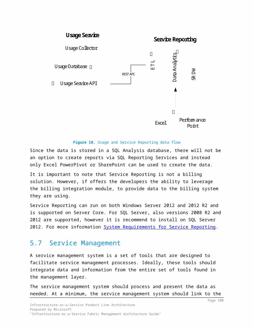
8 Disaster Recovery Considerations
8.1 OverviewDisaster recovery is an important element that must be considered in any deployment in order to minimize downtime and data loss in the event of a catastrophe. The decisions that are made in planning for disaster recovery affect how the Fabric Management components are deployed and how the cloud is managed. This section will focus on the overall strategy of disaster recovery and resiliency for a private cloud and what steps should be taken to ensure a smooth recovery. Individual product considerations and options can be found within the other sections in this document.Key functionality and capability of the Fabric Management system that should be evaluated for supporting disaster recovery scenarios includes:
Hyper-V Replica Multisite Failover Clusters Backup and Recovery SQL Server Always On
8.1.1Hyper-V ReplicaHyper-V Replica offers the ability periodically and asynchronously to replicate the virtual hard drives of a virtual machine to a separate Hyper-V host or cluster over a LAN or WAN link. After an initial replication is completed either over the network or by using physical media, incremental changes are synced over the network 30 seconds, 5 minutes or 15 minutes. Replica virtual machines can be brought up at any time in a planned failover or in the case of a disaster that takes the primary virtual machine offline. In the first case, there is no data loss: the primary and replica servers will sync all changes before switching. In the second case, there might be some data loss if changes have been made since the last replication. Hyper-V Replica is simple to set up and has the benefit of being storage- and hardware-agnostic. Physical servers do not have to be located near each other and do not have to be members of the same or any domain.Prerequisites for using Hyper-V Replica:
Hardware that supports the Hyper-V Role on Windows Server 2012 R2 Sufficient storage at the Primary and Secondary sites to store the virtual
disks attached to replicated virtual machines Network connectivity (LAN or WAN) between the Primary and Secondary sites Properly configured HTTP or HTTPS (if using Kerberos or certificate-based
authentication) listener in firewall on replica server or cluster
Page 100Infrastructure-as-a-Service Product Line ArchitecturePrepared by Microsoft“Infrastructure-as-a-Service Fabric Management Architecture Guide"

An X.509v3 certificate to support Mutual Authentication with certificates (if desired or needed)
8.1.2Multisite Failover ClustersAnother option for disaster recovery is to use a multisite failover cluster. This feature offers the ability to deploy a product for continuous availability across multiple sites. In this scenario, any shared data is replicated using third-party storage tools from a primary site’s cluster storage to a secondary site. In the event of a disaster, a highly available role fails over to nodes at the secondary site. The following figure shows a basic example of a four-node failover cluster stretched across two sites.
Figure 25. Multi-Site Failover ClusterIn the case of a disaster that takes the main site offline, the cluster storage at the secondary site will be switched to Read-Write, and cluster nodes at this site will begin hosting the clustered role. After the main site is up again, changes will be replicated to the main site’s storage, and the role can be failed over again.This is the recommended option for highly available Virtual Machine Manager installations and their library servers and is required for SQL Always-On Availability Groups that will span multiple sites. However, because Availability Groups and Virtual Machine Manager do not require shared storage, no third-party storage
Page 101Infrastructure-as-a-Service Product Line ArchitecturePrepared by Microsoft“Infrastructure-as-a-Service Fabric Management Architecture Guide"

replication would be required. Some components of System Center, such as the Reporting database in Operations Manager, are not compatible with Always On Availability Groups and should also utilize multisite failover clusters as a disaster recovery method. Multisite failover cluster instances with third-party storage replication can offer disaster recovery and high availability to these services in place of Availability Groups. It is recommended that the following components use multisite failover clusters:
Highly available Virtual Machine Manager installations Highly available file server SQL instances using SQL Always-On Availability Groups Highly available SQL instances that do not support Always-On Availability
Groups and leverage Always-On Failover Cluster Instances instead (such as the Operations Manager and Service Manager Reporting Databases)
8.1.3Backup and RestoreDesign guidance for data and system backup and restore that is specific to each System Center Component in the IaaS PLA can be found in the corresponding section of this document. While HA and DR solutions will provide protection from system failure or system loss, they should not be relied on for protection from accidental, unintended, or malicious data loss or corruption. In these cases, backup copies or lagged replication copies might have to be leveraged for restore operations.In many cases, a restore operation is the most appropriate form of disaster recovery. One example of this could be a low-priority reporting database or analysis data. In many cases, the cost to enable disaster recovery at the system or application level far outweighs the value of the data. In cases in which the near-term value of the data is low and the need to access the data can be delayed without severe business impact in the case of a failure or site recovery excessive, consider using simple backup and restore processes for disaster recovery if the cost savings warrant it.
8.2 Recovering from a DisasterIt also should be noted that there are few (if any) cases in which a site-recovery operation will take place for only the IaaS solution. The types of events that will commonly trigger a DR event include:
Failure of all or a very large number of the primary data center compute nodes for IaaS or service nodes for line-of-business (LOB) applications and services.
Complete or substantial failure of the primary data center storage infrastructure.
Page 102Infrastructure-as-a-Service Product Line ArchitecturePrepared by Microsoft“Infrastructure-as-a-Service Fabric Management Architecture Guide"

Complete or substantial failure or network outages that affect the entire primary data center.
Complete or substantial physical loss of the site or building that houses the primary data center.
Complete or substantial loss of local and remote access to the primary data center facility.
Before a DR operation to a recovery site is executed, a decision has to be made about whether the time and effort that it takes to recover the primary data center to a level of acceptable functionality is lower than the Recovery Time Objective (RTO) for a site failover. Additionally, the appropriate management personnel will need to account for the cost of returning to the primary data center at some point in the future. Exercises that simulate DR site failovers rarely reflect the actual disasters that trigger them or the circumstances that are unique to that disaster. All of these factors will come into play when management makes the decision to recover to a failover site.When considering site failure DR planning for System Center components in an IaaS solution, keep in mind that these components are generally of low business value in the near term. While the IaaS management capabilities are important to the long-term operations of the infrastructure that the business relies on, they will generally have functionality restored after other mission-critical and core business applications and services have been brought back online at the DR site.
8.3 Component Overview and Order of OperationsThe order in which System Center components of a cloud infrastructure are recovered after a disaster is dependent on the individual needs of the organization running them. One organization might place more importance on the ability to manage virtualization hosts and virtual machines by using Virtual Machine Manager, whereas another might care more about the ability to monitor its overall infrastructure by using Operations Manager with minimal interruption. Another might use Orchestrator to automate part of its disaster recovery efforts, in which case this would be the first component to bring up. Each organization should base its specific disaster recovery plan on its individual requirements and internal processes. The recommended order of operations in a typical disaster recovery, in which computers at the primary data center go down or lose connectivity, is as follows:
1. SQLservers should always be the first component to be brought online, because no System Center component will operate without its associated database. For more in-depth guidance, see the “SQL Always On” section in this document. If a database is part of an Always On Availability Group, the secondary
instance can be activated through SQL Management Studio. This is the Page 103
Infrastructure-as-a-Service Product Line ArchitecturePrepared by Microsoft“Infrastructure-as-a-Service Fabric Management Architecture Guide"
preferred method, where possible: it minimizes the potential for data loss and does not require third-party storage replication tools.
If the SQL virtual machine is replicated by using Hyper-V Replica, initiate a failover through Hyper-V Manager. This can result in some data loss: replication runs less often than the synchronization in an Availability Group.
If multisite failover clusters with third-party storage replication tools and without Availability Groups are used, storage at the secondary site will have to be enabled for read/write operations, and SQL roles will have to be failed over automatically or through failover cluster manager.
2. The next component to restore is the Virtual Machine Manager server, so that clusters, hosts, and virtual machines can be managed and monitored through the Virtual Machine Manager console. Note that Virtual Machine Manager will not be accessible until the Virtual Machine Manager database is available. Ensure that you are able to access the Virtual Machine Manager database through SQL Management Studio. The Virtual Machine Manager library also should be brought up, so that virtual machines can be provisioned by using stored templates. If PRO Tips are used, the Operations Manager Management Server might have to be reconfigured within Virtual Machine Manager. If you are using a highly available Virtual Machine Manager installation by
using multisite failover clustering (this is the recommended configuration), the role can be failed over automatically depending on the cluster configuration. If not, the role can be failed over manually to an available cluster node through failover cluster manager.
If the Virtual Machine Manager server is a stand-alone installation replicated by using Hyper-V Replica, bring up the replica virtual machine at the secondary site through Hyper-V Manager.
3. Operations Manager should be restored next to enable comprehensive monitoring of your environment. Ensure that the Operations Manager Operational Database is accessible through SQL Management Studio. In a typical recommended Operations Manager setup, standby
Management Servers should be ready at a secondary site to take over the monitoring workload from the primary Management Servers. In this case, Operations Manager agents will automatically begin reporting to these servers upon losing connection to the primary Management Servers.
If Hyper-V Replica is used to replicate Operations Manager servers to a secondary site, replica virtual machines should be brought online through Hyper-V Manager. Agents will see these replicas as if they were the same Management Servers and should continue operating as usual.
4. Orchestrator is the next component to restore. If your organization depends on automation for disaster recovery or for critical processes, it can be
Page 104Infrastructure-as-a-Service Product Line ArchitecturePrepared by Microsoft“Infrastructure-as-a-Service Fabric Management Architecture Guide"

brought up earlier. As with the other System Center components, ensure that the Orchestrator Database is accessible through SQL Management Studio. Hyper-V Replica is the recommended method for disaster recovery. This
will allow for replicas of the management and runbook servers to come up with no extra configuration. Enable the replica by using Hyper-V Manager.
If Hyper-V Replica is not a viable option for your organization, you can install one or more additional runbook servers at a secondary site. This option is less desirable: runbooks must be either reconfigured to run at the new site or designed to detect the site from which they are running.
5. Typically, Service Manager can be the last of the major components of System Center to be restored in a disaster; however, it can be brought up sooner if your organization’s requirements call for it. Ensure that the Service Manager database is accessible through SQL Management Studio. The Data Warehouse databases are less critical: they are used only for reporting purposes. The recommended option for disaster recovery is to keep a replica of the
primary Management Server at a secondary site by using Hyper-V Replica. In this scenario, use Hyper-V Manager to bring the replica server online.
Another option is to install an additional Management Server at a secondary site. In this scenario, the additional Management Server must be promoted to host the Workflow Initiator role. For more information, see the “Service Manager” section in this document.
8.4 Virtual Machine ManagerStandard disaster recovery (DR) preparations should be followed in all scenarios, including for Virtual Machine Manager. This includes scheduled, automated, and tested backup procedures, data redundancy, and attention paid to the level of DR capabilities required by an organization (because this can correlate to the extent of advance preparations and cost involved).As is the case with all of the System Center components, when a failure occurs that requires a rebuild or restoration of a specific component virtual machine, there are certain core steps that should be followed:
1. The computer account of the existing (failed) virtual machine should be removed from Active Directory Domain Services (AD DS).
2. The Domain Name System (DNS) record of the existing (failed) virtual machine should also be removed from the appropriate DNS zone. (This step might be optional if Dynamic DNS registration is in effect; however, removing the record will not have an adverse effect and can speed up the recovery procedures.)
Page 105Infrastructure-as-a-Service Product Line ArchitecturePrepared by Microsoft“Infrastructure-as-a-Service Fabric Management Architecture Guide"

3. If you are performing a rebuild, a replacement virtual machine should be provisioned by using the same computer account name as the original failed virtual machine.
4. If you are performing a rebuild, the IP address of the original failed virtual machine should also be reused as the IP address for the replacement virtual machine.
8.4.1Virtual Machine Manager Console RecoveryThe primary mechanism for Virtual Machine Manager Console recovery is prevention. As referenced in this document, a highly available Virtual Machine Manager implementation of a minimum of two Virtual Machine Manager Server virtual machines is required. In addition, a two-node (or greater) Fabric Management cluster is required to provide scale and availability of the Fabric Management workloads, including Virtual Machine Manager. Another benefit of deploying a highly available Virtual Machine Manager implementation is the requirement to use distributed key management (DKM), thus storing the Virtual Machine Manager encryption key in AD DS. This mitigates the need to separately ensure the availability and restoration of this key in a DR scenario. In the case of a loss of a Virtual Machine Manager server virtual machine in a highly available Virtual Machine Manager implementation, the recommended recovery approach is the following.
Scenario SQL State VMM Library State
Recovery Steps
Active HA VMM server crashes
SQL continues to run Virtual Machine Manager Library continues to run
The highly available architecture of Virtual Machine Manager will enable another Virtual Machine Manager server instance to pick up and resume normal operating capabilities.
HA VMM server crashes and cannot fail over; good backup is available
SQL continues to run Virtual Machine Manager Library continues to run
Recover the failed Virtual Machine Manager from a valid backup source.
HA VMM server crashes and cannot fail over; no good backup is available
SQL continues to run Virtual Machine Manager Library continues to run
Reinstall the Virtual Machine Manager server, leveraging the existing SQL Server database and DKM data from AD DS.Re-associate hosts that have a status of Access Denied in the Virtual Machine Manager console.
Barring the preceding, there might be an organizational need or architectural desire to deploy Virtual Machine Manager in a stand-alone configuration. An example of this would be to leverage Hyper-V Replica as part of a multisite deployment and business continuity/disaster recovery (BC/DR) approach. This is not the required or recommended approach as it introduces an increased exposure for loss of a Virtual
Page 106Infrastructure-as-a-Service Product Line ArchitecturePrepared by Microsoft“Infrastructure-as-a-Service Fabric Management Architecture Guide"

Machine Manager stand-alone implementation. In this case, it is still strongly recommended to implement a DKM approach (even for a stand-alone Virtual Machine Manager server) since this mitigates the need to have backups of the DKM key separate from the stand-alone server. In the case of a loss of a Virtual Machine Manager server virtual machine in a stand-alone Virtual Machine Manager implementation, the recommended recovery approach is the following.
Scenario SQL State
VMM Library State
DKM?
Recovery Steps
Single VMM server crashes; good backup is available
SQL continues to run
Virtual Machine Manager Library continues to run.
Either. Recover the failed Virtual Machine Manager from a valid backup source.
Single VMM server crashes; no good backup is available
SQL continues to run
Virtual Machine Manager Library continues to run.
Yes. Reinstall the Virtual Machine Manager server, leveraging the existing SQL Server database and DKM data from AD DS.Re-associate hosts that have a status of Access Denied in the Virtual Machine Manager console.Re-create all other required connections (such as the Operation Manager Server configuration).
Single VMM server crashes; no good backup is available
SQL continues to run
Virtual Machine Manager Library continues to run.
No. Reinstall the Virtual Machine Manager server, leveraging the existing SQL Server database and DKM data from AD DS.Restore the DKM key from a backup source.Re-associate hosts that have a status of Access Denied in the Virtual Machine Manager console.Re-create all other required connections (such as the Operation Manager Server configuration).
8.4.2SQL Server RecoveryAs with Virtual Machine Manager Console recovery, the primary mechanism for SQL Server recovery (specific to the Virtual Machine Manager database and contents) is prevention. As discussed earlier, a minimum of two highly available SQL Server virtual machines must be deployed as a failover cluster to support failover and availability. However, there can be situations in which the actual storage location for the databases and logs can be affected negatively. In these cases, a restoration from known good backup sources will be required. It is important to follow standard SQL Server database recovery procedures—restoring the SQL Server master and
Page 107Infrastructure-as-a-Service Product Line ArchitecturePrepared by Microsoft“Infrastructure-as-a-Service Fabric Management Architecture Guide"

MSDB databases first, and then proceeding to the specific databases for that SQL instance, as appropriate. The Virtual Machine Manager database is a SQL Server database that contains Virtual Machine Manager configuration information and it is recommended that database be backed up regularly. To restore the Virtual Machine Manager database, you can use the SCVMMRecover.exe tool that is available on the Virtual Machine Manager Management Server.
Note that SCVMMRecover.exe cannot be used to recover a Virtual Machine Manager database that is used by a highly available Virtual Machine Manager Management Server. Instead, you must use tools provided by SQL Server to back up and restore the Virtual Machine Manager database.
After the Virtual Machine Manager database has been recovered, you will need to do the following:
1. Add or remove any hosts that were added or removed from Virtual Machine Manager since the last backup. If a host has been removed since the last backup, the host will have a status of Needs Attention in the Virtual Machine Manager console. Any virtual machines on that host will have a status of Host Not Responding.
2. Remove any virtual machines that were removed from Virtual Machine Manager since the last backup. If a host has a virtual machine that was removed since the last backup, the virtual machine will have a status of Missing in the Virtual Machine Manager console.
3. If you restored the Virtual Machine Manager database to a different computer, re-associate hosts that have a status of Access Denied in the Virtual Machine Manager console.: A computer is considered different if it has a different security identifier (SID). For example, if you reinstall the operating system on the computer, the computer will have a different SID, even if you use the same computer name.
4. You also will have to perform similar actions for library servers in your environment.
8.4.3Library Server RecoveryIn a highly available Virtual Machine Manager implementation, the Virtual Machine Manager Library must also reside outside of the Virtual Machine Manager Cluster itself. This requirement supports the loss of either the Virtual Machine Manager Cluster or the Virtual Machine Manager Library itself by reducing the impact to the environment because of the separation of these key resources.As discussed in this document, the Virtual Machine Manager Library should be deployed in a highly available manner through the use of a separate file-server cluster. Again, standard DR prevention procedures apply: having adequate scheduled, automated, and tested backup procedures in place, duplication or redundancy of backup media, and multisite storage of said backups.
Page 108Infrastructure-as-a-Service Product Line ArchitecturePrepared by Microsoft“Infrastructure-as-a-Service Fabric Management Architecture Guide"

Scenario SQL State
VMM Server State
Recovery Steps
Single VMM Library server crashes; good backup is available
SQL continues to run
VMM Server continues to run
Recover the failed VMM Library from a valid backup source.
Single VMM Library server crashes; no good backup is available
SQL continues to run
VMM Server continues to run
All Library content (ISOs, VHDX, scripts, and so on) must be repopulated or re-created.
Active node of HA VMM Library server crashes
SQL continues to run
VMM Server continues to run
The Library content and function will fail over to a remaining node of the HA file-server cluster.
8.4.4Integration Point RecoveryAs mentioned earlier, there are several additional points of integration within a complete Virtual Machine Manager implementation. These integration points include PXE servers, Windows Server Update Services (WSUS) servers and connectors to other System Center components. The following section specifically addresses recovery procedures and requirements for these elements.
Distributed Key ManagementThe requirement for implementing DKM for Virtual Machine Manager mitigates the need to separately ensure the availability and restoration of this key in a DR scenario. This is consistent for single-site or multisite implementations.
Bare-Metal ProvisioningIf lost, the PXE Server supporting a Virtual Machine Manager site implementation must be restored using standard file-server recovery procedures, leveraging a known good backup source. In a multisite configuration, a PXE server must be deployed at every site at which bare-metal provisioning is required. This increases the planning and effort that are required to recovery from a disaster scenario, because the preceding backup and recovery procedures and requirements must be implemented at each separate location. After recovery, each PXE server may require to be re-registered with the Virtual Machine Manager Management Server
Page 109Infrastructure-as-a-Service Product Line ArchitecturePrepared by Microsoft“Infrastructure-as-a-Service Fabric Management Architecture Guide"

by using the administrative console, although this is dependent on the state and availability of the Virtual Machine Manager DKM master key and the Virtual Machine Manager SQL Server database.
Update Server IntegrationIf a WSUS server is lost, it must also be recovered by using a similar approach as previously described for a PXE server. However, there are two separate procedures for recovering WSUS data: recovering the WSUS database, and restoring the WSUS update files (if they were chosen for backup initially).
To restore the WSUS update files, copy the backup files to the %systemdrive%\WSUS\WSUSContent folder on your WSUS server.
To restore the WSUS database, follow standard SQL Server database recovery procedures—restoring the master and MSDB databases first, and then proceeding to the specific database(s) for that SQL instance (in this case, the WSUS database).
Operations Manager IntegrationImpact to the Operations Manager configuration within the Virtual Machine Manager Console or Management Server is negligible with the loss of the Virtual Machine Manager Management Server since this configuration is stored in the SQL Server database configuration. Should the Virtual Machine Manager SQL database be lost (unrecoverable), this connection or configuration will have to be re-created after recovery or rebuild of the Virtual Machine Manager Management Server. This is consistent for single-site or multisite implementations. If the Operations Manager server or management group is lost or affected, standard Operations Manager recovery procedures should be followed.
VMware vCenter Server IntegrationImpact to the VMware vCenter Server configuration within the Virtual Machine Manager Console or Management Server is negligible with the loss of the VMM Management Server, because this configuration is stored in the SQL Server database configuration. If the vCenter server becomes unavailable, you must reestablish a connection to a new vCenter server. This is consistent for single-site or multisite implementations. There is no support for VMware vCenter Server Heartbeat or for a standby vCenter server.Recovery procedures for a loss of a vCenter server should always be referenced from the vendor (VMware).
Page 110Infrastructure-as-a-Service Product Line ArchitecturePrepared by Microsoft“Infrastructure-as-a-Service Fabric Management Architecture Guide"

Connector IntegrationImpact to the Orchestrator, App Controller and Service Manager Virtual Machine Manager connector configurations are negligible with the loss of the Virtual Machine Manager Management Server, because the configuration of the connectors are performed within Orchestrator, App Controller and Service Manager, then stored in the SQL Server database configuration of each component. Restoration of the Virtual Machine Manager Management Server should follow the previously provided guidance (including reusing the previous Virtual Machine Manager computer account name, since this is leveraged by these components for the connector). This is consistent for single-site or multisite implementations. However, in a multisite configuration in which a stand-alone Virtual Machine Manager instance is being protected via Hyper-V Replica and a failover occurs, the connection to Virtual Machine Manager will be affected until the component servers have received the updated IP address for the secondary Virtual Machine Manager instance. If the Service Manager Management Server, App Controller or Orchestrator Runbook/Management Server is lost or otherwise affected, standard recovery procedures should be followed for these components.
8.5 Operations ManagerWith System Center 2012 R2 Operations Manager, all of the SDK services of a Management Server are able to run at the same time. This allows any SDK client to connect to any Management Server for access. Prior to the removal of the Root Management Server (RMS) role, most third-party applications or other Operations Manager components were bound to the RMS for SDK-related access. Failure of the RMS will result in the subsequent failures of all dependent applications.The following components and applications that depend directly on the availability of the SDK service:
Operations Manager components Web Console Server Operations Manager Console Report Server
System Center components System Center Orchestrator System Center Virtual Machine Manager System Center Service Manager
Operations Manager supports configuring the data-access service for high availability. This can be achieved through load balancing of the Management Servers. In the event that the current connection to the Management Server fails,
Page 111Infrastructure-as-a-Service Product Line ArchitecturePrepared by Microsoft“Infrastructure-as-a-Service Fabric Management Architecture Guide"
subsequent connections can be re-established to the remaining active Management Servers.The following components depend on a one-to-one relationship with a specific Management Server. Failure of the Management Server will result in failure of the paired component.
System Center Orchestrator Reporting Server System Center Virtual Machine manager System Center Service Manager Web Console Server (only applicable in scenarios where the role separately
from the management server)
8.5.1Hyper-V Replica and Operations ManagerLeveraging Hyper-V replica is a viable DR option for Operations Manager. However, it will change the overall DR plan. The following changes will occur from using Hyper-V Replica:
There is no need for standby Management Servers: the primary Management Servers will be copied, and identity will be retained (only with whatever delay occurs from bringing the replicated servers online). Agents should be able to resume communications with the System Center Operations Manager infrastructure.
The use of a SQL Server Always On Availability Group or log shipping as a viable database recovery plan is required.
8.5.2Audit Collection Service Disaster Recovery ConsiderationsThe Operations Manager Audit Collection Services (ACS) collector is one of two points of failures when implementing Operations Manager ACS. You do have the ability to deploy two collectors that point to the same ACS database by configuring them in active/passive mode. Please see the following guide about configuring your ACS collector in active/passive mode.
Note, while the guide above refers to Operations Manager 2007 SP1, it still valid for Operations Manager 2012 R2.
8.5.3Gateway Disaster Recovery ConsiderationsThere are two failure points to consider in Gateway DR scenarios. The first scenario covers the failure point between the gateway and the Management Server with which it is paired during initial gateway configuration. When the Management Server fails, the gateway will be unable to send any data back to the management group.
Page 112Infrastructure-as-a-Service Product Line ArchitecturePrepared by Microsoft“Infrastructure-as-a-Service Fabric Management Architecture Guide"

The second is ensuring that the gateway server’s agents have a failover server on which to fall back. The first scenario is generally handled through the Management Server failover list of the configuring gateway server. The second is handled through the deployment of additional gateways and configuring the failover list of the agent gateway.
8.5.4SQL Database Instances Disaster Recovery ConsiderationsOne of the critical areas of availability within Operations Manager is the database component. Before the introduction of SQL Server 2012 Always On, Operations Manager Administrators had to resort to numerous means of restoring the database to the secondary site. SQL Server 2012 Always On provides an alternate disaster recovery option besides SQL Server log shipping or geo-clustering. Log shipping provides redundancy to the Operations Manager database between two SQL servers. The primary SQL server would be situated at the primary site and the secondary with the secondary failover site. Geo-clustering enables the ability to extend database presence to a secondary site. Setting up a SQL cluster in active/passive mode (with the passive node on the secondary site) will reduce the downtime in the event that the primary database server fails. This avoids the manual step of reconfiguring Operations Manager to communicate with the new database server.
8.5.5Web Console Disaster Recovery ConsiderationsThe following components have dependencies on the Web Console role:
SharePoint Web part Web Console Client connections APM monitoring consoles
To achieve high availability in a multisite context, at least two web console servers must be deployed. For disaster recovery scenarios, the web console roles should be merged with the standby Management Server roles to reduce resource requirements.
8.6 OrchestratorFor availability within Orchestrator is important to design a solution that ensures the availability of runbooks both within the data center and across data centers. The overall solution must also include options that will allow for recovery of Orchestrator in the event of an application, system, or complete site failure. This section includes various options that can be used to meet these requirements.
Page 113Infrastructure-as-a-Service Product Line ArchitecturePrepared by Microsoft“Infrastructure-as-a-Service Fabric Management Architecture Guide"

8.6.1Single-Site Deployment with Hyper-V ReplicaThe two areas which introduce complexity in a multisite design of Orchestrator include latency and multiple management servers. Networks which segment data centers are typically not sufficient for maintaining low latency connections, thus resulting in poor runbook performance. A design that spans sites, while possible, might not be the most practical in many situations in which an organization’s IT infrastructure is heavily dependent on automation.With Windows Server 2012 R2 Hyper-V Replica, it is much easier to incorporate a disaster recovery solution into an Orchestrator deployment. By installing the components of Orchestrator on one or more virtual machines that are configured for Hyper-V Replica, an organization can execute a failover in the event that a disaster occurs at the primary site. Since all of the settings of a virtual machine and its guest operating system remain intact using Hyper-V Replica, Orchestrator can be brought online at a secondary site with minimal overhead. Hyper-V Replica can also be used to replicate a virtual machine running an instance of SQL server. By installing the Orchestrator database on an instance configured for Hyper-V Replica, the state of the database can be recovered along with the remaining Orchestrator components.
8.6.2Runbook Design ConsiderationsIf a single-site solution is chosen for Orchestrator, the design of each runbook must incorporate activities that will ensure continued execution upon a planned failover. Not only must the state of a runbook be considered, but a runbook must also be aware of the environment under which it is running. There are a few ways in which a runbook can be configured for both state and site awareness. A runbook can write information about itself to a temporary log that is subsequently stored in a table or database. This information can include the latest running activity, the runbook server on which it is running, and any additional generated events.For example, a runbook that performs some management tasks on network switches at the primary data center should perform the same tasks at the secondary data center in the event of a failover. When such an event occurs, the runbook can be configured to detect automatically which site it resides on and initiate the execution of a duplicate runbook configured for the secondary data center.
8.6.3Database Resiliency with SQL Always On Availability GroupsThe preferred method for ensuring Orchestrator database resiliency across sites is to utilize SQL Always On Availability Groups. With System Center 2012 R2, Orchestrator can be installed by using a previously configured Availability Group Listener rather than a single instance name. This allows Orchestrator to continue
Page 114Infrastructure-as-a-Service Product Line ArchitecturePrepared by Microsoft“Infrastructure-as-a-Service Fabric Management Architecture Guide"

communicating with its database in the event a SQL failover is initiated between sites.
8.6.4Disaster Recovery of Orchestrator Using Data Protection Manager
Regardless of which solution is used to deploy Orchestrator, it is important to consider how the components will be backed up. As described earlier, maintaining two distinct Orchestrator environments would require a rebuild of one of the sites in the event of a failure. To minimize the amount of work involved in doing so, an organization can choose to implement a method of backing up their deployment of Orchestrator. Data Protection Manager can be used to protect everything from an individual application’s configuration to an entire virtual machine. The level at which Orchestrator is to be recovered also plays a role in how it should be backed up.It is recommended that a complete backup of an Orchestrator environment include the database, file backup of the Management Server, and file backup of each runbook and web server. Furthermore, a Data Protection Manager agent should be installed on each virtual machine that is running a component of Orchestrator, so that the state of the guest operating system can be protected.Restoration of an Orchestrator environment in a disaster recovery situation requires a restore of the SQL service master key along with its respective database. When restoring the database onto a different instance of SQL, the DBSetup utility can be used to change the instance that is used by the Management Server or runbook servers to connect to the database.
8.7 Service ManagerWhen designing the disaster recovery procedures for Service Manager, the following is the order of the recovery (in case of full recovery):
1. Service Manager database2. Service Manager Management Server (Workflow Initiator)3. Service Manager Management Server (Console Access)4. Service Manager portal (Web Content and SharePoint)5. Service Manager Data Warehouse databases6. Service Manager Data Warehouse Management Server
8.7.1Service Manager DatabasesRegardless of whether the Service Manager databases are configured as part of a Failover SQL Cluster or a SQL Server Always On Availability Group, both solutions would fail over seamlessly to the redundant site (if they are configured accordingly), seen from the rest of the Service Manager environment. A Service Manager
Page 115Infrastructure-as-a-Service Product Line ArchitecturePrepared by Microsoft“Infrastructure-as-a-Service Fabric Management Architecture Guide"

database restore requires a server that has the same computer name and instance name as the original SQL Server.
8.7.2Workflow Initiator RoleThe Management Server which has the Workflow Initiator role is the most critical Management Server in the Service Manager infrastructure. There are several options available to restore the functionality of the server. During periods of workflow initiator unavailability, no workflows will execute. This will therefore affect notifications, queue updates, and other dependent Service Manager operations. When determining service level targets, it is important to determine the organizational tolerance to having workflows disabled and decide on a disaster recovery strategy that balances cost and complexity.
8.7.3Management Server Console AccessFor larger environments where analysts access the Service Manager console simultaneously, it is recommended to place several secondary Management Servers in a load balanced configuration. This provides users with a single address to use in the settings of the Service Manager console, regardless of how many Management Servers are supporting console access. If the console access is considered critical and time does not permit a Management Server to be reinstalled or restored, it is an option to place some secondary Management Servers on the failover site, leaving inactive or active, depending on network connectivity or latency, or alternatively use Hyper-V Replica.
8.7.4Service Manager ConnectorsIn the case of a site failover of any of the components with which Service Manager interacts, it is important to plan DR procedures. Service Manager has connectors that can pull information from Operations Manager, Configuration Manager, Virtual Machine Manager, Orchestrator, Exchange, and AD DS. This section covers how to handle the failure of the components on which Service Manager depends.
8.7.4.1 Operations Manager ConnectorWhen you are configuring the Operations Manager connector, you must configure it to an Operations Manager Management Server that is hosting the Operations Manager RMS emulator role. Depending on the disaster recovery procedures for the Operations Manager and on whether or not the RMS emulator role must be moved, the connector might or might not have to be reconfigured.
Page 116Infrastructure-as-a-Service Product Line ArchitecturePrepared by Microsoft“Infrastructure-as-a-Service Fabric Management Architecture Guide"
8.7.4.2 Configuration Manager ConnectorThe Configuration Manager connector is configured by configuring a SQL server that holds the Configuration Manager database. If the Configuration Manager database is available at the failover site, the Configuration Manager connector will be functional after a failover.
8.7.4.3 Virtual Machine Manager ConnectorThe Virtual Machine Manager Connector is configured by configuring it to use the Virtual Machine Manager Server. Once configured, objects such as virtual machine templates, service templates, and storage classifications are imported. To ensure the functionality of the Virtual Machine Manager connector, best option is to ensure the Virtual Machine Manager server always use the same name, also in case of the site failover. If the Virtual Machine Manager server role must be transferred to another server, the Virtual Machine Manager Connector must be reconfigured, or a new one must be created.
8.7.4.4 Orchestrator ConnectorThe Orchestrator connector is configured by configuring it to use the Orchestrator Web service. To ensure functionality during a site failover, consider the following options:
Configure a second Orchestrator connector to point to an alternative Orchestrator web service. As long as the same runbooks are present on both web services, Service Manager will be able to initialize them during a request.
Creation of a DNS record, configure an IP that points to an Orchestrator Web Service, and—in case of an Orchestrator failover—change the DNS record to point to a functional Orchestrator Web Service.
8.7.4.5 Active Directory ConnectorThe Service Manager Active Directory Connector pulls information from the first available Domain controller; therefore, it will function as long as the Service Manager can connect to a Domain Controller.
Page 117Infrastructure-as-a-Service Product Line ArchitecturePrepared by Microsoft“Infrastructure-as-a-Service Fabric Management Architecture Guide"

9 Security ConsiderationsThe three pillars of IT security are confidentiality, integrity, and availability. IT infrastructure threat modeling is the practice of considering what attacks might be attempted against the components in an IT infrastructure. Generally, threat modeling assumes the following conditions:
Organizations have resources (in this case, IT components) that they wish to protect
All resources are likely to exhibit some vulnerability People might exploit these vulnerabilities to cause damage or gain
unauthorized access to information Properly applied security countermeasures help mitigate threats that exist
because of vulnerabilitiesThe IT infrastructure threat modeling process is a systematic analysis of IT components that compiles component information into profiles. The goal of the process is to develop a threat model portfolio, which is a collection of component profiles.One way to establish these pillars as a basis for threat modeling IT infrastructure is through MOF, which provides practical guidance for managing IT practices and activities throughout the entire IT lifecycle.The effective service management function (SMF) in the Plan phase of the MOF addresses creating plans for confidentiality, integrity, availability, continuity, and capacity. The policy SMF in the Plan phase provides context to help understand the reasons for policies, their creation, validation, and enforcement, and it includes processes to communicate policies, incorporate feedback, and help IT maintain compliance with directives. For more information, see:
Reliability Service Management Function Policy Service Management Function
The Deliver phase contains several SMFs that help make sure project planning, solution building, and the final release of the solution are accomplished in ways that fulfill requirements and create a solution that is fully supportable and maintainable when operating in production.
Page 118Infrastructure-as-a-Service Product Line ArchitecturePrepared by Microsoft“Infrastructure-as-a-Service Fabric Management Architecture Guide"

Figure 26. Threat prioritization according to a series of parametersFor more information, see
IT Infrastructure Threat Modeling Guide Security Risk Management Guide
Security for Microsoft private clouds is founded on three pillars: protected infrastructure, application access, and network access.
9.1 Protected InfrastructureA defense-in-depth strategy is utilized at each layer of the Microsoft private cloud architecture. Security technologies and controls must be coordinated. Compromise of the Fabric Management infrastructure can lead to total compromise of the private cloud environment. As such, significant effort needs to go into protecting it.An entry point represents data or process flow that crosses a trust boundary. Any portions of an IT infrastructure in which data or processes cross from a less-trusted zone into a more-trusted zone should have a higher review priority.Users, processes, and IT components operate at specific trust levels that vary between fully trusted and fully untrusted. Typically, parity exists between the level of trust that is assigned to a user, process, or IT component and the level of trust that is associated with the zone in which the user, process, or component resides.Malicious software poses numerous threats to organizations, from intercepting a user's logon credentials with a keystroke logger to achieving complete control over a computer or an entire network by using a rootkit. Malicious software can cause websites to become inaccessible, destroy or corrupt data, and reformat hard disks.
Page 119Infrastructure-as-a-Service Product Line ArchitecturePrepared by Microsoft“Infrastructure-as-a-Service Fabric Management Architecture Guide"

Effects can include additional costs such as to disinfect computers, restore files, re-enter, or re-create lost data. Virus attacks can also cause project teams to miss deadlines, leading to breach of contract or loss of customer confidence. Organizations that are subject to regulatory compliance can be prosecuted and fined.A defense-in-depth strategy, with overlapping layers of security, is a strong way to counter these threats. The least-privileged user account approach is an important part of that defensive strategy. The least-privileged user account approach directs users to follow the principle of least privilege and log on with limited user accounts. This strategy also aims to limit the use of administrative credentials to administrators for administrative tasks only.
9.2 Application AccessAD DS provides the means to manage the identities and relationships that make up a Microsoft private cloud. Integrated in Windows Server 2012 and Windows Server 2008 R2, AD DS provides the functionality that is needed to centrally configure and administer system, user, and application settings.Windows Identity Foundation allows .NET developers to externalize identity logic from their application, which improves developer productivity, enhances application security, and allows interoperability. Developers can enjoy greater productivity while applying the same tools and programming model to build on-premises software and cloud services. Developers can create more secure applications by reducing custom implementations and by using a single simplified identity model, based on claims.
9.3 Network AccessWindows Firewall with Advanced Security combines a host firewall and Internet Protocol Security (IPsec). Unlike a perimeter firewall, Windows Firewall with Advanced Security runs on each computer, and provides local defense from network attacks that might pass through your perimeter network or originate inside your organization. It also contributes to computer-to-computer connection security by allowing you to require authentication and data protection for communications.You can also logically isolate server and domain resources to limit access to authenticated and authorized computers. You can create a logical network inside an existing physical network in which computers share a common set of requirements for more secure communications. To establish connectivity, each computer in the logically isolated network must provide authentication credentials to other computers in the isolated network to prevent unauthorized computers and
Page 120Infrastructure-as-a-Service Product Line ArchitecturePrepared by Microsoft“Infrastructure-as-a-Service Fabric Management Architecture Guide"
programs from gaining access to resources inappropriately. Requests from computers that are not part of the isolated network are ignored.
9.4 System Center Endpoint ProtectionDesktop management and security have traditionally existed as two separate disciplines, yet both play central roles in helping to keep users safe and productive. Management provides proper system configuration, deploys patches against vulnerabilities, and delivers necessary security updates. Security provides critical threat detection, incident response, and remediation of system infection.Endpoint Protection in System Center 2012 R2 (formerly known as Forefront Endpoint Protection) aligns these two work streams into a single infrastructure. Endpoint Protection uses the following key features to help protect critical desktop and server operating systems against viruses, spyware, rootkits, and other threats: Single console to manage and secure Endpoint Protection: Configuration Manager (not included as part of this solution) provides a single interface for managing and securing desktops that reduces complexity and improves troubleshooting and reporting insights. As an alternative, the System Center Security Management Pack for Endpoint Protection (SCEP) in Operations Manager can be used for monitoring in conjunction with a provided Group Policy administrative template for management. Central policy creation: Administrators have a central location for creating and applying all client-related policies. Enterprise scalability: Use of the Configuration Manager infrastructure makes it possible to efficiently deploy clients and policies in large organizations around the globe. By using Configuration Manager distribution points and an automatic software deployment model, organizations can quickly deploy updates without relying on WSUS. Highly accurate and efficient threat detection: The antimalware engine helps protect against the latest malware and rootkits with a low false-positive rate, and helps keep employees productive by using scanning that has a low impact on performance. Behavioral threat detection: System behavior and file reputation data identify and block attacks on client systems from previously unknown threats. Detection methods include behavior monitoring, the cloud-based dynamic signature service, and dynamic translation. Vulnerability shielding: Helps prevent exploitation of endpoint vulnerabilities with deep protocol analysis of network traffic.
Page 121Infrastructure-as-a-Service Product Line ArchitecturePrepared by Microsoft“Infrastructure-as-a-Service Fabric Management Architecture Guide"
Automated agent replacement: Automatically detects and removes common endpoint security agents to lower the time and effort needed to deploy new protection. Windows Firewall management: Ensures that Windows Firewall is active and working properly to help protect against network-layer threats. It also allows administrators to more easily manage protection across the environment.
Page 122Infrastructure-as-a-Service Product Line ArchitecturePrepared by Microsoft“Infrastructure-as-a-Service Fabric Management Architecture Guide"

10 Appendix A: Detailed SQL Server Design Diagram
Page 123Infrastructure-as-a-Service Product Line ArchitecturePrepared by Microsoft“Infrastructure-as-a-Service Fabric Management Architecture Guide"

11 Appendix B: System Center Connections
Page 124Infrastructure-as-a-Service Product Line ArchitecturePrepared by Microsoft“Infrastructure-as-a-Service Fabric Management Architecture Guide"