11,12. 46-121.pdf
TRANSCRIPT
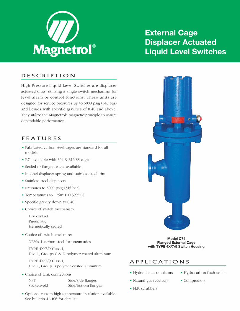
D E S C R I P T I O N
High Pressure Liquid Level Switches are displacer
actuated units, utilizing a single switch mechanism for
level alarm or control functions. These units are
designed for service pressures up to 5000 psig (345 bar)
and liquids with specific gravities of 0.40 and above.
They utilize the Magnetrol® magnetic principle to assure
dependable performance.
F E A T U R E S
• Fabricated carbon steel cages are standard for allmodels.
• B74 available with 304 & 316 SS cages
• Sealed or flanged cages available
• Inconel displacer spring and stainless steel trim
• Stainless steel displacers
• Pressures to 5000 psig (345 bar)
• Temperatures to +750° F (+399° C)
• Specific gravity down to 0.40
• Choice of switch mechanism:
Dry contactPneumaticHermetically sealed
• Choice of switch enclosure:
NEMA 1 carbon steel for pneumatics
TYPE 4X/7/9 Class I,Div. 1, Groups C & D polymer coated aluminum
TYPE 4X/7/9 Class I,Div. 1, Group B polymer coated aluminum
• Choice of tank connections:
NPT Side/side flangesSocketweld Side/bottom flanges
• Optional custom high temperature insulation available.See bulletin 41-106 for details.
A P P L I C A T I O N S
• Hydraulic accumulators
• Natural gas receivers
• H.P. scrubbers
• Hydrocarbon flash tanks
• Compressors
External CageDisplacer ActuatedLiquid Level Switches
Model C74Flanged External Cage
with TYPE 4X/7/9 Switch Housing
2
• Special levels/body extensions
• 316/304 SS chambers
• NACE
• Gold switch contacts
• Interface (except B74)
• Vent and drain connections
O P T I O N S
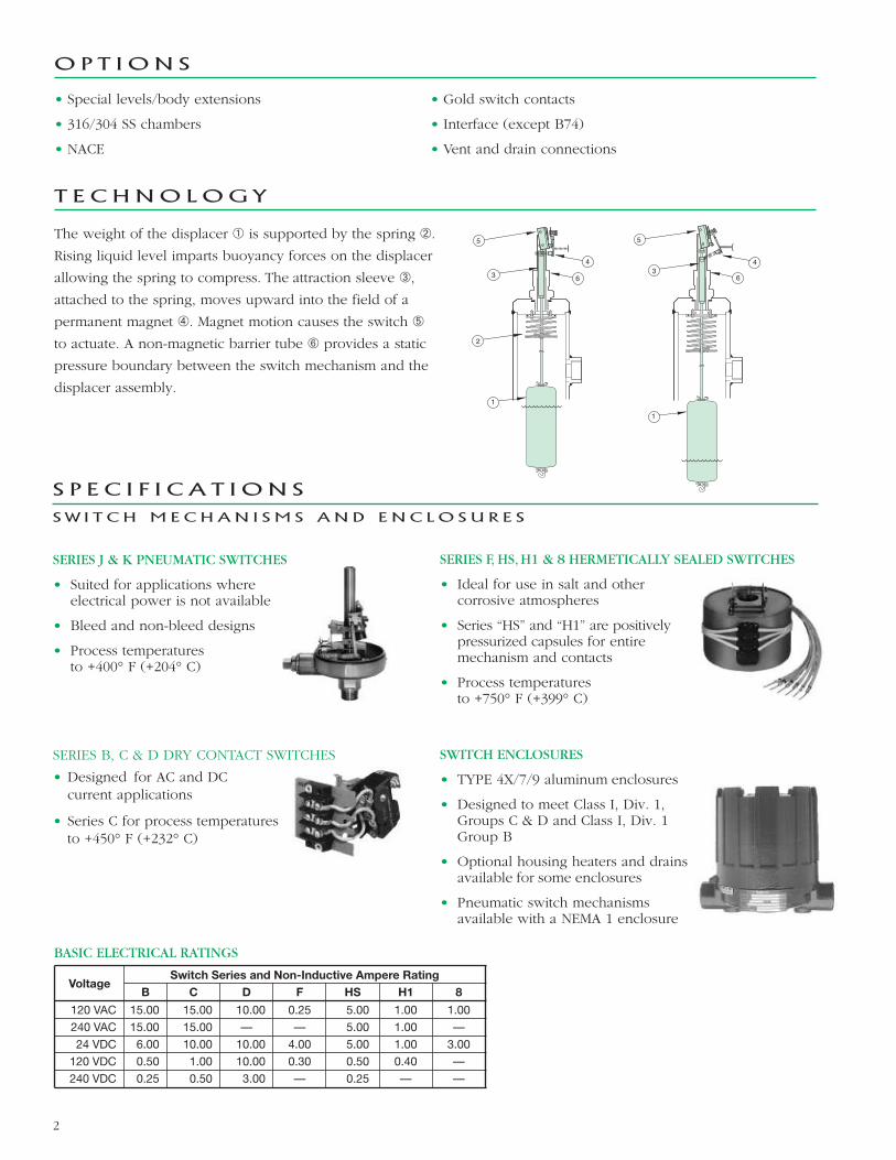
T E C HNO LOG Y
The weight of the displacer � is supported by the spring �.
Rising liquid level imparts buoyancy forces on the displacer
allowing the spring to compress. The attraction sleeve �,
attached to the spring, moves upward into the field of a
permanent magnet �. Magnet motion causes the switch �
to actuate. A non-magnetic barrier tube � provides a static
pressure boundary between the switch mechanism and the
displacer assembly.
1
63
5
1
634
5
2
4
SWITCH ENCLOSURES
• TYPE 4X/7/9 aluminum enclosures
• Designed to meet Class I, Div. 1,Groups C & D and Class I, Div. 1Group B
• Optional housing heaters and drainsavailable for some enclosures
• Pneumatic switch mechanismsavailable with a NEMA 1 enclosure
SERIES F, HS, H1 & 8 HERMETICALLY SEALED SWITCHES
• Ideal for use in salt and othercorrosive atmospheres
• Series “HS” and “H1” are positivelypressurized capsules for entiremechanism and contacts
• Process temperaturesto +750° F (+399° C)
SERIES J & K PNEUMATIC SWITCHES
• Suited for applications whereelectrical power is not available
• Bleed and non-bleed designs
• Process temperaturesto +400° F (+204° C)
S P E C I F I C A T I O N S
S W I T C H M E C H AN I S M S A N D E N C L O S U R E S
BASIC ELECTRICAL RATINGS
VoltageSwitch Series and Non-Inductive Ampere Rating
B C D F HS H1 8
120 VAC 15.00 15.00 10.00 0.25 5.00 1.00 1.00
240 VAC 15.00 15.00 — — 5.00 1.00 —
24 VDC 6.00 10.00 10.00 4.00 5.00 1.00 3.00
120 VDC 0.50 1.00 10.00 0.30 0.50 0.40 —
240 VDC 0.25 0.50 3.00 — 0.25 — —
SERIES B, C & D DRY CONTACT SWITCHES
• Designed for AC and DCcurrent applications
• Series C for process temperaturesto +450° F (+232° C)
3
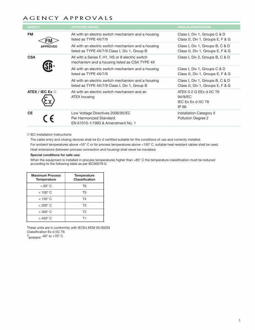
AGENCY APPROVED MODEL AREA CLASSIFICATION
FM All with an electric switch mechanism and a housing Class I, Div 1, Groups C & Dlisted as TYPE 4X/7/9 Class II, Div 1, Groups E, F & G
All with an electric switch mechanism and a housing Class I, Div 1, Groups B, C & Dlisted as TYPE 4X/7/9 Class I, Div 1, Group B Class II, Div 1, Groups E, F & G
CSA All with a Series F, H1, HS or 8 electric switch Class I, Div 2, Groups B, C & Dmechanism and a housing listed as CSA TYPE 4X
All with an electric switch mechanism and a housing Class I, Div 1, Groups C & Dlisted as TYPE 4X/7/9 Class II, Div 1, Groups E, F & G
All with an electric switch mechanism and a housing Class I, Div 1, Groups B, C & Dlisted as TYPE 4X/7/9 Class I, Div 1, Group B Class II, Div 1, Groups E, F & G
ATEX / IEC Ex � All with an electric switch mechanism and an ATEX II 2 G EEx d IIC T6ATEX housing 94/9/EC
IEC Ex Ex d IIC T6IP 66
CE Low Voltage Directives 2006/95/EC Installation Category IIPer Harmonized Standard: Pollution Degree 2EN 61010-1/1993 & Amendment No. 1
AG E N C Y A P P R O V A L S
� IEC Installation Instructions:
The cable entry and closing devices shall be Ex d certified suitable for the conditions of use and correctly installed.
For ambient temperatures above +55° C or for process temperatures above +150° C, suitable heat resistant cables shall be used.
Heat extensions (between process connection and housing) shall never be insulated.
Special conditions for safe use:
When the equipment is installed in process temperatures higher than +85° C the temperature classification must be reducedaccording to the following table as per IEC60079-0.
Maximum ProcessTemperature
TemperatureClassification
< 85° C T6
< 100° C T5
< 135° C T4
< 200° C T3
< 300° C T2
< 450° C T1
These units are in conformity with IECEx KEM 05.0020XClassification Ex d IIC T6Tambient -40° to +70° C
4
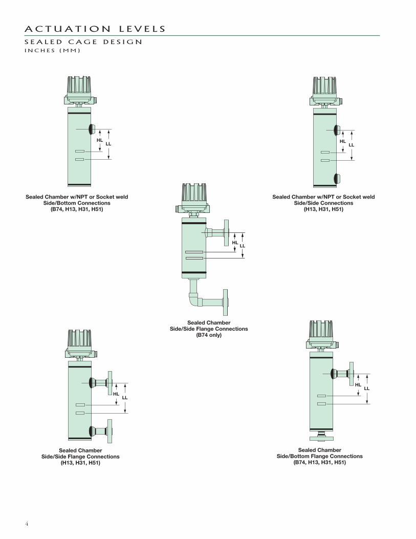
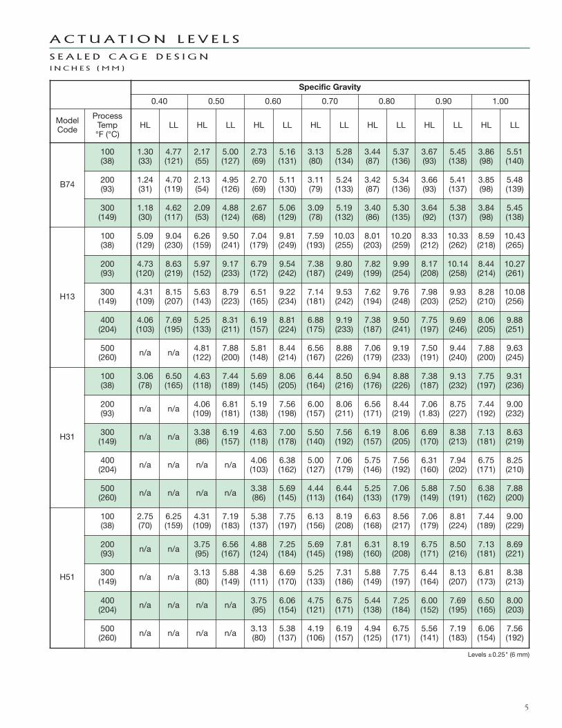
A C T U A T I O N L E V E L S
S E A L E D C AG E D E S I G NI N C H E S ( MM )
HLLL
HLLL
HLLL
HLLL
Sealed Chamber w/NPT or Socket weldSide/Bottom Connections
(B74, H13, H31, H51)
Sealed Chamber w/NPT or Socket weldSide/Side Connections
(H13, H31, H51)
Sealed ChamberSide/Bottom Flange Connections
(B74, H13, H31, H51)
Sealed ChamberSide/Side Flange Connections
(B74 only)
Sealed ChamberSide/Side Flange Connections
(H13, H31, H51)
HLLL
5
Specific Gravity
0.40 0.50 0.60 0.70 0.80 0.90 1.00
ModelCode
ProcessTemp°F (°C)
HL LL HL LL HL LL HL LL HL LL HL LL HL LL
B74
100(38)
1.30(33)
4.77(121)
2.17(55)
5.00(127)
2.73(69)
5.16(131)
3.13(80)
5.28(134)
3.44(87)
5.37(136)
3.67(93)
5.45(138)
3.86(98)
5.51(140)
200(93)
1.24(31)
4.70(119)
2.13(54)
4.95(126)
2.70(69)
5.11(130)
3.11(79)
5.24(133)
3.42(87)
5.34(136)
3.66(93)
5.41(137)
3.85(98)
5.48(139)
300(149)
1.18(30)
4.62(117)
2.09(53)
4.88(124)
2.67(68)
5.06(129)
3.09(78)
5.19(132)
3.40(86)
5.30(135)
3.64(92)
5.38(137)
3.84(98)
5.45(138)
H13
100(38)
5.09(129)
9.04(230)
6.26(159)
9.50(241)
7.04(179)
9.81(249)
7.59(193)
10.03(255)
8.01(203)
10.20(259)
8.33(212)
10.33(262)
8.59(218)
10.43(265)
200(93)
4.73(120)
8.63(219)
5.97(152)
9.17(233)
6.79(172)
9.54(242)
7.38(187)
9.80(249)
7.82(199)
9.99(254)
8.17(208)
10.14(258)
8.44(214)
10.27(261)
300(149)
4.31(109)
8.15(207)
5.63(143)
8.79(223)
6.51(165)
9.22(234)
7.14(181)
9.53(242)
7.62(194)
9.76(248)
7.98(203)
9.93(252)
8.28(210)
10.08(256)
400(204)
4.06(103)
7.69(195)
5.25(133)
8.31(211)
6.19(157)
8.81(224)
6.88(175)
9.19(233)
7.38(187)
9.50(241)
7.75(197)
9.69(246)
8.06(205)
9.88(251)
500(260) n/a n/a 4.81
(122)7.88(200)
5.81(148)
8.44(214)
6.56(167)
8.88(226)
7.06(179)
9.19(233)
7.50(191)
9.44(240)
7.88(200)
9.63(245)
H31
100(38)
3.06(78)
6.50(165)
4.63(118)
7.44(189)
5.69(145)
8.06(205)
6.44(164)
8.50(216)
6.94(176)
8.88(226)
7.38(187)
9.13(232)
7.75(197)
9.31(236)
200(93) n/a n/a 4.06
(109)6.81(181)
5.19(138)
7.56(198)
6.00(157)
8.06(211)
6.56(171)
8.44(219)
7.06(1.83)
8.75(227)
7.44(192)
9.00(232)
300(149) n/a n/a 3.38
(86)6.19(157)
4.63(118)
7.00(178)
5.50(140)
7.56(192)
6.19(157)
8.06(205)
6.69(170)
8.38(213)
7.13(181)
8.63(219)
400(204) n/a n/a n/a n/a 4.06
(103)6.38(162)
5.00(127)
7.06(179)
5.75(146)
7.56(192)
6.31(160)
7.94(202)
6.75(171)
8.25(210)
500(260) n/a n/a n/a n/a 3.38
(86)5.69(145)
4.44(113)
6.44(164)
5.25(133)
7.06(179)
5.88(149)
7.50(191)
6.38(162)
7.88(200)
H51
100(38)
2.75(70)
6.25(159)
4.31(109)
7.19(183)
5.38(137)
7.75(197)
6.13(156)
8.19(208)
6.63(168)
8.56(217)
7.06(179)
8.81(224)
7.44(189)
9.00(229)
200(93) n/a n/a 3.75
(95)6.56(167)
4.88(124)
7.25(184)
5.69(145)
7.81(198)
6.31(160)
8.19(208)
6.75(171)
8.50(216)
7.13(181)
8.69(221)
300(149) n/a n/a 3.13
(80)5.88(149)
4.38(111)
6.69(170)
5.25(133)
7.31(186)
5.88(149)
7.75(197)
6.44(164)
8.13(207)
6.81(173)
8.38(213)
400(204) n/a n/a n/a n/a 3.75
(95)6.06(154)
4.75(121)
6.75(171)
5.44(138)
7.25(184)
6.00(152)
7.69(195)
6.50(165)
8.00(203)
500(260) n/a n/a n/a n/a 3.13
(80)5.38(137)
4.19(106)
6.19(157)
4.94(125)
6.75(171)
5.56(141)
7.19(183)
6.06(154)
7.56(192)
A C T U A T I O N L E V E L S
S E A L E D C AG E D E S I G NI N C H E S ( MM )
Levels ±0.25" (6 mm)

D I M E N S I O N A L S P E C I F I C A T I O N S
S E A L E D C AG E D E S I G NI N C H E S ( MM )
6
HL
B
LL
Bottomconnection
E
C
A
PluggedE
7.94*(201)
FG
E
C
PluggedE
7.94*(201)
HLLL
B
FG
A
1" NPTdrain
E
C
PluggedE
7.94*(201)
HL
B
LL
D
FG
A
1" NPTdrain
E
C
PluggedE
7.94*(201)
HL
B
LL
D
FG
A
Sealed Chamber w/NPT or Socket weldSide/Bottom Connections
(B74, H13, H31, H51)
Sealed Chamber w/NPT or Socket weldSide/Side Connections
(H13, H31, H51)
Sealed ChamberSide/Bottom Flange Connections
(B74, H13, H31, H51)
Sealed ChamberSide/Side Flange Connections
(B74 only)
Sealed ChamberSide/Side Flange Connections
(H13, H31, H51)
FRotationclearance
HLLL
EE
plugged
G
7.94(201)
C
A
B
* These dimensions increase by 2.19 (56) when usedwith Series HS switches with terminal blocks.
Housing F G
NEMA 1 4.69 (119) 5.00 (127)
TYPE 4X/7/9*5.93 (151) 3.78 (96)
TYPE 4X/7/9 Group B*
Conduit Connections E
Electric Switches:Type 4X/7/9: 1" NPTGroup B: 1" NPT
Pneumatic Switches:NEMA 1: 1⁄4" NPT
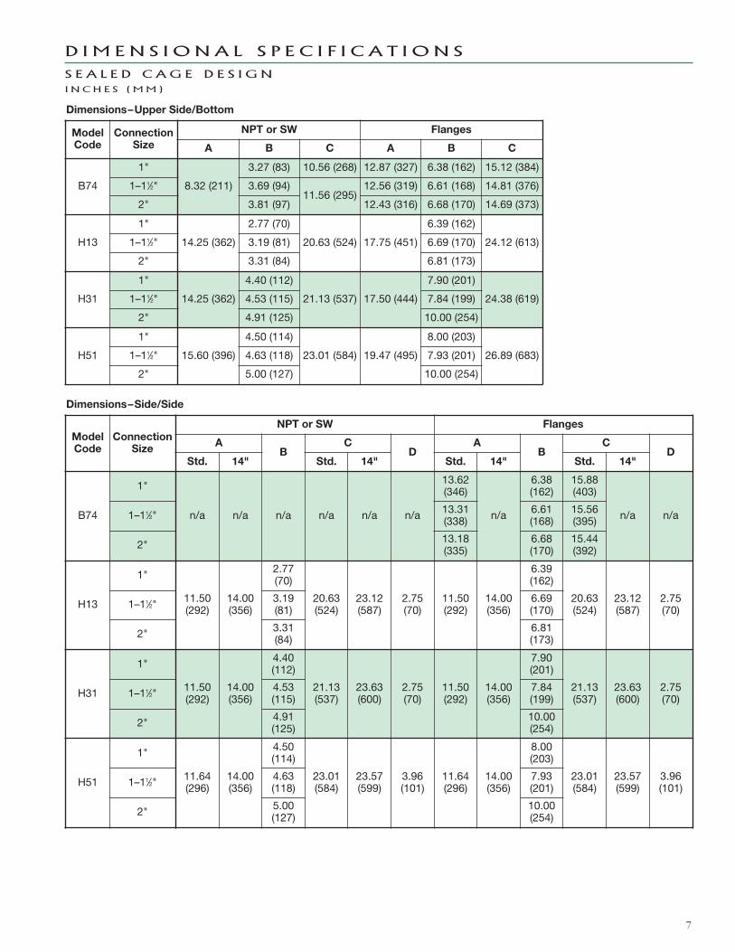
Dimensions–Side/Side
7
ModelCode
ConnectionSize
NPT or SW Flanges
A B C A B C
B74
1"
8.32 (211)
3.27 (83) 10.56 (268) 12.87 (327) 6.38 (162) 15.12 (384)
1–11⁄2" 3.69 (94)11.56 (295)
12.56 (319) 6.61 (168) 14.81 (376)
2" 3.81 (97) 12.43 (316) 6.68 (170) 14.69 (373)
H13
1"
14.25 (362)
2.77 (70)
20.63 (524) 17.75 (451)
6.39 (162)
24.12 (613)1–11⁄2" 3.19 (81) 6.69 (170)
2" 3.31 (84) 6.81 (173)
H31
1"
14.25 (362)
4.40 (112)
21.13 (537) 17.50 (444)
7.90 (201)
24.38 (619)1–11⁄2" 4.53 (115) 7.84 (199)
2" 4.91 (125) 10.00 (254)
H51
1"
15.60 (396)
4.50 (114)
23.01 (584) 19.47 (495)
8.00 (203)
26.89 (683)1–11⁄2" 4.63 (118) 7.93 (201)
2" 5.00 (127) 10.00 (254)
ModelCode
ConnectionSize
NPT or SW Flanges
AB
CD
AB
CD
Std. 14" Std. 14" Std. 14" Std. 14"
B74
1"
n/a n/a n/a n/a n/a n/a
13.62(346)
n/a
6.38(162)
15.88(403)
n/a n/a1–11⁄2" 13.31(338)
6.61(168)
15.56(395)
2" 13.18(335)
6.68(170)
15.44(392)
H13
1"
11.50(292)
14.00(356)
2.77(70)
20.63(524)
23.12(587)
2.75(70)
11.50(292)
14.00(356)
6.39(162)
20.63(524)
23.12(587)
2.75(70)1–11⁄2" 3.19
(81)6.69(170)
2" 3.31(84)
6.81(173)
H31
1"
11.50(292)
14.00(356)
4.40(112)
21.13(537)
23.63(600)
2.75(70)
11.50(292)
14.00(356)
7.90(201)
21.13(537)
23.63(600)
2.75(70)1–11⁄2" 4.53
(115)7.84(199)
2" 4.91(125)
10.00(254)
H51
1"
11.64(296)
14.00(356)
4.50(114)
23.01(584)
23.57(599)
3.96(101)
11.64(296)
14.00(356)
8.00(203)
23.01(584)
23.57(599)
3.96(101)1–11⁄2" 4.63
(118)7.93(201)
2" 5.00(127)
10.00(254)
D I M E N S I O N A L S P E C I F I C A T I O N S
S E A L E D C AG E D E S I G NI N C H E S ( MM )
Dimensions–Upper Side/Bottom

HLLL
HLLL
HLLL
HLLL
Flanged Top Chamber w/NPT orSocket weld Side/Bottom Connections
(C74, H15, H32, H52)
Flanged Top Chamber w/NPT orSocket weld Side/Side Connections
(H15, H32, H52)
Flanged Top ChamberSide/Bottom Flange Connections
(C74, H15, H32, H52)
Flanged Top ChamberSide/Side Flange Connections
(H15, H32, H52)
Flanged Top ChamberSide/Side Flange Connections
(C74 only)
8
HL
LL
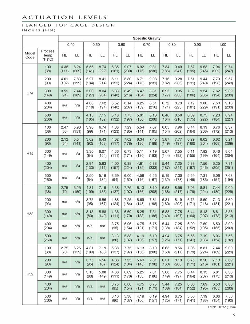
A C T U A T I O N L E V E L S
F L A NG E D TO P C AG E D E S I G NI N C H E S ( MM )
9
Specific Gravity
0.40 0.50 0.60 0.70 0.80 0.90 1.00
ModelCode
ProcessTemp°F (°C)
HL LL HL LL HL LL HL LL HL LL HL LL HL LL
C74
100(38)
4.38(111)
8.24(209)
5.56(141)
8.74(222)
6.35(161)
9.07(230)
6.92(176)
9.31(236)
7.34(186)
9.49(241)
7.67(195)
9.63(245)
7.94(202)
9.74(247)
200(93)
4.01(102)
7.83(199)
5.27(134)
8.41(214)
6.11(155)
8.80(224)
6.71(170)
9.08(231)
7.16(182)
9.28(236)
7.51(191)
9.44(240)
7.79(198)
9.57(243)
300(149)
3.59(91)
7.44(189)
5.00(127)
8.04(204)
5.83(148)
8.49(216)
6.47(164)
8.81(224)
6.95(177)
9.05(230)
7.32(186)
9.24(235)
7.62(194)
9.39(239)
400(204) n/a n/a 4.63
(118)7.62(194)
5.52(140)
8.14(207)
6.25(159)
8.51(216)
6.72(171)
8.79(223)
7.12(181)
9.00(229)
7.50(191)
9.18(233)
500(260) n/a n/a 4.15
(105)7.15(182)
5.18(132)
7.75(197)
5.91(150)
8.18(208)
6.46(164)
8.50(216)
6.89(175)
8.75(222)
7.23(184)
8.94(227)
H15
100(38)
2.47(63)
5.93(151)
3.90(99)
6.74(171)
4.86(123)
7.29(185)
5.54(141)
7.67(195)
6.05(154)
7.96(202)
6.44(164)
8.19(208)
6.76(172)
8.37(213)
200(93)
2.12(54)
5.54(141)
3.62(92)
6.43(163)
4.62(117)
7.02(178)
8.34(136)
7.45(189)
5.87(149)
7.77(197)
6.29(160)
8.02(204)
6.62(168)
8.21(209)
300(149) n/a n/a 3.30
(84)6.07(154)
4.36(111)
6.73(171)
5.11(130)
7.19(183)
5.67(144)
7.55(192)
6.11(155)
7.82(199)
6.46(164)
8.04(204)
400(204) n/a n/a 2.94
(133)5.63(211)
4.00(157)
6.38(224)
4.81(175)
6.88(233)
5.44(187)
7.25(241)
5.88(197)
7.56(246)
6.25(205)
7.81(251)
500(260) n/a n/a 2.50
(64)5.19(132)
3.69(94)
6.00(152)
4.56(116)
6.56(167)
5.19(132)
7.00(178)
5.69(145)
7.31(186)
6.06(154)
7.63(194)
H32
100(38)
2.75(70)
6.25(159)
4.31(109)
7.19(183)
5.38(137)
7.75(197)
6.13(156)
8.19(208)
6.63(168)
8.56(217)
7.06(179)
8.81(224)
7.44(189)
9.00(229)
200(93) n/a n/a 3.75
(95)6.56(167)
4.88(124)
7.25(184)
5.69(145)
7.81(198)
6.31(160)
8.19(208)
6.75(171)
8.50(216)
7.13(181)
8.69(221)
300(149) n/a n/a 3.13
(80)5.88(149)
4.38(111)
6.69(170)
5.25(133)
7.31(186)
5.88(149)
7.75(197)
6.44(164)
8.13(207)
6.81(173)
8.38(213)
400(204) n/a n/a n/a n/a 3.75
(95)6.06(154)
4.75(121)
6.75(171)
5.44(138)
7.25(184)
6.00(152)
7.69(195)
6.50(165)
8.00(203)
500(260) n/a n/a n/a n/a 3.13
(80)5.38(137)
4.19(106)
6.19(157)
4.94(125)
6.75(171)
5.56(141)
7.19(183)
6.06(154)
7.56(192)
H52
100(38)
2.75(70)
6.25(159)
4.31(109)
7.19(183)
5.38(137)
7.75(197)
6.13(156)
8.19(208)
6.63(168)
8.56(217)
7.06(179)
8.81(224)
7.44(189)
9.00(229)
200(93) n/a n/a 3.75
(95)6.56(167)
4.88(124)
7.25(184)
5.69(145)
7.81(198)
6.31(160)
8.19(208)
6.75(171)
8.50(216)
7.13(181)
8.69(221)
300(149) n/a n/a 3.13
(80)5.88(149)
4.38(111)
6.69(170)
5.25(133)
7.31(186)
5.88(149)
7.75(197)
6.44(164)
8.13(207)
6.81(173)
8.38(213)
400(204) n/a n/a n/a n/a 3.75
(95)6.06(154)
4.75(121)
6.75(171)
5.44(138)
7.25(184)
6.00(152)
7.69(195)
6.50(165)
8.00(203)
500(260) n/a n/a n/a n/a 3.13
(80)5.38(137)
4.19(106)
6.19(157)
4.94(125)
6.75(171)
5.56(141)
7.19(183)
6.06(154)
7.56(192)
A C T U A T I O N L E V E L S
F L A NG E D TO P C AG E D E S I G NI N C H E S ( MM )
Levels ±0.25" (6 mm)
10
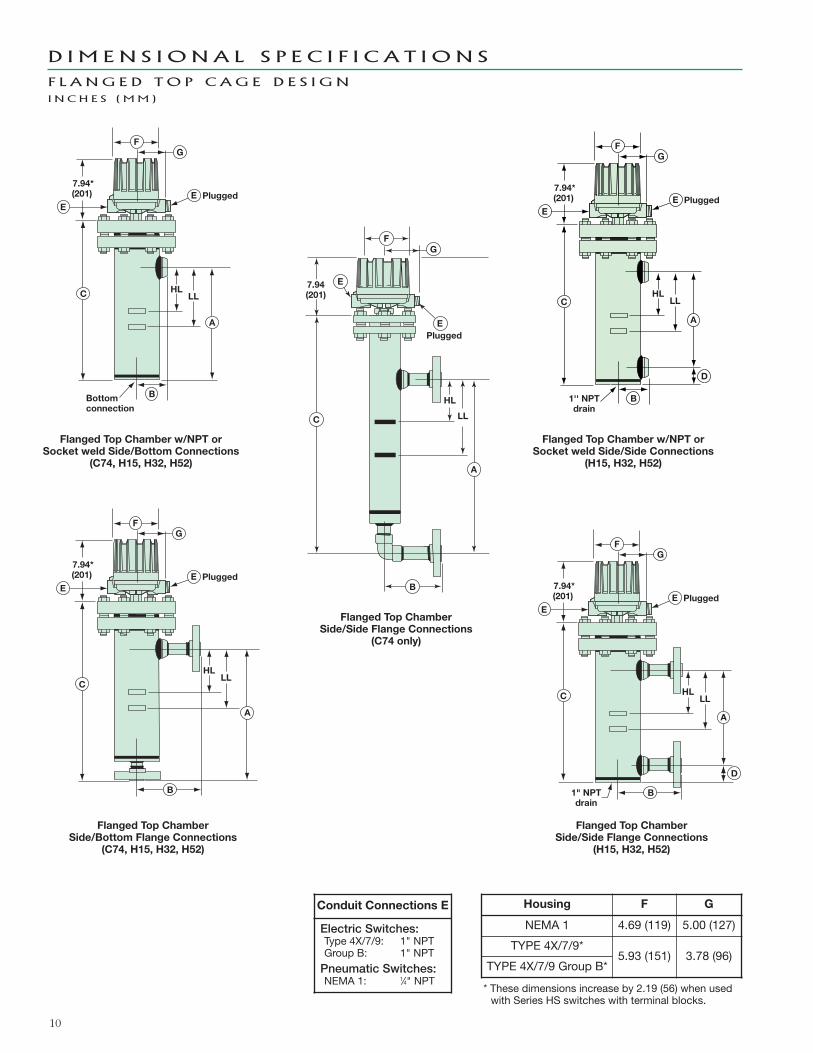
D I M E N S I O N A L S P E C I F I C A T I O N S
F L A NG E D TO P C AG E D E S I G NI N C H E S ( MM )
HL
B
LL
E
C
PluggedE
7.94*(201)
Bottomconnection
FG
A
HLLL
E
C
PluggedE
7.94*(201)
FG
A
B
HL
B
LL
E
C
PluggedE
7.94*(201)
1'' NPTdrain
D
FG
A
HLLL
1" NPTdrain
E
C
PluggedE
7.94*(201)
D
FG
A
B
Flanged Top Chamber w/NPT orSocket weld Side/Bottom Connections
(C74, H15, H32, H52)
Flanged Top Chamber w/NPT orSocket weld Side/Side Connections
(H15, H32, H52)
Flanged Top ChamberSide/Bottom Flange Connections
(C74, H15, H32, H52)
Flanged Top ChamberSide/Side Flange Connections
(H15, H32, H52)
Flanged Top ChamberSide/Side Flange Connections
(C74 only)
HL
LL
Plugged
7.94(201)
C
E
B
E
G
A
F
* These dimensions increase by 2.19 (56) when usedwith Series HS switches with terminal blocks.
Housing F G
NEMA 1 4.69 (119) 5.00 (127)
TYPE 4X/7/9*5.93 (151) 3.78 (96)
TYPE 4X/7/9 Group B*
Conduit Connections E
Electric Switches:Type 4X/7/9: 1" NPTGroup B: 1" NPT
Pneumatic Switches:NEMA 1: 1⁄4" NPT
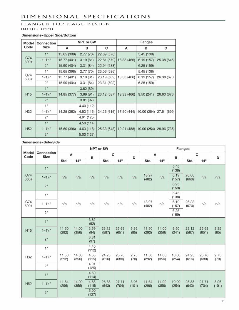
ModelCode
ConnectionSize
NPT or SW Flanges
AB
CD
AB
CD
Std. 14" Std. 14" Std. 14" Std. 14"
C74300#
1"
n/a n/a n/a n/a n/a n/a 18.97(482) n/a
5.45(138)
26.00(660) n/a n/a1–11⁄2" 6.19
(157)
2" 6.25(159)
C74600#
1"
n/a n/a n/a n/a n/a n/a 18.97(482) n/a
5.45(138)
26.38(670) n/a n/a1–11⁄2" 6.19
(157)
2" 6.25(159)
H15
1"
11.50(292)
14.00(356)
3.62(92)
23.12(587)
25.63(651)
3.35(85)
11.50(292)
14.00(356)
9.50(241)
23.12(587)
25.63(651)
3.35(85)1–11⁄2" 3.69
(94)
2" 3.81(97)
H32
1"
11.50(292)
14.00(356)
4.40(112)
24.25(616)
26.76(680)
2.75(70)
11.50(292)
14.00(356)
10.00(254)
24.25(616)
26.76(680)
2.75(70)1–11⁄2" 4.53
(115)
2" 4.91(125)
H52
1"
11.64(296)
14.00(356)
4.50(114)
25.33(643)
27.71(704)
3.96(101)
11.64(296)
14.00(356)
10.00(254)
25.33(643)
27.71(704)
3.96(101)1–11⁄2" 4.63
(115)
2" 5.00(127)
11
ModelCode
ConnectionSize
NPT or SW Flanges
A B C A B C
C74300#
1" 15.65 (398) 2.77 (70) 22.69 (576)
18.33 (466)
5.45 (138)
25.38 (645)1–11⁄2" 15.77 (401) 3.19 (81) 22.81 (579) 6.19 (157)
2" 15.90 (404) 3.31 (84) 22.94 (583) 6.25 (159)
C74600#
1" 15.65 (398) 2.77 (70) 23.06 (586)
18.33 (466)
5.45 (138)
26.38 (670)1–11⁄2" 15.77 (401) 3.19 (81) 23.19 (589) 6.19 (157)
2" 15.90 (404) 3.31 (84) 23.31 (592) 6.25 (159)
H15
1"
14.85 (377)
3.62 (89)
23.12 (587) 18.33 (466) 9.50 (241) 26.63 (676)1–11⁄2" 3.69 (91)
2" 3.81 (97)
H32
1"
14.25 (362)
4.40 (112)
24.25 (616) 17.50 (444) 10.00 (254) 27.51 (699)1–11⁄2" 4.53 (115)
2" 4.91 (125)
H52
1"
15.60 (396)
4.50 (114)
25.33 (643) 19.21 (488) 10.00 (254) 28.96 (736)1–11⁄2" 4.63 (118)
2" 5.00 (127)
Dimensions–Side/Side
D I M E N S I O N A L S P E C I F I C A T I O N S
F L A NG E D TO P C AG E D E S I G NI N C H E S ( MM )
Dimensions–Upper Side/Bottom
12
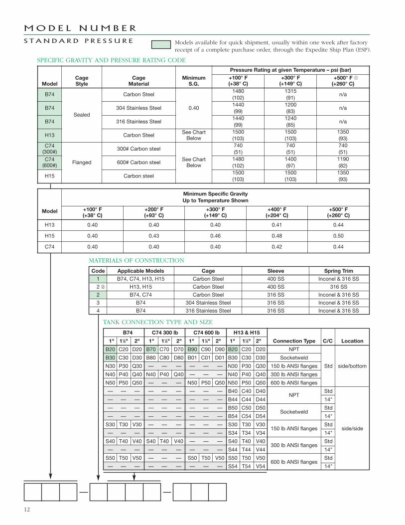
SPECIFIC GRAVITY AND PRESSURE RATING CODE
MATERIALS OF CONSTRUCTION
MOD E L N UM B E R
S T A N D A R D P R E S S U R E
Code Applicable Models Cage Sleeve Spring Trim
1 B74, C74, H13, H15 Carbon Steel 400 SS Inconel & 316 SS
2 � H13, H15 Carbon Steel 400 SS 316 SS
2 B74, C74 Carbon Steel 316 SS Inconel & 316 SS
3 B74 304 Stainless Steel 316 SS Inconel & 316 SS
4 B74 316 Stainless Steel 316 SS Inconel & 316 SS
TANK CONNECTION TYPE AND SIZE
B74 C74 300 lb C74 600 lb H13 & H15
1" 11⁄2" 2" 1" 11⁄2" 2" 1" 11⁄2" 2" 1" 11⁄2" 2" Connection Type C/C Location
B20 C20 D20 B70 C70 D70 B90 C90 D90 B20 C20 D20 NPT
B30 C30 D30 B80 C80 D80 B01 C01 D01 B30 C30 D30 Socketweld
N30 P30 Q30 — — — — — — N30 P30 Q30 150 lb ANSI flanges Std side/bottom
N40 P40 Q40 N40 P40 Q40 — — — N40 P40 Q40 300 lb ANSI flanges
N50 P50 Q50 — — — N50 P50 Q50 N50 P50 Q50 600 lb ANSI flanges
— — — — — — — — — B40 C40 D40NPT
Std
— — — — — — — — — B44 C44 D44 14"
— — — — — — — — — B50 C50 D50Socketweld
Std
— — — — — — — — — B54 C54 D54 14"
S30 T30 V30 — — — — — — S30 T30 V30150 lb ANSI flanges
Stdside/side
— — — — — — — — — S34 T34 V34 14"
S40 T40 V40 S40 T40 V40 — — — S40 T40 V40300 lb ANSI flanges
Std
— — — — — — — — — S44 T44 V44 14"
S50 T50 V50 — — — S50 T50 V50 S50 T50 V50600 lb ANSI flanges
Std
— — — — — — — — — S54 T54 V54 14"
ModelCageStyle
CageMaterial
MinimumS.G.
Pressure Rating at given Temperature – psi (bar)+100° F(+38° C)
+300° F(+149° C)
+500° F �(+260° C)
B74
Sealed
Carbon Steel
0.40
1480(102)
1315(91)
n/a
B74 304 Stainless Steel1440(99)
1200(83)
n/a
B74 316 Stainless Steel1440(99)
1240(85)
n/a
H13 Carbon Steel See ChartBelow
1500(103)
1500(103)
1350(93)
C74(300#)
Flanged
300# Carbon steel
See ChartBelow
740(51)
740(51)
740(51)
C74(600#) 600# Carbon steel
1480(102)
1400(97)
1190(82)
H15 Carbon steel1500(103)
1500(103)
1350(93)
Model
Minimum Specific GravityUp to Temperature Shown
+100° F(+38° C)
+200° F(+93° C)
+300° F(+149° C)
+400° F(+204° C)
+500° F(+260° C)
H13 0.40 0.40 0.40 0.41 0.44
H15 0.40 0.43 0.46 0.48 0.50
C74 0.40 0.40 0.40 0.42 0.44
Models available for quick shipment, usually within one week after factoryreceipt of a complete purchase order, through the Expedite Ship Plan (ESP).
13
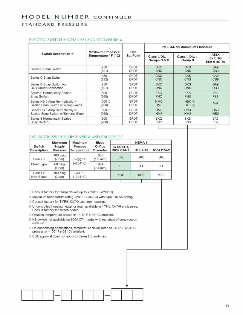
ELECTRIC SWITCH MECHANISM AND ENCLOSURE �
Maximum Maximum Bleed NEMA 1Switch Supply Process Orifice B74,C74-1,
Description Pressure Temperature Diameter 300# C74-2 H13, H15 600# C74-2
100 psig .063JDE JKE JKESeries J (7 bar) +400° F (1.6 mm)
Bleed Type 60 psig (+204° C) .094JEE JLE JLE(4 bar) (2.4 mm)
Series k 100 psig +400° F— KOE KOE KPENon-Bleed (7 bar) (+204° C)
PNEUMATIC SWITCH MECHANISM AND ENCLOSURE
� Consult factory for temperatures up to +750° F (+399° C).
� Maximum temperature rating +200° F (+93° C) with type 316 SS spring.
� Consult factory for TYPE 4X/7/9 cast iron housings.� Uncontrolled housing heater or drain available in TYPE 4X/7/9 enclosures.Consult factory for switch codes.
� Process temperature based on +100° F (+38° C) ambient.
� HS switch not available on 600# C74 model with materials of constructioncode –2.
On condensing applications, temperature down-rated to +400° F (204° C)process at +100° F (+38° C) ambient.
CSA approval does not apply to Series HE switches.
MOD E L N UM B E R CON T I N U E D
S T A N D A R D P R E S S U R E
Switch Description �Maximum Process �Temperature ° F (° C)
OneSet Point
TYPE 4X/7/9 Aluminum Enclosure
Class I, Div. 1,Groups C & D
Class I, Div. 1,Group B
ATEXEx II 2G
EEx d IIC T6
Series B Snap Switch 250(121)
SPDTDPDT
BKQBNQ
BKSBNS
BA9BB9
Series C Snap Switch 450(232)
SPDTDPDT
CKQCNQ
CKSCNS
CA9CB9
Series D Snap Switch forDC Current Application
250(121)
SPDTDPDT
DKQDNQ
DKSDNS
DA9DB9
Series F Hermetically SealedSnap Switch
500(260)
SPDTDPDT
FKQFNQ
FKSFNS
FA9FB9
Series HS 5 Amp Hermetically �Sealed Snap Switch w/Wiring Leads
500(260)
SPDTDPDT
HMCHMF
HEKHET N/A
Series HS 5 Amp Hermetically �Sealed Snap Switch w/Terminal Block
500(260)
SPDTDPDT
HM3HM7
HM4HM8
HA9HB9
Series 8 Hermetically SealedSnap Switch
500(260)
SPDTDPDT
8KQ8NQ
8KS8NS
8A98B9
14
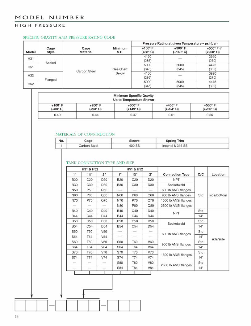
MOD E L N UM B E R
H I G H P R E S S U R E
MATERIALS OF CONSTRUCTION
No. Cage Sleeve Spring Trim
1 Carbon Steel 400 SS Inconel & 316 SS
H31 & H32 H51 & H52
1" 11⁄2" 2" 1" 11⁄2" 2" Connection Type C/C Location
B20 C20 D20 B20 C20 D20 NPT
B30 C30 D30 B30 C30 D30 Socketweld
N50 P50 Q50 — — — 600 lb ANSI flanges
N60 P60 Q60 N60 P60 Q60 900 lb ANSI flanges Std side/bottom
N70 P70 Q70 N70 P70 Q70 1500 lb ANSI flanges
— — — N80 P80 Q80 2500 lb ANSI flanges
B40 C40 D40 B40 C40 D40NPT
Std
B44 C44 D44 B44 C44 D44 14"
B50 C50 D50 B50 C50 D50Socketweld
Std
B54 C54 D54 B54 C54 D54 14"
S50 T50 V50 — — —600 lb ANSI flanges
Std
S54 T54 V54 — — — 14"side/side
S60 T60 V60 S60 T60 V60900 lb ANSI flanges
Std
S64 T64 V64 S64 T64 V64 14"
S70 T70 V70 S70 T70 V701500 lb ANSI flanges
Std
S74 T74 V74 S74 T74 V74 14"
— — — S80 T80 V802500 lb ANSI flanges
Std
— — — S84 T84 V84 14"
TANK CONNECTION TYPE AND SIZE
SPECIFIC GRAVITY AND PRESSURE RATING CODE
ModelCageStyle
CageMaterial
MinimumS.G.
Pressure Rating at given Temperature – psi (bar)+100° F(+38° C)
+300° F(+149° C)
+500° F �(+260° C)
H31Sealed
Carbon SteelSee ChartBelow
4150(286)
—3920(270)
H515000(345)
5000(345)
4475(309)
H32Flanged
4150(286)
—3920(270)
H525000(345)
5000(345)
4475(309)
Minimum Specific GravityUp to Temperature Shown
+100° F(+38° C)
+200° F(+93° C)
+300° F(+149° C)
+400° F(+204° C)
+500° F(+260° C)
0.40 0.44 0.47 0.51 0.56
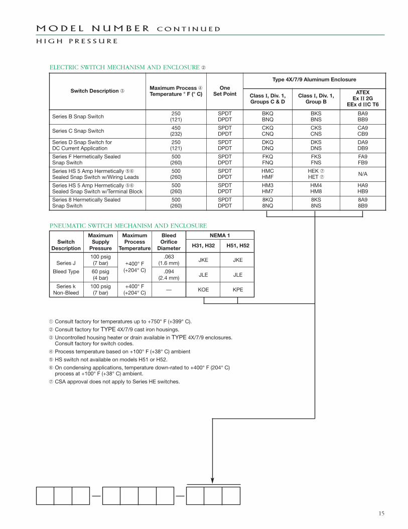
ELECTRIC SWITCH MECHANISM AND ENCLOSURE �
15
Maximum Maximum Bleed NEMA 1Switch Supply Process Orifice
Description Pressure Temperature Diameter H31, H32 H51, H52
100 psig .063JKE JKESeries J (7 bar) +400° F (1.6 mm)
Bleed Type 60 psig (+204° C) .094JLE JLE(4 bar) (2.4 mm)
Series k 100 psig +400° F— KOE KPENon-Bleed (7 bar) (+204° C)
PNEUMATIC SWITCH MECHANISM AND ENCLOSURE
� Consult factory for temperatures up to +750° F (+399° C).
� Consult factory for TYPE 4X/7/9 cast iron housings.� Uncontrolled housing heater or drain available in TYPE 4X/7/9 enclosures.Consult factory for switch codes.
� Process temperature based on +100° F (+38° C) ambient
� HS switch not available on models H51 or H52.
� On condensing applications, temperature down-rated to +400° F (204° C)process at +100° F (+38° C) ambient.
CSA approval does not apply to Series HE switches.
MOD E L N UM B E R CON T I N U E D
H I G H P R E S S U R E
Switch Description �Maximum Process �Temperature ° F (° C)
OneSet Point
Type 4X/7/9 Aluminum Enclosure
Class I, Div. 1,Groups C & D
Class I, Div. 1,Group B
ATEXEx II 2G
EEx d IIC T6
Series B Snap Switch 250(121)
SPDTDPDT
BKQBNQ
BKSBNS
BA9BB9
Series C Snap Switch 450(232)
SPDTDPDT
CKQCNQ
CKSCNS
CA9CB9
Series D Snap Switch forDC Current Application
250(121)
SPDTDPDT
DKQDNQ
DKSDNS
DA9DB9
Series F Hermetically SealedSnap Switch
500(260)
SPDTDPDT
FKQFNQ
FKSFNS
FA9FB9
Series HS 5 Amp Hermetically ��Sealed Snap Switch w/Wiring Leads
500(260)
SPDTDPDT
HMCHMF
HEK HET
N/A
Series HS 5 Amp Hermetically ��Sealed Snap Switch w/Terminal Block
500(260)
SPDTDPDT
HM3HM7
HM4HM8
HA9HB9
Series 8 Hermetically SealedSnap Switch
500(260)
SPDTDPDT
8KQ8NQ
8KS8NS
8A98B9
The quality assurance system in place at
MAGNETROL guarantees the highest level
of quality throughout the company.
MAGNETROL is committed to providing
full customer satisfaction both in quality
products and quality service.
The MAGNETROL quality assurance system
is registered to ISO 9001 affirming its com-
mitment to known international quality
standards providing the strongest assurance
of product/service quality available.
Several External Cage Switches are available
for quick shipment, usually within one week
after factory receipt of a complete purchase
order, through the Expedite Ship Plan (ESP).
To take advantage of ESP, match the color
coded model number codes in the selection
charts (standard dimensions apply).
ESP service may not apply to orders of ten units
or more. Contact your local representative for
lead times on larger volume orders, as well as
other products and options.
EExpedite
SShipPPlan
All MAGNETROL mechanical level and flow
controls are warranted free of defects in
materials or workmanship for five full years
from the date of original factory shipment.
If returned within the warranty period; and,
upon factory inspection of the control, the
cause of the claim is determined to be covered
under the warranty; then, MAGNETROL will
repair or replace the control at no cost to the
purchaser (or owner) other than transportation.
MAGNETROL shall not be liable for misappli-
cation, labor claims, direct or consequential
damage or expense arising from the installa-
tion or use of equipment. There are no
other warranties expressed or implied, except
special written warranties covering some
MAGNETROL products.
BULLETIN: 46-121.23EFFECTIVE: March 2012SUPERSEDES: August 2010
5300 Belmont Road • Downers Grove, Illinois 60515-4499 • 630-969-4000 • Fax 630-969-9489 • www.magnetrol.com145 Jardin Drive, Units 1 & 2 • Concord, Ontario Canada L4K 1X7 • 905-738-9600 • Fax 905-738-1306Heikensstraat 6 • B 9240 Zele, Belgium • 052 45.11.11 • Fax 052 45.09.93Regent Business Ctr., Jubilee Rd. • Burgess Hill, Sussex RH15 9TL U.K. • 01444-871313 • Fax 01444-871317
Copyright © 2012 Magnetrol International, Incorporated. All rights reserved. Printed in the USA.Performance specifications are effective with date of issue and are subject to change without notice.
QUA L I T Y
E S P
W A R R A N T Y
Magnetrol & Magnetrol logotype are registered trademarks of Magnetrol International, Incorporated.