!2-).' 0#4 - sporty's · g1000 trainer bezel the g1000 trainer bezel surrounds the...
TRANSCRIPT


Interface OverviewThe G1000 Trainer interface is composed of a menu bar, the G1000 Control Display Unit(CDU) bezel and the G1000 Control Display.

Menu BarThe menu bar is located across the top of the G1000 Trainer interface window andconsists of the following menus (corresponding menu options are listed inparentheses):
File (Power-up; Exit)
Options (Screen Capture; Reversionary Mode; PFD Mode; MFD Mode;Simulate Failures, Pause, Joystick Axis Configuration, WFDE PredictionProgram, Enable Sound)
The ‘Screen Capture’ menu option allows the user to capture screenshotsof the G1000 Trainer interface. These screenshots are generated inbitmap format (".bmp" file extension) and are automatically saved in thesame file folder as the one in which the G1000 Trainer softwareapplication was installed.
Airframe (displays a list of selectable airframes)
Help (G1000 Trainer Help; About)

G1000 Trainer BezelThe G1000 Trainer bezel surrounds the control display and consists of the same knobs, keysand softkeys as those found on the G1000 system.

G1000 Control DisplayThe G1000 control display is surrounded by the control bezel and can be configured as either a Primary FlightDisplay (PFD) or as a Multi Function Display (MFD).
The G1000 trainer also supports a dual screen mode, allowing the PFD and MFD to be used simultaneously.

Opening and Powering Up the G1000 TrainerTo open the G1000 Trainer:
1a. Double-click the G1000 Trainer shortcut located on the PC desktop (the‘Shortcut on Desktop’ option is selected by default at installation).
or1b. Click the G1000 Trainer shortcut located in the PC Start menu under ‘Programs’
(the ‘Shortcut in Start Menu’ option is selected by default at installation).
To power up the G1000 Trainer:
1a. Click the power button located at the top left corner of the G1000 Trainer bezel.
or1b. Click the ‘File’ menu and select ‘Power-up’.
Upon power-up, the system typically takes several seconds to initialize.
Only when the G1000 system is powered up in MFD mode is the Power-upPage displayed. The Power-up Page provides checklist information aswell as land, terrain and aviation database information.

To exit the Power-up Page and display the MAP Page, press the ENT keyor press the first softkey from the right (or press ‘F12’).

Starting the G1000 Trainer in Dual Screen ModeTo display the G1000 Trainer in Dual Screen mode:
1. On the Start Menu, select ‘Programs’, ‘G1000 Trainer’, and then ‘Start DualScreen Trainer’. Both the G1000 Trainer PFD and the G1000 Trainer MFDdisplay.
2. On the Start Menu, select ‘Programs’, ‘G1000 Trainer’, and then ‘StartRemotes’. This launches the remotes for the PFD and the MFD.
3. Click the power buttons located at the top left corners of the G1000 Trainerbezels.
The AFCS Controls work with the PFD. The Garmin Control Unit workswith the MFD.

Pausing the G1000 TrainerPausing the Trainer causes the airspeed, altitude, vertical speed and position of theaircraft to be paused.
To pause the G1000 Trainer:
Click the ‘Options’ menu and select ‘Pause’.
orRight-click anywhere on the control display and select ‘Pause’.
To resume the Trainer session, deselect the ‘Pause’ option either in the‘Options’ pull-down menu or in the right-click menu.
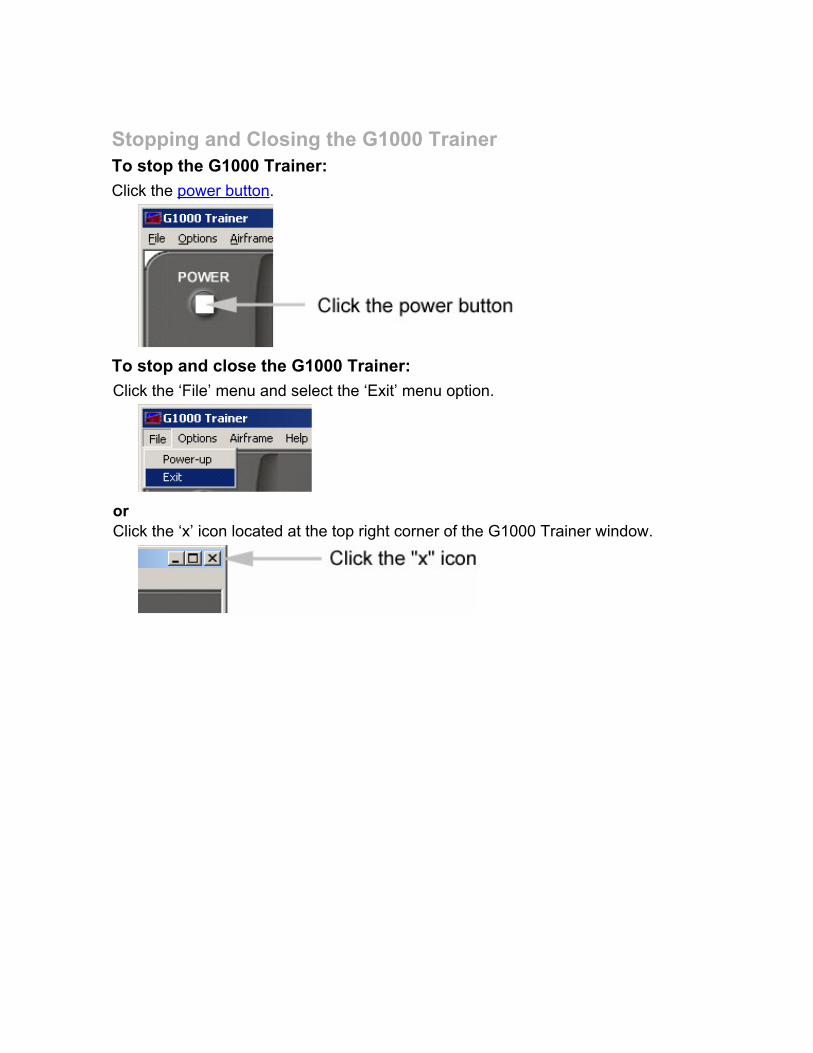
Stopping and Closing the G1000 TrainerTo stop the G1000 Trainer:
Click the power button.
To stop and close the G1000 Trainer:
Click the ‘File’ menu and select the ‘Exit’ menu option.
orClick the ‘x’ icon located at the top right corner of the G1000 Trainer window.

G1000 Trainer Control OverviewThe G1000 Trainer is operated via the following external controls:
External joystick, as indicated by the minimum system requirements
PC mouse
Keyboard

External JoystickThe external joystick is used to emulate pilot control inputs during flight.
A four-axis joystick with throttle/power and rudder control isrecommended for the G1000 Trainer.

PC MouseThe PC mouse is used to control the G1000 Trainer knobs, keys and softkeys.

Keyboard ShortcutsA number of G1000 controls can be activated on the G1000 Trainer, using keyboard shortcuts. Thefollowing shortcuts are available:
‘W’ activates the power button.
‘F1’ to ’F12’ respectively activate softkeys 1 through 12 (where softkey numbers are defined by theposition of the softkey from left to right on the display).
‘D’ activates the Direct-to key.
‘M’ activates the MENU key.
‘F’ activates the FPL key.
‘P’ activates the PROC key.
‘ESC’ activates the CLR key.
‘Enter’ (carriage return) activates the ENT key.
The space bar presses the FMS knob.
The arrow keys rotate the FMS knob as follows:
- Down arrow turns the large FMS knob clockwise (upper right arrow on the display).
- Up arrow turns the large FMS knob counterclockwise (upper left arrow on the display).
- Right arrow turns the small FMS knob clockwise (lower right arrow on the display).
- Left arrow turns the small FMS knob counterclockwise (lower left arrow on the display).
The number keys on the number keypad activate the bezel joystick used to pan the map.
The number keypad shortcuts are not available on laptop computers.
‘Alt’ + ‘F’ pulls down the ‘File’ menu
‘Alt’ + ‘O’ pulls down the ‘Options’ menu
‘Alt’ + ‘A’ pulls down the ‘Airframe’ menu
‘Alt’ + ‘H’ pulls down the ‘Help’ menu
‘N’ = ‘F11’ displays and hides the NRST window PFD only
‘Y’ = ‘F12’ displays and hides the ALERTS window PFD only

Configuring the External JoystickIf the external joystick is not already configured adequately to simulate pilot controlinputs on the G1000 Trainer, it can be configured by the user before systempower-up.
Joystick axis configuration can only be performed before the G1000system is powered up. If the joystick settings are changed while theG1000 system is powered up, the Trainer has to be restarted for thechanges to take effect.
To configure the joystick axes on the G1000 Trainer:
1. Click the ‘Options’ menu and select ‘Joystick Axis Configuration’.
2. Configure the external joystick axes as appropriate.
The external joystick axes should be configured according to thestandard pilot control inputs.

3. Click the ‘OK’ button.
The original external joystick axis configuration settings can be restoredby clicking the ‘Default Config’ button, then by clicking the ‘OK’ button onthe Joystick Axis Configuration window.

G1000 Trainer Bezel OverviewWith the exception of the power button (button which is not present on the G1000Control Display Unit), the G1000 Trainer bezel knobs, keys and softkeys are similarto and work in the same manner as those found on the G1000 system.
The G1000 Trainer bezel includes the following controls:
Power button
NAV VOL/ID knob
NAV Frequency Toggle key
NAV knob
HDG knob
ALT knob
COM knob
COM Frequency Toggle key
COM VOL/SQ knob
CRS/BARO knob
RANGE joystick
Direct-to key
MENU key
FPL key
PROC key
CLR key
ENT key
Dual FMS knob
12 softkeys

Knobs, Keys and SoftkeysThe G1000 Trainer bezel knobs, keys and softkeys are similar to and work in the same manner asthose found on the G1000 system.
The softkeys are located across the bottom of the display and are designed to perform variousfunctions depending upon the control display mode and the specific page being displayed.
Placing the mouse pointer over a key/softkey/knob and clicking it with the left mouse button is equivalentto pressing the key/softkey/knob of interest.In addition, arrows are displayed around the knobs of the G1000 Trainer bezel in order to enablesimulation of knob rotation.

Power ButtonAlthough the G1000 System does not feature a power button, such a button has been added tothe top left corner of the G1000 Trainer bezel for practical purposes.
Pressing the power button when the G1000 system is not running starts the system.Conversely, pressing the power button while the G1000 system is running stops thesystem.

AFCS ControlsThe AFCS Controls work with the PFD. Click the buttons to simulate selecting the controls on theG1000 Trainer.
The controls for your trainer may differ slightly. In addition, not all aircraft are equippedwith AFCS controls .
The AFCS Controls consist of the following:
1. HDG Key – Selects/deselects Heading Select Mode.
2. APR Key – Selects/deselects Approach Mode.
3. NAV Key – Selects/deselects Navigation Mode.
4. FD Key – Activates/deactivates the flight director in the default pitch and roll modes. If theautopilot is engaged, the FD Key is disabled.
5. XFR Key – Switches the autopilot between the pilot-side and the copilot-side flight directors.This selection also selects which air data computer is communicating with the activetransponder and which PFD triggers the altitude alert. Upon power-up, the pilot-side FD isselected.
6. ALT Key – Selects/deselects Altitude Hold Mode.
7. VS Key – Selects/deselects Vertical Speed Mode.
8. FLC Key – Selects/deselects Flight Level Change Mode.
9. CRS2 Knob – Sets the copilot-selected course on the HSI of PFD2 when the VOR1, VOR2, orOBS/SUSP mode is selected. Pressing this knob centers the CDI on the currently selectedVOR. The copilot-selected course provides course reference to the copilot-side flight directorwhen operating in Navigation and Approach Modes.
10. SPD Key – Switches the Flight Level Change Mode reference speed between IAS and MACHnumber.
11. NOSE UP/DN Wheel – Controls the active mode reference for the Pitch, Vertical Speed, andFlight Level Change Modes.
12. VNV Key – Selects/deselects Vertical Navigation Mode.
13. ALT SEL Knob – Sets the selected altitude in the Selected Altitude Box. In addition toproviding the standard G1000 altitude alerter function, selected altitude provides an altitudesetting for the Altitude Capture/Hold mode of the AFCS.

14. YD Key – Engages/disengages the yaw damper.
15. AP Key – Engages/disengages the autopilot.
16. BANK Key – Selects/deselects Low Bank Mode.
17. CRS1 Knob – Sets the pilot-selected course on the HSI of PFD1 when the VOR1, VOR2, orOBS/SUSP mode is selected. Pressing this knob centers the CDI on the currently selectedVOR. The pilot-selected course provides course reference to the pilot-side flight director whenoperating in Navigation and Approach Modes.
18. BC Key – Selects/deselects Back Course Mode.
19. HDG Knob – Sets the selected heading on the HSI. When operating in Heading Select mode,this knob provides the heading reference to the flight director.
The AFCS Controls work with the PFD. The Garmin Control Unit works with the MFD.

Garmin Control UnitThe controls for the MFD are located on both the MFD bezel and the Garmin Control Unit.
The controls for your trainer may differ slightly. In addition, not all aircraft areequipped with a Garmin Control Unit.
The controls for the Garmin Control Unit consist of the following:
1. Dual FMS Knob – Flight Management System Knob. This knob selects the MFD page tobe viewed; the large knob selects a page group (MAP, WPT, AUX, NRST), while thesmall knob selects a specific page within the page group. Pressing the FMS Knob turnsthe selection cursor ON and OFF. When the cursor is ON, data may be entered in theapplicable window by turning the small and large knobs. In this case, the large knobmoves the cursor on the page, while the small knob selects individual characters for thehighlighted cursor location.
2. Direct-to Key – Allows the user to enter a destination waypoint and establish a directcourse to the selected destination. (The destination is specified by the identifier, chosenfrom the active route, or taken from the map pointer position.)

3. FPL Key – Displays the active Flight Plan Page for creating and editing the active flightplan, or for accessing stored flight plans.
4. MENU Key – Displays a context-sensitive list of options. This list allows the user toaccess additional features or make setting changes that relate to particular pages.
5. PROC Key – Gives access to IFR departure procedures (DPs), arrival procedures(STARs) and approach procedures (IAPs) for a flight plan. If a flight plan is used,available procedures for the departure and/or arrival airport are automatically suggested.Theses procedures can then be loaded into the active flight plan. If a flight plan is notused, both the desired airport and the desired procedure may be selected.
6. Joystick – Changes the map range when rotated. Activates the map pointer whenpressed.
7. Alphanumeric Keys – Allow the user to enter data quickly, without having to selectindividual characters with the FMS Knob.
8. Plus (+) Minus (-) Key – Toggles a (+) or (-) character.
9. Decimal Key – Enters a decimal point.
10. SEL Key – The center of this key activates the selected softkey, while the right and leftarrows move the softkey selection box to the right and left, respectively.
40. ENT Key – Validates or confirms a menu selection or data entry.41. CLR Key – Erases information, cancels entries, or removes page menus. Pressing andholding this key displays the Navigation Map Page automatically.42. SPC Key – Adds a space character.43. BKSP Key – Moves the cursor back one character space.
The AFCS Controls work with the PFD. The Garmin Control Unit works with theMFD.
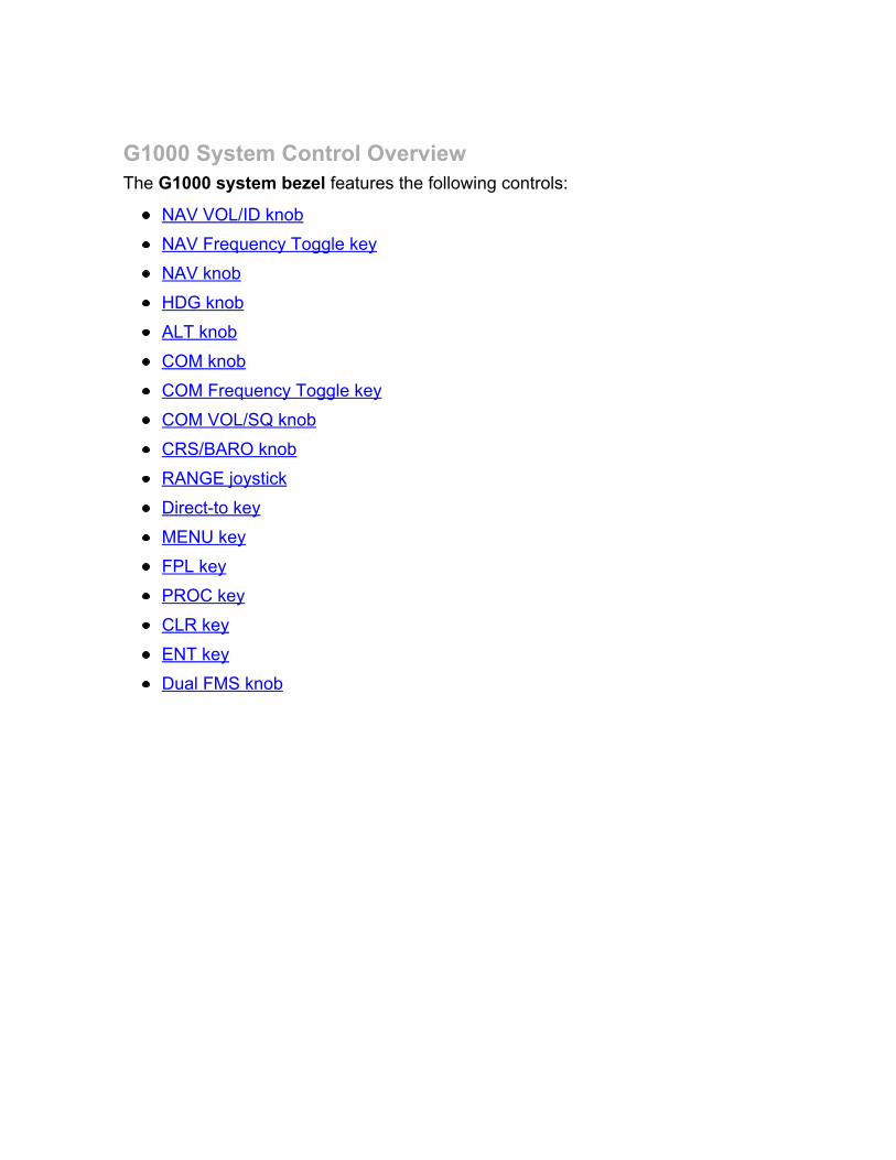
G1000 System Control OverviewThe G1000 system bezel features the following controls:
NAV VOL/ID knob
NAV Frequency Toggle key
NAV knob
HDG knob
ALT knob
COM knob
COM Frequency Toggle key
COM VOL/SQ knob
CRS/BARO knob
RANGE joystick
Direct-to key
MENU key
FPL key
PROC key
CLR key
ENT key
Dual FMS knob

NAV KnobThe dual NAV knob tunes NAV frequencies in the tuning box.
Turning the large NAV knob tunes the MHz portion the frequency.
Turning the small knob tunes the kHz portion of the frequency.
Pressing the NAV knob toggles the tuning box between the NAV radios.

NAV Frequency Toggle KeyThe NAV Frequency Toggle key toggles the NAV frequencies between the active and standbyfields.

NAV VOL/ID KnobThe NAV VOL/PUSH ID knob adjusts NAV radio volume level (turn) and turns the Morse codeidentifier ON and OFF (press).

HDG KnobThe HDG knob selects heading. When this knob is pressed, a window displaying digital headingappears momentarily to the left of the Heading indicator and the Heading bug is synchronizedwith the compass lubber line.

ALT KnobThe dual ALT knob is composed of both a large knob and a small knob and sets the referencealtitude.
The large knob sets the thousands of feet or meters.
The small knob selects the hundreds of feet or meters.
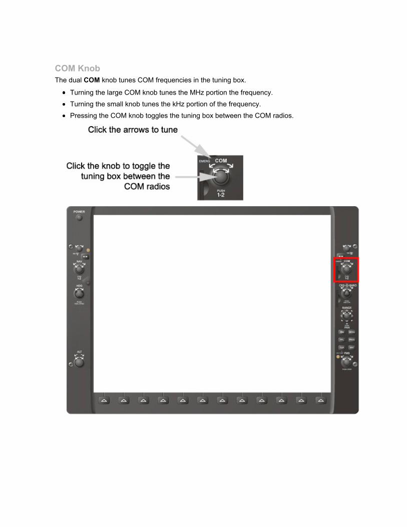
COM KnobThe dual COM knob tunes COM frequencies in the tuning box.
Turning the large COM knob tunes the MHz portion the frequency.
Turning the small knob tunes the kHz portion of the frequency.
Pressing the COM knob toggles the tuning box between the COM radios.

COM Frequency Toggle KeyThe COM Frequency Toggle key toggles the COM frequencies between the active and standbyfields.
Pressing and holding the COM Frequency Toggle key for approximately two secondstunes the emergency frequency (121.500) in the active COM field.

COM VOL/SQ KnobThe COM VOL/PUSH SQ knob adjusts COM radio volume level (turn) and turns automaticsquelch ON and OFF (press).

CRS/BARO KnobThe CRS/BARO knob is composed of both a large knob and a small knob.
The large knob (BARO knob) sets the altimeter.
The small knob (CRS knob) adjusts course.

RANGE JoystickThe RANGE joystick changes the map scale when rotated and activates the map pointer whenpressed.

Direct-to KeyThe Direct-to key enters a destination waypoint and establishes a direct course to this waypoint(the direct-to waypoint can be selected by its name identifier, from the active route, or from themap cursor position).

MENU KeyThe MENU key displays a context-sensitive list of options which allows the user to accessadditional features or make setting changes that relate to certain pages.

FPL KeyThe FPL key accesses the active Flight Plan Page; this page is used to create flight plans, editactive flight plans, or access stored flight plans.

PROC KeyThe PROC key selects departure, approach and arrival procedures from the database to add toa flight plan.

CLR KeyThe CLR key erases information or cancels data entry. When pressed and held, this key alsodisplays the Navigation Map Page (MFD only).

ENT KeyThe ENT key confirms selections and operations, and completes and approves data entry.

Dual FMS KnobThe dual FMS knob is used on the MFD and is composed of both a large knob and a smallknob.
The large knob selects a page group (MAP, WPT, AUX, NRST).
The small knob selects a specific page within the selected page group.
Pressing the FMS knob activates and deactivates the selection cursor on the selected page.When the selection cursor is activated, data may be entered using both the small knob and thelarge knob. In this case, the large knob moves the selection cursor on the page, while the smallknob selects individual characters for data entry.


Control Display ModesThe G1000 control display can be configured at any time—that is, whether the system is running or not—aseither a Primary Flight Display (PFD) or a Multi Function Display (MFD).
The G1000 control display can also be set at any time to reversionary mode, or backup mode, a mode in which allimportant flight information from both the PFD and the MFD is presented.

PFD ModeIn PFD mode, the control display presents information included in the six-packinstruments (that is, attitude, airspeed, altitude, vertical speed, heading, slip/skidand turn rate).
To configure the G1000 Trainer as a PFD:
Click the ‘Options’ menu and select the ‘PFD Mode’ menu option.
orRight-click anywhere on the control display and select ‘PFD Mode’.

MFD ModeIn MFD mode, the control display presents information associated both withnavigation and with the Engine Indication System (EIS).
To configure the G1000 Trainer as an MFD:
1a. Click the ‘Options’ menu and select the ‘MFD Mode’ menu option.
or1b. Right-click anywhere on the control display and select ‘MFD Mode’.

Reversionary ModeReversionary (or backup) mode is a mode of operation in which both the PFD andMFD are identically configured to display all of the important flight parameters inthe event of display failure.
To set the G1000 Trainer to Reversionary mode:
Click the ‘Options’ menu and select ‘Reversionary Mode’.
orRight-click anywhere on the control display and select ‘Reversionary Mode’.
Deselecting ‘Reversionary Mode’ returns the display to the normal displaymode that was selected before reversionary mode was activated (i.e.,either PFD or MFD).

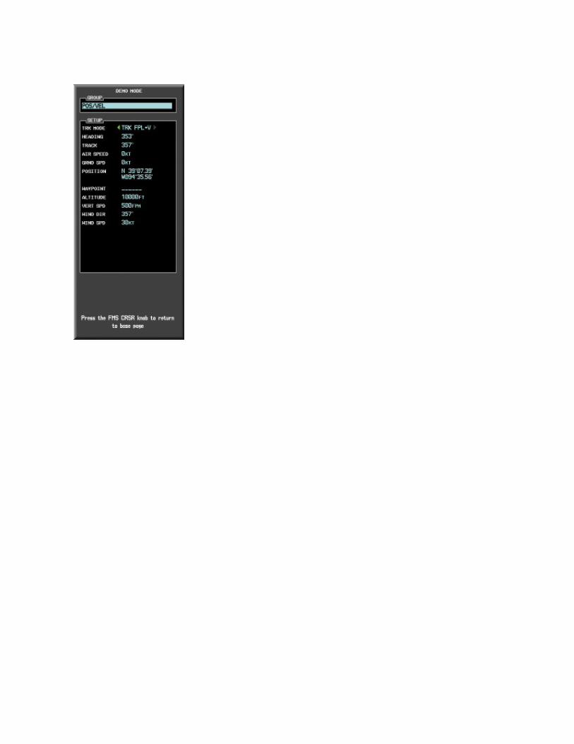
Demo ModeWhen no external joystick is connected to the PC, the G1000 Trainer operates inDemo mode.
In Demo mode, control inputs cannot be simulated in real time. However, anumber of flight parameters can be configured on the Demo Mode window in orderto allow flight simulation.
The Demo Mode window can be accessed in either PFD mode or MFDmode.

Accessing the Demo Mode WindowTo display the Demo Mode window:
Click the MENU key twice.
The demo mode options are divided into four sections:
POS/VEL – Settings related to speed, altitude, and position
GPS – Settings related to GPS solution and receiver type
SIMULATE FAILURE – Allows user to intentionally fail various parts of thesystem
OTHER – Other miscellaneous trainer settings


Flight ParametersIn Demo mode, flight can be simulated via a number of configurable flightparameters. The available configurable flight parameters are as follows:
TRK MODE
HEADING
TRACK
AIR SPEED
GRND SPD
POSITION
WAYPOINT
ALTITUDE
VERT SPD
WIND DIR
WIND SPD
GPS SOLUTION
RECEIVER
HPL FD
HPL WAAS
VPL WAAS
FUEL ONBOARD
FUEL FLOW
PC DATE/TIME
DATE
TIME
Track mode may be set to either ‘TRK FPL’, ‘TRK FPL + V’, or ‘MANUAL’. In TRKFPL (track flight plan) and TRK FPL + V (VNAV) modes, HEADING is setautomatically. Heading can only be changed when TRK MODE is set to ‘MANUAL’.

Setting the Flight Parameters (Demo Mode)To set the flight parameters for a flight in Demo mode:
1. Use the FMS knob and the ENT key to change the flight parameters in theDemo Mode window, as desired.
2. Press the FMS knob to close the Demo Mode window.

Simulating FailuresFailures of various parts of the G1000 system may be simulated at any time whilethe G1000 system is running by turning off the associated Line Replaceable Units(LRUs).
The tree-like layout of the Simulate Failures window demonstrates how somecomponents depend on others to function properly. For example, if both GIA1 andGIA2 are disabled, none of the components below them, such as COM1 or GPS2,will work.
To display various G1000 system failures:
1. Ensure that the control display is set to reversionary mode so as to allow thefull range of failures to be displayed.
2. Click the ‘Options’ menu (or right-click anywhere on the control display) andselect ‘Simulate Failures’.
or
1. Deselect the LRU(s) for which a failure is to be simulated and click ‘OK’.


Flight ScenariosBoth the practice exercises presented in the G1000 Pilot’s Training Guide andthe procedures included in the G1000 Multi Function Display Pilot’s Guide canhelp to provide the user with flight scenarios and may thus be followed tosimulate flights in G1000-equipped aircraft.

WFDE PredictionWFDE (WAAS and Fault Detection and Exclusion) Prediction detects and excludessatellite failures that can interrupt normal GPS navigation. When WFDE Predictionis performed prior to departure, it ensures that there is an adequate number ofworking satellites in the GPS constellation to navigate the specified route.
To use WFDE Prediction prior to departure:
1. Create a flight plan or activate a saved flight plan.
2. Run the WFDE Prediction program by selecting ‘Options’, then ‘WFDEPrediction Program’.
Your active flight plan is automatically imported into the WFDE Predictionprogram.

1. If necessary, change the flight plan details or de-select satellites.

2. View WFDE Prediction program results.

3. If necessary, update almanac data by selecting ‘Help’ on the WFDE PredictionProgram menu, then ‘Update Almanac’.

For more information on using WFDE Prediction in the G1000 Trainer, see theWFDE Prediction Program Instructional PFD on the G1000 Trainer installation discor at www.garmin.com.

Sound
The G1000 Trainer has the ability to play audio alerts. A sound card must beinstalled to hear the alerts.
To enable or disable audio alerts:
Choose ‘Options’ and check or uncheck ‘Enable Sound’.

Help MenuThe G1000 Trainer Help menu can be accessed at any time and contains thefollowing two options:
G1000 Trainer Help – activates the G1000 Trainer Help content.
About – displays the G1000 Trainer software application version number.

Minimum System RequirementsMinimum system requirements for the G1000 Trainer:
1.8 GHz processor
256 MB RAM
Windows® 2000 or XP
400 MB free hard disk space (1.4 GB free for FliteCharts™ option)
DVD-ROM drive
Microsoft® DirectX® 9.0c (software application included on the G1000 TrainerCD-ROM)
Video Card: DirectX-capable card with a minimum of 128 MB of memory andvideo card drivers that support DirectX 9.0c
Screen resolution: 1280 pixels wide x 1024 pixels high
Optional: Four-axis joystick with throttle/power and rudder control
Optional: Sound Card
Minimum system requirements for Dual Screen mode:
2.0 GHz processor
512 MB RAM
Windows® 2000 or XP
400 MB free hard disk space (1.4 GB free for FliteCharts™ option)
DVD-ROM drive
Microsoft® DirectX® 9.0c (software application included on the G1000 TrainerCD-ROM)
Video Card: DirectX-capable card with a minimum of 256 MB of memory andvideo card drivers that support DirectX 9.0c
Screen resolution: 1280 pixels wide x 1024 pixels high
Optional: Four-axis joystick with throttle/power and rudder control
Optional: Sound Card