30-0309 - boost/fuel pressure 15psi sae only...10-0309 inst, x-series boost/fuel pressure gauge 0 to...
TRANSCRIPT
P/N 30-0309X-SERIES GAUGE
BOOST/FUEL PRESSURE 15PSI SAEONLY
AEM Performance Electronics, 2205 126th Street Unit A, Hawthorne, CA 90250 - Phone: (310) 484-2322http://www.aemelectronics.com
STOP! - READ THIS BEFORE INSTALL OR USE!WARNING:
THIS INSTALLATION MAY REQUIRE WELDING OR INTEGRATION INTO A VEHICLE'S ELECTRICAL SYSTEM. DAMAGE
TO SENSITIVE ELECTRONICS, FIRE, OR EXPLOSION MAY OCCUR IF PROPER PRECAUTION IS NOT TAKEN. IF THERE
IS ANY DOUBT, DO NOT ATTEMPT THE INSTALLATION AND CONSULT A PROFESSIONAL.
NOTE: IT IS THE RESPONSIBILITY OF THE ENGINE TUNER TO ULTIMATELY CONFIRM THE CALIBRATION USE FOR
ANY PARTICULAR ENGINE IS SAFE FOR ITS INTENDED USE. AEM HOLDS NO RESPONSIBILITY FOR ANY ENGINE
DAMAGE THAT RESULTS FROM THE MISUSE OF THIS PRODUCT.
Instruction
Manual
The 52mm (2-1/16”) AEM X-Series Gauge features a four digit central readout and sweeping 24-color-coded LED display,providing immediate reference to the sensor reading in real-time. A 0-5V analog and an AEMnet (CAN bus) output isincluded and can be used with data loggers or aftermarket ECUs including the AEM Infinity Engine Management System(EMS).
Features
· 2-1/16" / 52mm outer diameter mounting· Flashing warn / alarm feature· Peak recall· Boost / fuel pressure reversible faceplate (SAE scaling
only)· Black bezel / "Boost/Fuel" faceplate supplied; Silver /
white available as optional purchase· Locking connectors· Supports vehicle / system voltages up to 16V· Auto-dimming display· 0-5V analog output· AEMnet (CAN bus) output
KIT CONTENTS
PN Description
10-0309 INST, X-SERIES BOOST/FUEL PRESSURE GAUGE 0 TO 15PSI
SAE ONLY
35-0309 GAUGE ASSY, X-SERIES BOOST/FUEL PRESSURE GAUGE 0 TO
15PSI SAE ONLY
35-4302 RED INSULATED BUTT CONNECTORS (6)
35-8618 NUT, KNURLED, M4x0.7 (2)
35-8614 BRACKET, X-SERIES GAUGE
35-8617 RUBBER BAND, X-SERIES GAUGE
35-3434 CABLE, X-SERIES GAUGE PWR/IO PRS
35-2131-15 SENSOR, 15 PSIG BRASS
35-2147 FITTING, 1/8" TEE
35-2151 1/8 NPT FEMALE TO 3/16 BARB ADAPTER
8-161-36 VACUUM HOSE, 7/64" x 36"
*OPTIONAL* ACCESSORIES
PN Description
30-0309-
ACC
BEZEL, X-SERIES GAUGE SILVER
FACEPLATE, X-SERIES BOOST 15PSI, WHITE
2
11/1/2016 - DOCUMENT NUMBER: 10-0309 © 2016 AEM Performance Electronics
30-0309 - BOOST/FUEL PRESSURE 15PSI SAE ONLY
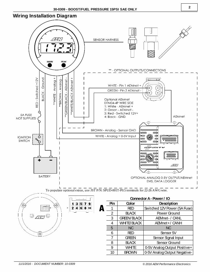
Wiring Installation Diagram
To populate optional extras, use JST P/N: SPUD-001T-P0.5 terminals for 22-26 AWG wire.
Connector A - Power / IO
Pin Color Description
1 RED Switched 12V Power (5A Fuse)
2 BLACK Power Ground
3 GREEN/BLACK AEMnet- / CANL
4 WHITE/BLACK AEMnet+ / CANH
5 NC NC
6 RED Sensor 5V
7 GREEN Sensor Signal Input
8 BLACK Sensor Ground
9 WHITE 0-5V Analog Output Positive+
10 BROWN 0-5V Analog Output Negative-

3
11/1/2016 - DOCUMENT NUMBER: 10-0309 © 2016 AEM Performance Electronics
30-0309 - BOOST/FUEL PRESSURE 15PSI SAE ONLY
OperationThe inner numeric LEDs and outer ring LEDs display the currently measured sensor reading; the inner numeric LEDs willflash when the sensor reading exceeds the (configurable) warn/alarm threshold value. WARN and PEAK buttons arelocated on the face of the gauge and are used to perform the following functions.
Display or adjust warn/alarm threshold§ Press the WARN button; the warn/alarm threshold will be displayed
and the outer LEDs will flash§ Use either the WARN or PEAK buttons to decrement or increment
the threshold value§ Depress and hold both the WARN and PEAK buttons until LESS or
GrTr appears§ Press the WARN button to toggle between LESS and GrTr modes
Warn/alarm activated when sensor reading is lessthan threshold valueWarn/alarm activated when sensor reading is greaterthan threshold value
§ The gauge will return to normal display mode a few seconds afterthe last button press
Display or clear stored peak value§ Press the PEAK button; the peak (highest) sensor reading will be
displayed and the outer LEDs will flash§ The peak value will be retained across power cycles§ While the peak value is being displayed, depress and hold the
PEAK button for three seconds until "CLr" appears to clear thepeak value
Will be displayed to confirm the peak value has beenreset
§ The gauge will return to normal display mode shortly after the lastbutton press
Sensor Installation
§ Install sensor with a liquid thread sealant suitable for NPT fittings.§ Remote mounting pressure sensors using flexible tubing and anti-vibration mounts will help extend sensor life. § Secure wiring to vehicle with wire ties paying special attention to the sensor harness routing beneath the vehicle and/
or in the engine compartment.§ Take care when routing the sensor harness near hot exhaust components, use strain reliefs and wire coverings as
appropriate.§ Use a 5A inline fuse on the switched 12V power supply line (Pin 1 - Power/IO).

4
11/1/2016 - DOCUMENT NUMBER: 10-0309 © 2016 AEM Performance Electronics
30-0309 - BOOST/FUEL PRESSURE 15PSI SAE ONLY
Faceplate / Bezel InstallationThe gauge kit is supplied assembled with a black faceplate and black bezel. An accessory kit is available (for purchasethrough AEM dealers) which includes an optional silver bezel and white faceplate. Please reference the OptionalAccessories section earlier in the document for the appropriate part numbers. Contact your dealer or visit www.aemelectronics.com for more information.
The faceplate may be reversible, displaying alternative scalings on either side. Reference the Operation section of thismanual for details on how to switch the display mode when reversing the faceplate. Disassembly is required to changethe faceplate, flip/reverse the faceplate, or change the bezel of the gauge. The following diagram will provide familiarizationwith the major components of the gauge prior to beginning the procedure.
Item Qty Description
1 1 Lens
2 1 Bezel
3 1 Faceplate
4 1 Diffuser
5 1 Light Guide
6 2 Button
7 2 Mounting Stud (M4 x 0.7)
8 3 Assembly Screw
9 1 Mounting Bracket
10 2 Brass Thumb Screw (M4 x 0.7)
11 1 Printed Circuit Board (PCB)

5
11/1/2016 - DOCUMENT NUMBER: 10-0309 © 2016 AEM Performance Electronics
30-0309 - BOOST/FUEL PRESSURE 15PSI SAE ONLY
Gauge Disassembly
STEP 1 - Remove the three assembly screws (8) using a #1 Phillips
head screwdriver. Separate the bezel (2) and cup (7) from the rest of the
assembly. If you have purchased the optional accessory kit, the silver
bezel may be replaced for the existing bezel at this time
STEP 2 - Separate the PCB (11) from the remaining components
STEP 3 - Slide the light guide (5) upward to remove it, the buttons may
fall out at this time - take care not to lose them
STEP 4 - As you separate the remaining components, diffuser (4),
faceplate (3), lens (1), note the order in which they were assembled.
The faceplate (3) may now be reversed to display an alternate scaling or
replaced for a different color as included in the optional accessory kit

6
11/1/2016 - DOCUMENT NUMBER: 10-0309 © 2016 AEM Performance Electronics
30-0309 - BOOST/FUEL PRESSURE 15PSI SAE ONLY
Gauge Assembly
STEP 1 - Place the light guide (5) on a flat surface (black side up) and
slide the buttons (6) into the slots
STEP 2 - Stack the diffuser (4), faceplate (3), and lens (1) in order, over
the buttons, and on to the light guide
STEP 3 - Reassemble the PCB and display stack with the bezel, making
sure screw holes are aligned through the entire assembly
STEP 4 - Reassemble and tighten screws to 2 in-lb (previously
assembled bezel) or 3 in-lb (new bezel). Do not over-tighten!

7
11/1/2016 - DOCUMENT NUMBER: 10-0309 © 2016 AEM Performance Electronics
30-0309 - BOOST/FUEL PRESSURE 15PSI SAE ONLY
Gauge Installation
Installation using supplied bracket Installation w ithout bracket, using rubber band
A 2-1/6" (52mm) hole is required to mount the X-Series gauge. A bracket and thumbscrews are provided to facilitateinstallation into a panel or gauge pod. In some cases, the gauge cup may be pushed into a mounting hole causing aninterference fit strong enough to retain the gauge; the supplied rubber band may be fit to the gauge to create a tighter fit inmounting holes slightly larger than 52mm. It is, however, recommended that gauges be mounted securely using thesupplied bracket to ensure they never become loose and cause a hazard during vehicle operation.
Note: The gauge is not water-proof and should not be installed in a location with exposure to water or snow. Damagecaused by water ingress will not be covered under warranty.
0-5V Analog OutputWHITE WIRE = Analog Positive +BROWN WIRE = Analog Negative -
0-5V Analog Output Scaling Formulas
psig = (3.75 * Volts) -1.88
bar = (0.26 * Volts) - 0.13
The 0-5V analog output is suitable for output to devices suchas loggers or ECUs. This differential output requires specialcare to ensure proper operation. The WHITE signal wireshould be connected to the positive of the analog input of thelogging device or ECU; the BROWN wire must be connectedto the negative of the analog input of the logging device orECU. If the logging device or ECU does not have adifferential analog input (both a dedicated positive andnegative terminal for the analog input) then connect theBROWN wire to the shared signal ground. If the device doesnot have a dedicated signal ground then as a last course ofaction, connect it to the power ground of the logging device.
Important Note: If bench testing the analog output outsideof a vehicle, a multimeter's positive lead may be connectedto the WHITE wire however the BROWN wire must beconnected to BOTH the multimeter's negative lead ANDpower ground going to the X-Series device. This connectionis usually made by the circuitry inside an ECU or datalogger.
0-5V Analog Output Scaling Table
Volts psig bar
<0.50 SENSOR ERROR
0.50 0.0 0.0
0.75 0.9 0.1
1.00 1.9 0.1
1.25 2.8 0.2
1.50 3.8 0.3
1.75 4.7 0.3
2.00 5.6 0.4
2.25 6.6 0.5
2.50 7.5 0.5
2.75 8.4 0.6
3.00 9.4 0.6
3.25 10.3 0.7
3.50 11.3 0.8
3.75 12.2 0.8
4.00 13.1 0.9
4.25 14.1 1.0
4.50 15.0 1.0
>4.50 SENSOR ERROR

8
11/1/2016 - DOCUMENT NUMBER: 10-0309 © 2016 AEM Performance Electronics
30-0309 - BOOST/FUEL PRESSURE 15PSI SAE ONLY
AEMnet (CAN bus) OutputWHITE WIRE WITH BLACK STRIPE = AEMnet+ / CANHGREEN WIRE WITH BLACK STRIPE = AEMnet- / CANL
The AEMnet output is suitable for output to AEM devices such as the AQ-1 data logger or Infinity ECU. The followingCAN configuration and message definition information is provided below to facilitate interface with third-party devices.
Bus TerminationAll AEMnet/CAN networks must be terminated to have anequivalent of approximately 60 Ohms of resistance. Generally, this means a 120 Ohm resistor connected inparallel to AEMnet+/AEMnet- (or CANH/CANL) at bothphysical ends of the bus run. The X-Series device does nothave any internal termination and is intended to beconnected to a pre-existing, properly terminated network. Please refer to the Bosch CAN2.0B specification for furtherdetail.
bit rate 500 kb/sec
format 29 bit ID
transmit rate 20 hz
terminating resistor none
endianness big / Motorola
DLC 8
Message ID 0x000A0309
Byte Bit Bitmask Label Data Type Scaling Offset Range
0 Pressure 16 bit unsigned 0.01 psig/bit 0 0 to 655.35 psig
1-7 - - - - - - -
FAQ / TroubleshootingWhat are the minimum wiring connections needed to use the gauge?Switched/fused 12V (RED) and power ground (BLACK) must be supplied to the 10 pin connector A and the sensor mustbe plugged into the harness. Any unused wires may be secured and fastened away for future use.
I installed my gauge correctly and the display just shows, "SEnS""SEnS" means that the gauge cannot read a valid signal from the sensor. Please ensure that the sensor is plugged inand that the wiring between the sensor and gauge is not damaged.
Can I extend the wires in my sensor harness?Yes, but match the existing wire gauge use of proper crimping/soldering techniques is required.
I want to add pins to the connector for the optional extra signals.To populate optional extras, use JST P/N SPUD-001T-P0.5 terminals for 22-26 AWG wire.
For support, contact AEM Technical Support at 1-800-423-0046 or [email protected].

9
11/1/2016 - DOCUMENT NUMBER: 10-0309 © 2016 AEM Performance Electronics
30-0309 - BOOST/FUEL PRESSURE 15PSI SAE ONLY
Specifications
Dimensions diameter (bezel) 2.40 / 61 in / mm
diameter (cup) 2-1/16 / 52 in / mm
depth (incl. bezel) 0.825 / 21 in / mm
depth (cup only) 0.200 / 5 in / mm
Sensor Installation past finger tight 1.5 - 3.0 turns
use liquid sealant
Supply Voltage min 7 VDC
max 18 VDC
Supply Current (13.8V) nominal 50.0 mA
Operating Temperature min -4 / -20 degF / degC
max (16V Supply) 185 / 85 degF / degC
Analog Output resolution 10 bit
update rate 500 hz
CAN 2.0B Output bit rate 500 kb/sec
format 29 bit ID
transmit rate 20 hz
terminating resistor none
endianness big / Motorola
DLC 8
12 Month Limited WarrantyAdvanced Engine Management Inc. w arrants to the consumer that all AEM High Performance products w ill be free from defects in material and
w orkmanship for a period of tw elve (12) months from date of the original purchase. Products that fail w ithin this 12-month w arranty period w ill be
repaired or replaced at AEM’s option, w hen determined by AEM that the product failed due to defects in material or w orkmanship. This w arranty is
limited to the repair or replacement of the AEM part. In no event shall this w arranty exceed the original purchase price of the AEM part nor shall
AEM be responsible for special, incidental or consequential damages or cost incurred due to the failure of this product. Warranty claims to AEM
must be transportation prepaid and accompanied w ith dated proof of purchase. This w arranty applies only to the original purchaser of product
and is non-transferable. All implied w arranties shall be limited in duration to the said 12-month w arranty period. Improper use or installation,
accident, abuse, unauthorized repairs or alterations voids this w arranty. AEM disclaims any liability for consequential damages due to breach of
any w ritten or implied w arranty on all products manufactured by AEM. Warranty returns w ill only be accepted by AEM w hen accompanied by a
valid Return Merchandise Authorization (RMA) number. Product must be received by AEM w ithin 30 days of the date the RMA is issued.
UEGO oxygen sensors are considered w ear items and are not covered under w arranty.
Please note that before AEM can issue an RMA for any electronic product, it is f irst necessary for the installer or end user to contact the EMS
tech line at 1-800-423-0046 to discuss the problem. Most issues can be resolved over the phone. Under no circumstances should a system be
returned or a RMA requested before the above process transpires.
AEM w ill not be responsible for electronic products that are installed incorrectly, installed in a non-approved application, misused, or tampered
w ith.
Any AEM electronics product can be returned for repair if it is out of the w arranty period. There is a minimum charge of $50.00 for inspection and
diagnosis of AEM electronic parts. Parts used in the repair of AEM electronic components w ill be extra. AEM w ill provide an estimate of repairs
and receive w ritten or electronic authorization before repairs are made to the product.