36kv gas insulated medium voltage switchgear · 5 1 general 1.1overview secocube is an innovative...
TRANSCRIPT

GE Industrial Solutions
36kVGas Insulated Medium Voltage SwitchgearUser Manual

1
Safety first!
Important recommendations:
Switchgear should be installed in a clean, dry, ventilated room suitable for electrical equipment.
Installation, operation and maintenance should be carried out by licensed electricians.
Fully comply with the applicable standards (e.g. IEC or national standards), the utility connection
requirements and the applicable safety regulations.
Observe the relevant instructions in the instruction manual for all actions in relation to switchgear.
Pay attention to the hazard notes in the instruction manual marked with this warning symbol.
Make sure that the operating limits of the switchgear are not exceeded.
Keep the instruction manual accessible to all personnel involved in installation, operation and maintenance.
The users must act responsibly in all matters affecting safety at work and correct handling of the
switchgear.
Should you have any questions about this instruction manual, our field team will be pleased to provide the
required information.
GE Energy reserves the right to correct any errors or omissions regarding this document. Check that the latest
version of this document.
WARNING
Always follow the instruction manual and respect the rules for good engineering
practice! Hazardous voltage can cause electrical shocks and burns.
Disconnect power, then earth and short-circuit before proceeding with any work
on the equipment!

2
Content 1 General ...................................................................................................................................... 5
1.1Overview ................................................................................................................... 5
1.2 Product Type ............................................................................................................ 5
1.3 Operating Conditions .............................................................................................. 5
1.3.1 Normal Operating Conditions ................................................................................................. 5
1.3.2 Special Operating Conditions ................................................................................................. 6
1.4 Standard and Specification ..................................................................................... 6
2 Technical Specification ....................................................................................................... 7
3 Configuration .......................................................................................................................... 8
3.1 SecoCube Configuration .......................................................................................... 8
3.2 Insulated Gas System .............................................................................................. 9
3.2.1 Monitor SF6 Gas Pressure ....................................................................................................... 9
3.2.2 Limitation of Internal Arc fault .............................................................................................. 10
3.2.3 Design And Description Of Arc Duct ..................................................................................... 11
3.3 SecoVac-G Embedded Pole Vacuum Circuit Breaker ........................................... 13
3.3.1 Function ................................................................................................................................. 13
3.3.2 Circuit Breaker Specification ................................................................................................. 14
3.3.3 Configuration of SecoVac-G ................................................................................................. 17
3.3.4 Principle of Arc Extinguishing ............................................................................................... 18
3.3.5 Charging The Mechanism ..................................................................................................... 18
3.3.6 Closing Operation .................................................................................................................. 19
3.3.7 Opening Operation ................................................................................................................ 20
3.4 IST Three-position Disconnector ........................................................................... 20
3.4.1 Three-positionSwitch Specification ...................................................................................... 21
3.4.2 Earthing Function In Conjunction With The Vacuum Circuit Breaker ................................. 22
3.4.3 Motor Operation of 3-position Disconnector ....................................................................... 22
3.4.4 Manual Operation of 3-position Disconnector .................................................................... 23
3.5 Locking Operation ................................................................................................. 25
3.6 HV Components Connection ................................................................................. 26
3.6.1 Cable Connection .................................................................................................................. 26
3.6.2 Busbar Connection ................................................................................................................ 26
3.7 Secondary System For Controlling And Monitoring ............................................. 27
3.8 Interlocking ............................................................................................................ 27
3.8.1 Overview ................................................................................................................................ 27
3.8.2 Interlocks Between Circuit Breaker And 3-position Disconnector ...................................... 28
3.9 Earthing The Tee-off Busbar.................................................................................. 29
3.9.1 Motor-driven Earthing Operation of Three-position Disconnector ..................................... 29

3
3.9.2 Manual Operation of Release The Tee-off Earthing ............................................................ 29
3.10 Earthing The Main Busbar ................................................................................... 30
3.10.1 Earthed By Main Busbar Earthing Panel ............................................................................ 30
3.10.2 Earthing By Main Busbar Sectionaliser / Disconnector Panel .......................................... 32
3.11 Testing Process and Testing Equipment ............................................................. 32
4 Packing, Delivery and Storage ...................................................................................... 34
4.1 Conditions on Delivery ........................................................................................... 34
4.2 Packing .................................................................................................................. 34
4.3 Transportation ....................................................................................................... 34
4.4 Upon Receipt ......................................................................................................... 35
4.5 Storage ................................................................................................................... 35
5. Switchgear On-site Installation ................................................................................... 37
5.1 On-site Conditions ................................................................................................. 37
5.2 Floor Preparation ................................................................................................... 37
5.3 Note of On-site Installation ................................................................................... 39
5.4 Installation Foundation ......................................................................................... 39
5.5 Panel Installation and Extension ........................................................................... 43
5.5.1 Preparation before installing ................................................................................................ 44
5.5.2 Panel Installation ................................................................................................................... 44
5.6 Install Other HV Plug-in Components And Secondary Wiring ............................. 50
5.6.1 HV Cable Installation ............................................................................................................. 51
5.6.2 VT, SA and End Plug Installation ........................................................................................... 51
5.6.3 Fuse Installation and Replacement of the VT Panel ............................................................ 52
5.6.4 Secondary Wiring .................................................................................................................. 57
5.7 Final Inspection ...................................................................................................... 59
5.8 Arc Duct Installation .............................................................................................. 59
6. Commissioning and Operation ..................................................................................... 64
6.1Commissioning ....................................................................................................... 64
6.1.1Preparation ............................................................................................................................. 64
6.1.2 Initial start-up ........................................................................................................................ 64
6.2 Switchgear Operations .......................................................................................... 65
6.2.1Circuit breaker ........................................................................................................................ 65
6.2.2Three-position disconnector .................................................................................................. 65
6.3 Observation, Checking and Monitoring ................................................................ 65
6.3.1 Monitor SF6 Gas Tank ............................................................................................................ 65
6.3.2 Electrical/mechanical Display and Monitoring .................................................................... 66
6.4 Test Procedures ..................................................................................................... 66
4
6.4.1 Main Circuit Power-off Test ................................................................................................... 66
6.4.2 Main Circuit Phase Sequence Test ........................................................................................ 66
6.4.3 High Voltage Tests ................................................................................................................. 67
6.4.4 Current Test ........................................................................................................................... 68
6.5 Safety Instructions For Voltage Transformer Operation ...................................... 68
7. Maintenance, Repair and Recycling ........................................................................... 69
7.1 General ................................................................................................................... 69
7.2 Inspection And Maintenance................................................................................. 69
7.2.1 Vacuum Circuit Breaker ........................................................................................................ 69
7.2.2 Three-position Disconnector ................................................................................................ 70
7.2.3 Insulating Gas And Its Maintenance..................................................................................... 70
7.3 Instruction for dispatching the gas and refilling the gas ..................................... 70
7.4 Maintenance and Components Replacement ...................................................... 74
7.5 Spare Parts and Auxiliary Materials ...................................................................... 75
7.6 Recycling Regulations ........................................................................................... 75
8. Notice ..................................................................................................................................... 76
8.1 Gas system ............................................................................................................ 76
8.2 Connection of HV Plug-in Components ................................................................ 76
8.3 About Interlocking ................................................................................................. 77

5
1 General
1.1Overview
SecoCube is an innovative cubicle gas-insulated switchgear platform provided by GE Energy. It perfectly
combines HV gas insulated technology and MV metal enclosed technology together. All the high voltage
parts, such as circuit breaker, disconnector, busbar etc. are effectively sealed in a stainless steel gas tank
filled with high performance insulated gas; provide customer a compact, modular, smart, high
performance and maintenance free switchgear.
With modern digital manufacturing, automatic testing, sensing, monitoring and protection technology,
SeocCube provides perfect solutions for power distribution network, especially for metro, tunnel, railway,
airport, mining, O&G, wind farm, and urban power grid substations, requiring high reliability.
1.2 Product Type
1.3 Operating Conditions
1.3.1 Normal Operating Conditions
The switchgears are fundamentally designed for the normal service conditions for indoor switchgears to
GB 3906-2006 and the IEC 62271-200:2003.
Ambient temperature
- Maximum +40℃
- Minimum -25℃
- Daily average maximum temperature +35℃
The maximum site altitude is 1000 m above sea level
Humidity
- Daily average relative humidity≤95%

6
- Monthly average relative humidity≤90%
- Daily average air pressure≤2.2×10⁻³MPa
- Monthly average air pressure≤1.8×10⁻³MPa
The ambient shall not suffer obvious pollution caused by corrosive, flammable or explosive gas.
Electromagnetic interference in the secondary system shall be less than 1.6kV.
Pollution level is more than class II identified by IEC 507:1991
1.3.2 Special Operating Conditions
High altitude ( >1000m a.s.l. ) SecoCube is available. Special operating conditions apply, please contact GE
in advance.
In accordance with IEC 62271-1, the manufacturer and end-user must agree about special operating
conditions which deviate from operation under normal conditions. The manufacturer/ supplier must be
consulted in advance if especially severe operating conditions are involved.
1.4 Standard and Specification
SecoCube complies with the standards and specifications for factory-assembled, metal enclosed and type
tested high voltage switchgear to IEC publications as given below.
IEC62271-200 (GB3906) High-voltage switchgear and controlgear – Part 200: AC metal-enclosed switchgear
and controlgear for rated voltages above 1kV and up to and including 52 kV
IEC62271-100 (GB1984) High-voltage switchgear and controlgear – Part 100: High-voltage
alternating-current circuit-breakers
IEC62271-1 (GB/T11022) The Common specifications for high-voltage switchgear and control gear standards
IEC62271-102 (GB1985) High-voltage switchgear and controlgear – Part 102: Alternating-current
disconnectors and earthing switches
IEC 60480 (GB8905) Guidelines for the checking and treatment of sulfur hexafluoride (SF6) taken from
electrical equipment and specification for its re-use
IEC 62271-303 (GB 28537) Test guide of SF6 gas tightness for high-voltage switchgear
IEC 60376 (GB 12022) Sulphur hexafluoride for industrial use
DL/T 593 Common specifications for high-voltage switchgear and controlgear
DL/T 404 Indoor AC High Voltage Switchboard Ordering requirement
All other corresponding IEC publications, national or local safety regulations must be followed during the
installation and operation of the switchgear. In addition, any project specific advice from GE must be
considered.

7
2 Technical Specification
General
Rated voltage kV 27/24/17.5/13.8 36
Rated power frequency
withstand voltage (1min)
To earth/phase to
phase
kV 95*(1) 95*(1)
Across isolating
distance
kV 118*(1) 118*(1)
Rated lightning impulse
withstand voltage
To earth/phase to
phase
kV 185*(1) 185*(1)
Across isolating
distance
kV 215*(1) 215*(1)
Rated frequency Hz 50/60 50/60
Rated current A 1250, 2500*(2) 1250, 2500*(2)
Single capacitor bank breaking capacity A 400 *(3) 400 *(3)
Rated cable charging breaking current A 50 50
Rated shortcircuit breaking current kA 31.5 31.5
Rated short circuit making current(peak) kA 82 82
Rated short time withstand current and
endurance time
kA/s 31.5/3s 31.5/3s
Rated peak withstand current kA 82 82
Operating Sequence O-0.3s-CO-180s-CO
O-0.3s-CO-15s-CO
O-0.3s-CO-180s-CO
O-0.3s-CO-15s-CO
Gas System
Insulated gas 50%SF6+50%N2 50%SF6+50%N2
Annual leakage rate %/Y ≤0.1 ≤0.1
Rated gas pressure (abs, 20˚C) MPa 0.12 0.12
Alarm pressure (abs, 20˚C) MPa 0.11 0.11
Minimum operating pressure (abs, 20˚C) MPa 0.10 0.10
Degree of protection
Gas tank IP65 IP65
Enclosure IP4X IP4X
Dimensions and weight
Dimensions(W×D×H) 1250A mm 600×1500×2400 600×1500×2400
Dimensions(W×D×H) 2500A mm 800×1500×2400 800×1500×2400
Weight 1250A kg 800 ~ 1000 800 ~ 1000
Weight 2500A kg 1100 ~ 1400 1100 ~ 1400
* (1) Can maintain the rated insulation level at 0.00 MPa (rel.) SF6 pressure.
* (2) 2300A at 60Hz
* (3) At 50Hz

8
3 Configuration
VCB gas tanks and main busbar gas tank are manufactured of 3 mm stainless sheet by laser cutting and laser welding process. The enclosure, framework, sidewalls and base are manufactured of 2mm galvanized steel sheet and assembled by bolts. Front cover and side cover of end panel are made of high-quality cold-rolled steel sheet with painting process, which provides an excellent corrosion-proof capability.Personnel can access the cable compartment to install or maintenance HV cables after removing the cable compartment cover.
3.1 SecoCube Configuration
1. Protection and control unit2. LV compartment3. VCB mechanism4. SecoVac-G Embedded pole vacuum circuit breaker5. LV compartment door6. Gas density indicator7. VCB gas tank8. 3-position switch mechanism9. 3-position switch10. Main busbar11. Main busbar gas tank12. Front cover13. Surge arrester14. Pressure relief device of main busbar gas tank15. Inner-cone cable bushing16. Cable terminal17. Cables18. Rear cover19. Pressure relief device of VCB gas tank20. CT
Figure 3.1 SecoCube configuration

9
Warning:
Do not allow to force open the cable compartment door when the panel is engaged, otherwise it
will damage the electrical interlocking and defeat the security.
The main components of SecoCube include SecoVac-G vacuum circuit breaker, IST three-position
disconnector, CTs, plug-in VT, plug-in arrester, main busbar system, cable terminal etc. Protection and
control device are installed in LV compartment. The main busbar connection between panels can be
completed through plug-in busbar connectors.
SecoCube-40.5 offers the single busbar solutions as follows:
- Incoming and outgoing feeder panels
- Bus sectionalizer panel
- Disconnect/riser panel
- VT + Surge arrester panel
- Metering panel
- Above functional panels with multiple cables incoming or outgoing in parallel.
3.2 Insulated Gas System
All high voltage live components are completely sealed inside the gas tanks and independent of
environmental influence.
Each gas tank has its independent gas system and pressure relief device. Gas density sensor and/or
pressure gauge can be fitted. The gas tank of each panel is independent to each other. Desiccant bags are
placed in every gas tank.
The insulation gas is maintenance free under normal operating conditions.
3.2.1 Monitor SF6 Gas Pressure
Each gas tank is equipped with a temperature compensated gas pressure gauge (density indicator or
density monitor on request) to indicate its inner pressure.
In case the pressure inside the tank falls below the preset alarming pressure, the density monitor will give
an alarm signal or trip the circuit breaker.
Compared with density monitor
SecoCube can maintain the rated insulation level at 0.00 MPa (rel.) SF6 pressure.

10
Figure 3.2 Temperature compensated pressure gauge (standard)
* Compared with gas density indicator and gas density monitor, pressure gauge doesn’t have function to send alarm signal.
Figure 3.3 Gas density indicator (Optional)
* When a gas density indicator is fitted, operator can monitor the gas pressure both locally and remotely.
Figure 3.4 Gas density monitor (Optional)
* Without local indicator, Gas density monitor is used to monitor the gas pressure remotely.
3.2.2 Limitation of Internal Arc fault
In the event of internal arc fault, the gas density indicator/monitor could give out signal to the relay to trip
the circuit breaker.

11
Each gas tank of SecoCube is equipped with a pressure relief device. If an internal arc fault occurs, and the
actual pressure exceeds its designed pressure, the pressure relief device will open, allowing the pressurized
gas flowing to the pressure relief channel at the top or bottom of the switchgear, to release the pressure.
Thus ensures the safety of the equipment and personnel.
Figure 3.5 Pressure relief device
3.2.3 Design And Description Of Arc Duct
An arc fault is a fault in which the current flow is through the air as opposed to a short circuit faults where
in the solid connection between the conductors causes the current to flow. The arc fault can happen due to
many reasons like improper usage of equipment or aging of parts. Arc faults cause both personnel hazard
and significant economic losses due to damage to equipment and interruption of process. The damage is
caused due to the let through energy through the fault which develops enormous amount of pressure, heat
etc.
In the unlikely event of an internal arc fault, the pressure generated inside is guided into the pressure relief
ducts through the pressure relief vents.
The switchgear panel is designed to sustain the internal arc fault in main busbar, breaker and cable
compartments independently. The switchgear has provided the arc ducts on the side walls of the panel to
channel out the gases generated during the internal arc fault inside the compartments to the outside of
the switchgear panel in order to prevent the damages in the panel and to the operating personnel.
In case of an arc fault in circuit breaker tank, the pressure relief vent opens and guides the pressure
outside through the arc duct installed on the side walls of the panel. (Refer Figure 3.5)

12
Figure 3.6: Channeling out of gases from breaker tank through arc duct
In the event of an internal arc fault in main busbar tank, the pressure relief vent in main busbar tank
opens to guide the pressure outside through the installed arc duct on the side walls of the panel (Refer
Figure3.6)
Figure 3.7: Channeling out of gases from main busbar tank through arc duct
In the case of an arc fault in cable compartment, the pressure relief flap opens in the pressure relief
Front end
Busbar and cable compartment
release channel

13
duct and the gases are channeled out through the duct. Figure 3.7.
Figure 3.8: Channeling out of gases from cable compartment through arc duct
From the figures shown above, it can be observed that the arc duct is installed on the side walls of the
panel which is in green color. The arrows are marked to show the gases been channeling out.
The pressure relief disks are provided for both the breaker tank and the main busbar tank. In case of arc
fault happens in breaker tank, the pressure relief disk in breaker tank opens and the gas is guided to arc
duct through the top (as shown in Figure 3.5), while arc fault happens in main busbar tank, the pressure
relief vent opens and it releases the gas through arc duct from bottom of the panel (as shown in Figure 3.6).
3.3 SecoVac-G Embedded Pole Vacuum Circuit Breaker
3.3.1 Function
SecoVac-G vacuum circuit breaker performs the following functions:
Making and breaking the load current.
Making and withstanding the short circuit fault current.
Breaking the fault current, such as short circuit current.
The embedded poles inside SecoVac-G vacuum circuit breaker are arranged vertically into the circuit
breaker gas tank. The operating mechanism is mounted outside the gas tank, convenient for maintenance.
The mechanical endurance of SecoVac-G is 10000 operations.
Rear end

14
3.3.2 Circuit Breaker Specification
SecoVac-G Vacuum Circuit breaker
General
Rated voltage kV 27/24/17.5/13.8 36
Rated insulation level *(2)
Rated power
frequency
withstand voltage
(1min)
kV 95*(1) 95*(1)
Rated lightning
impulse withstand
voltage
kV 185*(1) 185*(1)
Rated frequency Hz 50/60 50/60
Rated current A 1250, 2500*(2) 1250, 2500*(2)
Single capacitor bank breaking capacity A 400 *(3) 400 *(3)
Rated cable charging breaking current A 50 50
Rated shortcircuit breaking current kA 31.5 31.5
Rated short circuit making current(peak) kA 82 82
Rated short time withstand current and
endurance time
kA/s 31.5/3s 31.5/3s
Rated peak withstand current kA 82 82
Electrical endurance times 274 (Class E2) Class E1
Operating Sequence O-0.3s-CO-180s-CO
O-0.3s-CO-15s-CO
O-0.3s-CO-180s-CO
O-0.3s-CO-15s-CO
Mechanical Characteristic
Closing time (Rated operating voltage) ms 50 ~ 80 50 ~ 80
Opening time (Rated operating voltage) ms 25 ~ 40 25 ~ 40
Mechanical endurance times 10000 (Class M2) 10000 (Class M2)
Rated voltage of auxiliary circuit V
DC 24, 30, 36, 48, 60,
110, 125, 220;
AC 110, 125, 220, 240
DC 24, 30, 36, 48, 60,
110, 125, 220;
AC 110, 125, 220, 240
Opening speed m/s 1.4 ~1.9 1.4 ~1.9
Closing speed m/s 0.6 ~1.3 0.6 ~1.3
Clearance between open contacts mm 19±1.0 19±1.0
Bouncing time during closing ms 3 2
Asynchronous time during closing ms 2 2
Asynchronous time during opening ms 2 2
* (1) Can maintain the rated insulation level at 0.00 MPa (rel.) SF6 pressure.
* (2) 2300A at 60Hz
* (3) At 50Hz

15
Motor
The spring charge motor will be charged automatically after each closing
operation of the circuit breaker.
Manual charging carried out by plugging the charging handle is only used when
auxiliary power supply is out of service.
Rated Voltage (kV) Normal Operation Voltage
Scope
Energy Storing Period Under
Rated Operation Voltage (S)
Input Power (W)
DC110 85% ~110% ≤10 90
DC220 85% ~110% ≤10 90
AC110 85% ~110% ≤10 90
AC220 85% ~110% ≤10 90
DC125 85% ~110% ≤10 90
DC60 85% ~110% ≤10 90
DC48 85% ~110% ≤10 90
Closing Trip Coil
While energized, the closing trip coil is tripped to release the spring energy and
close the circuit breaker.
Rated Voltage (kV) Normal Operation
Voltage Scope
Rated Current (A) Input Power (W)
DC 24 80% ~ 110% 11.86 220
DC 30 80% ~ 110% 10.78 220
DC 36 80% ~ 110% 8.84 220
DC 48 80% ~ 110% 5.97 220
DC 60 80% ~ 110% 3.55 220
DC 110 80% ~ 110% 1.92 220
DC 125 80% ~ 110% 1.73 220
DC 220 80% ~ 110% 1.07 220
AC 110 85% ~ 110% 1.92 220
AC 125 85% ~ 110% 1.73 220
AC 220 85% ~ 110% 1.07 220

16
Opening Trip Coil
Opening trip coil is tripped by protection relay or control device to open the circuit
breaker.
Rated Voltage (kV) Normal Operation
Voltage Scope
Rated Current (A) Input Power (W)
DC 24 65% ~ 120% 11.86 220
DC 30 65% ~ 120% 10.78 220
DC 36 65% ~ 120% 8.84 220
DC 48 65% ~ 120% 5.97 220
DC 60 65% ~ 120% 3.55 220
DC 110 65% ~ 120% 1.92 220
DC 125 65% ~ 120% 1.73 220
DC 220 65% ~ 120% 1.07 220
AC 110 85% ~ 120% 1.92 220
AC 125 85% ~ 120% 1.73 220
AC 220 85% ~ 120% 1.07 220
Anti-pumping Device
If constant CLOSE and OPEN commands are present at the vacuum circuit-breaker at the same time, the
vacuum circuit-breaker will return to the open position after closing. It remains in this position until a new
CLOSE command is given. In this manner, continuous closing and opening (pumping) is avoided.

17
3.3.3 Configuration of SecoVac-G
Figure 3.9 SecoVac-G vacuum circuit breaker
The vacuum interrupter of the VCB is of an optimized design, the ceramic insulator is compact with high
insulation level and a high current breaking capability. The contacts are made of Copper-Chromium, with
excellent abrasion resistance, long electrical endurance, and high short circuit breaking capacity.
The embedded poles are assembled on the flange plate of the frame. The vacuum interrupter and terminals
are fixed inside the embedded pole by APG epoxy moulding process.
1. Embedded pole
2. Sealing gasket
3. Insulating coupling rod
4. O-ring gasket
5. Pilot pin
6. Opening spring
7. Main shaft
8. Adjustable nut
9. 4-level mechanism
10. Closing solenoid
11. Closing lever
12. Closing half-shaft
13. Retention stop
14. Closing spring
15. Charging lever
16. Charging shaft
17. Transmission gear
18. Charging motor
19. Cam
20. Trip lever
21. Latching plate
22. Opening half shaft
23. Opening lever
24. Opening solenoid

18
The vacuum circuit breaker is equipped by a modularized spring-charging mechanism, which can be
operated manually or electrically. Thanks to the optimized design, fewer components are used and high
reliability is realized.
The VCB enclosure also serves as the frame for the operating mechanism. The enclosure is divided into five
sections by four pre-assembled plates of the opening and closing modules. The transmission, charging,
tripping, closing and damping device are mounted inside. Opening and closing the circuit breaker is
realized by controlling the main shaft.
The embedded poles with vacuum interrupter inside and operating mechanism are assembled as a whole
part, which simplify the transmission device and optimize the mechanical characteristics. Such design
reduces the energy consumption and improves the mechanical reliability.
3.3.4 Principle of Arc Extinguishing
The arc inside the vacuum interrupter is extinguished by axial magnetic field (AMF) principle. The vacuum
interrupter has a very high vacuum degree and a very low contact resistance.
When the VCB breaks normal load current or fault current in the serving power system, vapour arc arises
between the moving and fixed contacts. There will be axial magnetic field between the open contacts
which makes the arc moving around the contact surface with low arc voltage. The arc is extinguished at
the first natural zero of the alternating current after switch-off, while the ion, electron and metal vapour
will polymerize together to re-establish a high dielectric strength between the contacts. Then the current
flow is securely interrupted.
3.3.5 Charging The Mechanism
The mechanism can be charged manually or electrically.
In electrical charging procedure, the charging shaft (16) will be driven by the sprocket under the control of
the torque output of the charging motor. Then the charging lever (15) will move to charge the closing
spring.
When the closing spring charging is completed, the energy is retained by the retention stop(13).At the same
time, the cam(19) push the lever to drive the micro switch in order to switch off the power supply of the
motor. Then the position indicator on the circuit breaker panel shows “charged”.
The motor (18) will finish its charging automatically after each closing of the circuit breaker in electrical
operation procedure.
Manual charging will be carried out by plugging the charging handle (Figure 3.10) into the aperture. Push
the handle up and down repeatedly until hearing a “clicking” sound, and then the spring is fully charged.

19
Figure 3.10 Front panel of SecoVac-G VCB Figure3.11 Manual charging handle of the VCB
Note: Once the operator fell the gear or handle have gotten the power, approximately 15 cycles up and
down will finish the charge operation.
3.3.6 Closing Operation
When receive the closing signal after the mechanism is charged, the closing solenoid (10) will be energized
and move forward. Driven by the closing lever (11), the closing half shaft (12) turns and release the
restriction conducted by the retention stop (13) on the charging shaft (16). The closing spring (14) will
release the charged energy and drive the charging shaft(16) and cam(19) to turn clockwise. The main
shaft(7) will be driven by its driving lever and the cam(19) to make the insulating coupling rod inside the
embedded pole moving upward to close the circuit breaker by controlling the 4-level mechanism(9). Then
the position indicator on the circuit breaker panel shows “I” (as shown in Figure 3.11(a)).
Manual closing can be realized by pressing the ”I” button in green on the front panel of the circuit breaker
(as shown in Figure 3.11(b)).
(a) (b)
Figure 3.12 SecoVac-G front panel

20
3.3.7 Opening Operation
When receive the opening signal after the closing operation is completed, the opening solenoid (24) will be
energized and move forward. Driven by the opening lever (23), the opening half shaft (22) turns to make the
main shaft (7) turn clockwise under the force of the opening spring (6) and the closing spring.
The main shaft (7) drives the 4-level mechanism (9) to move. The insulating coupling rod (3) pulls the
insulating rod of the vacuum interrupter downward to open the circuit breaker. Then the position indicator
on the circuit breaker panel shows “O”.
Manual opening can be realized by pressing the ”O” button in red on the front panel of the circuit breaker
(as shown in Figure 3.12).
Figure 3.13 SecoVac-G front panel
3.4 IST Three-position Disconnector
The three-position disconnector inside the SecoCube is of straight-moving design and driven by motor via
insulation spindle. A moving contact assembly makes the natural interlocks between three stable positions
as follows:
Connect to the main busbar (Closed)
Disconnect from the main busbar (Open)
Connect to the earthing contacts (Earthed)
Figure 3.14 IST three-position disconnector and its operating handle

21
Closed Disconnect Earthed
Figure 3.15 Three positions of the IST switch
The earthing position can be cancelled or blocked on request, so that two-position disconnector is realized.
Operating mechanism of three-position disconnector is mounted in the low voltage compartment outside
the gas tank, which can be operated electrically and manually. The moving speed of the switching contacts
depends on the motor speed or the manually operation speed.
The driving mechanism is composed of the following functional units:
Drive motor
Position detection with micro switches and auxiliary switches
Mechanical position indication
Emergent manual operating system
Mechanical interlocks for emergent manual operation
3.4.1 Three-positionSwitch Specification
General
Rated voltage kV 27/24/17.5/13.8 36
Rated power
frequency withstand
voltage (1min)
To earth/phase to
phase
kV 95*(1) 95*(1)
Across isolating
distance
kV 118*(1) 118*(1)
Rated lightning
impulse withstand
voltage
To earth/phase to
phase
kV 185*(1) 185*(1)
Across isolating
distance
kV 215*(1) 215*(1)
Rated frequency Hz 50/60 50/60
Rated current A 1250, 2500*(2) 1250, 2500*(2)
Rated short time withstand current and
endurance time
kA/s 31.5/3s 31.5/3s
* Earthing of the three-position disconnector only realizes the connection between the main circuit and the
earthing circuit. The cable earthing is performed by the circuit breaker. See 3.4.1
Earth Earth Earth
CB CB CB
Main Busbar Main Busbar Main Busbar

22
Rated peak withstand current kA 82 82
Rated voltage of auxiliary circuit V
DC 24, 30, 36, 48, 60,
110, 125, 220;
AC 110, 125, 220, 240
DC 24, 30, 36, 48, 60,
110, 125, 220;
AC 110, 125, 220, 240
Motor power W 180 180
Opening/closing time of the disconnector s ≤10 ≤10
Opening/closing time of the earthing switch s ≤10 ≤10
Mechanical endurance times 2000 2000
Rated manual operating torque Nm < 20 < 20
* (1) Can maintain the rated insulation level at 0.00 MPa (rel.) SF6 pressure.
* (2) 2300A at 60Hz
3.4.2 Earthing Function In Conjunction With The Vacuum Circuit Breaker
There are mechanical and electrical interlocking between the operating mechanism of 3-position
disconnector and VCB. Only in the opening position of the circuit breaker, the 3-position disconnector can
be switched to the earthing position
Cable earthing is carried out by cooperation of the three-position disconnector and the VCB, which provide
better performance than being carried out by normal earthing switch.
More reliable making capacity
Longer electrical endurance
a) Earth the 3-position disconnector b) Close the circuit breaker
Figure 3.16 Earthing of the cable circuit
3.4.3 Motor Operation of 3-position Disconnector
Press the button on the panel to operate the three-position disconnector electrically. The electrical
interlocking between the operating circuit and the circuit breaker prevent the switchgear from
misoperation.

23
Figure 3.17 Panel of three-position disconnector mechanism
3.4.4 Manual Operation of 3-position Disconnector
Make sure the circuit breaker is in the “O” position.
Make sure the operation lock lever (see Figure 3.16) is in the “unlock” position. If not, lift the lever up.
Slide the cover to the left (see figure 3.17), insert the operating handle and carry out one of the following
operations:
Closed ->Open
Turn the handle clockwise to the engaged position. When position indicator shows “O O” (See figure
3.17), the disconnector is in the open position. Pull out the operating handle from the aperture.
Open -> Closed
Turn the handle counterclockwise to the engaged position. When position indicator shows “I O” (see
figure 3.16), the disconnector is in the closed position. Pull out the operating handle from the aperture.
Open -> Earthed
Turn the handle clockwise to the engaged position. When position indicator shows “O I” (see figure
3.18), the earthing switch is in the earthed position, while the disconnector in the opening position. Pull
out the operating handle from the aperture.
Close the circuit breaker to complete the whole earthing operation.
Earthed ->Open
Turn the handle counterclockwise to the engaged position. When position indicator shows “O O” (see
figure 3.19), both the disconnector and the earthing switch are in the open position. Pull out the
operating handle from the aperture.

24
1. Cover 2. Aperture
3. Direction of earthing operation 4. Direction of closing the disconnector
5. Position indication of the disconnector 6. Position indication of the earthing switch
Figure 3.18 Disconnector closed, earthing switch open
Figure 3.19 Disconnectoropen, earthing switch open
Figure 3.20 Disconnectoropen, earthing switch closed
Manually operation instruction:
Operation Direction 1250A 2500A
Closed - Open Clockwise 24 cycles 18.5 cycles
Open - Earthed Clockwise 20 cycles 16.5 cycles
Open - Closed Counterclockwise 24 cycles 18.5 cycles
Earthed - Open Counterclockwise 20 cycles 16.5 cycles
Whether the 3-position disconnector is in place or not can be checked by the following methods:
Mechanical position indication does not show or not reaches its designated position properly.
Electrical position indication does not show.
The circuit breaker is locked and cannot be closed.

25
3.5 Locking Operation
Door of the low voltage compartment is controlled by the padlock with key (see figure 3.20).
The lower cover of the control compartment is accessible only after the control compartment door is open.
Manual operation of the circuit breaker and 3-position disconnector can only be performed when the low
voltage compartment door is open.
Operation of unlocking the door:
Unlock the blocking with key (If blocked);
Push the lower button of padlock to release the lock handle. (About 45°)
Turn the lock handle to left side (About 45°)
Pull the lock handle and open the control compartment door.
Operation of locking the door
Opposite to the unlocking operation above.
(a) Lock position (b) Unlock position
Figure 3.21 Locking operation
Attention:
When manually operate to the open, or closed, or earthed position, the mechanism will latch the
operating handle automatically. Operator should push the lever up to the “Unlock” position prior to
performing the next manual or motorized operation.
In manual operation, the circuit breaker will be locked and can not be closed, if the operating handle
is pull out before operation is completed or the switch is not operated to the proper position.
Lower button

26
3.6 HV Components Connection
3.6.1 Cable Connection
High voltage cables can be connected to the inner-cone cable bushing (See figure 3.21) by inner-cone cable
terminal (See figure 3.21).
Inner-cone cable terminal and cable bushing comply to IEC 60137, EN 50181, DIN EN 60137, VDE
0674/PART 5 standards in size 2 and 3.
Customers are recommended to check the dimension and specification of their cable terminals according
to the order checklist.
Inner-cone cable bushing (figure 3.22) is a gas tight component installed on the gas tank to realize
electrical connection with other switchgear gas tanks.
Apart from cable and busbar connection, inner-cone cable bushing(figure 3.21) also suitable for connecting
plug-in PT, surge arrester and testing adaptor.
Figure 3.22 Inner-cone cable terminal Figure 3.23 Inner-cone cable bushing
3.6.2 Busbar Connection
SecoCube panels can be connected by plug-in busbar connectors (see figure 3.23), requiring no gas work
on site.
The silicone-rubber busbar connectors are standardized according to DIN47637.
The busbar connector differs from voltage and current. Its application should be based on specific
requirements and specification.
Figure 3.24 Plug-in busbar connector

27
3.7 Secondary System For Controlling And Monitoring
In SecoCube, controlling and monitoring the position of circuit breaker and 3-position disconnector is
performed by a digital control and protection unit. The signals are provided by auxiliary switches or micro
switches located on the main shaft of the VCB mechanism or 3-position disconnector mechanism
separately.
SecoCube can be equipped with various types of digital control and protection unit, containing the
functions as follows:
Protection
Interlocking and operation sequence control
Measurement
Switch position indication
Fault signal and alarm
Remote control and communication
Information of switchgear position
SecoCube is also possible to be equipped with a conventional protection relay as an option. In specific
cases, an extended control compartment is available.
3.8 Interlocking
3.8.1 Overview
In order to prevent dangerous maloperation, a series interlocks are designed to protect the operators and
the equipment. Protect against maloperation can be realized by the following facilities:
Intelligent protection and control unit.
Control unit with a separate protection relay.
Conventional relay circuit.
Mechanical interlocks between circuit breaker and 3-position disconnector.
- The circuit breaker and the 3-position disconnector can be controlled locally or remotely. Local
control can be done by protection relay or buttons on the mimic single-line diagram on the front
panel, while remote control is realized by local/remote switch.
- The IST type 3-position disconnector and the vacuum circuit breaker are mechanically and
electrically interlocked.
- Electrical interlock between panels (if applicable) can be established via control circuit between
panels.
Operation on the failure of secondary power supply:
- On failure of the secondary power supply, circuit breaker and 3-position disconnector can be
operated manually.
- In any cases, operation sequence and interlocking shall be taken into account.

28
3.8.2 Interlocks Between Circuit Breaker And 3-position Disconnector
Electrical interlocking
Protection and control unit provides electrical interlock based on logical calculation and position
monitoring of 3-position disconnector and circuit breaker (Detail logics are shown in table 8.1).
Electrical interlocking can also be achieved by control circuit.
Table 8.1: Interlock logics between VCB and 3-position disconnector
O operation available X operation not available
Mechanical interlocking
Mechanical interlocking is achieved by OPEN/CLOSED status controlling of the operation locking plate.
When circuit breaker is closed, mechanical interlock will lock the locking plate (see Figure 3.24) to
the closed position, so that it’s impossible to insert the operating handle to operate the
three-position disconnector.
Mechanical interlock allows the locking plate being opened only under the condition of circuit
breaker is open. Then 3-position disconnector can be operated.
The VCB cannot be operated when the locking plate of the operation plate is open.
Attention:
All switching operation is completed only after the switch reaches the proper position.
Before urgent manual operation, make sure to switch off the MCB to power off the secondary
power supply.
Note: Use respective operating handles to operate the VCB and Disconnector manually.

29
Locking plate closed Locking plate open
Figure 3.25 Status of 3-position disconnector operation plate
3.9 Earthing The Tee-off Busbar
3.9.1 Motor-driven Earthing Operation of Three-position Disconnector
The motor-driven operation of the earthing switch is achieved by the control and protection unit or pushing
buttons on the panel front door.
Operation sequence for motor-driven tee-off earthing:
Open the circuit breaker.
Open disconnector.
Close earthing switch.
Test for circuit power-off condition (by means of the capacitive voltage indicator system, please
refer to section 6.4.1)
Close circuit breaker.
Switch MCB off to avoid the motor-driven operation of switchgear.
Lock the LV compartment door or lock the “O” button on the VCB front panel with the padlock.
Label the panel to indicate that panel is earthed.
Operation sequence to release the motor-driven tee-off earthing:
Open the door of LV compartment.
Close MCB.
Release the latching for the “O” button on the circuit breaker front panel (if applicable).
Open the circuit breaker. In case the user forbids the electrical release of earthing position, the
circuit breaker shall be opened manually. That is, the electrical opening of the circuit breaker is
latched when the earthing switch is in the earthed position.
Open earthing switch and remove the earthing warning label on the panel.
3.9.2 Manual Operation of Release The Tee-off Earthing
Release the tee-off earthing manually follows the same operation sequences as releasing the tee-off
earthing electrically. However, manual operation on circuit breaker is achieved by pressing ON/OFF
buttons, while manual operation on three-position disconnector is performed by operating handles.

30
Operation sequence for manual tee-off earthing:
Open the door of LV compartment.
Open circuit breaker manually by pressing OPEN button.
Open the locking plate of 3-position disconnector (it can only be opened when circuit breaker is in
the open position) and insert the operating handle into the operating aperture.
Turn the operating handle counterclockwise until the disconnector reaches the “O” position. Then
pull out the operating handle.
Push the lever up to the “unlock” position. Open the locking plate of 3-position disconnector and
insert the operating handle into the operating aperture.
Turn the operating handle clockwise until the earthing switch reaches the “I” position. Then pull out
the operating handle.
Test for circuit power-off condition (by means of the capacitive voltage indicator).
Close the circuit breaker manually by pressing the “I” button on the circuit breaker front panel.
Switch MCCB in the LV compartment.
Lock the door of LV compartment and/or the “O” button on VCB front panel ( if applicable).
Label the panel to indicate that panel is earthed.
Operation sequence to release the tee-off earthing manually:
Open LV compartment door and close the MCB to release the latching (if applicable).
Press “O” button to open the circuit breaker manually.
Open the locking plate and insert the 3- position disconnector operating handle into the operating
aperture.
Turn the operating handle counterclockwise to open the earthing switch.
Remove the earthing label on the panel.
3.10 Earthing The Main Busbar
Operation sequence for earthing the main busbar depends on the type of the power supply network. Main
busbar earthing can be realized if busbar sectionalizer is used. Earthing solution is determined by both the
power supply network and the switchgear configuration. Some earthing solutions are mentioned below as
an example.
3.10.1 Earthed By Main Busbar Earthing Panel
If permitted, main busbar earthing panel can be realized by modifying any incoming/ outgoing feeder
panels on site and put into service.
Main busbar earthing panel can also be manufactured in the factory as per order requirement. If
Attention:
Do not apply excessive operating force. The interlocking will lock the operating handle automatically
when the switch is operated to the proper position. After pulling out the operating handle, the
locking plate will close the operating aperture automatically.

31
manufactured in factory site, earthing switch with short circuit making capacity can be equipped in the
main busbar earthing panel.
The method to modify the incoming/outgoing feeder panel into a main busbar earthing panel is as follows:
Short circuit the main circuit of an incoming/outgoing feeder panel and earth the three-phase inner-cone
cable bushings reliably by using special earthing plugs.
The default configuration for main busbar earthing panel is manual operation panel. If electrical operation
is required, please specify in the order form.
The precondition for bar earthing is that all the 3-position disconnectors connecting on the main busbar
should be disconnected or earthed.
Operation sequences of main busbar earthing (Modified incoming/outgoing feeder panels):
Open the LV compartment door and trip the MCB in the control circuit (If applicable).
Close the three-position disconnector manually.
Close the circuit breaker manually. Then the main busbar is earthed.
Lock the LV compartment door.
Label the panel to indicate that panel is earthed.
Release the earthing follows the opposite sequences mentioned above.
Operating sequences of main busbar earthing (Including earthing switch):
Open the LV compartment door.
Close the earthing switch by operating handle.
Lock the LV compartment door by padlock.
Label the panel to indicate that panel is earthed.
Release the earthing follows the opposite sequences mentioned above.
Figure 3.26 Earthing by main busbar earthing panel
Attention:
Before carrying out the modifying work on site, please earth the tee-off busbar first according to section
3.9. Also please release the tee-off earthing according to section 3.9 after modification is completed.

32
3.10.2 Earthing By Main Busbar Sectionaliser / Disconnector Panel
Power supply network with bus sectionaliser panel can realize earthing through disconnector panel. As a
necessary condition, circuit breaker and 3-position disconnector of the sectionaliser panel to be earthed
should be in the open position.
Please read this instruction manual carefully before operation.
Operation sequences of earthing operation:
Open the circuit breaker of the bus sectionaliser panel.
Switch all 3-position disconnectors connecting to this section busbar to the earthed position,
except the disconnector between this section busbar and the sectionalizer circuit breaker.
Close the earthing switch of the bus setionalizer panel or the disconnect panel, according to which
section of busbar is to be earthed.
Close the circuit breaker of the bus sectionalizer panel.
Switch the MCB of the control circuit.
Label the panel to indicate that panel is earthed.
Release the earthing follows the opposite sequences mentioned above.
3.11 Testing Process and Testing Equipment
SecoCube will pass through routine test according to GB3906 and IEC 62271-200 in factory with rated
insualting gas pressure inside.
Routine test can be performed as per the following procedure:
Voltage and current tests can be performed without disconnecting the incoming/outgoing cables or
vacuumizing the gas tank. The tests can be performed via inner-cone bushing, either spare bushing or
the one for installing surge arrester (please see figure 3.21).
Voltage transformer and surge arrester should be removed for voltage test. All the spare inner-cone
bushings should be covered by end plugs (see figure 5.20).
Bus sectionalizer
panel
Disconnect
panel
Left section main busbar
earthing
Right section of main
busbar earthing

33
Busbar system can be accessible via the busbar bushing of the end panels.
Testing voltage can be applied via a voltage adapter (as shown in figure 3.26).
Testing current for circuit resistance test can be applied via a current adapter (as shown in figure
3.27).
In combination with a voltage adapter, the current adapter can be used to provide a fixed earthing for
an additional earth connection.
(a) Voltage adaptor (b) Current adaptor
Figure 3.27 High voltage testing tool
34
4 Packing, Delivery and Storage
4.1 Conditions on Delivery
At the time of dispatch, SecoCube panels are checked in factory for proper assembly and completeness as
per order requirement, and also passed routine tests as per IEC 62271-200:2003.
Conditions on delivery:
Check the panels on request by the order.
The routine tests shall be carried out according to GB3906,DL/T404 and IEC62271-200 standards.
Installation materials and accessories are packed separately.
Busbar bushings shall be sealed by protective covers.
Gas tanks are filled with rated pressure insulating gas and are equipped with desiccant bags.
In some cases, if the switchgear needs to be shipped by air, the manufacturer shall be consulted and
informed in advance.
4.2 Packing
The packing varies as per different transportation and country of destination. To protect against moisture,
a drying agent bag is provided. Below guidelines are followed:
Panels with standard packaging or without packaging. Usually each panel unit are packed separately.
Seaworthy or similar packaging (such as containerized packing or packing for airfreight).
- Sealed in polyethylene sheeting;
- Transport drying desiccant bags inside.
Take into account the instructions for the drying desiccant bags.
- Coloured indicator blue: contents dry;
- Coloured indicator pink: contents moist ( e.g. Relative humidity over 40% ).
4.3 Transportation
Transportation unit can be an individual panel or a small group of panels (normally consist of 2 panels;
maximum consist of 3 panels).
Keep the panels vertically upwards. Do not step on the top of the panels in any circumstance.
A forklift truck can be used for moving the wooden pallets. Centre of panel gravity should be taken into
account.
Cranes are recommended if wooden pallets are not used. The suspension ropes of the crane should
have enough loads bearing capacity and allow no slippage. The angle between the lifting ropes shall
be less than 90°to avoid distortion of the panel enclosure caused by lateral force. (Please see figure
4.1).
The switchgear shall be fixed during transportation to avoid incidental damages.

35
Proper protective measures shall be taken into account to protect the safety of the equipment and
personnel during loading and unloading process.
Figure 4.1 SecoCube on-site transportation
4.4 Upon Receipt
The responsibilities of the consignee when the switchgear arrives at the site include, but are not limited to
the following items:
Upon receiving the SecoCube products, please check the delivered equipment is complete without any
damage (e.g. injurious effects caused by moisture or transportation).
If any delivery shortage or damage because of transportation, please follow:
- Record and prove it on the waybill;
- A claim must be submitted to the carrier/shipper and insurance company immediately;
- Always take photographs to document any damage.
4.5 Storage
SecoCube is stored in proper conditions according to GB3906, DL/T404 and IEC 62271-200.
Panels with standard packaging or without packaging:
A dry, well-ventilated storeroom with a climate in accordance with IEC62271-1:2007;
Storeroom temperature shall not fall below −150𝐶;
Store the panels upright;
Do not stack panels;
Open the packing as less as possible.
Panels without packing:
Loosely covered with PE protective foil sheeting;
Keep good for ventilation;
Check for condensation regularly.

36
Panels with seaworthy (or similar) packing and internal protective covers:
The stored transportation unit should be protected from the climate influence;
Store in a dry place;
Safe from any damage;
Check the packaging for damage on delivery and later at appropriate intervals.
The protective effect of the packing cannot be guaranteed if the maximum storage time (3 months) is
expired. Proper actions and measures shall be taken for further storage.

37
5. Switchgear On-site Installation
In order to ensure the correct installation sequence and installation quality, on-site installation of
SecoCube shall only be carried out, or at least supervised, by specially trained skilled person.
5.1 On-site Conditions
On commencement of installation on site, the switchgear room must be fundamentally finished, provided
with lighting and the electricity supply, lockable, dry and with facilities for ventilation.
Make sure all necessary provisions for cable trench and cable entry place are already in place.
Indoor switchgear working conditions should comply with local regulatory and IEC60654-1 standards,
including indoor temperature and humidity conditions.
5.2 Floor Preparation
SecoCube shall be installed on the base frame or pre-laid channel steel in the switchgear room. The size of
the cable trench should be determined by the quantity of the HV cables accommodated. Cable trench shall
be able to prevent eddy current.
The following items shall be taken into account when design the switchgear room:
Dimension and weight of the standard SecoCube panels (as shown in figure 5.1).
Dimension and load-bearing requirements for the switchgear room design (standard design, shown in
table 5/1).
Special requirement of the project should be taken into account.
There may be 2-way unit, or 3-way unit delivered to site.
The weight of each delivery products may be non-standard due to specific equipment of instrument
transformers, relay or other customized variation.
In any case, customer will be informed about the size and weight of each delivery in advance.

38
SecoCube
Rated current a
(mm)
b
(mm)
c
(mm)
d
(mm)
e
(mm)
f
(mm)
g
(mm)
weight
(kg)
1250A 600 1500 2400 1000 990 500 700 850
2500A 800 1500 2400 1000 990 500 700 1300
Figure 5.1 IEC 36kV SecoCube dimensions
A. Circuit breaker gas tank
B. Main busbar gas tank
C. Cable compartment
D. LV compartment
E. Arc duct (Optional)
F. Control bus duct

39
5.3 Note of On-site Installation
It is significant to ensure the correct and high quality installation. On-site transportation, installation and
commissioning shall only be carried out or at least supervised, by trained skilled person.
Make sure the basic order documents, schematic drawings, single line diagrams and user manual are
available on site.
Clean the dust on the surface of the equipment and the insulating material.
In case of any question, please contact the manufacturer.
Use standard bolts of class 8.8 according to the tightening torque in table 5/2.
Table 5/2 Tightening torque
Bolts
Recommended tightening torque (Nm)
Without lubricating oil/grease
With lubricating oil/grease Panel
connection
**Bushing
connection
M6 10.5 4.5
M8 26 15 10
M8 * 12 / 4.5
M10 50 30 20
M12 86 60 40
M16 200 120 80
*Only applicable for welding studs.
** Only applicable for bushing assembly, such as cable terminal, surge arrester, voltage adapter, voltage
transformer, end plug etc.
5.4 Installation Foundation
SecoCube shall be mounted on proper and permanent functional base frame or channel steels, which is
recommended to be laid out by certified skilled engineer.
Installation foundation drawing is shown in figure 5.2.
It is recommended that laying the installation foundation should comply with local standard. Tolerances for
laying the floor frame are:
Evenness tolerance: ± 1mm/m2.
Straightness tolerance: Max. 1 mm/m, but max. 2 mm for the entire length of the frame.
Attention:
It is strongly recommended that site installation and commissioning is carried out under the
supervision of certified supervisor from GE.

40
Figure 5.2 SecoCube foundation framework, with arc duct
Please refer to Figure 5.1 for dimensions.
Figure 5.3 SecoCube Layout drawing, with arc duct

41
Figure 5.4 SecoCube Panel Line-up drawing, with arc duct
Table 5/1
Dimension and load-bearing requirements for the switchgear room design
Rated current A 1250A 2500A
Panel width mm 600 800
Room height (min.) mm 3200 3200
Min. back to wall distance mm 700 700
Min. front to wall distance mm 1500 1500
Panel weight kg 800 ~1000 1100 ~1400
Min. load-breaking of the floor Kg/m2 1300 1600
Remark: Arc ducting affects the installation; please refer to section 5.8 for more details.

42
1. SecoCube switchgear
2. Pressure relief channel in the panel
3. Lower ventilation device
4. Cable interlayer
5. Upper ventilation device
6. Pressure relief channel in the panel
7. Cable interlayer ventilation device
Figure 5.5 Cable interlayer for SecoCube installation

43
Figure 5.6 Cable trench for SecoCube installation
5.5 Panel Installation and Extension
Notice:
Do not step on the top of the panels, in order to avoid damage to the pressure relief system.

44
5.5.1 Preparation before installing
Lubricate the surface of the foundation frame by some machinery lubricate grease, in order to reduce
friction and make the panel installation and alignment more easily.
Make sure all necessary components and correct material are available, such as insulators, cable
plugs, busbar connectors, silicon grease, cleaning cloth, neat alcohol etc.
Make sure the installation work, such as handling the plug-in busbar connector, voltage transformer,
power cables, are all performed by trained skilled technicians.
Figure 5.7 Tools for installing plug-in components
5.5.2 Panel Installation
Please refer to Figure 5.3 for SecoCube layout drawing.
Please refer to Figure 5.5 and Figure 5.6 for the installation structure of cable layer and cable trench.
Please refer to Figure 5.1 and table 5/1 for dimensions and load-bearing requirements of the switchgear
room. Please contact the manufacturer if necessary.
Panel extension procedure
Step 1: Fix the first panel
Fix the first panel on the channel steel foundation reliably. (Accurate positioning is essential.)
Move the panel to be installed into position by aligning with the first panel, until the distance between
the two panels is 350~400mm. Shown in Figure 5.8.

45
Figure 5.8 Panel connection
Remove the bracket on both sides in the front of the panel so as to install the panel connecting bolts.
Shown in Figure 5.9.
Figure 5.9 Remove the secondary cable bracket cover
46
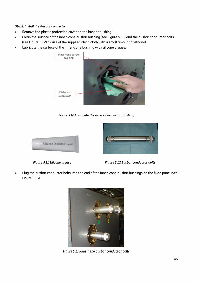
Step2: Install the Busbar connector
Remove the plastic protection cover on the busbar bushing.
Clean the surface of the inner-cone busbar bushing (see Figure 5.10) and the busbar conductor bolts
(see Figure 5.12) by use of the supplied clean cloth with a small amount of ethanol.
Lubricate the surface of the inner-cone bushing with silicone grease.
Figure 5.10 Lubricate the inner-cone busbar bushing
Figure 5.11 Silicone grease Figure 5.12 Busbar conductor bolts
Plug the busbar conductor bolts into the end of the inner-cone busbar bushings on the fixed panel (See
Figure 5.13).
Figure 5.13 Plug in the busbar conductor bolts

47
Clean the surface of the silicon rubber busbar connector by means of dielectric clean cloth dipped in
ethanol. Check and make sure there is not any defect or damage on the surface of the silicon rubber.
Lubricate the surface of the silicon rubber by proper amount of silicone grease. (See Figure 5.14).
Figure 5.14 Clean and lubricate the busbar connector
Plug the silicon rubber connector onto the busbar connector bolts (See Figure 5.15) and connect the
earthing wirings to the tank side wall screws.
Connect the earthing springs to the black semi-conductive surface of the silicone rubber busbar
connector. Connect the earthing wiring to the earthing screws of gas tank and attach.
Fit the busbar connector and connect the earthing wire to earth.
Figure 5.15 Install the busbar connector
Step3: Install the panel extension fixture
Attention: Make sure the earth wire is in the correct position to prevent pinching.

48
Assemble the rectangular tubes with hooks and the other tubes with the winch. Ensure that the fixing
brackets are on both tubes.
Figure 5.16 Ratchet Installation Tool
Install the panel ratchet installation tool near the busbar connector mounting holes on the panel side
wall. Align the fixing bracket with the mounting holes; then attach with M8 screws utilizing the existing
mounting captive nuts and holes.
Attach the Hook tubes to the unfixed panel. The winch should be installed on the fixed panel only.
Figure 5.17 Install the panel extension fixture
Adjust the ratchet winch and the hooks tubes until the distance between the wire rope and the panel
edge is 100mm. Then tighten the M5 screws to fix.

49
Figure 5.18 Tool adjustment
Step4: Mounting plate installation
When the mounting fixed panel is on the left, the next panel will be installed on the right. See mounting
plate installation below.
Remove the secondary cable brackets at the front of the fixed panel in order to insert the mounting
bracket at the bottom of the panel front. Insert the other mounting bracket at the bottom and back of
the second panel attach with M8 bolts.
When installing the panel on the right side of the fixed one, the mounting bracket installation is
opposite.
Figure 5.19 (a)Front of the panel Figure 5.19 (b) Rear of the panel
Tighten the strainer: Connect the wire rope to the hooks on the unfixed panel . Two operators must
draw up the wire rope simultaneously until the distance between two panels is around 30mm. Check

50
and adjust the parallel alignment of the two panels. Continue tightening the winch until the two panels
are connected together.
Figure 5.20 Panels connect together
Tighten the connection bolts, whilst keeping the ratchet wheel strainer in tension. Fix the bolts on the
gas tank first, and then fix all the other bolts on the panels.
Remove the winch and the mounting brackets. Move the next panel to be installed into position by
aligning with the connected panels, until the distance between them is 350~400mm. Follow the same
procedure to complete all the panel connections.
Install the secondary cable brackets after panel connections are finished.
5.6 Install Other HV Plug-in Components And Secondary
Wiring
Other HV plug-in components include: power cables, voltage transformer, surge arrester and end plugs,
etc.
Normally, the voltage transformer, surge arrester etc. have been installed on the switchgear as per the
request of the order in factory. And all the spare inner-cone bushings have been sealed with end plugs. But
they're still possible to be installed on site in the following cases:
Change of system design;
On-site testing requirements;
Engineering requirements, such as special requirements for the cable bushings.
Note:Wait 8 hours later, the silicon rubber of busbar connector will fully extended and perfectly fill
the inner cone.
Attention:
Applying high voltage tests should be at least 8 hours later, after the panel connection is finished.

51
5.6.1 HV Cable Installation
For the selection of cable terminals, please refer to the instruction of the cable supplier. The installation of
the cable terminals should be done only by trained personnel under the guide of the installation manual.
If single-cone cable is used, please follow below procedures for installing the cable terminals and HV
cables:
Remove the white plastic protective cover of the inner-cone cable bushing.
Clean the surface of the inner-cone cable bushing by means of dielectric clean cloth dipped in ethanol.
Lubricate the surface by silicone grease.
Make sure the cables and cable terminals are ready; phase sequence is correct. Install voltage
indicator sensors (if applicable).
Lead cable terminals through ring CT (If applicable).
Clean the surface of cable terminals by means of dielectric clean cloth dipped in ethanol. Lubricate the
surface by silicone grease according to the instruction manual after the alcohol has evaporates. Make
sure all the cable terminals are cleaned and lubricated.
Fit the cable terminals into the cable bushings and fasten the bolts with the torque as per Table 5/2.
Fix the cables with clamps. Fix the voltage indicator sensors and ring CT (if applicable).
Seal all the spare inner-cone cable bushings by end plugs. (Shown in Figure 5.21).
Figure 5.21 Plug-in end plugs
Applying high voltage tests should be at least 8 hours, after the cable connection is finished.
5.6.2 VT, SA and End Plug Installation
Please follow the same procedure as chapter 5.6.1 for installing voltage transformer, surge arrester and
end plugs. Applying high voltage tests should be at least 8 hours later, after these components connection
is finished.
Attention:
Take care of the cable terminals. The silicon surface of the cable terminals shall be protected against
pollution and damage (scratching etc.) during the installation!

52
Figure 5.22 Plug-in surge arrester Figure 5.23 Plug-in VT
5.6.3 Fuse Installation and Replacement of the VT Panel
1. Fuse cap location is shown as below
2. Loosen and remove the fasten bolts on the cap

53
3. Pull out the fuse cover plug with caution
4. Use the supplied screw driver to undo the fuse socket
5. Withdraw the old fuse with care
6. Empty the fuse compartment

54
7. Spray pure ethanal onto the cleaning cloth
8. Clean the inside of fuse compartment
9. Clean the new fuse (the same type as the old one)

55
10. Insert the new fuse
11. Fit and tighten the socket
12. Clean the fuse cap carefully. Check there should not be any damage or scuffing on the cap.

56
13. Apply the supplied silicon grease
14. Fit the bolt on the cap and fasten the bolts
15. It’s done

57
5.6.4 Secondary Wiring
Please refer to secondary wiring diagram to connecting the control wiring and secondary wiring for
auxiliary power supply.
VCB Control Circuit
Note:
- Must ensure electrical safety before opening the fuse compartment. It is designated a “tool-based
accessible compartment”
- If the fuse is blown up then the VT shall be checked for possible internal fault.

58
Remark:
This diagram show vacuum circuit breaker open;
C.B spring discharged; all coils are deenergized.
Symbol Description Symbol Description
Y1 Closing block magnet S1 Mechanism auxiliary switch
Y2 First opening release S2 Aux. Switch on block magnet
Y3 Closing release S3 C.B. Auxiliary switch
M0 Spring charging motor Jp R0 entry connecting line
K0 Anti-pumping relay Js K0 release connecting line
R0 Resistance
V0 ~ V4 Rectifier
3-Position Switch Control Circuit
Note:
These contacts will be reserved for three-position disconnector control dircuit.
Qx1: 15-16,17-18,19-20,21-22,27-28,29-30,49-50

59
Symbol Description Symbol Description
Qx1 Terminal block S1’, S2’, S3’, S4’ Micro switch
Qx2 Terminal block (Optional) S5’, S6’ Micro switch
Y0 Interlock coil (Optional) S7’ Micro switch
V1 Rectifier (Optional) S8’ Micro switch
M Motor S10’ Micro switch
5.7 Final Inspection
Check the outer surface of the panel is clean without any scratches on the painted surfaces. Scratches
shall be repaired, if applicable.
Fix the cover of the operating mechanism, cover of cable channel, front and rear covers.
Make sure there’s no tools left inside the switchgear.
Check the surrounding of the switchgear is in the normal condition.
5.8 Arc Duct Installation
In order to install the arc duct, follow the process mentioned below:
Pre-assembly the arc duct short channel as Figure 5.24 and long channel as Figure 5.25 by relative
parts;
Tighten all the bolts of the two channels together by using Figure 5.26 outside support plate and
Figure 5.27 inner support plate to obtain the final assembly of the arc duct channel, see Figure 5.28;
Install the assembly of the arc duct channel on side walls of the substation end panels accordingly ,
Figure 5.29;
Finally, Install the arc collecting channel (prepared by customer) on the side walls of the arc duct
channel as Figure 5.31

60
Figure 5.24 Arc duct short channel Figure 5.25 Arc duct long channel
Figure 5.26 Outside support plate Figure 5.27 Inner support plate

61
Figure 5.28 Assembly of arc duct channel
Figure 5.29 Assembly of the arc duct channel

62
Figure 5.30 Assembly of the arc collecting channel (prepared by customer)
Figure 5.31 view of the panel's final assembly

63
Figure 5.32 Bottom side view of the the panel's final assembly
From Figure 5.31 and Figure 5.32, the assembly of the arc duct makes the gas flow guides to top of it,
then leads to outside by means of arc collecting duct (prepared by customer).
Figure 5.31 Arc duct channel assembly layout drawing

64
6. Commissioning and Operation
6.1Commissioning
6.1.1Preparation
All preparation work should be done before connecting the high voltage power supply:
Connect the auxiliary power supply and check the polarity is correct.
Check the mechanical and electrical interlocking according to the schematic drawing and wiring
drawing.
Check the function of the protection device.
Check the overall condition of the system and the switchgear.
Introduce the field operator how to operate the switchgear, and hand over the installation manuals of
the switchgear, the VCB and the HV cable terminals to him.
Introduce the field operator how to handle SF6 gas on site.
Check the operation conditions of the electrical equipment connecting to the switchgear, especially
the power cables, control cables, auxiliary power supply and its polarity, remote control and earthing
conditions.
6.1.2 Initial start-up
Comply with all the relevant safety instructions.
Put all circuit breakers of the switchgear in the open position.
Put all the disconnectors in the open position.
Make sure that no panels are in the earthed position.
If there are several busbar sections or several incoming panels connecting to the same busbar section,
please check the phase sequence is correct.
Close the circuit breaker one by one to energize the feeders, and observe the monitoring device
carefully.
Check other functions by means of the high voltage power supply.
Any abnormal conditions shall be noted.
Attention:
Commissioning and operation shall be performed by trained skilled people only!

65
6.2 Switchgear Operations
6.2.1Circuit breaker
Please refer to section 3.3.
The SecoVac-G vacuum circuit breaker is equipped with motor-charging operating mechanism, able to
recharge the spring automatically.
Open and close operations are performed by the opening and closing coils. These operations shall only be
performed when the panel door is in the closed position.
If motor fault occurs, the spring can be charged manually and the open/close operation can be carried out
by pressing “O” and “I” buttons on the front of the panel.
6.2.2Three-position disconnector
Please refer to section 3.4.
The three-position disconnector is equipped with the motor-charging operating mechanism and operated
by control unit.
When operate the three-position disconnector electrically, the front door of the switchgear shall be closed
according to the interlocking.
The position of the three-position disconnector is monitored by micro switches located in the operating
mechanism.
In case of emergency, the three-position disconnector can also be operated manually.
6.3 Observation, Checking and Monitoring
6.3.1 Monitor SF6 Gas Tank
Please refer to section 3.2.
The gas tank is equipped with a gas density indicator or gas density monitor to indicate its inner pressure.
The gas density monitor is used for monitoring the gas leakage and giving out alarm signal when the gas
pressure reduced to the alarming pressure.
For monitoring the gas pressure by means of gas pressure gauge, or measuring the dew point, or perform
gas sampling and analysis, below procedures can be followed:
Remove gas density monitor through a valve on the gas tank (Note: Avoid gas leak due to removing off
the self-closing valve).
Screw the pressure gauge or dew point monitor device into the valve to observe the indication.
Remove the pressure gauge and replace it with the gas density monitor.
Note:
Every monitoring for gas pressure will cause a little gas leak. It’s necessary to control the
monitoring times to a reasonable value.

66
Sealing cover shall be used to cover the valve if the gas density monitor isn't installed for a long time.
6.3.2 Electrical/mechanical Display and Monitoring
During the operation of the switchgear, all information monitored by control unit, metering instruments
and other secondary indicators shall be observed regularly.
6.4 Test Procedures
6.4.1 Main Circuit Power-off Test
Panels are equipped with capacitive high voltage indicator system for testing the circuit condition.
User instruction of the display unit:
A functional test should be performed on the display unit immediately before and after commissioning.
The display should be clearly visible.
The light is on if operating voltage is present.
It means the panels are energized, when the light is on.
Please refer to the user manual of the specific display unit for more details.
Interface testing:
Perform interface test on all the components by means of interface tester.
Test should be performed according to local regulatory and relative IEC standard.
6.4.2 Main Circuit Phase Sequence Test
Use proper phase comparator, in combination with a capacitive voltage indicator to check the phase
sequence.
The phase comparator and the capacitive voltage detecting indicator should be of same type.
Test procedure:
Test the functionality of the phase comparator equipment, before performing phase sequence test.
Maximum measuring distance shall not exceed the length of the connecting leads.
Insert the phase comparator to corresponding phase sockets.
Always follow the instruction manual of the phase comparator.
Note:
- The indicator shall support the display unit in the switchgear, and comply with relevant standards.
- Test jack of the earth fault indicator shall not be short circuited. Only HV test for the switchgear
(such as power frequency withstand test or lightning impulse withstand test) is an exception.

67
Figure 6.1 Capacitive high voltage indicator
6.4.3 High Voltage Tests
High voltage test should be carried out with testing cables specified by switchgear manufacturer. The AC
and DC testing should be performed according to relevant standards. High voltage test shall only be
executed by certified trained person. Please consult the manufacturer for questions about the test.
Perform high voltage tests by means of proper adaptor:
Switch off the switchgear under the instruction of the safety rules and avoid re-closing.
Detect the absence of the operating voltage by inserting proper connecting lead to the testing socket
of the capacitive voltage indicator.
Remove the voltage transformer and surge arrester, cover the spare sockets with end plugs (See
Figure 6.2).
Keep the surface of the testing adapters clean and dry.
High voltage adapters (shown in Figure 6.3) are suitable for plugging in inner-cone cable bushings,
voltage transformer sockets, or busbar extension sockets. Installing voltage adapters follows the same
procedure as installing busbar connectors or cable terminals.
Before installing the testing adapter, an earth wire should be connected to the terminal of the testing
adapter. Remove this earth wire before applying testing voltage.
Clean the testing socket and insert the testing adapter.
Make sure the testing adapter has enough insulating distance between phases and phase to earth.
Make sure all the warnings/notices are followed.
Perform the high voltage tests as per specific requirements.
After all the tests are finished, remove the adapters and return the switchgear into the original status.
Figure 6.2 Cover the spare sockets Figure6.3 Perform HV test by voltage adapter

68
Before test, please make sure that:
All the switchgear panels are power off;
Proper measures are performed on the panels to avoid re-closing;
Power-off condition has been checked;
Inductive voltage caused by secondary winding of the VT is excluded;
Short circuit the testing sockets of the voltage indicator;
When doing cable testing, if the switchgear is in the earthed position, open the circuit breaker to
isolate the earthed condition.
6.4.4 Current Test
Current test can be performed by current testing adapter (Shown in Figure 3.23) as follows:
Test functions of the control and protection unit by injecting current to the primary circuit.
Earthing for maintenance by means of short-circuit the main busbars through the special earthing
device.
6.5 Safety Instructions For Voltage Transformer Operation
Secondary wiring and its earthing shall be connected according to the schematic drawings. It’s dangerous
to loose the earthing bolts on the “N” terminal during the operation of the voltage transformer.
Only at the moment of disconnecting the voltage transformer from the main circuit for testing purpose,
can the earthing bolts on the “N” terminal be loosened.
Only use the original earthing bolts.
Note:
Disconnect the opening coil and latch the trip signal of the testing equipment during
test, to avoid damaging the opening coil.

69
7. Maintenance, Repair and Recycling
7.1 General
According to GB3906, DL/T404 and IEC 62271-200 standards, inspection and maintenance shall be
provided to keep the switchgear in proper function and achieve a maximum lifetime. The recommend
inspection and maintenance interval depends on the operating frequencies, short-circuit fault breaking
cycles of the switchgear and its surroundings including humidity, pollution, corrosive vapour etc.
All the high voltage components of SecoCube are completely sealed in the gas tank filled with insulating
gas, consequently not influenced by the environment. Therefore, all the high voltage components are
maintenance free under normal conditions.
Maintenance for the control compartment and its inside components depends on the ambient environment,
such as humidity, pollution and corrosive vapour.
Maintenance shall be performed according to this instruction manual, as well as relevant safety
regulations.
7.2 Inspection And Maintenance
Under normal operating conditions, the mechanism shall be inspected by trained skilled person after 10
years operation or every5,000 operating cycles of the circuit breaker or every 1,000 operating cycles of the
three-position disconnector. Such inspection also includes functional checking of protection and control
units as well as the interlocks.
In special operating conditions (such as pollution and erosion conditions), the maintenance cycle shall be
shortened accordingly. The maintenance work will include the following items but not limited to:
Appearance inspection, incl. checking the pollution, erosion and humidity conditions.
Electrical and mechanical inspection for the switchgear and controlgear.
The following items shall be followed if cleaning is required:
According to the instruction manual and related safety regulations, necessary isolating and safety
measures shall be taken for the cleaning areas.
Clean the dust on the surface with dry and soft cloth.
Cable cleanser can be used to clean the silicon rubber part of cable plug and busbar bushing etc.
In any case, the semi-conductor part of the silicon rubber and its surfacing shall not be broken.
After cleaned, the equipment shall be dried before put into operation.
7.2.1 Vacuum Circuit Breaker
The embedded poles of SecoVac-G vacuum circuit breaker are maintenance free. However, the
transmission parts of the operating mechanism shall be inspected every 10 years or every 5,000 operating
cycles. Check the lubricant situation, and then re-lubricate them.

70
7.2.2 Three-position Disconnector
The three-position disconnector is maintenance free within its mechanical lifetime of 1,000 operating
cycles. However, customer can perform regular inspection for the motor driven mechanism, such as
function check and appearance inspection. The lubricating of the mechanism at accessible bearing points
shall be checked every 10 years.
Figure 7.1 The chain and gear etc. of the mechanism shall be lubricated
Note: after every 10 year or correspond operation times should be check the situation of transmission part
and lubricate.
7.2.3 Insulating Gas And Its Maintenance
The SecoCube gas tank is a gas-tight system, which is fully sealed within its lifetime. It is not necessary to
re-fill the gas tank during the expected service life of SecoCube switchgear. Therefore, the insulating gas is
maintenance free under normal operating conditions and it’s not necessary to check the gas quality.
However, as per specific requirement of customer, it may become necessary to check the pressure of the
insulation gas as part of the regular inspection activities. For details, please refer to section 6.3.1.
If the gas pressure is lower than 0.11 MPa(abs.), re-gas should be performed by trained service engineer
and the reason for the gas leak shall be detected. Please consult local service organization of the
switchgear manufacturer for details.
7.3 Instruction for dispatching the gas and refilling the gas
Inspect the pressure gauge or density monitor to check if it is in the normal green area, or if there is any
alarm signals send out. If normal, it means the panel is running in good condition and no need to refill the
gas. Record the pressure data each time when doing inspection.
If the gas pressure gauge is found out of the green area, the density monitor alarm might have sent the
signals already. And it should be informed to the service personnel or the manufacturers as soon as
possible to find out the real reasons. Or the panel should be refilled the gas on site accordingly as following
steps:
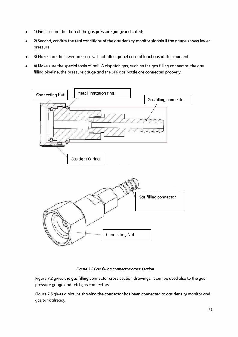
71
1) First, record the data of the gas pressure gauge indicated;
2) Second, confirm the real conditions of the gas density monitor signals if the gauge shows lower
pressure;
3) Make sure the lower pressure will not affect panel normal functions at this moment;
4) Make sure the special tools of refill & dispatch gas, such as the gas filling connector, the gas
filling pipeline, the pressure gauge and the SF6 gas bottle are connected properly;
Figure 7.2 Gas filling connector cross section
Figure 7.2 gives the gas filling connector cross section drawings. It can be used also to the gas
pressure gauge and refill gas connectors.
Figure 7.3 gives a picture showing the connector has been connected to gas density monitor and
gas tank already.
Gas tight O-ring
Metal limitation ring Connecting Nut
Gas filling connector
Gas filling connector
Connecting Nut

72
Figure7.3 Gas density monitor with density indicator assembly
5) Remove the metal limitation ring from gas pressure gauge.
6) Turn the connecting nut counterclockwise by means of special tools as Figure 7.4 showing to
disassembly the pressure gauge.
Figure 7.4 Special tools for dismantle the pressure gauge
7) Open the valve of SF6 bottle slightly to despatch the remained air in the pipeline of gas filling
system.
8) Joint the connecting nut towards the self-tight valve of the gas tank as quickly as possible by
means of pushing it inwards, then tighten the connecting nut clockwise to fix the gas connector to
the gas tank. See Figure 7.5 and Figure 7.6.
Attention:
To remove the connecting nut, catch the pressure gauges slightly and make sure the pressure gauge
doesn’t rotate with connecting nut together to protect the gas filling connector and gas tight O-rings
from damage.

73
Figure 7.5 Tools for dismantle the pressure gauge
Figure 7.6 Gas connector assembly to gas tank
Connecting
Nut Gas pipe
connector
Metal limitation
ring connector
Self-tight valve

74
9) Open the SF6 gas bottle valve to fill the gas to tank and observe the pressure gauge level
carefully until it arrives the prospect pressure 0.02-0.03MPa (rel.). Close the SF6 gas bottle valve
tightly. See Figure 7.7 and 7.8.
Figure 7.7 SF6 gas bottle and pressure gauge Figure 7.8 Connection of SF6 gas bottle
10) Repeat the step 6) to disassembly the connecting nut of gas filling connector from gas tank.
11) Repeat the step 8) with a pressure gauge to assembly it into the gas tank again. If the gauge
shows in green area, then assembly the metal limitation ring back to its right position. Record the
pressure gauge level accordingly afterwards.
12) Apply the leakage detecting system to the panel to check if any leakage happens or not. If no,
increase the pressure gauge inspection times for certain period carefully.
7.4 Maintenance and Components Replacement
Normally, all high voltage parts and the gas tanks are maintenance free during its life time. However
special service conditions or special circumstances may require maintenance work.

75
Customers can carry out repair works on panel enclosure themselves, while the stainless steel gas tanks,
VCB mechanisms and 3-position disconnectors should be maintained by certified trained people. Please
consult local service organization of the switchgear manufacturer for details.
7.5 Spare Parts and Auxiliary Materials
Spare parts and auxiliary materials for service and maintenance like nitrogen gas, SF6, drying desiccant
bags, lubricant, silicon grease, dielectric clean cloth and paint may be needed. Please contact the
manufacturer for specification and delivery of these materials.
7.6 Recycling Regulations
When SecoCube reaches the end of its service life, recycling for the products shall be done under the
compliance of relative standards in order to protect the environment.
If customer wants recycling service, please consult the manufacturer for more information.

76
8. Notice
8.1 Gas system
The mixture of nitrogen and 𝑆𝐹6 inside the gas tank is for insulation only, while the arc making and
breaking is achieved by vacuum circuit breaker. In normal operating conditions, as the insulating gas is
free from decomposing, aging and contamination, it is maintenance free in its service life.
Whenever the internal arc fault occurs, most of the decomposed insulating gas under high temperature
will recompose and recover under low temperature while the remaining of it will be absorbed by the
desiccant.
Both nitrogen and 𝑆𝐹6 in pure form are colorless and odorless gases, which cannot be recognized by sight
or smell. Since the density of nitrogen is lower than that of air, it won't be accumulated at ventilated or
low-lying place, but high density of nitrogen will have the suffocation risk in air-tight rooms. While due to
higher density of 𝑆𝐹6 compared to air, it will be accumulated at low-lying place and will also have
suffocation risk in air-tight rooms.
Due to the fact that nitrogen is the majority ingredient of air, the gas insulation by nitrogen eliminates the
effect of aging and erosion from oxygen and moisture to the electrical equipment.
It shall be noted that the decomposition of SF6 under arcing, results in a gas that is extremely poisonous. In
case the decomposition occurs in low density, it has a color with pungent smell and causalgia that is
harmful for the human nose, mouth and eyes. Gas mask shall be worn to avoid direct contact of the
resulting gas with the skin while accessing during fault.
The decomposition of nitrogen under arcing is not poisonous and can be emitted to the atmosphere
directly. But the effect on the decomposition of other insulating parts under arcing shall be considered.
In normal conditions, the insulating gas shall not suffer arcing, and the nitrogen can be emitted to the
atmosphere directly. But for the mixture of nitrogen and SF6, since the greenhouse effect of SF6 is 23900
times more than that of CO2, and will remain up to 3200 years after its emission to the atmosphere, SF6 will
cause extreme harm to the environment after its long-term accumulation and hence, it shall be recycled
instead of being emitted to the atmosphere directly.
When nitrogen is used as the insulating gas, the air content doesn't need to be regulated in principle. But it
has to be noted that the oxygen in the air will affect the aging inside the gas tank, while the moisture will
affect the dew point and the insulation level under low temperature.
If need to handle insulating gas on site, please contact GE.
8.2 Connection of HV Plug-in Components
“Plug-in” technology is widely used in assembling and testing SecoCube switchgear, such as busbar
connection, cable connection, VT connection, surge arrester connection and test adapter connection etc.
The connection quality will impact the performance of the equipment on site.
Plug-in connection is a way to realize interface insulation by connecting two insulating interfaces together
with certain pressure. Thanks to the tightly joint and the insulating grease, the insulation level will not be
impacted by ambient environment.

77
The pressure for connecting two insulating interfaces is achieved by the tightening bolts on the plug-in
components. Proper assembling dimensions and tightening torques should be ensured.
There may be some residual air between the insulating interfaces after connection is done. In order to emit
the residual air and maintain the insulation level, panels should be placed more than 8 hours before
performing high voltage tests on them.
8.3 About Interlocking
SecoCube is equipped with reliable electrical and mechanical interlocking to avoid misoperation. The
interlocks may change as per requirements of the users or the system design. Please pay attention to the
changes during operation, especially on manual operation.
Force to operate the switchgear is not allowed in manual operation, in order to avoid damage the
interlocks and the mechanism.
Please follow the instruction in delivered documents. Any question about it, please contact the
manufacturer.

Printing Code: IN201501B13EN
© Copyright GE Industrial Solutions 2015
Approval Number: GECUBE36201501
Japan11F, Akasaka Park Bldg.,5-2-20, Akasaka, Minato-kuTokyo 107-6111T : +81 3 3588 5288F : +81 3 3585 3010
North AsiaKorea22, Daewangpangyo-ro 712 beon-gil, Bundang-gu, Seongnam-si, Gyeonggi-do, 463-400, KoreaT: +82-31-620-6000F: +82-31-620-7070
572 Swan Street, Building 2, Richmond, VIC 3121T: 1800 733 632
Australia & New Zealand
IndiaPlot No. 42/1 & 45/14, Electronic City-Phase IIBangalore-560100T: (080) 41434000F: (080) 41434199
India
Shanghai4F, Building 2, CTP, No.1 Hua Tuo Rd. Zhang Jiang Hi-Tech Park, Shanghai, China 201203T : +86 21 3877 7888F : +86 21 3877 7600
Taiwan6F, No. 8, Min Sheng E. Rd., Sec. 3, Taipei 10480T : +886 2 2183 7000F : +886 2 2516 6829
Greater China
Spain & PortugalMiño 122, naves E - F08223 - Terrassa - BarcelonaT: +34 93 736 57 00
BelgiumNieuwevaart 51, B-9000 GentT: +32 (0)9 265 21 11
FinlandKuortaneenkatu 2, FI-00510 HelsinkiT: +358 (0)10 394 3760
FranceParis Nord 2, 13, rue de la PerdrixF-95958 Roissy CDG CédexT: +33 (0)800 912 816
PolandUl. Odrowaza 15, 03-310 WarszawaT: +48 22 519 76 00andUl. Leszczyńska 6, Bielsko-Biała 43-300T: +48 33 828 62 33
Europe & Middle EastItalyCentro Direzionale ColleoniVia Paracelso 16, Palazzo Andromeda B1 I-20864 Agrate Brianza (MB)T: +39 039 637 3701
NetherlandsParallelweg 10, Nl-7482 CA HaaksbergenT: +31 (0)53 573 03 03
GermanyRobert-Bosch Str. 2a, 50354 Hürth-EfferenT: +49 (0) 2233/ 9719-0
United Arab EmiratesInjaz Building, 3rd FloorDubai Internet City, PO Box 11549, DubaiT: +971 4 4546912
HungaryVaci ut 81-83. H-1139 BudapestT: +36 1 447 6050
Russia27/8, Electrozavodskaya street, Moscow, 107023T: +7 495 937 11 11
South AfricaUnit 4, 130 Gazelle Avenue, Corporate Park Midrand 1685P.O. Box 76672 Wendywood 2144T: +27 11 238 3000
United Kingdom2 The Arena, Downshire WayBracknell, Berkshire RG12 1PUT: +44 (0) 800 587 1239
TurkeyWindowist Tower Eski Büyükdere Cad. No: 26 Kat: 5Maslak 34467, Sarıyer, İstanbulT: +90 212 214 76 91F: +90 212 214 77 30
Latin America Headquarters790 N.W. 107th Avenue, Suite 200, Miami, Fl 33172 USAT: +1 305 551 5155
ChileVespucio Norte, Avenida Presidente Eduardo FreiMontalva 6001, Edificio N° 66Comuna: Conchalí, Sector el Cortijo, SantiagoT: (56 2) 928-4700
Latin AmericaBrazilAv. María Coelho Aguiar, 215, Bloco C - 6.AndarJd.São Luiz, 05804-900, São PauloT: +55 11 36141900
MexicoAv. Churubusco 3900 Nte, Col. Industrial Benito JuárezMonterrey, N.L. 64517T: (01-800) 800-1968
USA41 Woodford Avenue, Plainville CT, USA 06062and 12305 Kurland Drive, Houston, TX USA 77034T: +1 800-431-7867
2000 Centre Green Way Suite 200 Cary, NC 27513T: +1 919-238-6620
Canada2300 Meadowvale Blvd. Mississauga, ON L5N 5P9T: 1-800-GE1-STOP
North America
IndonesiaBRI II Tower, 27th floor, Jl. Jend. Sudirman No. 44-46Jakarta 10210T: +62 21 573 0430F: +62 21 574 7089
SingaporeLevel 9, The Metropolis Tower 211 North Buona Vista Drive, Singapore 138589T : +65 6220 7022
Philippines & Guam8F Net Cube Building, 30th Street, Corner 3rd Avenue, Crescent West Park, Global City Taguig 1634T : +63 2 877 7000F : +63 2 846 0629
Vietnam, Cambodia & LaosFloors 6 & 7 - The Crescent CR3, 111 Ton Dat Tien Street,Tan Phu Ward, District 7, Ho Chi Minh City 710000T : + 84 8 54137000F : + 84 8 54137040
South East AsiaMalaysiaLevel 6, 1 Sentral, Jalan Rakyat,Kuala Lumpur 50470T : +603 2273 9788F : +603 2273 3481
Thailand & Myanmar7th floor, Capital Tower, All Seasons Place, 87/1 Wireless Road, Lumpini, Pathumwan, Bangkok 10330T : +66 2 648 0199F : +66 2 648 0100
For more information, please visitwww.geindustrial.com