aac wall panel chad technical - chad · pdf fileaac wall panel chad technical manual plaster...
TRANSCRIPT

CHAD PLASTER AND FACADES
AAC WALL PANEL
TECHNICAL MANUAL
CHADPLASTER & FACADES
R E TA I L & C O N T R A C T I N G
BUILDING BETTER AND SMARTER

AAC WALL PANELTECHNICAL MANUALCHAD
PLASTER & FACADES
R E TA I L & C O N T R A C T I N G
CHAD PLASTER AND FACADES
Page 2June 2013
Building better and smarter starts with Eco Panel. Chad Plaster and Facades Aerated Auto-claved Concrete (AAC) Eco Panel provides ultra-high integrated insulation and facilitates building a home quicker. Being clad much faster than conventional bricks, the speed of construction reaches key stages quickly. Eco Panel is as solid and as durable as traditional masonry, yet its lightweight properties get any project to “Lockup” quicker. Eco Panel adds to a safer and cleaner worksite with less “cleanup” at the conclusion of the project. In compari-son to traditional rendered masonry products, Eco Panel saves time and money. The inher-ent Thermal Mass and Thermal Resistance properties of Eco Panel showcases its energy e�ciency properties. Eco Panel also brings to the total package further bene�ts of high �re resistance. Eco Panel does not combust in the event of �re and will not omit toxic gases. It provides a Load Bearing FRL of 240/180/60 and a non-load bearing FRL of 240/240/240. Eco Panel also has sound acoustic reducing qualities equivalent and better than traditional masonry products.
AAC Eco Panel is an environmentally friendly product. It is pollution free, emits no harmful emissions and has an excellent environmental performance. Based on ISO14025, it has been awarded the environmental declaration. It has fantastic design �exibility and it’s aesthetic appeal gives designers the range and �exibility of using a masonry product where previously non-masonry products could be used.

AAC WALL PANELTECHNICAL MANUALCHAD
PLASTER & FACADES
R E TA I L & C O N T R A C T I N G
CHAD PLASTER AND FACADES
Page 3June 2013
IntroductionECO Panel (AAC) is manufactured via a combination of lime and/or cement, combined with �nely divided sand and other �ller materials. This mix is poured into a mould, an expanding agent reacts with the other elements, and the mix begins to rise in the mould while the reaction with the expanding agent creates �nely dispersed air bubbles. This is cured under high pressure and temperature to provide a relatively strong, lightweight cellular structure, incorporating small uniformly distributed bubbles.
After the semi solid material is pre-cured, the block out of the mould is cut and sliced into the required sizes. Once appropriately sized, the panels are steam pressure cured in auto-clave ovens. This manufacturing process is central to what gives AAC panel its excellent thermal insulation �re resistance protection and acoustic absorption qualities.
SAND BALL MILL MIX
CEMENT LIME
WATER
THE AAC MANUFACTURING PROCESS
WIRE REINFORCEMENT
ASSEMBLING
CAST EXPANSION CUTTING MACHINE
AUTOCLAVE
PACKAGED FOR DELIVERY AAC PRODUCT
CORROSION PROTECTIONTREATMENT
EXPANDING AGENT

AAC WALL PANELTECHNICAL MANUALCHAD
PLASTER & FACADES
R E TA I L & C O N T R A C T I N G
CHAD PLASTER AND FACADES
Page 4June 2013
The ECO PANEL (AAC) system is an innovative Autoclaved Aerated Concrete light-weight cement-based material, incorporating small uniformly distributed bubbles that result in its unique properties of lightness, high thermal resistance, workability and strength. ECO PANEL (AAC) is available as reinforced AAC wall or �oor panels.
This manual is available in hardcopy, softcopy or electronic form and is intended for use by quali�ed and experienced architects, engineers and builders. The authors, publishers and distributors of this manual, sample speci�cation and the associated drawings do not accept any responsibility for incorrect, inappropriate or incomplete use of this information. It is the express intention that designers will edit them to suit the particular requirements of speci�c construction projects.
This manual has been prepared in the context of the National Construction Code of Australia. Architects, engineers and builders should make themselves aware of any recent changes to these documents, to any Standards referred to therein, or to local variations or requirements. The authors, publishers and distributors of this speci�cation and the associated drawings do not accept any responsibility for failure to do so.
There are many factors to be considered when designing building solutions from Eco Panel Autoclaved Aerated Concrete (AAC) panels, and CHAD Plaster and Facades provides design tables and charts to assist the designer. The Eco Panels are grouped into two basic types relating to application. These types being:-
Floor panels; Wall panels;
ECO Panel Aerated Autoclaved Concrete (AAC)

AAC WALL PANELTECHNICAL MANUALCHAD
PLASTER & FACADES
R E TA I L & C O N T R A C T I N G
CHAD PLASTER AND FACADES
Page 5June 2013
Applications
AAC Panels are reinforced, and are designed for �oors and walls in multi-residential, commercial, residential (domestic) and industrial construction.
MULTI-RESIDENTIAL CONSTRUCTION Non-loadbearing external wall panels, generally panels are �xed to a reinforced concrete structural frame. Internal wall panels – party walls / risers / shaft walls.
COMMERCIAL CONSTRUCTION Non-loadbearing external wall panels.
RESIDENTIAL (DOMESTIC) CONSTRUCTION External cladding for loadbearing wall panels, limited to 2 storey construction; Roof panels; Floor panels
INDUSTRIAL CONSTRUCTION Non-loadbearing wall panels, larger panels spanning vertically can be successfully incorporated into industrial wall applications. Mezzanine �oors Ceiling panels – �re exits.

AAC WALL PANELTECHNICAL MANUALCHAD
PLASTER & FACADES
R E TA I L & C O N T R A C T I N G
CHAD PLASTER AND FACADES
Page 6June 2013
CODES AND REGULATIONS
Design procedures for the veri�cation of members and structures consisting of AAC panels generally follow the design principles outlined in Australian Standard AS3600-2009 – Concrete Structures, with the exception of cover requirements for durability and development length for reinforcement.
The loadings on the panel products are to be determined in accordance with the Australian Standard AS1170 “Design Actions” series of codes. These codes cover typical loadings, such as dead load, live load, wind load, earthquake load, as well as others.
GUARANTEE AND CERTIFICATION
CHAD Plaster and Facades is a supplier of AAC products. CHAD Plaster and Facades guarantee the products and the products used in the systems described in CHAD Plaster and Facades literature, subject to the terms and conditions of the CHAD Plaster and Facades Guarantee. We do not however guarantee the components, products or services, such as installation and specialist advice, supplied by others.
CHAD Plaster and Facades conducts appropriate testing of its products and systems, and sources opinions to determine performance levels. These include structural, �re and acoustic. CHAD Plaster and Facades can provide copies of test results and opinions presenting the performance characteristics of its products and systems.
When using Eco Panel systems in speci�c projects, CHAD Plaster and Facades suggest special-ists be consulted to ensure compliance with the National Construction Code of Australia and relevant Australian Standards. CHAD Plaster and Facades can provide a certi�cation for its panel products. For a speci�c project, an appropriate specialist can provide the certi�cation for the relevant performance criteria of the systems and supporting structure.
Design Actions

AAC WALL PANELTECHNICAL MANUALCHAD
PLASTER & FACADES
R E TA I L & C O N T R A C T I N G
CHAD PLASTER AND FACADES
Page 7June 2013
Summary of Properties of the PANEL AAC Products
Application Wall Panels Wall Panels Floor Panels 75mm 100mm 75mm Panel thickness, T, mm 75 100 75
Panel width, W, mm 600 450 600
Panel length, L, mm Varies Varies 1,800
Wet density kg/m3 (wout reo weight) 720 - 820 720 - 820 720 - 820
Oven-dry density, kg/m3 520 - 620 520 - 620 520 – 620
compressive strength average Mpa 5.0 5.0 5.0
Number of layers of Reinforcement 1 2 1
Main reinforcement diameter, mm 5 5 5
No of reinforcement strands 5 3 5
Reinforcement centres 37/37 18/64/18 37/37
Characteristic uncond compressive strength fck MPA 1.1 1.1 1.1
Characteristic oven dry compressive strength fck MPA 1.9 1.9 1.9
Mean elastic modulus E Mpa 1800 1800 1800
Capacity Kpa
Simple Spans lm
Wall Panels Wall Panels 75mm 100mm 0.9 3.56 15.71
1.2 2 8.84
1.5 1.28 5.66
1.8 0.89 3.93
2.1 0.65 2.89
2.4 0.5 2.21
2.7 1.75
3 1.41
3.3 1.17

AAC WALL PANELTECHNICAL MANUALCHAD
PLASTER & FACADES
R E TA I L & C O N T R A C T I N G
CHAD PLASTER AND FACADES
Page 8June 2013
ECO AAC Steel Reinforced Autoclaved Aerated PanelsECO Panels AAC Steel Reinforced Autoclaved Aerated Panels have the following properties:Characteristic compressive strength, fck = 5.0 MPaCharacteristic �exural strength, � = 1.0 MPaCharacteristic elastic modulus, E = 1,800 MPa
Panel thickness, T = 75 mmPanel width, B = 600 mmPanel lengths (standard sizes), L = 2,400 mm, 2,550 mm, 2,700 mm, 2,850 mm, 3,000mm
Reinforcement yield strength, fsk = 235 MPaReinforcement diameter, R = 5mmNumber of reinforcing strands, N = 5 (over a 600 mm width)Ns = 8 (0ver 2,700 to 3,000 mm panel length)Depth of Reinforcement, d = 45 mm (30 mm from opposite face)Moment capacity (medium reinforcement, 0.286 < s < 0.375), Φ Mu = 0.685 kN.m
Using this data, the ultimate bending capacities (expressed in terms of uniform pressure) for various spans of ECO Panels AAC Steel Reinforced Autoclaved Aerated Panels are identi�ed in the following table.
75 mm ECO Reinforced AAC Panels

AAC WALL PANELTECHNICAL MANUALCHAD
PLASTER & FACADES
R E TA I L & C O N T R A C T I N G
CHAD PLASTER AND FACADES
Page 9June 2013
75 mm ECOL-MEGA PANEL (AAC) Steel Reinforced Autoclaved Aerated Wall Panels with reinforcement in centre

AAC WALL PANELTECHNICAL MANUALCHAD
PLASTER & FACADES
R E TA I L & C O N T R A C T I N G
CHAD PLASTER AND FACADES
Page 10June 2013
100 mm ECOL-MEGA PANEL (AAC) Steel Reinforced Autoclaved Aerated Wall Panels

AAC WALL PANELTECHNICAL MANUALCHAD
PLASTER & FACADES
R E TA I L & C O N T R A C T I N G
CHAD PLASTER AND FACADES
75 mm ECOL-MEGA PANEL (AAC) Steel ReinforcedAutoclave Aerated Floor Panels
Page 11June 2013
Spanning joists at 450 mm centres, are suitable for the support of 3.0 kPa distributed or a 1.8 kN point load over an area of 350 mm2 (located at least 100 mm from the panel edge). This corresponds to balcony loads for domestic housing.
Spanning joists at 600 mm centres, are suitable for the support of 1.5 kPa distributed or a 1.8 kN point load over an area of 350 mm2 (located at least 100 mm from the panel edge). This corresponds to the internal loads for domestic housing.
The speci�er and builder must ensure that there is provision to prevent and/or control cracking of any brittle �oor coverings, such as tiles, particularly at 600 mm joist spacing. In the case of 600 mm joist spacing, ductile surfaces are more appropiate.

AAC WALL PANELTECHNICAL MANUALCHAD
PLASTER & FACADES
R E TA I L & C O N T R A C T I N G
CHAD PLASTER AND FACADES
Page 12June 2013
Structural Design Procedure
This section covers the structural design of ECO PANEL (AAC) for compliance with the structural requirements of the National Construction Code of Australia.
DESIGN AND CONSTRUCTION STANDARDS
The National Construction Code of Australia provides the overall regulatory framework for the design and construction of buildings in Australia.
Eco Panels AAC, provided as steel reinforced autoclaved aerated panels, are designed in accordance with the recommendations of “RILEM Recommended Practice – Autoclaved Aerated Concrete – Properties, Testing and Design”. Because this system is outside the scope of the most relevant National Construction Code of Australia referenced document, AS3700, its use must be treated, under the National Construction Code of Australia, as an Alternative Solution in a deemed to satisfy capacity.
Eco Panels AAC, provided as autoclaved aerated blocks set in thin-bed adhesive, are designed in accordance with AS 3700-2001 Masonry Structures.
LOADS
Eco Panels AAC walls should be designed to withstand the loads set out in the National Construction Code of Australia and Standards, as listed below:
AS/NZS 1170.0 Structural design actions Part 0: General principles AS/NZS 1170.1 Structural design actions Part 1: Permanent, imposed and other actions AS/NZS 1170.2 Structural design actions Part 2: Wind actions AS/NZS 1170.3 Structural design actions Part 3: Snow and ice actions AS 1170.4 Structural design actions Part 4: Earthquake actions in Australia AS 4055 Wind loads for housing

AAC WALL PANELTECHNICAL MANUALCHAD
PLASTER & FACADES
R E TA I L & C O N T R A C T I N G
CHAD PLASTER AND FACADES
Page 13June 2013
Design of AAC ECO Panels for Robustness AS3700 Clause 4.6 requires that panels must be designed for robustness. The robustness coe�cient provides practical limits to slenderness for walls and piers and this must be taken into consideration in addition to all other design requirements.
With the requirement to design for loads in the Standards, it is possible for the lateral loads on some walls to be neglected. For example, internal loadbearing basement walls of an apartment building may not be required to be designed for wind, �re or earthquake. However, it is possible for all three loads, as well as vehicle impact, to impinge on such basement walls. The robustness provisions are a practical means of providing an upper limit on the dimensions of walls and isolated piers, thus ensuring that unreasonably large spans are not speci�ed. They are not a substitute for rational design for calculated loads, but rather a global limit beyond which even the most lightly loaded walls and piers should not be built. The robustness provisions must not be used to justify structures which would otherwise fail to meet the design for the calculated loads. Close consideration must be given to chasing and consequent reduction in support. The robustness coe�cients of AS3700 Table 4.2 (see below) are applicable to Unreinforced Eco Blocks (AAC) Blocks in thin-bed adhesive. In this manual, the robustness criteria are also applied to Reinforced Eco Panels AAC, which are outside the scope of AS 3700, to maintain consistency. The horizontal robustness coe�cient is not applicable to Reinforced AAC Panels, which span in one direction only.
CAPACITY REDUCTION FACTORSCapacity reduction factors given in AS3700 Table 4.1 are used in this manual.
RESISTANCE TO UNIFORM COMPRESSIONThe method based on AS3700 Clause 7.3 has also been used for Reinforced NALC AAC. RILEM Recommended Practice – AAC – Properties, Testing and Design only provides a method for Unreinforced AAC.

AAC WALL PANELTECHNICAL MANUALCHAD
PLASTER & FACADES
R E TA I L & C O N T R A C T I N G
CHAD PLASTER AND FACADES
Page 14June 2013
Fire Design
Autoclaved Aerated Concrete (AAC) is one of the most e�ective building materials for providing a barrier to �re. AAC has shown itself to be non-combustible and very stable under �re loading, resulting in structural systems that have high �re resistance level (FRL) ratings. The properties that highlight the high level performance of AAC under �re loading are following:-
NATIONAL CONSTRUCTION CODE OF AUSTRALIA AND AUSTRALIAN STANDARDS
The NCC Volume 1 Part C de�nes the �re resistance requirements for Class 2 to 9 buildings. The NCC Volume 2 Part 3.7.1 de�nes the �re resistance requirements for Class 1 and 10a buildings. Various Australian Standards, including AS 3700 set out the means of determining the �re resistance of masonry, including AAC, for the three limit states described in the NCC. It requires designers to check three separate �re performance limit states: Structural adequacy (resistance to collapse) Integrity (resistance to cracking) Insulation (resistance to the passage of heat).
FIRE DESIGN AND FIRE RESISTANCE LEVEL (FRL) RATINGS
The National Construction Code of Australia regulations express the �re performance of a wall with the rating system called the ‘Fire Resistance Level’ (FRL). The FRL ratings in the CHAD Plaster and Facades Technical Manual have been determined by testing in accordance with AS1530.4 – Fire Resisting Tests of Elements of Building Construction – EXOVA.
The �re FRL rating consists of three performance criteria: a) resistance to collapse b) resistance to cracking c) resistance to the passage of heat
For non-load bearing walls, there is no requirement to express the ‘structural adequacy’ criteria.
FIRE CERTIFICATE AND REPORTS
Copies of the test reports for �re testing performed on the CHAD Plaster and Facades blocks are available by contacting CHAD Plaster and Facades.
ADDITIONAL DESIGN CONSIDERATIONS
Fire-rated block walls should comply with both strength and robustness requirements and minimum slenderness ratios outlined in AS3700 – Masonry Structures code.

AAC WALL PANELTECHNICAL MANUALCHAD
PLASTER & FACADES
R E TA I L & C O N T R A C T I N G
CHAD PLASTER AND FACADES
Page 15June 2013
Fire Tests

AAC WALL PANELTECHNICAL MANUALCHAD
PLASTER & FACADES
R E TA I L & C O N T R A C T I N G
CHAD PLASTER AND FACADES
Page 16June 2013
75mm AAC ECO Panel Wall Panels After 4 hours at 1200 Degrees with Vertical Loading
AAC WALL PANELTECHNICAL MANUALCHAD
PLASTER & FACADES
R E TA I L & C O N T R A C T I N G
CHAD PLASTER AND FACADES
Page 17June 2013
Acoustic Design
SOUND
Sound will have two basic characteristics – amplitude and frequency (or pitch) of the sound. The amplitude of the sound is a measure of the magnitude of the oscillation. The frequency of the sound is a measure of how quickly the vibrating surface is moving back and forth.
ACOUSTIC MATERIALS – SOUND BARRIERS AND SOUND ABSORBERS
There are materials that absorb sound and prevent it re�ecting around a room for example, echo. These materials are sound absorbers and are usually soft to touch for example Glasswool insulation, carpets, curtains and mineral �bres.
The second categories of materials are those that reduce transmission of sound through the material from one room to another. These materials are referred to as sound barriers for example Eco Panel Wall and Floor Panels.
Both types of materials are necessary for providing a satisfactory acoustic environment in a building.
The careful combination of acoustic barriers and sound absorbent materials can provide a very cost e�ective and space e�cient solution.
STC & RW ACOUSTIC RATING SYSTEMS
The National Construction Code of Australia (NCC) presents the Performance Requirements for sound insulation ratings. The sound insulation ratings set minimum values to consider for two types of sound: airborne sound and impact generated sound.
The Rw rating curve (similar to the STC curve) was basically derived from sound insulation requirements for speech. Modern living with its use of large television sets, home entertainment units for music and the home cinema with its surround sound had increased the requirement for low frequency sound insulation. In this regard, the Rw spectrum is inadequate. The ISO rating system has a correction factor for tra�c noise for external walls, roofs and windows. This correction factor Ctr when applied to the Rw curve also provides better relationship of sound insulation for the low frequencies of the various home entertainment systems. The term Rw + Ctr has been adopted in the Australian NCC and the Association of Australian Acoustical Consultants Star Rating System for Apartments and Townhouses.

AAC WALL PANELTECHNICAL MANUALCHAD
PLASTER & FACADES
R E TA I L & C O N T R A C T I N G
CHAD PLASTER AND FACADES
Page 18June 2013
NCC VOLUME 1 CLAUSE F5.5 REQUIREMENTS
NCC Vol 1 Clause F5.5 Requirements
Walls that separate sole occu-pancy units in a Class 2 or 3 building or between two Class 1 buildings
Rw + Ctr (airborne) not less than 50,
Impact sound resistance, if the wall separates a habitable room in one sole occupancy unit from a bathroom, sanitary compart-ment, laundry or kitchen of another unit or plant room or lift shaft).
Walls that separate a sole occupancy unit from a plant room, lift shaft, stairway, public corridor, public lobby or the like in a Class 2 or 3 building
Rw (airborne) not less than 50
Impact sound resistance, if the wall separates a habitable room in one sole occupancy unit from a plant room, or lift shaft
Walls that separate two sole occupancy units or separates a sole occupancy unit from a kitchen, bathroom, sanitary compartment (not en-suite), laundry, plant room or utilities room in a Class 9c aged-care building
Rw (airborne) not less than 45,
Impact sound resistance if the wall separates a habitable room in one sole occupancy unit from a kitchen or laundry.
A door incorporated in a wall that separates a sole occupancy unit from stairway, public corri-dor, public lobby or the like in Class 2 or 3 building and a door incorporated in a wall that separates a sole occupancy unit from a kitchen or laundry in a Class 9c aged care building.
Rw (airborne) not less than 30
Walls requiring impact sound resistance shall consist of two leaves separated by a gap of at least 20 mm (and in Class 2 or 3 where required, connected by resilient ties).

AAC WALL PANELTECHNICAL MANUALCHAD
PLASTER & FACADES
R E TA I L & C O N T R A C T I N G
CHAD PLASTER AND FACADES
Page 19June 2013
Walls are required to be detailed in accordance with NCC Vol 2 Clause 3.8.6.3, which make provision for the sealing of sound insulated walls at junctions with perimeter wall and roof cladding. This clause also requires that masonry joints be �lled and provides for sound insulated articulation joints. NCC Vol 2 Clause 3.8.6.4 makes provision for services in sound insulated walls.
Walls required to have a sound insulation shall be constructed to the underside of: o A �oor above o A ceiling with the same acoustic rating o A roof above.
Flanking and Indirect Sound Leaks
NCC Vol 2 Clauses 3.8.6.1 to 3.8.6.4 Requirements
Walls that separate a bath-room, sanitary compartment, laundry or kitchen of one Class 1 building from a habitable room (other than a kitchen) in an adjoining Class 1 building (dwelling) shall have:
Rw + Ctr (airborne) not less than 50
Discontinuous construction. For cavity walls, a minimum of 20 mm cavity between two separate leaves, which may be connected, if required for structural purposes, with resilient ties. Northern Territo-ry, Queensland and Western Austra-lia have varied this requirement to Rw not less than 50 and Impact Sound Resistance
NCC VOL 2 CLAUSES 3.8.6.1 TO 3.8.6.4 REQUIREMENTS
AAC WALL PANELTECHNICAL MANUALCHAD
PLASTER & FACADES
R E TA I L & C O N T R A C T I N G
CHAD PLASTER AND FACADES
Page 20June 2013
Acoustic Performance of AAC ECO PanelsWeighted sound index,Rw = 27.7 log10(M) – 11.6 dB Where M = the surface mass of the wall in kg/m2Based on a bulk density of 520 kg/m3 and a panel thickness of 75 mm, the resulting predicted weighted sound index would be 32 dBA
Weighted sound index data, used to support designs to NCC Volume 1 Part F5 or NCC Volume 2 Clause 3.8.6, should be determined in accordance with AS/NZS 1276.1.
EFFECT OF JOINTS AND GAPS ON SOUND ATTENUATION
Gaps reduce the sound attenuation of a wall. Laboratory tested walls have full joints. Site construction must also have full joints to ensure similar sound attenuation. Gaps around the vertical edges of a wall and at the ceiling will diminish the sound resistance of a wall. A gap 0.l% of wall area (corresponding to a 3 mm gap along the length of a 3 m high wall) can reduce the sound transmission resistance by typically 10-20 dB. Gaps around the periphery of walls should be sealed using a high-density acoustically-rated mastic or similar sealant. Sealants should have a typical density of 1600 kg/m.
Sealants should be applied to both faces of the wall and should be applied to a depth equal to the width of the gap. Typical penetrations in walls include mechanical services ducts, refrigerant pipes, hydraulic reticulation lines, waste pipes, �re sprinklers, and electrical cables. It is essential to provide an acoustically rated seal around the penetration.
EFFECT OF CHASES ON SOUND ATTENUATION
Chases in walls diminish the sound attenuation. Chases should not extend deeper than 25mm into the wall. All chases should be rendered over after the pipes or cables are installed.
Water services should not be chased whatsoever into Eco Panel.
AAC WALL PANELTECHNICAL MANUALCHAD
PLASTER & FACADES
R E TA I L & C O N T R A C T I N G
CHAD PLASTER AND FACADES
Page 21June 2013
Energy Efficiency and Thermal PerformanceTHERMAL DESIGN
Energy savings in the operation of buildings are of particular importance as the cost of energy for heating and air conditioning in most cases represent the major cost factor in the operating cost of a building. The energy retention or loss characteristics of a building are directly related to the thermal performance of the building components.
The entrained air in the cellular structure of Chad Plaster and Facades AAC gives the product excellent thermal insulation properties, as well as good heat retention characteristics. These characteristics contrib-ute signi�cantly to the energy saving performance of the building.
Thermal performance is concerned with the energy retention or loss characteristics of a building system and the consequential reduction of greenhouse gas emissions.
The thermal performance of buildings is a�ected by a relationship between all components of the struc-ture, and the environment. Some elements of this relationship include: o Windows which occupy a large percentage of the perimeter of the building o The materials of which the walls are constructed a�ect not only steady state heat transfer, but also the transient response of the internal environment to daily external temperature changes. o Internal temperatures which vary throughout the day and from room to room; and o During the day, solar radiation produces external temperatures which are higher than ambient shade air temperature, and which vary around the building envelop in accordance with orientation and exposure to the sun.
THERMAL MASS
If a building with high thermal mass experiences a heating and cooling cycle which crosses the comfort zone, the roof, walls and �oor will store the heat energy for an extended period, gradually releasing it over time. In winter, high thermal mass buildings will remain relatively warm, while in summer, they will remain relatively cool.
In winter, heat trying to pass through the wall will become trapped in the wall and part will slowly pass back into the room. In summer the reverse occurs. Heat trying to pass through the wall from the outside will become trapped in the wall and part will slowly pass back out of the building. The thermal mass of the member (wall, roof/ceiling, �oor etc) is the combination of the properties of each of the components (e.g. AAC, insulation, foil etc) and is a function of the mass and speci�c heat.

AAC WALL PANELTECHNICAL MANUALCHAD
PLASTER & FACADES
R E TA I L & C O N T R A C T I N G
CHAD PLASTER AND FACADES
Page 22June 2013
THERMAL RESISTANCE OF ECO PANELS AAC EXTERNAL WALLS
Thermal Properties of 75mm AAC ECO Panel in single panel walls
Material External Thickness mm Thermal Resistance RM2.K/WExternal Air Film 0.04 AAC 75mm ECO Panel 75mm 0.43 Internal Air Film 0.12 Total 0.59 External Air Film 0.04 AAC 75mm ECO Panel 75mm 0.43 Air Space 39mm 0.17 Internal Plasterboard 10mm 0.06 Internal Air Film 0.12 Sub Total 0.82 With Insulation R1.5 R2.0 R2.5 R1.5 R2.0 R2.5 TOTAL WITH INSULATION 2.32 2.82 3.32 Thermal Properties of 100mm AAC ECO Panel in single panel walls
Material External Thickness mm Thermal Resistance RM2.K/W External Air Film 0.04 AAC 100mm ECO Panel 100mm 0.57 Internal Air Film 0.12 Total 0.73 External Air Film 0.04 AAC 100mm ECO Panel 100mm 0.57 Air Space 39mm 0.17 Internal Plasterboard 10mm 0.06 Internal Air Film 0.12 Sub Total 0.96 With Insulation R1.5 R2.0 R2.5 R1.5 R2.0 R2.5 TOTAL WITH INSULATION 2.46 2.96 3.46
• The Thermal resistance for AAC ECO Panel is based on 0.175 W/m.k • The Stud wall is to incorporate a vapor barrier or thermal break

AAC WALL PANELTECHNICAL MANUALCHAD
PLASTER & FACADES
R E TA I L & C O N T R A C T I N G
CHAD PLASTER AND FACADES
Page 23June 2013
CONDENSATION CONTROL
Atmospheric water vapour will condense when it, or air containing it, comes into contact with a surface that is at or below the dew point temperature. Condensation of vapour within the building system should be considered by the designer.
Condensation is a complex problem, and can occur under a variety of conditions, not just cold conditions – hence the appropriate designer should check and approve the building solution for the particular conditions of the project.
In addition to the above, an appropriate vapor barrier or thermal break should be incorporated into the wall system.

AAC WALL PANELTECHNICAL MANUALCHAD
PLASTER & FACADES
R E TA I L & C O N T R A C T I N G
CHAD PLASTER AND FACADES
Page 24June 2013
FoundationsFor residential application, the selection of the foundation type for use is based on AS2870, “Residential Slabs and Footings”.
This standard covers the selection of footing designs for the usual range of site conditions, ie soil types and slopes. Where unusual site or load conditions are encountered, advice should be obtained from a practicing Structural Engineer. It is recommended that a practicing Structural Engineer is consulted concerning the application of AS2870 to any particular building construction or site.
The approach to foundation design using AS2870 is to �rst classify the foundation soil, then assess the topography and select the appropriate footing design to be used. Following is a guide to this foundation design approach. The Structural Engineer should approve this approach before adopting.
For other applications of AAC panels, the foundation or supporting structure should be designed by the project structural engineer to satisfy the masonry.
Cracking in MasonryAs a result of the low tensile strength and negligible ductility, all forms of masonry construction behave as a brittle material and are therefore prone to cracking. Similar to other forms of masonry, careful consideration at design stage and attention to detail during construction of AAC masonry can minimize such adverse e�ects.
It is important to note that the National Construction Code of Australia is performance based. The perfor-mance based approach acknowledges the possibility of cracking and does not consider it to be a defect so long as the structural resistance and other design requirements are maintained.
Cracks up to 1mm, whilst not considered a defect in these documents, may allow water ingress in single skin masonry construction and therefore could be considered a defect under the NCC. This highlights the impor-tance of good coating systems. Coating systems should be able to bridge minor cracking.
CRACKING CAN BE DUE TO EXTERNAL EFFECTS:-
Foundation and support movement Deformation (shortening, shrinkage, creep, bridging control joints in structure, etc) in adjacent materials. Workmanship.

AAC WALL PANELTECHNICAL MANUALCHAD
PLASTER & FACADES
R E TA I L & C O N T R A C T I N G
CHAD PLASTER AND FACADES
Page 25June 2013
AAC di�ers slightly from clay brick and concrete block masonry so in addition to general behaviour of masonry, the e�ect of the following di�erences must be considered” Lower compression capacity. Lower tensile strength. Lower modules of rupture. Lower coe�cients of thermal expansion and contraction and drying shrinkage. Larger unit size. Laid in thin bed mortar which typically has higher compression capacity than units. Units are autoclaved. Dissipates and absorbs moisture from atmosphere with associated volume change.
Considerations for Design and Detailing Elements of masonry blockwork must be isolated from movement. Control joints Wall restraints The compressive strength of render coatings must not exceed that of the blockwork. Use plasterboard linings internally Use �exible coating systems that are able to bridge hairline cracks. Apply mesh within the render over areas of high stress.
Movement JointsControl Joints, Articulation Joints or Movement Joints should be 10mm wide and should consist of a polysty-rene backing rod and a polyurethane material gunned into the joint to form a 10mm x 10mm �exible seal. The backing rod should be placed into the AAC at a depth which permits a �nish of the control joints to �nish the mortar joints.Where a ‘movement joint is adjacent to a door or window frame, a 10mm gap should be provided between the edge of the frame and AAC panel to allow for movement.
During the life cycle of a building, the building and the materials that it is constructed from will move. These movements are due to many factors working together or individually, such as foundation movement (shrink-age and swelling), thermal expansion and contraction, di�erential movements between materials, climate and soil condition. This movement, unless relieved or accommodated for, will induce stress in the materials, which may be relieved in the form of cracking. To accommodate these movements and relieve and induced stresses, which could potentially crack the wall, movement joints (vertical gaps) shall be installed. There are two categories of joints:
Articulation joints are provided to relieve induced stresses due to foundation movement. The joints make the walls more �exible by breaking the wall into a series of small panels, which is espe cially required on reactive ground conditions (clay, peat). Di�erential movement between the AAC block work and adjacent structural elements need to be accommodated with articulation joints, such as blockwork in�ll between the structural frames.

AAC WALL PANELTECHNICAL MANUALCHAD
PLASTER & FACADES
R E TA I L & C O N T R A C T I N G
CHAD PLASTER AND FACADES
Page 26June 2013
Control Joints (for example an expansion joint), are provided to relieve the induced stresses resulting from thermal expansion or contraction of the AAC, or di�erential movement between the AAC and another material or structure, such abutting walls or columns of concrete or brickwork. Control joints can delineate coating shrinkage breaks. A joint may perform the function of either an articulation joint or control joint or both.
6 metres maximum for continuous runs of walls
When measuring the 6 metre run of wall, the measurement continues around corners till the end of the wall or a movement joint.
For horizontal panels, a vertical movement joint shall be provided at the ends of the panels.
Additionally, the NCC presents the following requirements for articulation joints in unreinforced masonry walls, which is applicable for AAC masonry construction:Articulation joints must have a width not less than 10mm and be provided: in straight, continuous walls having no openings, at not more then 6m centres and not closer than the height of the wall away from corners; and where the height of the wall changes by more than 20% at the position of change in height; and where openings more than 900 x 900mm occur, at more than 5m centres, and positioned in line with one edge of the opening; and at control or construction joints in the footing slabs; and at junctions of walls constructed of di�erent masonry materials; and at deep chases (rebates) for service pipes.”
The project architect and engineer shall be responsible for determining the optimum location of movement joints, as their location is dependent on a variety of factors including most importantly the structural stability and bracing requirements of the building.
Areas to be considered but not limited to, include:
At corners and supports Adjacent to openings Adjacent to small openings in long walls Walls built in di�erent substrates or di�erent materials Geometrical change in wall height ie two story to single story walls Locations or junctions of di�erent foundation types and steps in foundations Change in thickness or junction of load bearing and non load bearing walls
Attention should be given to ensure that these joints are kept free of all debris and that the connectors are installed as per the manufacturers recommendations It is most important that under no circumstances should a movement joint be rendered across.

AAC WALL PANELTECHNICAL MANUALCHAD
PLASTER & FACADES
R E TA I L & C O N T R A C T I N G
CHAD PLASTER AND FACADES
Page 27June 2013
Reinforced AAC ECO Panel Wall Cladding for Domestic Construction
The following speci�cation and details are generally suitable for Reinforced AAC wall cladding for domestic dwellings, subject to con�rmation by the Design Engineer. A suitable support framing system must also be provided. Reinforced AAC Panels shall be screw �xed to horizontal light-gauge steel battens, which are �xed to vertical steel studs. There shall be not less than four horizontal battens per panel, with this number increas-ing for higher wind loads and for panels within 1,200 mm of the building corners. Panels within 1,200 mm of each end of each external wall of a building (i.e. the two 600 mm wide panels closest to the corners) are subject to higher local wind pressures and suctions, and therefore require more battens and more screw �xing than other panels.
Cold-formed sections and accessories shall be manufactured from Z350 galvanised steel (Grade G550) com-plying with AS 1397, with a zinc coating not less than 350 g/m2 and shall comply with AS4600. All battens shall be 24 x 30 x 0.55 BMT Top Hat, Grade G550) or equivalent. We recommend Rondo P303 24mm Cyclonic Batten and Rondo P310 35mm Cyclonic Batten.
All screws shall be No 14 x 100 mm Bugle Batten self drilling galvanised steel screws, �xed from the outside of the building through the AAC panels into the horizontal steel light gauge battens behind.
General Notes:
1. All wind classi�cations and ultimate pressure calculations are based AS 4055-2006.
2. If AAC Panels are required to provide racking resistance, the screws and supports shall be determined by the structural engineer, taking into account the wind classi�cation and the overall building dimensions.
3. Top and bottom battens shall be positioned within 150 mm of the ends of the panels.
4. Aerosol penetration to an extent depending on distance from the coast: RO – Nil R1 – 10 g/m2/day R2 – 20 g/m2/day R3 – 60 g/m2/day R4 – 300 g/m2/day
Reinforcement
Unlike conventional masonry, AAC incorporates thin-bed adhesive in lieu of relatively permeable cement-based mortar joints. This feature, together with impermeable blocks, means that the risk of corrosion of both horizontal and vertical reinforcement is signi�cantly reduced.

AAC WALL PANELTECHNICAL MANUALCHAD
PLASTER & FACADES
R E TA I L & C O N T R A C T I N G
CHAD PLASTER AND FACADES
Page 28June 2013
Reinforced ECO Panel (ACC) Wall Cladding for Domestic Dwellings
The following speci�cation and details are generally suitable for Reinforced AAC wall cladding for domes-tic dwellings, subject to con�rmation by the Design Engineer. A suitable support framing system must also be provided.
Reinforced AAC Panels shall be screw �xed to horizontal light-gauge steel battens, which are �xed to vertical steel studs. There shall be not less than four horizontal battens per panel, with this number increasing for higher wind loads and for panels within 1,200 mm of the building corners
Panels within 1,200 mm of each end of each external wall of a building (i.e. the two 600 mm wide panels closest to the corners) are subject to higher local wind pressures and suctions, and therefore require more battens and more screw �xing than other panels.
Unless speci�ed otherwise by the engineer, the following details and tables shall be used for the cladding of domestic dwellings with 75 mm thick or 100 mm thick Reinforced AAC Panels.
Light gauge steel battens shall comply with the Drawings, Building Regulations and relevant Standards (AS/NZS 4600, AS 3623). Cold-formed sections and accessories shall be manufactured from Z350 galvan-ised steel (Grade G550) complying with AS 1397, with a zinc coating not less than 350 g/m2 and shall comply with AS4600. All battens shall be Rondo P303 24mm Cyclonic Batten or P310 35mm Cyclonic Batten. The surfaces of Zincalume battens that are in contact with the AAC panel shall be painted with a suitable high build paint to guard against adverse chemical reaction.
All screws shall be No 14 x 100 mm Bugle-headed self drilling galvanised steel screws, �xed from the outside of the building through the AAC panels into the horizontal steel light gauge battens behind.
General Notes:
1. All wind classi�cations and ultimate pressure calculations are based AS 4055-2006
2. If AAC Panels are required to provide racking resistance, the screws and supports shall be deter mined by the structural engineer, taking into account the wind classi�cation and the overall building dimensions.
3. Top and bottom battens shall be positioned within 150 mm of the ends of the panels.

AAC WALL PANELTECHNICAL MANUALCHAD
PLASTER & FACADES
R E TA I L & C O N T R A C T I N G
CHAD PLASTER AND FACADES
Page 29June 2013
AAC Panel �xed to steeltop-hat section, which is�xed to the supportingstructural frame
Concrete slab-footing/piersystem, includingreinforcement, membraneetc, designed to AS 2870 orAS 3600 as appropriate
Combined �ashingand damp-proofcourse
75 mm minimum to providefor termite inspection
AAC Panel �xed to steeltop-hat section, which is�xed to the supportingstructural frame
Structural frame
Structural frame
Window
AAC Panel

AAC WALL PANELTECHNICAL MANUALCHAD
PLASTER & FACADES
R E TA I L & C O N T R A C T I N G
CHAD PLASTER AND FACADES
Page 30June 2013
Fixing Details
Screw Fixing of External Reinforced AAC Panels to Steel Battens
Wind Classi�cation
N1 1.0 3 2 2 N2 1.4 3 2 2 N3 2.3 4 2 2 N4, C1 3.3 4 2 3 N5, C2 4.9 5 2 3 N6, C3 6.7 6 2 4
Notes: This table applies for a distance of 1,200 mm from each end of each external wall of a building ie it applies to the two 600mm wide panels closest to the corners, and not required to provide racking resistance.
All screws shall be No 14 x 100 mm Bugle-headed self drilling galvanised steel screws (100 mm long for 75 mm thick panels, 125 mm long for 100 mm thick panels), �xed from the outside of the building through the ECO PANELS ( AAC) into the horizontal steel light gauge battens behind.
Screw Fixing of Steel Battens to Steel Studs
Wind Classi�cation
N1 1.0 3 2 2 600 N2 1.4 3 2 2 600 N3 2.3 4 2 2 600 N4, C1 3.3 4 2 3 450 N5, C2 4.9 5 2 3 450 N6, C3 6.7 6 2 3 450
Notes This table applies for a distance of 1,200 mm from each end of each external wall of a building. It applies to the two 600 mm wide panels closest to the corners, and not required to provide racking resistance.
All battens shall be (22.5 x 63 x 0.55 BMT, Grade G550) or equivalent. The surfaces of zincalume battens that are in contact with the ECO Panel (AAC) panel shall be painted with a suitable high build paint to guard against adverse chemical reaction.
All screws shall be No 14g x 100mm Type No 17 self drilling class 3 galvanized screws (or as required by the engineer), �xed to the horizontal steel light gauge battens to the stud.
Ultimate Suction kPa
Number of horizontal tophat supports
Number of screws on top and bottom
supports
Number of screws on
internal supports
Stud Spacing,
mm
UltimatePressure or Suction kPa
Number of horizontal top hat supports
Number of screws on top and bottom
supports
Number of screws on
internal supports

AAC WALL PANELTECHNICAL MANUALCHAD
PLASTER & FACADES
R E TA I L & C O N T R A C T I N G
CHAD PLASTER AND FACADES
Page 31June 2013
Fixing Details for Internal Panels
Screw Fixing of Internal Reinforced Eco Panel AAC to Steel Battens Internal Panels
Any 0.7 3 2 2
Notes
This table applies to the internal reinforced Eco Panel AAC that are fully enclosed within a building, and not required to provide racking resistance. The system is designed for a nominal 0.7 kPa pres-sure or suction.
All screws shall be No 14g x 100mm Bugle-headed self drilling class 3 galvanized screws (100 mm long for 75mm thick panels, 125 mm long for 100 mm thick panels), �xed through the Eco Panel AAC into the horizontal steel light gauge battens behind.
Screw Fixing of Steel Battens to Steel Studs Internal Panels
Any 0.7 3 2 2 600
Notes
This table applies to the internal reinforced Eco Panel AAC panels that are fully enclosed within a building, and not required to provide racking resistance. The system is designed for a nominal 0.7 kPa pressure or suction.
All battens shall be Lysaght Topspan 22 (22.5 x 63 x 0.55 BMT, Grade G550) or equivalent. The surfaces of zincalume battens that are in contact with the ECO Panel (AAC) shall be painted with a suitable high build paint to guard against adverse chemical reaction.
All screws shall be No 14g x 100mm Type No 17 self drilling class 3 galvanized screws (or as required by the engineer), �xed to the horizontal steel light gauge battens to the stud.
Number ofscrews on
internal supports
Wind Classi�cation
Ultimate Suction kPa
Number of horizontal top hat supports
Number of screws on top and
bottom supports
Stud Spacing, mm
Wind Classi�cation
Ultimate Pressure or Suction kPa
Number of horizontal top hat supports
Number of screws on top and bottom
supports
Number ofscrews on
internal supports

AAC WALL PANELTECHNICAL MANUALCHAD
PLASTER & FACADES
R E TA I L & C O N T R A C T I N G
CHAD PLASTER AND FACADES
Page 32June 2013
AAC ECO Panel Flooring
Reinforced Eco Panel AAC Flooring for Domestic Dwellings 450 centres
The following speci�cation and details are generally suitable for Reinforced ECO FLOOR PANEL (AAC) for domestic dwellings, subject to con�rmation by the Design Engineer. A suitable supporting joist system must be provided.
Reinforced ECO FLOOR PANEL (AAC) Panels shall be screw and adhesive �xed to timber or light-1gauge steel joists, at centres not greater than 450 mm centres. Joists and bearers shall comply with the Drawings, Building Regulations and relevant Standards.
Timber joists and bearers shall comply with AS1684.
Light gauge steel joists and bearers shall comply with (AS/NZS4600, AS3623). Cold-formed sections and accessories shall be manufactured from Z350 galvanized steel (Grade G550) complying with AS1397, with a zinc coating not less than 350 g/m and shall comply with AS4600. The surfaces of zincalume battens are in contact with the Eco Panel AAC shall be painted with a suitable high paint to guard against adverse chemical reaction.
Screws shall be bugle-headed Class 3 or Class 4 galvanized steel screws, �xed through AAC panels into the joists.Timber joists: No 14 x 100 mm galvanized bugle headed screwsCold-formed steel joists: No 14 x 95 mm hex head self drilling screws.
Construction Adhesive shall be applied between adjacent panels and between panels and joists, in accordance with the manufacturer’s recommendations.
450 maxim
um jo
ist ce
ntres
Timber or steel joists, in accordance with AS 1684 or AS 4600, designed with su�cient strength and sti�ness to prevent cracking
Fixings to joistsFixings to joistsTimberjoists: No 14g x 100100 mmTimber Joists: No. 14g x mmCold-formedsteel joists: No 14g x 95 95 mmColdformed steel joists: No. 14g x
Floor Covering to manufacturer’srecommendations
Bugle-headed class 3galvanised screws,�xed through (AAC)FLOOR panels into joists
75mm ECOL-MEGAFLOOR (AAC) SteelReinforced AutoclavedAerated Floor Panels
Construction Adhesivebetween adjacent panels and between panels

AAC WALL PANELTECHNICAL MANUALCHAD
PLASTER & FACADES
R E TA I L & C O N T R A C T I N G
CHAD PLASTER AND FACADES
Page 33June 2013
Note 175 mm �oor panels spanning joists at 600 mm centres are suitable for the support of 1.5 kPa distributed or a 1.8 kN point load over an area of 350 mm (located at least 100 mm from the panel edge). This corresponds to the internal loads for domestic housing. The designer and builder must ensure that there is provision to prevent and/or control cracking of any brittle �oor coverings, such as tiles, particularly at 600mm joist spacing. In the case of 600mm joist spacing, ductile surfaces are more appropriate.

AAC WALL PANELTECHNICAL MANUALCHAD
PLASTER & FACADES
R E TA I L & C O N T R A C T I N G
CHAD PLASTER AND FACADES
Page 34June 2013
Reinforced Eco Panel AAC Flooring for Domestic Dwellings 600 centres
The following speci�cation and details are generally suitable for Reinforced ECO FLOOR PANEL (AAC) for domestic dwellings, subject to con�rmation by the Design Engineer. A suitable supporting joist system must be provided.
Reinforced ECO FLOOR PANEL (AAC) Panels shall be screw and adhesive �xed to timber or light gauge steel joists, at centres not greater than 600mm centres. Joists and bearers shall comply with the Drawings, Building Regulations and relevant Standards.
Timber joists and bearers shall comply with AS1684. Light gauge steel joists and bearers shall comply with (AS/NZS4600, AS3623). Cold-formed sections and accessories shall be manufactured from Z350 galvanised steel (Grade G550) complying with AS1397, with a zinc coating not less than 350 g/m and shall comply with AS4600.
Screws shall be bugle-headed Class 3 or Class 4 galvanised steel screws, �xed through AAC panels into the joists.
Timber joists: No 14 x 100 mm galvanized bugle headed screws Cold-formed steel joists: No 14 x 95 mm hex head self drilling screws.
Construction Adhesive shall be applied between adjacent panels and between panels and joists, in accor-dance with the manufacturer’s recommendations.
Bugle-headed class 3galvanised screws,�xed through (AAC)FLOOR panels intojoists
Floor Covering to manufacturer’srecommendations 75mm ECO-PANEL FLOOR (AAC) Steel
Reinforced Autoclaved Aerated Floor Panels
Fixings to joistsTimberjoists: No 14g x 100100 mmCold-formed steel joists: No 14g x 95 95 mm Coldformed steel joists
Timber or steel joists, in accordance with AS1684 or AS 4600, designed with su�cientstrength and sti�ness to prevent cracking ordelamination of �oor coverings
Construction Adhesivebetween adjacent panels and between panels and joists
600 maxim
um jo
ist ce
ntres

AAC WALL PANELTECHNICAL MANUALCHAD
PLASTER & FACADES
R E TA I L & C O N T R A C T I N G
CHAD PLASTER AND FACADES
Page 35June 2013
Note 175 mm �oor panels spanning joists at 600 mm centres are suitable for the support of 1.5 kPa distributed or a 1.8 kN point load over an area of 350 mm (located at least 100 mm from the panel edge). This corresponds to the internal loads for domestic housing. The designer and builder must ensure that there is provision to prevent and/or control cracking of any brittle �oor coverings, such as tiles, particularly at 600mm joist spacing. In the case of 600 mm joist spacing, ductile surfaces are more appropriate

AAC WALL PANELTECHNICAL MANUALCHAD
PLASTER & FACADES
R E TA I L & C O N T R A C T I N G
CHAD PLASTER AND FACADES
Page 36June 2013
Fixing AAC ECO Panels to Existing Brickwork Party walls
1. Apply ‘Seal N Flex’ Bostick adhesive in dabs onto the panel to glue it directly onto the existing brickwork wall.
2. Prop the panel overnight to cure. Do not remove props until the panel is properly secured by the permanent framing supports.
3. When the �exible sealant is cured, �x the wall frame (including the steel top-hat sections) to the panel, using screws inserted from the inside of the building (rather than the normal method of �xing from the outside of the building). The number of screw �xings should be doubled from normal requirements.
Note
Because the screws are inserted 72mm and the head is not on the outside of the panel, the lateral load capacity could be approximately half of that of the �xing from the outside. This should be provided for by doubling the number of screws. Notwithstanding the reduced capacity, there will be virtually no lateral load on the panel, provided the existing brickwork wall remains in place. If the existing brickwork wall is removed, the wall could be subject to full external wind suction.

AAC WALL PANELTECHNICAL MANUALCHAD
PLASTER & FACADES
R E TA I L & C O N T R A C T I N G
CHAD PLASTER AND FACADES
Page 37June 2013
Structural Design Example
The purpose of the following worked examples is to provide guidance to structural engineers on the struc-tural design considerations and methodology for ECO PANEL (AAC) reinforced walls, reinforced �oors and unreinforced masonry.
Eco Panel AAC provided as steel reinforced wall panels, are designed in accordance with the recom mendations of RILEM Recommended Practice – AAC Properties, Testing and Design. Because this system is outside the scope of the most relevant National Construction Code of Australia reinforced document, AS3700, its use must be treated, under the National Construction Code of Australia, as an Alternative Solution.
Eco Panel AAC provided as steel reinforced �oor panels, are designed in accordance with the recommendations of RILEM Recommended Practice – AAC Properties, Testing and Design.
Eco Panel AAC provided as autoclaved aerated blocks set in this-bed adhesive, are designed in accordance with AS 3700-2001 Masonry Structures.
Notes1. Because these systems are outside the scope of the most relevant National Construction Code of Australia referenced documents, AS3700 and AS3600, their use must be treated, under the National Construction Code of Australia, as an Alternative Solution.
2. The designs in this manual are consistent with the requirements of AS3700-2011. The designs are also generally consistent with AS3700-2001. The main di�erence between the two versions of AS3700 is in the determination of robustness, AS3700-2011 being generally more conservative.

AAC WALL PANELTECHNICAL MANUALCHAD
PLASTER & FACADES
R E TA I L & C O N T R A C T I N G
CHAD PLASTER AND FACADES
Page 38June 2013
Occupational Health and Safety
The following table sets out the principal considerations of occupational health and safety for the construction of ECO PANEL (AAC) panels.
Activities Covered by these Procedures
1. Receive all materials required for ECO PANEL (AAC) panels onto the site and store o� the ground in a safe, secure location.
2. Move the materials to the work site, taking care to avoid back or muscle injury. Use mechani cal aids, such as trolleys forklifts, cranes and multiple able bodied people to lift and move panels. Plan the sequence of installation to minimize panel movements and avoid awkward lifts. Keep the panels dry
3. Lift & Support Panels. Where appropriate, use appropriate cranes and slings, lift the panels into position and immediately brace with supports designed and speci�ed by the Structural Engineer.
4. Permanent Fixings - As soon as practical, complete all permanent �xing of the panels to the structure. All such �xings must be designed and speci�ed by the Structural Engineer. Do not remove temporary supports until permanent �xings are secured.
5. Flashing & Weatherproo�ng - Apply all �ashings, renders, weatherproof coatings, and other �nishing, as speci�ed in the Drawings and/or Speci�cation.
6. Clean-up - Remove rubbish through out the installation process, to reduce the risk of slips trips and falls, which can cause injury, carry out �nal check, hand over the project.
ECO Panel Products are cement based which may irritate the skin resulting in itching and a rash may appear. The wearing of gloves and suitable clothing to reduce abrasion and irritation of the skin is recommended when handing ECO panel Products
Limitations:The worker is not authorized to:
Use electrical equipment, welding equipment and the like
Use motorized equipment, except cranes. Separate procedures for the safe use of cranes must be prepared and used.

AAC WALL PANELTECHNICAL MANUALCHAD
PLASTER & FACADES
R E TA I L & C O N T R A C T I N G
CHAD PLASTER AND FACADES
Page 39June 2013
Risks Precaution Impact by mobile equipment Wear brightly colored shirt or vest Impact from falling items Wear a safety helmet near elevated work Back injury or muscle injury Each 2,700 x 600 x 75 mm AAC panel weighs approximately 90 kg. Do not lift heavy items without assistance. Bend knees and keep back s traight when lifting. Avoid strenuous activity if un�t or su�ering back or muscle strain Foot injury Wear strong boots, preferably with steel caps Heat exhaustion Drink plenty of �uids, Rest in shaded areas Sun damage to skin Wear a hat, shirt & sunscreen Fall from ladder Ensure top of ladder is secured & protruding at least 1.0m above the �oor Electrocution Ensure electrical equipment is safe & tagged Do not use electric power in wet conditions Wear insulated footwear Avoid overhead & hidden power cables Fall from sca�old, roofs or Ensure all handrails are installed elevated �oors Do not lean on handrails Chemical attack to skin by Wear gloves and other protective clothing to avoid rash and itchiness. cement in concrete grout, in some cases leading to dermatitis Inhalation of dust, particularly Wear respirators complying with AS/NZS1715 and AS/NZ1716, and eye while cutting AAC protection, complying with AS1336, when cutting and chasing AAC. Refer to Eco Panel Material Safety Data Sheets. Collapse of structure Ensure structure is correctly braced. In particular, ensure that un�n ished AAC not tied to permanent supports is braced.

AAC WALL PANELTECHNICAL MANUALCHAD
PLASTER & FACADES
R E TA I L & C O N T R A C T I N G
CHAD PLASTER AND FACADES
Page 40June 2013
Reinforced AAC Wall Panels and AAC Blocks shall be ECO PANEL (AAC) complying withthe following: Architectural and Engineering Drawings National Construction Code of Australia Requirements of “RILEM Recommended Practice – AAC – Properties, Testing and Design” Relevant Australian Standard listed previously in this speci�cation. Reinforced AAC wall panels are generally in accordance with the RILEM Recommended Practice, while AAC Blocks are in accordance with AS 3700.
Important Design and Construction ChecksThese properties are based on advice from the suppliers. The designer must check the availability of the particular products and design accordingly, selecting the appropriate properties. In the case of wall panels, the designer must consider loading from both sides of the wall. The required construction detail must be indicated clearly on the drawings. The builder must check compliance of the product supplied to site. See also the checklist that forms part of the speci�cation. Where the reinforcement is not in the centre of the panel, the designer must indicate clearly on the drawings which sides of the wall it must be placed, and the builder must install it correctly. The designer must correctly detail the required connections, and the builder must ensure that they are correctly installed, properly �xing the AAC panels into the building.
De�nitions Dimensional Category DW0 - No Requirements Dimensional Category DW1 - Average deviation of a sample of 20 units; +,- 2.5 mm (dimensions under 150 mm); +,- 4.5 mm (dimensions 150 to 250 mm); +,- 5.0 mm (dimensions over 250 mm) Dimensional Category DW4 - For a sample of 20 units, the standard deviation of work sizes shall be not more than 2 mm, and the di�erence between the mean and the work size shall be not more than 3 mm. For split faces, the dimensional deviations shall not apply to the width of the unit, provided the average width is not less than 90% of the work size. General Purpose Salt Attack Resistance Grade - Performance such that it is possible to demon strate that the product has a history of surviving under non-saline environmental conditions similar to those existing at the site considered, but not expected to meet the mass loss criterion for Exposure Grade Salt Attack Resistance Grade Exposure Grade Salt Attack Resistance Grade - Performance such that it is possible to demon strate that the product has a history of surviving under saline environmental conditions similar to those existing at the site considered; and less than 0.2 grams mass loss in 40 cycles in AS/NZS 4456.10, Method B test.
Reinforced ECO Panel AAC Panels
AAC WALL PANELTECHNICAL MANUALCHAD
PLASTER & FACADES
R E TA I L & C O N T R A C T I N G
CHAD PLASTER AND FACADES
Thin Bed Adhesive
Thin Bed Adhesive shall be mixed and applied in accordance with the manufacturer’s instructions. Most important , the adhesive should not be re tempered as this will have a detrimental e�ect on the bond strength on the panel adhesive.Thin Bed Adhesive is used for gluing the panels together at all joints. Typically, panel joints are 2-3mm thick. Su�cient pressure is to be applied to the joint to ensure full coverage of adhesive in the joint.
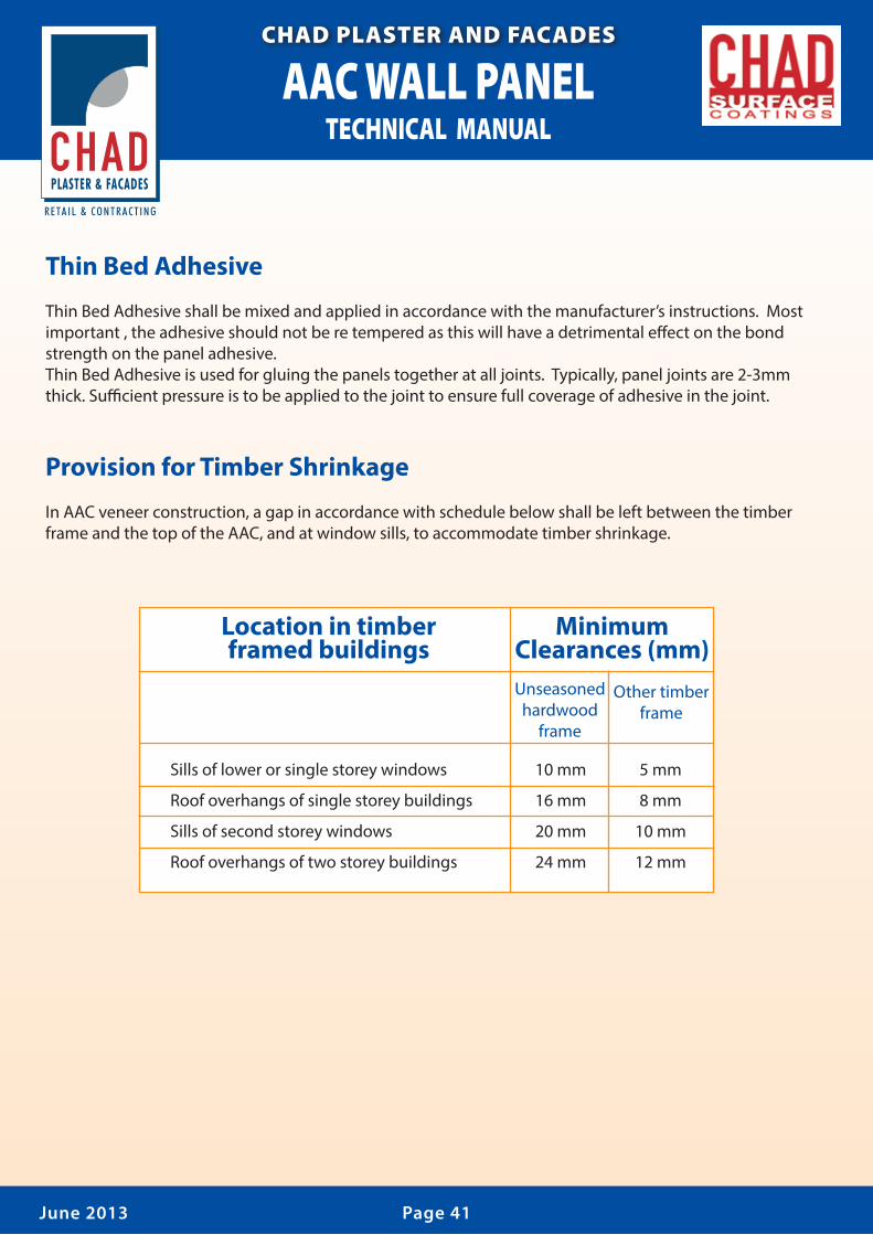
Provision for Timber Shrinkage
In AAC veneer construction, a gap in accordance with schedule below shall be left between the timber frame and the top of the AAC, and at window sills, to accommodate timber shrinkage.
Page 41June 2013
Sills of lower or single storey windows 10 mm 5 mm
Roof overhangs of single storey buildings 16 mm 8 mm
Sills of second storey windows 20 mm 10 mm
Roof overhangs of two storey buildings 24 mm 12 mm
Other timber frame
Location in timber framed buildings
Minimum Clearances (mm)Unseasoned hardwood
frame

AAC WALL PANELTECHNICAL MANUALCHAD
PLASTER & FACADES
R E TA I L & C O N T R A C T I N G
CHAD PLASTER AND FACADES
Page 42June 2013
Extending Panels
ECO PANEL (AAC) panels may be extended up to 200mm by gluing additional pieces to them using thin-bed adhesive; provided both parts are supported by timber or steel battens (or similar) and the overall length between control or articulation joints does not exceed the values speci�ed above.
Render and Paint Schedule
The following render and paint system shall be applied to AAC walls. Refer to Render and Paint Speci�cation for suitable products (Appendix).
Substrate : Autoclaved Aerated Concrete (AAC) Finish : Acrylic-painted render. Performance: Water-resistant and vapor-permeable decorative coating, capable of bridging up to a 1 mm substrate crack. Surface Preparation: Clean, patch and remove any dags. Ensure that the surface is free of all incompatible materials, such as silicone sealants. If subject to sea spray or within 1 km of a surf coast, wash with clean fresh water to remove all traces of salt. First Coat: Skim coat 3 to 4 mm thick acrylic render, hawk or steel trowel to level small irregularities. Do not render over control joints. Second Coat: Primer suitable for acrylic overcoats. Dry for at least 45 minutes before applying further coat. Third Coat: Trowel-on or roll-on Chad Surface texture acrylic coating. Dry for 24 hours before applying further coat. Fourth Coat: Roller, airless spray or brushed 100% acrylic heavy duty durable membra.

AAC WALL PANELTECHNICAL MANUALCHAD
PLASTER & FACADES
R E TA I L & C O N T R A C T I N G
CHAD PLASTER AND FACADES
Page 43June 2013
Associated Materials ScheduleRenders and PaintsRenders and paints shall comply with the following::First Coat: Skim coat 2 to 4 mm thick acrylic render, hawk or steel trowel to level small irregularities.Second Coat: Primer suitable for acrylic overcoats.Third Coat: Trowel-on or roll-on texture acrylic coating.Fourth Coat: Roller, airless spray or brushed 100% acrylic heavy duty durable coating.
Speci�ed Complying product reference Contact for Requirements further details
Acrylic Render FR Render Chad Surface Coatings CHAD Plaster and Trade render Facades Pty LtdPrimer Prime Seal (03) 9544 8899 Textured acrylic Texture Coatings: CHAD Surface Coatings 1366 North Road coating Trowel-on Marble texture medium or coarse Oakleigh SouthAcrylic heavy Chad Surface Coatings Membrane Coating duty durable coating
Joint MaterialJoint material shall comply with the Drawings, National Construction Code of Australia and relevant Standard(AS 3700). Unless stated otherwise:
Backing rod for control joints, expansion joints and articulation joints shall be expanded polystyrene tube or bead or, rigid steel backing pro�le with closed cell foam adhered to the metal pro�le face.
Joint sealant shall be gun grade multi-purpose polyurethane sealant.
Control joints and articulation joints shall incorporate de-bonding tape.
Intumescent seals shall be one-part, water-borne, urethane polymer blended with acrylic co-polymer to give a tough and gunnable sealant capable of providing the requisite �re performance as speci�ed in the Drawings and/or National Construction Code of Australia as appropriate.

AAC WALL PANELTECHNICAL MANUALCHAD
PLASTER & FACADES
R E TA I L & C O N T R A C T I N G
CHAD PLASTER AND FACADES
Page 44June 2013
Damp Proof Course
Damp-proof courses (DPCs) shall comply with the Drawings, National Construction Code of Australia and relevant Standard (AS 3700, AS/NZS 2904). Unless stated otherwise damp-proof courses (DPCs) shall consist of one of the following options.
A material complying with the Standard AS/NZS 2904;
Embossed black polyethylene �lm of high impact resistance and low slip, with a nominal thickness of 0.5 mm prior to embossing, and meeting the requirements of the relevant Standard (Clause 7.6 of AS/NZS 2904);
Polyethylene coated metal damp proof courses with an aluminium core not less than 0.1mm thick, shall be coated both sides with bitumen adhesive enclosed in polyethylene �lm not less than 0.1 mm thick on each face, and has a nominal total thickness of not less than 0.5 mm prior to embossing;
Bitumen impregnated materials of not less than 2.5 mm thickness, that meet the requirements of the relevant Standard (Clause 7.5 of AS/NZS 2904), when used in walls that are not higher than 7.8 m above the level of the DPC;
Termite shields (with no penetrations) continuous throughout the wall or pier.Notes: Metal and metal-cored damp-proof courses and termite shields shall not be used in locations with saline ground water or subject to rising salt damp

AAC WALL PANELTECHNICAL MANUALCHAD
PLASTER & FACADES
R E TA I L & C O N T R A C T I N G
CHAD PLASTER AND FACADES
Page 45June 2013
Flashings
Flashings shall comply with the Drawings, National Construction Code of Australia and relevant Standard (AS3700, AS/NZS 2904).
Metal and metal-cored �ashings shall not be used in locations that expose them to saline ground water or rising salt damp.
Metal �ashings shall be compatible with the materials with which they are in contact, and shall not give rise to electrolytic action. If there is potential for electrolytic action to occur, �ashings shall be isolated by inert materials.
Flashings intended to hold their shape shall be manufactured from rigid material. (e.g. metal cored material)
Unless stated otherwise �ashings shall consist of one of the following options:Flashing in Concealed Locations (e.g. cavity �ashings) shall be one of the following: Uncoated annealed lead having a mass not less than 10 kg/m in lengths not exceeding 1.5 m, shall not be used on any roof that is used to catch potable water;
Uncoated copper having a mass not less than 2.8 kg/m and having a thickness of 0.3 to 0.5 mm;
Bitumen coated metal (normally aluminium) with a total coated thickness of 0.6 mm to 1.0 mm;
Zinc coated steel with a thickness not less than 0.6 mm;
Embossed/quilted polyethylene sheet with an average thickness not less than 0.5 mm
Flashings in Exposed Locations (e.g. �ashings from the roof to wall) shall be one of the following:
Uncoated annealed lead having a mass not less than 20 kg/m in lengths not exceeding 1.5 m, but shall not be used on any roof that is used to catch potable water;
Uncoated copper having a mass not less than 2.8 kg/m and having a thickness of 0.3 to 0.5 mm;
Bitumen coated metal (normally aluminium) with a total coated thickness of 0.6 mm to 1.0 mm;
Zinc coated steel of thickness not less than 0.6 mm.

AAC WALL PANELTECHNICAL MANUALCHAD
PLASTER & FACADES
R E TA I L & C O N T R A C T I N G
CHAD PLASTER AND FACADES
Page 46June 2013
Slip Joint Material
Slip joint material shall comply with the following requirements. Metal slip joint materials shall notbe used in locations that are subject to rising salt damp.
Bitumen-coated aluminium
Embossed polyethylene
Polyethylene-and-bitumen coated aluminium.
Reinforced Concrete Lintels
Reinforced concrete lintels shall comply with the Drawings, National Construction Code of Australia and relevant Standard (AS 3700, AS 3600).
Anchorages
Anchorages shall comply with the Drawings, National Construction Code of Australia. Mechanical expansion anchors shall not be used where the expansion action is likely to damage the AAC.

AAC WALL PANELTECHNICAL MANUALCHAD
PLASTER & FACADES
R E TA I L & C O N T R A C T I N G
CHAD PLASTER AND FACADES
Page 47June 2013
Cladding of a Domestic Dwelling
The following speci�cation and details are generally suitable for Reinforced AAC wall cladding for domestic dwellings, subject to con�rmation by the Design Engineer. A suitable support framing system must also be provided.
Reinforced AAC Panels shall be screw �xed to horizontal light-gauge steel battens, which are �xed to vertical steel studs. There shall be not less than four horizontal battens per panel, with this number increasing for higher wind loads and for panels within 1,200 mm of the building corners.
Panels within 1,200 mm of each end of each external wall of a building (i.e. the two 600 mm wide panels closest to the corners) are subject to higher local wind pressures and suctions, and therefore require more battens and more screw �xing than other panels.
Unless speci�ed otherwise by the engineer, the following details and tables shall be used for the cladding of domestic dwellings with 75 mm thick or 100 mm thick Reinforced AAC Panels.
Light gauge steel battens shall comply with the Drawings, Building Regulations and relevant Standards (AS/NZS 4600, AS 3623). Cold-formed sections and accessories shall be manufactured from Z350 galvanised steel (Grade G550) complying with AS 1397, with a zinc coating not less than 350 g/m2 and shall comply with AS4600. All battens shall be 24 x 30 x 0.55 BMT Top Hat, Grade G550) or equivalent.
All screws shall be No 14 x 100 mm Bugle-headed batten self drilling galvanised steel screws, �xed from outside of the building through the AAC panels into the horizontal steel light gauge battens behindGeneral Notes:
1. All wind classi�cations and ultimate pressure calculations are based AS 4055-2006. 2. If AAC Panels are required to provide racking resistance, the screws and supports shall be determined by the structural engineer, taking into account the wind classi�cation and the overall building dimensions. 3. Top and bottom battens shall be positioned within 150 mm of the ends of the panels

AAC WALL PANELTECHNICAL MANUALCHAD
PLASTER & FACADES
R E TA I L & C O N T R A C T I N G
CHAD PLASTER AND FACADES
Page 48June 2013
Appendix
Party Wall Applications

AAC WALL PANELTECHNICAL MANUALCHAD
PLASTER & FACADES
R E TA I L & C O N T R A C T I N G
CHAD PLASTER AND FACADES
Page 49June 2013
In the preparation of these speci�cations and drawings, the following convention has been adopted.
All building design and construction must comply with the relevant National Construction Code of Australia and any relevant Standards referred to therein.
The structural behaviour of the AAC panels and the associated screw connections have been determined by bending and pullout tests carried out in Australia, which have been analysed in accordance with AS/NZS 1170.0 Appendix B and the following document: Aroni, S., de Groot, G.J., Robinson, M.J., Svanholm, G., & Wittman, F.H. (Editors), “RILEM Recommended Practice – Auto claved Aerated Concrete – Properties, Testing and Design”.
If either of the above do not cover the construction, then it should comply with a balanced combination of current practice, engineering principles and supplier’s information.
The structural behaviour of the AAC panels and the associated screw connections have been determined by bending and pullout tests carried out in Australia, which have been analysed in accordance with AS/NZS 1170.0 and the following document: Aroni, S., de Groot, G.J., Robinson, M.J., Svanholm, G., & Wittman, F.H. (Editors), “RILEM Recommended Practice – Autoclaved Aerated Concrete – Properties,

AAC WALL PANELTECHNICAL MANUALCHAD
PLASTER & FACADES
R E TA I L & C O N T R A C T I N G
CHAD PLASTER AND FACADES
Page 50June 2013
Single Storey Construction - Detail Panel Supported at Base
Single Storey Construction Details
Single Storey Construction - Detail Panel Suspended

AAC WALL PANELTECHNICAL MANUALCHAD
PLASTER & FACADES
R E TA I L & C O N T R A C T I N G
CHAD PLASTER AND FACADES
Page 51June 2013
Single Storey Construction - Hip Roof Elevation
Single Storey Construction - Gable End Elevation
NOTE1. Number of top hats and top hat spacing to be con�rmed by the building designer.
2. Additional top hats may be required, refer to Section 5.
These details have not shown the set-out of top hats to accomodate control joint locations. This is the responsibility of the building designer.
Additional Battons may be required

AAC WALL PANELTECHNICAL MANUALCHAD
PLASTER & FACADES
R E TA I L & C O N T R A C T I N G
CHAD PLASTER AND FACADES
Page 52June 2013
80mm Min.(Max. panel overhang is 25mm)
Single Storey Construction - Typical Section Detail
Penetration through ACC Panel for services should be neatly drilled and the joint sealed with a polyurethane sealant

AAC WALL PANELTECHNICAL MANUALCHAD
PLASTER & FACADES
R E TA I L & C O N T R A C T I N G
CHAD PLASTER AND FACADES
Page 53June 2013

AAC WALL PANELTECHNICAL MANUALCHAD
PLASTER & FACADES
R E TA I L & C O N T R A C T I N G
CHAD PLASTER AND FACADES
Page 54June 2013
Additional Battons may be required
FGL
FGL
Top hat section beyond
Top hat section beyond
Slab Level
Slab Level
Top of panel

AAC WALL PANELTECHNICAL MANUALCHAD
PLASTER & FACADES
R E TA I L & C O N T R A C T I N G
CHAD PLASTER AND FACADES
Page 55June 2013
Reinforcedconcrete slabReinforced
concrete slab
Reinforcedconcrete footing
Reinforcedconcrete footing
Top of windowTop of window
Steel stud frameTimber stud frame
Top hat sectionTop hat section
Timber joist
50 Min.50 Min.
Steel joist
Refer to Detail GRefer to
Detail G
Refer to Detail Page 63
Refer to Detail Page 63
De�ection gapsee below

AAC WALL PANELTECHNICAL MANUALCHAD
PLASTER & FACADES
R E TA I L & C O N T R A C T I N G
CHAD PLASTER AND FACADES
Page 56June 2013
Secon Story Addition

AAC WALL PANELTECHNICAL MANUALCHAD
PLASTER & FACADES
R E TA I L & C O N T R A C T I N G
CHAD PLASTER AND FACADES
Page 57June 2013
Top of windowTop of window
Timber stud frame Timber stud frame
Top hat sectionTop hat section
Timber �ooring
Refer to Detail G
Refer to Detail Pg 63
Refer to Detail Pg 63
Refer to Detail G
Existing double brickwork
Existing timber frame
Existing brick veneer
Reinforcedconcrete slab
Reinforcedconcrete footing
Reinforcedconcrete footing
Reinforcedconcrete slab
FGLFGL DPCDPC
AAC Eco panelAAC Eco panel
250
Max
.

AAC WALL PANELTECHNICAL MANUALCHAD
PLASTER & FACADES
R E TA I L & C O N T R A C T I N G
CHAD PLASTER AND FACADES
ACC Panel Fixing & Installation Detail
Internal Fixing Detail External Fixing Detail
NOTE1. When positioning the stud frames allow 5-7mm extra cavity width for the sheet bracing between top hat and timber stud.
2. Internal Fixing Detail not suitable when sarking/air barrier or sheet bracing systems are being used.
Screw Layout Drawing
™
SCREW LAYOUT
Page 58June 2013
Panel butt joined& glued with ACC paneladhesive

AAC WALL PANELTECHNICAL MANUALCHAD
PLASTER & FACADES
R E TA I L & C O N T R A C T I N G
CHAD PLASTER AND FACADES
Page 59June 2013
™
™
Timber orsteel studframe
Timber orsteel studframe
Timber orsteel studframe
250 max.
250 max.
75 Min.
75 Min.
50 Min.
DPC
DPC
DPC
FGL
FGL
Fill
FGL
Reinforcedconcrete slab
Reinforcedconcrete slab
Brickwork to underside of slab
Reinforcedconcretefooting
Reinforcedstrip footing
Timber or steel stud frame
Engagedbrick piers
Refer to Note ?
AAC Eco panel
Feature mouldingblock glued & screwedto panel
Polyurethene air sealopen cell foam
De�ection gap toallow for shrinkagein timber �oor
Brickwork tounderside of panel
Reinforcedstrip footing
FGL
Ant Cap
Reinforcedconcretefooting
Footing Fixing Details
Detail ADetail B
Detail DDetail C

AAC WALL PANELTECHNICAL MANUALCHAD
PLASTER & FACADES
R E TA I L & C O N T R A C T I N G
CHAD PLASTER AND FACADES
Page 60June 2013
Ant cap withDPC under
Backing rodPolyurethane sealant
Approved termite barriersystem as required
(expressed at outsidesurface)
Brick pierAllow to coat
20 Clear
Backing rod
Polyurethane sealant
AAC Eco panel
FGL
Reinforcedconctrete slab
>20mm and <75mm
Footing toengineer’s detailsProvide suitable physical
or chemical barrier inaccordance with AS 3660
FGL
Coat panel with bitumen basedwaterproof paint wherein contact with ground
80 x 50 x 1.9mm galvanisedangle. 1-M6 Dynabolt@ 600 cts (2Min.)
3/14-10 x 95mm HexHead self-drilling screwsat each end of panel
Fix 100 x 75 x 8mmgalvanised angle to
piers (Max. 2m centres)with 1-M12 at each end
minimum bearing of panelon angle is 40mm
Footing Fixing Details continued
Detail E
Detail F

™
™
AAC WALL PANELTECHNICAL MANUALCHAD
PLASTER & FACADES
R E TA I L & C O N T R A C T I N G
CHAD PLASTER AND FACADES
Top of window orexternal doors 50 Min.
Timber stud orsteel stud frame
AAC Eco panel
10mm min.de�ection gap
Flashing
25 mm
StudFrame
Stud frame
WallFrame
Flashing to projectspeci�cation
Apply Fullers Fulaprene 303 to angle before screw �xing
Fix �ashingto stud frame
with nails or screws
Wall support to engineer’s detail (if required) or joists designed for loading
50-75mmGalvanised orPVC angle(epoxy primer tobe used over gal,then acrilicwaterpro�membrane)
Waterproof membraneover �oor and continue angle
AAC Eco panelsupported via top hat battens
Exposed reiforcing coated withFentak touch up paint
Metal or lead �ashingdepending on roof material
Iron or tile roof material
Eaves
Carry coatingpast eave line
5 - 10mm gapfor drainage
Timbermould
150 Max.
Page 61June 2013
Wall Junction Details
Details G
Details J
Details I

AAC WALL PANELTECHNICAL MANUALCHAD
PLASTER & FACADES
R E TA I L & C O N T R A C T I N G
CHAD PLASTER AND FACADES
Page 62June 2013
NOTE1. Galvanised steel angle required if additional top hats are not installed.
2. Additional top hats may be required.
Gable End Wall DetailGable End Wall Detail - Lintel Over Window
™
Parapet Capping Beam Penetration Detail
NOTEParapet capping shall be designed and fastened in accordance with SAA – HB39 1997 – Installation Code for Metal Roo�ng and Wall Cladding. Stop ends shall be incorporated to all �ashings.
Beam penetration through wall
10mm
10mm gap to allow for movement, filled with external gradePolyurethane sealantACC Panel
ACC Panel
ACC Panel
ACC Panel
Details L
Details K
Details M Details N

AAC WALL PANELTECHNICAL MANUALCHAD
PLASTER & FACADES
R E TA I L & C O N T R A C T I N G
CHAD PLASTER AND FACADES
Page 63June 2013
Details O Details P
Details Q Details R
Details S
Control Movement Joint Detail
Featuremoulding�xed totop panel50x50 polyurethane air seal opencell foam
Temporary timber packer during construction onlyRemove oncompletion
De�ection gapas per projectspeci�cation
Recessed toallow formovement
Recessed toallow formovement
De�ection gapas per projectspeci�cation
50x50polyurethaneair seal opencell foam
Temporarypacked forconstructiononly removeon completion
Temporarypacked forconstructiononly removeon completion
50x50polyurethaneair seal opencell foamDrip groove
in coatingDrip groovein coating
Top hatsection
Coatingsystem Backing rod Polyurethane
sealant
Featuremoulding gluedto top panelwith suitableadhesive& mechanical�xing
Featuremoulding gluedto top panelwith suitableadhesive& mechanical�xing
De�ection gapas per projectspeci�cationDrip groovein coating
Coating system
Polyurethanesealant
50mm Able�ex
Coating system
Recessed to allow for movement

AAC WALL PANELTECHNICAL MANUALCHAD
PLASTER & FACADES
R E TA I L & C O N T R A C T I N G
CHAD PLASTER AND FACADES
Page 64June 2013
™™
™
™
™ ™
™
Door & Window Fixing Details
™
NOTE1. The detail above DOES NOT represent a true
control joint but provides a solution where the width of the window is 10-15mm wider than the total number of ACC Panels installed under the windows.
2. Detailing of coating system at dummy joint & control joint to coating system manufacturer’s speci�cation.
3. Depth and width of sealant and installation to be in accordance with the manufacturer’s speci�cation.
NOTE1. If a control joint is required, it must be installed regardless.2. For heads above hinged doors, adopt these guidelines.3. For sliding glass doors, always place a control joint at both sides of the head.4. For glued joint, ensure the top hats running behind the head and/or sill are �xed to the full height vertical ACC Panel.
Typical Window Detail - No Lintel Over Typical Window Control Joint Detail - Lintel Over
Head Sizes Detail
NOTE1. The installation sequence of the ACC Panels
around the openings should be followed as numbered above, to maintain glue thickess on the edge of the ACC Panels.
2. Detailing of coating system at dummy joint & control joint to coating system manufacturer’s speci�cation.
3. Depth and width of sealant and installation to be in accordance with the manufacturer’s speci�cation.
ACC Panel
ACC Panel
ACC Panel
Detail T Detail U
Details V

AAC WALL PANELTECHNICAL MANUALCHAD
PLASTER & FACADES
R E TA I L & C O N T R A C T I N G
CHAD PLASTER AND FACADES
Page 65June 2013
Waterproof surface prior to coating
Aluminium sliding window
Timber revealSealant
Timber studSill Block
Waterproof surfaceprior to coating
Waterproof surfaceprior to coating
™
™
™
Waterproof surfaceprior to coating
Waterproof surfaceprior to coating
Typical Window Sill Detail - Aluminium Window Frame
Header Detail
NOTEDrainage of window and door sills, in either aluminium or timber, should be directed to the outside of the building, on top of the window sill. AAC recommends waterproo�ng the AAC surface around the perimeter of the window opening. Provide an overlap of the waterproof coating and the external coating.
Alternative Window Sill Detail - Timber Frame Window
Sill Detail
Garage Head Detail
Waterproof surface prior to coating
Aluminium sliding window
Timber revealSealant to gap & below black strip
Timber frame
Sill Block
Top Hats
Typical Window Sill Detail & Timber Window Frame
Lintel overGarage
Sealant
Fibre cement
GyprockPlasterboard
Top Hats
Corner mould prior to coating
Nail fibre cement totimber and
Construction adhesive, ie. Max Bond or similar
ACC Panel
AAC Panel
AAC Panel adhesive
AAC
AAC Panel
AAC Panel
AAC Panel
Detail WDetail X
Detail Y
Detail Z
Detail AB
Detail AA

AAC WALL PANELTECHNICAL MANUALCHAD
PLASTER & FACADES
R E TA I L & C O N T R A C T I N G
CHAD PLASTER AND FACADES
Page 66June 2013
Sliding Door Sill Detail - Elevation View
Poured concrete
as infill below sliding door
Sliding Door Sill Detail - Section View Timber Door - Jamb Detail
AAC Panel
AAC PanelAAC Panel
Detail AC
Detail AD
Detail AE


™
™
Timber orsteel studframe
Timber orsteel studframe
Timber orsteel studframe
250 max.
250 max.
75 Min.
75 Min.
50 Min.
DPC
DPC
DPC
FGL
FGL
Fill
FGL
Reinforcedconcrete slab
Reinforcedconcrete slab
Brickwork to underside of slab
Reinforcedconcretefooting
Reinforcedstrip footing
Timber or steel stud frame
Engagedbrick piers
Refer to Note ?
AAC Eco panel
Feature mouldingblock glued & screwedto panel
Polyurethene air sealopen cell foam
De�ection gap toallow for shrinkagein timber �oor
Brickwork tounderside of panel
Reinforcedstrip footing
FGL
Ant Cap
Reinforcedconcretefooting
