active damping of torsional vibrations in active damping of torsional vibrations in servodrives...
TRANSCRIPT

Servodrive drive with flexibility control structures digital control PI and PID controllers LQ compensator
state controller state observer SRR controller Kalman filter
Stefan BROCK Jan DESKUR Dariusz JANISZEWSKI Roman MUSZYNSKI
ACTIVE DAMPING OF TORSIONAL VIBRATIONSIN SERVODRIVES
In the paper the problems of active damping of torsional vibrations in small power high dynamicservo drives are presented Only solutions with position sensor (encoder) i e without other sensor aretaken into consideration Eventual observers or estimators of state variables needed for control as wellas all elements of signal processing are treated as a integral part of the controller The total time delayintroduced into speed control loop due to digital control and processing is important factor from pointof view of ability for active damping of vibration The adequate stiffness factor together with natu-ral torsional frequency anti-resonance frequency and load-to-motor inertia ratio are used as general-ised parameters of the system The aim of the work is to test the ability of various speed controllersfor damping of the vibration in the system at various values of its stiffness and inertia The followingstructures of speed controller are taken into consideration and preliminary tested the digital PI andPID controllers the state controller with state observer slow resonance ratio controller and linearquadratic compensator with Kalman filter In all cases there are given the proposed control structuresand results obtained by the authors during their preliminary simulation investigation Conclusionsrelated to the operation of the separate controllers and further investigations are given
1 INTRODUCTION
Torsional vibration can occur in every drive because of flexibility of mechanicalcoupling between the motor and the load Vibration problem must be taken into con-sideration while designing speed and position controllers Numerous works concernedhigh power drives with long mechanical shafts Natural torsional frequencies in suchdrive are low Dynamics of torque control loop for high power drives is also relativelylow with bandwidth not exceed tens Hz Auxiliary sensors are often used in controlsystems for better damping of torsional vibrations Low-power high-dynamic servo-
Poznan University of Technology Institute of Control and Information Engineering
ul Piotrowo 3A 60-965 Poznan POLAND stefanbrockputpoznanpljandeskurputpoznanpl dariuszjaniszewskiputpoznanpl romanmuszynskiputpoznanpl
Active damping of torsional vibrations in servodrives_____________________________________________________________________
drives require other solution of vibration problems The following characteristics ofservodrives must be necessarily considered
Natural torsional frequencies are relatively high (can be higher than 100Hz)ndash Torque (or current) control loop is very fast The setting time can be less than
1ms and the bandwidth can reach a few kHzndash Rotational speed is not measured directly The motor is equipped with position
sensor (encoder) only Its quantisation error not only influences the accuracy ofposition control but also degrades the quality of speed estimation and control
ndash Digital controller samples position signal and makes calculations repetitivelywith sampling period Ts Time delay introduced into speed control loop by digitalprocessing of signals must by carefully taken into consideration
If possible the speed controller should actively damp torsional vibrations The abilityof active damping depends on delays in control loop as well as on mechanical parame-ters According to European Standard IEC 61800-42002 active damping is possible un-der the following conditions
ndash The pass-band frequency of torque controller loop must be at least two timeshigher than natural torsional frequencies (NTF) of the drive
ndash Time delay in speed measurement system should be considerably smaller than therise time of the electromagnetic torque
ndash Accuracy of speed measurement should be highThe first condition is usually fulfilled in servodrive systems the other conditions
are more problematic In contrast to high power drives the difficulties in active dam-ping result mainly not from poor dynamics of torque control loop but from lack ofspeed measurement and from delays caused by digital signal processing This is thereason we have decided to choose the product of the lowest natural torsional frequen-cy NTF by the sum T of all delays in the speed control loop as a ldquostiffness factorrdquoAnother relative factor characterising difficulties in active damping is the ratio R ofthe load inertia JL to the motor inertia JM The aim of this work is to test the activedamping ability of speed control loop designed with various methods in the widerange of R and TmiddotNTF
2 MODELS OF SERVODRIVE WITH FLEXIBLE SHAFT
21 TWO-MASS SYSTEM
Mechanical system is basically a non-linear distributed parameter system whichcan be modelled as several inertia moments non-linear springs and non-linear damp-ers Simpler models are desired for synthesis of the controller Non-linear phenomenasuch as backlash and stick-slip can be neglected as the mechanical design of servo-
Active damping of torsional vibrations in servodrives_____________________________________________________________________
drive minimises both of them Mechanical damping is very low and can be also ne-glected In many cases the model of mechanical part can be reduced to the linear two-mass system shown in Fig 1
mM ωM JM Ksh msh JL mL ωL
Fig 1 Two-mass system its natural parameters torque and velocity denotation
The elastic shaft with torque-to-torsion ratio equal to Ksh couples motor inertia JM
and load inertia JL The system can be described with the following equations
shMM
M mmdt
dJ minus=ω
(1)
LshL
L mmdt
dJ minus=ω
(2)
LMsh
dt
d ωωθ minus= (3)
MM
dt
d ω=θ (4)
shshsh Km θsdot= (5)
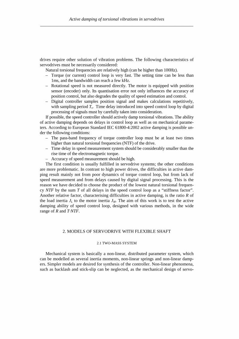
where ωM and ωL are the motor and the load shaft angular speed respectively SymbolsmM and mL mean the motor and the load torque and msh and θsh are the torque transfer byelastic shaft and elastic shaft torsion angle respectively Two-mass system can be rep-resented by block diagram shown in Fig2
The model of two-mass system can be transformed into matrix transfer functionform Conjugate imaginary poles and zeros are defined by two parameters (6 7) theanti-resonance frequency ARF and the natural torsional frequency NTF
sdot
LMsh
L
sh
J+
JK
π=NTF
J
K
π=ARF
11
2
1
2
1 (6 7)
The inertia ratio can be expressed as a function of ARF and NTF as follows
Active damping of torsional vibrations in servodrives_____________________________________________________________________
Fig 2 Block diagram of two-mass system
12
minus
ARF
NTF=
J
J=R
M
L (8)
22 SPEED CONTROL LOOP
Only the speed control loop not position control is considered The system consistsof the torque control loop sensors and speed controller As the current control in themodern drives is rather fast the torque control loop is treated as almost ideal unity gainblock with delay Tm From the practical point of view all solutions with sensors installedon the load side should be rejected Only encoder integrated with the motor can be usedfor control purpose Its quantisation error has influence on the quality of control andshould be taken into consideration at simulation and design of the system for high-dynamic servodrives Position encoder does not measure angular velocity In order tohave the velocity signal the digital processing of the position one is needed The speedcontroller samples position signal with period Ts and calculates the speed estimate bydirect or indirect differentiation This process introduces the delay into the control sys-tem Controller output is usually updated one period Ts later than input is sampled Theoutput signal is then extrapolated over the next Ts period All these operations introduceadditional delay into control circuit The total delay T can be calculated as follows
smsss
mcdθexm T+T=T+T
+T
+TT+T+T+T=T sdotasymp 222
(9)
whereTm ndash delay of torque control loop Tex ndash delay caused by extrapolation of speed con-troller output Tdθ ndash delay introduced by filtered differentiation of position signalTc ndash controller delay from input sampling to output updating
Active damping of torsional vibrations in servodrives_____________________________________________________________________
The general block diagram of the speed control loop is shown in Fig 3 The control-ler is modelled in the discrete-time domain while the rest of the loop in the continuous-time domain All delays due to digital processing are represented directly in the con-troller model Apart from the linear blocks represented by G(z) the diagram includestwo non-linear ones the quantiser of the position measurement signal θM and the limiterof the torque reference signal mrd All signals used in discrete-time domain are mark outby additional subscript d Such non-linear model has been used in simulation experi-ments However most of design methods for speed control base on linear and homoge-neous models (all-digital or all-continuous) In such models the both mentioned abovenon-linearities can be taken into consideration as factors limiting the range of possiblechoices of controller gains Non-linear quantisation block can be substituted by the in-dependent source of quantisation noise This noise amplified by the controller must notactivate output limiter at any working conditions In the all-continuous-time model de-lay caused by the position differentiation sampling and extrapolation should be repre-sented by additional delay block or included to the model of torque control loop
Fig 3 General block diagram of speed control loop
Additional input to the controller marked with dashed line is designated for testingpurposes The disturbing signal mdd can excite oscillating modes much more effectivelythan changes of load torque Moreover practical implementation of an internal torsionexcitation test is very simple as compared to a real one The setting time of the motorspeed ωM after step change of the mdd has been chosen as a measure of active dampingability of the speed controller
Active damping of torsional vibrations in servodrives_____________________________________________________________________
3 PI PID CONTROLLERS
31 TRANSFER FUNCTIONS OF IPD CONTROLLERS
Proportional-integral and proportional-integral-derivative controllers PI PID arethe simplest and the most commonly used Feedback transfer function (from θMd tomrd) of discrete-time PID speed controller can be expressed as follows
( )( ) ( ) ( )
zz
z
T
T+
z
z
T
T+K
zT
z=
zzCzH=
zθ
zm
s
d
i
sp
sMd
rd 11
11
11 sdot
minusminus
sdotminusminussdotsdotminus (10)
The first term H(z) is the transfer function of the first-order-differentiating filterwhich transforms the measured position signal θMd into the speed feedback signal ωMdThe medium term C(z) expresses the digital PID algorithm The last term 1z delaysthe controller output by one Ts period In case of PI controller the derivative time-constant Td is zero and one reduces the order of the controller
Reference transfer function (from ωrd to mrd) does not need to be exactly the samelike feedback transfer function C (z)z This additional degree of freedom gives op-portunity to independently shape the response to feedback signal and the response toreference signal The ability of active damping depends on the feedback transmit-tance only The reference transfer function of two-degree-of-freedom (2DOF) PIDcontroller can be arbitrarily chosen provided that the integral term is exactly the sameas in C(z) The simplest choice is to neglect all other terms
( )( ) ( )
zz
z
T
TK=
zzF=
zω
zm
i
sp
rd
rd 1
1
1 sdotminus
sdot (11)
Such controller sometimes called ldquoIPD controllerrdquo assures fast response to feed-back signal as well as soft reaction on step change of the speed reference signal Softreaction is desirable in order to avoid excitation of the torsional vibrations
Transfer functions C(z) and F(z) can be re-arranged and combined together inmany different ways Block diagram of the proposed unconventional IPD controller ispresented in Fig4 The output signal is the limited integral of the sum of components(P+D+D2) Therefore any separate anti-wind-up circuit is not necessary
Active damping of torsional vibrations in servodrives_____________________________________________________________________
Fig4 Block diagram of the proposed IPD controller
32 ACTIVE DAMPING WHEN DELAYS ARE NEGLIGIBLE
Speed control of two-inertia system by the PIPID controller was analysed in [21]using the pole placement method Delays were neglected ideal speed feedback wasassumed and the fourth-order continuous-time domain model represented the wholesystem An arbitrary placement of the poles of the closed speed control loop was notpossible for the flexible coupled drive However it was found that good dampingcould be obtained for limited range of drive parameters Three different methods ofchoosing pole location were proposed The method assuming equality of the real partsof both complex pole pairs seemed the most promising The damping coefficient ξ1for one pole pair could be chosen as design parameter while the second oneξ2 resulted from the mentioned equality The PI controller set up according to thismethod was able to damp vibration for the inertia ratio within the range of 1 lt R lt 4
Several analyses and simulations have been carried out to find the parameters of PIcontroller at which the shortest setting time is obtained for each value of inertia ratioR It has been found that the damping coefficient ξ1 of the slower pole pair should beset to the value higher than 08 for R gt 15 and to about 064 for R=1 The perform-ance of PI control in the range of 15ltRlt4 can be characterised by the followingfeatures
ndash Setting time is about 15 ARFndash Speed drop ∆ωmax after step change of the load torque mL is about 5middotARFmiddotmLKsh
The authors [21] proposed PID control if the inertia ratio R is greater than 4 or lessthan 1 The derivative action should virtually reduce the motor inertia JM to the newvalue JM at which the inertia ratio R is sufficient for PI control Controller gain Kp andtime-constant Ti can be calculated as previously provided JM (virtual inertia) is usedinstead of real value JM
Active damping of torsional vibrations in servodrives_____________________________________________________________________
33 ACTIVE DAMPING WHEN DELAY CONSIDERED
Numerous simulation experiments have been carried out in order to find the rangeof delay at which the PIPID controller set up according to previously describedrules could be used The results of this investigation are shown in Fig 5 and can besummarised as follows
ndash Delay TmiddotNTF not greater than 01 is acceptable for the inertia ratio in the range1ltRlt4 In that case the performance is only slightly degraded but the delay mar-gin is low Even the 15 increase in delay can be enough to make the system un-stable
ndash For the inertia ratio higher than 75 or lower than 05 even very small delaysTmiddotNTFlt005 can not be neglected
Fig 5 Active damping with controller parameters dependent only on R a) gain and time-constants
b) stability boundary as function of R and TmiddotNTF c) setting time for various delays TmiddotNTF
Active damping of torsional vibrations in servodrives_____________________________________________________________________
Fig 6 Active damping with controller parameters dependent on R and delay a) gain Kpb) integral time-constant Ti c) derivative time-constant TD
d) setting time after step change of virtual disturbance torque mdd
The aim of further work was to widen the range of admissible delays by changingthe controller parameters Considerable improvement has been achieved Optimal set-tings of Kp Ti Td shown in Fig 6 a b c as a function of both R and TmiddotNTF havebeen found by simulations experiment The characteristics of setting time shown inFig 6 d and can be summarised as follows
ndash Stable operation is possible in the wide investigated range of parameters025ltRlt8 0ltTmiddotNTFlt04
ndash For moderate delays (TmiddotNTFlt015) the performance is slightly better than previ-ously for no-delay conditions
ndash For higher values of total delay (TmiddotNTFgt015) the setting time can be considera-bly longer
Exemplary waveforms showing damping ability of the IPD controller set up ac-cording to Fig 5 and Fig 6 are presented in Fig7
Active damping of torsional vibrations in servodrives_____________________________________________________________________
4 STATE CONTROLLER WITH STATE OBSERVER
41 STRUCTURE OF THE SYSTEM
The state controller is one of the classical solutions of the control task It is oftenused also for the systems with flexibility [1] [2] [3] [12] and [20] According to as-sumption of this work many structures of the system with state controller intended forhigh power drives should be rejected because of additional sensors installed on the loadside The structure using only the position encoder integrated with the motor is shown inFig 8 There are elements of digital processing (sampler differentiation procedure) ofposition signal in the feedback path of the model They introduce to the path the delay Tf
equal to the time step Ts of the DSP controller Other blocks in the model are simulatedin continuous-time domain Their delays are included to the block modelling torquecontrol loop (total delay Tg of the block)
The state controller uses the signals of motor mM and shaft shm torque as well as
motor ωMd and load Lω speed The feedback from signal mM is easy to realise as themotor torque is usually proportional to the current (whose signal is measurable) In somecases the reference torque mr can be used instead of motor torque mM This solution cor-
responds to the controller shown in Fig 3 In order to have the signals shm and Lω thecontroller algorithm must realise also observer procedure In frame of presented on
Fig 8 controller it is also possible to test system without internal feedback signal shm or
Lω
Fig7 Waveforms of motor speed ωM and load speed ωL as responses on step change of reference
speed ωrd and following step change of signal mdd a) with controller set up according to [21] and
Fig5 a b) with proposed settings according to Fig 6 (R=2 TmiddotNTF=011)
Active damping of torsional vibrations in servodrives_____________________________________________________________________
z
11minus
sT
1 θMd
Differentiation Sampler
Quantiser
Digital processing delay Tf = Ts
Statecontroller
gsTeminus
2-masssystem(fig 2)
θM
mL
mM
Torque control loop inclu-ding additional delay
mr
Stateobserver
shm
Lω
ωMd
ωr
mM bull
bull
bull
Fig 8 Model of the system with state controller and state observer
42 THE STATE CONTROLLER
The linear state controller operates according to the equation
LLshshMdMMmrr ωkmkωkmkωkm minusminusminusminus= ω (12)
where the gains of component with reference motor and load speed should fulfil therelation
LM kkk +=ω (13)
in order to have no load operation without speed error Therefore if
ωkakM sdot= (14)
then
( ) ωkakL sdotminus= 1 (15)
Active damping of torsional vibrations in servodrives_____________________________________________________________________
where the a is the weight of the motor speed feedback and 1ndasha is the weight of the loadspeed feedback The coefficients kω a km and ksh are the parameters of the controllerinfluencing the properties of the system These parameters are selected using optimisa-tion procedure as described in subchapter 44
Instead of the linear state controller the non-linear one described in [16] can be usedIt should give further improving the properties also in the systems with delay
43 THE STATE OBSERVER
The observer (Fig 9) contains the two-mass model (Fig 2) and correction elements
Reduction of the error between the motor speed ωMd and speed Mω from the observer tothe value near by zero allows reproducing the signals of the load speed ωL and shafttorque msh A quality of it depends on the gains h1 h4 In order to reproduce the loadtorque mL the error of the observation of motor speed is integrated in the circuit with thegain h4
The signal Lm can be used in the observer for compensation of the speed drop due to
loading the drive For this purpose the signal Lm should be introduced to the torquesumming point (dashed line in the Fig 9) with positive gain hL The principle of thiscompensation is given in [10] together with derivation of the following condition
m
shL k
kh
++=
11 (16)
at which the speed is invariant with regard to loading
44 RESULTS OF THE PRELIMINARY SIMULATION
Preliminary the system from Fig 8 was simulated without the observer i eksh=kL=0 and a = 1 The inertia ratio was R = 1 During investigation the total delay Twas varied Every time the T was divided in two parts Tg = 2T3 and Tf = T3 Themaximum value of index TNTF was searched at which the controller is able active todamp the oscillations For each value of delay the gains kω and km of the controller wereoptimised The maximum ratio of two successive amplitudes of the oscillating quantitieswas the optimisation criterion
The results of the simulation are given in Table 1 It is seen that with increase ofstiffness (delay) the optimum value of feedback gains decrease Simultaneously the set-ting time becomes longer State controller having only motor speed and motor torque
Active damping of torsional vibrations in servodrives_____________________________________________________________________
Fig 9 The state observer
feedback paths is able to damp the oscillation in the system with stiffness up to about023 (the highest value in the Table 1)
A better result is expected after additionally feeding the controller from the observerwith the feedback signals of the shaft torque and load speed However the degree ofimprovement of system properties will depend strongly on encoder inaccuracy and alsoon delay as the observer uses non-actual values of the quantities
Table 1 The dependence of the controller parameters and setting time on thestiffness factor for the system with state controller having only two feedback paths
Stiffness factorTNTF 0101 0135 0169 0230
kω [Nsrad] 1 0556 0333 0133Controllerparameters km [-] 1 0667 0333 0167
Setting time multipliedby the ARF 113 163 424 very long
The controller parameters are relate to first data column
Active damping of torsional vibrations in servodrives_____________________________________________________________________
5 SLOW RESONANCE RATIO CONTROLLER
The slow resonance ratio control (SRRC) was firstly introduced as a method forvibration suppression and disturbance rejection in torsional systems [1] [6] [7]SRRC algorithm feeds back the torsional torque estimated by a model-based distur-bance observer so to change the virtual motor inertia to an arbitrary selected valueThis means that the resonance frequency NTF and then the resonance ratioH=NTFARF can be changed
Fig 2e-sT
JM
1-K
Differential
2DOF PI
LPF(Tq)LPF(Tq)
Differential
K+
++-
+-
digital speed controllerωrd
ωMd θMd
θM
mrd
mM
mL
mr
samplerquantizer
torque control loopand additional delay
2-mass systemextrapolator
msh^
Fig 10 Block diagram of resonance control
The detail of the resonance ratio control with shaft torque observer is reported inFig 10 where the mechanical model from Fig 2 has been used The digital speedcontrollerrsquos model has been simplified by fusion all delays in the closed loop torquecontrol Based on measurement motor speed ωMd and reference torque mrd the shaft
torque shm is estimated Only (1-K) portion of the estimated shaft torque is fed backBy doing this the designed virtual motor inertia JM-des is defined as
KJJ MdesM =minus (17)
This means that virtual inertia ratio Rdes can be expressed as
KRJJR LdesMdes sdot== minus (18)
Active damping of torsional vibrations in servodrives_____________________________________________________________________
The resonance ratio H could be changed to value desdes RH += 1
The slow disturbance observer was originally proposed by Iwata and Itoh [8]They proposed that the optimal cut-off frequency should be a little lower than theanti-resonant frequency ARF The optimal observer time constant Tq is calculated onbasis R and Rdes as given by [17]
ARFRRRR
RR
Tdesdes
des
q sdotsdot
++
++
++=
π21
21
43
1
4
31
When PI speed controller is used the characteristic equation of the closed drive sys-tem is
01
12
23
34
4)( asasasasasP ++++= (19)
The coefficients a4ndasha0 can be selected according to desired dynamical propertiesof whole system The effective method is Coefficient Diagram Method based on Ma-nabe polynomials [15] In this method design specifications are equivalent time con-stant (τ ) and stability indices (γi) For analysed system τ is defined as
01 aa=τ (20)
and stability indices should be selected as follow
2 2 5242
23
331
22
220
21
1 ======aa
a
aa
a
aa
a γγγ (21)
By solving these equations the optimal resonance ratio can be determined
580 sdot=desH This correspond to inertia ratio Rdes=115
From (18) the coefficient K is calculated The controller gains are given by (com-pare [7])
22
)(11
1611
220
ARFJK
ARFJK
Li
Lp
sdotsdotsdot=
sdotsdotsdot=
π
π
(22)
Active damping of torsional vibrations in servodrives_____________________________________________________________________
Simulation experiments has been carried out to find the range of stabile parameters atwhich presented SRRC could be used The results of this investigation can be summa-rised as followsStability boundary
- TmiddotNTF gt 012 for 08 lt R lt 2- TmiddotNTF gt 010 for 08 lt R lt 8- TmiddotNTF gt 003 for 035 lt R lt 8
Setting time Tω - ARF Tω lt18 for TmiddotNTF = 01 and 08 lt R lt 2- ARF Tω lt42 for TmiddotNTF = 008 and 2 lt R lt 8- ARF Tω lt51 for TmiddotNTF = 006 and 05 lt R lt 1
Presented slow resonance ratio controller is well fitting for system with relativelarge load inertia in relation to motor inertia In such case the virtual motor inertia isincreasing through using feedback coefficient K smaller than 1 and the whole systemis robust to real-time delays However if the load inertia is small feedback coeffi-cient K greater than 1 is needed and system is sensitive to any time lags It should benoted that when the motor inertia is much larger than the load inertia the resonanceratio control makes the disturbance response worse This fact suggests that the vibra-tion suppression and the disturbance rejection are opposite objectives [7]
6 LINEAR-QUADRATIC CONTROLLER WITH KALMAN FILTER
61 STATE AND DISTURBANCES OBSERVER
When using the LQ-controller state vector should be available State variables thatcannot be measured should be estimated
The Kalman Filter is one of proposed estimators [11] [12] [13] [17] Kalmanfilter theory allows estimating all state variables Theory presented in [11] determinesthe state variables They could be disturbed by Gaussian white noise which repre-sents all error sources and model inaccuracy [11] This is a narrow assumption thathas been avoided in his work This causes difficulties with theoretical tuning rules
Basing on filtering knowledge [11] the model of the system can be expressed bystate (23) and measurement (24) equations
1n e n e n nx x u w+ = + +A B (23)
n e n ny x v= +C (24)
Active damping of torsional vibrations in servodrives_____________________________________________________________________
where the control signal u is equal to the torque command mr and the output vector yis equal to mechanical position θ In equations (23) and (24) w represents a processnoise and v - measurement noise
It is assumed that the disturbing load torque (mL) is a part of measurement noiseand a part of state vector The assumption is only valid when the derivative of loadtorque is near to zero
0L
dm
dtasymp (25)
The state vector of observer has been extended by new estimated variable (Lm )
ˆˆ ˆˆ ˆ ˆT
M L sh Lx m mω ω θ = (26)
New state space matrices are equal
10 0 0 0
1 10 0 0
0 0 0
0 0 0 0 0
1 0 0 0 0
M
L Le
sh sh
J
J J
K K
minus minus =
minus
A
=
0
0
0
0
1
M
e
J
B
0
0
0
0
1
e
=
C (272829)
The equations of estimator are given by
( )| | 1 | 1
1| |
ˆ ˆ ˆ
ˆ ˆ ˆ
n n n n e n e n n
n n e n n e n
x x y x
x x u
minus minus
+
= + minus
= +
K C
A B (30)
where Ke is a Kalman filter gains which is computed by solving Ricatti equation[11] The gains can be calculated using recursive algorithm only one time and can bevalid for each step of control algorithm The noisersquos covariance of presented system(025ltRlt8 Ksh=1 equivalent of 14bit encoder) can be determine by matrix Qe
Active damping of torsional vibrations in servodrives_____________________________________________________________________
22
14
202 02 10 10
2e diag π =
Q (31)
which values represent covariances respectively with vector x elements The noisersquoscovariance of output signal may be described by
2
e 14
2
2R
π =
(32)
Theoretically the appropriate values should be real covariance but they was se-lected experimentally during system investigations It is noticed that last element ofQe matrix and Re is linked with the one known error It is caused by the quantisationduring obtaining real position from the 14-bit encoder
62 LQ CONTROL STRATEGY
The LQ-controller has several good properties [4] [9] and [18] It is applicable tomultivariable and time-varying systems when a model of the system can be availablein state space form (Fig 11) Changing the relations between the magnitude of ele-ments in weighting matrices we obtain compromise between the control speed and themagnitudes of control signals
Fig 11 Model of the system with LQ-controller and Kalman filter
The finding of answer presented in [9] is applicable to our system The generalformulation of the problem is to minimise the performance index J The following
Active damping of torsional vibrations in servodrives_____________________________________________________________________
deviations from steady state has been defined ∆x ∆u (for state and control variablesrespectively) The designed problem was reformulated to LQ-compensator with newdefined performance index J
( ) ( )( )2
0
T
r rJ R ux xinfin
= + ∆∆ ∆int Q (33)
where Qr and Rr are defined tuning matricesIn state controller the control-input signal is given by follows
r
xu
p
= minus
K (34)
Partitioning Kr and using integral control to cancel steady-state error
( )0
ˆt
M rdp dtω ω= minusint (35)
the control input signal yields
[ ] ( )1 2 3
0
ˆ
ˆ ˆ
ˆ
M t
L p M rd
sh
u K K K K dt
m
ωω ω ω = minus minus minus
int (36)
The main problem during solving LQ regulator is proper choosing the performanceindex J As shown in [9] Qr and Rr are given as
0 0
0 0
0 0 0 0
0 0 0
r
α αα α β
δ
minus minus + =
Q rR ε= (3738)
Performance index (33) can be expressed in more practical form
Active damping of torsional vibrations in servodrives_____________________________________________________________________
( ) ( )( ) ( )
2 2
2 20
M L L Ls
s s
J dtp p u u
α ω ω β ω ω
δ ε
infin minus + minus + = + minus + minus
int (39)
where Greek symbols mark weighting for α ndash torsional vibration suppression
β ndash command following δ ndash steady-state error ε ndash control input
The weight factors were selected experimentally α = 1 β = 100 δ = 100 ε = 01
63 SIMULATION RESULTS
Simulation experiments confirmed that there exists a range of delay at which theLQ-controller using signals dealt by Kalman filter can be constructed The wholesystem has been experimentally tuned (without any optimisation) to check how thetotal delay T influences system performance The preliminary results of investigationcan be briefly formulated as follows
ndash Delay TsdotNTF lt 008 has very small influence on system performance
ndash The setting time without delay is ARFsdotTω asymp 2 Similar performance can be ob-
tained for increasing delay only in limited range of inertia ratio
ndash TsdotNTF lt 008 and 025ltRlt05
ndash TsdotNTF lt 011 and R=1
ndash TsdotNTF lt 02 and 2 lt R lt 8
ndash When TsdotNTF lt 035 the system is stable but the setting time is unacceptable
large
7 CONCLUSION
It is possible to actively damp torsional vibration using single feedback signal fromencoder only Damping ability depends on the inertia ratio R and total delay T in thespeed control loop Because single feedback signal is considered and the controllerhas single output all analysed controllers can be treated as digital filters Apart fromvarious internal descriptions all controllers actually differ only in filter order and co-efficients Methods of calculation and tuning controller gains (or filter coefficients)are also different Unfortunately no systematic design methods have been found forthe analysed controllers Only heuristic approach for controller tuning was tested Themost complete and most promising results have been obtained for the unconventional
Active damping of torsional vibrations in servodrives_____________________________________________________________________
IPD controllers The near-optimum parameters have been found by simulation ex-periments for wide range of R and T These parameters can be directly applied in realPID controlled industrial drives
Another considered methods have been elaborated only partially Because theyconstitute filters of higher order than simple PI-controller probably better resultscould be obtained This possible advantage has not been fully confirmed in this workAuthors concentrate on practical rules for choosing suitable parameters of state con-troller and observer as well as gains of Kalman filter and LQ compensator
ACKONWLEDGEMENT
This work was partially supported by the grant 3 T10A 026 28
REFERENCES
[1] BOLOGNANI S VENTURATO A ZIGLIOTTO M Theoretical and experimental comparisonof speed controllers for elastic two-mass-systems Proc31st APESCrsquo2000 vol 3 pp1087-10922000
[2] DEUR J PERIC N Analysis of speed control system for electrical drives with elastic transmissionProc of the IEEE Int Symp ISIErsquo99 Bled Slovenia vol 2 pp 624-630 1999
[3] DEUR J PERIC N Pointing and tracking position control system for electrical drives with elastictransmission Proc 9th Int Conf PEMCrsquo2000 Kosice Slovak Republic pp7-1-7-6 2000
[4] FRANKLIN GF POWELL JD WORKMAN ML Digital Control of Dynamic Systems 3rdEdition Prentice Hall 1997
[5] GIERLOTKA K ZALEŚNY P Metoda obliczania parametroacutew układu regulacji napędu z połą-czeniem spręŜystym z dodatkowymi sprzęŜeniami zwrotnymi ZN Politechniki Śląskiej Elektrykaz170 (1999) str 65-72
[6] HORI Y SAWADA H CHUN Y Slow Resonance Ratio Control for Vibration Suppression andDisturbance Rejection in Torsional System IEEE Trans on Industrial Electronics vol 34 pp 162-168 1999
[7] HORI Y Comparison of Torsional Vibration Controls based on the Fast and Slow DisturbanceObservers Proc Int Conf IPEC95 Vol1 pp440-446 Yokohama 1995
[8] IWATA M ITOH S High Performance and Adaptive Motion Control System Based on IdentifiedMechanical Parameter Proc 3rd Int Workshop on Advanced Motion Control 1994 Berkeley
[9] JI J-K SUL S-K Kalman filter and LQ based speed controller for torsional vibration suppres-sion in a 2-mass motor drive system IEEE Trans Ind Electron vol 42 no 6 pp564ndash571 1995
[10] KALEJTA T MUSZYŃSKI R State observer for servodrive with flexibility Proc 4th Int SympELECTROMOTION`01 Bologna Italy vol 1 pp 159-164 2001
[11] KALMAN RE New Approach to Linear Filtering and Prediction Problems Trans of the ASMEJournal of Basic Engineering 1960 pp 374-382
[12] ORŁOWSKA-KOWALSKA T SZABAT K Zastosowanie regulatora stanu w układzie napędo-wym z połączeniem spręŜystym MaterVI Kraj Konf SENE 2003 tom III pp 679-685
[13] ORŁOWSKA-KOWALSKA T SZABAT K State Feedback Control of Two-Mass System withState Estimator Proc Int ConfEDPErsquo2003 Hihg Tatras Slovak Rep pp 590-595 2003
[14] ORŁOWSKA-KOWALSKA T SZABAT K Optimization of fuzzy-logic speed controller for DC
Active damping of torsional vibrations in servodrives_____________________________________________________________________
drive system with elastic joints IEEE Trans on Ind Applic vol 40 no 4 pp1138-1144 2004[15] MANABE S Coefficient Diagram Method Proc 14th IFAC Symp on Automatic Control in Aero-
space Seoul1998[16] MUSZYŃSKI R KACZMAREK T The elastic servo drive with state controller Archives of
Electrical Engineering vol LII no 2 pp 185-200 2003[17] SHIN D-J HUH U-Y Robust motion controller design for servo system with 2 mass characteris-
tics Proc 6th Inter Workshop on Advanced Motion Control 2000 pp 423-426[18] STEFANI R SAVANT C SHAHIAN B HOSTETTER G Design of Feedback Control Systems
Saunders College Publisher 1994[19] SZABAT K ORŁOWSKA-KOWALSKA T Tłumienie oscylacji prędkości w układzie napędowym
z połaczeniem spręŜystym Przegląd Elektrotechniczny vol LXXIX no 7-8 pp 474-482 2003[20] ШИЯНОВ А И МЕДВЕДЕВ ΒАМОРОЗОВ СВ Асинхронный злектропривод с упругой
нагрузкой и адаптивным регулятором ЗЛЕКТРИЧЕСТВО no 2 pp47divide49 2001[21] ZHANG G FURUSHO J Speed Control of Two-Inertia System by PIPID control IEEE Trans on
Industrial Electronics vol 47 no3 pp 603-609 2000
Active damping of torsional vibrations in servodrives_____________________________________________________________________
drives require other solution of vibration problems The following characteristics ofservodrives must be necessarily considered
Natural torsional frequencies are relatively high (can be higher than 100Hz)ndash Torque (or current) control loop is very fast The setting time can be less than
1ms and the bandwidth can reach a few kHzndash Rotational speed is not measured directly The motor is equipped with position
sensor (encoder) only Its quantisation error not only influences the accuracy ofposition control but also degrades the quality of speed estimation and control
ndash Digital controller samples position signal and makes calculations repetitivelywith sampling period Ts Time delay introduced into speed control loop by digitalprocessing of signals must by carefully taken into consideration
If possible the speed controller should actively damp torsional vibrations The abilityof active damping depends on delays in control loop as well as on mechanical parame-ters According to European Standard IEC 61800-42002 active damping is possible un-der the following conditions
ndash The pass-band frequency of torque controller loop must be at least two timeshigher than natural torsional frequencies (NTF) of the drive
ndash Time delay in speed measurement system should be considerably smaller than therise time of the electromagnetic torque
ndash Accuracy of speed measurement should be highThe first condition is usually fulfilled in servodrive systems the other conditions
are more problematic In contrast to high power drives the difficulties in active dam-ping result mainly not from poor dynamics of torque control loop but from lack ofspeed measurement and from delays caused by digital signal processing This is thereason we have decided to choose the product of the lowest natural torsional frequen-cy NTF by the sum T of all delays in the speed control loop as a ldquostiffness factorrdquoAnother relative factor characterising difficulties in active damping is the ratio R ofthe load inertia JL to the motor inertia JM The aim of this work is to test the activedamping ability of speed control loop designed with various methods in the widerange of R and TmiddotNTF
2 MODELS OF SERVODRIVE WITH FLEXIBLE SHAFT
21 TWO-MASS SYSTEM
Mechanical system is basically a non-linear distributed parameter system whichcan be modelled as several inertia moments non-linear springs and non-linear damp-ers Simpler models are desired for synthesis of the controller Non-linear phenomenasuch as backlash and stick-slip can be neglected as the mechanical design of servo-
Active damping of torsional vibrations in servodrives_____________________________________________________________________
drive minimises both of them Mechanical damping is very low and can be also ne-glected In many cases the model of mechanical part can be reduced to the linear two-mass system shown in Fig 1
mM ωM JM Ksh msh JL mL ωL
Fig 1 Two-mass system its natural parameters torque and velocity denotation
The elastic shaft with torque-to-torsion ratio equal to Ksh couples motor inertia JM
and load inertia JL The system can be described with the following equations
shMM
M mmdt
dJ minus=ω
(1)
LshL
L mmdt
dJ minus=ω
(2)
LMsh
dt
d ωωθ minus= (3)
MM
dt
d ω=θ (4)
shshsh Km θsdot= (5)
where ωM and ωL are the motor and the load shaft angular speed respectively SymbolsmM and mL mean the motor and the load torque and msh and θsh are the torque transfer byelastic shaft and elastic shaft torsion angle respectively Two-mass system can be rep-resented by block diagram shown in Fig2
The model of two-mass system can be transformed into matrix transfer functionform Conjugate imaginary poles and zeros are defined by two parameters (6 7) theanti-resonance frequency ARF and the natural torsional frequency NTF
sdot
LMsh
L
sh
J+
JK
π=NTF
J
K
π=ARF
11
2
1
2
1 (6 7)
The inertia ratio can be expressed as a function of ARF and NTF as follows
Active damping of torsional vibrations in servodrives_____________________________________________________________________
Fig 2 Block diagram of two-mass system
12
minus
ARF
NTF=
J
J=R
M
L (8)
22 SPEED CONTROL LOOP
Only the speed control loop not position control is considered The system consistsof the torque control loop sensors and speed controller As the current control in themodern drives is rather fast the torque control loop is treated as almost ideal unity gainblock with delay Tm From the practical point of view all solutions with sensors installedon the load side should be rejected Only encoder integrated with the motor can be usedfor control purpose Its quantisation error has influence on the quality of control andshould be taken into consideration at simulation and design of the system for high-dynamic servodrives Position encoder does not measure angular velocity In order tohave the velocity signal the digital processing of the position one is needed The speedcontroller samples position signal with period Ts and calculates the speed estimate bydirect or indirect differentiation This process introduces the delay into the control sys-tem Controller output is usually updated one period Ts later than input is sampled Theoutput signal is then extrapolated over the next Ts period All these operations introduceadditional delay into control circuit The total delay T can be calculated as follows
smsss
mcdθexm T+T=T+T
+T
+TT+T+T+T=T sdotasymp 222
(9)
whereTm ndash delay of torque control loop Tex ndash delay caused by extrapolation of speed con-troller output Tdθ ndash delay introduced by filtered differentiation of position signalTc ndash controller delay from input sampling to output updating
Active damping of torsional vibrations in servodrives_____________________________________________________________________
The general block diagram of the speed control loop is shown in Fig 3 The control-ler is modelled in the discrete-time domain while the rest of the loop in the continuous-time domain All delays due to digital processing are represented directly in the con-troller model Apart from the linear blocks represented by G(z) the diagram includestwo non-linear ones the quantiser of the position measurement signal θM and the limiterof the torque reference signal mrd All signals used in discrete-time domain are mark outby additional subscript d Such non-linear model has been used in simulation experi-ments However most of design methods for speed control base on linear and homoge-neous models (all-digital or all-continuous) In such models the both mentioned abovenon-linearities can be taken into consideration as factors limiting the range of possiblechoices of controller gains Non-linear quantisation block can be substituted by the in-dependent source of quantisation noise This noise amplified by the controller must notactivate output limiter at any working conditions In the all-continuous-time model de-lay caused by the position differentiation sampling and extrapolation should be repre-sented by additional delay block or included to the model of torque control loop
Fig 3 General block diagram of speed control loop
Additional input to the controller marked with dashed line is designated for testingpurposes The disturbing signal mdd can excite oscillating modes much more effectivelythan changes of load torque Moreover practical implementation of an internal torsionexcitation test is very simple as compared to a real one The setting time of the motorspeed ωM after step change of the mdd has been chosen as a measure of active dampingability of the speed controller
Active damping of torsional vibrations in servodrives_____________________________________________________________________
3 PI PID CONTROLLERS
31 TRANSFER FUNCTIONS OF IPD CONTROLLERS
Proportional-integral and proportional-integral-derivative controllers PI PID arethe simplest and the most commonly used Feedback transfer function (from θMd tomrd) of discrete-time PID speed controller can be expressed as follows
( )( ) ( ) ( )
zz
z
T
T+
z
z
T
T+K
zT
z=
zzCzH=
zθ
zm
s
d
i
sp
sMd
rd 11
11
11 sdot
minusminus
sdotminusminussdotsdotminus (10)
The first term H(z) is the transfer function of the first-order-differentiating filterwhich transforms the measured position signal θMd into the speed feedback signal ωMdThe medium term C(z) expresses the digital PID algorithm The last term 1z delaysthe controller output by one Ts period In case of PI controller the derivative time-constant Td is zero and one reduces the order of the controller
Reference transfer function (from ωrd to mrd) does not need to be exactly the samelike feedback transfer function C (z)z This additional degree of freedom gives op-portunity to independently shape the response to feedback signal and the response toreference signal The ability of active damping depends on the feedback transmit-tance only The reference transfer function of two-degree-of-freedom (2DOF) PIDcontroller can be arbitrarily chosen provided that the integral term is exactly the sameas in C(z) The simplest choice is to neglect all other terms
( )( ) ( )
zz
z
T
TK=
zzF=
zω
zm
i
sp
rd
rd 1
1
1 sdotminus
sdot (11)
Such controller sometimes called ldquoIPD controllerrdquo assures fast response to feed-back signal as well as soft reaction on step change of the speed reference signal Softreaction is desirable in order to avoid excitation of the torsional vibrations
Transfer functions C(z) and F(z) can be re-arranged and combined together inmany different ways Block diagram of the proposed unconventional IPD controller ispresented in Fig4 The output signal is the limited integral of the sum of components(P+D+D2) Therefore any separate anti-wind-up circuit is not necessary
Active damping of torsional vibrations in servodrives_____________________________________________________________________
Fig4 Block diagram of the proposed IPD controller
32 ACTIVE DAMPING WHEN DELAYS ARE NEGLIGIBLE
Speed control of two-inertia system by the PIPID controller was analysed in [21]using the pole placement method Delays were neglected ideal speed feedback wasassumed and the fourth-order continuous-time domain model represented the wholesystem An arbitrary placement of the poles of the closed speed control loop was notpossible for the flexible coupled drive However it was found that good dampingcould be obtained for limited range of drive parameters Three different methods ofchoosing pole location were proposed The method assuming equality of the real partsof both complex pole pairs seemed the most promising The damping coefficient ξ1for one pole pair could be chosen as design parameter while the second oneξ2 resulted from the mentioned equality The PI controller set up according to thismethod was able to damp vibration for the inertia ratio within the range of 1 lt R lt 4
Several analyses and simulations have been carried out to find the parameters of PIcontroller at which the shortest setting time is obtained for each value of inertia ratioR It has been found that the damping coefficient ξ1 of the slower pole pair should beset to the value higher than 08 for R gt 15 and to about 064 for R=1 The perform-ance of PI control in the range of 15ltRlt4 can be characterised by the followingfeatures
ndash Setting time is about 15 ARFndash Speed drop ∆ωmax after step change of the load torque mL is about 5middotARFmiddotmLKsh
The authors [21] proposed PID control if the inertia ratio R is greater than 4 or lessthan 1 The derivative action should virtually reduce the motor inertia JM to the newvalue JM at which the inertia ratio R is sufficient for PI control Controller gain Kp andtime-constant Ti can be calculated as previously provided JM (virtual inertia) is usedinstead of real value JM
Active damping of torsional vibrations in servodrives_____________________________________________________________________
33 ACTIVE DAMPING WHEN DELAY CONSIDERED
Numerous simulation experiments have been carried out in order to find the rangeof delay at which the PIPID controller set up according to previously describedrules could be used The results of this investigation are shown in Fig 5 and can besummarised as follows
ndash Delay TmiddotNTF not greater than 01 is acceptable for the inertia ratio in the range1ltRlt4 In that case the performance is only slightly degraded but the delay mar-gin is low Even the 15 increase in delay can be enough to make the system un-stable
ndash For the inertia ratio higher than 75 or lower than 05 even very small delaysTmiddotNTFlt005 can not be neglected
Fig 5 Active damping with controller parameters dependent only on R a) gain and time-constants
b) stability boundary as function of R and TmiddotNTF c) setting time for various delays TmiddotNTF
Active damping of torsional vibrations in servodrives_____________________________________________________________________
Fig 6 Active damping with controller parameters dependent on R and delay a) gain Kpb) integral time-constant Ti c) derivative time-constant TD
d) setting time after step change of virtual disturbance torque mdd
The aim of further work was to widen the range of admissible delays by changingthe controller parameters Considerable improvement has been achieved Optimal set-tings of Kp Ti Td shown in Fig 6 a b c as a function of both R and TmiddotNTF havebeen found by simulations experiment The characteristics of setting time shown inFig 6 d and can be summarised as follows
ndash Stable operation is possible in the wide investigated range of parameters025ltRlt8 0ltTmiddotNTFlt04
ndash For moderate delays (TmiddotNTFlt015) the performance is slightly better than previ-ously for no-delay conditions
ndash For higher values of total delay (TmiddotNTFgt015) the setting time can be considera-bly longer
Exemplary waveforms showing damping ability of the IPD controller set up ac-cording to Fig 5 and Fig 6 are presented in Fig7
Active damping of torsional vibrations in servodrives_____________________________________________________________________
4 STATE CONTROLLER WITH STATE OBSERVER
41 STRUCTURE OF THE SYSTEM
The state controller is one of the classical solutions of the control task It is oftenused also for the systems with flexibility [1] [2] [3] [12] and [20] According to as-sumption of this work many structures of the system with state controller intended forhigh power drives should be rejected because of additional sensors installed on the loadside The structure using only the position encoder integrated with the motor is shown inFig 8 There are elements of digital processing (sampler differentiation procedure) ofposition signal in the feedback path of the model They introduce to the path the delay Tf
equal to the time step Ts of the DSP controller Other blocks in the model are simulatedin continuous-time domain Their delays are included to the block modelling torquecontrol loop (total delay Tg of the block)
The state controller uses the signals of motor mM and shaft shm torque as well as
motor ωMd and load Lω speed The feedback from signal mM is easy to realise as themotor torque is usually proportional to the current (whose signal is measurable) In somecases the reference torque mr can be used instead of motor torque mM This solution cor-
responds to the controller shown in Fig 3 In order to have the signals shm and Lω thecontroller algorithm must realise also observer procedure In frame of presented on
Fig 8 controller it is also possible to test system without internal feedback signal shm or
Lω
Fig7 Waveforms of motor speed ωM and load speed ωL as responses on step change of reference
speed ωrd and following step change of signal mdd a) with controller set up according to [21] and
Fig5 a b) with proposed settings according to Fig 6 (R=2 TmiddotNTF=011)
Active damping of torsional vibrations in servodrives_____________________________________________________________________
z
11minus
sT
1 θMd
Differentiation Sampler
Quantiser
Digital processing delay Tf = Ts
Statecontroller
gsTeminus
2-masssystem(fig 2)
θM
mL
mM
Torque control loop inclu-ding additional delay
mr
Stateobserver
shm
Lω
ωMd
ωr
mM bull
bull
bull
Fig 8 Model of the system with state controller and state observer
42 THE STATE CONTROLLER
The linear state controller operates according to the equation
LLshshMdMMmrr ωkmkωkmkωkm minusminusminusminus= ω (12)
where the gains of component with reference motor and load speed should fulfil therelation
LM kkk +=ω (13)
in order to have no load operation without speed error Therefore if
ωkakM sdot= (14)
then
( ) ωkakL sdotminus= 1 (15)
Active damping of torsional vibrations in servodrives_____________________________________________________________________
where the a is the weight of the motor speed feedback and 1ndasha is the weight of the loadspeed feedback The coefficients kω a km and ksh are the parameters of the controllerinfluencing the properties of the system These parameters are selected using optimisa-tion procedure as described in subchapter 44
Instead of the linear state controller the non-linear one described in [16] can be usedIt should give further improving the properties also in the systems with delay
43 THE STATE OBSERVER
The observer (Fig 9) contains the two-mass model (Fig 2) and correction elements
Reduction of the error between the motor speed ωMd and speed Mω from the observer tothe value near by zero allows reproducing the signals of the load speed ωL and shafttorque msh A quality of it depends on the gains h1 h4 In order to reproduce the loadtorque mL the error of the observation of motor speed is integrated in the circuit with thegain h4
The signal Lm can be used in the observer for compensation of the speed drop due to
loading the drive For this purpose the signal Lm should be introduced to the torquesumming point (dashed line in the Fig 9) with positive gain hL The principle of thiscompensation is given in [10] together with derivation of the following condition
m
shL k
kh
++=
11 (16)
at which the speed is invariant with regard to loading
44 RESULTS OF THE PRELIMINARY SIMULATION
Preliminary the system from Fig 8 was simulated without the observer i eksh=kL=0 and a = 1 The inertia ratio was R = 1 During investigation the total delay Twas varied Every time the T was divided in two parts Tg = 2T3 and Tf = T3 Themaximum value of index TNTF was searched at which the controller is able active todamp the oscillations For each value of delay the gains kω and km of the controller wereoptimised The maximum ratio of two successive amplitudes of the oscillating quantitieswas the optimisation criterion
The results of the simulation are given in Table 1 It is seen that with increase ofstiffness (delay) the optimum value of feedback gains decrease Simultaneously the set-ting time becomes longer State controller having only motor speed and motor torque
Active damping of torsional vibrations in servodrives_____________________________________________________________________
Fig 9 The state observer
feedback paths is able to damp the oscillation in the system with stiffness up to about023 (the highest value in the Table 1)
A better result is expected after additionally feeding the controller from the observerwith the feedback signals of the shaft torque and load speed However the degree ofimprovement of system properties will depend strongly on encoder inaccuracy and alsoon delay as the observer uses non-actual values of the quantities
Table 1 The dependence of the controller parameters and setting time on thestiffness factor for the system with state controller having only two feedback paths
Stiffness factorTNTF 0101 0135 0169 0230
kω [Nsrad] 1 0556 0333 0133Controllerparameters km [-] 1 0667 0333 0167
Setting time multipliedby the ARF 113 163 424 very long
The controller parameters are relate to first data column
Active damping of torsional vibrations in servodrives_____________________________________________________________________
5 SLOW RESONANCE RATIO CONTROLLER
The slow resonance ratio control (SRRC) was firstly introduced as a method forvibration suppression and disturbance rejection in torsional systems [1] [6] [7]SRRC algorithm feeds back the torsional torque estimated by a model-based distur-bance observer so to change the virtual motor inertia to an arbitrary selected valueThis means that the resonance frequency NTF and then the resonance ratioH=NTFARF can be changed
Fig 2e-sT
JM
1-K
Differential
2DOF PI
LPF(Tq)LPF(Tq)
Differential
K+
++-
+-
digital speed controllerωrd
ωMd θMd
θM
mrd
mM
mL
mr
samplerquantizer
torque control loopand additional delay
2-mass systemextrapolator
msh^
Fig 10 Block diagram of resonance control
The detail of the resonance ratio control with shaft torque observer is reported inFig 10 where the mechanical model from Fig 2 has been used The digital speedcontrollerrsquos model has been simplified by fusion all delays in the closed loop torquecontrol Based on measurement motor speed ωMd and reference torque mrd the shaft
torque shm is estimated Only (1-K) portion of the estimated shaft torque is fed backBy doing this the designed virtual motor inertia JM-des is defined as
KJJ MdesM =minus (17)
This means that virtual inertia ratio Rdes can be expressed as
KRJJR LdesMdes sdot== minus (18)
Active damping of torsional vibrations in servodrives_____________________________________________________________________
The resonance ratio H could be changed to value desdes RH += 1
The slow disturbance observer was originally proposed by Iwata and Itoh [8]They proposed that the optimal cut-off frequency should be a little lower than theanti-resonant frequency ARF The optimal observer time constant Tq is calculated onbasis R and Rdes as given by [17]
ARFRRRR
RR
Tdesdes
des
q sdotsdot
++
++
++=
π21
21
43
1
4
31
When PI speed controller is used the characteristic equation of the closed drive sys-tem is
01
12
23
34
4)( asasasasasP ++++= (19)
The coefficients a4ndasha0 can be selected according to desired dynamical propertiesof whole system The effective method is Coefficient Diagram Method based on Ma-nabe polynomials [15] In this method design specifications are equivalent time con-stant (τ ) and stability indices (γi) For analysed system τ is defined as
01 aa=τ (20)
and stability indices should be selected as follow
2 2 5242
23
331
22
220
21
1 ======aa
a
aa
a
aa
a γγγ (21)
By solving these equations the optimal resonance ratio can be determined
580 sdot=desH This correspond to inertia ratio Rdes=115
From (18) the coefficient K is calculated The controller gains are given by (com-pare [7])
22
)(11
1611
220
ARFJK
ARFJK
Li
Lp
sdotsdotsdot=
sdotsdotsdot=
π
π
(22)
Active damping of torsional vibrations in servodrives_____________________________________________________________________
Simulation experiments has been carried out to find the range of stabile parameters atwhich presented SRRC could be used The results of this investigation can be summa-rised as followsStability boundary
- TmiddotNTF gt 012 for 08 lt R lt 2- TmiddotNTF gt 010 for 08 lt R lt 8- TmiddotNTF gt 003 for 035 lt R lt 8
Setting time Tω - ARF Tω lt18 for TmiddotNTF = 01 and 08 lt R lt 2- ARF Tω lt42 for TmiddotNTF = 008 and 2 lt R lt 8- ARF Tω lt51 for TmiddotNTF = 006 and 05 lt R lt 1
Presented slow resonance ratio controller is well fitting for system with relativelarge load inertia in relation to motor inertia In such case the virtual motor inertia isincreasing through using feedback coefficient K smaller than 1 and the whole systemis robust to real-time delays However if the load inertia is small feedback coeffi-cient K greater than 1 is needed and system is sensitive to any time lags It should benoted that when the motor inertia is much larger than the load inertia the resonanceratio control makes the disturbance response worse This fact suggests that the vibra-tion suppression and the disturbance rejection are opposite objectives [7]
6 LINEAR-QUADRATIC CONTROLLER WITH KALMAN FILTER
61 STATE AND DISTURBANCES OBSERVER
When using the LQ-controller state vector should be available State variables thatcannot be measured should be estimated
The Kalman Filter is one of proposed estimators [11] [12] [13] [17] Kalmanfilter theory allows estimating all state variables Theory presented in [11] determinesthe state variables They could be disturbed by Gaussian white noise which repre-sents all error sources and model inaccuracy [11] This is a narrow assumption thathas been avoided in his work This causes difficulties with theoretical tuning rules
Basing on filtering knowledge [11] the model of the system can be expressed bystate (23) and measurement (24) equations
1n e n e n nx x u w+ = + +A B (23)
n e n ny x v= +C (24)
Active damping of torsional vibrations in servodrives_____________________________________________________________________
where the control signal u is equal to the torque command mr and the output vector yis equal to mechanical position θ In equations (23) and (24) w represents a processnoise and v - measurement noise
It is assumed that the disturbing load torque (mL) is a part of measurement noiseand a part of state vector The assumption is only valid when the derivative of loadtorque is near to zero
0L
dm
dtasymp (25)
The state vector of observer has been extended by new estimated variable (Lm )
ˆˆ ˆˆ ˆ ˆT
M L sh Lx m mω ω θ = (26)
New state space matrices are equal
10 0 0 0
1 10 0 0
0 0 0
0 0 0 0 0
1 0 0 0 0
M
L Le
sh sh
J
J J
K K
minus minus =
minus
A
=
0
0
0
0
1
M
e
J
B
0
0
0
0
1
e
=
C (272829)
The equations of estimator are given by
( )| | 1 | 1
1| |
ˆ ˆ ˆ
ˆ ˆ ˆ
n n n n e n e n n
n n e n n e n
x x y x
x x u
minus minus
+
= + minus
= +
K C
A B (30)
where Ke is a Kalman filter gains which is computed by solving Ricatti equation[11] The gains can be calculated using recursive algorithm only one time and can bevalid for each step of control algorithm The noisersquos covariance of presented system(025ltRlt8 Ksh=1 equivalent of 14bit encoder) can be determine by matrix Qe
Active damping of torsional vibrations in servodrives_____________________________________________________________________
22
14
202 02 10 10
2e diag π =
Q (31)
which values represent covariances respectively with vector x elements The noisersquoscovariance of output signal may be described by
2
e 14
2
2R
π =
(32)
Theoretically the appropriate values should be real covariance but they was se-lected experimentally during system investigations It is noticed that last element ofQe matrix and Re is linked with the one known error It is caused by the quantisationduring obtaining real position from the 14-bit encoder
62 LQ CONTROL STRATEGY
The LQ-controller has several good properties [4] [9] and [18] It is applicable tomultivariable and time-varying systems when a model of the system can be availablein state space form (Fig 11) Changing the relations between the magnitude of ele-ments in weighting matrices we obtain compromise between the control speed and themagnitudes of control signals
Fig 11 Model of the system with LQ-controller and Kalman filter
The finding of answer presented in [9] is applicable to our system The generalformulation of the problem is to minimise the performance index J The following
Active damping of torsional vibrations in servodrives_____________________________________________________________________
deviations from steady state has been defined ∆x ∆u (for state and control variablesrespectively) The designed problem was reformulated to LQ-compensator with newdefined performance index J
( ) ( )( )2
0
T
r rJ R ux xinfin
= + ∆∆ ∆int Q (33)
where Qr and Rr are defined tuning matricesIn state controller the control-input signal is given by follows
r
xu
p
= minus
K (34)
Partitioning Kr and using integral control to cancel steady-state error
( )0
ˆt
M rdp dtω ω= minusint (35)
the control input signal yields
[ ] ( )1 2 3
0
ˆ
ˆ ˆ
ˆ
M t
L p M rd
sh
u K K K K dt
m
ωω ω ω = minus minus minus
int (36)
The main problem during solving LQ regulator is proper choosing the performanceindex J As shown in [9] Qr and Rr are given as
0 0
0 0
0 0 0 0
0 0 0
r
α αα α β
δ
minus minus + =
Q rR ε= (3738)
Performance index (33) can be expressed in more practical form
Active damping of torsional vibrations in servodrives_____________________________________________________________________
( ) ( )( ) ( )
2 2
2 20
M L L Ls
s s
J dtp p u u
α ω ω β ω ω
δ ε
infin minus + minus + = + minus + minus
int (39)
where Greek symbols mark weighting for α ndash torsional vibration suppression
β ndash command following δ ndash steady-state error ε ndash control input
The weight factors were selected experimentally α = 1 β = 100 δ = 100 ε = 01
63 SIMULATION RESULTS
Simulation experiments confirmed that there exists a range of delay at which theLQ-controller using signals dealt by Kalman filter can be constructed The wholesystem has been experimentally tuned (without any optimisation) to check how thetotal delay T influences system performance The preliminary results of investigationcan be briefly formulated as follows
ndash Delay TsdotNTF lt 008 has very small influence on system performance
ndash The setting time without delay is ARFsdotTω asymp 2 Similar performance can be ob-
tained for increasing delay only in limited range of inertia ratio
ndash TsdotNTF lt 008 and 025ltRlt05
ndash TsdotNTF lt 011 and R=1
ndash TsdotNTF lt 02 and 2 lt R lt 8
ndash When TsdotNTF lt 035 the system is stable but the setting time is unacceptable
large
7 CONCLUSION
It is possible to actively damp torsional vibration using single feedback signal fromencoder only Damping ability depends on the inertia ratio R and total delay T in thespeed control loop Because single feedback signal is considered and the controllerhas single output all analysed controllers can be treated as digital filters Apart fromvarious internal descriptions all controllers actually differ only in filter order and co-efficients Methods of calculation and tuning controller gains (or filter coefficients)are also different Unfortunately no systematic design methods have been found forthe analysed controllers Only heuristic approach for controller tuning was tested Themost complete and most promising results have been obtained for the unconventional
Active damping of torsional vibrations in servodrives_____________________________________________________________________
IPD controllers The near-optimum parameters have been found by simulation ex-periments for wide range of R and T These parameters can be directly applied in realPID controlled industrial drives
Another considered methods have been elaborated only partially Because theyconstitute filters of higher order than simple PI-controller probably better resultscould be obtained This possible advantage has not been fully confirmed in this workAuthors concentrate on practical rules for choosing suitable parameters of state con-troller and observer as well as gains of Kalman filter and LQ compensator
ACKONWLEDGEMENT
This work was partially supported by the grant 3 T10A 026 28
REFERENCES
[1] BOLOGNANI S VENTURATO A ZIGLIOTTO M Theoretical and experimental comparisonof speed controllers for elastic two-mass-systems Proc31st APESCrsquo2000 vol 3 pp1087-10922000
[2] DEUR J PERIC N Analysis of speed control system for electrical drives with elastic transmissionProc of the IEEE Int Symp ISIErsquo99 Bled Slovenia vol 2 pp 624-630 1999
[3] DEUR J PERIC N Pointing and tracking position control system for electrical drives with elastictransmission Proc 9th Int Conf PEMCrsquo2000 Kosice Slovak Republic pp7-1-7-6 2000
[4] FRANKLIN GF POWELL JD WORKMAN ML Digital Control of Dynamic Systems 3rdEdition Prentice Hall 1997
[5] GIERLOTKA K ZALEŚNY P Metoda obliczania parametroacutew układu regulacji napędu z połą-czeniem spręŜystym z dodatkowymi sprzęŜeniami zwrotnymi ZN Politechniki Śląskiej Elektrykaz170 (1999) str 65-72
[6] HORI Y SAWADA H CHUN Y Slow Resonance Ratio Control for Vibration Suppression andDisturbance Rejection in Torsional System IEEE Trans on Industrial Electronics vol 34 pp 162-168 1999
[7] HORI Y Comparison of Torsional Vibration Controls based on the Fast and Slow DisturbanceObservers Proc Int Conf IPEC95 Vol1 pp440-446 Yokohama 1995
[8] IWATA M ITOH S High Performance and Adaptive Motion Control System Based on IdentifiedMechanical Parameter Proc 3rd Int Workshop on Advanced Motion Control 1994 Berkeley
[9] JI J-K SUL S-K Kalman filter and LQ based speed controller for torsional vibration suppres-sion in a 2-mass motor drive system IEEE Trans Ind Electron vol 42 no 6 pp564ndash571 1995
[10] KALEJTA T MUSZYŃSKI R State observer for servodrive with flexibility Proc 4th Int SympELECTROMOTION`01 Bologna Italy vol 1 pp 159-164 2001
[11] KALMAN RE New Approach to Linear Filtering and Prediction Problems Trans of the ASMEJournal of Basic Engineering 1960 pp 374-382
[12] ORŁOWSKA-KOWALSKA T SZABAT K Zastosowanie regulatora stanu w układzie napędo-wym z połączeniem spręŜystym MaterVI Kraj Konf SENE 2003 tom III pp 679-685
[13] ORŁOWSKA-KOWALSKA T SZABAT K State Feedback Control of Two-Mass System withState Estimator Proc Int ConfEDPErsquo2003 Hihg Tatras Slovak Rep pp 590-595 2003
[14] ORŁOWSKA-KOWALSKA T SZABAT K Optimization of fuzzy-logic speed controller for DC
Active damping of torsional vibrations in servodrives_____________________________________________________________________
drive system with elastic joints IEEE Trans on Ind Applic vol 40 no 4 pp1138-1144 2004[15] MANABE S Coefficient Diagram Method Proc 14th IFAC Symp on Automatic Control in Aero-
space Seoul1998[16] MUSZYŃSKI R KACZMAREK T The elastic servo drive with state controller Archives of
Electrical Engineering vol LII no 2 pp 185-200 2003[17] SHIN D-J HUH U-Y Robust motion controller design for servo system with 2 mass characteris-
tics Proc 6th Inter Workshop on Advanced Motion Control 2000 pp 423-426[18] STEFANI R SAVANT C SHAHIAN B HOSTETTER G Design of Feedback Control Systems
Saunders College Publisher 1994[19] SZABAT K ORŁOWSKA-KOWALSKA T Tłumienie oscylacji prędkości w układzie napędowym
z połaczeniem spręŜystym Przegląd Elektrotechniczny vol LXXIX no 7-8 pp 474-482 2003[20] ШИЯНОВ А И МЕДВЕДЕВ ΒАМОРОЗОВ СВ Асинхронный злектропривод с упругой
нагрузкой и адаптивным регулятором ЗЛЕКТРИЧЕСТВО no 2 pp47divide49 2001[21] ZHANG G FURUSHO J Speed Control of Two-Inertia System by PIPID control IEEE Trans on
Industrial Electronics vol 47 no3 pp 603-609 2000

Active damping of torsional vibrations in servodrives_____________________________________________________________________
drive minimises both of them Mechanical damping is very low and can be also ne-glected In many cases the model of mechanical part can be reduced to the linear two-mass system shown in Fig 1
mM ωM JM Ksh msh JL mL ωL
Fig 1 Two-mass system its natural parameters torque and velocity denotation
The elastic shaft with torque-to-torsion ratio equal to Ksh couples motor inertia JM
and load inertia JL The system can be described with the following equations
shMM
M mmdt
dJ minus=ω
(1)
LshL
L mmdt
dJ minus=ω
(2)
LMsh
dt
d ωωθ minus= (3)
MM
dt
d ω=θ (4)
shshsh Km θsdot= (5)
where ωM and ωL are the motor and the load shaft angular speed respectively SymbolsmM and mL mean the motor and the load torque and msh and θsh are the torque transfer byelastic shaft and elastic shaft torsion angle respectively Two-mass system can be rep-resented by block diagram shown in Fig2
The model of two-mass system can be transformed into matrix transfer functionform Conjugate imaginary poles and zeros are defined by two parameters (6 7) theanti-resonance frequency ARF and the natural torsional frequency NTF
sdot
LMsh
L
sh
J+
JK
π=NTF
J
K
π=ARF
11
2
1
2
1 (6 7)
The inertia ratio can be expressed as a function of ARF and NTF as follows
Active damping of torsional vibrations in servodrives_____________________________________________________________________
Fig 2 Block diagram of two-mass system
12
minus
ARF
NTF=
J
J=R
M
L (8)
22 SPEED CONTROL LOOP
Only the speed control loop not position control is considered The system consistsof the torque control loop sensors and speed controller As the current control in themodern drives is rather fast the torque control loop is treated as almost ideal unity gainblock with delay Tm From the practical point of view all solutions with sensors installedon the load side should be rejected Only encoder integrated with the motor can be usedfor control purpose Its quantisation error has influence on the quality of control andshould be taken into consideration at simulation and design of the system for high-dynamic servodrives Position encoder does not measure angular velocity In order tohave the velocity signal the digital processing of the position one is needed The speedcontroller samples position signal with period Ts and calculates the speed estimate bydirect or indirect differentiation This process introduces the delay into the control sys-tem Controller output is usually updated one period Ts later than input is sampled Theoutput signal is then extrapolated over the next Ts period All these operations introduceadditional delay into control circuit The total delay T can be calculated as follows
smsss
mcdθexm T+T=T+T
+T
+TT+T+T+T=T sdotasymp 222
(9)
whereTm ndash delay of torque control loop Tex ndash delay caused by extrapolation of speed con-troller output Tdθ ndash delay introduced by filtered differentiation of position signalTc ndash controller delay from input sampling to output updating
Active damping of torsional vibrations in servodrives_____________________________________________________________________
The general block diagram of the speed control loop is shown in Fig 3 The control-ler is modelled in the discrete-time domain while the rest of the loop in the continuous-time domain All delays due to digital processing are represented directly in the con-troller model Apart from the linear blocks represented by G(z) the diagram includestwo non-linear ones the quantiser of the position measurement signal θM and the limiterof the torque reference signal mrd All signals used in discrete-time domain are mark outby additional subscript d Such non-linear model has been used in simulation experi-ments However most of design methods for speed control base on linear and homoge-neous models (all-digital or all-continuous) In such models the both mentioned abovenon-linearities can be taken into consideration as factors limiting the range of possiblechoices of controller gains Non-linear quantisation block can be substituted by the in-dependent source of quantisation noise This noise amplified by the controller must notactivate output limiter at any working conditions In the all-continuous-time model de-lay caused by the position differentiation sampling and extrapolation should be repre-sented by additional delay block or included to the model of torque control loop
Fig 3 General block diagram of speed control loop
Additional input to the controller marked with dashed line is designated for testingpurposes The disturbing signal mdd can excite oscillating modes much more effectivelythan changes of load torque Moreover practical implementation of an internal torsionexcitation test is very simple as compared to a real one The setting time of the motorspeed ωM after step change of the mdd has been chosen as a measure of active dampingability of the speed controller
Active damping of torsional vibrations in servodrives_____________________________________________________________________
3 PI PID CONTROLLERS
31 TRANSFER FUNCTIONS OF IPD CONTROLLERS
Proportional-integral and proportional-integral-derivative controllers PI PID arethe simplest and the most commonly used Feedback transfer function (from θMd tomrd) of discrete-time PID speed controller can be expressed as follows
( )( ) ( ) ( )
zz
z
T
T+
z
z
T
T+K
zT
z=
zzCzH=
zθ
zm
s
d
i
sp
sMd
rd 11
11
11 sdot
minusminus
sdotminusminussdotsdotminus (10)
The first term H(z) is the transfer function of the first-order-differentiating filterwhich transforms the measured position signal θMd into the speed feedback signal ωMdThe medium term C(z) expresses the digital PID algorithm The last term 1z delaysthe controller output by one Ts period In case of PI controller the derivative time-constant Td is zero and one reduces the order of the controller
Reference transfer function (from ωrd to mrd) does not need to be exactly the samelike feedback transfer function C (z)z This additional degree of freedom gives op-portunity to independently shape the response to feedback signal and the response toreference signal The ability of active damping depends on the feedback transmit-tance only The reference transfer function of two-degree-of-freedom (2DOF) PIDcontroller can be arbitrarily chosen provided that the integral term is exactly the sameas in C(z) The simplest choice is to neglect all other terms
( )( ) ( )
zz
z
T
TK=
zzF=
zω
zm
i
sp
rd
rd 1
1
1 sdotminus
sdot (11)
Such controller sometimes called ldquoIPD controllerrdquo assures fast response to feed-back signal as well as soft reaction on step change of the speed reference signal Softreaction is desirable in order to avoid excitation of the torsional vibrations
Transfer functions C(z) and F(z) can be re-arranged and combined together inmany different ways Block diagram of the proposed unconventional IPD controller ispresented in Fig4 The output signal is the limited integral of the sum of components(P+D+D2) Therefore any separate anti-wind-up circuit is not necessary
Active damping of torsional vibrations in servodrives_____________________________________________________________________
Fig4 Block diagram of the proposed IPD controller
32 ACTIVE DAMPING WHEN DELAYS ARE NEGLIGIBLE
Speed control of two-inertia system by the PIPID controller was analysed in [21]using the pole placement method Delays were neglected ideal speed feedback wasassumed and the fourth-order continuous-time domain model represented the wholesystem An arbitrary placement of the poles of the closed speed control loop was notpossible for the flexible coupled drive However it was found that good dampingcould be obtained for limited range of drive parameters Three different methods ofchoosing pole location were proposed The method assuming equality of the real partsof both complex pole pairs seemed the most promising The damping coefficient ξ1for one pole pair could be chosen as design parameter while the second oneξ2 resulted from the mentioned equality The PI controller set up according to thismethod was able to damp vibration for the inertia ratio within the range of 1 lt R lt 4
Several analyses and simulations have been carried out to find the parameters of PIcontroller at which the shortest setting time is obtained for each value of inertia ratioR It has been found that the damping coefficient ξ1 of the slower pole pair should beset to the value higher than 08 for R gt 15 and to about 064 for R=1 The perform-ance of PI control in the range of 15ltRlt4 can be characterised by the followingfeatures
ndash Setting time is about 15 ARFndash Speed drop ∆ωmax after step change of the load torque mL is about 5middotARFmiddotmLKsh
The authors [21] proposed PID control if the inertia ratio R is greater than 4 or lessthan 1 The derivative action should virtually reduce the motor inertia JM to the newvalue JM at which the inertia ratio R is sufficient for PI control Controller gain Kp andtime-constant Ti can be calculated as previously provided JM (virtual inertia) is usedinstead of real value JM
Active damping of torsional vibrations in servodrives_____________________________________________________________________
33 ACTIVE DAMPING WHEN DELAY CONSIDERED
Numerous simulation experiments have been carried out in order to find the rangeof delay at which the PIPID controller set up according to previously describedrules could be used The results of this investigation are shown in Fig 5 and can besummarised as follows
ndash Delay TmiddotNTF not greater than 01 is acceptable for the inertia ratio in the range1ltRlt4 In that case the performance is only slightly degraded but the delay mar-gin is low Even the 15 increase in delay can be enough to make the system un-stable
ndash For the inertia ratio higher than 75 or lower than 05 even very small delaysTmiddotNTFlt005 can not be neglected
Fig 5 Active damping with controller parameters dependent only on R a) gain and time-constants
b) stability boundary as function of R and TmiddotNTF c) setting time for various delays TmiddotNTF
Active damping of torsional vibrations in servodrives_____________________________________________________________________
Fig 6 Active damping with controller parameters dependent on R and delay a) gain Kpb) integral time-constant Ti c) derivative time-constant TD
d) setting time after step change of virtual disturbance torque mdd
The aim of further work was to widen the range of admissible delays by changingthe controller parameters Considerable improvement has been achieved Optimal set-tings of Kp Ti Td shown in Fig 6 a b c as a function of both R and TmiddotNTF havebeen found by simulations experiment The characteristics of setting time shown inFig 6 d and can be summarised as follows
ndash Stable operation is possible in the wide investigated range of parameters025ltRlt8 0ltTmiddotNTFlt04
ndash For moderate delays (TmiddotNTFlt015) the performance is slightly better than previ-ously for no-delay conditions
ndash For higher values of total delay (TmiddotNTFgt015) the setting time can be considera-bly longer
Exemplary waveforms showing damping ability of the IPD controller set up ac-cording to Fig 5 and Fig 6 are presented in Fig7
Active damping of torsional vibrations in servodrives_____________________________________________________________________
4 STATE CONTROLLER WITH STATE OBSERVER
41 STRUCTURE OF THE SYSTEM
The state controller is one of the classical solutions of the control task It is oftenused also for the systems with flexibility [1] [2] [3] [12] and [20] According to as-sumption of this work many structures of the system with state controller intended forhigh power drives should be rejected because of additional sensors installed on the loadside The structure using only the position encoder integrated with the motor is shown inFig 8 There are elements of digital processing (sampler differentiation procedure) ofposition signal in the feedback path of the model They introduce to the path the delay Tf
equal to the time step Ts of the DSP controller Other blocks in the model are simulatedin continuous-time domain Their delays are included to the block modelling torquecontrol loop (total delay Tg of the block)
The state controller uses the signals of motor mM and shaft shm torque as well as
motor ωMd and load Lω speed The feedback from signal mM is easy to realise as themotor torque is usually proportional to the current (whose signal is measurable) In somecases the reference torque mr can be used instead of motor torque mM This solution cor-
responds to the controller shown in Fig 3 In order to have the signals shm and Lω thecontroller algorithm must realise also observer procedure In frame of presented on
Fig 8 controller it is also possible to test system without internal feedback signal shm or
Lω
Fig7 Waveforms of motor speed ωM and load speed ωL as responses on step change of reference
speed ωrd and following step change of signal mdd a) with controller set up according to [21] and
Fig5 a b) with proposed settings according to Fig 6 (R=2 TmiddotNTF=011)
Active damping of torsional vibrations in servodrives_____________________________________________________________________
z
11minus
sT
1 θMd
Differentiation Sampler
Quantiser
Digital processing delay Tf = Ts
Statecontroller
gsTeminus
2-masssystem(fig 2)
θM
mL
mM
Torque control loop inclu-ding additional delay
mr
Stateobserver
shm
Lω
ωMd
ωr
mM bull
bull
bull
Fig 8 Model of the system with state controller and state observer
42 THE STATE CONTROLLER
The linear state controller operates according to the equation
LLshshMdMMmrr ωkmkωkmkωkm minusminusminusminus= ω (12)
where the gains of component with reference motor and load speed should fulfil therelation
LM kkk +=ω (13)
in order to have no load operation without speed error Therefore if
ωkakM sdot= (14)
then
( ) ωkakL sdotminus= 1 (15)
Active damping of torsional vibrations in servodrives_____________________________________________________________________
where the a is the weight of the motor speed feedback and 1ndasha is the weight of the loadspeed feedback The coefficients kω a km and ksh are the parameters of the controllerinfluencing the properties of the system These parameters are selected using optimisa-tion procedure as described in subchapter 44
Instead of the linear state controller the non-linear one described in [16] can be usedIt should give further improving the properties also in the systems with delay
43 THE STATE OBSERVER
The observer (Fig 9) contains the two-mass model (Fig 2) and correction elements
Reduction of the error between the motor speed ωMd and speed Mω from the observer tothe value near by zero allows reproducing the signals of the load speed ωL and shafttorque msh A quality of it depends on the gains h1 h4 In order to reproduce the loadtorque mL the error of the observation of motor speed is integrated in the circuit with thegain h4
The signal Lm can be used in the observer for compensation of the speed drop due to
loading the drive For this purpose the signal Lm should be introduced to the torquesumming point (dashed line in the Fig 9) with positive gain hL The principle of thiscompensation is given in [10] together with derivation of the following condition
m
shL k
kh
++=
11 (16)
at which the speed is invariant with regard to loading
44 RESULTS OF THE PRELIMINARY SIMULATION
Preliminary the system from Fig 8 was simulated without the observer i eksh=kL=0 and a = 1 The inertia ratio was R = 1 During investigation the total delay Twas varied Every time the T was divided in two parts Tg = 2T3 and Tf = T3 Themaximum value of index TNTF was searched at which the controller is able active todamp the oscillations For each value of delay the gains kω and km of the controller wereoptimised The maximum ratio of two successive amplitudes of the oscillating quantitieswas the optimisation criterion
The results of the simulation are given in Table 1 It is seen that with increase ofstiffness (delay) the optimum value of feedback gains decrease Simultaneously the set-ting time becomes longer State controller having only motor speed and motor torque
Active damping of torsional vibrations in servodrives_____________________________________________________________________
Fig 9 The state observer
feedback paths is able to damp the oscillation in the system with stiffness up to about023 (the highest value in the Table 1)
A better result is expected after additionally feeding the controller from the observerwith the feedback signals of the shaft torque and load speed However the degree ofimprovement of system properties will depend strongly on encoder inaccuracy and alsoon delay as the observer uses non-actual values of the quantities
Table 1 The dependence of the controller parameters and setting time on thestiffness factor for the system with state controller having only two feedback paths
Stiffness factorTNTF 0101 0135 0169 0230
kω [Nsrad] 1 0556 0333 0133Controllerparameters km [-] 1 0667 0333 0167
Setting time multipliedby the ARF 113 163 424 very long
The controller parameters are relate to first data column
Active damping of torsional vibrations in servodrives_____________________________________________________________________
5 SLOW RESONANCE RATIO CONTROLLER
The slow resonance ratio control (SRRC) was firstly introduced as a method forvibration suppression and disturbance rejection in torsional systems [1] [6] [7]SRRC algorithm feeds back the torsional torque estimated by a model-based distur-bance observer so to change the virtual motor inertia to an arbitrary selected valueThis means that the resonance frequency NTF and then the resonance ratioH=NTFARF can be changed
Fig 2e-sT
JM
1-K
Differential
2DOF PI
LPF(Tq)LPF(Tq)
Differential
K+
++-
+-
digital speed controllerωrd
ωMd θMd
θM
mrd
mM
mL
mr
samplerquantizer
torque control loopand additional delay
2-mass systemextrapolator
msh^
Fig 10 Block diagram of resonance control
The detail of the resonance ratio control with shaft torque observer is reported inFig 10 where the mechanical model from Fig 2 has been used The digital speedcontrollerrsquos model has been simplified by fusion all delays in the closed loop torquecontrol Based on measurement motor speed ωMd and reference torque mrd the shaft
torque shm is estimated Only (1-K) portion of the estimated shaft torque is fed backBy doing this the designed virtual motor inertia JM-des is defined as
KJJ MdesM =minus (17)
This means that virtual inertia ratio Rdes can be expressed as
KRJJR LdesMdes sdot== minus (18)
Active damping of torsional vibrations in servodrives_____________________________________________________________________
The resonance ratio H could be changed to value desdes RH += 1
The slow disturbance observer was originally proposed by Iwata and Itoh [8]They proposed that the optimal cut-off frequency should be a little lower than theanti-resonant frequency ARF The optimal observer time constant Tq is calculated onbasis R and Rdes as given by [17]
ARFRRRR
RR
Tdesdes
des
q sdotsdot
++
++
++=
π21
21
43
1
4
31
When PI speed controller is used the characteristic equation of the closed drive sys-tem is
01
12
23
34
4)( asasasasasP ++++= (19)
The coefficients a4ndasha0 can be selected according to desired dynamical propertiesof whole system The effective method is Coefficient Diagram Method based on Ma-nabe polynomials [15] In this method design specifications are equivalent time con-stant (τ ) and stability indices (γi) For analysed system τ is defined as
01 aa=τ (20)
and stability indices should be selected as follow
2 2 5242
23
331
22
220
21
1 ======aa
a
aa
a
aa
a γγγ (21)
By solving these equations the optimal resonance ratio can be determined
580 sdot=desH This correspond to inertia ratio Rdes=115
From (18) the coefficient K is calculated The controller gains are given by (com-pare [7])
22
)(11
1611
220
ARFJK
ARFJK
Li
Lp
sdotsdotsdot=
sdotsdotsdot=
π
π
(22)
Active damping of torsional vibrations in servodrives_____________________________________________________________________
Simulation experiments has been carried out to find the range of stabile parameters atwhich presented SRRC could be used The results of this investigation can be summa-rised as followsStability boundary
- TmiddotNTF gt 012 for 08 lt R lt 2- TmiddotNTF gt 010 for 08 lt R lt 8- TmiddotNTF gt 003 for 035 lt R lt 8
Setting time Tω - ARF Tω lt18 for TmiddotNTF = 01 and 08 lt R lt 2- ARF Tω lt42 for TmiddotNTF = 008 and 2 lt R lt 8- ARF Tω lt51 for TmiddotNTF = 006 and 05 lt R lt 1
Presented slow resonance ratio controller is well fitting for system with relativelarge load inertia in relation to motor inertia In such case the virtual motor inertia isincreasing through using feedback coefficient K smaller than 1 and the whole systemis robust to real-time delays However if the load inertia is small feedback coeffi-cient K greater than 1 is needed and system is sensitive to any time lags It should benoted that when the motor inertia is much larger than the load inertia the resonanceratio control makes the disturbance response worse This fact suggests that the vibra-tion suppression and the disturbance rejection are opposite objectives [7]
6 LINEAR-QUADRATIC CONTROLLER WITH KALMAN FILTER
61 STATE AND DISTURBANCES OBSERVER
When using the LQ-controller state vector should be available State variables thatcannot be measured should be estimated
The Kalman Filter is one of proposed estimators [11] [12] [13] [17] Kalmanfilter theory allows estimating all state variables Theory presented in [11] determinesthe state variables They could be disturbed by Gaussian white noise which repre-sents all error sources and model inaccuracy [11] This is a narrow assumption thathas been avoided in his work This causes difficulties with theoretical tuning rules
Basing on filtering knowledge [11] the model of the system can be expressed bystate (23) and measurement (24) equations
1n e n e n nx x u w+ = + +A B (23)
n e n ny x v= +C (24)
Active damping of torsional vibrations in servodrives_____________________________________________________________________
where the control signal u is equal to the torque command mr and the output vector yis equal to mechanical position θ In equations (23) and (24) w represents a processnoise and v - measurement noise
It is assumed that the disturbing load torque (mL) is a part of measurement noiseand a part of state vector The assumption is only valid when the derivative of loadtorque is near to zero
0L
dm
dtasymp (25)
The state vector of observer has been extended by new estimated variable (Lm )
ˆˆ ˆˆ ˆ ˆT
M L sh Lx m mω ω θ = (26)
New state space matrices are equal
10 0 0 0
1 10 0 0
0 0 0
0 0 0 0 0
1 0 0 0 0
M
L Le
sh sh
J
J J
K K
minus minus =
minus
A
=
0
0
0
0
1
M
e
J
B
0
0
0
0
1
e
=
C (272829)
The equations of estimator are given by
( )| | 1 | 1
1| |
ˆ ˆ ˆ
ˆ ˆ ˆ
n n n n e n e n n
n n e n n e n
x x y x
x x u
minus minus
+
= + minus
= +
K C
A B (30)
where Ke is a Kalman filter gains which is computed by solving Ricatti equation[11] The gains can be calculated using recursive algorithm only one time and can bevalid for each step of control algorithm The noisersquos covariance of presented system(025ltRlt8 Ksh=1 equivalent of 14bit encoder) can be determine by matrix Qe
Active damping of torsional vibrations in servodrives_____________________________________________________________________
22
14
202 02 10 10
2e diag π =
Q (31)
which values represent covariances respectively with vector x elements The noisersquoscovariance of output signal may be described by
2
e 14
2
2R
π =
(32)
Theoretically the appropriate values should be real covariance but they was se-lected experimentally during system investigations It is noticed that last element ofQe matrix and Re is linked with the one known error It is caused by the quantisationduring obtaining real position from the 14-bit encoder
62 LQ CONTROL STRATEGY
The LQ-controller has several good properties [4] [9] and [18] It is applicable tomultivariable and time-varying systems when a model of the system can be availablein state space form (Fig 11) Changing the relations between the magnitude of ele-ments in weighting matrices we obtain compromise between the control speed and themagnitudes of control signals
Fig 11 Model of the system with LQ-controller and Kalman filter
The finding of answer presented in [9] is applicable to our system The generalformulation of the problem is to minimise the performance index J The following
Active damping of torsional vibrations in servodrives_____________________________________________________________________
deviations from steady state has been defined ∆x ∆u (for state and control variablesrespectively) The designed problem was reformulated to LQ-compensator with newdefined performance index J
( ) ( )( )2
0
T
r rJ R ux xinfin
= + ∆∆ ∆int Q (33)
where Qr and Rr are defined tuning matricesIn state controller the control-input signal is given by follows
r
xu
p
= minus
K (34)
Partitioning Kr and using integral control to cancel steady-state error
( )0
ˆt
M rdp dtω ω= minusint (35)
the control input signal yields
[ ] ( )1 2 3
0
ˆ
ˆ ˆ
ˆ
M t
L p M rd
sh
u K K K K dt
m
ωω ω ω = minus minus minus
int (36)
The main problem during solving LQ regulator is proper choosing the performanceindex J As shown in [9] Qr and Rr are given as
0 0
0 0
0 0 0 0
0 0 0
r
α αα α β
δ
minus minus + =
Q rR ε= (3738)
Performance index (33) can be expressed in more practical form
Active damping of torsional vibrations in servodrives_____________________________________________________________________
( ) ( )( ) ( )
2 2
2 20
M L L Ls
s s
J dtp p u u
α ω ω β ω ω
δ ε
infin minus + minus + = + minus + minus
int (39)
where Greek symbols mark weighting for α ndash torsional vibration suppression
β ndash command following δ ndash steady-state error ε ndash control input
The weight factors were selected experimentally α = 1 β = 100 δ = 100 ε = 01
63 SIMULATION RESULTS
Simulation experiments confirmed that there exists a range of delay at which theLQ-controller using signals dealt by Kalman filter can be constructed The wholesystem has been experimentally tuned (without any optimisation) to check how thetotal delay T influences system performance The preliminary results of investigationcan be briefly formulated as follows
ndash Delay TsdotNTF lt 008 has very small influence on system performance
ndash The setting time without delay is ARFsdotTω asymp 2 Similar performance can be ob-
tained for increasing delay only in limited range of inertia ratio
ndash TsdotNTF lt 008 and 025ltRlt05
ndash TsdotNTF lt 011 and R=1
ndash TsdotNTF lt 02 and 2 lt R lt 8
ndash When TsdotNTF lt 035 the system is stable but the setting time is unacceptable
large
7 CONCLUSION
It is possible to actively damp torsional vibration using single feedback signal fromencoder only Damping ability depends on the inertia ratio R and total delay T in thespeed control loop Because single feedback signal is considered and the controllerhas single output all analysed controllers can be treated as digital filters Apart fromvarious internal descriptions all controllers actually differ only in filter order and co-efficients Methods of calculation and tuning controller gains (or filter coefficients)are also different Unfortunately no systematic design methods have been found forthe analysed controllers Only heuristic approach for controller tuning was tested Themost complete and most promising results have been obtained for the unconventional
Active damping of torsional vibrations in servodrives_____________________________________________________________________
IPD controllers The near-optimum parameters have been found by simulation ex-periments for wide range of R and T These parameters can be directly applied in realPID controlled industrial drives
Another considered methods have been elaborated only partially Because theyconstitute filters of higher order than simple PI-controller probably better resultscould be obtained This possible advantage has not been fully confirmed in this workAuthors concentrate on practical rules for choosing suitable parameters of state con-troller and observer as well as gains of Kalman filter and LQ compensator
ACKONWLEDGEMENT
This work was partially supported by the grant 3 T10A 026 28
REFERENCES
[1] BOLOGNANI S VENTURATO A ZIGLIOTTO M Theoretical and experimental comparisonof speed controllers for elastic two-mass-systems Proc31st APESCrsquo2000 vol 3 pp1087-10922000
[2] DEUR J PERIC N Analysis of speed control system for electrical drives with elastic transmissionProc of the IEEE Int Symp ISIErsquo99 Bled Slovenia vol 2 pp 624-630 1999
[3] DEUR J PERIC N Pointing and tracking position control system for electrical drives with elastictransmission Proc 9th Int Conf PEMCrsquo2000 Kosice Slovak Republic pp7-1-7-6 2000
[4] FRANKLIN GF POWELL JD WORKMAN ML Digital Control of Dynamic Systems 3rdEdition Prentice Hall 1997
[5] GIERLOTKA K ZALEŚNY P Metoda obliczania parametroacutew układu regulacji napędu z połą-czeniem spręŜystym z dodatkowymi sprzęŜeniami zwrotnymi ZN Politechniki Śląskiej Elektrykaz170 (1999) str 65-72
[6] HORI Y SAWADA H CHUN Y Slow Resonance Ratio Control for Vibration Suppression andDisturbance Rejection in Torsional System IEEE Trans on Industrial Electronics vol 34 pp 162-168 1999
[7] HORI Y Comparison of Torsional Vibration Controls based on the Fast and Slow DisturbanceObservers Proc Int Conf IPEC95 Vol1 pp440-446 Yokohama 1995
[8] IWATA M ITOH S High Performance and Adaptive Motion Control System Based on IdentifiedMechanical Parameter Proc 3rd Int Workshop on Advanced Motion Control 1994 Berkeley
[9] JI J-K SUL S-K Kalman filter and LQ based speed controller for torsional vibration suppres-sion in a 2-mass motor drive system IEEE Trans Ind Electron vol 42 no 6 pp564ndash571 1995
[10] KALEJTA T MUSZYŃSKI R State observer for servodrive with flexibility Proc 4th Int SympELECTROMOTION`01 Bologna Italy vol 1 pp 159-164 2001
[11] KALMAN RE New Approach to Linear Filtering and Prediction Problems Trans of the ASMEJournal of Basic Engineering 1960 pp 374-382
[12] ORŁOWSKA-KOWALSKA T SZABAT K Zastosowanie regulatora stanu w układzie napędo-wym z połączeniem spręŜystym MaterVI Kraj Konf SENE 2003 tom III pp 679-685
[13] ORŁOWSKA-KOWALSKA T SZABAT K State Feedback Control of Two-Mass System withState Estimator Proc Int ConfEDPErsquo2003 Hihg Tatras Slovak Rep pp 590-595 2003
[14] ORŁOWSKA-KOWALSKA T SZABAT K Optimization of fuzzy-logic speed controller for DC
Active damping of torsional vibrations in servodrives_____________________________________________________________________
drive system with elastic joints IEEE Trans on Ind Applic vol 40 no 4 pp1138-1144 2004[15] MANABE S Coefficient Diagram Method Proc 14th IFAC Symp on Automatic Control in Aero-
space Seoul1998[16] MUSZYŃSKI R KACZMAREK T The elastic servo drive with state controller Archives of
Electrical Engineering vol LII no 2 pp 185-200 2003[17] SHIN D-J HUH U-Y Robust motion controller design for servo system with 2 mass characteris-
tics Proc 6th Inter Workshop on Advanced Motion Control 2000 pp 423-426[18] STEFANI R SAVANT C SHAHIAN B HOSTETTER G Design of Feedback Control Systems
Saunders College Publisher 1994[19] SZABAT K ORŁOWSKA-KOWALSKA T Tłumienie oscylacji prędkości w układzie napędowym
z połaczeniem spręŜystym Przegląd Elektrotechniczny vol LXXIX no 7-8 pp 474-482 2003[20] ШИЯНОВ А И МЕДВЕДЕВ ΒАМОРОЗОВ СВ Асинхронный злектропривод с упругой
нагрузкой и адаптивным регулятором ЗЛЕКТРИЧЕСТВО no 2 pp47divide49 2001[21] ZHANG G FURUSHO J Speed Control of Two-Inertia System by PIPID control IEEE Trans on
Industrial Electronics vol 47 no3 pp 603-609 2000
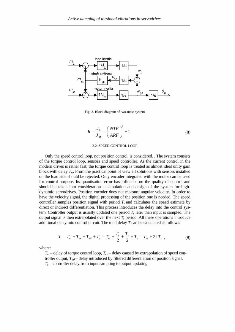
Active damping of torsional vibrations in servodrives_____________________________________________________________________
Fig 2 Block diagram of two-mass system
12
minus
ARF
NTF=
J
J=R
M
L (8)
22 SPEED CONTROL LOOP
Only the speed control loop not position control is considered The system consistsof the torque control loop sensors and speed controller As the current control in themodern drives is rather fast the torque control loop is treated as almost ideal unity gainblock with delay Tm From the practical point of view all solutions with sensors installedon the load side should be rejected Only encoder integrated with the motor can be usedfor control purpose Its quantisation error has influence on the quality of control andshould be taken into consideration at simulation and design of the system for high-dynamic servodrives Position encoder does not measure angular velocity In order tohave the velocity signal the digital processing of the position one is needed The speedcontroller samples position signal with period Ts and calculates the speed estimate bydirect or indirect differentiation This process introduces the delay into the control sys-tem Controller output is usually updated one period Ts later than input is sampled Theoutput signal is then extrapolated over the next Ts period All these operations introduceadditional delay into control circuit The total delay T can be calculated as follows
smsss
mcdθexm T+T=T+T
+T
+TT+T+T+T=T sdotasymp 222
(9)
whereTm ndash delay of torque control loop Tex ndash delay caused by extrapolation of speed con-troller output Tdθ ndash delay introduced by filtered differentiation of position signalTc ndash controller delay from input sampling to output updating
Active damping of torsional vibrations in servodrives_____________________________________________________________________
The general block diagram of the speed control loop is shown in Fig 3 The control-ler is modelled in the discrete-time domain while the rest of the loop in the continuous-time domain All delays due to digital processing are represented directly in the con-troller model Apart from the linear blocks represented by G(z) the diagram includestwo non-linear ones the quantiser of the position measurement signal θM and the limiterof the torque reference signal mrd All signals used in discrete-time domain are mark outby additional subscript d Such non-linear model has been used in simulation experi-ments However most of design methods for speed control base on linear and homoge-neous models (all-digital or all-continuous) In such models the both mentioned abovenon-linearities can be taken into consideration as factors limiting the range of possiblechoices of controller gains Non-linear quantisation block can be substituted by the in-dependent source of quantisation noise This noise amplified by the controller must notactivate output limiter at any working conditions In the all-continuous-time model de-lay caused by the position differentiation sampling and extrapolation should be repre-sented by additional delay block or included to the model of torque control loop
Fig 3 General block diagram of speed control loop
Additional input to the controller marked with dashed line is designated for testingpurposes The disturbing signal mdd can excite oscillating modes much more effectivelythan changes of load torque Moreover practical implementation of an internal torsionexcitation test is very simple as compared to a real one The setting time of the motorspeed ωM after step change of the mdd has been chosen as a measure of active dampingability of the speed controller
Active damping of torsional vibrations in servodrives_____________________________________________________________________
3 PI PID CONTROLLERS
31 TRANSFER FUNCTIONS OF IPD CONTROLLERS
Proportional-integral and proportional-integral-derivative controllers PI PID arethe simplest and the most commonly used Feedback transfer function (from θMd tomrd) of discrete-time PID speed controller can be expressed as follows
( )( ) ( ) ( )
zz
z
T
T+
z
z
T
T+K
zT
z=
zzCzH=
zθ
zm
s
d
i
sp
sMd
rd 11
11
11 sdot
minusminus
sdotminusminussdotsdotminus (10)
The first term H(z) is the transfer function of the first-order-differentiating filterwhich transforms the measured position signal θMd into the speed feedback signal ωMdThe medium term C(z) expresses the digital PID algorithm The last term 1z delaysthe controller output by one Ts period In case of PI controller the derivative time-constant Td is zero and one reduces the order of the controller
Reference transfer function (from ωrd to mrd) does not need to be exactly the samelike feedback transfer function C (z)z This additional degree of freedom gives op-portunity to independently shape the response to feedback signal and the response toreference signal The ability of active damping depends on the feedback transmit-tance only The reference transfer function of two-degree-of-freedom (2DOF) PIDcontroller can be arbitrarily chosen provided that the integral term is exactly the sameas in C(z) The simplest choice is to neglect all other terms
( )( ) ( )
zz
z
T
TK=
zzF=
zω
zm
i
sp
rd
rd 1
1
1 sdotminus
sdot (11)
Such controller sometimes called ldquoIPD controllerrdquo assures fast response to feed-back signal as well as soft reaction on step change of the speed reference signal Softreaction is desirable in order to avoid excitation of the torsional vibrations
Transfer functions C(z) and F(z) can be re-arranged and combined together inmany different ways Block diagram of the proposed unconventional IPD controller ispresented in Fig4 The output signal is the limited integral of the sum of components(P+D+D2) Therefore any separate anti-wind-up circuit is not necessary
Active damping of torsional vibrations in servodrives_____________________________________________________________________
Fig4 Block diagram of the proposed IPD controller
32 ACTIVE DAMPING WHEN DELAYS ARE NEGLIGIBLE
Speed control of two-inertia system by the PIPID controller was analysed in [21]using the pole placement method Delays were neglected ideal speed feedback wasassumed and the fourth-order continuous-time domain model represented the wholesystem An arbitrary placement of the poles of the closed speed control loop was notpossible for the flexible coupled drive However it was found that good dampingcould be obtained for limited range of drive parameters Three different methods ofchoosing pole location were proposed The method assuming equality of the real partsof both complex pole pairs seemed the most promising The damping coefficient ξ1for one pole pair could be chosen as design parameter while the second oneξ2 resulted from the mentioned equality The PI controller set up according to thismethod was able to damp vibration for the inertia ratio within the range of 1 lt R lt 4
Several analyses and simulations have been carried out to find the parameters of PIcontroller at which the shortest setting time is obtained for each value of inertia ratioR It has been found that the damping coefficient ξ1 of the slower pole pair should beset to the value higher than 08 for R gt 15 and to about 064 for R=1 The perform-ance of PI control in the range of 15ltRlt4 can be characterised by the followingfeatures
ndash Setting time is about 15 ARFndash Speed drop ∆ωmax after step change of the load torque mL is about 5middotARFmiddotmLKsh
The authors [21] proposed PID control if the inertia ratio R is greater than 4 or lessthan 1 The derivative action should virtually reduce the motor inertia JM to the newvalue JM at which the inertia ratio R is sufficient for PI control Controller gain Kp andtime-constant Ti can be calculated as previously provided JM (virtual inertia) is usedinstead of real value JM
Active damping of torsional vibrations in servodrives_____________________________________________________________________
33 ACTIVE DAMPING WHEN DELAY CONSIDERED
Numerous simulation experiments have been carried out in order to find the rangeof delay at which the PIPID controller set up according to previously describedrules could be used The results of this investigation are shown in Fig 5 and can besummarised as follows
ndash Delay TmiddotNTF not greater than 01 is acceptable for the inertia ratio in the range1ltRlt4 In that case the performance is only slightly degraded but the delay mar-gin is low Even the 15 increase in delay can be enough to make the system un-stable
ndash For the inertia ratio higher than 75 or lower than 05 even very small delaysTmiddotNTFlt005 can not be neglected
Fig 5 Active damping with controller parameters dependent only on R a) gain and time-constants
b) stability boundary as function of R and TmiddotNTF c) setting time for various delays TmiddotNTF
Active damping of torsional vibrations in servodrives_____________________________________________________________________
Fig 6 Active damping with controller parameters dependent on R and delay a) gain Kpb) integral time-constant Ti c) derivative time-constant TD
d) setting time after step change of virtual disturbance torque mdd
The aim of further work was to widen the range of admissible delays by changingthe controller parameters Considerable improvement has been achieved Optimal set-tings of Kp Ti Td shown in Fig 6 a b c as a function of both R and TmiddotNTF havebeen found by simulations experiment The characteristics of setting time shown inFig 6 d and can be summarised as follows
ndash Stable operation is possible in the wide investigated range of parameters025ltRlt8 0ltTmiddotNTFlt04
ndash For moderate delays (TmiddotNTFlt015) the performance is slightly better than previ-ously for no-delay conditions
ndash For higher values of total delay (TmiddotNTFgt015) the setting time can be considera-bly longer
Exemplary waveforms showing damping ability of the IPD controller set up ac-cording to Fig 5 and Fig 6 are presented in Fig7
Active damping of torsional vibrations in servodrives_____________________________________________________________________
4 STATE CONTROLLER WITH STATE OBSERVER
41 STRUCTURE OF THE SYSTEM
The state controller is one of the classical solutions of the control task It is oftenused also for the systems with flexibility [1] [2] [3] [12] and [20] According to as-sumption of this work many structures of the system with state controller intended forhigh power drives should be rejected because of additional sensors installed on the loadside The structure using only the position encoder integrated with the motor is shown inFig 8 There are elements of digital processing (sampler differentiation procedure) ofposition signal in the feedback path of the model They introduce to the path the delay Tf
equal to the time step Ts of the DSP controller Other blocks in the model are simulatedin continuous-time domain Their delays are included to the block modelling torquecontrol loop (total delay Tg of the block)
The state controller uses the signals of motor mM and shaft shm torque as well as
motor ωMd and load Lω speed The feedback from signal mM is easy to realise as themotor torque is usually proportional to the current (whose signal is measurable) In somecases the reference torque mr can be used instead of motor torque mM This solution cor-
responds to the controller shown in Fig 3 In order to have the signals shm and Lω thecontroller algorithm must realise also observer procedure In frame of presented on
Fig 8 controller it is also possible to test system without internal feedback signal shm or
Lω
Fig7 Waveforms of motor speed ωM and load speed ωL as responses on step change of reference
speed ωrd and following step change of signal mdd a) with controller set up according to [21] and
Fig5 a b) with proposed settings according to Fig 6 (R=2 TmiddotNTF=011)
Active damping of torsional vibrations in servodrives_____________________________________________________________________
z
11minus
sT
1 θMd
Differentiation Sampler
Quantiser
Digital processing delay Tf = Ts
Statecontroller
gsTeminus
2-masssystem(fig 2)
θM
mL
mM
Torque control loop inclu-ding additional delay
mr
Stateobserver
shm
Lω
ωMd
ωr
mM bull
bull
bull
Fig 8 Model of the system with state controller and state observer
42 THE STATE CONTROLLER
The linear state controller operates according to the equation
LLshshMdMMmrr ωkmkωkmkωkm minusminusminusminus= ω (12)
where the gains of component with reference motor and load speed should fulfil therelation
LM kkk +=ω (13)
in order to have no load operation without speed error Therefore if
ωkakM sdot= (14)
then
( ) ωkakL sdotminus= 1 (15)
Active damping of torsional vibrations in servodrives_____________________________________________________________________
where the a is the weight of the motor speed feedback and 1ndasha is the weight of the loadspeed feedback The coefficients kω a km and ksh are the parameters of the controllerinfluencing the properties of the system These parameters are selected using optimisa-tion procedure as described in subchapter 44
Instead of the linear state controller the non-linear one described in [16] can be usedIt should give further improving the properties also in the systems with delay
43 THE STATE OBSERVER
The observer (Fig 9) contains the two-mass model (Fig 2) and correction elements
Reduction of the error between the motor speed ωMd and speed Mω from the observer tothe value near by zero allows reproducing the signals of the load speed ωL and shafttorque msh A quality of it depends on the gains h1 h4 In order to reproduce the loadtorque mL the error of the observation of motor speed is integrated in the circuit with thegain h4
The signal Lm can be used in the observer for compensation of the speed drop due to
loading the drive For this purpose the signal Lm should be introduced to the torquesumming point (dashed line in the Fig 9) with positive gain hL The principle of thiscompensation is given in [10] together with derivation of the following condition
m
shL k
kh
++=
11 (16)
at which the speed is invariant with regard to loading
44 RESULTS OF THE PRELIMINARY SIMULATION
Preliminary the system from Fig 8 was simulated without the observer i eksh=kL=0 and a = 1 The inertia ratio was R = 1 During investigation the total delay Twas varied Every time the T was divided in two parts Tg = 2T3 and Tf = T3 Themaximum value of index TNTF was searched at which the controller is able active todamp the oscillations For each value of delay the gains kω and km of the controller wereoptimised The maximum ratio of two successive amplitudes of the oscillating quantitieswas the optimisation criterion
The results of the simulation are given in Table 1 It is seen that with increase ofstiffness (delay) the optimum value of feedback gains decrease Simultaneously the set-ting time becomes longer State controller having only motor speed and motor torque
Active damping of torsional vibrations in servodrives_____________________________________________________________________
Fig 9 The state observer
feedback paths is able to damp the oscillation in the system with stiffness up to about023 (the highest value in the Table 1)
A better result is expected after additionally feeding the controller from the observerwith the feedback signals of the shaft torque and load speed However the degree ofimprovement of system properties will depend strongly on encoder inaccuracy and alsoon delay as the observer uses non-actual values of the quantities
Table 1 The dependence of the controller parameters and setting time on thestiffness factor for the system with state controller having only two feedback paths
Stiffness factorTNTF 0101 0135 0169 0230
kω [Nsrad] 1 0556 0333 0133Controllerparameters km [-] 1 0667 0333 0167
Setting time multipliedby the ARF 113 163 424 very long
The controller parameters are relate to first data column
Active damping of torsional vibrations in servodrives_____________________________________________________________________
5 SLOW RESONANCE RATIO CONTROLLER
The slow resonance ratio control (SRRC) was firstly introduced as a method forvibration suppression and disturbance rejection in torsional systems [1] [6] [7]SRRC algorithm feeds back the torsional torque estimated by a model-based distur-bance observer so to change the virtual motor inertia to an arbitrary selected valueThis means that the resonance frequency NTF and then the resonance ratioH=NTFARF can be changed
Fig 2e-sT
JM
1-K
Differential
2DOF PI
LPF(Tq)LPF(Tq)
Differential
K+
++-
+-
digital speed controllerωrd
ωMd θMd
θM
mrd
mM
mL
mr
samplerquantizer
torque control loopand additional delay
2-mass systemextrapolator
msh^
Fig 10 Block diagram of resonance control
The detail of the resonance ratio control with shaft torque observer is reported inFig 10 where the mechanical model from Fig 2 has been used The digital speedcontrollerrsquos model has been simplified by fusion all delays in the closed loop torquecontrol Based on measurement motor speed ωMd and reference torque mrd the shaft
torque shm is estimated Only (1-K) portion of the estimated shaft torque is fed backBy doing this the designed virtual motor inertia JM-des is defined as
KJJ MdesM =minus (17)
This means that virtual inertia ratio Rdes can be expressed as
KRJJR LdesMdes sdot== minus (18)
Active damping of torsional vibrations in servodrives_____________________________________________________________________
The resonance ratio H could be changed to value desdes RH += 1
The slow disturbance observer was originally proposed by Iwata and Itoh [8]They proposed that the optimal cut-off frequency should be a little lower than theanti-resonant frequency ARF The optimal observer time constant Tq is calculated onbasis R and Rdes as given by [17]
ARFRRRR
RR
Tdesdes
des
q sdotsdot
++
++
++=
π21
21
43
1
4
31
When PI speed controller is used the characteristic equation of the closed drive sys-tem is
01
12
23
34
4)( asasasasasP ++++= (19)
The coefficients a4ndasha0 can be selected according to desired dynamical propertiesof whole system The effective method is Coefficient Diagram Method based on Ma-nabe polynomials [15] In this method design specifications are equivalent time con-stant (τ ) and stability indices (γi) For analysed system τ is defined as
01 aa=τ (20)
and stability indices should be selected as follow
2 2 5242
23
331
22
220
21
1 ======aa
a
aa
a
aa
a γγγ (21)
By solving these equations the optimal resonance ratio can be determined
580 sdot=desH This correspond to inertia ratio Rdes=115
From (18) the coefficient K is calculated The controller gains are given by (com-pare [7])
22
)(11
1611
220
ARFJK
ARFJK
Li
Lp
sdotsdotsdot=
sdotsdotsdot=
π
π
(22)
Active damping of torsional vibrations in servodrives_____________________________________________________________________
Simulation experiments has been carried out to find the range of stabile parameters atwhich presented SRRC could be used The results of this investigation can be summa-rised as followsStability boundary
- TmiddotNTF gt 012 for 08 lt R lt 2- TmiddotNTF gt 010 for 08 lt R lt 8- TmiddotNTF gt 003 for 035 lt R lt 8
Setting time Tω - ARF Tω lt18 for TmiddotNTF = 01 and 08 lt R lt 2- ARF Tω lt42 for TmiddotNTF = 008 and 2 lt R lt 8- ARF Tω lt51 for TmiddotNTF = 006 and 05 lt R lt 1
Presented slow resonance ratio controller is well fitting for system with relativelarge load inertia in relation to motor inertia In such case the virtual motor inertia isincreasing through using feedback coefficient K smaller than 1 and the whole systemis robust to real-time delays However if the load inertia is small feedback coeffi-cient K greater than 1 is needed and system is sensitive to any time lags It should benoted that when the motor inertia is much larger than the load inertia the resonanceratio control makes the disturbance response worse This fact suggests that the vibra-tion suppression and the disturbance rejection are opposite objectives [7]
6 LINEAR-QUADRATIC CONTROLLER WITH KALMAN FILTER
61 STATE AND DISTURBANCES OBSERVER
When using the LQ-controller state vector should be available State variables thatcannot be measured should be estimated
The Kalman Filter is one of proposed estimators [11] [12] [13] [17] Kalmanfilter theory allows estimating all state variables Theory presented in [11] determinesthe state variables They could be disturbed by Gaussian white noise which repre-sents all error sources and model inaccuracy [11] This is a narrow assumption thathas been avoided in his work This causes difficulties with theoretical tuning rules
Basing on filtering knowledge [11] the model of the system can be expressed bystate (23) and measurement (24) equations
1n e n e n nx x u w+ = + +A B (23)
n e n ny x v= +C (24)
Active damping of torsional vibrations in servodrives_____________________________________________________________________
where the control signal u is equal to the torque command mr and the output vector yis equal to mechanical position θ In equations (23) and (24) w represents a processnoise and v - measurement noise
It is assumed that the disturbing load torque (mL) is a part of measurement noiseand a part of state vector The assumption is only valid when the derivative of loadtorque is near to zero
0L
dm
dtasymp (25)
The state vector of observer has been extended by new estimated variable (Lm )
ˆˆ ˆˆ ˆ ˆT
M L sh Lx m mω ω θ = (26)
New state space matrices are equal
10 0 0 0
1 10 0 0
0 0 0
0 0 0 0 0
1 0 0 0 0
M
L Le
sh sh
J
J J
K K
minus minus =
minus
A
=
0
0
0
0
1
M
e
J
B
0
0
0
0
1
e
=
C (272829)
The equations of estimator are given by
( )| | 1 | 1
1| |
ˆ ˆ ˆ
ˆ ˆ ˆ
n n n n e n e n n
n n e n n e n
x x y x
x x u
minus minus
+
= + minus
= +
K C
A B (30)
where Ke is a Kalman filter gains which is computed by solving Ricatti equation[11] The gains can be calculated using recursive algorithm only one time and can bevalid for each step of control algorithm The noisersquos covariance of presented system(025ltRlt8 Ksh=1 equivalent of 14bit encoder) can be determine by matrix Qe
Active damping of torsional vibrations in servodrives_____________________________________________________________________
22
14
202 02 10 10
2e diag π =
Q (31)
which values represent covariances respectively with vector x elements The noisersquoscovariance of output signal may be described by
2
e 14
2
2R
π =
(32)
Theoretically the appropriate values should be real covariance but they was se-lected experimentally during system investigations It is noticed that last element ofQe matrix and Re is linked with the one known error It is caused by the quantisationduring obtaining real position from the 14-bit encoder
62 LQ CONTROL STRATEGY
The LQ-controller has several good properties [4] [9] and [18] It is applicable tomultivariable and time-varying systems when a model of the system can be availablein state space form (Fig 11) Changing the relations between the magnitude of ele-ments in weighting matrices we obtain compromise between the control speed and themagnitudes of control signals
Fig 11 Model of the system with LQ-controller and Kalman filter
The finding of answer presented in [9] is applicable to our system The generalformulation of the problem is to minimise the performance index J The following
Active damping of torsional vibrations in servodrives_____________________________________________________________________
deviations from steady state has been defined ∆x ∆u (for state and control variablesrespectively) The designed problem was reformulated to LQ-compensator with newdefined performance index J
( ) ( )( )2
0
T
r rJ R ux xinfin
= + ∆∆ ∆int Q (33)
where Qr and Rr are defined tuning matricesIn state controller the control-input signal is given by follows
r
xu
p
= minus
K (34)
Partitioning Kr and using integral control to cancel steady-state error
( )0
ˆt
M rdp dtω ω= minusint (35)
the control input signal yields
[ ] ( )1 2 3
0
ˆ
ˆ ˆ
ˆ
M t
L p M rd
sh
u K K K K dt
m
ωω ω ω = minus minus minus
int (36)
The main problem during solving LQ regulator is proper choosing the performanceindex J As shown in [9] Qr and Rr are given as
0 0
0 0
0 0 0 0
0 0 0
r
α αα α β
δ
minus minus + =
Q rR ε= (3738)
Performance index (33) can be expressed in more practical form
Active damping of torsional vibrations in servodrives_____________________________________________________________________
( ) ( )( ) ( )
2 2
2 20
M L L Ls
s s
J dtp p u u
α ω ω β ω ω
δ ε
infin minus + minus + = + minus + minus
int (39)
where Greek symbols mark weighting for α ndash torsional vibration suppression
β ndash command following δ ndash steady-state error ε ndash control input
The weight factors were selected experimentally α = 1 β = 100 δ = 100 ε = 01
63 SIMULATION RESULTS
Simulation experiments confirmed that there exists a range of delay at which theLQ-controller using signals dealt by Kalman filter can be constructed The wholesystem has been experimentally tuned (without any optimisation) to check how thetotal delay T influences system performance The preliminary results of investigationcan be briefly formulated as follows
ndash Delay TsdotNTF lt 008 has very small influence on system performance
ndash The setting time without delay is ARFsdotTω asymp 2 Similar performance can be ob-
tained for increasing delay only in limited range of inertia ratio
ndash TsdotNTF lt 008 and 025ltRlt05
ndash TsdotNTF lt 011 and R=1
ndash TsdotNTF lt 02 and 2 lt R lt 8
ndash When TsdotNTF lt 035 the system is stable but the setting time is unacceptable
large
7 CONCLUSION
It is possible to actively damp torsional vibration using single feedback signal fromencoder only Damping ability depends on the inertia ratio R and total delay T in thespeed control loop Because single feedback signal is considered and the controllerhas single output all analysed controllers can be treated as digital filters Apart fromvarious internal descriptions all controllers actually differ only in filter order and co-efficients Methods of calculation and tuning controller gains (or filter coefficients)are also different Unfortunately no systematic design methods have been found forthe analysed controllers Only heuristic approach for controller tuning was tested Themost complete and most promising results have been obtained for the unconventional
Active damping of torsional vibrations in servodrives_____________________________________________________________________
IPD controllers The near-optimum parameters have been found by simulation ex-periments for wide range of R and T These parameters can be directly applied in realPID controlled industrial drives
Another considered methods have been elaborated only partially Because theyconstitute filters of higher order than simple PI-controller probably better resultscould be obtained This possible advantage has not been fully confirmed in this workAuthors concentrate on practical rules for choosing suitable parameters of state con-troller and observer as well as gains of Kalman filter and LQ compensator
ACKONWLEDGEMENT
This work was partially supported by the grant 3 T10A 026 28
REFERENCES
[1] BOLOGNANI S VENTURATO A ZIGLIOTTO M Theoretical and experimental comparisonof speed controllers for elastic two-mass-systems Proc31st APESCrsquo2000 vol 3 pp1087-10922000
[2] DEUR J PERIC N Analysis of speed control system for electrical drives with elastic transmissionProc of the IEEE Int Symp ISIErsquo99 Bled Slovenia vol 2 pp 624-630 1999
[3] DEUR J PERIC N Pointing and tracking position control system for electrical drives with elastictransmission Proc 9th Int Conf PEMCrsquo2000 Kosice Slovak Republic pp7-1-7-6 2000
[4] FRANKLIN GF POWELL JD WORKMAN ML Digital Control of Dynamic Systems 3rdEdition Prentice Hall 1997
[5] GIERLOTKA K ZALEŚNY P Metoda obliczania parametroacutew układu regulacji napędu z połą-czeniem spręŜystym z dodatkowymi sprzęŜeniami zwrotnymi ZN Politechniki Śląskiej Elektrykaz170 (1999) str 65-72
[6] HORI Y SAWADA H CHUN Y Slow Resonance Ratio Control for Vibration Suppression andDisturbance Rejection in Torsional System IEEE Trans on Industrial Electronics vol 34 pp 162-168 1999
[7] HORI Y Comparison of Torsional Vibration Controls based on the Fast and Slow DisturbanceObservers Proc Int Conf IPEC95 Vol1 pp440-446 Yokohama 1995
[8] IWATA M ITOH S High Performance and Adaptive Motion Control System Based on IdentifiedMechanical Parameter Proc 3rd Int Workshop on Advanced Motion Control 1994 Berkeley
[9] JI J-K SUL S-K Kalman filter and LQ based speed controller for torsional vibration suppres-sion in a 2-mass motor drive system IEEE Trans Ind Electron vol 42 no 6 pp564ndash571 1995
[10] KALEJTA T MUSZYŃSKI R State observer for servodrive with flexibility Proc 4th Int SympELECTROMOTION`01 Bologna Italy vol 1 pp 159-164 2001
[11] KALMAN RE New Approach to Linear Filtering and Prediction Problems Trans of the ASMEJournal of Basic Engineering 1960 pp 374-382
[12] ORŁOWSKA-KOWALSKA T SZABAT K Zastosowanie regulatora stanu w układzie napędo-wym z połączeniem spręŜystym MaterVI Kraj Konf SENE 2003 tom III pp 679-685
[13] ORŁOWSKA-KOWALSKA T SZABAT K State Feedback Control of Two-Mass System withState Estimator Proc Int ConfEDPErsquo2003 Hihg Tatras Slovak Rep pp 590-595 2003
[14] ORŁOWSKA-KOWALSKA T SZABAT K Optimization of fuzzy-logic speed controller for DC
Active damping of torsional vibrations in servodrives_____________________________________________________________________
drive system with elastic joints IEEE Trans on Ind Applic vol 40 no 4 pp1138-1144 2004[15] MANABE S Coefficient Diagram Method Proc 14th IFAC Symp on Automatic Control in Aero-
space Seoul1998[16] MUSZYŃSKI R KACZMAREK T The elastic servo drive with state controller Archives of
Electrical Engineering vol LII no 2 pp 185-200 2003[17] SHIN D-J HUH U-Y Robust motion controller design for servo system with 2 mass characteris-
tics Proc 6th Inter Workshop on Advanced Motion Control 2000 pp 423-426[18] STEFANI R SAVANT C SHAHIAN B HOSTETTER G Design of Feedback Control Systems
Saunders College Publisher 1994[19] SZABAT K ORŁOWSKA-KOWALSKA T Tłumienie oscylacji prędkości w układzie napędowym
z połaczeniem spręŜystym Przegląd Elektrotechniczny vol LXXIX no 7-8 pp 474-482 2003[20] ШИЯНОВ А И МЕДВЕДЕВ ΒАМОРОЗОВ СВ Асинхронный злектропривод с упругой
нагрузкой и адаптивным регулятором ЗЛЕКТРИЧЕСТВО no 2 pp47divide49 2001[21] ZHANG G FURUSHO J Speed Control of Two-Inertia System by PIPID control IEEE Trans on
Industrial Electronics vol 47 no3 pp 603-609 2000
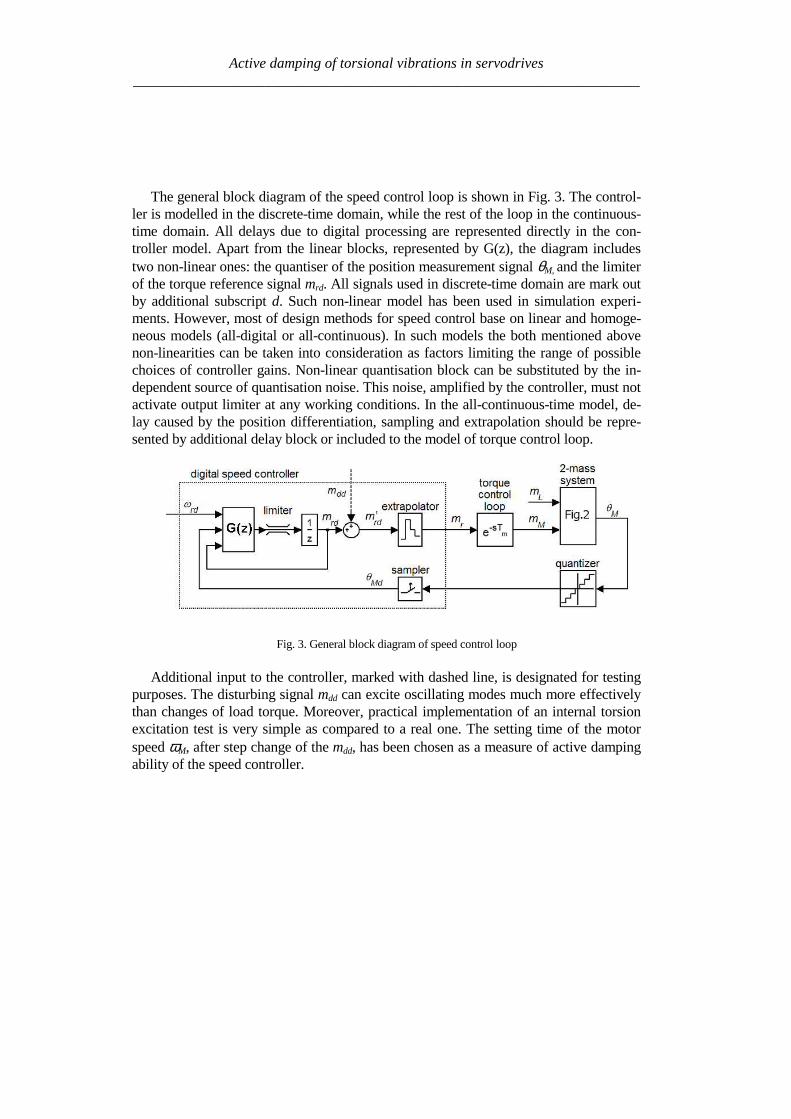
Active damping of torsional vibrations in servodrives_____________________________________________________________________
The general block diagram of the speed control loop is shown in Fig 3 The control-ler is modelled in the discrete-time domain while the rest of the loop in the continuous-time domain All delays due to digital processing are represented directly in the con-troller model Apart from the linear blocks represented by G(z) the diagram includestwo non-linear ones the quantiser of the position measurement signal θM and the limiterof the torque reference signal mrd All signals used in discrete-time domain are mark outby additional subscript d Such non-linear model has been used in simulation experi-ments However most of design methods for speed control base on linear and homoge-neous models (all-digital or all-continuous) In such models the both mentioned abovenon-linearities can be taken into consideration as factors limiting the range of possiblechoices of controller gains Non-linear quantisation block can be substituted by the in-dependent source of quantisation noise This noise amplified by the controller must notactivate output limiter at any working conditions In the all-continuous-time model de-lay caused by the position differentiation sampling and extrapolation should be repre-sented by additional delay block or included to the model of torque control loop
Fig 3 General block diagram of speed control loop
Additional input to the controller marked with dashed line is designated for testingpurposes The disturbing signal mdd can excite oscillating modes much more effectivelythan changes of load torque Moreover practical implementation of an internal torsionexcitation test is very simple as compared to a real one The setting time of the motorspeed ωM after step change of the mdd has been chosen as a measure of active dampingability of the speed controller
Active damping of torsional vibrations in servodrives_____________________________________________________________________
3 PI PID CONTROLLERS
31 TRANSFER FUNCTIONS OF IPD CONTROLLERS
Proportional-integral and proportional-integral-derivative controllers PI PID arethe simplest and the most commonly used Feedback transfer function (from θMd tomrd) of discrete-time PID speed controller can be expressed as follows
( )( ) ( ) ( )
zz
z
T
T+
z
z
T
T+K
zT
z=
zzCzH=
zθ
zm
s
d
i
sp
sMd
rd 11
11
11 sdot
minusminus
sdotminusminussdotsdotminus (10)
The first term H(z) is the transfer function of the first-order-differentiating filterwhich transforms the measured position signal θMd into the speed feedback signal ωMdThe medium term C(z) expresses the digital PID algorithm The last term 1z delaysthe controller output by one Ts period In case of PI controller the derivative time-constant Td is zero and one reduces the order of the controller
Reference transfer function (from ωrd to mrd) does not need to be exactly the samelike feedback transfer function C (z)z This additional degree of freedom gives op-portunity to independently shape the response to feedback signal and the response toreference signal The ability of active damping depends on the feedback transmit-tance only The reference transfer function of two-degree-of-freedom (2DOF) PIDcontroller can be arbitrarily chosen provided that the integral term is exactly the sameas in C(z) The simplest choice is to neglect all other terms
( )( ) ( )
zz
z
T
TK=
zzF=
zω
zm
i
sp
rd
rd 1
1
1 sdotminus
sdot (11)
Such controller sometimes called ldquoIPD controllerrdquo assures fast response to feed-back signal as well as soft reaction on step change of the speed reference signal Softreaction is desirable in order to avoid excitation of the torsional vibrations
Transfer functions C(z) and F(z) can be re-arranged and combined together inmany different ways Block diagram of the proposed unconventional IPD controller ispresented in Fig4 The output signal is the limited integral of the sum of components(P+D+D2) Therefore any separate anti-wind-up circuit is not necessary
Active damping of torsional vibrations in servodrives_____________________________________________________________________
Fig4 Block diagram of the proposed IPD controller
32 ACTIVE DAMPING WHEN DELAYS ARE NEGLIGIBLE
Speed control of two-inertia system by the PIPID controller was analysed in [21]using the pole placement method Delays were neglected ideal speed feedback wasassumed and the fourth-order continuous-time domain model represented the wholesystem An arbitrary placement of the poles of the closed speed control loop was notpossible for the flexible coupled drive However it was found that good dampingcould be obtained for limited range of drive parameters Three different methods ofchoosing pole location were proposed The method assuming equality of the real partsof both complex pole pairs seemed the most promising The damping coefficient ξ1for one pole pair could be chosen as design parameter while the second oneξ2 resulted from the mentioned equality The PI controller set up according to thismethod was able to damp vibration for the inertia ratio within the range of 1 lt R lt 4
Several analyses and simulations have been carried out to find the parameters of PIcontroller at which the shortest setting time is obtained for each value of inertia ratioR It has been found that the damping coefficient ξ1 of the slower pole pair should beset to the value higher than 08 for R gt 15 and to about 064 for R=1 The perform-ance of PI control in the range of 15ltRlt4 can be characterised by the followingfeatures
ndash Setting time is about 15 ARFndash Speed drop ∆ωmax after step change of the load torque mL is about 5middotARFmiddotmLKsh
The authors [21] proposed PID control if the inertia ratio R is greater than 4 or lessthan 1 The derivative action should virtually reduce the motor inertia JM to the newvalue JM at which the inertia ratio R is sufficient for PI control Controller gain Kp andtime-constant Ti can be calculated as previously provided JM (virtual inertia) is usedinstead of real value JM
Active damping of torsional vibrations in servodrives_____________________________________________________________________
33 ACTIVE DAMPING WHEN DELAY CONSIDERED
Numerous simulation experiments have been carried out in order to find the rangeof delay at which the PIPID controller set up according to previously describedrules could be used The results of this investigation are shown in Fig 5 and can besummarised as follows
ndash Delay TmiddotNTF not greater than 01 is acceptable for the inertia ratio in the range1ltRlt4 In that case the performance is only slightly degraded but the delay mar-gin is low Even the 15 increase in delay can be enough to make the system un-stable
ndash For the inertia ratio higher than 75 or lower than 05 even very small delaysTmiddotNTFlt005 can not be neglected
Fig 5 Active damping with controller parameters dependent only on R a) gain and time-constants
b) stability boundary as function of R and TmiddotNTF c) setting time for various delays TmiddotNTF
Active damping of torsional vibrations in servodrives_____________________________________________________________________
Fig 6 Active damping with controller parameters dependent on R and delay a) gain Kpb) integral time-constant Ti c) derivative time-constant TD
d) setting time after step change of virtual disturbance torque mdd
The aim of further work was to widen the range of admissible delays by changingthe controller parameters Considerable improvement has been achieved Optimal set-tings of Kp Ti Td shown in Fig 6 a b c as a function of both R and TmiddotNTF havebeen found by simulations experiment The characteristics of setting time shown inFig 6 d and can be summarised as follows
ndash Stable operation is possible in the wide investigated range of parameters025ltRlt8 0ltTmiddotNTFlt04
ndash For moderate delays (TmiddotNTFlt015) the performance is slightly better than previ-ously for no-delay conditions
ndash For higher values of total delay (TmiddotNTFgt015) the setting time can be considera-bly longer
Exemplary waveforms showing damping ability of the IPD controller set up ac-cording to Fig 5 and Fig 6 are presented in Fig7
Active damping of torsional vibrations in servodrives_____________________________________________________________________
4 STATE CONTROLLER WITH STATE OBSERVER
41 STRUCTURE OF THE SYSTEM
The state controller is one of the classical solutions of the control task It is oftenused also for the systems with flexibility [1] [2] [3] [12] and [20] According to as-sumption of this work many structures of the system with state controller intended forhigh power drives should be rejected because of additional sensors installed on the loadside The structure using only the position encoder integrated with the motor is shown inFig 8 There are elements of digital processing (sampler differentiation procedure) ofposition signal in the feedback path of the model They introduce to the path the delay Tf
equal to the time step Ts of the DSP controller Other blocks in the model are simulatedin continuous-time domain Their delays are included to the block modelling torquecontrol loop (total delay Tg of the block)
The state controller uses the signals of motor mM and shaft shm torque as well as
motor ωMd and load Lω speed The feedback from signal mM is easy to realise as themotor torque is usually proportional to the current (whose signal is measurable) In somecases the reference torque mr can be used instead of motor torque mM This solution cor-
responds to the controller shown in Fig 3 In order to have the signals shm and Lω thecontroller algorithm must realise also observer procedure In frame of presented on
Fig 8 controller it is also possible to test system without internal feedback signal shm or
Lω
Fig7 Waveforms of motor speed ωM and load speed ωL as responses on step change of reference
speed ωrd and following step change of signal mdd a) with controller set up according to [21] and
Fig5 a b) with proposed settings according to Fig 6 (R=2 TmiddotNTF=011)
Active damping of torsional vibrations in servodrives_____________________________________________________________________
z
11minus
sT
1 θMd
Differentiation Sampler
Quantiser
Digital processing delay Tf = Ts
Statecontroller
gsTeminus
2-masssystem(fig 2)
θM
mL
mM
Torque control loop inclu-ding additional delay
mr
Stateobserver
shm
Lω
ωMd
ωr
mM bull
bull
bull
Fig 8 Model of the system with state controller and state observer
42 THE STATE CONTROLLER
The linear state controller operates according to the equation
LLshshMdMMmrr ωkmkωkmkωkm minusminusminusminus= ω (12)
where the gains of component with reference motor and load speed should fulfil therelation
LM kkk +=ω (13)
in order to have no load operation without speed error Therefore if
ωkakM sdot= (14)
then
( ) ωkakL sdotminus= 1 (15)
Active damping of torsional vibrations in servodrives_____________________________________________________________________
where the a is the weight of the motor speed feedback and 1ndasha is the weight of the loadspeed feedback The coefficients kω a km and ksh are the parameters of the controllerinfluencing the properties of the system These parameters are selected using optimisa-tion procedure as described in subchapter 44
Instead of the linear state controller the non-linear one described in [16] can be usedIt should give further improving the properties also in the systems with delay
43 THE STATE OBSERVER
The observer (Fig 9) contains the two-mass model (Fig 2) and correction elements
Reduction of the error between the motor speed ωMd and speed Mω from the observer tothe value near by zero allows reproducing the signals of the load speed ωL and shafttorque msh A quality of it depends on the gains h1 h4 In order to reproduce the loadtorque mL the error of the observation of motor speed is integrated in the circuit with thegain h4
The signal Lm can be used in the observer for compensation of the speed drop due to
loading the drive For this purpose the signal Lm should be introduced to the torquesumming point (dashed line in the Fig 9) with positive gain hL The principle of thiscompensation is given in [10] together with derivation of the following condition
m
shL k
kh
++=
11 (16)
at which the speed is invariant with regard to loading
44 RESULTS OF THE PRELIMINARY SIMULATION
Preliminary the system from Fig 8 was simulated without the observer i eksh=kL=0 and a = 1 The inertia ratio was R = 1 During investigation the total delay Twas varied Every time the T was divided in two parts Tg = 2T3 and Tf = T3 Themaximum value of index TNTF was searched at which the controller is able active todamp the oscillations For each value of delay the gains kω and km of the controller wereoptimised The maximum ratio of two successive amplitudes of the oscillating quantitieswas the optimisation criterion
The results of the simulation are given in Table 1 It is seen that with increase ofstiffness (delay) the optimum value of feedback gains decrease Simultaneously the set-ting time becomes longer State controller having only motor speed and motor torque
Active damping of torsional vibrations in servodrives_____________________________________________________________________
Fig 9 The state observer
feedback paths is able to damp the oscillation in the system with stiffness up to about023 (the highest value in the Table 1)
A better result is expected after additionally feeding the controller from the observerwith the feedback signals of the shaft torque and load speed However the degree ofimprovement of system properties will depend strongly on encoder inaccuracy and alsoon delay as the observer uses non-actual values of the quantities
Table 1 The dependence of the controller parameters and setting time on thestiffness factor for the system with state controller having only two feedback paths
Stiffness factorTNTF 0101 0135 0169 0230
kω [Nsrad] 1 0556 0333 0133Controllerparameters km [-] 1 0667 0333 0167
Setting time multipliedby the ARF 113 163 424 very long
The controller parameters are relate to first data column
Active damping of torsional vibrations in servodrives_____________________________________________________________________
5 SLOW RESONANCE RATIO CONTROLLER
The slow resonance ratio control (SRRC) was firstly introduced as a method forvibration suppression and disturbance rejection in torsional systems [1] [6] [7]SRRC algorithm feeds back the torsional torque estimated by a model-based distur-bance observer so to change the virtual motor inertia to an arbitrary selected valueThis means that the resonance frequency NTF and then the resonance ratioH=NTFARF can be changed
Fig 2e-sT
JM
1-K
Differential
2DOF PI
LPF(Tq)LPF(Tq)
Differential
K+
++-
+-
digital speed controllerωrd
ωMd θMd
θM
mrd
mM
mL
mr
samplerquantizer
torque control loopand additional delay
2-mass systemextrapolator
msh^
Fig 10 Block diagram of resonance control
The detail of the resonance ratio control with shaft torque observer is reported inFig 10 where the mechanical model from Fig 2 has been used The digital speedcontrollerrsquos model has been simplified by fusion all delays in the closed loop torquecontrol Based on measurement motor speed ωMd and reference torque mrd the shaft
torque shm is estimated Only (1-K) portion of the estimated shaft torque is fed backBy doing this the designed virtual motor inertia JM-des is defined as
KJJ MdesM =minus (17)
This means that virtual inertia ratio Rdes can be expressed as
KRJJR LdesMdes sdot== minus (18)
Active damping of torsional vibrations in servodrives_____________________________________________________________________
The resonance ratio H could be changed to value desdes RH += 1
The slow disturbance observer was originally proposed by Iwata and Itoh [8]They proposed that the optimal cut-off frequency should be a little lower than theanti-resonant frequency ARF The optimal observer time constant Tq is calculated onbasis R and Rdes as given by [17]
ARFRRRR
RR
Tdesdes
des
q sdotsdot
++
++
++=
π21
21
43
1
4
31
When PI speed controller is used the characteristic equation of the closed drive sys-tem is
01
12
23
34
4)( asasasasasP ++++= (19)
The coefficients a4ndasha0 can be selected according to desired dynamical propertiesof whole system The effective method is Coefficient Diagram Method based on Ma-nabe polynomials [15] In this method design specifications are equivalent time con-stant (τ ) and stability indices (γi) For analysed system τ is defined as
01 aa=τ (20)
and stability indices should be selected as follow
2 2 5242
23
331
22
220
21
1 ======aa
a
aa
a
aa
a γγγ (21)
By solving these equations the optimal resonance ratio can be determined
580 sdot=desH This correspond to inertia ratio Rdes=115
From (18) the coefficient K is calculated The controller gains are given by (com-pare [7])
22
)(11
1611
220
ARFJK
ARFJK
Li
Lp
sdotsdotsdot=
sdotsdotsdot=
π
π
(22)
Active damping of torsional vibrations in servodrives_____________________________________________________________________
Simulation experiments has been carried out to find the range of stabile parameters atwhich presented SRRC could be used The results of this investigation can be summa-rised as followsStability boundary
- TmiddotNTF gt 012 for 08 lt R lt 2- TmiddotNTF gt 010 for 08 lt R lt 8- TmiddotNTF gt 003 for 035 lt R lt 8
Setting time Tω - ARF Tω lt18 for TmiddotNTF = 01 and 08 lt R lt 2- ARF Tω lt42 for TmiddotNTF = 008 and 2 lt R lt 8- ARF Tω lt51 for TmiddotNTF = 006 and 05 lt R lt 1
Presented slow resonance ratio controller is well fitting for system with relativelarge load inertia in relation to motor inertia In such case the virtual motor inertia isincreasing through using feedback coefficient K smaller than 1 and the whole systemis robust to real-time delays However if the load inertia is small feedback coeffi-cient K greater than 1 is needed and system is sensitive to any time lags It should benoted that when the motor inertia is much larger than the load inertia the resonanceratio control makes the disturbance response worse This fact suggests that the vibra-tion suppression and the disturbance rejection are opposite objectives [7]
6 LINEAR-QUADRATIC CONTROLLER WITH KALMAN FILTER
61 STATE AND DISTURBANCES OBSERVER
When using the LQ-controller state vector should be available State variables thatcannot be measured should be estimated
The Kalman Filter is one of proposed estimators [11] [12] [13] [17] Kalmanfilter theory allows estimating all state variables Theory presented in [11] determinesthe state variables They could be disturbed by Gaussian white noise which repre-sents all error sources and model inaccuracy [11] This is a narrow assumption thathas been avoided in his work This causes difficulties with theoretical tuning rules
Basing on filtering knowledge [11] the model of the system can be expressed bystate (23) and measurement (24) equations
1n e n e n nx x u w+ = + +A B (23)
n e n ny x v= +C (24)
Active damping of torsional vibrations in servodrives_____________________________________________________________________
where the control signal u is equal to the torque command mr and the output vector yis equal to mechanical position θ In equations (23) and (24) w represents a processnoise and v - measurement noise
It is assumed that the disturbing load torque (mL) is a part of measurement noiseand a part of state vector The assumption is only valid when the derivative of loadtorque is near to zero
0L
dm
dtasymp (25)
The state vector of observer has been extended by new estimated variable (Lm )
ˆˆ ˆˆ ˆ ˆT
M L sh Lx m mω ω θ = (26)
New state space matrices are equal
10 0 0 0
1 10 0 0
0 0 0
0 0 0 0 0
1 0 0 0 0
M
L Le
sh sh
J
J J
K K
minus minus =
minus
A
=
0
0
0
0
1
M
e
J
B
0
0
0
0
1
e
=
C (272829)
The equations of estimator are given by
( )| | 1 | 1
1| |
ˆ ˆ ˆ
ˆ ˆ ˆ
n n n n e n e n n
n n e n n e n
x x y x
x x u
minus minus
+
= + minus
= +
K C
A B (30)
where Ke is a Kalman filter gains which is computed by solving Ricatti equation[11] The gains can be calculated using recursive algorithm only one time and can bevalid for each step of control algorithm The noisersquos covariance of presented system(025ltRlt8 Ksh=1 equivalent of 14bit encoder) can be determine by matrix Qe
Active damping of torsional vibrations in servodrives_____________________________________________________________________
22
14
202 02 10 10
2e diag π =
Q (31)
which values represent covariances respectively with vector x elements The noisersquoscovariance of output signal may be described by
2
e 14
2
2R
π =
(32)
Theoretically the appropriate values should be real covariance but they was se-lected experimentally during system investigations It is noticed that last element ofQe matrix and Re is linked with the one known error It is caused by the quantisationduring obtaining real position from the 14-bit encoder
62 LQ CONTROL STRATEGY
The LQ-controller has several good properties [4] [9] and [18] It is applicable tomultivariable and time-varying systems when a model of the system can be availablein state space form (Fig 11) Changing the relations between the magnitude of ele-ments in weighting matrices we obtain compromise between the control speed and themagnitudes of control signals
Fig 11 Model of the system with LQ-controller and Kalman filter
The finding of answer presented in [9] is applicable to our system The generalformulation of the problem is to minimise the performance index J The following
Active damping of torsional vibrations in servodrives_____________________________________________________________________
deviations from steady state has been defined ∆x ∆u (for state and control variablesrespectively) The designed problem was reformulated to LQ-compensator with newdefined performance index J
( ) ( )( )2
0
T
r rJ R ux xinfin
= + ∆∆ ∆int Q (33)
where Qr and Rr are defined tuning matricesIn state controller the control-input signal is given by follows
r
xu
p
= minus
K (34)
Partitioning Kr and using integral control to cancel steady-state error
( )0
ˆt
M rdp dtω ω= minusint (35)
the control input signal yields
[ ] ( )1 2 3
0
ˆ
ˆ ˆ
ˆ
M t
L p M rd
sh
u K K K K dt
m
ωω ω ω = minus minus minus
int (36)
The main problem during solving LQ regulator is proper choosing the performanceindex J As shown in [9] Qr and Rr are given as
0 0
0 0
0 0 0 0
0 0 0
r
α αα α β
δ
minus minus + =
Q rR ε= (3738)
Performance index (33) can be expressed in more practical form
Active damping of torsional vibrations in servodrives_____________________________________________________________________
( ) ( )( ) ( )
2 2
2 20
M L L Ls
s s
J dtp p u u
α ω ω β ω ω
δ ε
infin minus + minus + = + minus + minus
int (39)
where Greek symbols mark weighting for α ndash torsional vibration suppression
β ndash command following δ ndash steady-state error ε ndash control input
The weight factors were selected experimentally α = 1 β = 100 δ = 100 ε = 01
63 SIMULATION RESULTS
Simulation experiments confirmed that there exists a range of delay at which theLQ-controller using signals dealt by Kalman filter can be constructed The wholesystem has been experimentally tuned (without any optimisation) to check how thetotal delay T influences system performance The preliminary results of investigationcan be briefly formulated as follows
ndash Delay TsdotNTF lt 008 has very small influence on system performance
ndash The setting time without delay is ARFsdotTω asymp 2 Similar performance can be ob-
tained for increasing delay only in limited range of inertia ratio
ndash TsdotNTF lt 008 and 025ltRlt05
ndash TsdotNTF lt 011 and R=1
ndash TsdotNTF lt 02 and 2 lt R lt 8
ndash When TsdotNTF lt 035 the system is stable but the setting time is unacceptable
large
7 CONCLUSION
It is possible to actively damp torsional vibration using single feedback signal fromencoder only Damping ability depends on the inertia ratio R and total delay T in thespeed control loop Because single feedback signal is considered and the controllerhas single output all analysed controllers can be treated as digital filters Apart fromvarious internal descriptions all controllers actually differ only in filter order and co-efficients Methods of calculation and tuning controller gains (or filter coefficients)are also different Unfortunately no systematic design methods have been found forthe analysed controllers Only heuristic approach for controller tuning was tested Themost complete and most promising results have been obtained for the unconventional
Active damping of torsional vibrations in servodrives_____________________________________________________________________
IPD controllers The near-optimum parameters have been found by simulation ex-periments for wide range of R and T These parameters can be directly applied in realPID controlled industrial drives
Another considered methods have been elaborated only partially Because theyconstitute filters of higher order than simple PI-controller probably better resultscould be obtained This possible advantage has not been fully confirmed in this workAuthors concentrate on practical rules for choosing suitable parameters of state con-troller and observer as well as gains of Kalman filter and LQ compensator
ACKONWLEDGEMENT
This work was partially supported by the grant 3 T10A 026 28
REFERENCES
[1] BOLOGNANI S VENTURATO A ZIGLIOTTO M Theoretical and experimental comparisonof speed controllers for elastic two-mass-systems Proc31st APESCrsquo2000 vol 3 pp1087-10922000
[2] DEUR J PERIC N Analysis of speed control system for electrical drives with elastic transmissionProc of the IEEE Int Symp ISIErsquo99 Bled Slovenia vol 2 pp 624-630 1999
[3] DEUR J PERIC N Pointing and tracking position control system for electrical drives with elastictransmission Proc 9th Int Conf PEMCrsquo2000 Kosice Slovak Republic pp7-1-7-6 2000
[4] FRANKLIN GF POWELL JD WORKMAN ML Digital Control of Dynamic Systems 3rdEdition Prentice Hall 1997
[5] GIERLOTKA K ZALEŚNY P Metoda obliczania parametroacutew układu regulacji napędu z połą-czeniem spręŜystym z dodatkowymi sprzęŜeniami zwrotnymi ZN Politechniki Śląskiej Elektrykaz170 (1999) str 65-72
[6] HORI Y SAWADA H CHUN Y Slow Resonance Ratio Control for Vibration Suppression andDisturbance Rejection in Torsional System IEEE Trans on Industrial Electronics vol 34 pp 162-168 1999
[7] HORI Y Comparison of Torsional Vibration Controls based on the Fast and Slow DisturbanceObservers Proc Int Conf IPEC95 Vol1 pp440-446 Yokohama 1995
[8] IWATA M ITOH S High Performance and Adaptive Motion Control System Based on IdentifiedMechanical Parameter Proc 3rd Int Workshop on Advanced Motion Control 1994 Berkeley
[9] JI J-K SUL S-K Kalman filter and LQ based speed controller for torsional vibration suppres-sion in a 2-mass motor drive system IEEE Trans Ind Electron vol 42 no 6 pp564ndash571 1995
[10] KALEJTA T MUSZYŃSKI R State observer for servodrive with flexibility Proc 4th Int SympELECTROMOTION`01 Bologna Italy vol 1 pp 159-164 2001
[11] KALMAN RE New Approach to Linear Filtering and Prediction Problems Trans of the ASMEJournal of Basic Engineering 1960 pp 374-382
[12] ORŁOWSKA-KOWALSKA T SZABAT K Zastosowanie regulatora stanu w układzie napędo-wym z połączeniem spręŜystym MaterVI Kraj Konf SENE 2003 tom III pp 679-685
[13] ORŁOWSKA-KOWALSKA T SZABAT K State Feedback Control of Two-Mass System withState Estimator Proc Int ConfEDPErsquo2003 Hihg Tatras Slovak Rep pp 590-595 2003
[14] ORŁOWSKA-KOWALSKA T SZABAT K Optimization of fuzzy-logic speed controller for DC
Active damping of torsional vibrations in servodrives_____________________________________________________________________
drive system with elastic joints IEEE Trans on Ind Applic vol 40 no 4 pp1138-1144 2004[15] MANABE S Coefficient Diagram Method Proc 14th IFAC Symp on Automatic Control in Aero-
space Seoul1998[16] MUSZYŃSKI R KACZMAREK T The elastic servo drive with state controller Archives of
Electrical Engineering vol LII no 2 pp 185-200 2003[17] SHIN D-J HUH U-Y Robust motion controller design for servo system with 2 mass characteris-
tics Proc 6th Inter Workshop on Advanced Motion Control 2000 pp 423-426[18] STEFANI R SAVANT C SHAHIAN B HOSTETTER G Design of Feedback Control Systems
Saunders College Publisher 1994[19] SZABAT K ORŁOWSKA-KOWALSKA T Tłumienie oscylacji prędkości w układzie napędowym
z połaczeniem spręŜystym Przegląd Elektrotechniczny vol LXXIX no 7-8 pp 474-482 2003[20] ШИЯНОВ А И МЕДВЕДЕВ ΒАМОРОЗОВ СВ Асинхронный злектропривод с упругой
нагрузкой и адаптивным регулятором ЗЛЕКТРИЧЕСТВО no 2 pp47divide49 2001[21] ZHANG G FURUSHO J Speed Control of Two-Inertia System by PIPID control IEEE Trans on
Industrial Electronics vol 47 no3 pp 603-609 2000
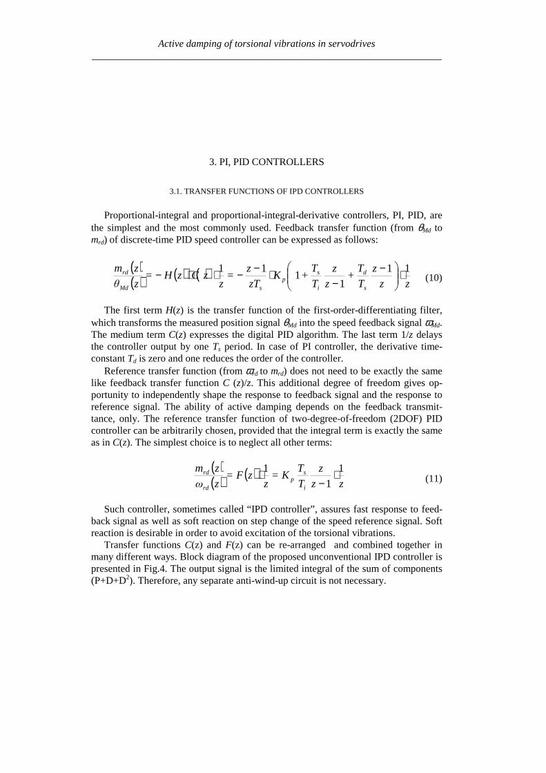
Active damping of torsional vibrations in servodrives_____________________________________________________________________
3 PI PID CONTROLLERS
31 TRANSFER FUNCTIONS OF IPD CONTROLLERS
Proportional-integral and proportional-integral-derivative controllers PI PID arethe simplest and the most commonly used Feedback transfer function (from θMd tomrd) of discrete-time PID speed controller can be expressed as follows
( )( ) ( ) ( )
zz
z
T
T+
z
z
T
T+K
zT
z=
zzCzH=
zθ
zm
s
d
i
sp
sMd
rd 11
11
11 sdot
minusminus
sdotminusminussdotsdotminus (10)
The first term H(z) is the transfer function of the first-order-differentiating filterwhich transforms the measured position signal θMd into the speed feedback signal ωMdThe medium term C(z) expresses the digital PID algorithm The last term 1z delaysthe controller output by one Ts period In case of PI controller the derivative time-constant Td is zero and one reduces the order of the controller
Reference transfer function (from ωrd to mrd) does not need to be exactly the samelike feedback transfer function C (z)z This additional degree of freedom gives op-portunity to independently shape the response to feedback signal and the response toreference signal The ability of active damping depends on the feedback transmit-tance only The reference transfer function of two-degree-of-freedom (2DOF) PIDcontroller can be arbitrarily chosen provided that the integral term is exactly the sameas in C(z) The simplest choice is to neglect all other terms
( )( ) ( )
zz
z
T
TK=
zzF=
zω
zm
i
sp
rd
rd 1
1
1 sdotminus
sdot (11)
Such controller sometimes called ldquoIPD controllerrdquo assures fast response to feed-back signal as well as soft reaction on step change of the speed reference signal Softreaction is desirable in order to avoid excitation of the torsional vibrations
Transfer functions C(z) and F(z) can be re-arranged and combined together inmany different ways Block diagram of the proposed unconventional IPD controller ispresented in Fig4 The output signal is the limited integral of the sum of components(P+D+D2) Therefore any separate anti-wind-up circuit is not necessary
Active damping of torsional vibrations in servodrives_____________________________________________________________________
Fig4 Block diagram of the proposed IPD controller
32 ACTIVE DAMPING WHEN DELAYS ARE NEGLIGIBLE
Speed control of two-inertia system by the PIPID controller was analysed in [21]using the pole placement method Delays were neglected ideal speed feedback wasassumed and the fourth-order continuous-time domain model represented the wholesystem An arbitrary placement of the poles of the closed speed control loop was notpossible for the flexible coupled drive However it was found that good dampingcould be obtained for limited range of drive parameters Three different methods ofchoosing pole location were proposed The method assuming equality of the real partsof both complex pole pairs seemed the most promising The damping coefficient ξ1for one pole pair could be chosen as design parameter while the second oneξ2 resulted from the mentioned equality The PI controller set up according to thismethod was able to damp vibration for the inertia ratio within the range of 1 lt R lt 4
Several analyses and simulations have been carried out to find the parameters of PIcontroller at which the shortest setting time is obtained for each value of inertia ratioR It has been found that the damping coefficient ξ1 of the slower pole pair should beset to the value higher than 08 for R gt 15 and to about 064 for R=1 The perform-ance of PI control in the range of 15ltRlt4 can be characterised by the followingfeatures
ndash Setting time is about 15 ARFndash Speed drop ∆ωmax after step change of the load torque mL is about 5middotARFmiddotmLKsh
The authors [21] proposed PID control if the inertia ratio R is greater than 4 or lessthan 1 The derivative action should virtually reduce the motor inertia JM to the newvalue JM at which the inertia ratio R is sufficient for PI control Controller gain Kp andtime-constant Ti can be calculated as previously provided JM (virtual inertia) is usedinstead of real value JM
Active damping of torsional vibrations in servodrives_____________________________________________________________________
33 ACTIVE DAMPING WHEN DELAY CONSIDERED
Numerous simulation experiments have been carried out in order to find the rangeof delay at which the PIPID controller set up according to previously describedrules could be used The results of this investigation are shown in Fig 5 and can besummarised as follows
ndash Delay TmiddotNTF not greater than 01 is acceptable for the inertia ratio in the range1ltRlt4 In that case the performance is only slightly degraded but the delay mar-gin is low Even the 15 increase in delay can be enough to make the system un-stable
ndash For the inertia ratio higher than 75 or lower than 05 even very small delaysTmiddotNTFlt005 can not be neglected
Fig 5 Active damping with controller parameters dependent only on R a) gain and time-constants
b) stability boundary as function of R and TmiddotNTF c) setting time for various delays TmiddotNTF
Active damping of torsional vibrations in servodrives_____________________________________________________________________
Fig 6 Active damping with controller parameters dependent on R and delay a) gain Kpb) integral time-constant Ti c) derivative time-constant TD
d) setting time after step change of virtual disturbance torque mdd
The aim of further work was to widen the range of admissible delays by changingthe controller parameters Considerable improvement has been achieved Optimal set-tings of Kp Ti Td shown in Fig 6 a b c as a function of both R and TmiddotNTF havebeen found by simulations experiment The characteristics of setting time shown inFig 6 d and can be summarised as follows
ndash Stable operation is possible in the wide investigated range of parameters025ltRlt8 0ltTmiddotNTFlt04
ndash For moderate delays (TmiddotNTFlt015) the performance is slightly better than previ-ously for no-delay conditions
ndash For higher values of total delay (TmiddotNTFgt015) the setting time can be considera-bly longer
Exemplary waveforms showing damping ability of the IPD controller set up ac-cording to Fig 5 and Fig 6 are presented in Fig7
Active damping of torsional vibrations in servodrives_____________________________________________________________________
4 STATE CONTROLLER WITH STATE OBSERVER
41 STRUCTURE OF THE SYSTEM
The state controller is one of the classical solutions of the control task It is oftenused also for the systems with flexibility [1] [2] [3] [12] and [20] According to as-sumption of this work many structures of the system with state controller intended forhigh power drives should be rejected because of additional sensors installed on the loadside The structure using only the position encoder integrated with the motor is shown inFig 8 There are elements of digital processing (sampler differentiation procedure) ofposition signal in the feedback path of the model They introduce to the path the delay Tf
equal to the time step Ts of the DSP controller Other blocks in the model are simulatedin continuous-time domain Their delays are included to the block modelling torquecontrol loop (total delay Tg of the block)
The state controller uses the signals of motor mM and shaft shm torque as well as
motor ωMd and load Lω speed The feedback from signal mM is easy to realise as themotor torque is usually proportional to the current (whose signal is measurable) In somecases the reference torque mr can be used instead of motor torque mM This solution cor-
responds to the controller shown in Fig 3 In order to have the signals shm and Lω thecontroller algorithm must realise also observer procedure In frame of presented on
Fig 8 controller it is also possible to test system without internal feedback signal shm or
Lω
Fig7 Waveforms of motor speed ωM and load speed ωL as responses on step change of reference
speed ωrd and following step change of signal mdd a) with controller set up according to [21] and
Fig5 a b) with proposed settings according to Fig 6 (R=2 TmiddotNTF=011)
Active damping of torsional vibrations in servodrives_____________________________________________________________________
z
11minus
sT
1 θMd
Differentiation Sampler
Quantiser
Digital processing delay Tf = Ts
Statecontroller
gsTeminus
2-masssystem(fig 2)
θM
mL
mM
Torque control loop inclu-ding additional delay
mr
Stateobserver
shm
Lω
ωMd
ωr
mM bull
bull
bull
Fig 8 Model of the system with state controller and state observer
42 THE STATE CONTROLLER
The linear state controller operates according to the equation
LLshshMdMMmrr ωkmkωkmkωkm minusminusminusminus= ω (12)
where the gains of component with reference motor and load speed should fulfil therelation
LM kkk +=ω (13)
in order to have no load operation without speed error Therefore if
ωkakM sdot= (14)
then
( ) ωkakL sdotminus= 1 (15)
Active damping of torsional vibrations in servodrives_____________________________________________________________________
where the a is the weight of the motor speed feedback and 1ndasha is the weight of the loadspeed feedback The coefficients kω a km and ksh are the parameters of the controllerinfluencing the properties of the system These parameters are selected using optimisa-tion procedure as described in subchapter 44
Instead of the linear state controller the non-linear one described in [16] can be usedIt should give further improving the properties also in the systems with delay
43 THE STATE OBSERVER
The observer (Fig 9) contains the two-mass model (Fig 2) and correction elements
Reduction of the error between the motor speed ωMd and speed Mω from the observer tothe value near by zero allows reproducing the signals of the load speed ωL and shafttorque msh A quality of it depends on the gains h1 h4 In order to reproduce the loadtorque mL the error of the observation of motor speed is integrated in the circuit with thegain h4
The signal Lm can be used in the observer for compensation of the speed drop due to
loading the drive For this purpose the signal Lm should be introduced to the torquesumming point (dashed line in the Fig 9) with positive gain hL The principle of thiscompensation is given in [10] together with derivation of the following condition
m
shL k
kh
++=
11 (16)
at which the speed is invariant with regard to loading
44 RESULTS OF THE PRELIMINARY SIMULATION
Preliminary the system from Fig 8 was simulated without the observer i eksh=kL=0 and a = 1 The inertia ratio was R = 1 During investigation the total delay Twas varied Every time the T was divided in two parts Tg = 2T3 and Tf = T3 Themaximum value of index TNTF was searched at which the controller is able active todamp the oscillations For each value of delay the gains kω and km of the controller wereoptimised The maximum ratio of two successive amplitudes of the oscillating quantitieswas the optimisation criterion
The results of the simulation are given in Table 1 It is seen that with increase ofstiffness (delay) the optimum value of feedback gains decrease Simultaneously the set-ting time becomes longer State controller having only motor speed and motor torque
Active damping of torsional vibrations in servodrives_____________________________________________________________________
Fig 9 The state observer
feedback paths is able to damp the oscillation in the system with stiffness up to about023 (the highest value in the Table 1)
A better result is expected after additionally feeding the controller from the observerwith the feedback signals of the shaft torque and load speed However the degree ofimprovement of system properties will depend strongly on encoder inaccuracy and alsoon delay as the observer uses non-actual values of the quantities
Table 1 The dependence of the controller parameters and setting time on thestiffness factor for the system with state controller having only two feedback paths
Stiffness factorTNTF 0101 0135 0169 0230
kω [Nsrad] 1 0556 0333 0133Controllerparameters km [-] 1 0667 0333 0167
Setting time multipliedby the ARF 113 163 424 very long
The controller parameters are relate to first data column
Active damping of torsional vibrations in servodrives_____________________________________________________________________
5 SLOW RESONANCE RATIO CONTROLLER
The slow resonance ratio control (SRRC) was firstly introduced as a method forvibration suppression and disturbance rejection in torsional systems [1] [6] [7]SRRC algorithm feeds back the torsional torque estimated by a model-based distur-bance observer so to change the virtual motor inertia to an arbitrary selected valueThis means that the resonance frequency NTF and then the resonance ratioH=NTFARF can be changed
Fig 2e-sT
JM
1-K
Differential
2DOF PI
LPF(Tq)LPF(Tq)
Differential
K+
++-
+-
digital speed controllerωrd
ωMd θMd
θM
mrd
mM
mL
mr
samplerquantizer
torque control loopand additional delay
2-mass systemextrapolator
msh^
Fig 10 Block diagram of resonance control
The detail of the resonance ratio control with shaft torque observer is reported inFig 10 where the mechanical model from Fig 2 has been used The digital speedcontrollerrsquos model has been simplified by fusion all delays in the closed loop torquecontrol Based on measurement motor speed ωMd and reference torque mrd the shaft
torque shm is estimated Only (1-K) portion of the estimated shaft torque is fed backBy doing this the designed virtual motor inertia JM-des is defined as
KJJ MdesM =minus (17)
This means that virtual inertia ratio Rdes can be expressed as
KRJJR LdesMdes sdot== minus (18)
Active damping of torsional vibrations in servodrives_____________________________________________________________________
The resonance ratio H could be changed to value desdes RH += 1
The slow disturbance observer was originally proposed by Iwata and Itoh [8]They proposed that the optimal cut-off frequency should be a little lower than theanti-resonant frequency ARF The optimal observer time constant Tq is calculated onbasis R and Rdes as given by [17]
ARFRRRR
RR
Tdesdes
des
q sdotsdot
++
++
++=
π21
21
43
1
4
31
When PI speed controller is used the characteristic equation of the closed drive sys-tem is
01
12
23
34
4)( asasasasasP ++++= (19)
The coefficients a4ndasha0 can be selected according to desired dynamical propertiesof whole system The effective method is Coefficient Diagram Method based on Ma-nabe polynomials [15] In this method design specifications are equivalent time con-stant (τ ) and stability indices (γi) For analysed system τ is defined as
01 aa=τ (20)
and stability indices should be selected as follow
2 2 5242
23
331
22
220
21
1 ======aa
a
aa
a
aa
a γγγ (21)
By solving these equations the optimal resonance ratio can be determined
580 sdot=desH This correspond to inertia ratio Rdes=115
From (18) the coefficient K is calculated The controller gains are given by (com-pare [7])
22
)(11
1611
220
ARFJK
ARFJK
Li
Lp
sdotsdotsdot=
sdotsdotsdot=
π
π
(22)
Active damping of torsional vibrations in servodrives_____________________________________________________________________
Simulation experiments has been carried out to find the range of stabile parameters atwhich presented SRRC could be used The results of this investigation can be summa-rised as followsStability boundary
- TmiddotNTF gt 012 for 08 lt R lt 2- TmiddotNTF gt 010 for 08 lt R lt 8- TmiddotNTF gt 003 for 035 lt R lt 8
Setting time Tω - ARF Tω lt18 for TmiddotNTF = 01 and 08 lt R lt 2- ARF Tω lt42 for TmiddotNTF = 008 and 2 lt R lt 8- ARF Tω lt51 for TmiddotNTF = 006 and 05 lt R lt 1
Presented slow resonance ratio controller is well fitting for system with relativelarge load inertia in relation to motor inertia In such case the virtual motor inertia isincreasing through using feedback coefficient K smaller than 1 and the whole systemis robust to real-time delays However if the load inertia is small feedback coeffi-cient K greater than 1 is needed and system is sensitive to any time lags It should benoted that when the motor inertia is much larger than the load inertia the resonanceratio control makes the disturbance response worse This fact suggests that the vibra-tion suppression and the disturbance rejection are opposite objectives [7]
6 LINEAR-QUADRATIC CONTROLLER WITH KALMAN FILTER
61 STATE AND DISTURBANCES OBSERVER
When using the LQ-controller state vector should be available State variables thatcannot be measured should be estimated
The Kalman Filter is one of proposed estimators [11] [12] [13] [17] Kalmanfilter theory allows estimating all state variables Theory presented in [11] determinesthe state variables They could be disturbed by Gaussian white noise which repre-sents all error sources and model inaccuracy [11] This is a narrow assumption thathas been avoided in his work This causes difficulties with theoretical tuning rules
Basing on filtering knowledge [11] the model of the system can be expressed bystate (23) and measurement (24) equations
1n e n e n nx x u w+ = + +A B (23)
n e n ny x v= +C (24)
Active damping of torsional vibrations in servodrives_____________________________________________________________________
where the control signal u is equal to the torque command mr and the output vector yis equal to mechanical position θ In equations (23) and (24) w represents a processnoise and v - measurement noise
It is assumed that the disturbing load torque (mL) is a part of measurement noiseand a part of state vector The assumption is only valid when the derivative of loadtorque is near to zero
0L
dm
dtasymp (25)
The state vector of observer has been extended by new estimated variable (Lm )
ˆˆ ˆˆ ˆ ˆT
M L sh Lx m mω ω θ = (26)
New state space matrices are equal
10 0 0 0
1 10 0 0
0 0 0
0 0 0 0 0
1 0 0 0 0
M
L Le
sh sh
J
J J
K K
minus minus =
minus
A
=
0
0
0
0
1
M
e
J
B
0
0
0
0
1
e
=
C (272829)
The equations of estimator are given by
( )| | 1 | 1
1| |
ˆ ˆ ˆ
ˆ ˆ ˆ
n n n n e n e n n
n n e n n e n
x x y x
x x u
minus minus
+
= + minus
= +
K C
A B (30)
where Ke is a Kalman filter gains which is computed by solving Ricatti equation[11] The gains can be calculated using recursive algorithm only one time and can bevalid for each step of control algorithm The noisersquos covariance of presented system(025ltRlt8 Ksh=1 equivalent of 14bit encoder) can be determine by matrix Qe
Active damping of torsional vibrations in servodrives_____________________________________________________________________
22
14
202 02 10 10
2e diag π =
Q (31)
which values represent covariances respectively with vector x elements The noisersquoscovariance of output signal may be described by
2
e 14
2
2R
π =
(32)
Theoretically the appropriate values should be real covariance but they was se-lected experimentally during system investigations It is noticed that last element ofQe matrix and Re is linked with the one known error It is caused by the quantisationduring obtaining real position from the 14-bit encoder
62 LQ CONTROL STRATEGY
The LQ-controller has several good properties [4] [9] and [18] It is applicable tomultivariable and time-varying systems when a model of the system can be availablein state space form (Fig 11) Changing the relations between the magnitude of ele-ments in weighting matrices we obtain compromise between the control speed and themagnitudes of control signals
Fig 11 Model of the system with LQ-controller and Kalman filter
The finding of answer presented in [9] is applicable to our system The generalformulation of the problem is to minimise the performance index J The following
Active damping of torsional vibrations in servodrives_____________________________________________________________________
deviations from steady state has been defined ∆x ∆u (for state and control variablesrespectively) The designed problem was reformulated to LQ-compensator with newdefined performance index J
( ) ( )( )2
0
T
r rJ R ux xinfin
= + ∆∆ ∆int Q (33)
where Qr and Rr are defined tuning matricesIn state controller the control-input signal is given by follows
r
xu
p
= minus
K (34)
Partitioning Kr and using integral control to cancel steady-state error
( )0
ˆt
M rdp dtω ω= minusint (35)
the control input signal yields
[ ] ( )1 2 3
0
ˆ
ˆ ˆ
ˆ
M t
L p M rd
sh
u K K K K dt
m
ωω ω ω = minus minus minus
int (36)
The main problem during solving LQ regulator is proper choosing the performanceindex J As shown in [9] Qr and Rr are given as
0 0
0 0
0 0 0 0
0 0 0
r
α αα α β
δ
minus minus + =
Q rR ε= (3738)
Performance index (33) can be expressed in more practical form
Active damping of torsional vibrations in servodrives_____________________________________________________________________
( ) ( )( ) ( )
2 2
2 20
M L L Ls
s s
J dtp p u u
α ω ω β ω ω
δ ε
infin minus + minus + = + minus + minus
int (39)
where Greek symbols mark weighting for α ndash torsional vibration suppression
β ndash command following δ ndash steady-state error ε ndash control input
The weight factors were selected experimentally α = 1 β = 100 δ = 100 ε = 01
63 SIMULATION RESULTS
Simulation experiments confirmed that there exists a range of delay at which theLQ-controller using signals dealt by Kalman filter can be constructed The wholesystem has been experimentally tuned (without any optimisation) to check how thetotal delay T influences system performance The preliminary results of investigationcan be briefly formulated as follows
ndash Delay TsdotNTF lt 008 has very small influence on system performance
ndash The setting time without delay is ARFsdotTω asymp 2 Similar performance can be ob-
tained for increasing delay only in limited range of inertia ratio
ndash TsdotNTF lt 008 and 025ltRlt05
ndash TsdotNTF lt 011 and R=1
ndash TsdotNTF lt 02 and 2 lt R lt 8
ndash When TsdotNTF lt 035 the system is stable but the setting time is unacceptable
large
7 CONCLUSION
It is possible to actively damp torsional vibration using single feedback signal fromencoder only Damping ability depends on the inertia ratio R and total delay T in thespeed control loop Because single feedback signal is considered and the controllerhas single output all analysed controllers can be treated as digital filters Apart fromvarious internal descriptions all controllers actually differ only in filter order and co-efficients Methods of calculation and tuning controller gains (or filter coefficients)are also different Unfortunately no systematic design methods have been found forthe analysed controllers Only heuristic approach for controller tuning was tested Themost complete and most promising results have been obtained for the unconventional
Active damping of torsional vibrations in servodrives_____________________________________________________________________
IPD controllers The near-optimum parameters have been found by simulation ex-periments for wide range of R and T These parameters can be directly applied in realPID controlled industrial drives
Another considered methods have been elaborated only partially Because theyconstitute filters of higher order than simple PI-controller probably better resultscould be obtained This possible advantage has not been fully confirmed in this workAuthors concentrate on practical rules for choosing suitable parameters of state con-troller and observer as well as gains of Kalman filter and LQ compensator
ACKONWLEDGEMENT
This work was partially supported by the grant 3 T10A 026 28
REFERENCES
[1] BOLOGNANI S VENTURATO A ZIGLIOTTO M Theoretical and experimental comparisonof speed controllers for elastic two-mass-systems Proc31st APESCrsquo2000 vol 3 pp1087-10922000
[2] DEUR J PERIC N Analysis of speed control system for electrical drives with elastic transmissionProc of the IEEE Int Symp ISIErsquo99 Bled Slovenia vol 2 pp 624-630 1999
[3] DEUR J PERIC N Pointing and tracking position control system for electrical drives with elastictransmission Proc 9th Int Conf PEMCrsquo2000 Kosice Slovak Republic pp7-1-7-6 2000
[4] FRANKLIN GF POWELL JD WORKMAN ML Digital Control of Dynamic Systems 3rdEdition Prentice Hall 1997
[5] GIERLOTKA K ZALEŚNY P Metoda obliczania parametroacutew układu regulacji napędu z połą-czeniem spręŜystym z dodatkowymi sprzęŜeniami zwrotnymi ZN Politechniki Śląskiej Elektrykaz170 (1999) str 65-72
[6] HORI Y SAWADA H CHUN Y Slow Resonance Ratio Control for Vibration Suppression andDisturbance Rejection in Torsional System IEEE Trans on Industrial Electronics vol 34 pp 162-168 1999
[7] HORI Y Comparison of Torsional Vibration Controls based on the Fast and Slow DisturbanceObservers Proc Int Conf IPEC95 Vol1 pp440-446 Yokohama 1995
[8] IWATA M ITOH S High Performance and Adaptive Motion Control System Based on IdentifiedMechanical Parameter Proc 3rd Int Workshop on Advanced Motion Control 1994 Berkeley
[9] JI J-K SUL S-K Kalman filter and LQ based speed controller for torsional vibration suppres-sion in a 2-mass motor drive system IEEE Trans Ind Electron vol 42 no 6 pp564ndash571 1995
[10] KALEJTA T MUSZYŃSKI R State observer for servodrive with flexibility Proc 4th Int SympELECTROMOTION`01 Bologna Italy vol 1 pp 159-164 2001
[11] KALMAN RE New Approach to Linear Filtering and Prediction Problems Trans of the ASMEJournal of Basic Engineering 1960 pp 374-382
[12] ORŁOWSKA-KOWALSKA T SZABAT K Zastosowanie regulatora stanu w układzie napędo-wym z połączeniem spręŜystym MaterVI Kraj Konf SENE 2003 tom III pp 679-685
[13] ORŁOWSKA-KOWALSKA T SZABAT K State Feedback Control of Two-Mass System withState Estimator Proc Int ConfEDPErsquo2003 Hihg Tatras Slovak Rep pp 590-595 2003
[14] ORŁOWSKA-KOWALSKA T SZABAT K Optimization of fuzzy-logic speed controller for DC
Active damping of torsional vibrations in servodrives_____________________________________________________________________
drive system with elastic joints IEEE Trans on Ind Applic vol 40 no 4 pp1138-1144 2004[15] MANABE S Coefficient Diagram Method Proc 14th IFAC Symp on Automatic Control in Aero-
space Seoul1998[16] MUSZYŃSKI R KACZMAREK T The elastic servo drive with state controller Archives of
Electrical Engineering vol LII no 2 pp 185-200 2003[17] SHIN D-J HUH U-Y Robust motion controller design for servo system with 2 mass characteris-
tics Proc 6th Inter Workshop on Advanced Motion Control 2000 pp 423-426[18] STEFANI R SAVANT C SHAHIAN B HOSTETTER G Design of Feedback Control Systems
Saunders College Publisher 1994[19] SZABAT K ORŁOWSKA-KOWALSKA T Tłumienie oscylacji prędkości w układzie napędowym
z połaczeniem spręŜystym Przegląd Elektrotechniczny vol LXXIX no 7-8 pp 474-482 2003[20] ШИЯНОВ А И МЕДВЕДЕВ ΒАМОРОЗОВ СВ Асинхронный злектропривод с упругой
нагрузкой и адаптивным регулятором ЗЛЕКТРИЧЕСТВО no 2 pp47divide49 2001[21] ZHANG G FURUSHO J Speed Control of Two-Inertia System by PIPID control IEEE Trans on
Industrial Electronics vol 47 no3 pp 603-609 2000
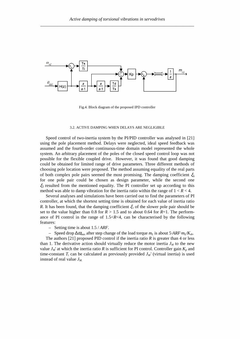
Active damping of torsional vibrations in servodrives_____________________________________________________________________
Fig4 Block diagram of the proposed IPD controller
32 ACTIVE DAMPING WHEN DELAYS ARE NEGLIGIBLE
Speed control of two-inertia system by the PIPID controller was analysed in [21]using the pole placement method Delays were neglected ideal speed feedback wasassumed and the fourth-order continuous-time domain model represented the wholesystem An arbitrary placement of the poles of the closed speed control loop was notpossible for the flexible coupled drive However it was found that good dampingcould be obtained for limited range of drive parameters Three different methods ofchoosing pole location were proposed The method assuming equality of the real partsof both complex pole pairs seemed the most promising The damping coefficient ξ1for one pole pair could be chosen as design parameter while the second oneξ2 resulted from the mentioned equality The PI controller set up according to thismethod was able to damp vibration for the inertia ratio within the range of 1 lt R lt 4
Several analyses and simulations have been carried out to find the parameters of PIcontroller at which the shortest setting time is obtained for each value of inertia ratioR It has been found that the damping coefficient ξ1 of the slower pole pair should beset to the value higher than 08 for R gt 15 and to about 064 for R=1 The perform-ance of PI control in the range of 15ltRlt4 can be characterised by the followingfeatures
ndash Setting time is about 15 ARFndash Speed drop ∆ωmax after step change of the load torque mL is about 5middotARFmiddotmLKsh
The authors [21] proposed PID control if the inertia ratio R is greater than 4 or lessthan 1 The derivative action should virtually reduce the motor inertia JM to the newvalue JM at which the inertia ratio R is sufficient for PI control Controller gain Kp andtime-constant Ti can be calculated as previously provided JM (virtual inertia) is usedinstead of real value JM
Active damping of torsional vibrations in servodrives_____________________________________________________________________
33 ACTIVE DAMPING WHEN DELAY CONSIDERED
Numerous simulation experiments have been carried out in order to find the rangeof delay at which the PIPID controller set up according to previously describedrules could be used The results of this investigation are shown in Fig 5 and can besummarised as follows
ndash Delay TmiddotNTF not greater than 01 is acceptable for the inertia ratio in the range1ltRlt4 In that case the performance is only slightly degraded but the delay mar-gin is low Even the 15 increase in delay can be enough to make the system un-stable
ndash For the inertia ratio higher than 75 or lower than 05 even very small delaysTmiddotNTFlt005 can not be neglected
Fig 5 Active damping with controller parameters dependent only on R a) gain and time-constants
b) stability boundary as function of R and TmiddotNTF c) setting time for various delays TmiddotNTF
Active damping of torsional vibrations in servodrives_____________________________________________________________________
Fig 6 Active damping with controller parameters dependent on R and delay a) gain Kpb) integral time-constant Ti c) derivative time-constant TD
d) setting time after step change of virtual disturbance torque mdd
The aim of further work was to widen the range of admissible delays by changingthe controller parameters Considerable improvement has been achieved Optimal set-tings of Kp Ti Td shown in Fig 6 a b c as a function of both R and TmiddotNTF havebeen found by simulations experiment The characteristics of setting time shown inFig 6 d and can be summarised as follows
ndash Stable operation is possible in the wide investigated range of parameters025ltRlt8 0ltTmiddotNTFlt04
ndash For moderate delays (TmiddotNTFlt015) the performance is slightly better than previ-ously for no-delay conditions
ndash For higher values of total delay (TmiddotNTFgt015) the setting time can be considera-bly longer
Exemplary waveforms showing damping ability of the IPD controller set up ac-cording to Fig 5 and Fig 6 are presented in Fig7
Active damping of torsional vibrations in servodrives_____________________________________________________________________
4 STATE CONTROLLER WITH STATE OBSERVER
41 STRUCTURE OF THE SYSTEM
The state controller is one of the classical solutions of the control task It is oftenused also for the systems with flexibility [1] [2] [3] [12] and [20] According to as-sumption of this work many structures of the system with state controller intended forhigh power drives should be rejected because of additional sensors installed on the loadside The structure using only the position encoder integrated with the motor is shown inFig 8 There are elements of digital processing (sampler differentiation procedure) ofposition signal in the feedback path of the model They introduce to the path the delay Tf
equal to the time step Ts of the DSP controller Other blocks in the model are simulatedin continuous-time domain Their delays are included to the block modelling torquecontrol loop (total delay Tg of the block)
The state controller uses the signals of motor mM and shaft shm torque as well as
motor ωMd and load Lω speed The feedback from signal mM is easy to realise as themotor torque is usually proportional to the current (whose signal is measurable) In somecases the reference torque mr can be used instead of motor torque mM This solution cor-
responds to the controller shown in Fig 3 In order to have the signals shm and Lω thecontroller algorithm must realise also observer procedure In frame of presented on
Fig 8 controller it is also possible to test system without internal feedback signal shm or
Lω
Fig7 Waveforms of motor speed ωM and load speed ωL as responses on step change of reference
speed ωrd and following step change of signal mdd a) with controller set up according to [21] and
Fig5 a b) with proposed settings according to Fig 6 (R=2 TmiddotNTF=011)
Active damping of torsional vibrations in servodrives_____________________________________________________________________
z
11minus
sT
1 θMd
Differentiation Sampler
Quantiser
Digital processing delay Tf = Ts
Statecontroller
gsTeminus
2-masssystem(fig 2)
θM
mL
mM
Torque control loop inclu-ding additional delay
mr
Stateobserver
shm
Lω
ωMd
ωr
mM bull
bull
bull
Fig 8 Model of the system with state controller and state observer
42 THE STATE CONTROLLER
The linear state controller operates according to the equation
LLshshMdMMmrr ωkmkωkmkωkm minusminusminusminus= ω (12)
where the gains of component with reference motor and load speed should fulfil therelation
LM kkk +=ω (13)
in order to have no load operation without speed error Therefore if
ωkakM sdot= (14)
then
( ) ωkakL sdotminus= 1 (15)
Active damping of torsional vibrations in servodrives_____________________________________________________________________
where the a is the weight of the motor speed feedback and 1ndasha is the weight of the loadspeed feedback The coefficients kω a km and ksh are the parameters of the controllerinfluencing the properties of the system These parameters are selected using optimisa-tion procedure as described in subchapter 44
Instead of the linear state controller the non-linear one described in [16] can be usedIt should give further improving the properties also in the systems with delay
43 THE STATE OBSERVER
The observer (Fig 9) contains the two-mass model (Fig 2) and correction elements
Reduction of the error between the motor speed ωMd and speed Mω from the observer tothe value near by zero allows reproducing the signals of the load speed ωL and shafttorque msh A quality of it depends on the gains h1 h4 In order to reproduce the loadtorque mL the error of the observation of motor speed is integrated in the circuit with thegain h4
The signal Lm can be used in the observer for compensation of the speed drop due to
loading the drive For this purpose the signal Lm should be introduced to the torquesumming point (dashed line in the Fig 9) with positive gain hL The principle of thiscompensation is given in [10] together with derivation of the following condition
m
shL k
kh
++=
11 (16)
at which the speed is invariant with regard to loading
44 RESULTS OF THE PRELIMINARY SIMULATION
Preliminary the system from Fig 8 was simulated without the observer i eksh=kL=0 and a = 1 The inertia ratio was R = 1 During investigation the total delay Twas varied Every time the T was divided in two parts Tg = 2T3 and Tf = T3 Themaximum value of index TNTF was searched at which the controller is able active todamp the oscillations For each value of delay the gains kω and km of the controller wereoptimised The maximum ratio of two successive amplitudes of the oscillating quantitieswas the optimisation criterion
The results of the simulation are given in Table 1 It is seen that with increase ofstiffness (delay) the optimum value of feedback gains decrease Simultaneously the set-ting time becomes longer State controller having only motor speed and motor torque
Active damping of torsional vibrations in servodrives_____________________________________________________________________
Fig 9 The state observer
feedback paths is able to damp the oscillation in the system with stiffness up to about023 (the highest value in the Table 1)
A better result is expected after additionally feeding the controller from the observerwith the feedback signals of the shaft torque and load speed However the degree ofimprovement of system properties will depend strongly on encoder inaccuracy and alsoon delay as the observer uses non-actual values of the quantities
Table 1 The dependence of the controller parameters and setting time on thestiffness factor for the system with state controller having only two feedback paths
Stiffness factorTNTF 0101 0135 0169 0230
kω [Nsrad] 1 0556 0333 0133Controllerparameters km [-] 1 0667 0333 0167
Setting time multipliedby the ARF 113 163 424 very long
The controller parameters are relate to first data column
Active damping of torsional vibrations in servodrives_____________________________________________________________________
5 SLOW RESONANCE RATIO CONTROLLER
The slow resonance ratio control (SRRC) was firstly introduced as a method forvibration suppression and disturbance rejection in torsional systems [1] [6] [7]SRRC algorithm feeds back the torsional torque estimated by a model-based distur-bance observer so to change the virtual motor inertia to an arbitrary selected valueThis means that the resonance frequency NTF and then the resonance ratioH=NTFARF can be changed
Fig 2e-sT
JM
1-K
Differential
2DOF PI
LPF(Tq)LPF(Tq)
Differential
K+
++-
+-
digital speed controllerωrd
ωMd θMd
θM
mrd
mM
mL
mr
samplerquantizer
torque control loopand additional delay
2-mass systemextrapolator
msh^
Fig 10 Block diagram of resonance control
The detail of the resonance ratio control with shaft torque observer is reported inFig 10 where the mechanical model from Fig 2 has been used The digital speedcontrollerrsquos model has been simplified by fusion all delays in the closed loop torquecontrol Based on measurement motor speed ωMd and reference torque mrd the shaft
torque shm is estimated Only (1-K) portion of the estimated shaft torque is fed backBy doing this the designed virtual motor inertia JM-des is defined as
KJJ MdesM =minus (17)
This means that virtual inertia ratio Rdes can be expressed as
KRJJR LdesMdes sdot== minus (18)
Active damping of torsional vibrations in servodrives_____________________________________________________________________
The resonance ratio H could be changed to value desdes RH += 1
The slow disturbance observer was originally proposed by Iwata and Itoh [8]They proposed that the optimal cut-off frequency should be a little lower than theanti-resonant frequency ARF The optimal observer time constant Tq is calculated onbasis R and Rdes as given by [17]
ARFRRRR
RR
Tdesdes
des
q sdotsdot
++
++
++=
π21
21
43
1
4
31
When PI speed controller is used the characteristic equation of the closed drive sys-tem is
01
12
23
34
4)( asasasasasP ++++= (19)
The coefficients a4ndasha0 can be selected according to desired dynamical propertiesof whole system The effective method is Coefficient Diagram Method based on Ma-nabe polynomials [15] In this method design specifications are equivalent time con-stant (τ ) and stability indices (γi) For analysed system τ is defined as
01 aa=τ (20)
and stability indices should be selected as follow
2 2 5242
23
331
22
220
21
1 ======aa
a
aa
a
aa
a γγγ (21)
By solving these equations the optimal resonance ratio can be determined
580 sdot=desH This correspond to inertia ratio Rdes=115
From (18) the coefficient K is calculated The controller gains are given by (com-pare [7])
22
)(11
1611
220
ARFJK
ARFJK
Li
Lp
sdotsdotsdot=
sdotsdotsdot=
π
π
(22)
Active damping of torsional vibrations in servodrives_____________________________________________________________________
Simulation experiments has been carried out to find the range of stabile parameters atwhich presented SRRC could be used The results of this investigation can be summa-rised as followsStability boundary
- TmiddotNTF gt 012 for 08 lt R lt 2- TmiddotNTF gt 010 for 08 lt R lt 8- TmiddotNTF gt 003 for 035 lt R lt 8
Setting time Tω - ARF Tω lt18 for TmiddotNTF = 01 and 08 lt R lt 2- ARF Tω lt42 for TmiddotNTF = 008 and 2 lt R lt 8- ARF Tω lt51 for TmiddotNTF = 006 and 05 lt R lt 1
Presented slow resonance ratio controller is well fitting for system with relativelarge load inertia in relation to motor inertia In such case the virtual motor inertia isincreasing through using feedback coefficient K smaller than 1 and the whole systemis robust to real-time delays However if the load inertia is small feedback coeffi-cient K greater than 1 is needed and system is sensitive to any time lags It should benoted that when the motor inertia is much larger than the load inertia the resonanceratio control makes the disturbance response worse This fact suggests that the vibra-tion suppression and the disturbance rejection are opposite objectives [7]
6 LINEAR-QUADRATIC CONTROLLER WITH KALMAN FILTER
61 STATE AND DISTURBANCES OBSERVER
When using the LQ-controller state vector should be available State variables thatcannot be measured should be estimated
The Kalman Filter is one of proposed estimators [11] [12] [13] [17] Kalmanfilter theory allows estimating all state variables Theory presented in [11] determinesthe state variables They could be disturbed by Gaussian white noise which repre-sents all error sources and model inaccuracy [11] This is a narrow assumption thathas been avoided in his work This causes difficulties with theoretical tuning rules
Basing on filtering knowledge [11] the model of the system can be expressed bystate (23) and measurement (24) equations
1n e n e n nx x u w+ = + +A B (23)
n e n ny x v= +C (24)
Active damping of torsional vibrations in servodrives_____________________________________________________________________
where the control signal u is equal to the torque command mr and the output vector yis equal to mechanical position θ In equations (23) and (24) w represents a processnoise and v - measurement noise
It is assumed that the disturbing load torque (mL) is a part of measurement noiseand a part of state vector The assumption is only valid when the derivative of loadtorque is near to zero
0L
dm
dtasymp (25)
The state vector of observer has been extended by new estimated variable (Lm )
ˆˆ ˆˆ ˆ ˆT
M L sh Lx m mω ω θ = (26)
New state space matrices are equal
10 0 0 0
1 10 0 0
0 0 0
0 0 0 0 0
1 0 0 0 0
M
L Le
sh sh
J
J J
K K
minus minus =
minus
A
=
0
0
0
0
1
M
e
J
B
0
0
0
0
1
e
=
C (272829)
The equations of estimator are given by
( )| | 1 | 1
1| |
ˆ ˆ ˆ
ˆ ˆ ˆ
n n n n e n e n n
n n e n n e n
x x y x
x x u
minus minus
+
= + minus
= +
K C
A B (30)
where Ke is a Kalman filter gains which is computed by solving Ricatti equation[11] The gains can be calculated using recursive algorithm only one time and can bevalid for each step of control algorithm The noisersquos covariance of presented system(025ltRlt8 Ksh=1 equivalent of 14bit encoder) can be determine by matrix Qe
Active damping of torsional vibrations in servodrives_____________________________________________________________________
22
14
202 02 10 10
2e diag π =
Q (31)
which values represent covariances respectively with vector x elements The noisersquoscovariance of output signal may be described by
2
e 14
2
2R
π =
(32)
Theoretically the appropriate values should be real covariance but they was se-lected experimentally during system investigations It is noticed that last element ofQe matrix and Re is linked with the one known error It is caused by the quantisationduring obtaining real position from the 14-bit encoder
62 LQ CONTROL STRATEGY
The LQ-controller has several good properties [4] [9] and [18] It is applicable tomultivariable and time-varying systems when a model of the system can be availablein state space form (Fig 11) Changing the relations between the magnitude of ele-ments in weighting matrices we obtain compromise between the control speed and themagnitudes of control signals
Fig 11 Model of the system with LQ-controller and Kalman filter
The finding of answer presented in [9] is applicable to our system The generalformulation of the problem is to minimise the performance index J The following
Active damping of torsional vibrations in servodrives_____________________________________________________________________
deviations from steady state has been defined ∆x ∆u (for state and control variablesrespectively) The designed problem was reformulated to LQ-compensator with newdefined performance index J
( ) ( )( )2
0
T
r rJ R ux xinfin
= + ∆∆ ∆int Q (33)
where Qr and Rr are defined tuning matricesIn state controller the control-input signal is given by follows
r
xu
p
= minus
K (34)
Partitioning Kr and using integral control to cancel steady-state error
( )0
ˆt
M rdp dtω ω= minusint (35)
the control input signal yields
[ ] ( )1 2 3
0
ˆ
ˆ ˆ
ˆ
M t
L p M rd
sh
u K K K K dt
m
ωω ω ω = minus minus minus
int (36)
The main problem during solving LQ regulator is proper choosing the performanceindex J As shown in [9] Qr and Rr are given as
0 0
0 0
0 0 0 0
0 0 0
r
α αα α β
δ
minus minus + =
Q rR ε= (3738)
Performance index (33) can be expressed in more practical form
Active damping of torsional vibrations in servodrives_____________________________________________________________________
( ) ( )( ) ( )
2 2
2 20
M L L Ls
s s
J dtp p u u
α ω ω β ω ω
δ ε
infin minus + minus + = + minus + minus
int (39)
where Greek symbols mark weighting for α ndash torsional vibration suppression
β ndash command following δ ndash steady-state error ε ndash control input
The weight factors were selected experimentally α = 1 β = 100 δ = 100 ε = 01
63 SIMULATION RESULTS
Simulation experiments confirmed that there exists a range of delay at which theLQ-controller using signals dealt by Kalman filter can be constructed The wholesystem has been experimentally tuned (without any optimisation) to check how thetotal delay T influences system performance The preliminary results of investigationcan be briefly formulated as follows
ndash Delay TsdotNTF lt 008 has very small influence on system performance
ndash The setting time without delay is ARFsdotTω asymp 2 Similar performance can be ob-
tained for increasing delay only in limited range of inertia ratio
ndash TsdotNTF lt 008 and 025ltRlt05
ndash TsdotNTF lt 011 and R=1
ndash TsdotNTF lt 02 and 2 lt R lt 8
ndash When TsdotNTF lt 035 the system is stable but the setting time is unacceptable
large
7 CONCLUSION
It is possible to actively damp torsional vibration using single feedback signal fromencoder only Damping ability depends on the inertia ratio R and total delay T in thespeed control loop Because single feedback signal is considered and the controllerhas single output all analysed controllers can be treated as digital filters Apart fromvarious internal descriptions all controllers actually differ only in filter order and co-efficients Methods of calculation and tuning controller gains (or filter coefficients)are also different Unfortunately no systematic design methods have been found forthe analysed controllers Only heuristic approach for controller tuning was tested Themost complete and most promising results have been obtained for the unconventional
Active damping of torsional vibrations in servodrives_____________________________________________________________________
IPD controllers The near-optimum parameters have been found by simulation ex-periments for wide range of R and T These parameters can be directly applied in realPID controlled industrial drives
Another considered methods have been elaborated only partially Because theyconstitute filters of higher order than simple PI-controller probably better resultscould be obtained This possible advantage has not been fully confirmed in this workAuthors concentrate on practical rules for choosing suitable parameters of state con-troller and observer as well as gains of Kalman filter and LQ compensator
ACKONWLEDGEMENT
This work was partially supported by the grant 3 T10A 026 28
REFERENCES
[1] BOLOGNANI S VENTURATO A ZIGLIOTTO M Theoretical and experimental comparisonof speed controllers for elastic two-mass-systems Proc31st APESCrsquo2000 vol 3 pp1087-10922000
[2] DEUR J PERIC N Analysis of speed control system for electrical drives with elastic transmissionProc of the IEEE Int Symp ISIErsquo99 Bled Slovenia vol 2 pp 624-630 1999
[3] DEUR J PERIC N Pointing and tracking position control system for electrical drives with elastictransmission Proc 9th Int Conf PEMCrsquo2000 Kosice Slovak Republic pp7-1-7-6 2000
[4] FRANKLIN GF POWELL JD WORKMAN ML Digital Control of Dynamic Systems 3rdEdition Prentice Hall 1997
[5] GIERLOTKA K ZALEŚNY P Metoda obliczania parametroacutew układu regulacji napędu z połą-czeniem spręŜystym z dodatkowymi sprzęŜeniami zwrotnymi ZN Politechniki Śląskiej Elektrykaz170 (1999) str 65-72
[6] HORI Y SAWADA H CHUN Y Slow Resonance Ratio Control for Vibration Suppression andDisturbance Rejection in Torsional System IEEE Trans on Industrial Electronics vol 34 pp 162-168 1999
[7] HORI Y Comparison of Torsional Vibration Controls based on the Fast and Slow DisturbanceObservers Proc Int Conf IPEC95 Vol1 pp440-446 Yokohama 1995
[8] IWATA M ITOH S High Performance and Adaptive Motion Control System Based on IdentifiedMechanical Parameter Proc 3rd Int Workshop on Advanced Motion Control 1994 Berkeley
[9] JI J-K SUL S-K Kalman filter and LQ based speed controller for torsional vibration suppres-sion in a 2-mass motor drive system IEEE Trans Ind Electron vol 42 no 6 pp564ndash571 1995
[10] KALEJTA T MUSZYŃSKI R State observer for servodrive with flexibility Proc 4th Int SympELECTROMOTION`01 Bologna Italy vol 1 pp 159-164 2001
[11] KALMAN RE New Approach to Linear Filtering and Prediction Problems Trans of the ASMEJournal of Basic Engineering 1960 pp 374-382
[12] ORŁOWSKA-KOWALSKA T SZABAT K Zastosowanie regulatora stanu w układzie napędo-wym z połączeniem spręŜystym MaterVI Kraj Konf SENE 2003 tom III pp 679-685
[13] ORŁOWSKA-KOWALSKA T SZABAT K State Feedback Control of Two-Mass System withState Estimator Proc Int ConfEDPErsquo2003 Hihg Tatras Slovak Rep pp 590-595 2003
[14] ORŁOWSKA-KOWALSKA T SZABAT K Optimization of fuzzy-logic speed controller for DC
Active damping of torsional vibrations in servodrives_____________________________________________________________________
drive system with elastic joints IEEE Trans on Ind Applic vol 40 no 4 pp1138-1144 2004[15] MANABE S Coefficient Diagram Method Proc 14th IFAC Symp on Automatic Control in Aero-
space Seoul1998[16] MUSZYŃSKI R KACZMAREK T The elastic servo drive with state controller Archives of
Electrical Engineering vol LII no 2 pp 185-200 2003[17] SHIN D-J HUH U-Y Robust motion controller design for servo system with 2 mass characteris-
tics Proc 6th Inter Workshop on Advanced Motion Control 2000 pp 423-426[18] STEFANI R SAVANT C SHAHIAN B HOSTETTER G Design of Feedback Control Systems
Saunders College Publisher 1994[19] SZABAT K ORŁOWSKA-KOWALSKA T Tłumienie oscylacji prędkości w układzie napędowym
z połaczeniem spręŜystym Przegląd Elektrotechniczny vol LXXIX no 7-8 pp 474-482 2003[20] ШИЯНОВ А И МЕДВЕДЕВ ΒАМОРОЗОВ СВ Асинхронный злектропривод с упругой
нагрузкой и адаптивным регулятором ЗЛЕКТРИЧЕСТВО no 2 pp47divide49 2001[21] ZHANG G FURUSHO J Speed Control of Two-Inertia System by PIPID control IEEE Trans on
Industrial Electronics vol 47 no3 pp 603-609 2000
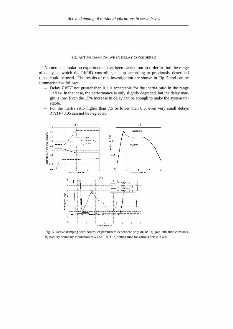
Active damping of torsional vibrations in servodrives_____________________________________________________________________
33 ACTIVE DAMPING WHEN DELAY CONSIDERED
Numerous simulation experiments have been carried out in order to find the rangeof delay at which the PIPID controller set up according to previously describedrules could be used The results of this investigation are shown in Fig 5 and can besummarised as follows
ndash Delay TmiddotNTF not greater than 01 is acceptable for the inertia ratio in the range1ltRlt4 In that case the performance is only slightly degraded but the delay mar-gin is low Even the 15 increase in delay can be enough to make the system un-stable
ndash For the inertia ratio higher than 75 or lower than 05 even very small delaysTmiddotNTFlt005 can not be neglected
Fig 5 Active damping with controller parameters dependent only on R a) gain and time-constants
b) stability boundary as function of R and TmiddotNTF c) setting time for various delays TmiddotNTF
Active damping of torsional vibrations in servodrives_____________________________________________________________________
Fig 6 Active damping with controller parameters dependent on R and delay a) gain Kpb) integral time-constant Ti c) derivative time-constant TD
d) setting time after step change of virtual disturbance torque mdd
The aim of further work was to widen the range of admissible delays by changingthe controller parameters Considerable improvement has been achieved Optimal set-tings of Kp Ti Td shown in Fig 6 a b c as a function of both R and TmiddotNTF havebeen found by simulations experiment The characteristics of setting time shown inFig 6 d and can be summarised as follows
ndash Stable operation is possible in the wide investigated range of parameters025ltRlt8 0ltTmiddotNTFlt04
ndash For moderate delays (TmiddotNTFlt015) the performance is slightly better than previ-ously for no-delay conditions
ndash For higher values of total delay (TmiddotNTFgt015) the setting time can be considera-bly longer
Exemplary waveforms showing damping ability of the IPD controller set up ac-cording to Fig 5 and Fig 6 are presented in Fig7
Active damping of torsional vibrations in servodrives_____________________________________________________________________
4 STATE CONTROLLER WITH STATE OBSERVER
41 STRUCTURE OF THE SYSTEM
The state controller is one of the classical solutions of the control task It is oftenused also for the systems with flexibility [1] [2] [3] [12] and [20] According to as-sumption of this work many structures of the system with state controller intended forhigh power drives should be rejected because of additional sensors installed on the loadside The structure using only the position encoder integrated with the motor is shown inFig 8 There are elements of digital processing (sampler differentiation procedure) ofposition signal in the feedback path of the model They introduce to the path the delay Tf
equal to the time step Ts of the DSP controller Other blocks in the model are simulatedin continuous-time domain Their delays are included to the block modelling torquecontrol loop (total delay Tg of the block)
The state controller uses the signals of motor mM and shaft shm torque as well as
motor ωMd and load Lω speed The feedback from signal mM is easy to realise as themotor torque is usually proportional to the current (whose signal is measurable) In somecases the reference torque mr can be used instead of motor torque mM This solution cor-
responds to the controller shown in Fig 3 In order to have the signals shm and Lω thecontroller algorithm must realise also observer procedure In frame of presented on
Fig 8 controller it is also possible to test system without internal feedback signal shm or
Lω
Fig7 Waveforms of motor speed ωM and load speed ωL as responses on step change of reference
speed ωrd and following step change of signal mdd a) with controller set up according to [21] and
Fig5 a b) with proposed settings according to Fig 6 (R=2 TmiddotNTF=011)
Active damping of torsional vibrations in servodrives_____________________________________________________________________
z
11minus
sT
1 θMd
Differentiation Sampler
Quantiser
Digital processing delay Tf = Ts
Statecontroller
gsTeminus
2-masssystem(fig 2)
θM
mL
mM
Torque control loop inclu-ding additional delay
mr
Stateobserver
shm
Lω
ωMd
ωr
mM bull
bull
bull
Fig 8 Model of the system with state controller and state observer
42 THE STATE CONTROLLER
The linear state controller operates according to the equation
LLshshMdMMmrr ωkmkωkmkωkm minusminusminusminus= ω (12)
where the gains of component with reference motor and load speed should fulfil therelation
LM kkk +=ω (13)
in order to have no load operation without speed error Therefore if
ωkakM sdot= (14)
then
( ) ωkakL sdotminus= 1 (15)
Active damping of torsional vibrations in servodrives_____________________________________________________________________
where the a is the weight of the motor speed feedback and 1ndasha is the weight of the loadspeed feedback The coefficients kω a km and ksh are the parameters of the controllerinfluencing the properties of the system These parameters are selected using optimisa-tion procedure as described in subchapter 44
Instead of the linear state controller the non-linear one described in [16] can be usedIt should give further improving the properties also in the systems with delay
43 THE STATE OBSERVER
The observer (Fig 9) contains the two-mass model (Fig 2) and correction elements
Reduction of the error between the motor speed ωMd and speed Mω from the observer tothe value near by zero allows reproducing the signals of the load speed ωL and shafttorque msh A quality of it depends on the gains h1 h4 In order to reproduce the loadtorque mL the error of the observation of motor speed is integrated in the circuit with thegain h4
The signal Lm can be used in the observer for compensation of the speed drop due to
loading the drive For this purpose the signal Lm should be introduced to the torquesumming point (dashed line in the Fig 9) with positive gain hL The principle of thiscompensation is given in [10] together with derivation of the following condition
m
shL k
kh
++=
11 (16)
at which the speed is invariant with regard to loading
44 RESULTS OF THE PRELIMINARY SIMULATION
Preliminary the system from Fig 8 was simulated without the observer i eksh=kL=0 and a = 1 The inertia ratio was R = 1 During investigation the total delay Twas varied Every time the T was divided in two parts Tg = 2T3 and Tf = T3 Themaximum value of index TNTF was searched at which the controller is able active todamp the oscillations For each value of delay the gains kω and km of the controller wereoptimised The maximum ratio of two successive amplitudes of the oscillating quantitieswas the optimisation criterion
The results of the simulation are given in Table 1 It is seen that with increase ofstiffness (delay) the optimum value of feedback gains decrease Simultaneously the set-ting time becomes longer State controller having only motor speed and motor torque
Active damping of torsional vibrations in servodrives_____________________________________________________________________
Fig 9 The state observer
feedback paths is able to damp the oscillation in the system with stiffness up to about023 (the highest value in the Table 1)
A better result is expected after additionally feeding the controller from the observerwith the feedback signals of the shaft torque and load speed However the degree ofimprovement of system properties will depend strongly on encoder inaccuracy and alsoon delay as the observer uses non-actual values of the quantities
Table 1 The dependence of the controller parameters and setting time on thestiffness factor for the system with state controller having only two feedback paths
Stiffness factorTNTF 0101 0135 0169 0230
kω [Nsrad] 1 0556 0333 0133Controllerparameters km [-] 1 0667 0333 0167
Setting time multipliedby the ARF 113 163 424 very long
The controller parameters are relate to first data column
Active damping of torsional vibrations in servodrives_____________________________________________________________________
5 SLOW RESONANCE RATIO CONTROLLER
The slow resonance ratio control (SRRC) was firstly introduced as a method forvibration suppression and disturbance rejection in torsional systems [1] [6] [7]SRRC algorithm feeds back the torsional torque estimated by a model-based distur-bance observer so to change the virtual motor inertia to an arbitrary selected valueThis means that the resonance frequency NTF and then the resonance ratioH=NTFARF can be changed
Fig 2e-sT
JM
1-K
Differential
2DOF PI
LPF(Tq)LPF(Tq)
Differential
K+
++-
+-
digital speed controllerωrd
ωMd θMd
θM
mrd
mM
mL
mr
samplerquantizer
torque control loopand additional delay
2-mass systemextrapolator
msh^
Fig 10 Block diagram of resonance control
The detail of the resonance ratio control with shaft torque observer is reported inFig 10 where the mechanical model from Fig 2 has been used The digital speedcontrollerrsquos model has been simplified by fusion all delays in the closed loop torquecontrol Based on measurement motor speed ωMd and reference torque mrd the shaft
torque shm is estimated Only (1-K) portion of the estimated shaft torque is fed backBy doing this the designed virtual motor inertia JM-des is defined as
KJJ MdesM =minus (17)
This means that virtual inertia ratio Rdes can be expressed as
KRJJR LdesMdes sdot== minus (18)
Active damping of torsional vibrations in servodrives_____________________________________________________________________
The resonance ratio H could be changed to value desdes RH += 1
The slow disturbance observer was originally proposed by Iwata and Itoh [8]They proposed that the optimal cut-off frequency should be a little lower than theanti-resonant frequency ARF The optimal observer time constant Tq is calculated onbasis R and Rdes as given by [17]
ARFRRRR
RR
Tdesdes
des
q sdotsdot
++
++
++=
π21
21
43
1
4
31
When PI speed controller is used the characteristic equation of the closed drive sys-tem is
01
12
23
34
4)( asasasasasP ++++= (19)
The coefficients a4ndasha0 can be selected according to desired dynamical propertiesof whole system The effective method is Coefficient Diagram Method based on Ma-nabe polynomials [15] In this method design specifications are equivalent time con-stant (τ ) and stability indices (γi) For analysed system τ is defined as
01 aa=τ (20)
and stability indices should be selected as follow
2 2 5242
23
331
22
220
21
1 ======aa
a
aa
a
aa
a γγγ (21)
By solving these equations the optimal resonance ratio can be determined
580 sdot=desH This correspond to inertia ratio Rdes=115
From (18) the coefficient K is calculated The controller gains are given by (com-pare [7])
22
)(11
1611
220
ARFJK
ARFJK
Li
Lp
sdotsdotsdot=
sdotsdotsdot=
π
π
(22)
Active damping of torsional vibrations in servodrives_____________________________________________________________________
Simulation experiments has been carried out to find the range of stabile parameters atwhich presented SRRC could be used The results of this investigation can be summa-rised as followsStability boundary
- TmiddotNTF gt 012 for 08 lt R lt 2- TmiddotNTF gt 010 for 08 lt R lt 8- TmiddotNTF gt 003 for 035 lt R lt 8
Setting time Tω - ARF Tω lt18 for TmiddotNTF = 01 and 08 lt R lt 2- ARF Tω lt42 for TmiddotNTF = 008 and 2 lt R lt 8- ARF Tω lt51 for TmiddotNTF = 006 and 05 lt R lt 1
Presented slow resonance ratio controller is well fitting for system with relativelarge load inertia in relation to motor inertia In such case the virtual motor inertia isincreasing through using feedback coefficient K smaller than 1 and the whole systemis robust to real-time delays However if the load inertia is small feedback coeffi-cient K greater than 1 is needed and system is sensitive to any time lags It should benoted that when the motor inertia is much larger than the load inertia the resonanceratio control makes the disturbance response worse This fact suggests that the vibra-tion suppression and the disturbance rejection are opposite objectives [7]
6 LINEAR-QUADRATIC CONTROLLER WITH KALMAN FILTER
61 STATE AND DISTURBANCES OBSERVER
When using the LQ-controller state vector should be available State variables thatcannot be measured should be estimated
The Kalman Filter is one of proposed estimators [11] [12] [13] [17] Kalmanfilter theory allows estimating all state variables Theory presented in [11] determinesthe state variables They could be disturbed by Gaussian white noise which repre-sents all error sources and model inaccuracy [11] This is a narrow assumption thathas been avoided in his work This causes difficulties with theoretical tuning rules
Basing on filtering knowledge [11] the model of the system can be expressed bystate (23) and measurement (24) equations
1n e n e n nx x u w+ = + +A B (23)
n e n ny x v= +C (24)
Active damping of torsional vibrations in servodrives_____________________________________________________________________
where the control signal u is equal to the torque command mr and the output vector yis equal to mechanical position θ In equations (23) and (24) w represents a processnoise and v - measurement noise
It is assumed that the disturbing load torque (mL) is a part of measurement noiseand a part of state vector The assumption is only valid when the derivative of loadtorque is near to zero
0L
dm
dtasymp (25)
The state vector of observer has been extended by new estimated variable (Lm )
ˆˆ ˆˆ ˆ ˆT
M L sh Lx m mω ω θ = (26)
New state space matrices are equal
10 0 0 0
1 10 0 0
0 0 0
0 0 0 0 0
1 0 0 0 0
M
L Le
sh sh
J
J J
K K
minus minus =
minus
A
=
0
0
0
0
1
M
e
J
B
0
0
0
0
1
e
=
C (272829)
The equations of estimator are given by
( )| | 1 | 1
1| |
ˆ ˆ ˆ
ˆ ˆ ˆ
n n n n e n e n n
n n e n n e n
x x y x
x x u
minus minus
+
= + minus
= +
K C
A B (30)
where Ke is a Kalman filter gains which is computed by solving Ricatti equation[11] The gains can be calculated using recursive algorithm only one time and can bevalid for each step of control algorithm The noisersquos covariance of presented system(025ltRlt8 Ksh=1 equivalent of 14bit encoder) can be determine by matrix Qe
Active damping of torsional vibrations in servodrives_____________________________________________________________________
22
14
202 02 10 10
2e diag π =
Q (31)
which values represent covariances respectively with vector x elements The noisersquoscovariance of output signal may be described by
2
e 14
2
2R
π =
(32)
Theoretically the appropriate values should be real covariance but they was se-lected experimentally during system investigations It is noticed that last element ofQe matrix and Re is linked with the one known error It is caused by the quantisationduring obtaining real position from the 14-bit encoder
62 LQ CONTROL STRATEGY
The LQ-controller has several good properties [4] [9] and [18] It is applicable tomultivariable and time-varying systems when a model of the system can be availablein state space form (Fig 11) Changing the relations between the magnitude of ele-ments in weighting matrices we obtain compromise between the control speed and themagnitudes of control signals
Fig 11 Model of the system with LQ-controller and Kalman filter
The finding of answer presented in [9] is applicable to our system The generalformulation of the problem is to minimise the performance index J The following
Active damping of torsional vibrations in servodrives_____________________________________________________________________
deviations from steady state has been defined ∆x ∆u (for state and control variablesrespectively) The designed problem was reformulated to LQ-compensator with newdefined performance index J
( ) ( )( )2
0
T
r rJ R ux xinfin
= + ∆∆ ∆int Q (33)
where Qr and Rr are defined tuning matricesIn state controller the control-input signal is given by follows
r
xu
p
= minus
K (34)
Partitioning Kr and using integral control to cancel steady-state error
( )0
ˆt
M rdp dtω ω= minusint (35)
the control input signal yields
[ ] ( )1 2 3
0
ˆ
ˆ ˆ
ˆ
M t
L p M rd
sh
u K K K K dt
m
ωω ω ω = minus minus minus
int (36)
The main problem during solving LQ regulator is proper choosing the performanceindex J As shown in [9] Qr and Rr are given as
0 0
0 0
0 0 0 0
0 0 0
r
α αα α β
δ
minus minus + =
Q rR ε= (3738)
Performance index (33) can be expressed in more practical form
Active damping of torsional vibrations in servodrives_____________________________________________________________________
( ) ( )( ) ( )
2 2
2 20
M L L Ls
s s
J dtp p u u
α ω ω β ω ω
δ ε
infin minus + minus + = + minus + minus
int (39)
where Greek symbols mark weighting for α ndash torsional vibration suppression
β ndash command following δ ndash steady-state error ε ndash control input
The weight factors were selected experimentally α = 1 β = 100 δ = 100 ε = 01
63 SIMULATION RESULTS
Simulation experiments confirmed that there exists a range of delay at which theLQ-controller using signals dealt by Kalman filter can be constructed The wholesystem has been experimentally tuned (without any optimisation) to check how thetotal delay T influences system performance The preliminary results of investigationcan be briefly formulated as follows
ndash Delay TsdotNTF lt 008 has very small influence on system performance
ndash The setting time without delay is ARFsdotTω asymp 2 Similar performance can be ob-
tained for increasing delay only in limited range of inertia ratio
ndash TsdotNTF lt 008 and 025ltRlt05
ndash TsdotNTF lt 011 and R=1
ndash TsdotNTF lt 02 and 2 lt R lt 8
ndash When TsdotNTF lt 035 the system is stable but the setting time is unacceptable
large
7 CONCLUSION
It is possible to actively damp torsional vibration using single feedback signal fromencoder only Damping ability depends on the inertia ratio R and total delay T in thespeed control loop Because single feedback signal is considered and the controllerhas single output all analysed controllers can be treated as digital filters Apart fromvarious internal descriptions all controllers actually differ only in filter order and co-efficients Methods of calculation and tuning controller gains (or filter coefficients)are also different Unfortunately no systematic design methods have been found forthe analysed controllers Only heuristic approach for controller tuning was tested Themost complete and most promising results have been obtained for the unconventional
Active damping of torsional vibrations in servodrives_____________________________________________________________________
IPD controllers The near-optimum parameters have been found by simulation ex-periments for wide range of R and T These parameters can be directly applied in realPID controlled industrial drives
Another considered methods have been elaborated only partially Because theyconstitute filters of higher order than simple PI-controller probably better resultscould be obtained This possible advantage has not been fully confirmed in this workAuthors concentrate on practical rules for choosing suitable parameters of state con-troller and observer as well as gains of Kalman filter and LQ compensator
ACKONWLEDGEMENT
This work was partially supported by the grant 3 T10A 026 28
REFERENCES
[1] BOLOGNANI S VENTURATO A ZIGLIOTTO M Theoretical and experimental comparisonof speed controllers for elastic two-mass-systems Proc31st APESCrsquo2000 vol 3 pp1087-10922000
[2] DEUR J PERIC N Analysis of speed control system for electrical drives with elastic transmissionProc of the IEEE Int Symp ISIErsquo99 Bled Slovenia vol 2 pp 624-630 1999
[3] DEUR J PERIC N Pointing and tracking position control system for electrical drives with elastictransmission Proc 9th Int Conf PEMCrsquo2000 Kosice Slovak Republic pp7-1-7-6 2000
[4] FRANKLIN GF POWELL JD WORKMAN ML Digital Control of Dynamic Systems 3rdEdition Prentice Hall 1997
[5] GIERLOTKA K ZALEŚNY P Metoda obliczania parametroacutew układu regulacji napędu z połą-czeniem spręŜystym z dodatkowymi sprzęŜeniami zwrotnymi ZN Politechniki Śląskiej Elektrykaz170 (1999) str 65-72
[6] HORI Y SAWADA H CHUN Y Slow Resonance Ratio Control for Vibration Suppression andDisturbance Rejection in Torsional System IEEE Trans on Industrial Electronics vol 34 pp 162-168 1999
[7] HORI Y Comparison of Torsional Vibration Controls based on the Fast and Slow DisturbanceObservers Proc Int Conf IPEC95 Vol1 pp440-446 Yokohama 1995
[8] IWATA M ITOH S High Performance and Adaptive Motion Control System Based on IdentifiedMechanical Parameter Proc 3rd Int Workshop on Advanced Motion Control 1994 Berkeley
[9] JI J-K SUL S-K Kalman filter and LQ based speed controller for torsional vibration suppres-sion in a 2-mass motor drive system IEEE Trans Ind Electron vol 42 no 6 pp564ndash571 1995
[10] KALEJTA T MUSZYŃSKI R State observer for servodrive with flexibility Proc 4th Int SympELECTROMOTION`01 Bologna Italy vol 1 pp 159-164 2001
[11] KALMAN RE New Approach to Linear Filtering and Prediction Problems Trans of the ASMEJournal of Basic Engineering 1960 pp 374-382
[12] ORŁOWSKA-KOWALSKA T SZABAT K Zastosowanie regulatora stanu w układzie napędo-wym z połączeniem spręŜystym MaterVI Kraj Konf SENE 2003 tom III pp 679-685
[13] ORŁOWSKA-KOWALSKA T SZABAT K State Feedback Control of Two-Mass System withState Estimator Proc Int ConfEDPErsquo2003 Hihg Tatras Slovak Rep pp 590-595 2003
[14] ORŁOWSKA-KOWALSKA T SZABAT K Optimization of fuzzy-logic speed controller for DC
Active damping of torsional vibrations in servodrives_____________________________________________________________________
drive system with elastic joints IEEE Trans on Ind Applic vol 40 no 4 pp1138-1144 2004[15] MANABE S Coefficient Diagram Method Proc 14th IFAC Symp on Automatic Control in Aero-
space Seoul1998[16] MUSZYŃSKI R KACZMAREK T The elastic servo drive with state controller Archives of
Electrical Engineering vol LII no 2 pp 185-200 2003[17] SHIN D-J HUH U-Y Robust motion controller design for servo system with 2 mass characteris-
tics Proc 6th Inter Workshop on Advanced Motion Control 2000 pp 423-426[18] STEFANI R SAVANT C SHAHIAN B HOSTETTER G Design of Feedback Control Systems
Saunders College Publisher 1994[19] SZABAT K ORŁOWSKA-KOWALSKA T Tłumienie oscylacji prędkości w układzie napędowym
z połaczeniem spręŜystym Przegląd Elektrotechniczny vol LXXIX no 7-8 pp 474-482 2003[20] ШИЯНОВ А И МЕДВЕДЕВ ΒАМОРОЗОВ СВ Асинхронный злектропривод с упругой
нагрузкой и адаптивным регулятором ЗЛЕКТРИЧЕСТВО no 2 pp47divide49 2001[21] ZHANG G FURUSHO J Speed Control of Two-Inertia System by PIPID control IEEE Trans on
Industrial Electronics vol 47 no3 pp 603-609 2000
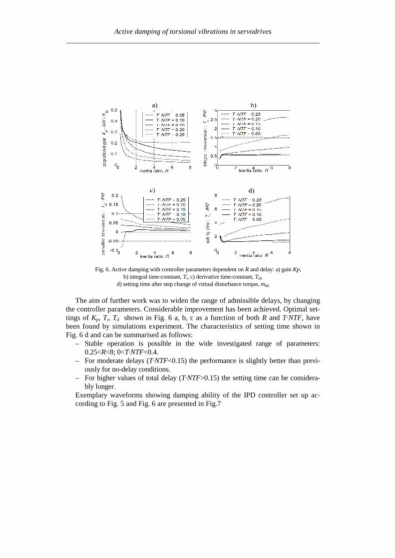
Active damping of torsional vibrations in servodrives_____________________________________________________________________
Fig 6 Active damping with controller parameters dependent on R and delay a) gain Kpb) integral time-constant Ti c) derivative time-constant TD
d) setting time after step change of virtual disturbance torque mdd
The aim of further work was to widen the range of admissible delays by changingthe controller parameters Considerable improvement has been achieved Optimal set-tings of Kp Ti Td shown in Fig 6 a b c as a function of both R and TmiddotNTF havebeen found by simulations experiment The characteristics of setting time shown inFig 6 d and can be summarised as follows
ndash Stable operation is possible in the wide investigated range of parameters025ltRlt8 0ltTmiddotNTFlt04
ndash For moderate delays (TmiddotNTFlt015) the performance is slightly better than previ-ously for no-delay conditions
ndash For higher values of total delay (TmiddotNTFgt015) the setting time can be considera-bly longer
Exemplary waveforms showing damping ability of the IPD controller set up ac-cording to Fig 5 and Fig 6 are presented in Fig7
Active damping of torsional vibrations in servodrives_____________________________________________________________________
4 STATE CONTROLLER WITH STATE OBSERVER
41 STRUCTURE OF THE SYSTEM
The state controller is one of the classical solutions of the control task It is oftenused also for the systems with flexibility [1] [2] [3] [12] and [20] According to as-sumption of this work many structures of the system with state controller intended forhigh power drives should be rejected because of additional sensors installed on the loadside The structure using only the position encoder integrated with the motor is shown inFig 8 There are elements of digital processing (sampler differentiation procedure) ofposition signal in the feedback path of the model They introduce to the path the delay Tf
equal to the time step Ts of the DSP controller Other blocks in the model are simulatedin continuous-time domain Their delays are included to the block modelling torquecontrol loop (total delay Tg of the block)
The state controller uses the signals of motor mM and shaft shm torque as well as
motor ωMd and load Lω speed The feedback from signal mM is easy to realise as themotor torque is usually proportional to the current (whose signal is measurable) In somecases the reference torque mr can be used instead of motor torque mM This solution cor-
responds to the controller shown in Fig 3 In order to have the signals shm and Lω thecontroller algorithm must realise also observer procedure In frame of presented on
Fig 8 controller it is also possible to test system without internal feedback signal shm or
Lω
Fig7 Waveforms of motor speed ωM and load speed ωL as responses on step change of reference
speed ωrd and following step change of signal mdd a) with controller set up according to [21] and
Fig5 a b) with proposed settings according to Fig 6 (R=2 TmiddotNTF=011)
Active damping of torsional vibrations in servodrives_____________________________________________________________________
z
11minus
sT
1 θMd
Differentiation Sampler
Quantiser
Digital processing delay Tf = Ts
Statecontroller
gsTeminus
2-masssystem(fig 2)
θM
mL
mM
Torque control loop inclu-ding additional delay
mr
Stateobserver
shm
Lω
ωMd
ωr
mM bull
bull
bull
Fig 8 Model of the system with state controller and state observer
42 THE STATE CONTROLLER
The linear state controller operates according to the equation
LLshshMdMMmrr ωkmkωkmkωkm minusminusminusminus= ω (12)
where the gains of component with reference motor and load speed should fulfil therelation
LM kkk +=ω (13)
in order to have no load operation without speed error Therefore if
ωkakM sdot= (14)
then
( ) ωkakL sdotminus= 1 (15)
Active damping of torsional vibrations in servodrives_____________________________________________________________________
where the a is the weight of the motor speed feedback and 1ndasha is the weight of the loadspeed feedback The coefficients kω a km and ksh are the parameters of the controllerinfluencing the properties of the system These parameters are selected using optimisa-tion procedure as described in subchapter 44
Instead of the linear state controller the non-linear one described in [16] can be usedIt should give further improving the properties also in the systems with delay
43 THE STATE OBSERVER
The observer (Fig 9) contains the two-mass model (Fig 2) and correction elements
Reduction of the error between the motor speed ωMd and speed Mω from the observer tothe value near by zero allows reproducing the signals of the load speed ωL and shafttorque msh A quality of it depends on the gains h1 h4 In order to reproduce the loadtorque mL the error of the observation of motor speed is integrated in the circuit with thegain h4
The signal Lm can be used in the observer for compensation of the speed drop due to
loading the drive For this purpose the signal Lm should be introduced to the torquesumming point (dashed line in the Fig 9) with positive gain hL The principle of thiscompensation is given in [10] together with derivation of the following condition
m
shL k
kh
++=
11 (16)
at which the speed is invariant with regard to loading
44 RESULTS OF THE PRELIMINARY SIMULATION
Preliminary the system from Fig 8 was simulated without the observer i eksh=kL=0 and a = 1 The inertia ratio was R = 1 During investigation the total delay Twas varied Every time the T was divided in two parts Tg = 2T3 and Tf = T3 Themaximum value of index TNTF was searched at which the controller is able active todamp the oscillations For each value of delay the gains kω and km of the controller wereoptimised The maximum ratio of two successive amplitudes of the oscillating quantitieswas the optimisation criterion
The results of the simulation are given in Table 1 It is seen that with increase ofstiffness (delay) the optimum value of feedback gains decrease Simultaneously the set-ting time becomes longer State controller having only motor speed and motor torque
Active damping of torsional vibrations in servodrives_____________________________________________________________________
Fig 9 The state observer
feedback paths is able to damp the oscillation in the system with stiffness up to about023 (the highest value in the Table 1)
A better result is expected after additionally feeding the controller from the observerwith the feedback signals of the shaft torque and load speed However the degree ofimprovement of system properties will depend strongly on encoder inaccuracy and alsoon delay as the observer uses non-actual values of the quantities
Table 1 The dependence of the controller parameters and setting time on thestiffness factor for the system with state controller having only two feedback paths
Stiffness factorTNTF 0101 0135 0169 0230
kω [Nsrad] 1 0556 0333 0133Controllerparameters km [-] 1 0667 0333 0167
Setting time multipliedby the ARF 113 163 424 very long
The controller parameters are relate to first data column
Active damping of torsional vibrations in servodrives_____________________________________________________________________
5 SLOW RESONANCE RATIO CONTROLLER
The slow resonance ratio control (SRRC) was firstly introduced as a method forvibration suppression and disturbance rejection in torsional systems [1] [6] [7]SRRC algorithm feeds back the torsional torque estimated by a model-based distur-bance observer so to change the virtual motor inertia to an arbitrary selected valueThis means that the resonance frequency NTF and then the resonance ratioH=NTFARF can be changed
Fig 2e-sT
JM
1-K
Differential
2DOF PI
LPF(Tq)LPF(Tq)
Differential
K+
++-
+-
digital speed controllerωrd
ωMd θMd
θM
mrd
mM
mL
mr
samplerquantizer
torque control loopand additional delay
2-mass systemextrapolator
msh^
Fig 10 Block diagram of resonance control
The detail of the resonance ratio control with shaft torque observer is reported inFig 10 where the mechanical model from Fig 2 has been used The digital speedcontrollerrsquos model has been simplified by fusion all delays in the closed loop torquecontrol Based on measurement motor speed ωMd and reference torque mrd the shaft
torque shm is estimated Only (1-K) portion of the estimated shaft torque is fed backBy doing this the designed virtual motor inertia JM-des is defined as
KJJ MdesM =minus (17)
This means that virtual inertia ratio Rdes can be expressed as
KRJJR LdesMdes sdot== minus (18)
Active damping of torsional vibrations in servodrives_____________________________________________________________________
The resonance ratio H could be changed to value desdes RH += 1
The slow disturbance observer was originally proposed by Iwata and Itoh [8]They proposed that the optimal cut-off frequency should be a little lower than theanti-resonant frequency ARF The optimal observer time constant Tq is calculated onbasis R and Rdes as given by [17]
ARFRRRR
RR
Tdesdes
des
q sdotsdot
++
++
++=
π21
21
43
1
4
31
When PI speed controller is used the characteristic equation of the closed drive sys-tem is
01
12
23
34
4)( asasasasasP ++++= (19)
The coefficients a4ndasha0 can be selected according to desired dynamical propertiesof whole system The effective method is Coefficient Diagram Method based on Ma-nabe polynomials [15] In this method design specifications are equivalent time con-stant (τ ) and stability indices (γi) For analysed system τ is defined as
01 aa=τ (20)
and stability indices should be selected as follow
2 2 5242
23
331
22
220
21
1 ======aa
a
aa
a
aa
a γγγ (21)
By solving these equations the optimal resonance ratio can be determined
580 sdot=desH This correspond to inertia ratio Rdes=115
From (18) the coefficient K is calculated The controller gains are given by (com-pare [7])
22
)(11
1611
220
ARFJK
ARFJK
Li
Lp
sdotsdotsdot=
sdotsdotsdot=
π
π
(22)
Active damping of torsional vibrations in servodrives_____________________________________________________________________
Simulation experiments has been carried out to find the range of stabile parameters atwhich presented SRRC could be used The results of this investigation can be summa-rised as followsStability boundary
- TmiddotNTF gt 012 for 08 lt R lt 2- TmiddotNTF gt 010 for 08 lt R lt 8- TmiddotNTF gt 003 for 035 lt R lt 8
Setting time Tω - ARF Tω lt18 for TmiddotNTF = 01 and 08 lt R lt 2- ARF Tω lt42 for TmiddotNTF = 008 and 2 lt R lt 8- ARF Tω lt51 for TmiddotNTF = 006 and 05 lt R lt 1
Presented slow resonance ratio controller is well fitting for system with relativelarge load inertia in relation to motor inertia In such case the virtual motor inertia isincreasing through using feedback coefficient K smaller than 1 and the whole systemis robust to real-time delays However if the load inertia is small feedback coeffi-cient K greater than 1 is needed and system is sensitive to any time lags It should benoted that when the motor inertia is much larger than the load inertia the resonanceratio control makes the disturbance response worse This fact suggests that the vibra-tion suppression and the disturbance rejection are opposite objectives [7]
6 LINEAR-QUADRATIC CONTROLLER WITH KALMAN FILTER
61 STATE AND DISTURBANCES OBSERVER
When using the LQ-controller state vector should be available State variables thatcannot be measured should be estimated
The Kalman Filter is one of proposed estimators [11] [12] [13] [17] Kalmanfilter theory allows estimating all state variables Theory presented in [11] determinesthe state variables They could be disturbed by Gaussian white noise which repre-sents all error sources and model inaccuracy [11] This is a narrow assumption thathas been avoided in his work This causes difficulties with theoretical tuning rules
Basing on filtering knowledge [11] the model of the system can be expressed bystate (23) and measurement (24) equations
1n e n e n nx x u w+ = + +A B (23)
n e n ny x v= +C (24)
Active damping of torsional vibrations in servodrives_____________________________________________________________________
where the control signal u is equal to the torque command mr and the output vector yis equal to mechanical position θ In equations (23) and (24) w represents a processnoise and v - measurement noise
It is assumed that the disturbing load torque (mL) is a part of measurement noiseand a part of state vector The assumption is only valid when the derivative of loadtorque is near to zero
0L
dm
dtasymp (25)
The state vector of observer has been extended by new estimated variable (Lm )
ˆˆ ˆˆ ˆ ˆT
M L sh Lx m mω ω θ = (26)
New state space matrices are equal
10 0 0 0
1 10 0 0
0 0 0
0 0 0 0 0
1 0 0 0 0
M
L Le
sh sh
J
J J
K K
minus minus =
minus
A
=
0
0
0
0
1
M
e
J
B
0
0
0
0
1
e
=
C (272829)
The equations of estimator are given by
( )| | 1 | 1
1| |
ˆ ˆ ˆ
ˆ ˆ ˆ
n n n n e n e n n
n n e n n e n
x x y x
x x u
minus minus
+
= + minus
= +
K C
A B (30)
where Ke is a Kalman filter gains which is computed by solving Ricatti equation[11] The gains can be calculated using recursive algorithm only one time and can bevalid for each step of control algorithm The noisersquos covariance of presented system(025ltRlt8 Ksh=1 equivalent of 14bit encoder) can be determine by matrix Qe
Active damping of torsional vibrations in servodrives_____________________________________________________________________
22
14
202 02 10 10
2e diag π =
Q (31)
which values represent covariances respectively with vector x elements The noisersquoscovariance of output signal may be described by
2
e 14
2
2R
π =
(32)
Theoretically the appropriate values should be real covariance but they was se-lected experimentally during system investigations It is noticed that last element ofQe matrix and Re is linked with the one known error It is caused by the quantisationduring obtaining real position from the 14-bit encoder
62 LQ CONTROL STRATEGY
The LQ-controller has several good properties [4] [9] and [18] It is applicable tomultivariable and time-varying systems when a model of the system can be availablein state space form (Fig 11) Changing the relations between the magnitude of ele-ments in weighting matrices we obtain compromise between the control speed and themagnitudes of control signals
Fig 11 Model of the system with LQ-controller and Kalman filter
The finding of answer presented in [9] is applicable to our system The generalformulation of the problem is to minimise the performance index J The following
Active damping of torsional vibrations in servodrives_____________________________________________________________________
deviations from steady state has been defined ∆x ∆u (for state and control variablesrespectively) The designed problem was reformulated to LQ-compensator with newdefined performance index J
( ) ( )( )2
0
T
r rJ R ux xinfin
= + ∆∆ ∆int Q (33)
where Qr and Rr are defined tuning matricesIn state controller the control-input signal is given by follows
r
xu
p
= minus
K (34)
Partitioning Kr and using integral control to cancel steady-state error
( )0
ˆt
M rdp dtω ω= minusint (35)
the control input signal yields
[ ] ( )1 2 3
0
ˆ
ˆ ˆ
ˆ
M t
L p M rd
sh
u K K K K dt
m
ωω ω ω = minus minus minus
int (36)
The main problem during solving LQ regulator is proper choosing the performanceindex J As shown in [9] Qr and Rr are given as
0 0
0 0
0 0 0 0
0 0 0
r
α αα α β
δ
minus minus + =
Q rR ε= (3738)
Performance index (33) can be expressed in more practical form
Active damping of torsional vibrations in servodrives_____________________________________________________________________
( ) ( )( ) ( )
2 2
2 20
M L L Ls
s s
J dtp p u u
α ω ω β ω ω
δ ε
infin minus + minus + = + minus + minus
int (39)
where Greek symbols mark weighting for α ndash torsional vibration suppression
β ndash command following δ ndash steady-state error ε ndash control input
The weight factors were selected experimentally α = 1 β = 100 δ = 100 ε = 01
63 SIMULATION RESULTS
Simulation experiments confirmed that there exists a range of delay at which theLQ-controller using signals dealt by Kalman filter can be constructed The wholesystem has been experimentally tuned (without any optimisation) to check how thetotal delay T influences system performance The preliminary results of investigationcan be briefly formulated as follows
ndash Delay TsdotNTF lt 008 has very small influence on system performance
ndash The setting time without delay is ARFsdotTω asymp 2 Similar performance can be ob-
tained for increasing delay only in limited range of inertia ratio
ndash TsdotNTF lt 008 and 025ltRlt05
ndash TsdotNTF lt 011 and R=1
ndash TsdotNTF lt 02 and 2 lt R lt 8
ndash When TsdotNTF lt 035 the system is stable but the setting time is unacceptable
large
7 CONCLUSION
It is possible to actively damp torsional vibration using single feedback signal fromencoder only Damping ability depends on the inertia ratio R and total delay T in thespeed control loop Because single feedback signal is considered and the controllerhas single output all analysed controllers can be treated as digital filters Apart fromvarious internal descriptions all controllers actually differ only in filter order and co-efficients Methods of calculation and tuning controller gains (or filter coefficients)are also different Unfortunately no systematic design methods have been found forthe analysed controllers Only heuristic approach for controller tuning was tested Themost complete and most promising results have been obtained for the unconventional
Active damping of torsional vibrations in servodrives_____________________________________________________________________
IPD controllers The near-optimum parameters have been found by simulation ex-periments for wide range of R and T These parameters can be directly applied in realPID controlled industrial drives
Another considered methods have been elaborated only partially Because theyconstitute filters of higher order than simple PI-controller probably better resultscould be obtained This possible advantage has not been fully confirmed in this workAuthors concentrate on practical rules for choosing suitable parameters of state con-troller and observer as well as gains of Kalman filter and LQ compensator
ACKONWLEDGEMENT
This work was partially supported by the grant 3 T10A 026 28
REFERENCES
[1] BOLOGNANI S VENTURATO A ZIGLIOTTO M Theoretical and experimental comparisonof speed controllers for elastic two-mass-systems Proc31st APESCrsquo2000 vol 3 pp1087-10922000
[2] DEUR J PERIC N Analysis of speed control system for electrical drives with elastic transmissionProc of the IEEE Int Symp ISIErsquo99 Bled Slovenia vol 2 pp 624-630 1999
[3] DEUR J PERIC N Pointing and tracking position control system for electrical drives with elastictransmission Proc 9th Int Conf PEMCrsquo2000 Kosice Slovak Republic pp7-1-7-6 2000
[4] FRANKLIN GF POWELL JD WORKMAN ML Digital Control of Dynamic Systems 3rdEdition Prentice Hall 1997
[5] GIERLOTKA K ZALEŚNY P Metoda obliczania parametroacutew układu regulacji napędu z połą-czeniem spręŜystym z dodatkowymi sprzęŜeniami zwrotnymi ZN Politechniki Śląskiej Elektrykaz170 (1999) str 65-72
[6] HORI Y SAWADA H CHUN Y Slow Resonance Ratio Control for Vibration Suppression andDisturbance Rejection in Torsional System IEEE Trans on Industrial Electronics vol 34 pp 162-168 1999
[7] HORI Y Comparison of Torsional Vibration Controls based on the Fast and Slow DisturbanceObservers Proc Int Conf IPEC95 Vol1 pp440-446 Yokohama 1995
[8] IWATA M ITOH S High Performance and Adaptive Motion Control System Based on IdentifiedMechanical Parameter Proc 3rd Int Workshop on Advanced Motion Control 1994 Berkeley
[9] JI J-K SUL S-K Kalman filter and LQ based speed controller for torsional vibration suppres-sion in a 2-mass motor drive system IEEE Trans Ind Electron vol 42 no 6 pp564ndash571 1995
[10] KALEJTA T MUSZYŃSKI R State observer for servodrive with flexibility Proc 4th Int SympELECTROMOTION`01 Bologna Italy vol 1 pp 159-164 2001
[11] KALMAN RE New Approach to Linear Filtering and Prediction Problems Trans of the ASMEJournal of Basic Engineering 1960 pp 374-382
[12] ORŁOWSKA-KOWALSKA T SZABAT K Zastosowanie regulatora stanu w układzie napędo-wym z połączeniem spręŜystym MaterVI Kraj Konf SENE 2003 tom III pp 679-685
[13] ORŁOWSKA-KOWALSKA T SZABAT K State Feedback Control of Two-Mass System withState Estimator Proc Int ConfEDPErsquo2003 Hihg Tatras Slovak Rep pp 590-595 2003
[14] ORŁOWSKA-KOWALSKA T SZABAT K Optimization of fuzzy-logic speed controller for DC
Active damping of torsional vibrations in servodrives_____________________________________________________________________
drive system with elastic joints IEEE Trans on Ind Applic vol 40 no 4 pp1138-1144 2004[15] MANABE S Coefficient Diagram Method Proc 14th IFAC Symp on Automatic Control in Aero-
space Seoul1998[16] MUSZYŃSKI R KACZMAREK T The elastic servo drive with state controller Archives of
Electrical Engineering vol LII no 2 pp 185-200 2003[17] SHIN D-J HUH U-Y Robust motion controller design for servo system with 2 mass characteris-
tics Proc 6th Inter Workshop on Advanced Motion Control 2000 pp 423-426[18] STEFANI R SAVANT C SHAHIAN B HOSTETTER G Design of Feedback Control Systems
Saunders College Publisher 1994[19] SZABAT K ORŁOWSKA-KOWALSKA T Tłumienie oscylacji prędkości w układzie napędowym
z połaczeniem spręŜystym Przegląd Elektrotechniczny vol LXXIX no 7-8 pp 474-482 2003[20] ШИЯНОВ А И МЕДВЕДЕВ ΒАМОРОЗОВ СВ Асинхронный злектропривод с упругой
нагрузкой и адаптивным регулятором ЗЛЕКТРИЧЕСТВО no 2 pp47divide49 2001[21] ZHANG G FURUSHO J Speed Control of Two-Inertia System by PIPID control IEEE Trans on
Industrial Electronics vol 47 no3 pp 603-609 2000
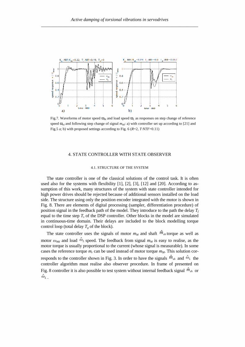
Active damping of torsional vibrations in servodrives_____________________________________________________________________
z
11minus
sT
1 θMd
Differentiation Sampler
Quantiser
Digital processing delay Tf = Ts
Statecontroller
gsTeminus
2-masssystem(fig 2)
θM
mL
mM
Torque control loop inclu-ding additional delay
mr
Stateobserver
shm
Lω
ωMd
ωr
mM bull
bull
bull
Fig 8 Model of the system with state controller and state observer
42 THE STATE CONTROLLER
The linear state controller operates according to the equation
LLshshMdMMmrr ωkmkωkmkωkm minusminusminusminus= ω (12)
where the gains of component with reference motor and load speed should fulfil therelation
LM kkk +=ω (13)
in order to have no load operation without speed error Therefore if
ωkakM sdot= (14)
then
( ) ωkakL sdotminus= 1 (15)
Active damping of torsional vibrations in servodrives_____________________________________________________________________
where the a is the weight of the motor speed feedback and 1ndasha is the weight of the loadspeed feedback The coefficients kω a km and ksh are the parameters of the controllerinfluencing the properties of the system These parameters are selected using optimisa-tion procedure as described in subchapter 44
Instead of the linear state controller the non-linear one described in [16] can be usedIt should give further improving the properties also in the systems with delay
43 THE STATE OBSERVER
The observer (Fig 9) contains the two-mass model (Fig 2) and correction elements
Reduction of the error between the motor speed ωMd and speed Mω from the observer tothe value near by zero allows reproducing the signals of the load speed ωL and shafttorque msh A quality of it depends on the gains h1 h4 In order to reproduce the loadtorque mL the error of the observation of motor speed is integrated in the circuit with thegain h4
The signal Lm can be used in the observer for compensation of the speed drop due to
loading the drive For this purpose the signal Lm should be introduced to the torquesumming point (dashed line in the Fig 9) with positive gain hL The principle of thiscompensation is given in [10] together with derivation of the following condition
m
shL k
kh
++=
11 (16)
at which the speed is invariant with regard to loading
44 RESULTS OF THE PRELIMINARY SIMULATION
Preliminary the system from Fig 8 was simulated without the observer i eksh=kL=0 and a = 1 The inertia ratio was R = 1 During investigation the total delay Twas varied Every time the T was divided in two parts Tg = 2T3 and Tf = T3 Themaximum value of index TNTF was searched at which the controller is able active todamp the oscillations For each value of delay the gains kω and km of the controller wereoptimised The maximum ratio of two successive amplitudes of the oscillating quantitieswas the optimisation criterion
The results of the simulation are given in Table 1 It is seen that with increase ofstiffness (delay) the optimum value of feedback gains decrease Simultaneously the set-ting time becomes longer State controller having only motor speed and motor torque
Active damping of torsional vibrations in servodrives_____________________________________________________________________
Fig 9 The state observer
feedback paths is able to damp the oscillation in the system with stiffness up to about023 (the highest value in the Table 1)
A better result is expected after additionally feeding the controller from the observerwith the feedback signals of the shaft torque and load speed However the degree ofimprovement of system properties will depend strongly on encoder inaccuracy and alsoon delay as the observer uses non-actual values of the quantities
Table 1 The dependence of the controller parameters and setting time on thestiffness factor for the system with state controller having only two feedback paths
Stiffness factorTNTF 0101 0135 0169 0230
kω [Nsrad] 1 0556 0333 0133Controllerparameters km [-] 1 0667 0333 0167
Setting time multipliedby the ARF 113 163 424 very long
The controller parameters are relate to first data column
Active damping of torsional vibrations in servodrives_____________________________________________________________________
5 SLOW RESONANCE RATIO CONTROLLER
The slow resonance ratio control (SRRC) was firstly introduced as a method forvibration suppression and disturbance rejection in torsional systems [1] [6] [7]SRRC algorithm feeds back the torsional torque estimated by a model-based distur-bance observer so to change the virtual motor inertia to an arbitrary selected valueThis means that the resonance frequency NTF and then the resonance ratioH=NTFARF can be changed
Fig 2e-sT
JM
1-K
Differential
2DOF PI
LPF(Tq)LPF(Tq)
Differential
K+
++-
+-
digital speed controllerωrd
ωMd θMd
θM
mrd
mM
mL
mr
samplerquantizer
torque control loopand additional delay
2-mass systemextrapolator
msh^
Fig 10 Block diagram of resonance control
The detail of the resonance ratio control with shaft torque observer is reported inFig 10 where the mechanical model from Fig 2 has been used The digital speedcontrollerrsquos model has been simplified by fusion all delays in the closed loop torquecontrol Based on measurement motor speed ωMd and reference torque mrd the shaft
torque shm is estimated Only (1-K) portion of the estimated shaft torque is fed backBy doing this the designed virtual motor inertia JM-des is defined as
KJJ MdesM =minus (17)
This means that virtual inertia ratio Rdes can be expressed as
KRJJR LdesMdes sdot== minus (18)
Active damping of torsional vibrations in servodrives_____________________________________________________________________
The resonance ratio H could be changed to value desdes RH += 1
The slow disturbance observer was originally proposed by Iwata and Itoh [8]They proposed that the optimal cut-off frequency should be a little lower than theanti-resonant frequency ARF The optimal observer time constant Tq is calculated onbasis R and Rdes as given by [17]
ARFRRRR
RR
Tdesdes
des
q sdotsdot
++
++
++=
π21
21
43
1
4
31
When PI speed controller is used the characteristic equation of the closed drive sys-tem is
01
12
23
34
4)( asasasasasP ++++= (19)
The coefficients a4ndasha0 can be selected according to desired dynamical propertiesof whole system The effective method is Coefficient Diagram Method based on Ma-nabe polynomials [15] In this method design specifications are equivalent time con-stant (τ ) and stability indices (γi) For analysed system τ is defined as
01 aa=τ (20)
and stability indices should be selected as follow
2 2 5242
23
331
22
220
21
1 ======aa
a
aa
a
aa
a γγγ (21)
By solving these equations the optimal resonance ratio can be determined
580 sdot=desH This correspond to inertia ratio Rdes=115
From (18) the coefficient K is calculated The controller gains are given by (com-pare [7])
22
)(11
1611
220
ARFJK
ARFJK
Li
Lp
sdotsdotsdot=
sdotsdotsdot=
π
π
(22)
Active damping of torsional vibrations in servodrives_____________________________________________________________________
Simulation experiments has been carried out to find the range of stabile parameters atwhich presented SRRC could be used The results of this investigation can be summa-rised as followsStability boundary
- TmiddotNTF gt 012 for 08 lt R lt 2- TmiddotNTF gt 010 for 08 lt R lt 8- TmiddotNTF gt 003 for 035 lt R lt 8
Setting time Tω - ARF Tω lt18 for TmiddotNTF = 01 and 08 lt R lt 2- ARF Tω lt42 for TmiddotNTF = 008 and 2 lt R lt 8- ARF Tω lt51 for TmiddotNTF = 006 and 05 lt R lt 1
Presented slow resonance ratio controller is well fitting for system with relativelarge load inertia in relation to motor inertia In such case the virtual motor inertia isincreasing through using feedback coefficient K smaller than 1 and the whole systemis robust to real-time delays However if the load inertia is small feedback coeffi-cient K greater than 1 is needed and system is sensitive to any time lags It should benoted that when the motor inertia is much larger than the load inertia the resonanceratio control makes the disturbance response worse This fact suggests that the vibra-tion suppression and the disturbance rejection are opposite objectives [7]
6 LINEAR-QUADRATIC CONTROLLER WITH KALMAN FILTER
61 STATE AND DISTURBANCES OBSERVER
When using the LQ-controller state vector should be available State variables thatcannot be measured should be estimated
The Kalman Filter is one of proposed estimators [11] [12] [13] [17] Kalmanfilter theory allows estimating all state variables Theory presented in [11] determinesthe state variables They could be disturbed by Gaussian white noise which repre-sents all error sources and model inaccuracy [11] This is a narrow assumption thathas been avoided in his work This causes difficulties with theoretical tuning rules
Basing on filtering knowledge [11] the model of the system can be expressed bystate (23) and measurement (24) equations
1n e n e n nx x u w+ = + +A B (23)
n e n ny x v= +C (24)
Active damping of torsional vibrations in servodrives_____________________________________________________________________
where the control signal u is equal to the torque command mr and the output vector yis equal to mechanical position θ In equations (23) and (24) w represents a processnoise and v - measurement noise
It is assumed that the disturbing load torque (mL) is a part of measurement noiseand a part of state vector The assumption is only valid when the derivative of loadtorque is near to zero
0L
dm
dtasymp (25)
The state vector of observer has been extended by new estimated variable (Lm )
ˆˆ ˆˆ ˆ ˆT
M L sh Lx m mω ω θ = (26)
New state space matrices are equal
10 0 0 0
1 10 0 0
0 0 0
0 0 0 0 0
1 0 0 0 0
M
L Le
sh sh
J
J J
K K
minus minus =
minus
A
=
0
0
0
0
1
M
e
J
B
0
0
0
0
1
e
=
C (272829)
The equations of estimator are given by
( )| | 1 | 1
1| |
ˆ ˆ ˆ
ˆ ˆ ˆ
n n n n e n e n n
n n e n n e n
x x y x
x x u
minus minus
+
= + minus
= +
K C
A B (30)
where Ke is a Kalman filter gains which is computed by solving Ricatti equation[11] The gains can be calculated using recursive algorithm only one time and can bevalid for each step of control algorithm The noisersquos covariance of presented system(025ltRlt8 Ksh=1 equivalent of 14bit encoder) can be determine by matrix Qe
Active damping of torsional vibrations in servodrives_____________________________________________________________________
22
14
202 02 10 10
2e diag π =
Q (31)
which values represent covariances respectively with vector x elements The noisersquoscovariance of output signal may be described by
2
e 14
2
2R
π =
(32)
Theoretically the appropriate values should be real covariance but they was se-lected experimentally during system investigations It is noticed that last element ofQe matrix and Re is linked with the one known error It is caused by the quantisationduring obtaining real position from the 14-bit encoder
62 LQ CONTROL STRATEGY
The LQ-controller has several good properties [4] [9] and [18] It is applicable tomultivariable and time-varying systems when a model of the system can be availablein state space form (Fig 11) Changing the relations between the magnitude of ele-ments in weighting matrices we obtain compromise between the control speed and themagnitudes of control signals
Fig 11 Model of the system with LQ-controller and Kalman filter
The finding of answer presented in [9] is applicable to our system The generalformulation of the problem is to minimise the performance index J The following
Active damping of torsional vibrations in servodrives_____________________________________________________________________
deviations from steady state has been defined ∆x ∆u (for state and control variablesrespectively) The designed problem was reformulated to LQ-compensator with newdefined performance index J
( ) ( )( )2
0
T
r rJ R ux xinfin
= + ∆∆ ∆int Q (33)
where Qr and Rr are defined tuning matricesIn state controller the control-input signal is given by follows
r
xu
p
= minus
K (34)
Partitioning Kr and using integral control to cancel steady-state error
( )0
ˆt
M rdp dtω ω= minusint (35)
the control input signal yields
[ ] ( )1 2 3
0
ˆ
ˆ ˆ
ˆ
M t
L p M rd
sh
u K K K K dt
m
ωω ω ω = minus minus minus
int (36)
The main problem during solving LQ regulator is proper choosing the performanceindex J As shown in [9] Qr and Rr are given as
0 0
0 0
0 0 0 0
0 0 0
r
α αα α β
δ
minus minus + =
Q rR ε= (3738)
Performance index (33) can be expressed in more practical form
Active damping of torsional vibrations in servodrives_____________________________________________________________________
( ) ( )( ) ( )
2 2
2 20
M L L Ls
s s
J dtp p u u
α ω ω β ω ω
δ ε
infin minus + minus + = + minus + minus
int (39)
where Greek symbols mark weighting for α ndash torsional vibration suppression
β ndash command following δ ndash steady-state error ε ndash control input
The weight factors were selected experimentally α = 1 β = 100 δ = 100 ε = 01
63 SIMULATION RESULTS
Simulation experiments confirmed that there exists a range of delay at which theLQ-controller using signals dealt by Kalman filter can be constructed The wholesystem has been experimentally tuned (without any optimisation) to check how thetotal delay T influences system performance The preliminary results of investigationcan be briefly formulated as follows
ndash Delay TsdotNTF lt 008 has very small influence on system performance
ndash The setting time without delay is ARFsdotTω asymp 2 Similar performance can be ob-
tained for increasing delay only in limited range of inertia ratio
ndash TsdotNTF lt 008 and 025ltRlt05
ndash TsdotNTF lt 011 and R=1
ndash TsdotNTF lt 02 and 2 lt R lt 8
ndash When TsdotNTF lt 035 the system is stable but the setting time is unacceptable
large
7 CONCLUSION
It is possible to actively damp torsional vibration using single feedback signal fromencoder only Damping ability depends on the inertia ratio R and total delay T in thespeed control loop Because single feedback signal is considered and the controllerhas single output all analysed controllers can be treated as digital filters Apart fromvarious internal descriptions all controllers actually differ only in filter order and co-efficients Methods of calculation and tuning controller gains (or filter coefficients)are also different Unfortunately no systematic design methods have been found forthe analysed controllers Only heuristic approach for controller tuning was tested Themost complete and most promising results have been obtained for the unconventional
Active damping of torsional vibrations in servodrives_____________________________________________________________________
IPD controllers The near-optimum parameters have been found by simulation ex-periments for wide range of R and T These parameters can be directly applied in realPID controlled industrial drives
Another considered methods have been elaborated only partially Because theyconstitute filters of higher order than simple PI-controller probably better resultscould be obtained This possible advantage has not been fully confirmed in this workAuthors concentrate on practical rules for choosing suitable parameters of state con-troller and observer as well as gains of Kalman filter and LQ compensator
ACKONWLEDGEMENT
This work was partially supported by the grant 3 T10A 026 28
REFERENCES
[1] BOLOGNANI S VENTURATO A ZIGLIOTTO M Theoretical and experimental comparisonof speed controllers for elastic two-mass-systems Proc31st APESCrsquo2000 vol 3 pp1087-10922000
[2] DEUR J PERIC N Analysis of speed control system for electrical drives with elastic transmissionProc of the IEEE Int Symp ISIErsquo99 Bled Slovenia vol 2 pp 624-630 1999
[3] DEUR J PERIC N Pointing and tracking position control system for electrical drives with elastictransmission Proc 9th Int Conf PEMCrsquo2000 Kosice Slovak Republic pp7-1-7-6 2000
[4] FRANKLIN GF POWELL JD WORKMAN ML Digital Control of Dynamic Systems 3rdEdition Prentice Hall 1997
[5] GIERLOTKA K ZALEŚNY P Metoda obliczania parametroacutew układu regulacji napędu z połą-czeniem spręŜystym z dodatkowymi sprzęŜeniami zwrotnymi ZN Politechniki Śląskiej Elektrykaz170 (1999) str 65-72
[6] HORI Y SAWADA H CHUN Y Slow Resonance Ratio Control for Vibration Suppression andDisturbance Rejection in Torsional System IEEE Trans on Industrial Electronics vol 34 pp 162-168 1999
[7] HORI Y Comparison of Torsional Vibration Controls based on the Fast and Slow DisturbanceObservers Proc Int Conf IPEC95 Vol1 pp440-446 Yokohama 1995
[8] IWATA M ITOH S High Performance and Adaptive Motion Control System Based on IdentifiedMechanical Parameter Proc 3rd Int Workshop on Advanced Motion Control 1994 Berkeley
[9] JI J-K SUL S-K Kalman filter and LQ based speed controller for torsional vibration suppres-sion in a 2-mass motor drive system IEEE Trans Ind Electron vol 42 no 6 pp564ndash571 1995
[10] KALEJTA T MUSZYŃSKI R State observer for servodrive with flexibility Proc 4th Int SympELECTROMOTION`01 Bologna Italy vol 1 pp 159-164 2001
[11] KALMAN RE New Approach to Linear Filtering and Prediction Problems Trans of the ASMEJournal of Basic Engineering 1960 pp 374-382
[12] ORŁOWSKA-KOWALSKA T SZABAT K Zastosowanie regulatora stanu w układzie napędo-wym z połączeniem spręŜystym MaterVI Kraj Konf SENE 2003 tom III pp 679-685
[13] ORŁOWSKA-KOWALSKA T SZABAT K State Feedback Control of Two-Mass System withState Estimator Proc Int ConfEDPErsquo2003 Hihg Tatras Slovak Rep pp 590-595 2003
[14] ORŁOWSKA-KOWALSKA T SZABAT K Optimization of fuzzy-logic speed controller for DC
Active damping of torsional vibrations in servodrives_____________________________________________________________________
drive system with elastic joints IEEE Trans on Ind Applic vol 40 no 4 pp1138-1144 2004[15] MANABE S Coefficient Diagram Method Proc 14th IFAC Symp on Automatic Control in Aero-
space Seoul1998[16] MUSZYŃSKI R KACZMAREK T The elastic servo drive with state controller Archives of
Electrical Engineering vol LII no 2 pp 185-200 2003[17] SHIN D-J HUH U-Y Robust motion controller design for servo system with 2 mass characteris-
tics Proc 6th Inter Workshop on Advanced Motion Control 2000 pp 423-426[18] STEFANI R SAVANT C SHAHIAN B HOSTETTER G Design of Feedback Control Systems
Saunders College Publisher 1994[19] SZABAT K ORŁOWSKA-KOWALSKA T Tłumienie oscylacji prędkości w układzie napędowym
z połaczeniem spręŜystym Przegląd Elektrotechniczny vol LXXIX no 7-8 pp 474-482 2003[20] ШИЯНОВ А И МЕДВЕДЕВ ΒАМОРОЗОВ СВ Асинхронный злектропривод с упругой
нагрузкой и адаптивным регулятором ЗЛЕКТРИЧЕСТВО no 2 pp47divide49 2001[21] ZHANG G FURUSHO J Speed Control of Two-Inertia System by PIPID control IEEE Trans on
Industrial Electronics vol 47 no3 pp 603-609 2000
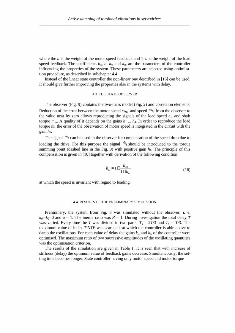
Active damping of torsional vibrations in servodrives_____________________________________________________________________
where the a is the weight of the motor speed feedback and 1ndasha is the weight of the loadspeed feedback The coefficients kω a km and ksh are the parameters of the controllerinfluencing the properties of the system These parameters are selected using optimisa-tion procedure as described in subchapter 44
Instead of the linear state controller the non-linear one described in [16] can be usedIt should give further improving the properties also in the systems with delay
43 THE STATE OBSERVER
The observer (Fig 9) contains the two-mass model (Fig 2) and correction elements
Reduction of the error between the motor speed ωMd and speed Mω from the observer tothe value near by zero allows reproducing the signals of the load speed ωL and shafttorque msh A quality of it depends on the gains h1 h4 In order to reproduce the loadtorque mL the error of the observation of motor speed is integrated in the circuit with thegain h4
The signal Lm can be used in the observer for compensation of the speed drop due to
loading the drive For this purpose the signal Lm should be introduced to the torquesumming point (dashed line in the Fig 9) with positive gain hL The principle of thiscompensation is given in [10] together with derivation of the following condition
m
shL k
kh
++=
11 (16)
at which the speed is invariant with regard to loading
44 RESULTS OF THE PRELIMINARY SIMULATION
Preliminary the system from Fig 8 was simulated without the observer i eksh=kL=0 and a = 1 The inertia ratio was R = 1 During investigation the total delay Twas varied Every time the T was divided in two parts Tg = 2T3 and Tf = T3 Themaximum value of index TNTF was searched at which the controller is able active todamp the oscillations For each value of delay the gains kω and km of the controller wereoptimised The maximum ratio of two successive amplitudes of the oscillating quantitieswas the optimisation criterion
The results of the simulation are given in Table 1 It is seen that with increase ofstiffness (delay) the optimum value of feedback gains decrease Simultaneously the set-ting time becomes longer State controller having only motor speed and motor torque
Active damping of torsional vibrations in servodrives_____________________________________________________________________
Fig 9 The state observer
feedback paths is able to damp the oscillation in the system with stiffness up to about023 (the highest value in the Table 1)
A better result is expected after additionally feeding the controller from the observerwith the feedback signals of the shaft torque and load speed However the degree ofimprovement of system properties will depend strongly on encoder inaccuracy and alsoon delay as the observer uses non-actual values of the quantities
Table 1 The dependence of the controller parameters and setting time on thestiffness factor for the system with state controller having only two feedback paths
Stiffness factorTNTF 0101 0135 0169 0230
kω [Nsrad] 1 0556 0333 0133Controllerparameters km [-] 1 0667 0333 0167
Setting time multipliedby the ARF 113 163 424 very long
The controller parameters are relate to first data column
Active damping of torsional vibrations in servodrives_____________________________________________________________________
5 SLOW RESONANCE RATIO CONTROLLER
The slow resonance ratio control (SRRC) was firstly introduced as a method forvibration suppression and disturbance rejection in torsional systems [1] [6] [7]SRRC algorithm feeds back the torsional torque estimated by a model-based distur-bance observer so to change the virtual motor inertia to an arbitrary selected valueThis means that the resonance frequency NTF and then the resonance ratioH=NTFARF can be changed
Fig 2e-sT
JM
1-K
Differential
2DOF PI
LPF(Tq)LPF(Tq)
Differential
K+
++-
+-
digital speed controllerωrd
ωMd θMd
θM
mrd
mM
mL
mr
samplerquantizer
torque control loopand additional delay
2-mass systemextrapolator
msh^
Fig 10 Block diagram of resonance control
The detail of the resonance ratio control with shaft torque observer is reported inFig 10 where the mechanical model from Fig 2 has been used The digital speedcontrollerrsquos model has been simplified by fusion all delays in the closed loop torquecontrol Based on measurement motor speed ωMd and reference torque mrd the shaft
torque shm is estimated Only (1-K) portion of the estimated shaft torque is fed backBy doing this the designed virtual motor inertia JM-des is defined as
KJJ MdesM =minus (17)
This means that virtual inertia ratio Rdes can be expressed as
KRJJR LdesMdes sdot== minus (18)
Active damping of torsional vibrations in servodrives_____________________________________________________________________
The resonance ratio H could be changed to value desdes RH += 1
The slow disturbance observer was originally proposed by Iwata and Itoh [8]They proposed that the optimal cut-off frequency should be a little lower than theanti-resonant frequency ARF The optimal observer time constant Tq is calculated onbasis R and Rdes as given by [17]
ARFRRRR
RR
Tdesdes
des
q sdotsdot
++
++
++=
π21
21
43
1
4
31
When PI speed controller is used the characteristic equation of the closed drive sys-tem is
01
12
23
34
4)( asasasasasP ++++= (19)
The coefficients a4ndasha0 can be selected according to desired dynamical propertiesof whole system The effective method is Coefficient Diagram Method based on Ma-nabe polynomials [15] In this method design specifications are equivalent time con-stant (τ ) and stability indices (γi) For analysed system τ is defined as
01 aa=τ (20)
and stability indices should be selected as follow
2 2 5242
23
331
22
220
21
1 ======aa
a
aa
a
aa
a γγγ (21)
By solving these equations the optimal resonance ratio can be determined
580 sdot=desH This correspond to inertia ratio Rdes=115
From (18) the coefficient K is calculated The controller gains are given by (com-pare [7])
22
)(11
1611
220
ARFJK
ARFJK
Li
Lp
sdotsdotsdot=
sdotsdotsdot=
π
π
(22)
Active damping of torsional vibrations in servodrives_____________________________________________________________________
Simulation experiments has been carried out to find the range of stabile parameters atwhich presented SRRC could be used The results of this investigation can be summa-rised as followsStability boundary
- TmiddotNTF gt 012 for 08 lt R lt 2- TmiddotNTF gt 010 for 08 lt R lt 8- TmiddotNTF gt 003 for 035 lt R lt 8
Setting time Tω - ARF Tω lt18 for TmiddotNTF = 01 and 08 lt R lt 2- ARF Tω lt42 for TmiddotNTF = 008 and 2 lt R lt 8- ARF Tω lt51 for TmiddotNTF = 006 and 05 lt R lt 1
Presented slow resonance ratio controller is well fitting for system with relativelarge load inertia in relation to motor inertia In such case the virtual motor inertia isincreasing through using feedback coefficient K smaller than 1 and the whole systemis robust to real-time delays However if the load inertia is small feedback coeffi-cient K greater than 1 is needed and system is sensitive to any time lags It should benoted that when the motor inertia is much larger than the load inertia the resonanceratio control makes the disturbance response worse This fact suggests that the vibra-tion suppression and the disturbance rejection are opposite objectives [7]
6 LINEAR-QUADRATIC CONTROLLER WITH KALMAN FILTER
61 STATE AND DISTURBANCES OBSERVER
When using the LQ-controller state vector should be available State variables thatcannot be measured should be estimated
The Kalman Filter is one of proposed estimators [11] [12] [13] [17] Kalmanfilter theory allows estimating all state variables Theory presented in [11] determinesthe state variables They could be disturbed by Gaussian white noise which repre-sents all error sources and model inaccuracy [11] This is a narrow assumption thathas been avoided in his work This causes difficulties with theoretical tuning rules
Basing on filtering knowledge [11] the model of the system can be expressed bystate (23) and measurement (24) equations
1n e n e n nx x u w+ = + +A B (23)
n e n ny x v= +C (24)
Active damping of torsional vibrations in servodrives_____________________________________________________________________
where the control signal u is equal to the torque command mr and the output vector yis equal to mechanical position θ In equations (23) and (24) w represents a processnoise and v - measurement noise
It is assumed that the disturbing load torque (mL) is a part of measurement noiseand a part of state vector The assumption is only valid when the derivative of loadtorque is near to zero
0L
dm
dtasymp (25)
The state vector of observer has been extended by new estimated variable (Lm )
ˆˆ ˆˆ ˆ ˆT
M L sh Lx m mω ω θ = (26)
New state space matrices are equal
10 0 0 0
1 10 0 0
0 0 0
0 0 0 0 0
1 0 0 0 0
M
L Le
sh sh
J
J J
K K
minus minus =
minus
A
=
0
0
0
0
1
M
e
J
B
0
0
0
0
1
e
=
C (272829)
The equations of estimator are given by
( )| | 1 | 1
1| |
ˆ ˆ ˆ
ˆ ˆ ˆ
n n n n e n e n n
n n e n n e n
x x y x
x x u
minus minus
+
= + minus
= +
K C
A B (30)
where Ke is a Kalman filter gains which is computed by solving Ricatti equation[11] The gains can be calculated using recursive algorithm only one time and can bevalid for each step of control algorithm The noisersquos covariance of presented system(025ltRlt8 Ksh=1 equivalent of 14bit encoder) can be determine by matrix Qe
Active damping of torsional vibrations in servodrives_____________________________________________________________________
22
14
202 02 10 10
2e diag π =
Q (31)
which values represent covariances respectively with vector x elements The noisersquoscovariance of output signal may be described by
2
e 14
2
2R
π =
(32)
Theoretically the appropriate values should be real covariance but they was se-lected experimentally during system investigations It is noticed that last element ofQe matrix and Re is linked with the one known error It is caused by the quantisationduring obtaining real position from the 14-bit encoder
62 LQ CONTROL STRATEGY
The LQ-controller has several good properties [4] [9] and [18] It is applicable tomultivariable and time-varying systems when a model of the system can be availablein state space form (Fig 11) Changing the relations between the magnitude of ele-ments in weighting matrices we obtain compromise between the control speed and themagnitudes of control signals
Fig 11 Model of the system with LQ-controller and Kalman filter
The finding of answer presented in [9] is applicable to our system The generalformulation of the problem is to minimise the performance index J The following
Active damping of torsional vibrations in servodrives_____________________________________________________________________
deviations from steady state has been defined ∆x ∆u (for state and control variablesrespectively) The designed problem was reformulated to LQ-compensator with newdefined performance index J
( ) ( )( )2
0
T
r rJ R ux xinfin
= + ∆∆ ∆int Q (33)
where Qr and Rr are defined tuning matricesIn state controller the control-input signal is given by follows
r
xu
p
= minus
K (34)
Partitioning Kr and using integral control to cancel steady-state error
( )0
ˆt
M rdp dtω ω= minusint (35)
the control input signal yields
[ ] ( )1 2 3
0
ˆ
ˆ ˆ
ˆ
M t
L p M rd
sh
u K K K K dt
m
ωω ω ω = minus minus minus
int (36)
The main problem during solving LQ regulator is proper choosing the performanceindex J As shown in [9] Qr and Rr are given as
0 0
0 0
0 0 0 0
0 0 0
r
α αα α β
δ
minus minus + =
Q rR ε= (3738)
Performance index (33) can be expressed in more practical form
Active damping of torsional vibrations in servodrives_____________________________________________________________________
( ) ( )( ) ( )
2 2
2 20
M L L Ls
s s
J dtp p u u
α ω ω β ω ω
δ ε
infin minus + minus + = + minus + minus
int (39)
where Greek symbols mark weighting for α ndash torsional vibration suppression
β ndash command following δ ndash steady-state error ε ndash control input
The weight factors were selected experimentally α = 1 β = 100 δ = 100 ε = 01
63 SIMULATION RESULTS
Simulation experiments confirmed that there exists a range of delay at which theLQ-controller using signals dealt by Kalman filter can be constructed The wholesystem has been experimentally tuned (without any optimisation) to check how thetotal delay T influences system performance The preliminary results of investigationcan be briefly formulated as follows
ndash Delay TsdotNTF lt 008 has very small influence on system performance
ndash The setting time without delay is ARFsdotTω asymp 2 Similar performance can be ob-
tained for increasing delay only in limited range of inertia ratio
ndash TsdotNTF lt 008 and 025ltRlt05
ndash TsdotNTF lt 011 and R=1
ndash TsdotNTF lt 02 and 2 lt R lt 8
ndash When TsdotNTF lt 035 the system is stable but the setting time is unacceptable
large
7 CONCLUSION
It is possible to actively damp torsional vibration using single feedback signal fromencoder only Damping ability depends on the inertia ratio R and total delay T in thespeed control loop Because single feedback signal is considered and the controllerhas single output all analysed controllers can be treated as digital filters Apart fromvarious internal descriptions all controllers actually differ only in filter order and co-efficients Methods of calculation and tuning controller gains (or filter coefficients)are also different Unfortunately no systematic design methods have been found forthe analysed controllers Only heuristic approach for controller tuning was tested Themost complete and most promising results have been obtained for the unconventional
Active damping of torsional vibrations in servodrives_____________________________________________________________________
IPD controllers The near-optimum parameters have been found by simulation ex-periments for wide range of R and T These parameters can be directly applied in realPID controlled industrial drives
Another considered methods have been elaborated only partially Because theyconstitute filters of higher order than simple PI-controller probably better resultscould be obtained This possible advantage has not been fully confirmed in this workAuthors concentrate on practical rules for choosing suitable parameters of state con-troller and observer as well as gains of Kalman filter and LQ compensator
ACKONWLEDGEMENT
This work was partially supported by the grant 3 T10A 026 28
REFERENCES
[1] BOLOGNANI S VENTURATO A ZIGLIOTTO M Theoretical and experimental comparisonof speed controllers for elastic two-mass-systems Proc31st APESCrsquo2000 vol 3 pp1087-10922000
[2] DEUR J PERIC N Analysis of speed control system for electrical drives with elastic transmissionProc of the IEEE Int Symp ISIErsquo99 Bled Slovenia vol 2 pp 624-630 1999
[3] DEUR J PERIC N Pointing and tracking position control system for electrical drives with elastictransmission Proc 9th Int Conf PEMCrsquo2000 Kosice Slovak Republic pp7-1-7-6 2000
[4] FRANKLIN GF POWELL JD WORKMAN ML Digital Control of Dynamic Systems 3rdEdition Prentice Hall 1997
[5] GIERLOTKA K ZALEŚNY P Metoda obliczania parametroacutew układu regulacji napędu z połą-czeniem spręŜystym z dodatkowymi sprzęŜeniami zwrotnymi ZN Politechniki Śląskiej Elektrykaz170 (1999) str 65-72
[6] HORI Y SAWADA H CHUN Y Slow Resonance Ratio Control for Vibration Suppression andDisturbance Rejection in Torsional System IEEE Trans on Industrial Electronics vol 34 pp 162-168 1999
[7] HORI Y Comparison of Torsional Vibration Controls based on the Fast and Slow DisturbanceObservers Proc Int Conf IPEC95 Vol1 pp440-446 Yokohama 1995
[8] IWATA M ITOH S High Performance and Adaptive Motion Control System Based on IdentifiedMechanical Parameter Proc 3rd Int Workshop on Advanced Motion Control 1994 Berkeley
[9] JI J-K SUL S-K Kalman filter and LQ based speed controller for torsional vibration suppres-sion in a 2-mass motor drive system IEEE Trans Ind Electron vol 42 no 6 pp564ndash571 1995
[10] KALEJTA T MUSZYŃSKI R State observer for servodrive with flexibility Proc 4th Int SympELECTROMOTION`01 Bologna Italy vol 1 pp 159-164 2001
[11] KALMAN RE New Approach to Linear Filtering and Prediction Problems Trans of the ASMEJournal of Basic Engineering 1960 pp 374-382
[12] ORŁOWSKA-KOWALSKA T SZABAT K Zastosowanie regulatora stanu w układzie napędo-wym z połączeniem spręŜystym MaterVI Kraj Konf SENE 2003 tom III pp 679-685
[13] ORŁOWSKA-KOWALSKA T SZABAT K State Feedback Control of Two-Mass System withState Estimator Proc Int ConfEDPErsquo2003 Hihg Tatras Slovak Rep pp 590-595 2003
[14] ORŁOWSKA-KOWALSKA T SZABAT K Optimization of fuzzy-logic speed controller for DC
Active damping of torsional vibrations in servodrives_____________________________________________________________________
drive system with elastic joints IEEE Trans on Ind Applic vol 40 no 4 pp1138-1144 2004[15] MANABE S Coefficient Diagram Method Proc 14th IFAC Symp on Automatic Control in Aero-
space Seoul1998[16] MUSZYŃSKI R KACZMAREK T The elastic servo drive with state controller Archives of
Electrical Engineering vol LII no 2 pp 185-200 2003[17] SHIN D-J HUH U-Y Robust motion controller design for servo system with 2 mass characteris-
tics Proc 6th Inter Workshop on Advanced Motion Control 2000 pp 423-426[18] STEFANI R SAVANT C SHAHIAN B HOSTETTER G Design of Feedback Control Systems
Saunders College Publisher 1994[19] SZABAT K ORŁOWSKA-KOWALSKA T Tłumienie oscylacji prędkości w układzie napędowym
z połaczeniem spręŜystym Przegląd Elektrotechniczny vol LXXIX no 7-8 pp 474-482 2003[20] ШИЯНОВ А И МЕДВЕДЕВ ΒАМОРОЗОВ СВ Асинхронный злектропривод с упругой
нагрузкой и адаптивным регулятором ЗЛЕКТРИЧЕСТВО no 2 pp47divide49 2001[21] ZHANG G FURUSHO J Speed Control of Two-Inertia System by PIPID control IEEE Trans on
Industrial Electronics vol 47 no3 pp 603-609 2000
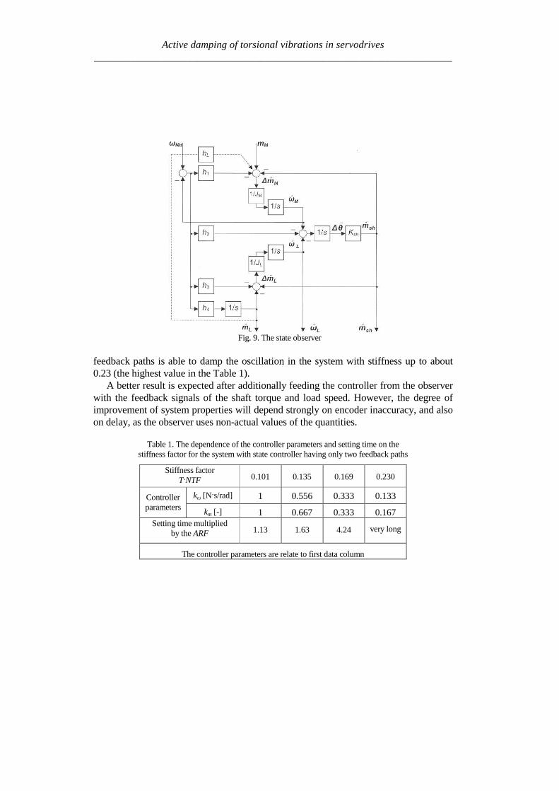
Active damping of torsional vibrations in servodrives_____________________________________________________________________
Simulation experiments has been carried out to find the range of stabile parameters atwhich presented SRRC could be used The results of this investigation can be summa-rised as followsStability boundary
- TmiddotNTF gt 012 for 08 lt R lt 2- TmiddotNTF gt 010 for 08 lt R lt 8- TmiddotNTF gt 003 for 035 lt R lt 8
Setting time Tω - ARF Tω lt18 for TmiddotNTF = 01 and 08 lt R lt 2- ARF Tω lt42 for TmiddotNTF = 008 and 2 lt R lt 8- ARF Tω lt51 for TmiddotNTF = 006 and 05 lt R lt 1
Presented slow resonance ratio controller is well fitting for system with relativelarge load inertia in relation to motor inertia In such case the virtual motor inertia isincreasing through using feedback coefficient K smaller than 1 and the whole systemis robust to real-time delays However if the load inertia is small feedback coeffi-cient K greater than 1 is needed and system is sensitive to any time lags It should benoted that when the motor inertia is much larger than the load inertia the resonanceratio control makes the disturbance response worse This fact suggests that the vibra-tion suppression and the disturbance rejection are opposite objectives [7]
6 LINEAR-QUADRATIC CONTROLLER WITH KALMAN FILTER
61 STATE AND DISTURBANCES OBSERVER
When using the LQ-controller state vector should be available State variables thatcannot be measured should be estimated
The Kalman Filter is one of proposed estimators [11] [12] [13] [17] Kalmanfilter theory allows estimating all state variables Theory presented in [11] determinesthe state variables They could be disturbed by Gaussian white noise which repre-sents all error sources and model inaccuracy [11] This is a narrow assumption thathas been avoided in his work This causes difficulties with theoretical tuning rules
Basing on filtering knowledge [11] the model of the system can be expressed bystate (23) and measurement (24) equations
1n e n e n nx x u w+ = + +A B (23)
n e n ny x v= +C (24)
Active damping of torsional vibrations in servodrives_____________________________________________________________________
where the control signal u is equal to the torque command mr and the output vector yis equal to mechanical position θ In equations (23) and (24) w represents a processnoise and v - measurement noise
It is assumed that the disturbing load torque (mL) is a part of measurement noiseand a part of state vector The assumption is only valid when the derivative of loadtorque is near to zero
0L
dm
dtasymp (25)
The state vector of observer has been extended by new estimated variable (Lm )
ˆˆ ˆˆ ˆ ˆT
M L sh Lx m mω ω θ = (26)
New state space matrices are equal
10 0 0 0
1 10 0 0
0 0 0
0 0 0 0 0
1 0 0 0 0
M
L Le
sh sh
J
J J
K K
minus minus =
minus
A
=
0
0
0
0
1
M
e
J
B
0
0
0
0
1
e
=
C (272829)
The equations of estimator are given by
( )| | 1 | 1
1| |
ˆ ˆ ˆ
ˆ ˆ ˆ
n n n n e n e n n
n n e n n e n
x x y x
x x u
minus minus
+
= + minus
= +
K C
A B (30)
where Ke is a Kalman filter gains which is computed by solving Ricatti equation[11] The gains can be calculated using recursive algorithm only one time and can bevalid for each step of control algorithm The noisersquos covariance of presented system(025ltRlt8 Ksh=1 equivalent of 14bit encoder) can be determine by matrix Qe
Active damping of torsional vibrations in servodrives_____________________________________________________________________
22
14
202 02 10 10
2e diag π =
Q (31)
which values represent covariances respectively with vector x elements The noisersquoscovariance of output signal may be described by
2
e 14
2
2R
π =
(32)
Theoretically the appropriate values should be real covariance but they was se-lected experimentally during system investigations It is noticed that last element ofQe matrix and Re is linked with the one known error It is caused by the quantisationduring obtaining real position from the 14-bit encoder
62 LQ CONTROL STRATEGY
The LQ-controller has several good properties [4] [9] and [18] It is applicable tomultivariable and time-varying systems when a model of the system can be availablein state space form (Fig 11) Changing the relations between the magnitude of ele-ments in weighting matrices we obtain compromise between the control speed and themagnitudes of control signals
Fig 11 Model of the system with LQ-controller and Kalman filter
The finding of answer presented in [9] is applicable to our system The generalformulation of the problem is to minimise the performance index J The following
Active damping of torsional vibrations in servodrives_____________________________________________________________________
deviations from steady state has been defined ∆x ∆u (for state and control variablesrespectively) The designed problem was reformulated to LQ-compensator with newdefined performance index J
( ) ( )( )2
0
T
r rJ R ux xinfin
= + ∆∆ ∆int Q (33)
where Qr and Rr are defined tuning matricesIn state controller the control-input signal is given by follows
r
xu
p
= minus
K (34)
Partitioning Kr and using integral control to cancel steady-state error
( )0
ˆt
M rdp dtω ω= minusint (35)
the control input signal yields
[ ] ( )1 2 3
0
ˆ
ˆ ˆ
ˆ
M t
L p M rd
sh
u K K K K dt
m
ωω ω ω = minus minus minus
int (36)
The main problem during solving LQ regulator is proper choosing the performanceindex J As shown in [9] Qr and Rr are given as
0 0
0 0
0 0 0 0
0 0 0
r
α αα α β
δ
minus minus + =
Q rR ε= (3738)
Performance index (33) can be expressed in more practical form
Active damping of torsional vibrations in servodrives_____________________________________________________________________
( ) ( )( ) ( )
2 2
2 20
M L L Ls
s s
J dtp p u u
α ω ω β ω ω
δ ε
infin minus + minus + = + minus + minus
int (39)
where Greek symbols mark weighting for α ndash torsional vibration suppression
β ndash command following δ ndash steady-state error ε ndash control input
The weight factors were selected experimentally α = 1 β = 100 δ = 100 ε = 01
63 SIMULATION RESULTS
Simulation experiments confirmed that there exists a range of delay at which theLQ-controller using signals dealt by Kalman filter can be constructed The wholesystem has been experimentally tuned (without any optimisation) to check how thetotal delay T influences system performance The preliminary results of investigationcan be briefly formulated as follows
ndash Delay TsdotNTF lt 008 has very small influence on system performance
ndash The setting time without delay is ARFsdotTω asymp 2 Similar performance can be ob-
tained for increasing delay only in limited range of inertia ratio
ndash TsdotNTF lt 008 and 025ltRlt05
ndash TsdotNTF lt 011 and R=1
ndash TsdotNTF lt 02 and 2 lt R lt 8
ndash When TsdotNTF lt 035 the system is stable but the setting time is unacceptable
large
7 CONCLUSION
It is possible to actively damp torsional vibration using single feedback signal fromencoder only Damping ability depends on the inertia ratio R and total delay T in thespeed control loop Because single feedback signal is considered and the controllerhas single output all analysed controllers can be treated as digital filters Apart fromvarious internal descriptions all controllers actually differ only in filter order and co-efficients Methods of calculation and tuning controller gains (or filter coefficients)are also different Unfortunately no systematic design methods have been found forthe analysed controllers Only heuristic approach for controller tuning was tested Themost complete and most promising results have been obtained for the unconventional
Active damping of torsional vibrations in servodrives_____________________________________________________________________
IPD controllers The near-optimum parameters have been found by simulation ex-periments for wide range of R and T These parameters can be directly applied in realPID controlled industrial drives
Another considered methods have been elaborated only partially Because theyconstitute filters of higher order than simple PI-controller probably better resultscould be obtained This possible advantage has not been fully confirmed in this workAuthors concentrate on practical rules for choosing suitable parameters of state con-troller and observer as well as gains of Kalman filter and LQ compensator
ACKONWLEDGEMENT
This work was partially supported by the grant 3 T10A 026 28
REFERENCES
[1] BOLOGNANI S VENTURATO A ZIGLIOTTO M Theoretical and experimental comparisonof speed controllers for elastic two-mass-systems Proc31st APESCrsquo2000 vol 3 pp1087-10922000
[2] DEUR J PERIC N Analysis of speed control system for electrical drives with elastic transmissionProc of the IEEE Int Symp ISIErsquo99 Bled Slovenia vol 2 pp 624-630 1999
[3] DEUR J PERIC N Pointing and tracking position control system for electrical drives with elastictransmission Proc 9th Int Conf PEMCrsquo2000 Kosice Slovak Republic pp7-1-7-6 2000
[4] FRANKLIN GF POWELL JD WORKMAN ML Digital Control of Dynamic Systems 3rdEdition Prentice Hall 1997
[5] GIERLOTKA K ZALEŚNY P Metoda obliczania parametroacutew układu regulacji napędu z połą-czeniem spręŜystym z dodatkowymi sprzęŜeniami zwrotnymi ZN Politechniki Śląskiej Elektrykaz170 (1999) str 65-72
[6] HORI Y SAWADA H CHUN Y Slow Resonance Ratio Control for Vibration Suppression andDisturbance Rejection in Torsional System IEEE Trans on Industrial Electronics vol 34 pp 162-168 1999
[7] HORI Y Comparison of Torsional Vibration Controls based on the Fast and Slow DisturbanceObservers Proc Int Conf IPEC95 Vol1 pp440-446 Yokohama 1995
[8] IWATA M ITOH S High Performance and Adaptive Motion Control System Based on IdentifiedMechanical Parameter Proc 3rd Int Workshop on Advanced Motion Control 1994 Berkeley
[9] JI J-K SUL S-K Kalman filter and LQ based speed controller for torsional vibration suppres-sion in a 2-mass motor drive system IEEE Trans Ind Electron vol 42 no 6 pp564ndash571 1995
[10] KALEJTA T MUSZYŃSKI R State observer for servodrive with flexibility Proc 4th Int SympELECTROMOTION`01 Bologna Italy vol 1 pp 159-164 2001
[11] KALMAN RE New Approach to Linear Filtering and Prediction Problems Trans of the ASMEJournal of Basic Engineering 1960 pp 374-382
[12] ORŁOWSKA-KOWALSKA T SZABAT K Zastosowanie regulatora stanu w układzie napędo-wym z połączeniem spręŜystym MaterVI Kraj Konf SENE 2003 tom III pp 679-685
[13] ORŁOWSKA-KOWALSKA T SZABAT K State Feedback Control of Two-Mass System withState Estimator Proc Int ConfEDPErsquo2003 Hihg Tatras Slovak Rep pp 590-595 2003
[14] ORŁOWSKA-KOWALSKA T SZABAT K Optimization of fuzzy-logic speed controller for DC
Active damping of torsional vibrations in servodrives_____________________________________________________________________
drive system with elastic joints IEEE Trans on Ind Applic vol 40 no 4 pp1138-1144 2004[15] MANABE S Coefficient Diagram Method Proc 14th IFAC Symp on Automatic Control in Aero-
space Seoul1998[16] MUSZYŃSKI R KACZMAREK T The elastic servo drive with state controller Archives of
Electrical Engineering vol LII no 2 pp 185-200 2003[17] SHIN D-J HUH U-Y Robust motion controller design for servo system with 2 mass characteris-
tics Proc 6th Inter Workshop on Advanced Motion Control 2000 pp 423-426[18] STEFANI R SAVANT C SHAHIAN B HOSTETTER G Design of Feedback Control Systems
Saunders College Publisher 1994[19] SZABAT K ORŁOWSKA-KOWALSKA T Tłumienie oscylacji prędkości w układzie napędowym
z połaczeniem spręŜystym Przegląd Elektrotechniczny vol LXXIX no 7-8 pp 474-482 2003[20] ШИЯНОВ А И МЕДВЕДЕВ ΒАМОРОЗОВ СВ Асинхронный злектропривод с упругой
нагрузкой и адаптивным регулятором ЗЛЕКТРИЧЕСТВО no 2 pp47divide49 2001[21] ZHANG G FURUSHO J Speed Control of Two-Inertia System by PIPID control IEEE Trans on
Industrial Electronics vol 47 no3 pp 603-609 2000
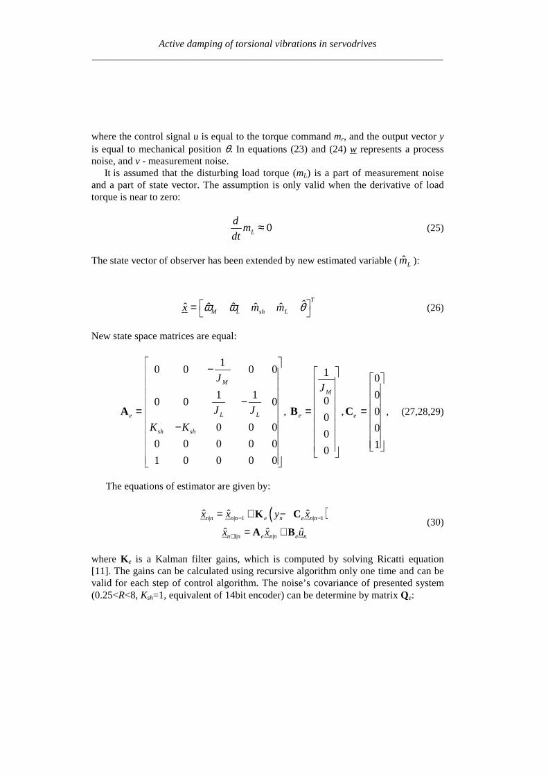
Active damping of torsional vibrations in servodrives_____________________________________________________________________
where the control signal u is equal to the torque command mr and the output vector yis equal to mechanical position θ In equations (23) and (24) w represents a processnoise and v - measurement noise
It is assumed that the disturbing load torque (mL) is a part of measurement noiseand a part of state vector The assumption is only valid when the derivative of loadtorque is near to zero
0L
dm
dtasymp (25)
The state vector of observer has been extended by new estimated variable (Lm )
ˆˆ ˆˆ ˆ ˆT
M L sh Lx m mω ω θ = (26)
New state space matrices are equal
10 0 0 0
1 10 0 0
0 0 0
0 0 0 0 0
1 0 0 0 0
M
L Le
sh sh
J
J J
K K
minus minus =
minus
A
=
0
0
0
0
1
M
e
J
B
0
0
0
0
1
e
=
C (272829)
The equations of estimator are given by
( )| | 1 | 1
1| |
ˆ ˆ ˆ
ˆ ˆ ˆ
n n n n e n e n n
n n e n n e n
x x y x
x x u
minus minus
+
= + minus
= +
K C
A B (30)
where Ke is a Kalman filter gains which is computed by solving Ricatti equation[11] The gains can be calculated using recursive algorithm only one time and can bevalid for each step of control algorithm The noisersquos covariance of presented system(025ltRlt8 Ksh=1 equivalent of 14bit encoder) can be determine by matrix Qe
Active damping of torsional vibrations in servodrives_____________________________________________________________________
22
14
202 02 10 10
2e diag π =
Q (31)
which values represent covariances respectively with vector x elements The noisersquoscovariance of output signal may be described by
2
e 14
2
2R
π =
(32)
Theoretically the appropriate values should be real covariance but they was se-lected experimentally during system investigations It is noticed that last element ofQe matrix and Re is linked with the one known error It is caused by the quantisationduring obtaining real position from the 14-bit encoder
62 LQ CONTROL STRATEGY
The LQ-controller has several good properties [4] [9] and [18] It is applicable tomultivariable and time-varying systems when a model of the system can be availablein state space form (Fig 11) Changing the relations between the magnitude of ele-ments in weighting matrices we obtain compromise between the control speed and themagnitudes of control signals
Fig 11 Model of the system with LQ-controller and Kalman filter
The finding of answer presented in [9] is applicable to our system The generalformulation of the problem is to minimise the performance index J The following
Active damping of torsional vibrations in servodrives_____________________________________________________________________
deviations from steady state has been defined ∆x ∆u (for state and control variablesrespectively) The designed problem was reformulated to LQ-compensator with newdefined performance index J
( ) ( )( )2
0
T
r rJ R ux xinfin
= + ∆∆ ∆int Q (33)
where Qr and Rr are defined tuning matricesIn state controller the control-input signal is given by follows
r
xu
p
= minus
K (34)
Partitioning Kr and using integral control to cancel steady-state error
( )0
ˆt
M rdp dtω ω= minusint (35)
the control input signal yields
[ ] ( )1 2 3
0
ˆ
ˆ ˆ
ˆ
M t
L p M rd
sh
u K K K K dt
m
ωω ω ω = minus minus minus
int (36)
The main problem during solving LQ regulator is proper choosing the performanceindex J As shown in [9] Qr and Rr are given as
0 0
0 0
0 0 0 0
0 0 0
r
α αα α β
δ
minus minus + =
Q rR ε= (3738)
Performance index (33) can be expressed in more practical form
Active damping of torsional vibrations in servodrives_____________________________________________________________________
( ) ( )( ) ( )
2 2
2 20
M L L Ls
s s
J dtp p u u
α ω ω β ω ω
δ ε
infin minus + minus + = + minus + minus
int (39)
where Greek symbols mark weighting for α ndash torsional vibration suppression
β ndash command following δ ndash steady-state error ε ndash control input
The weight factors were selected experimentally α = 1 β = 100 δ = 100 ε = 01
63 SIMULATION RESULTS
Simulation experiments confirmed that there exists a range of delay at which theLQ-controller using signals dealt by Kalman filter can be constructed The wholesystem has been experimentally tuned (without any optimisation) to check how thetotal delay T influences system performance The preliminary results of investigationcan be briefly formulated as follows
ndash Delay TsdotNTF lt 008 has very small influence on system performance
ndash The setting time without delay is ARFsdotTω asymp 2 Similar performance can be ob-
tained for increasing delay only in limited range of inertia ratio
ndash TsdotNTF lt 008 and 025ltRlt05
ndash TsdotNTF lt 011 and R=1
ndash TsdotNTF lt 02 and 2 lt R lt 8
ndash When TsdotNTF lt 035 the system is stable but the setting time is unacceptable
large
7 CONCLUSION
It is possible to actively damp torsional vibration using single feedback signal fromencoder only Damping ability depends on the inertia ratio R and total delay T in thespeed control loop Because single feedback signal is considered and the controllerhas single output all analysed controllers can be treated as digital filters Apart fromvarious internal descriptions all controllers actually differ only in filter order and co-efficients Methods of calculation and tuning controller gains (or filter coefficients)are also different Unfortunately no systematic design methods have been found forthe analysed controllers Only heuristic approach for controller tuning was tested Themost complete and most promising results have been obtained for the unconventional
Active damping of torsional vibrations in servodrives_____________________________________________________________________
IPD controllers The near-optimum parameters have been found by simulation ex-periments for wide range of R and T These parameters can be directly applied in realPID controlled industrial drives
Another considered methods have been elaborated only partially Because theyconstitute filters of higher order than simple PI-controller probably better resultscould be obtained This possible advantage has not been fully confirmed in this workAuthors concentrate on practical rules for choosing suitable parameters of state con-troller and observer as well as gains of Kalman filter and LQ compensator
ACKONWLEDGEMENT
This work was partially supported by the grant 3 T10A 026 28
REFERENCES
[1] BOLOGNANI S VENTURATO A ZIGLIOTTO M Theoretical and experimental comparisonof speed controllers for elastic two-mass-systems Proc31st APESCrsquo2000 vol 3 pp1087-10922000
[2] DEUR J PERIC N Analysis of speed control system for electrical drives with elastic transmissionProc of the IEEE Int Symp ISIErsquo99 Bled Slovenia vol 2 pp 624-630 1999
[3] DEUR J PERIC N Pointing and tracking position control system for electrical drives with elastictransmission Proc 9th Int Conf PEMCrsquo2000 Kosice Slovak Republic pp7-1-7-6 2000
[4] FRANKLIN GF POWELL JD WORKMAN ML Digital Control of Dynamic Systems 3rdEdition Prentice Hall 1997
[5] GIERLOTKA K ZALEŚNY P Metoda obliczania parametroacutew układu regulacji napędu z połą-czeniem spręŜystym z dodatkowymi sprzęŜeniami zwrotnymi ZN Politechniki Śląskiej Elektrykaz170 (1999) str 65-72
[6] HORI Y SAWADA H CHUN Y Slow Resonance Ratio Control for Vibration Suppression andDisturbance Rejection in Torsional System IEEE Trans on Industrial Electronics vol 34 pp 162-168 1999
[7] HORI Y Comparison of Torsional Vibration Controls based on the Fast and Slow DisturbanceObservers Proc Int Conf IPEC95 Vol1 pp440-446 Yokohama 1995
[8] IWATA M ITOH S High Performance and Adaptive Motion Control System Based on IdentifiedMechanical Parameter Proc 3rd Int Workshop on Advanced Motion Control 1994 Berkeley
[9] JI J-K SUL S-K Kalman filter and LQ based speed controller for torsional vibration suppres-sion in a 2-mass motor drive system IEEE Trans Ind Electron vol 42 no 6 pp564ndash571 1995
[10] KALEJTA T MUSZYŃSKI R State observer for servodrive with flexibility Proc 4th Int SympELECTROMOTION`01 Bologna Italy vol 1 pp 159-164 2001
[11] KALMAN RE New Approach to Linear Filtering and Prediction Problems Trans of the ASMEJournal of Basic Engineering 1960 pp 374-382
[12] ORŁOWSKA-KOWALSKA T SZABAT K Zastosowanie regulatora stanu w układzie napędo-wym z połączeniem spręŜystym MaterVI Kraj Konf SENE 2003 tom III pp 679-685
[13] ORŁOWSKA-KOWALSKA T SZABAT K State Feedback Control of Two-Mass System withState Estimator Proc Int ConfEDPErsquo2003 Hihg Tatras Slovak Rep pp 590-595 2003
[14] ORŁOWSKA-KOWALSKA T SZABAT K Optimization of fuzzy-logic speed controller for DC
Active damping of torsional vibrations in servodrives_____________________________________________________________________
drive system with elastic joints IEEE Trans on Ind Applic vol 40 no 4 pp1138-1144 2004[15] MANABE S Coefficient Diagram Method Proc 14th IFAC Symp on Automatic Control in Aero-
space Seoul1998[16] MUSZYŃSKI R KACZMAREK T The elastic servo drive with state controller Archives of
Electrical Engineering vol LII no 2 pp 185-200 2003[17] SHIN D-J HUH U-Y Robust motion controller design for servo system with 2 mass characteris-
tics Proc 6th Inter Workshop on Advanced Motion Control 2000 pp 423-426[18] STEFANI R SAVANT C SHAHIAN B HOSTETTER G Design of Feedback Control Systems
Saunders College Publisher 1994[19] SZABAT K ORŁOWSKA-KOWALSKA T Tłumienie oscylacji prędkości w układzie napędowym
z połaczeniem spręŜystym Przegląd Elektrotechniczny vol LXXIX no 7-8 pp 474-482 2003[20] ШИЯНОВ А И МЕДВЕДЕВ ΒАМОРОЗОВ СВ Асинхронный злектропривод с упругой
нагрузкой и адаптивным регулятором ЗЛЕКТРИЧЕСТВО no 2 pp47divide49 2001[21] ZHANG G FURUSHO J Speed Control of Two-Inertia System by PIPID control IEEE Trans on
Industrial Electronics vol 47 no3 pp 603-609 2000
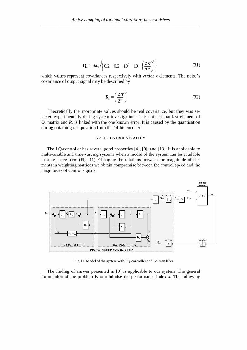
Active damping of torsional vibrations in servodrives_____________________________________________________________________
22
14
202 02 10 10
2e diag π =
Q (31)
which values represent covariances respectively with vector x elements The noisersquoscovariance of output signal may be described by
2
e 14
2
2R
π =
(32)
Theoretically the appropriate values should be real covariance but they was se-lected experimentally during system investigations It is noticed that last element ofQe matrix and Re is linked with the one known error It is caused by the quantisationduring obtaining real position from the 14-bit encoder
62 LQ CONTROL STRATEGY
The LQ-controller has several good properties [4] [9] and [18] It is applicable tomultivariable and time-varying systems when a model of the system can be availablein state space form (Fig 11) Changing the relations between the magnitude of ele-ments in weighting matrices we obtain compromise between the control speed and themagnitudes of control signals
Fig 11 Model of the system with LQ-controller and Kalman filter
The finding of answer presented in [9] is applicable to our system The generalformulation of the problem is to minimise the performance index J The following
Active damping of torsional vibrations in servodrives_____________________________________________________________________
deviations from steady state has been defined ∆x ∆u (for state and control variablesrespectively) The designed problem was reformulated to LQ-compensator with newdefined performance index J
( ) ( )( )2
0
T
r rJ R ux xinfin
= + ∆∆ ∆int Q (33)
where Qr and Rr are defined tuning matricesIn state controller the control-input signal is given by follows
r
xu
p
= minus
K (34)
Partitioning Kr and using integral control to cancel steady-state error
( )0
ˆt
M rdp dtω ω= minusint (35)
the control input signal yields
[ ] ( )1 2 3
0
ˆ
ˆ ˆ
ˆ
M t
L p M rd
sh
u K K K K dt
m
ωω ω ω = minus minus minus
int (36)
The main problem during solving LQ regulator is proper choosing the performanceindex J As shown in [9] Qr and Rr are given as
0 0
0 0
0 0 0 0
0 0 0
r
α αα α β
δ
minus minus + =
Q rR ε= (3738)
Performance index (33) can be expressed in more practical form
Active damping of torsional vibrations in servodrives_____________________________________________________________________
( ) ( )( ) ( )
2 2
2 20
M L L Ls
s s
J dtp p u u
α ω ω β ω ω
δ ε
infin minus + minus + = + minus + minus
int (39)
where Greek symbols mark weighting for α ndash torsional vibration suppression
β ndash command following δ ndash steady-state error ε ndash control input
The weight factors were selected experimentally α = 1 β = 100 δ = 100 ε = 01
63 SIMULATION RESULTS
Simulation experiments confirmed that there exists a range of delay at which theLQ-controller using signals dealt by Kalman filter can be constructed The wholesystem has been experimentally tuned (without any optimisation) to check how thetotal delay T influences system performance The preliminary results of investigationcan be briefly formulated as follows
ndash Delay TsdotNTF lt 008 has very small influence on system performance
ndash The setting time without delay is ARFsdotTω asymp 2 Similar performance can be ob-
tained for increasing delay only in limited range of inertia ratio
ndash TsdotNTF lt 008 and 025ltRlt05
ndash TsdotNTF lt 011 and R=1
ndash TsdotNTF lt 02 and 2 lt R lt 8
ndash When TsdotNTF lt 035 the system is stable but the setting time is unacceptable
large
7 CONCLUSION
It is possible to actively damp torsional vibration using single feedback signal fromencoder only Damping ability depends on the inertia ratio R and total delay T in thespeed control loop Because single feedback signal is considered and the controllerhas single output all analysed controllers can be treated as digital filters Apart fromvarious internal descriptions all controllers actually differ only in filter order and co-efficients Methods of calculation and tuning controller gains (or filter coefficients)are also different Unfortunately no systematic design methods have been found forthe analysed controllers Only heuristic approach for controller tuning was tested Themost complete and most promising results have been obtained for the unconventional
Active damping of torsional vibrations in servodrives_____________________________________________________________________
IPD controllers The near-optimum parameters have been found by simulation ex-periments for wide range of R and T These parameters can be directly applied in realPID controlled industrial drives
Another considered methods have been elaborated only partially Because theyconstitute filters of higher order than simple PI-controller probably better resultscould be obtained This possible advantage has not been fully confirmed in this workAuthors concentrate on practical rules for choosing suitable parameters of state con-troller and observer as well as gains of Kalman filter and LQ compensator
ACKONWLEDGEMENT
This work was partially supported by the grant 3 T10A 026 28
REFERENCES
[1] BOLOGNANI S VENTURATO A ZIGLIOTTO M Theoretical and experimental comparisonof speed controllers for elastic two-mass-systems Proc31st APESCrsquo2000 vol 3 pp1087-10922000
[2] DEUR J PERIC N Analysis of speed control system for electrical drives with elastic transmissionProc of the IEEE Int Symp ISIErsquo99 Bled Slovenia vol 2 pp 624-630 1999
[3] DEUR J PERIC N Pointing and tracking position control system for electrical drives with elastictransmission Proc 9th Int Conf PEMCrsquo2000 Kosice Slovak Republic pp7-1-7-6 2000
[4] FRANKLIN GF POWELL JD WORKMAN ML Digital Control of Dynamic Systems 3rdEdition Prentice Hall 1997
[5] GIERLOTKA K ZALEŚNY P Metoda obliczania parametroacutew układu regulacji napędu z połą-czeniem spręŜystym z dodatkowymi sprzęŜeniami zwrotnymi ZN Politechniki Śląskiej Elektrykaz170 (1999) str 65-72
[6] HORI Y SAWADA H CHUN Y Slow Resonance Ratio Control for Vibration Suppression andDisturbance Rejection in Torsional System IEEE Trans on Industrial Electronics vol 34 pp 162-168 1999
[7] HORI Y Comparison of Torsional Vibration Controls based on the Fast and Slow DisturbanceObservers Proc Int Conf IPEC95 Vol1 pp440-446 Yokohama 1995
[8] IWATA M ITOH S High Performance and Adaptive Motion Control System Based on IdentifiedMechanical Parameter Proc 3rd Int Workshop on Advanced Motion Control 1994 Berkeley
[9] JI J-K SUL S-K Kalman filter and LQ based speed controller for torsional vibration suppres-sion in a 2-mass motor drive system IEEE Trans Ind Electron vol 42 no 6 pp564ndash571 1995
[10] KALEJTA T MUSZYŃSKI R State observer for servodrive with flexibility Proc 4th Int SympELECTROMOTION`01 Bologna Italy vol 1 pp 159-164 2001
[11] KALMAN RE New Approach to Linear Filtering and Prediction Problems Trans of the ASMEJournal of Basic Engineering 1960 pp 374-382
[12] ORŁOWSKA-KOWALSKA T SZABAT K Zastosowanie regulatora stanu w układzie napędo-wym z połączeniem spręŜystym MaterVI Kraj Konf SENE 2003 tom III pp 679-685
[13] ORŁOWSKA-KOWALSKA T SZABAT K State Feedback Control of Two-Mass System withState Estimator Proc Int ConfEDPErsquo2003 Hihg Tatras Slovak Rep pp 590-595 2003
[14] ORŁOWSKA-KOWALSKA T SZABAT K Optimization of fuzzy-logic speed controller for DC
Active damping of torsional vibrations in servodrives_____________________________________________________________________
drive system with elastic joints IEEE Trans on Ind Applic vol 40 no 4 pp1138-1144 2004[15] MANABE S Coefficient Diagram Method Proc 14th IFAC Symp on Automatic Control in Aero-
space Seoul1998[16] MUSZYŃSKI R KACZMAREK T The elastic servo drive with state controller Archives of
Electrical Engineering vol LII no 2 pp 185-200 2003[17] SHIN D-J HUH U-Y Robust motion controller design for servo system with 2 mass characteris-
tics Proc 6th Inter Workshop on Advanced Motion Control 2000 pp 423-426[18] STEFANI R SAVANT C SHAHIAN B HOSTETTER G Design of Feedback Control Systems
Saunders College Publisher 1994[19] SZABAT K ORŁOWSKA-KOWALSKA T Tłumienie oscylacji prędkości w układzie napędowym
z połaczeniem spręŜystym Przegląd Elektrotechniczny vol LXXIX no 7-8 pp 474-482 2003[20] ШИЯНОВ А И МЕДВЕДЕВ ΒАМОРОЗОВ СВ Асинхронный злектропривод с упругой
нагрузкой и адаптивным регулятором ЗЛЕКТРИЧЕСТВО no 2 pp47divide49 2001[21] ZHANG G FURUSHO J Speed Control of Two-Inertia System by PIPID control IEEE Trans on
Industrial Electronics vol 47 no3 pp 603-609 2000
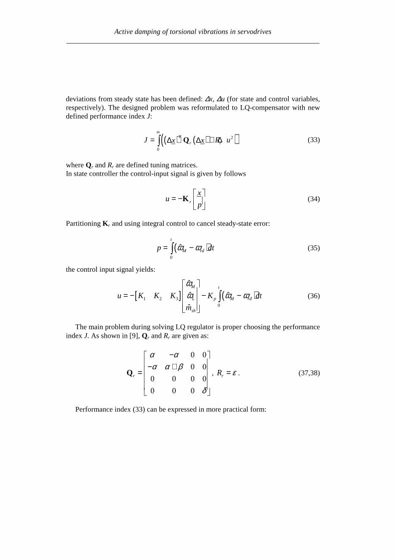
Active damping of torsional vibrations in servodrives_____________________________________________________________________
deviations from steady state has been defined ∆x ∆u (for state and control variablesrespectively) The designed problem was reformulated to LQ-compensator with newdefined performance index J
( ) ( )( )2
0
T
r rJ R ux xinfin
= + ∆∆ ∆int Q (33)
where Qr and Rr are defined tuning matricesIn state controller the control-input signal is given by follows
r
xu
p
= minus
K (34)
Partitioning Kr and using integral control to cancel steady-state error
( )0
ˆt
M rdp dtω ω= minusint (35)
the control input signal yields
[ ] ( )1 2 3
0
ˆ
ˆ ˆ
ˆ
M t
L p M rd
sh
u K K K K dt
m
ωω ω ω = minus minus minus
int (36)
The main problem during solving LQ regulator is proper choosing the performanceindex J As shown in [9] Qr and Rr are given as
0 0
0 0
0 0 0 0
0 0 0
r
α αα α β
δ
minus minus + =
Q rR ε= (3738)
Performance index (33) can be expressed in more practical form
Active damping of torsional vibrations in servodrives_____________________________________________________________________
( ) ( )( ) ( )
2 2
2 20
M L L Ls
s s
J dtp p u u
α ω ω β ω ω
δ ε
infin minus + minus + = + minus + minus
int (39)
where Greek symbols mark weighting for α ndash torsional vibration suppression
β ndash command following δ ndash steady-state error ε ndash control input
The weight factors were selected experimentally α = 1 β = 100 δ = 100 ε = 01
63 SIMULATION RESULTS
Simulation experiments confirmed that there exists a range of delay at which theLQ-controller using signals dealt by Kalman filter can be constructed The wholesystem has been experimentally tuned (without any optimisation) to check how thetotal delay T influences system performance The preliminary results of investigationcan be briefly formulated as follows
ndash Delay TsdotNTF lt 008 has very small influence on system performance
ndash The setting time without delay is ARFsdotTω asymp 2 Similar performance can be ob-
tained for increasing delay only in limited range of inertia ratio
ndash TsdotNTF lt 008 and 025ltRlt05
ndash TsdotNTF lt 011 and R=1
ndash TsdotNTF lt 02 and 2 lt R lt 8
ndash When TsdotNTF lt 035 the system is stable but the setting time is unacceptable
large
7 CONCLUSION
It is possible to actively damp torsional vibration using single feedback signal fromencoder only Damping ability depends on the inertia ratio R and total delay T in thespeed control loop Because single feedback signal is considered and the controllerhas single output all analysed controllers can be treated as digital filters Apart fromvarious internal descriptions all controllers actually differ only in filter order and co-efficients Methods of calculation and tuning controller gains (or filter coefficients)are also different Unfortunately no systematic design methods have been found forthe analysed controllers Only heuristic approach for controller tuning was tested Themost complete and most promising results have been obtained for the unconventional
Active damping of torsional vibrations in servodrives_____________________________________________________________________
IPD controllers The near-optimum parameters have been found by simulation ex-periments for wide range of R and T These parameters can be directly applied in realPID controlled industrial drives
Another considered methods have been elaborated only partially Because theyconstitute filters of higher order than simple PI-controller probably better resultscould be obtained This possible advantage has not been fully confirmed in this workAuthors concentrate on practical rules for choosing suitable parameters of state con-troller and observer as well as gains of Kalman filter and LQ compensator
ACKONWLEDGEMENT
This work was partially supported by the grant 3 T10A 026 28
REFERENCES
[1] BOLOGNANI S VENTURATO A ZIGLIOTTO M Theoretical and experimental comparisonof speed controllers for elastic two-mass-systems Proc31st APESCrsquo2000 vol 3 pp1087-10922000
[2] DEUR J PERIC N Analysis of speed control system for electrical drives with elastic transmissionProc of the IEEE Int Symp ISIErsquo99 Bled Slovenia vol 2 pp 624-630 1999
[3] DEUR J PERIC N Pointing and tracking position control system for electrical drives with elastictransmission Proc 9th Int Conf PEMCrsquo2000 Kosice Slovak Republic pp7-1-7-6 2000
[4] FRANKLIN GF POWELL JD WORKMAN ML Digital Control of Dynamic Systems 3rdEdition Prentice Hall 1997
[5] GIERLOTKA K ZALEŚNY P Metoda obliczania parametroacutew układu regulacji napędu z połą-czeniem spręŜystym z dodatkowymi sprzęŜeniami zwrotnymi ZN Politechniki Śląskiej Elektrykaz170 (1999) str 65-72
[6] HORI Y SAWADA H CHUN Y Slow Resonance Ratio Control for Vibration Suppression andDisturbance Rejection in Torsional System IEEE Trans on Industrial Electronics vol 34 pp 162-168 1999
[7] HORI Y Comparison of Torsional Vibration Controls based on the Fast and Slow DisturbanceObservers Proc Int Conf IPEC95 Vol1 pp440-446 Yokohama 1995
[8] IWATA M ITOH S High Performance and Adaptive Motion Control System Based on IdentifiedMechanical Parameter Proc 3rd Int Workshop on Advanced Motion Control 1994 Berkeley
[9] JI J-K SUL S-K Kalman filter and LQ based speed controller for torsional vibration suppres-sion in a 2-mass motor drive system IEEE Trans Ind Electron vol 42 no 6 pp564ndash571 1995
[10] KALEJTA T MUSZYŃSKI R State observer for servodrive with flexibility Proc 4th Int SympELECTROMOTION`01 Bologna Italy vol 1 pp 159-164 2001
[11] KALMAN RE New Approach to Linear Filtering and Prediction Problems Trans of the ASMEJournal of Basic Engineering 1960 pp 374-382
[12] ORŁOWSKA-KOWALSKA T SZABAT K Zastosowanie regulatora stanu w układzie napędo-wym z połączeniem spręŜystym MaterVI Kraj Konf SENE 2003 tom III pp 679-685
[13] ORŁOWSKA-KOWALSKA T SZABAT K State Feedback Control of Two-Mass System withState Estimator Proc Int ConfEDPErsquo2003 Hihg Tatras Slovak Rep pp 590-595 2003
[14] ORŁOWSKA-KOWALSKA T SZABAT K Optimization of fuzzy-logic speed controller for DC
Active damping of torsional vibrations in servodrives_____________________________________________________________________
drive system with elastic joints IEEE Trans on Ind Applic vol 40 no 4 pp1138-1144 2004[15] MANABE S Coefficient Diagram Method Proc 14th IFAC Symp on Automatic Control in Aero-
space Seoul1998[16] MUSZYŃSKI R KACZMAREK T The elastic servo drive with state controller Archives of
Electrical Engineering vol LII no 2 pp 185-200 2003[17] SHIN D-J HUH U-Y Robust motion controller design for servo system with 2 mass characteris-
tics Proc 6th Inter Workshop on Advanced Motion Control 2000 pp 423-426[18] STEFANI R SAVANT C SHAHIAN B HOSTETTER G Design of Feedback Control Systems
Saunders College Publisher 1994[19] SZABAT K ORŁOWSKA-KOWALSKA T Tłumienie oscylacji prędkości w układzie napędowym
z połaczeniem spręŜystym Przegląd Elektrotechniczny vol LXXIX no 7-8 pp 474-482 2003[20] ШИЯНОВ А И МЕДВЕДЕВ ΒАМОРОЗОВ СВ Асинхронный злектропривод с упругой
нагрузкой и адаптивным регулятором ЗЛЕКТРИЧЕСТВО no 2 pp47divide49 2001[21] ZHANG G FURUSHO J Speed Control of Two-Inertia System by PIPID control IEEE Trans on
Industrial Electronics vol 47 no3 pp 603-609 2000
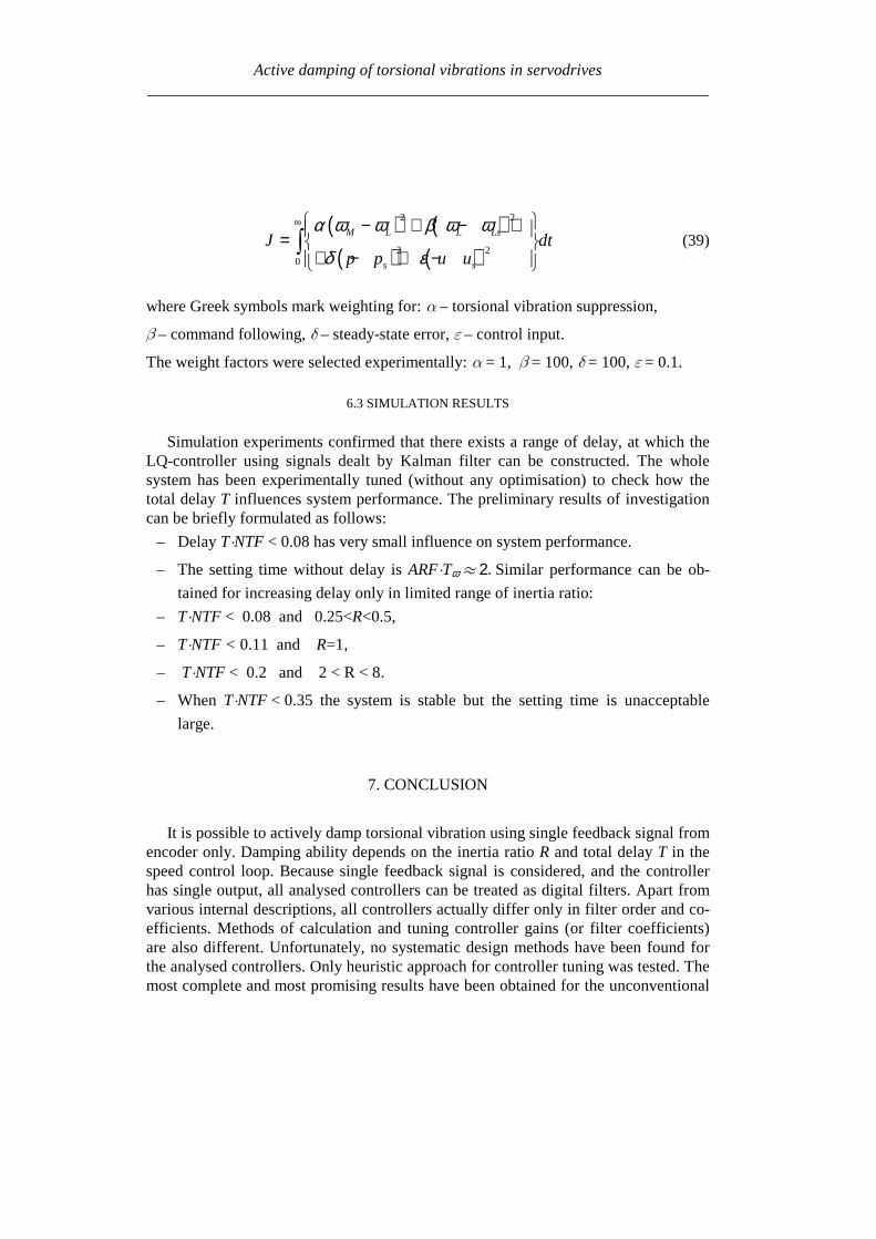
Active damping of torsional vibrations in servodrives_____________________________________________________________________
IPD controllers The near-optimum parameters have been found by simulation ex-periments for wide range of R and T These parameters can be directly applied in realPID controlled industrial drives
Another considered methods have been elaborated only partially Because theyconstitute filters of higher order than simple PI-controller probably better resultscould be obtained This possible advantage has not been fully confirmed in this workAuthors concentrate on practical rules for choosing suitable parameters of state con-troller and observer as well as gains of Kalman filter and LQ compensator
ACKONWLEDGEMENT
This work was partially supported by the grant 3 T10A 026 28
REFERENCES
[1] BOLOGNANI S VENTURATO A ZIGLIOTTO M Theoretical and experimental comparisonof speed controllers for elastic two-mass-systems Proc31st APESCrsquo2000 vol 3 pp1087-10922000
[2] DEUR J PERIC N Analysis of speed control system for electrical drives with elastic transmissionProc of the IEEE Int Symp ISIErsquo99 Bled Slovenia vol 2 pp 624-630 1999
[3] DEUR J PERIC N Pointing and tracking position control system for electrical drives with elastictransmission Proc 9th Int Conf PEMCrsquo2000 Kosice Slovak Republic pp7-1-7-6 2000
[4] FRANKLIN GF POWELL JD WORKMAN ML Digital Control of Dynamic Systems 3rdEdition Prentice Hall 1997
[5] GIERLOTKA K ZALEŚNY P Metoda obliczania parametroacutew układu regulacji napędu z połą-czeniem spręŜystym z dodatkowymi sprzęŜeniami zwrotnymi ZN Politechniki Śląskiej Elektrykaz170 (1999) str 65-72
[6] HORI Y SAWADA H CHUN Y Slow Resonance Ratio Control for Vibration Suppression andDisturbance Rejection in Torsional System IEEE Trans on Industrial Electronics vol 34 pp 162-168 1999
[7] HORI Y Comparison of Torsional Vibration Controls based on the Fast and Slow DisturbanceObservers Proc Int Conf IPEC95 Vol1 pp440-446 Yokohama 1995
[8] IWATA M ITOH S High Performance and Adaptive Motion Control System Based on IdentifiedMechanical Parameter Proc 3rd Int Workshop on Advanced Motion Control 1994 Berkeley
[9] JI J-K SUL S-K Kalman filter and LQ based speed controller for torsional vibration suppres-sion in a 2-mass motor drive system IEEE Trans Ind Electron vol 42 no 6 pp564ndash571 1995
[10] KALEJTA T MUSZYŃSKI R State observer for servodrive with flexibility Proc 4th Int SympELECTROMOTION`01 Bologna Italy vol 1 pp 159-164 2001
[11] KALMAN RE New Approach to Linear Filtering and Prediction Problems Trans of the ASMEJournal of Basic Engineering 1960 pp 374-382
[12] ORŁOWSKA-KOWALSKA T SZABAT K Zastosowanie regulatora stanu w układzie napędo-wym z połączeniem spręŜystym MaterVI Kraj Konf SENE 2003 tom III pp 679-685
[13] ORŁOWSKA-KOWALSKA T SZABAT K State Feedback Control of Two-Mass System withState Estimator Proc Int ConfEDPErsquo2003 Hihg Tatras Slovak Rep pp 590-595 2003
[14] ORŁOWSKA-KOWALSKA T SZABAT K Optimization of fuzzy-logic speed controller for DC
Active damping of torsional vibrations in servodrives_____________________________________________________________________
drive system with elastic joints IEEE Trans on Ind Applic vol 40 no 4 pp1138-1144 2004[15] MANABE S Coefficient Diagram Method Proc 14th IFAC Symp on Automatic Control in Aero-
space Seoul1998[16] MUSZYŃSKI R KACZMAREK T The elastic servo drive with state controller Archives of
Electrical Engineering vol LII no 2 pp 185-200 2003[17] SHIN D-J HUH U-Y Robust motion controller design for servo system with 2 mass characteris-
tics Proc 6th Inter Workshop on Advanced Motion Control 2000 pp 423-426[18] STEFANI R SAVANT C SHAHIAN B HOSTETTER G Design of Feedback Control Systems
Saunders College Publisher 1994[19] SZABAT K ORŁOWSKA-KOWALSKA T Tłumienie oscylacji prędkości w układzie napędowym
z połaczeniem spręŜystym Przegląd Elektrotechniczny vol LXXIX no 7-8 pp 474-482 2003[20] ШИЯНОВ А И МЕДВЕДЕВ ΒАМОРОЗОВ СВ Асинхронный злектропривод с упругой
нагрузкой и адаптивным регулятором ЗЛЕКТРИЧЕСТВО no 2 pp47divide49 2001[21] ZHANG G FURUSHO J Speed Control of Two-Inertia System by PIPID control IEEE Trans on
Industrial Electronics vol 47 no3 pp 603-609 2000