aer 201: engineering design - skule
TRANSCRIPT

AER 201: Engineering DesignCourse Manual
Victor RagusilaTodd Reichert
Cameron RobertsonM. Reza Emami
January 2015
1

Contents
1 Course Organization 31.1 Outline . . . . . . . . . . . . . . . . . . . . . . . . . . . . . . . . . . . . . . . 31.2 Schedule . . . . . . . . . . . . . . . . . . . . . . . . . . . . . . . . . . . . . . 41.3 Course Procedure . . . . . . . . . . . . . . . . . . . . . . . . . . . . . . . . . 5
2 Game Description 92.1 Objective . . . . . . . . . . . . . . . . . . . . . . . . . . . . . . . . . . . . . 92.2 Game Specifications . . . . . . . . . . . . . . . . . . . . . . . . . . . . . . . 92.3 Gameplay Operation . . . . . . . . . . . . . . . . . . . . . . . . . . . . . . . 122.4 Constraints . . . . . . . . . . . . . . . . . . . . . . . . . . . . . . . . . . . . 132.5 Scoring . . . . . . . . . . . . . . . . . . . . . . . . . . . . . . . . . . . . . . . 142.6 Design Criteria of Solution . . . . . . . . . . . . . . . . . . . . . . . . . . . . 142.7 Statement of Work . . . . . . . . . . . . . . . . . . . . . . . . . . . . . . . . 15
3 Marking Scheme 163.1 Grading Outline . . . . . . . . . . . . . . . . . . . . . . . . . . . . . . . . . . 163.2 Budget Cap . . . . . . . . . . . . . . . . . . . . . . . . . . . . . . . . . . . . 163.3 Project Proposal . . . . . . . . . . . . . . . . . . . . . . . . . . . . . . . . . 173.4 Progress Evaluations . . . . . . . . . . . . . . . . . . . . . . . . . . . . . . . 193.5 Notebook Evaluations . . . . . . . . . . . . . . . . . . . . . . . . . . . . . . 243.6 Design Competition . . . . . . . . . . . . . . . . . . . . . . . . . . . . . . . . 253.7 Final Report . . . . . . . . . . . . . . . . . . . . . . . . . . . . . . . . . . . . 273.8 Allocation of Team Marks . . . . . . . . . . . . . . . . . . . . . . . . . . . . 29
2

1 Course Organization
1.1 Outline
Instructors
Cameron Robertson, MASc, PEng [email protected] Reichert, PhD [email protected] Ragusila, PhD Candidate [email protected]
Teaching Assistants
Bazzocchi Michael [email protected] Laszlo-Peter [email protected] Boone [email protected] Christopher [email protected] Yasir [email protected] Carl [email protected] Ian [email protected] Tomas [email protected] Nikhil [email protected] Elias Fernando [email protected] Anurag [email protected] Tianhang [email protected] Kaizad [email protected] Jacek [email protected]
Lectures
1 Monday Week 1 11:00-12:00 SF11052 Tuesday Week 1 14:00-15:00 MC1023 Wednesday Week 1 14:00-15:00 MC1024 Friday Week 1 14:00-15:00 HS6105 Monday Week 2 11:00-12:00 SF11056 Friday Week 2 14:00-15:00 HS6107 Monday Week 3 11:00-12:00 SF1105
Laboratory
Monday 13:00-18:00 SF4003, SF4102, SF4103Tuesday 13:00-18:00 SF4003, SF4102, SF4103Wednesday 13:00-18:00 SF4003, SF4102, SF4103Friday 14:00-18:00 SF4003, SF4102, SF4103
Please note: during the first week of class labs sessions start at 15:00.
3
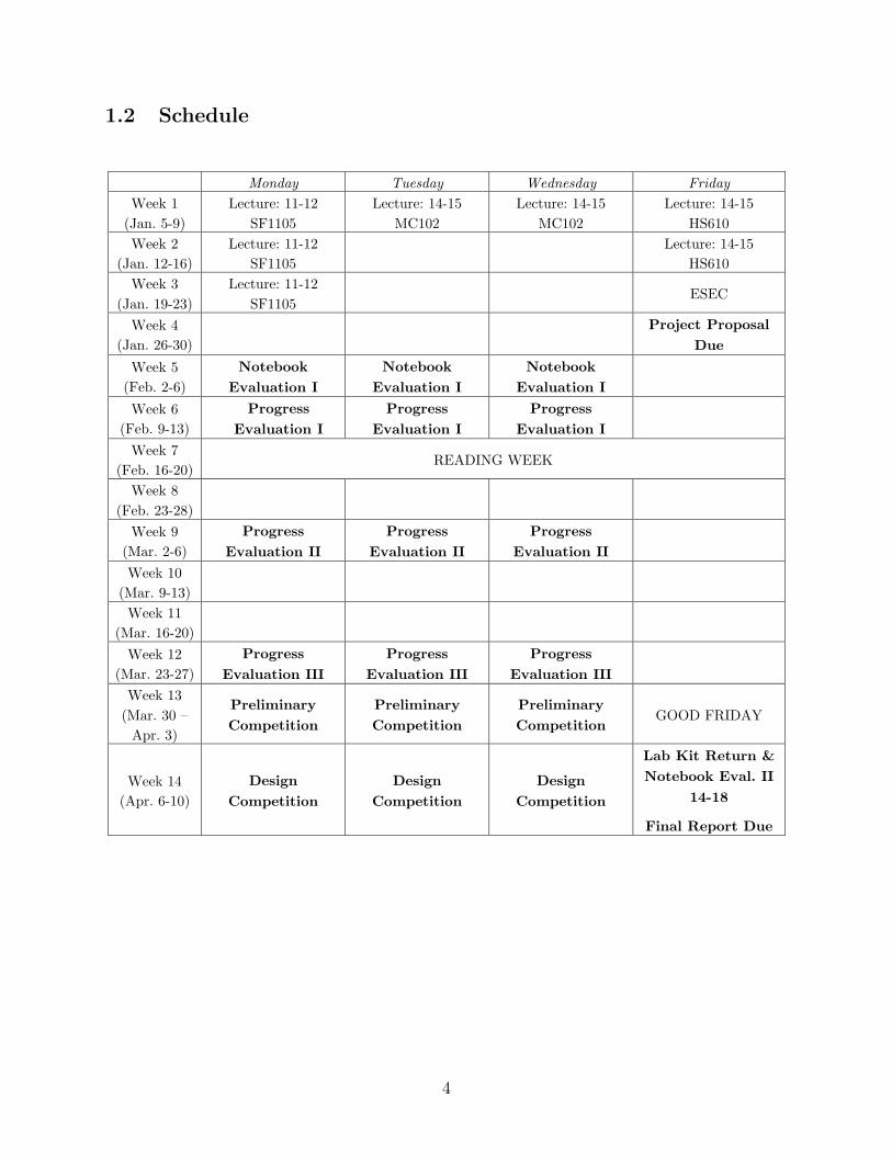
1.2 Schedule
Monday Tuesday Wednesday Friday Week 1
(Jan. 5-9) Lecture: 11-12
SF1105 Lecture: 14-15
MC102 Lecture: 14-15
MC102 Lecture: 14-15
HS610 Week 2
(Jan. 12-16) Lecture: 11-12
SF1105
Lecture: 14-15 HS610
Week 3 (Jan. 19-23)
Lecture: 11-12 SF1105
ESEC
Week 4 (Jan. 26-30)
Project Proposal
Due Week 5
(Feb. 2-6) Notebook
Evaluation I Notebook
Evaluation I Notebook
Evaluation I
Week 6 (Feb. 9-13)
Progress Evaluation I
Progress Evaluation I
Progress Evaluation I
Week 7 (Feb. 16-20)
READING WEEK
Week 8 (Feb. 23-28)
Week 9 (Mar. 2-6)
Progress Evaluation II
Progress Evaluation II
Progress Evaluation II
Week 10 (Mar. 9-13)
Week 11 (Mar. 16-20)
Week 12 (Mar. 23-27)
Progress Evaluation III
Progress Evaluation III
Progress Evaluation III
Week 13 (Mar. 30 –
Apr. 3)
Preliminary Competition
Preliminary Competition
Preliminary Competition
GOOD FRIDAY
Week 14 (Apr. 6-10)
Design Competition
Design Competition
Design Competition
Lab Kit Return & Notebook Eval. II
14-18
Final Report Due
4

1.3 Course Procedure
Welcome to AER201 Engineering Design! The engineering design course is a complex pro-cess, due to its hands-on nature and the complexity of engineering design. This course isabout much more than simply building a robot, although that in itself is an incredibly ex-citing and rewarding experience. This case study in engineering design is an opportunity toput theory into practice, to gain experience with various design tools and strategies and tolearn the difference between what makes a good design on paper, and what makes a gooddesign when you add the uncertainties of the “real world”.
In this course there is no single “good design” and no single “best” way to achieve it,and different design teams will use different tools and procedures in their design work, andpropose very different solutions to the same problem. Through the lectures we will try togive insight on design strategies and the technical aspects of the various subsystems, butoverall this is an experience where you learn by doing.
Take the time to get familiar with the course procedure and the evaluations. As withmany elements of the course it will be up to you to ensure that you remain on track, stayorganized, and make the most of your learning experience.
1.3.1 Course Notes
All lecture notes will be available on the blackboard portal.The recommended text for the course is “Multidisciplinary Engineering Design: from
theory to practice” by M.R. Emami, which can be found in the U of T Bookstore.A manual for the Arduino microcontroller is included in the Project Kit, but additional
references for the Arduino system are highly recommended. “Arduino Cookbook” by M.Margolis and “Beginning Arduino” by M. McRoberts are books with excellent reviews.
1.3.2 Blackboard
The Blackboard portal will be used to post all course documents and host discussion forums,which are recommended as an excellent resources for students to share information and helpeach other throughout the course. All online submissions are to be done on blackboard.Students are required to check the portal often, as any announcements will be posted on theportal.
1.3.3 First Lab Session and Kit Distribution
The teams will show up in the first lab day (Monday, Tuesday or Wednesday from 15:00 to18:00), which will be both very important and very hectic:
1. First the teams will find their assigned TA.
2. The students will give the TA $100 deposit for the Design Kit. For details on the DesignKit, section 2.1 in “Multidisciplinary Engineering Design: from theory to practice”.
3. The students will give the TA $250 for the Project Kit. For more details on the ProjectKit, see below.
5

4. The TA will give the students the Design and Project Kits.
5. The students will check the Design Kit to make sure everything is present. The kitswill be checked again by the TA at the end of the course, and anything missing orbroken will be deducted from the $100 deposit.
6. The Electromechanical member of each team will have to attend the safety trainingtutorial. This training session is 3h long, from 15:00 to 18:00. The attendance ismandatory for all Electromechanical members. Each student must attend the trainingin their lab session (and only that session).
1.3.4 Design Kit
The Design Kit contains a variety of mechanical and electronic tools that will be very usefulfor the course. The Design Kit is described in detail in Chapter 1 of “MultidisciplinaryEngineering Design: from theory to practice”.
1.3.5 Project Kit and Arduino Microcontroller
The Project Kit contains the parts and components that teams will need for building theirrobot. It includes sensors, actuators and electronic components chosen to provide the stu-dents with a good starting point for the course and sourced at lower prices than retail. TheProject Kit is an incredibly useful resource, but is not a strictly mandatory purchase for thecourse. The Project Kit also includes the Arduino starter kit.
Students are not limited to the items in the Project Kit, and can buy any other com-ponents, sensors, actuators or items that their budgets allow for. Students are also notrestricted to use the Arduino Uno which comes in their Project Kit, and can close from anyother Arduino microcontroller or similar microcontrollers available on the market. Teams areadvised to consult with the TA or instructors if they are considering switching to a differentmicrocontroller than the Arduino.
The list of items in the project kit is included below, and it replaces the one in section2.6 of “Multidisciplinary Engineering Design: from theory to practice”:
6

Mechanical Items Quantity
Arduino starter kit Items Quantity Bolt/Screw/Nut assortment 1
Arduino Projects Book (170 pages) 1
Drill Bit Set 1
Arduino UNO board rev.3 1 Rotary Tool Accessory Kit 1
USB cable 1
Safety Glasses 3
Breadboard 1 Hacksaw Blades 1
Easy-to-assemble wooden base 1
Soldering Iron Sponge 1
9v battery snap 1 Tote 1
Solid core jumper wires 70
Center Punch 1
Stranded jumper wires 2
Photoresistor [VT90N2 LDR] 6
Electronic Components Quantity
Potentiometer 10kilohm 3 74HC14 Hex schmitt inverters 3
Pushbuttons 10
74HC86 Quad XOR 3
Temperature sensor [TMP36] 1 74HC00 Quad NAND 3
Tilt sensor 1
74HC08 Quad AND 3
alphanumeric LCD (16x2 characters) 1 74HC32 Quad OR 3
LED (bright white) 1
74HC02 Quad NOR 3
LED (RGB) 1 LM358 operational amplifiers 3
LEDs (red) 8
timer 2
LEDs (green) 8 74HC154 - DeMux 1
LEDs (yellow) 8
74HCT194 - Shift Register 1
LEDs (blue) 3 LM7805 - 5V Regulator 2
Small DC motor 6/9V 1
LM7806 - 6V Regulator 1
Small servo motor 1 LM7812 - 12V Regulator 1
Piezo capsule [PKM17EPP-4001-B0] 1
ULN2001 Transistor Array 2
H-bridge motor driver [L293D] 1 8 pin socket 4
Optocouplers [4N35] 2
14 pin socket 10
Transistor [BC547] 5 16 pin socket 5
Mosfet transistors [IRF520] 2
20 pin socket 2
Capacitors 100nF 5 28 pin socket 1
Capacitors 100uF 3
1N4001 diodes 3
Capacitor 100pF 5 1N4148 diodes 3
Diodes [1N4007] 5
1N5230B Diode - Zener 1
Transparent gels (red, green, blue) 3 TIP142 4
Male pins strip (40x1) 1
TIP147 4
Resistors 220 ohm 20 Microswitch with roller/curved slider 2
Resistors 560 ohm 5
Stepper Motor, 12V 1
Resistors 1 kilohm 5 Gearhead DC motor 2
Resistors 4.7 kilohm 5
Gearhead DC motor 90 degrees 2
Resistors 10 kilohm 20
Resistors 1 megohm 5
Resistors 10 megohm 5
7

1.3.6 Lectures
The lecture schedule can be found in Section 1.1. The lectures cover a wide variety of topics,and are meant to teach both design approaches, design tools and specific topics related tobuilding and programming the kinds of robots the students will make. The lecture slideswill be available on the Portal.
It is impossible to cover such wide range of subjects in depth in the lecture hours available.As such, especially for popular topics as programming the Arduino chip or circuit design,the students will be provided with references from which to gather the required information.Self-learning and information sourcing are very important skills for any engineer, and theywill be covered in the lectures. The students in AER201 will be expected to do a significantamount of reading and learning outside of the limited lecture hours.
1.3.7 Design laboratory sessions
Each student must attend their designated lab sessions every week. Attendance is mandatoryand the TAs will be monitoring it. The last 15 minutes of the lab session (5:45 to 6:00) isofficial cleaning up time. Efficient and professional use of the work time is an important partof engineering design cycle, and it will be part of the evaluation criteria.
It is very common for students to spend much more time on this course than other coursesthis term. It is much better to concentrate on efficient use of the lab sessions, where the TAs,instructors, the machine shop, as well as other students are valuable resources. By usingthese resources efficiently, students are able to achieve good results in the course withouthaving to spend a lot of time at home.
Students are also allowed to attend the other lab sessions outside their assigned session,as well as the Friday session, but the students from that day will have priority for the space,machine shop and resources.
1.3.8 Submissions and evaluations
The submissions of in this course must be done on time, and there is no acceptance of latesubmissions. This is similar to design competitions in the industry, where deadlines are verystrict.
The evaluations will be split into individual and team components. The initial evaluationswill be more individual focused, and the later ones more team focused. See the markingscheme for details.
1.3.9 Machine Shop Training
The machine shop training will be during Week 1 lab session, SF4003 from 15:00 to 18:00, andis mandatory and exclusive (due to limited space) for the electromechanical team members.Students must attend the safety training to be allowed to use the machine shop, so it isessential they attend their assigned lab session in Week 1. If they are not able to attendthe assigned lab session, they must inform the instructor and participate in one of the othersessions.
8

2 Game Description
2.1 Objective
Each team will design and prototype a robot for playing a modified game of Connect Four.Connect Four is played by dropping and stacking playing pieces (in this case balls of twodifferent colours) into the top of a vertically-oriented board, in one of seven columns. Pointswill be awarded for each ball played, as well as straight links of 4 balls (linked vertically,horizontally, or diagonally). Traditionally the game is turn-based, but in this version eachrobot may play pieces as quickly and as often as they are able to. Game pieces (plastic balls)will be collected from each robot’s exclusive territory and played at a common gameboard atthe centre of the field. Gameplay will proceed for a set duration, and at the end of the timeallotted the robot with the most points is declared the game winner. During the last weekof classes all of the robots will compete in a tournament style design competition.
Figure 1: A traditional Connect Four game in progress.
2.2 Game Specifications
Examples of the game board, balls, playing field, and surrounding environment will beavailable to all teams during regular lab hours: inspection and experimentation is encouraged.
The game board will be comprised of seven columns. The columns extend from 2.5cm to26.5cm from the ground plane of the playing field (sufficient space for six balls). The columnshave a horizontal pitch of 4.5cm and are topped with a ramp to aid in the placement of theballs, and to reduce chance of interference with the opposing robot. Balls will be standardPing Pong balls, coloured matte black or matte white, 4+/- 0.1 cm in diameter, weighing2.7+/- 0.2 grams.
Figure 2 shows one half of the playing field with the gameboard located at the centre.Thefield will have a constant ground plane. The edges of the game board will be delineated bywalls at least 7cm high. Game balls will be distributed in vertical-column hoppers throughoutthe playing field. The black side of the playing field will only contain black balls and thewhite side will only contain white balls.
9

Figure 2: Single side of playing field
10
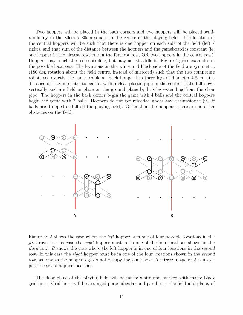
Two hoppers will be placed in the back corners and two hoppers will be placed semi-randomly in the 80cm x 80cm square in the centre of the playing field. The location ofthe central hoppers will be such that there is one hopper on each side of the field (left /right), and that sum of the distance between the hoppers and the gameboard is constant (ie.one hopper in the closest row, one in the farthest row, OR two hoppers in the centre row).Hoppers may touch the red centreline, but may not straddle it. Figure 4 gives examples ofthe possible locations. The locations on the white and black side of the field are symmetric(180 deg rotation about the field centre, instead of mirrored) such that the two competingrobots see exactly the same problem. Each hopper has three legs of diameter 4.8cm, at adistance of 24.8cm centre-to-centre, with a clear plastic pipe in the centre. Balls fall downvertically and are held in place on the ground plane by bristles extending from the clearpipe. The hoppers in the back corner begin the game with 4 balls and the central hoppersbegin the game with 7 balls. Hoppers do not get reloaded under any circumstance (ie. ifballs are dropped or fall off the playing field). Other than the hoppers, there are no otherobstacles on the field.
A B
Figure 3: A shows the case where the left hopper is in one of four possible locations in thefirst row. In this case the right hopper must be in one of the four locations shown in thethird row. B shows the case where the left hopper is in one of four locations in the secondrow. In this case the right hopper must be in one of the four locations shown in the secondrow, as long as the hopper legs do not occupy the same hole. A mirror image of A is also apossible set of hopper locations.
The floor plane of the playing field will be matte white and marked with matte blackgrid lines. Grid lines will be arranged perpendicular and parallel to the field mid-plane, of
11

width 1+/-0.3 cm and spaced 20cm centre-to-centre from the centre point of the field. Thecentre line will be red instead of black.
2.3 Gameplay Operation
Each robot begins in the 40cm x 40cm square that is against the back wall and on the redcentreline of their side of the playing field. A black or white marking will be present nearthe start position for the robot to be able to determine which side of the board it is playingon. Orientation is at the player’s discretion. Each team will be randomly assigned a colour3 minutes prior to the start of the game. Upon game start, the player initiates operation ofthe robot.
Both robots will have 7-minutes of simultaneous play. The game ends after 7 minutes orwhen the gameboard is full. Each robot will need to collect balls from hoppers distributed ontheir half of the field and play them from their side of the game board at centre. Frequencyof play is limited only by the performance of each robot, and is not turn-based. A ball maybe played in any one of the 7 columns, and will drop to the lowest available position in thatcolumn (whether it be column-bottom or on top of another ball). Once a ball has beenplaced in the gameboard it may not be removed by either player, with the penalty beingdisqualification for the round. If opponents balls are removed they will be replaced by theoverseeing Teaching Assistant as soon as possible.
Robots, however, may not intentionally control more than one gameballs at a time.Control is defined as either touching through direct or indirect contact, or using some near-field manipulation (such as air currents) to move a ball in a desired direction. Rolling aball along the field (in the hopes of recovering it later) is not considered control once theball has been released, but touching multiple balls when trying to corral them later wouldbe disallowed. Intentional is defined as a deliberate action: a robot will not be penalizedif it accidentally runs into a gameball that is rolling around the field. The exception iswhen pulling a ball from the hopper when the robot might come in contract with the ballabove, and sensing the gameboard, where the robot might touch multiple balls, but not inan attempt to move them. Anything that that the team places on the field is considered partof the robot and governed by these rules. Intentional control of multiple gameballs resultsin disqualification for the round.
Robots my not Intentionally interfere with opposing robots. Deliberately launchinggame balls to the opponents side of the field is disallowed, but unintentionally losing a ballto the other side is not penalized. If a balls falls into the opponents side of the field it willbe removed by the overseeing Teaching Assistant as soon as possible. Using fans or otherdevices near the gameboard that intentionally make it difficult for the opponent to play aball is disallowed.
In order to avoid interference at the gameboard the following rule applies: No part ofthe robot, at any time, may cross the centreline of the field or be positioned such that aball cannot be easily deposited into any column of the gameboard by a human hand. Thiseffectively results in the an envelope restriction shown in Figure ??, but also included theuse of air currents or other devices to interfere with the opponent’s play. Positioning a robotin such a way as to break this rule, at any point in the game, results in disqualification forthat round.
12
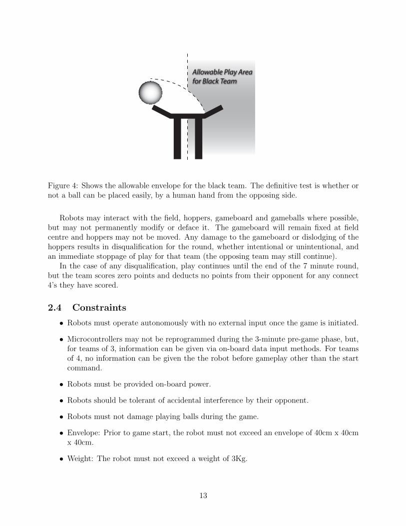
Allowable Play Areafor Black Team
Figure 4: Shows the allowable envelope for the black team. The definitive test is whether ornot a ball can be placed easily, by a human hand from the opposing side.
Robots may interact with the field, hoppers, gameboard and gameballs where possible,but may not permanently modify or deface it. The gameboard will remain fixed at fieldcentre and hoppers may not be moved. Any damage to the gameboard or dislodging of thehoppers results in disqualification for the round, whether intentional or unintentional, andan immediate stoppage of play for that team (the opposing team may still continue).
In the case of any disqualification, play continues until the end of the 7 minute round,but the team scores zero points and deducts no points from their opponent for any connect4’s they have scored.
2.4 Constraints
• Robots must operate autonomously with no external input once the game is initiated.
• Microcontrollers may not be reprogrammed during the 3-minute pre-game phase, but,for teams of 3, information can be given via on-board data input methods. For teamsof 4, no information can be given the the robot before gameplay other than the startcommand.
• Robots must be provided on-board power.
• Robots should be tolerant of accidental interference by their opponent.
• Robots must not damage playing balls during the game.
• Envelope: Prior to game start, the robot must not exceed an envelope of 40cm x 40cmx 40cm.
• Weight: The robot must not exceed a weight of 3Kg.
13

• Budget: The cost (as-purchased) of all components and materials utilized in fabricatingthe robot must not exceed $250CAD.
• Robots must have a safely-accessible STOP button that ceases robot operation imme-diately.
• The final robot must use properly soldered electronics and may not contain any bread-boards.
2.5 Scoring
1 Point is awarded for each ball played in the gameboard. In addition, 4 points are awardedfor each line of 4 or more balls (called a set), and 2 points are subtracted for each line of4 that is scored by the opponent, with the limit that your score may not be lower than thenumber of balls you have placed in the gameboard. A line of 5, 6 or 7 balls earns the extrapoints for a completed set, but only counts as one single set. Examples are given in Figure5. The full tournament structure is described in Section 3.6.2.
White: 9 Balls + [4x(3 Sets)] = 21 PointsBlack: 6 Balls - [2x(3 Sets)] = 6 Points
White: 5 Balls + [4x(1 Set) - 2x(1 Set)] = 7 PointsBlack: 5 Balls + [4x(1 Set) - 2x(1 Set)] = 7 Points
White: 17 Balls + [4x(11 Sets) - 2x(1 Set)] = 59 PointsBlack: 6 Balls + [4x(1 Set) - 2x(11 Set)] = 6 Points
Figure 5: Various examples of how to score the gameboard. If the value within the squarebrackets is less than zero, it is considered to be zero so that your score may never be lowerthan the number of balls deposited.
2.6 Design Criteria of Solution
This environment has been constructed to reward excellent engineering design, good proto-typing, and the use of strategy in gameplay. An optimal solution will give consideration toeach of the following desirable qualities:
• Robustness & reliability
• Tolerance of uncertainty in the environment
• Elegance & aesthetics
• Speed & manoeuvrability
14

• Effective use of resources
• Cost
• Safety
• Portability
2.7 Statement of Work
Each team will be composed of three team members (more or less when necessary, at theinstructors’ discretion). Frequent communication is strongly advised between team members,to expedite and improve the integration process. Generalist knowledge is also encouragedin order to help fellow team members overcome challenges and obstacles. A suggested workbreakdown is as follows:
Electromechanical Member: This member should be responsible for the overall hardwarefabrication and integration of the robot. This includes the robot frame and mobility compo-nents, mechanical components and actuators, and fixtures for all of the circuits/sensors andmicrocontroller elements.
Circuits & Sensors Member: This member should be responsible for the electrical compo-nents of the system, including design/fabrication/integration of circuits for driving actuators,sensors for awareness of the environment, and power supply/distribution.
Microcontroller Member: This member should be responsible for the programming ofthe Arduino microcontroller and interfacing with inputs/outputs of the robot. The Arduinoprogramming will heavily focus on system operation and autonomy, as well as gameplaystrategy.
15

3 Marking Scheme
3.1 Grading Outline
Each student’s final grade is based on the sum of team and individual evaluations, with atotal split of 62.5% team, 37.5% individual. The relative value of each evaluation as well asthe team/individual split is given in the table below:
Week Evaluation % Grade Team % Individual %
4 Project Proposal 15 80 205 Notebook I 7.5 0 1006 Progress Evaluation I 15 25 759 Progress Evaluation II 15 50 5012 Progress Evaluation III 15 75 2514 Design Competition 10 100 014 Notebook II 7.5 0 10014 Final Report 15 70 30
3.2 Budget Cap
A budget cap of $250 is set for team’s final machines. The purpose is to provide a level playingfield regarding the purchasing of pre-assembled or higher-level components, to minimize theamount of money the students must spend, and to encourage design and construction frommore fundamental building blocks.
• Adherence to the budget cap must be demonstrated in the Final Report and supportedwith a collection of all project receipts.
• The budget cap includes all components, materials and services that are used in theconstruction of the final machine, including shipping costs.
• Prices include taxes.
• If materials are donated, a fair market value must be included.
• Cost of specialty process, performed by others must be included even if labour wasdonated.
• Components purchased for the project, but not included on the final machine are notincluded.
• Exceeding the budget results in disqualification from the competition.
16

3.3 Project Proposal
The Project Proposal describes the conceptual design process and gives a detailed descriptionof the proposed design. All sections of the Proposal are given a team grade, except in theprototyping and specifications sections where each student will also receive an individualgrade.
The Proposal contains a maximum of 25 pages of text (single space, 12pt), in addition to10-25 pages of tables, figures and sketches. The use of appropriate figures, accompanied byclear and concise text is paramount when trying to convey your work to the person gradingyour proposal. Proposals are to contain the sections outlined below, with the associatedgrading rubric, and are to be submitted online via Blackboard as a single PDF document.
(3%) Title Page and Executive Summary
The Title Page includes team members names, team number, submission date, instructorand teaching assistant names, project title and any other critical information.
The Executive Summary, no more than one page in length, provides the reader with abrief overview of the proposal. It is designed to prompt the reader for what is to follow andto convince the reader that the proposed solution, and the process that led to the selectionof that solution, is sound.
(10%) Problem Formulation, Metrics and Values
This section gives a summary of the problem to be solved including specific quantifiablemetrics that will result in a winning solution. It also outlines individual values that guide thepriorities of the design, if for example the team values uniqueness, modularity, repairabilityor robustness.
(12%) Background Survey
The Background Survey contains a summary of the use of existing technologies in similarapplications. The survey should demonstrate a clear understanding of the relevance of agiven technology to the specific challenge.
(12%) Familiarization
Students will demonstrate working examples of various integrated sensors and actuatorsusing components from the project kit. Each working example will be demonstrated to theteam’s Teaching Assistant in the weeks leading up to the submission of the proposal, but thegrading will be based on the written component in this section. The section should includea brief description what was done and demonstrate a working understanding of the benefitsand drawbacks of the various actuators and sensors that were tested, as well as any otherinsights or lessons learned in the process.
17

(12%) Conceptualization
The Conceptualization section includes a description of both the process and the results ofa formalized idea-generation strategy, including any brainstorming diagrams, sketches anddiscussions of alternate solutions. Rough sketches or hand-written charts are preferred overformal CAD drawings at this point. The selection methodology used in the convergent designphase should be clearly outlined, with appropriate diagrams or charts.
It is crucial in this section to identify the most challenging or innovative aspects of design.This is critical in determining if your timeline and budget are feasible, as well as providingthe basis for Key Innovation section in the Progress Evaluations.
(20%) Prototyping [50% Team/50% Individual]
The Prototyping section describes the methodology and the results of the early testing thatled to the selected design. Prototyping could include simple cardboard models of variousmanipulators, structures, or anything that helps give a physical, 3-dimensional sense ofthe component. Results include a discussion of the lessons learned or insights gained fromthe prototype. Similar to the Conceptualization section, prototypes will be shown to theTeaching Assistants in the weeks leading up to the proposal submission, but the grade willbe based on the written content.
(20%) Specification of Proposed Design [50% Team/50% Individual]
This section should be divided into a system level functional description that will be gradedon a team basis and a sub-system level physical description which will be graded on anindividual basis.
The system level section gives a top level description of the components and how theyinteract. It specifies what is unique about your solution, and it addresses the metrics andvalues outlined in the Problem Formulation.
The sub-system level sections give the complete technical details of each system. Theyinclude detailed pseudo code, block diagrams, circuit diagrams and sketches of mechanicalcomponents. Again, sketches are preferred to CAD drawings at this stage. They include adetailed list of the specific components, hardware and material to be used and address howthe selected components will achieve the specified metrics and values.
(8%) Project Management
This section outlines the schedule, division of labour, and budget for the project.The schedule gives a breakdown of tasks and a timeline for the project, including clearly
identifiable weekly milestones to be used as a baseline for grading during Progress Evalu-ations. It is encouraged to use a Gantt chart or some other visual representation and toensure that the schedule aligns with the requirements of the Progress Evaluations.
The division of labour for the project should be made clear, assigning tasks to individualteam members in a clear manner that can be used to help guide Progress Evaluations.
18

The budget gives a breakdown of the costs of the final machine, demonstrating that theproposed solution is possible within the budget cap. A simple table with a brief explanationshould be sufficient.
(3%) Conclusion
Conclude the proposal with a summary of the proposed project and the methodology thatled to the proposed solution. Highlight key areas that make the project unique, innovative,and ultimately successful. Highlight key challenges and bottlenecks and how they will beovercome. Overall, convince the reader that you have a winning project.
3.4 Progress Evaluations
The Progress Evaluations are geared towards early integration of components. With thisgrading system, students will earn more points by having a few fully functional components,rather than completed sub-systems that are not yet integrated. The goal is to gain earlyexperience with the often-underestimated challenges of integration, and to use that expe-rience to improve the process for subsequent components. From Progress Evaluation I toProgress Evaluation III the marking shifts from 25% Team, 75% Individual to 75% Team,25% Individual.
Progress Evaluations take the form of a demonstration to the Teaching Assistant duringthe scheduled lab period. It is the responsibility of the students to present their components,prototypes, tests, and improvements in a clear manner that gives a complete understandingof the work, correlates directly to the marking scheme, and therefore result in the bestpossible grade.
3.4.1 Progress Evaluation I
At this stage, all analysis is complete (anything missing from report should be demonstrated)and all components are purchased. Notable progress on the key innovations and challenges isdemonstrated through advanced prototypes or tests, and one functioning component that in-tegrates all three sub-systems is demonstrated to the Teaching Assistant. It is advised to pickone of the easier components to gain experience as you progress to the harder components.
(30%) Demonstration of Selected Component [50% Team/50% Individual]
Demonstrate one integrated component, controlled autonomously by the microcontroller.The component should ideally combine a sensor and an actuator to give experience witha complete autonomous control loop (ie. Tripping of a sensor results in the mechanicalactuation of the component). At this stage circuits can be implemented on a breadboard.
(20%) Progress on Key Innovation or Challenge [50% Team/50% Individual]
Demonstrate and discuss prototypes or test results in the development of the key innovationsand challenges. Students should demonstrate an ability to learn from prototyping to expandon the original concept and find novel solutions.
19

(15%) Component Acquisition and Debugging Framework [Individual]
Show that all components have been acquired and that analysis to justify the componentselection is complete. In addition, for the Microcontroller member, an effective debuggingenvironment must be developed using a serial connection, Processing code, LCD display orsome other system.
(15%) Preparation, Focus & Dedication [Individual]
This involves arriving at the lab session prepared with necessary materials and components,arriving and packing up on time, and working in an efficient and organized manner. It alsoinvolves each team member’s contribution to group, including taking responsibility for anappropriate workload, and their role in causing or resolving group disharmony.
(5%) Skills Development [Individual]
Skill Development involves recognizing the need for new skills and demonstrating a continuedimprovement in craftsmanship, efficiency, and the ability to produce functional and robustcomponents, circuits or code.
(5%) Ability to Recognize and Solve Problems [Individual]
This involves taking care to think through problems thoroughly, recognizing and avoidingmajor pitfalls before construction. It also involves recognizing unforeseen problems whenthey do arise, and adapting the design to solve the issue. Students should be applying theirown experience as well as feedback from the Teaching Assistants appropriately to navigatedifficult challenges.
(5%) Safe Work Habits [Individual]
Demonstrate safe work habits, being aware of possible damage to equipment and people,including safe practices with tools and in the machine shop, damage to equipment fromimproper use, and damage to components from static shocks or applied voltages.
(5%) Care in Organization [Individual]
Demonstrate care in commenting code, labeling wires, organizing materials and components,and in general, habits that reduce the risk of bugs, mistakes, and lost time.
3.4.2 Progress Evaluation II
For the second Progress Evaluation teams should be able to demonstrate multiple workingcomponents and the use of the system components to complete higher level tasks. Progresson the key innovations and challenges should be demonstrated by a mostly-functioning firstiteration of the identified components.
20

(40%) Demonstration of Functioning Components [50% Team/50% Individual]
The students will setup the robot to complete as many of the following automated tasks.For debugging purposes it is recommended to test and demonstrate tasks separately. It isthe student’s responsibility to set up the task and to clearly demonstrate that the task hasbeen completed. If the robot get’s stuck, needs assistance, or needs to try several times thisis acceptable to within reason.
Each of the following tasks will be graded separately and given a score out of 5 with apossible total of 40. The resulting grade for this section will be multiplied by 2, with theconstraint that the marks for this section cannot exceed 40. This implies that the robotmust be able to complete roughly half the tasks for Progress Evaluation II.
At this point circuits may still be implemented on the breadboard.
1. Controlled locomotion: the robot must move between two given coordinate locationson the gameboard. The coordinates may be hard-coded in advance.
2. Picking up a gameball : with the robot aligned to the hopper, demonstrate that it canpick up and hold onto a gameball.
3. Placing a gameball : with the robot aligned to the game board, demonstrate that itcan place a gameball in a specific column of the gameboard.
4. Navigating to the gameboard : from a known location that is not directly in front ofthe gameboard, demonstrate that the robot can locate, move to, and align itself withthe gameboard, ready to place a gameball. Partial points are given for simply sensingthe gameboard, and for moving to the gameboard, but without proper alignment. Noobstacles (ie. hoppers) need be present in this task.
5. Navigating to a hopper : from a known location that is not directly in front of thehopper, demonstrate that the robot can locate, move to, and align itself with a hopperof known location, ready to pick up a gameball. Partial points are given for simplysensing the hopper and for moving to the hopper, but without proper alignment. Noadditional obstacles (hoppers) need be present in this task.
6. Moving around an obstacle: the robot must move between two given coordinate loca-tions, given an obstacle (hopper) of known position lying in its path. The position ofthe obstacle (hopper) can be hardcoded in advance as an (x,y) point or region, but therobot must autonomously compute it’s own path.
7. Locating an obstacle: For teams of 3, demonstrate that the location of the obstacles(hoppers) can be entered into the memory of the robot without re-programming themicrocontroller. For teams of 4, with the robot in the vicinity of an obstacle (hopper),sense the location of the obstacle and record its position in the robot’s memory.
8. Demonstration of gameplay strategy : demonstrate a strategy of placing game pieces.Full points will be awarded for a robot that can sense the state of the gameboardand play strategically according to the moves of the other player. Partial points willbe awarded for strategies that involve less sensing or are not as robust to misplaced
21
balls, overflowing columns, or other unknowns during gameplay. If the robot is capableof many of the above tasks this could involve playing a full game, with the studentsplacing game pieces by hand for the opponent. If this is not fully possible the robotmay receive assistance with picking up balls, but not with depositing them.
(20%) Progress on key innovation / challenges [50% Team/50% Individual]
Demonstrate a first iteration of the components that have been identified as the key inno-vations and challenges. The components should be mostly functioning, but still in need ofsome refinement. Discuss the results of testing as well as further improvements that needto be made, demonstrating an ability to learn from prototyping to expand on the originalconcept and find novel solutions.
(10%) Teamwork [Team]
Teams should demonstrate effective communication when discussing design ideas, includingeffective use of team members to give feedback and new ideas to each other’s subsystems.Teams should also demonstrate the ability to resolve disputes, maintain a pleasant workingenvironment, and adhere to proper conduct outside of lab hours when working in sharedpublic spaces.
(5%) Load Distribution [Team]
The workload should be distributed evenly and appropriately to make use of team membersindividual strengths.
(5%) External Interactions & Communication [Team]
Teams should interact effectively with the Teaching Assistant and have an awareness of theactivity of other teams around them.
(10%) Preparation, Focus & Dedication [Individual]
See Progress Evaluation I.
(2.5%) Skills Development [Individual]
See Progress Evaluation I.
(2.5%) Ability to Recognize and Solve Problems [Individual]
See Progress Evaluation I.
(2.5%) Safe Work Habits [Individual]
See Progress Evaluation I.
22
(2.5%) Care in Organization [Individual]
See Progress Evaluation I.
3.4.3 Progress Evaluation III
For Progress Evaluation III, teams should be able to demonstrate a complete a fully capablerobot. The focus should now be shifting to robustness, reliability and the improvement ofkey metrics.
(40%) Demonstration of Complete System [Team]
Setup the robot to play a full game with the students placing pieces by hand to simulatean opponent. If this is not possible, a subset of the tasks may be completed, but the teamsshould still try to combine multiple subtasks in their demonstration. If the robot gets stuck,needs assistance, or needs to try several times, this is acceptable to within reason. Pointsfor reliability and robustness are given separately in the next section.
Each of the tasks outlined in Progress Evaluation III will be graded separately and givena score out of 4 with a possible total of 40. This time, the resulting score will not bemultiplied, implying that the robot must be able to complete 100% of the tasks to receivethe full 40 marks.
Key innovations and challenges should be overcome at this point and are graded simplyas part of the completed system.
(10%) Reliability and Robustness [Team]
Points will be awarded here if the robot can complete the sequence of tasks in the demon-stration above consistently and without assistance. Physical robustness of the device will beevaluated based on the fragility of the structural frame, exposed sensors and actuators, andthe electrical and mechanical connections.
(10%) Improvements [50% Team/50% Individual]
Components should be in a more finished state, including soldered circuits and proper mount-ing of electronics.
In addition, tasks that were completed for the previous evaluation should show improve-ment in reliability, speed, strategy, weight or some other key metric. Students should keepdocumentation of the improvements in key metrics as evidence to show to the TeachingAssistants.
(10%) Teamwork [Team]
See Progress Evaluation II.
(5%) Load Distribution [Team]
See Progress Evaluation II.
23

(5%) External Interactions & Communication [Team]
See Progress Evaluation II.
(10%) Preparation, Focus & Dedication [Individual]
See Progress Evaluation I.
(2.5%) Skills Development [Individual]
See Progress Evaluation I.
(2.5%) Ability to Recognize and Solve Problems [Individual]
See Progress Evaluation I.
(2.5%) Safe Work Habits [Individual]
See Progress Evaluation I.
(2.5%) Care in Organization [Individual]
See Progress Evaluation I.
3.5 Notebook Evaluations
Students will maintain an engineering notebook throughout the course, as a useful organi-zational tool and as a complete record of the design process. Notes should be dated, andbound in a robust physics-type notebook. It is highly recommended to write in pen, but notstrictly necessary. If, however, pencil is used and smudges to become illegible, marks will bededucted. The notebooks will be evaluated twice during the semester, once during the labsession in week 5, and once at the end of the project when the lab kits are returned.
Notebooks should be neatly organized with a name and table of contents at the front,and at the back, useful sections similar to the following:
• Contact information: written info or taped-in business cards for people and suppliers.
• References to any books, notes or papers used during the project.
• References to any websites used during the project.
• Envelope glued to the back to keep project receipts.
It is likely that some of these sections would be better severed with digital solutions,but for ease of grading, and to further encourage the daily use of a design notebook, allinformation should be maintained in the physical notebook.
The body of the notebook contains day-by-day entries including brainstorming, back ofthe envelope calculations, sketches, tasks lists for the lab session, and any other thoughts
24

or ideas related to the project. The source of inspiration for various design ideas, circuits,analytical models, or components should be properly referenced, with the full referenceinformation given in the references section at the back.
In addition to a physical notebook, teams should implement an organized system forsharing electronic documents between team members.
(10%) Organization
Sections in the notebook should be clear, with the use of page numbers, dates, directoriesand a table of contents to help navigate the material.
(55%) Technical Content
Technical Content includes ideas, sketches, flow diagrams, sample calculations and pseudocode, written in such a way that the reader can follow the process of design, construction, andtesting. Any experimentation should be described as such, with a clear purpose, methodologyand summary of the results and conclusions. Content from the lectures may also be includedhere, but this is not strictly necessary.
(15%) Schedules and Task Planning
An overview of the project timeline should be present, along with revisions to the plan andan ongoing indication of whether or not tasks are on track. Day to day organization shouldbe present in the form of task lists or priorities that help the students maintain focus andefficiency. Notes from team meetings should also be present.
(10%) References
Reference information should be maintained in the back sections of the notebook for impor-tant companies, contacts and resources.
(5%) Receipts
Receipts should be kept with the notebook throughout the course.
(10%) Electronic Documents
Electronic documents and references should be kept organized using a system that can beshared and accessed by all team members. Teams must ensure that the Teaching Assistantshave access to the shared electronic resource in order to receive a grade.
3.6 Design Competition
The final design competition will be an exciting day of head to head competition, but it isalso a public demonstration, and teams should be ready to present their robots to visitors.Each team will be given a small display table that they can decorate with a team logo,pictures, poster or anything else they wish to use to distinguish their team and project.
25

Fairness and sportsmanship in competition is also highly valued and will receive a portionof the grade.
The competition is held during the last week of classes, during the regularly scheduledlab period. Teams compete only against other teams in their lab section.
3.6.1 Preliminary Competition
In the week before the competition, each team will have the opportunity to demonstrate thefunctionality of their robot in the Preliminary Competition. The preliminaries will be usedto determine the seeding of the tournament, but will also be used as a fallback for gradingin the event that the robot fails to function on the demonstration day.
Each team will have 7 minutes to place as many game pieces as possible into the gameboard. There will be no opponent, and the final score is purely the number of game piecesdeposited.
3.6.2 Competition Evaluation
Scores from the preliminaries yield an initial ranking. The competition starts with threeladder rounds that allow teams to compete against similarly ranked teams, followed by asingle elimination tournament for the top 8 teams.
In the ladder rounds teams pair off 1st vs. 2nd, 3rd vs 4th, etc., according to their rank.At the end of each round, each team’s score is added their cumulative total, a new ranking isformed, and the process repeats. If there are an uneven number of teams, the last place teamcompetes unopposed, earning points based only for the number of game pieces deposited (ie.no extra points for a connect four). Ties in the ranking are broken by random selectionusing a simple computer script.
After three ladder rounds the top 8 teams compete in a single elimination tournamentthat pairs 1st vs. 8th, 2nd vs. 7th, etc. The winner is crowned ultimate champion.
The final score for each team is their cumulative total from the preliminaries, ladderrounds and tournament.
(80%) Competition
If 0 points are scored, up to 25% of this grade can be given for partial functionality. Scoringany number of points will result in a percent grade of:
Grade = 25 + 75
√score
scoremax
(1)
(10%) Sportsmanship
Good sportsmanship involves acting with respect, encouraging the success of other teams,sharing tools, knowledge, or parts within the spirit of good competition. It is important tobe aware of your team’s conduct as not to interfere with the preparation or display of otherteams.
26

(10%) Presentation
Each team will have the opportunity to set up a display table with their robots and anyadditional material they see fit. Teams should make themselves available to present theirwork to visitors, and to answer questions about the project. As part of the evaluation,students will be asked to describe their robot, in 1-2 minutes, to one of the Instructors orTeaching Assistants and answer questions regarding its design and construction.
3.7 Final Report
The Final Report gives a summary of the design process as well as the final technical andoperational details of the machine, and recommendations for improvements and future work.All sections of the Final Report are given a team grade, except in the Technical Descriptionand Implementation sections which contain an individual component. The sections beloware given as a starting point, but can be broken down into more specific subsections thatgive clarity and organization to the report.
The Final Report contains a maximum of 40 pages of text (single space, 12pt), in addi-tion of 20-40 pages of tables, figures and drawings. It is critical that the report is organizedand written in a clear manner that can be easily understood by someone unfamiliar withthe work. Concise text and the use of appropriate figures is crucial to good communication.Reports should be written in the third person, past tense, objectively without embellish-ment, exaggeration or opinions that lack technical support. Proposals should be organizedaccording to the sections outlined below, and submitted online via Blackboard as a singlePDF document.
(10%) Preamble Sections [Team]
The Preamble refers to the collection of sections at the beginning of the report including:title page, team photograph, acknowledgments, table of contents, symbols and abbreviationsand the executive summary.
The title page includes team members names, team number, submission date, instructorand teaching assistant names, project title as well as a team logo, drawing, photo or otheruseful graphics. A photograph of the team and the robot should be included after the titlepage.
Acknowledgements provides an opportunity to thank anyone that has helped you withthe project. The table of contents, list of symbols and abbreviations should be complete andorganized for quick reference.
The executive summary, no more than one page in length, provides the reader with anoverview of the report. It is designed to prompt the reader for what is to follow, give a senseof the complete design and construction process, and summarize the results and conclusionsof the project.
(15%) Design Process [Team]
This section can be viewed as a trimmed down version of the Design Proposal, but from anew perspective of having implemented the proposed solution. This section should contain
27
the following topics or sub-sections:Introduction: gives context to the entire project, clearly outlining the objectives and
constraints.Metrics and Values : the methodology that turns the objectives into a clear set of design
metrics.Background : summary of background research at the system and sub-system level.Conceptualization: description of the ideation process, both divergent brainstorming
phase, as well as the convergent design phase including any formal decision making strategiesor charts.
(30%) Technical Description [50% Team/50% Individual]
The Technical Description contains a clear and exhaustive descriptions of the entire system.It should be broken into a system level description and a sub-system level description.
The system level description should give a functional understanding of the robot and theinteraction of all of the sub-systems. In addition it should include a section with the fulloperating procedure of the robot, including pre-flight and post-flight check lists.
The sub-system level description should give the full technical details of each componentof the machine. The description should be supported by calculations, computer programs orsimulation results that present a complete technical picture of the implemented design.
(30%) Implementation [50% Team/50% Individual]
The Implementation section outlines the process of construction and integration of the threesub-systems, highlighting the differences between the theoretical design and it’s practicalimplementation. It should be broken down into a system level discussion and a sub-systemlevel discussion.
The sub-system discussion should give the results of component testing, providing adirect comparison between the design calculations and the final result. It should describethe major obstacles encountered in the construction process, and changes that were madeduring implementation. Possible improvements in the sub-systems should also be discussed,including alternative component selection, design concepts or changes in the construction.
The system level discussion describes the integration process for each of the componentsas well as testing procedure and refinement process for the entire system. Tests and refine-ments may include debugging non-functional components as well as testing and improvingspecific key metrics outlined in the Proposal. The section should also give a detailed accountof the key innovations outlined in the Proposal, including how they were tested and refinedthroughout the course. This is an opportunity to reflect on the major obstacles involved inimplementing a given design and the differences between theory and practice. Include alsoa discussion of components that were not necessarily thought to be a major challenge orinnovation, and the process of their implementation. Improvements to the system shouldalso be discussed, focussing on system level changes or changes in the design if you had theopportunity to repeat the process.
28
(12%) Project Management [Team]
This section should include the project schedule, division of labour, and the final budget.The project schedule should include a comparison of the proposed and actual schedule,
highlighting key bottlenecks, obstacles or areas of unexpected success.The division of labour for the project should be made clear, showing the actual distribu-
tion of tasks.The budget is given here, clearly indicating the that team remained within the budget cap.
The budget includes only parts, materials and labour that are present on the final machineas outlined in Section 3.2. Supporting receipts must be submitted with the notebooks forthe final Notebook Evaluation.
(3%) Conclusions [Team]
The report should conclude with a summary of the project including the design methodol-ogy and the key areas that make the project unique. Highlight the results of the design’simplementation including performance metrics and competition results. Discuss elements ofthe project that went well, and elements that suffered from unforeseen challenges or compli-cations. Discuss suggestions for future work, design changes or team management changesthat would result in an even more successful project in the future.
3.8 Allocation of Team Marks
The default assumptions is the equal distribution of team marks amongst the team members.If, however, a member finds reasons that this distribution is not fair, an email may be sentto the instructor no later than April 13th. In this case the instructor will call all membersfor a meeting in which a percentage of the team mark will be assigned to each team member(where the percentages add up to 300% for a team of 3 students). All students will agreeand sign off on the new mark distribution.
29