aerospace material specificationallaboutmetallurgy.com/wp/wp-content/uploads/2016/03/… · ·...
TRANSCRIPT
SAE Technical Standards Board Rules provide that: “This report is published by SAE to advance the state of technical and engineering sciences. The use of this report is entirelyvoluntary, and its applicability and suitability for any particular use, including any patent infringement arising therefrom, is the sole responsibility of the user.”
SAE reviews each technical report at least every five years at which time it may be reaffirmed, revised, or cancelled. SAE invites your written comments and suggestions.
Copyright 1999 Society of Automotive Engineers, Inc.All rights reserved. Printed in U.S.A.
QUESTIONS REGARDING THIS DOCUMENT: (724) 772-7161 FAX: (724) 776-0243TO PLACE A DOCUMENT ORDER: (724) 776-4970 FAX: (724) 776-0790SAE WEB ADDRESS: http://www.sae.org
400 Commonwealth Drive, Warrendale, PA 15096-0001
AEROSPACE MATERIAL SPECIFICATION
Submitted for recognition as an American National Standard
AMS 2647B
Issued APR 1985Revised OCT 1999
Superseding AMS 2647A
(R)Fluorescent Penetrant Inspection
Aircraft and Engine Component Maintenance
1. SCOPE:
1.1 Purpose:
This specification details requirements and procedures for the detection of defects in aircraft and engine components during maintenance and overhaul operations.
1.2 Basis of Application:
This process has been used typically by maintenance and overhaul facilities to inspect aircraft and engine components and associated accessories when fluorescent penetrant inspection is specified, but usage is not limited to such applications.
1.2.1 There are areas in this document that may require specific direction from the OEM or cognizant engineering organization. This direction shall be provided in the part material specification for each part (see 8.2.47) in the following areas:
1.2.1.1 Etching Requirements: If not specified, etching will not be performed (See 3.4.5.1).
1.2.1.2 Cleaning Requirements: If not specified, solvent cleaning using Isopropyl Alcohol, Acetone or Methyl Ethyl Ketone (see 3.4) or an approved QPL AMS 2644 is acceptable.
1.2.1.3 Surface Coating Removal: If not specified, parts will be inspected with the surface coating intact (See 3.4.4 and 3.4.4.1).
1.2.1.4 Penetrant Sensitivity Level: If not specified, Sensitivity Level 3 penetrants shall be used on all airframe hardware and components and Sensitivity Level 4 penetrants shall be used on all Major Rotating Engine hardware and Auxiliary Power Unit hardware and components.
1.2.1.5 Pentrant Method: If not specified, Type I, Methods A, C or D penetrants may be used except for major rotating engine hardware which shall only be inspected using Type I, Methods C or D penetrants.
AMS 2647B SAE AMS 2647B
- 2 -
1.2.1.6 Developer: If not specified, dry developer (form a) will be used.
1.2.1.7 Inspection Coverage: If not specified, the areas described in 3.5.12 shall be inspected. If inspection of areas requiring special equipment or techniques (i.e. UV borescopes or light sources, special material application or removal devices, part handling fixtures, part masking, etc.) is necessary, detailed instructions must be provided. When specific areas of parts require intensified inspection scrutiny, due to either their critical nature or past history of failure, this information must be included in the repair or inspection manual or document.
1.2.1.8 Processing Parameters: Shall be as specified within this document. If approved by the OEM, different processing parameters, other than those specified herein, may be used.
1.3 Classification of Penetrant Systems:
Applicable fluorescent penetrant systems are classified into the following Methods and Sensitivity Levels:
Fluorescent dye
Method A: Water-WashableMethod B: Post Emulsifiable, LipophilicMethod C: Solvent RemovableMethod D: Post Emulsifiable, Hydrophilic
Sensitivity Level 2: MediumSensitivity Level 3: HighSensitivity Level 4: Ultra-high
NOTE: Developer forms are listed in 3.1.4.
1.4 Safety - Hazardous Materials:
While the materials, methods, applications, and processes described or referenced in this specification may involve the use of hazardous materials, this specification does not address the hazards which may be involved in such use. It is the sole responsibility of the user to ensure familiarity with the safe and proper use of any hazardous materials and to take necessary precautionary measures to ensure the health and safety of all personnel involved.
1.4.1 Safety Precautions: Protective clothing, including eye shields, suitable gloves, and aprons should be worn when filling tanks or when there is a possibility of splashing or overspray. Tanks should be covered when not in use and should be operated with adequate ventilation for fume extraction. Operating instructions from the manufacturer of the system employed together with local workshop regulations shall be followed.
AMS 2647B SAE AMS 2647B
- 3 -
2. APPLICABLE DOCUMENTS:
The issue of the following documents in effect on the date of the purchase order form a part of this specification to the extent specified herein. The supplier may work to a subsequent revision of a document unless a specific document issue is specified. When the referenced document has been canceled and no superseding document has been specified, the last published issue of that document shall apply.
2.1 SAE Publications:
Available from SAE, 400 Commonwealth Drive, Warrendale, PA 15096.
AMS 2644 Inspection Materials, Penetrant
2.2 ASTM Publications:
Available from ASTM, 100 Barr Harbor Drive, West Conshohocken, PA 19428-2959.
ASTM D 95 Water in Petroleum Products and Bituminous Materials by DistillationASTM E 1417 Liquid Penetrant Examination
2.3 U.S. Government Publications:
Available from DODSSP, Subscription Services Desk, Building 4D, 700 Robbins Avenue, Philadelphia, PA 19111-5094.
MIL-I-25135 Inspection Materials, PenetrantMIL-STD-410 Guide Lines for Training and Qualifying Personnel In Nondestructive Testing
MethodsQPL 25135 Inspection Materials, PenetrantQPL-AMS-2644 Inspection Material, Penetrant
2.4 ATA Specifications:
Available from Air Transport Association of America, 1709 New York Avenue, N.W., Washington, DC 20006.
ATA Specification 105 Guidelines for Training and Qualifying Personnel in Nondestructive Testing Methods
2.5 AIA Specifications:
Available from Aerospace Industries Association of America Inc., 1250 Eye Street N.W., Washington DC 20005.
NAS 410 Certification and Qualification of Nondestructive Test Personnel

AMS 2647B SAE AMS 2647B
- 4 -
2.6 ASNT Documents:
Available from ASNT, 1711 Arlingate Plaza, P.O. 28518, Columbus, OH 43228-0518.
ASNT-TC-1A Recommended Practice for Personnel Qualification in Nondestructive Testing
3. TECHNICAL REQUIREMENTS:
3.1 Materials:
Materials used (i.e. penetrants, emulsifiers, and developers) shall conform to MIL-I-25135 or AMS 2644 and be listed in QPL 25135 or in QPL-AMS-2644, and be approved by the original equipment manufacturer’s (OEM’s) part or material specifications.
3.1.1 Penetrant: Shall be a highly fluorescent liquid capable of penetrating discontinuities and with a sensitivity level as specified in the OEM’s part or material specification.
3.1.2 Lipophilic Emulsifier: Shall consist of a ready-to-use suitable oil-like liquid together with such additives as necessary to provide a stable, oil-miscible solution capable of being emulsified and rinsed away with water.
3.1.3 Hydrophilic Emulsifier: Shall be composed of surface-active agents together with additives. Emulsifiers shall be capable of dilution up to many times their volume in water to form stable aqueous solutions.
3.1.4 Developers: Applicable developers are classified into four forms.
Form a Dry Powder Developer Form b Aqueous Soluble Developer Form c Aqueous Suspendible DeveloperForm d Nonaqueous Wet Developer (NAWD)
3.1.5 Grouping of Materials: Penetrants and their emulsifiers shall be qualified and used as a “penetrant/emulsifier” system, furnished by one manufacturer to perform a specific method or process of penetrant inspection. Developers may be from a different manufacturer. Method A penetrants are not qualified with an emulsifier.
3.2 Equipment:
Shall be constructed and arranged to permit uniform, controlled operation. Quality control of equipment shall be as specified in Section 4.
AMS 2647B SAE AMS 2647B
- 5 -
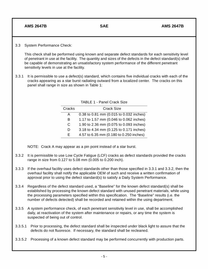
3.3 System Performance Check:
This check shall be performed using known and separate defect standards for each sensitivity level of penetrant in use at the facility. The quantity and sizes of the defects in the defect standard(s) shall be capable of demonstrating an unsatisfactory system performance of the different penetrant sensitivity levels in use at the facility.
3.3.1 It is permissible to use a defect(s) standard, which contains five individual cracks with each of the cracks appearing as a star burst radiating outward from a localized center. The cracks on this panel shall range in size as shown in Table 1:
NOTE: Crack A may appear as a pin point instead of a star burst.
3.3.2 It is permissible to use Low Cycle Fatigue (LCF) cracks as defect standards provided the cracks range in size from 0.127 to 5.08 mm (0.005 to 0.200 inch).
3.3.3 If the overhaul facility uses defect standards other than those specified in 3.3.1 and 3.3.2, then the overhaul facility shall notify the applicable OEM of such and receive a written confirmation of approval prior to using the defect standard(s) to satisfy a Daily System Performance.
3.3.4 Regardless of the defect standard used, a “Baseline” for the known defect standard(s) shall be established by processing the known defect standard with unused penetrant materials, while using the processing parameters specified within this specification. The “Baseline” results (i.e. the number of defects detected) shall be recorded and retained within the using department.
3.3.5 A system performance check, of each penetrant sensitivity level in use, shall be accomplished daily, at reactivation of the system after maintenance or repairs, or any time the system is suspected of being out of control.
3.3.5.1 Prior to processing, the defect standard shall be inspected under black light to assure that the defects do not fluoresce. If necessary, the standard shall be recleaned.
3.3.5.2 Processing of a known defect standard may be performed concurrently with production parts.
TABLE 1 - Panel Crack Size
Cracks Crack Size
A 0.38 to 0.81 mm (0.015 to 0.032 inches)B 1.17 to 1.57 mm (0.046 to 0.062 inches)C 1.90 to 2.36 mm (0.075 to 0.093 inches)D 3.18 to 4.34 mm (0.125 to 0.171 inches)E 4.57 to 6.35 mm (0.180 to 0.250 inches)
AMS 2647B SAE AMS 2647B
- 6 -
3.3.5.3 The system performance check shall be performed by processing the known defect standard through the facilities penetrant system using the processing parameters specified within this document.
3.3.5.4 The results of the system performance check shall be compared against the recorded “Baseline” results.
3.3.6 When the performance of the system performance check falls below that of the recorded “Baseline” results, the in-use materials shall be checked in accordance with the requirements of Section 4.
3.3.6.1 If it is suspected that the defect standard has deteriorated rather than the system, the standard should be recleaned and reprocessed or an alternate defect standard, which has been “Baselined” in accordance with paragraph 3.3.4, may be used.
3.3.7 Cleaning and Storage of the Defect Standard: To ensure independent, accurate results and to prevent clogging and contamination of the flaws, the known defect standards shall be cleaned and stored in accordance with manufacturer’s recommended instructions or as follows after each run:
3.3.7.1 Rinse the defect standard(s) with water using a maximum water pressure of 40 psi and, if necessary, use a soft bristle nonmetallic brush to remove residual developer. Hydro-air nozzles may be used. Blow off residual water spots with an air gun followed by drying the defect standard(s) in a hot air circulating dryer for approximately 20 minutes at a maximum of 71 °C (160 °F).
3.3.7.2 Immerse the cleaned and dried defect standard(s) in a cleaning solvent (e.g. Acetone, Methyl Ethyl Ketone, Isopropyl Alcohol, etc.) for a minimum of 10 minutes. Remove panel from the cleaner and allow to air dry or dry in an oven.
3.3.7.3 Store the defect standard in a clean container.
EXCEPTION: It is permissible to allow the defect standard(s) to remain submerged in the cleaning solvent (see 3.3.7.2) until it is ready to be used again. However, assure that the solvent is completely dried on the surface and in the defects of the standard prior to penetrant application.
CAUTION: If not cleaned or stored properly, the defect standards may become unusable due to contamination of the flaws.
AMS 2647B SAE AMS 2647B
- 7 -
3.4 Surface Preparation of Parts to be Inspected:
Proper surface preparation of parts for penetrant inspection is extremely critical. The primary objectives of the part preparation are to insure the discontinuity is clean, dry and open to the surface and that minimal fluorescent background is obtained after processing. Surface preparation, including cleaning, stripping, masking, blasting, peening, etching and drying, shall be accomplished using methods and materials specified in the OEM’s part or material specifications. If OEM guidance is not provided, the information in the following paragraphs shall be considered by the cognizant engineering organization (CEO) in preparing parts for inspection.
CAUTION: Visible or contrast dye penetrant shall never be used on a part prior to fluorescent penetrant inspection (FPI). Contamination from the visible dye can severely degrade the brightness of the fluorescent dyes.
3.4.1 General: Reliable penetrant inspections are highly dependent on proper pre-inspection processing. Because this is difficult or impossible for inspection personnel to determine or control, it is the responsibility of the CEO to include proper pre-inspection processing requirements in all work documents specifying the use of penetrant inspection. As a rule, any operation, which may prevent penetrant from entering defects, must be avoided.
3.4.1.2 Personnel accomplishing surface preparation such as cleaning must be properly trained so that they are fully knowledgeable with the operations they are performing, including both company and OEM specifications. They should also be aware of the impact that improper performance of their duties can have on both hardware and on subsequent operations such as fluorescent penetrant inspection (FPI).
CAUTION: Failure to properly clean prime reliable parts (e.g. disks, hubs, rotors, major rotating seals and spacers, etc.) can prevent the detection of flaws leading to a failure of these parts causing substantial damage and could potentially result in an uncontained failure and loss of aircraft.
3.4.2 Sequence of operations shall be as follows:
3.4.2.1 Penetrant inspection shall be performed prior to any operation which may close or smear openings or leave unremovable residue within a defect, such as plating, anodizing or surface cold working.
3.4.2.2 Penetrant inspection shall be performed subsequent to any operation that may introduce or expose defects such as, heat treatment involving quenching, welding, cold forming or grinding.
3.4.3 Cleaning: Areas of parts to be examined shall be free of moisture, grease, oil, grinding compounds, rust, scale, acids or alkalis, fluxes, burrs, feather edges, paint (primer, enamel), and other foreign materials which could hide defects or produce irrelevant indications that may interfere with the examination process.
AMS 2647B SAE AMS 2647B
- 8 -
3.4.3.1 Cleaning Methods: Cleaning methods chosen for a particular part shall be consistent with the type of contaminant to be removed and shall not be chemically detrimental to the part. Methods include solvent cleaning, steam cleaning, ultrasonic cleaning, vapor blasting, paint and carbon stripping, and alkaline or acid cleaning.
3.4.3.2 Cleaning methods must not leave a residue, which could interfere with the FPI process or potential subsequent repair operations.
NOTE: Halogenated/chlorinated solvents shall not be used on titanium alloys.
3.4.4 Plating or Surface Coatings: Coatings or surface treatments can prevent penetrant from entering defects as well as cause varying levels of fluorescent background on the part. High background fluorescence reduces the contrast between defect indications and background (signal to noise ratio) with a corresponding decrease in inspection sensitivity. With certain types of plating or coating, it may be possible to perform an adequate inspection providing the plating or coating is in good condition and the defect is open to the surface.
3.4.4.1 Conversion coatings impregnations, flame spray, plating or paint should be removed prior to penetrant inspection if an inspection with a high level of sensitivity is desired. Removal of these coatings must be specified in the work document. If not specified, it will be assumed that inspections are to be conducted with the coating intact. Removal of these coatings should not be done in a manner which may cause metal smearing, or which leaves chemical residue on the part that may contaminate defects.
3.4.4.2 Peening operations shall never be performed prior to penetrant application because the smearing and compressive stresses imparted by peening can completely eliminate the possibility of penetrant from entering a flaw.
3.4.5 Mechanical Surface Treatment: Surface treatment such as abrasive blasting, sanding and burnishing operations can produce a smeared surface on some materials. If it is necessary to perform any of these operations prior to penetrant inspection, it is good practice to accomplish an acid etch prior to inspection.
CAUTION: When employing one of the above surface treatments, it is important to follow the approved parameters, consumable materials and procedures as specified by the OEM’s specification for the particular part.
3.4.5.1 Etching can be detrimental to part function or serviceability. It is the responsibility of the CEO to make this determination and act accordingly. If the repair or overhaul document does not specify acid etch prior to inspection, it will not be accomplished. In all cases, only approved etching (cleaning) procedures and consumable materials specified by the OEM’s engine manuals for a specific part shall be permitted.

AMS 2647B SAE AMS 2647B
- 9 -
3.4.6 Drying: Failure to sufficiently dry a part after cleaning can affect the capillary action and prevent the penetrant from entering a flaw. Parts cleaned with an aqueous or slow drying solvent cleaner shall be “flashed dried” and/or dried at an elevated temperature to remove moisture from the surface and possible defects.
3.4.6.1 Flash dry parts by submerging the part in a tank of hot water or by hot water spraying. With either method, the water shall be heated to 66 to 93 °C (150 to 200 °F) and the part shall dwell (i.e. remain submerged or sprayed) until the temperature of the part reaches the water temperature. Remove the part from the tank and drain excess water. Utilize repositioning, suction, blotting with a clean absorbent material, or by blowing off with an oil and water filtered shop air gun to remove excess water.
CAUTION: Dwell times will depend upon the number of parts in a basket and the size and mass of the part being heated. Proper flash drying is indicated by seeing the water on the surface of a part start to “flash” or “whisk” off as the part is being removed from the hot water tank.
3.4.7 Masking: Parts inspected using the penetrant method shall receive 100% inspection coverage except that, parts having riveted doublers, data plates, air seals, rubberized coatings or other areas which may entrap penetrant and which are not removed as part of the normal process will not receive inspection in the areas where excessive bleed out of the penetrant prohibits it. If inspections of these areas are required, removal and/or masking must be specified in the applicable repair or inspection document.
3.4.7.1 Removal of anti-friction bearings prior to penetrant inspection is recommended. If bearings are not removed, they should be completely masked prior to routing to FPI in order to prevent contamination by penetrant fluid.
3.5 Processing Procedures:
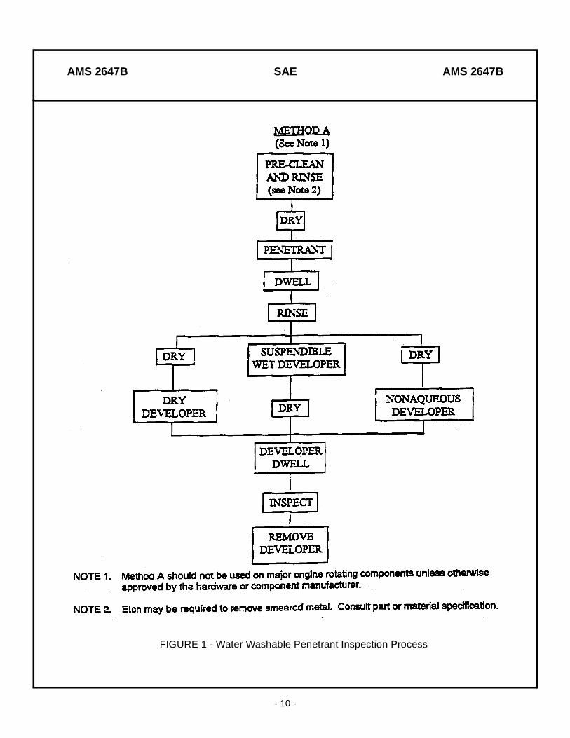
Descriptions of the different processing procedures are presented in Figures 1, 2, 3, and 4.
3.5.1 Visual Examination: Visually examine parts. Parts to be processed/inspected must be clean, dry and free of surface contaminants. Surface contamination can interfere with the capillary action of the penetrant and prevent the penetrant fluid from being drawn into a surface defect, thus compromising the FPI results. The goal is to get parts clean enough to perform a reliable inspection. Parts shall not be processed if they are considered insufficiently clean for FPI.
3.5.1.1 If you can remove contaminants (grease, oil, loose soils, etc.) with your finger or if the part has scale (hardened deposits), then the part is not sufficiently clean. If necessary, localized surface contamination may be removed using acetone, Isopropyl alcohol, methylethyl ketone or an approved QPL-AMS 2644 solvent cleaner/remover.
3.5.1.2 Parts must be fully dry before application of penetrant. If necessary, the surface may be heated to 107 °C (225 °F), (maximum) to remove moisture. The surface of the part must be cool to touch before penetrant application.
AMS 2647B SAE AMS 2647B
- 10 -
FIGURE 1 - Water Washable Penetrant Inspection Process

AMS 2647B SAE AMS 2647B
- 11 -
FIGURE 2 - Post Emulsifiable (Lipophilic) Penetrant Inspection Process

AMS 2647B SAE AMS 2647B
- 12 -
FIGURE 3 - Solvent Removable Penetrant Inspection Process

AMS 2647B SAE AMS 2647B
- 13 -
FIGURE 4 - Post Emulsifiable (Hydrophilic) Penetrant Inspection Process
AMS 2647B SAE AMS 2647B
- 14 -
3.5.1.3 Parts which show visible evidence or are suspected of having been contaminated with visible or contrast dye penetrant must be thoroughly cleaned to remove all traces of contamination as these dyes can severely degrade the brightness of the fluorescent penetrant.
3.5.1.4 Use of a black light during initial examination may help to identify the presence of contaminants. Many organic contaminants fluoresce blue under UV light.
3.5.1.5 The use of one higher penetrant sensitivity level from that sensitivity level specified for a given part is permissible.
3.5.2 Penetrant Applications for Methods A, B, C, and D:
3.5.2.1 Water washable (Method A) and postemulsifiable lipophilic (Method B) penetrant shall not be used on major rotating engine components.
3.5.2.2 Prior to penetrant application, the penetrant and part’s surface temperature shall be within the range of 4 to 52 °C (40 to 125 °F) if the surface of the part is cool to the touch, it shall be considered to be below 52 °C (125 °F).
3.5.2.3 Penetrant shall be applied by spray, immersion or brushing to provide penetrant coverage as required. Check for complete penetrant coverage with a blacklight.
3.5.2.4 If the penetrant beads up or separates when the penetrant is applied to the surface of the part, the part was not clean enough and must be recleaned.
3.5.2.5 Use not less than 20 minutes penetrant dwell/drain time.
3.5.2.6 Parts left to dwell longer than 2 hours shall have penetrant reapplied. If penetrant is reapplied the initial penetrant dwell time shall be repeated.
3.5.3 Water Washable Penetrant Removal (Method A):
3.5.3.1 Remove penetrant with a coarse spray rinse or an air agitated immersion wash tank.
3.5.3.2 Maximum water pressure shall be 275 kPa (40 psi). Hydro-air nozzles are permitted with a maximum of 170 kPa (25 psi) added air pressure.
3.5.3.3 When possible, the spray washing distance between part surface and the spray nozzle tip shall be not less than 305 mm (12 inches).
3.5.3.4 Spray or immersion washing time shall be held to a minimum. Wash time shall be held to not more than 90 seconds on any one area of a part. To assure the adequacy of the wash, the washing shall be conducted in a suitably darkened area under black light illumination.
3.5.3.5 Control water temperature within the range 10 to 38 °C (50 to 100 °F).
AMS 2647B SAE AMS 2647B
- 15 -
3.5.3.6 After washing, drain water from parts, utilizing repositioning, suction, blotting with clean absorbent material, or an air blow off using oil and water filtered shop air at less than 170 kPa (25 psi) to prevent pooling.
3.5.4 Pre-Rinse for Hydrophilic Emulsifier (Method D):
3.5.4.1 Spray rinse parts in the least possible time to remove excess penetrant from the part. Maximum wash time shall be held to 90 seconds on any one area.
3.5.4.2 Allow water to drain from the part. Reposition parts as necessary to aid in draining.
3.5.4.3 If necessary, use filtered shop air at a pressure less than 170 kPa (25 psi) or use a suction device to remove excess water from cavities.
3.5.4.4 Control water temperature within a range of 10 to 38 °C (50 to 100 °F) and a maximum pressure of 275 kPa (40 psi).
3.5.5 Application of Hydrophilic Emulsifier (Method D):
3.5.5.1 All surfaces to be inspected shall be completely covered in hydrophilic emulsifier solution during contact time.
3.5.5.2 Contact with the emulsifier shall be kept to the least possible time consistent with an acceptable background and shall not exceed two minutes.
3.5.5.3 In immersion systems, emulsifier and/or part shall be mildly agitated. If air or mechanical agitation is used, it shall produce no more than a thin layer of bubbles on the surface of the solution.
3.5.5.4 For immersion application, the concentration of the emulsifier solution shall be in accordance with 4.4.2.2.
3.5.5.5 For spray application, the concentration of the emulsifier solution shall be in accordance with 4.4.2.3.
3.5.6 Post-Rinse of Hydrophilic Emulsifier (Method D):
3.5.6.1 Emulsifier shall be removed by immersing the part in a water-filled, air-agitated tank followed by a spray touch-up rinse, or by spray rinsing.
3.5.6.2 Water temperature shall be controlled within a range of 10 to 38 °C (50 to 100 °F) and a maximum pressure of 275 kPa (40 psi). Hydro-air nozzles may be used with a maximum of 170 kPa (25 psi) added air pressure.
3.5.6.3 When possible, the spray washing distance between part surface and the spray nozzle tip shall be not less than 305 mm (12 inches).
AMS 2647B SAE AMS 2647B
- 16 -
3.5.6.4 Washing time shall be held to the minimum required to remove excess penetrant from the part. Wash time shall be held to not more than 90 seconds on any one area of a part.
3.5.6.5 After rinsing, drain water from parts utilizing repositioning, suction, blotting with a clean absorbent material, or an air blow off using oil and water filtered shop air at less than 170 kPa (25 psi) pressure to remove excess water and thus prevent pooling.
3.5.7 Application of Lipophilic Emulsifier (Method B):
3.5.7.1 Lipophilic emulsifiers are not acceptable for aircraft engine parts.
3.5.7.2 Apply by flowing emulsifier on the part or by dipping the part in emulsifier and letting it dwell for the required time. Lipophilic emulsifiers shall not be applied by spray or brush and shall not be agitated while in contact with the surface of the part.
3.5.7.3 Contact with emulsifier shall be kept to the least possible time consistent with an acceptable background and shall not exceed three minutes.
3.5.8 Post-Rinse of Lipophilic Emulsifier (Method B):
3.5.8.1 Water spray or immerse parts to remove emulsified penetrant. Maximum spray or immersion time shall be held to 90 seconds on any one area of a part.
3.5.8.2 Washing shall take place in a suitably darkened area under black light to confirm removal of fluorescent background.
3.5.8.3 After rinsing, drain water from parts utilizing repositioning, suction, blotting with a clean absorbent material, or an air blow off using oil and water filtered shop air at less than 170 kPa (25 psi) pressure to prevent pooling.
3.5.8.4 Water temperature shall be controlled within the range 10 to 38 °C (50 to 100 °F) and a maximum pressure of 275 kPa (40 psi).
3.5.8.5 When possible, the spray washing distance between part surface and the tip of the spray nozzle shall not be less than 305 mm (12 inches).
3.5.9 Local Application for Solvent Removable Penetrants (Method C):
3.5.9.1 Remove the excess penetrant by wiping with a clean, lint-free, dry cloth or absorbent toweling.
3.5.9.2 Remove the remainder of the surface penetrant with a lint-free cloth or towel, dampened with a QPL-AMS-2644 approved solvent. Ensure that the surface of the part and/or the cloth or towel is not saturated with solvent. During the wiping, the part and cloth or towel shall be observed under appropriate black light illumination to ensure adequate removal of surface penetrant. Excessive removal of the surface penetrant or flooding of the solvent on the surface of the part shall require the part to be cleaned, dried, and reprocessed.
AMS 2647B SAE AMS 2647B
- 17 -
3.5.9.3 The surface of the part shall be dried by wiping with a lint-free, dry cloth or towel or by evaporation.
3.5.10 Drying for Method A, B, and D:
3.5.10.1 Drying oven temperature shall not exceed 71 °C (160 °F).
3.5.10.2 Use minimum drying time to completely dry parts.
3.5.11 Developing: Use dry developer except where aqueous soluble/suspendible or nonaqueous wet developer (NAWD) is specifically required.
3.5.11.1 Parts shall not be exposed to blacklight radiation while developing.
3.5.11.2 Dry Developers can be used on Methods A, B, C, and D penetrants. Ensure parts are dry before applying developer.
3.5.11.2.1 Apply dry developer to a dry part so that all areas to be inspected are completely covered with a light coating of developer.
3.5.11.2.2 Allow part to develop for not less than 10 minutes before inspection.
3.5.11.2.3 Excessive powder may be removed after 10 minutes by blowing with dry air at pressure not greater than 35 kPa (5 psi).
3.5.11.2.4 Parts shall be cleaned and reprocessed if time after development exceeds four hours.
3.5.11.3 Nonaqueous Wet Developers (NAWD) can be used on Methods A, B, C, and D. Ensure parts are dry before applying developer to part.
3.5.11.3.1 When NAWD is used, apply the developer, by spray only, to a dry part at touch temperature and with frequent agitation of the suspension.
3.5.11.3.2 When using NAWD, surface coverage is very important and should be carefully controlled. Too light a coating will not provide sufficient development while too heavy a coating may mask defect indications.
3.5.11.3.3 An adequate coating has a whitish appearance, yet the metallic surface background is visible. If too heavy a coating is applied such that no metallic background is visible, parts shall be recleaned, dried, and reprocessed.
3.5.11.3.4 Allow parts to develop for not less than 10 minutes before inspection.
3.5.11.3.5 Parts shall be inspected within one hour of developing. Parts shall be recleaned, dried, and reprocessed if time after developing exceeds one hour.
AMS 2647B SAE AMS 2647B
- 18 -
3.5.11.4 Soluble (form b) and Suspendible (form c) Aqueous Wet Developers can be used on Penetrant Methods B, and D.
3.5.11.4.1 Soluble aqueous wet developers are not acceptable for use in conjunction with water washable penetrants (Method A).
3.5.11.4.2 Soluble aqueous wet developer shall be completely dissolved. Concentrations shall be in accordance with manufacturer’s instructions.
3.5.11.4.3 Developers shall be applied by spray, flowing, or immersion immediately after removal of excess penetrant. Do not brush. Apply a uniform solution of developer only as necessary to wet all inspection surfaces. Avoid accumulations of developer in fillets, recesses, or crevices. Avoid prolonged contact with developer solution in order to minimize removal of penetrant from discontinuities. Dry as in 3.5.10.
3.5.11.4.4 Allow part to develop for 10 minutes after drying and before inspection.
3.5.11.4.5 Parts shall be inspected within two hours of developing. Parts shall be cleaned and reprocessed if time after developing exceeds two hours.
3.5.12 Inspection: Unless otherwise specified, parts inspected in accordance with this specification are to receive 100 percent inspection coverage except that, areas of parts having riveted doublers, data plates, rubberized or flame sprayed coatings, bushings or other items which may entrap penetrant and which are not required to be removed by the pre-inspection procedures, need not be inspected. 100 percent inspection refers to those areas of a part, which can be viewed using mirrors, and a standard 100 watt blacklight.
3.5.12.1 Inspect parts in a booth or darkened area where ambient white light at the inspection surface(s) does not exceed 20 lx (2 foot-candles). Use light meter for measurement of white light.
3.5.12.2 Blacklight should be turned on for at least 15 minutes before beginning inspection.
3.5.12.3 Before beginning inspection, the individual shall wait at least one minute to adapt to darkness vision. Photochromic lenses or darkened lenses shall not be worn during inspection.
3.5.12.4 When possible, place blacklight within 150 to 300 mm (6 to 12 inches) of part surface during the inspection.
3.5.12.5 Fluorescent contamination or fluorescent background in the immediate area of interest should be considered an indication until evaluated and cleared.
3.5.12.5.1 If the part shows excessive fluorescent background in the inspection booth, the part was not sufficiently clean or was not processed properly. “Excessive background” is a subjective term. It is normal to see some fluorescent background on the surface of a part. However, if the fluorescent background interferes with the inspection, then the part shall be cleaned, dried and reprocessed.
AMS 2647B SAE AMS 2647B
- 19 -
3.5.12.6 Visual aids (e.g. mirrors, white light, UV/white light borescopes, UV liquid light guides, magnification, UV pencil lamps, etc.) shall be used when specified by the OEM’s part or material specification to inspect cavities or surfaces difficult to see by direct vision.
3.5.12.7 Inspection of bolt holes, balance holes and other type holes ¼ inch (6.35 mm) in diameter, in major rotating parts (e.g. disks, hubs, etc.) whose depth is greater than three times its diameter shall require the illumination of the inner hole using a high intensity UV liquid light guide or a UV pencil lamp. In addition, these types of holes shall be inspected from both sides (i.e. rear and front faces) of the part.
3.5.12.8 All indications shall be investigated to verify their nature whether relevant, nonrelevant, or false. Interfering fluorescent background, relevant or questionable indications may be evaluated as follows:
NOTE: This procedure may only be performed twice for any given original indication or area.
3.5.12.8.1 Dampen a soft brush or cotton swab with a solvent (e.g. acetone, Methyl Ethyl Ketone, Isopropyl Alcohol, etc.).
NOTE: Halogenated solvents shall not be used on titanium alloys.
3.5.12.8.2 Remove any excessive solvent from the brush or cotton swab applicator.
3.5.12.8.3 Under blacklight illumination, lightly wipe the area in question with the dampened brush or cotton swab. Do not permit solvent to flood or run over the surface of the part.
3.5.12.8.4 Allow the solvent to evaporate from the surface of the part.
3.5.12.8.5 If an indication reappears, evaluate and size the indication. If an indication does not reappear immediately, apply dry or nonaqueous developer to the area being evaluated. Allow 10 minutes for the indication to develop.
3.5.12.8.6 If necessary, magnification up to 10X and/or white light may be used to determine the type of discontinuity.
3.5.12.9 All parts free of relevant penetrant indications shall be accepted.
3.5.12.10 Parts exhibiting indications caused by faulty processing, improper cleaning, or excessive background fluorescence shall be cleaned, dried, and reprocessed.
3.5.12.11 Parts with relevant indications shall be withheld pending evaluation in accordance with the OEM’s part or material specification or other engineering requirements. Where no defect limits are specified by the OEM or are not given in the maintenance manual, all relevant indications shall be regarded as suspect and shall not be accepted without review by the CEO.
AMS 2647B SAE AMS 2647B
- 20 -
3.5.12.12 Interpretation and evaluation of indications revealed by this inspection procedure shall be the responsibility of only qualified personnel having experience with fluorescent penetrant inspection. Qualification of personnel shall be in accordance with ATA 105, MIL-STD-410, NAS 410 or ASNT-TC-1A.
3.5.13 Post-Inspection Cleaning: Parts shall be cleaned and dried after inspection to remove developer and any other inspection residue detrimental to subsequent operations or where it would impair the structural or functional integrity of the part.
3.6 Responsibility for Inspection:
The inspection source shall be responsible for performing all required tests and identifying the parts inspected and accepted.
3.7 Reports:
As required by regulatory agency or customer.
4. QUALITY ASSURANCE PROVISIONS:
4.1 General:
This section contains specific checks to ensure that penetrants, emulsifiers, removers, developers, and equipment meets an acceptable level of quality.
4.1.1 Operators should be alert to any changes in performance, color, odor, consistency, or appearance of powders and fluids and to conduct appropriate checks and tests if they have reason to believe the quality may have deteriorated.
4.2 Blacklight:
All UV light sources used to inspect parts shall be checked for output using a UV lightmeter on a daily basis or as necessary to ensure the following output is provided:
4.2.1 Standard 100 watt blacklights shall provide not less than 1000 µW/cm2 at 380 mm (15 inches). Turn on blacklights not less than 15 minutes prior to verifying the intensity of the blacklight.
4.2.2 Blacklight borescopes, flexible scopes and UV liquid light guides that are used to inspect parts shall provide not less than 1000 µW/cm2 at 3.8 cm (1.5 inches).
4.2.3 UV pen lights that are used to inspect, shall provide not less than 1000 µW/cm2 at 1.27 cm (1/2 inch).
4.2.4 All other UV light sources that are used to inspect parts shall provide not less than 1000 µW/cm2 at the inspection surface of the part.
AMS 2647B SAE AMS 2647B
- 21 -
4.2.5 Self-filtered blacklight bulbs shall not be used unless specified by OEM’s procedures.
4.2.6 If the filter glass is dirty, scratched, damaged, or poor fitting so that white light escapes, the condition shall be corrected or the unit replaced.
CAUTION: Unfiltered ultraviolet radiation is hazardous. Blacklight bulbs shall have suitable filters to eliminate short and medium wavelength ultraviolet radiation.
4.3 Light Meters:
4.3.1 Calibrate the light meters (i.e., UV and White light) at frequency specified in Table 2.
4.4 Fluorescent Penetrant Materials (Methods A, B, C, and D):
4.4.1 Penetrant:
4.4.1.1 Non-water based, water washable penetrants (Method A) in immersion or recirculating tanks shall be checked for water content monthly by using ASTM D 95 or in accordance with ASTM E 1417 Annex A1.
4.4.1.1.1 Penetrants shall be discarded if the water content of the in-use penetrant is in excess of 5% by volume of the original penetrant or when it can’t be adjusted by adding new penetrant to provide a water content level of less than 5%, when tested in accordance with ASTM D 95 or in accordance with ASTM E 1417 Annex A1.
4.4.1.2 Water-based, water washable penetrants (Method A), in immersion or recirculating tanks shall be checked with a refractometer monthly for water content.
4.4.1.2.1 Penetrant shall be discarded if the water content exceeds the percentage of water specified in QPL-AMS-2644 for the specific, penetrant manufacturers material, or when it can’t be adjusted to the specified water content by adding new penetrant.
4.4.1.3 Fluorescent brightness of all in-use penetrants in immersion or recirculating tanks shall be checked quarterly. Tests shall be made by performing a visual comparison between in-use material from the same penetrant manufacturer and product designations as that of the in-use material, or by complying to the “Penetrant Brightness” requirements of ASTM E 1417. The comparison shall be made by wetting one Whatman #4 filter paper, or equivalent, with the unused material and another Whatman #4 filter paper, or equivalent, with the in-use material and comparing the two papers side by side under blacklight.
4.4.1.3.1 If the “visual comparison” method is used, the penetrant(s) shall be discarded if a visual difference is detected between the two filter papers.
EXCEPTION: If new penetrant can be added to the tank to make it acceptable, or if the fluorescent brightness is acceptable to the “Penetrant Brightness” requirements of ASTM E 1417, the in use penetrant can continue to be used.
AMS 2647B SAE AMS 2647B
- 22 -
4.4.2 Hydrophilic Emulsifier: Check emulsifier in immersion tanks weekly for penetrant contamination. If emulsifier bath has penetrant floating on the surface or adhering to the sides of the tank, the bath shall be discarded. After discarding the contaminated emulsifier, clean the tank before adding fresh emulsifier.
4.4.2.1 Using a refractometer, check concentration of emulsifier (dip tank and spray) weekly and after replenishing, and correct as necessary. Refractometer value shall be in accordance with the material manufacturer’s specification. If there is an unexplained increase in background fluorescence, recheck emulsifier concentration.
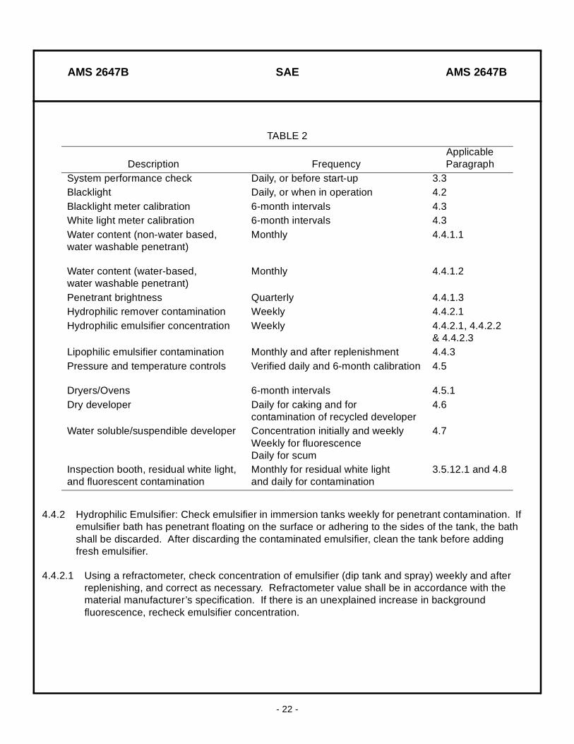
TABLE 2
Description FrequencyApplicableParagraph
System performance check Daily, or before start-up 3.3Blacklight Daily, or when in operation 4.2Blacklight meter calibration 6-month intervals 4.3White light meter calibration 6-month intervals 4.3Water content (non-water based, water washable penetrant)
Water content (water-based, water washable penetrant)
Monthly
Monthly
4.4.1.1
4.4.1.2
Penetrant brightness Quarterly 4.4.1.3Hydrophilic remover contamination Weekly 4.4.2.1Hydrophilic emulsifier concentration Weekly 4.4.2.1, 4.4.2.2
& 4.4.2.3Lipophilic emulsifier contamination Monthly and after replenishment 4.4.3Pressure and temperature controls
Dryers/Ovens
Verified daily and 6-month calibration
6-month intervals
4.5
4.5.1Dry developer Daily for caking and for
contamination of recycled developer4.6
Water soluble/suspendible developer Concentration initially and weeklyWeekly for fluorescenceDaily for scum
4.7
Inspection booth, residual white light, and fluorescent contamination
Monthly for residual white light and daily for contamination
3.5.12.1 and 4.8
AMS 2647B SAE AMS 2647B
- 23 -
4.4.2.2 For immersion application, the concentration of emulsifier shall be no higher than the manufacturer’s qualified (approved) concentration as specified in QPL 25135 or QPL-AMS-2644.
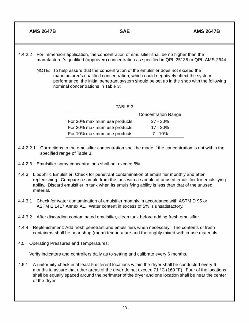
NOTE: To help assure that the concentration of the emulsifier does not exceed the manufacturer’s qualified concentration, which could negatively affect the system performance, the initial penetrant system should be set up in the shop with the following nominal concentrations in Table 3:
4.4.2.2.1 Corrections to the emulsifier concentration shall be made if the concentration is not within the specified range of Table 3.
4.4.2.3 Emulsifier spray concentrations shall not exceed 5%.
4.4.3 Lipophilic Emulsifier: Check for penetrant contamination of emulsifier monthly and after replenishing. Compare a sample from the tank with a sample of unused emulsifier for emulsifying ability. Discard emulsifier in tank when its emulsifying ability is less than that of the unused material.
4.4.3.1 Check for water contamination of emulsifier monthly in accordance with ASTM D 95 or ASTM E 1417 Annex A1. Water content in excess of 5% is unsatisfactory.
4.4.3.2 After discarding contaminated emulsifier, clean tank before adding fresh emulsifier.
4.4.4 Replenishment: Add fresh penetrant and emulsifiers when necessary. The contents of fresh containers shall be near shop (room) temperature and thoroughly mixed with in-use materials.
4.5 Operating Pressures and Temperatures:
Verify indicators and controllers daily as to setting and calibrate every 6 months.
4.5.1 A uniformity check in at least 5 different locations within the dryer shall be conducted every 6 months to assure that other areas of the dryer do not exceed 71 °C (160 °F). Four of the locations shall be equally spaced around the perimeter of the dryer and one location shall be near the center of the dryer.
TABLE 3
Concentration Range
For 30% maximum use products: 27 - 30%For 20% maximum use products: 17 - 20%For 10% maximum use products: 7 - 10%
AMS 2647B SAE AMS 2647B
- 24 -
4.6 Dry Developing Powders:
4.6.1 Check dry developer daily to ensure it is fluffy and not caked. Discard if it is caked (See 8.2.7).
4.6.2 Check recycled dry developer daily for contamination by forming a thin layer approximately 100 mm (4 inches) in diameter on a paper towel and examine under blacklight. Discard developer if ten or more fluorescent specks appear.
4.6.3 Check automated developing system daily to ensure it is working properly and guns are not clogged.
4.7 Water Soluble/Suspendible Developers:
4.7.1 Check concentration in dip tanks initially and at least weekly with a hydrometer. Specific gravity shall be in accordance with manufacturer’s specification.
4.7.2 Scan the surface of developer weekly with a blacklight for indications of fluorescence. Immerse a clean aluminum panel approximately 75 x 250 mm (3 x 10 inches) in the developer and remove for drying and inspection under blacklight for indications of fluorescence and surface wetting. Replace developer when fluorescence is detected.
4.7.3 Check developer daily for scum on the surface or inability to completely wet the surface of parts being inspected. Replace the developer if any of these conditions is evident.
4.7.3.1 If contaminated developer is discarded, ensure tank is cleaned before adding fresh developer.
4.8 Inspection Booth:
With curtains drawn, check residual white light in booth at least monthly using a white light meter (See 3.5.12.1). Confirm daily cleanliness of the work area and absence of fluorescent contamination, which may contaminate parts or degrade the inspection.
4.9 Material Storage:
Properly store and legibly identify all materials in accordance with the material manufacturer recommendations.
4.10 Material Check:
The designation and frequency of required material checks are specified in Table 2 (See 4.1).
6. ACKNOWLEDGMENT:
A vendor shall mention this specification number and its revision letter in all quotations and when acknowledging purchase orders.
AMS 2647B SAE AMS 2647B
- 25 -
7. REJECTIONS:
Parts not conforming to this specification, or to modifications authorized by purchaser, will be subject to rejection.
8. NOTES:
8.1 The change bar ( l ) located in the left margin is for the convenience of the user in locating areas where technical revisions, not editorial changes, have been made to the previous issue of this specification. An (R) symbol to the left of the document title indicates a complete revision of the specification.
8.2 Terms used in AMS are clarified in ARP1917 and as follows:
8.2.1 Angstrom: A unit of length formerly used to express wavelength of electromagnetic radiation. One angstrom equals 0.1 nanometer.
8.2.2 Background: The surface of the part upon which the indication is viewed. It may be either the natural surface of the test part or the developer coating on the surface.
8.2.3 Background Fluorescence: Fluorescent residues observed over the general surface of the test part. Local areas of background fluorescence are generally caused by improper penetrant removal or surface contamination. Such contamination, if present, can interfere with the visibility of defect indications.
8.2.4 Blacklight: Electromagnetic radiation in the near ultraviolet range of wavelength 3300 to 3900 Angstrom units (330 to 390 nm). See also, Ultraviolet Light 8.2.60.
8.2.5 Blacklight Filter: See Filter 8.2.33.
8.2.6 Blacklight Meter: A meter containing photo sensitive cells for reading of blacklight intensity in microwatts per square centimeter (µW/cm2).
8.2.7 Caked: A semi-solid condition of dry developer caused by moisture or other liquid contaminants.
8.2.8 Capillary Action: The tendency of certain liquids to travel, climb, or draw into tight crack-like interface areas due to such properties as surface tension, wetting, cohesion, and adhesion.
8.2.9 Cognizant Engineering Organization (CEO): The company, agency, or other authority responsible for the design or delivery, and the end use of the system or component for which liquid penetrant examination is required. This in addition to design personnel may include personnel from material and process engineering, stress analysis, NDT or quality groups, as appropriate.
8.2.10 Contact Time: The total time between application and removal of the penetrant or emulsifier or remover, or both.

AMS 2647B SAE AMS 2647B
- 26 -
8.2.11 Contaminants: Any material or material residue which interferes with entry of the penetrant into surface discontinuities. Also pertains to material left on the surface of the part because of improper cleaning and retained residual penetrant. Can also mean undesired materials in the penetrant, emulsifier, and remover, which affect their performance.
8.2.12 Dark Adaptation: The adjustment of the eyes, which commences when one passes from a bright to a darkened place.
8.2.13 Defect: Discontinuity, which exceeds specified acceptance criteria.
8.2.14 Degreasing: A cleaning method using solvents or cleaners employed to remove oil and grease from the surface of the part before the penetrant is applied.
8.2.15 Developer: A material that is applied to the test part surface after the excess penetrant has been removed and that is designed to enhance the penetrant bleedout to form indications. The developer may be a fine dry powder, or a suspension (in solvent or water) that dries leaving an absorbent film on the test part surface.
8.2.16 Developer, Dry: A dry, fine powder that is applied as a dust to the test part after the excess penetrant is removed and the surface dried.
8.2.17 Developer, Nonaqueous Wet (NAWD): A developer consisting of fine particles suspended in a volatile solvent which is applied by spraying onto the test part surface after the excess penetrant is removed and the surface dried.
8.2.18 Developer, Soluble: A material completely soluble in its carrier (usually water) which dries to an absorbent coating. It is applied to the part after removal of the excess penetrant and prior to drying.
8.2.19 Developing Time: The elapsed time between the application of dry developer or NAWD and the examination of the part for indications. Also the elapsed time between removal of the part from the dryer and the examination when using water-soluble developer.
8.2.20 Discontinuity: Any interruption in the normal physical structure or configuration of a part, such as cracks, laps, seams, inclusions, or porosity. A discontinuity may or may not be a relevant defect.
8.2.21 Drain Time: That portion of the contact or dwell time during which the excess penetrant, emulsifier, or remover drains off the test piece.
8.2.22 Drying Oven: A low temperature oven used for drying rinse water from the test part or to hasten drying of aqueous wet developer.
8.2.23 Drying Time: The time required for a rinsed or wet-developed part to dry.

AMS 2647B SAE AMS 2647B
- 27 -
8.2.24 Dwell Time: The total time that a penetrant, emulsifier, remover, or developer spends in contact with the component. For aqueous and nonaqueous developers, the dwell time starts after the developer is dry on the component.
8.2.25 Emulsifier: A liquid that interacts with an oily penetrant to make it water washable.
8.2.26 Emulsification Time: The total time that an emulsifier is permitted to combine with the penetrant prior to removal by water.
8.2.27 Engine Parts: Disassembled turbine or reciprocating engine parts or components.
8.2.28 Major Engine Rotor Component: A rotating part whose life is governed by low cycle fatigue limits or other mechanical property limits. (Examples: disks, shafts, spools, hubs, spacers, seals.)
8.2.29 Etching: A process for the controlled removal of surface material by chemical agents. May be used to remove smeared metal caused by intentional or adventitious cold working.
8.2.30 Evaluation: A process of determining the severity of the condition after a penetrant indication has been interpreted. Evaluation leads to determining whether the part is acceptable, salvageable, or rejectable.
8.2.31 False Indication: A penetrant indication that might be erroneously interpreted as a defect or discontinuity in the test part.
8.2.32 Family: The complete series of compatible materials from one manufacturer designed to perform a specific process of penetrant inspection.
8.2.33 Filter: Used in conjunction with a mercury vapor lamp to suppress visible and harmful short-wavelength ultraviolet radiation’s and to transmit near ultraviolet radiation.
8.2.34 Flaw: An imperfection in a part or material which may or may not be relevant to the function of the part.
8.2.35 Fluorescence: The emission of light (usually yellow-green) by fluorescent penetrant as the result of, and only during, irradiation by ultraviolet light.
8.2.36 Fluorescent Contamination: Contamination of parts or developer with fluorescent penetrant. Also, contamination of the inspection area.
8.2.37 Foot-candle: The illumination on a surface, 0.09 m2 (1 square foot) in area, on which is uniformly distributed a flux of 2 lm (lumen). It equals 10.8 lm/m2 or 0.09 lx.
8.2.38 Hydrophilic Emulsifier: A water soluble detergent concentrate used with the post emulsifiable penetrants.
AMS 2647B SAE AMS 2647B
- 28 -
8.2.39 Indication (Penetrant): The visible evidence of penetrant fluorescence indicating to the inspector that some sort of surface anomaly is present. Indications may be either false or valid, or may be relevant or nonrelevant.
8.2.40 Inspection: Visual examination of test parts, using blacklight, after completion of the penetrant processing steps.
8.2.41 Interpretation: The determination of the significance of the indications from the standpoint of whether they are relevant or nonrelevant.
8.2.42 Known Defect Test Standard: A test standard containing known defects used to perform system performance checks and classify penetrants.
8.2.43 Lipophilic Emulsifier: A ready to use oil base emulsifier which is miscible with penetrant. The resulting mixture of the two oils is easily emulsified under a water spray.
8.2.44 Micro (µ): A prefix that indicates one millionth (10-6).
8.2.45 µW/cm2: Microwatts per square centimeter. Units used in measurement of short wavelength energy.
8.2.46 Nonrelevant Indication: A penetrant indication that is not or cannot be associated with a discontinuity.
8.2.47 Part or Material Specifications: A specification provided by the OEM in the form of manuals, drawings or other documents that instruct the user in the maintenance and handling of specific parts or components.
8.2.48 Penetrant: A liquid capable of entering discontinuities or defects open to the surface and which is adapted to the inspection process by being highly visible in small traces.
8.2.49 Penetrant, Fluorescent: An inspection penetrant that is characterized by its ability to fluoresce when excited by blacklight.
8.2.50 Penetrant, Post Emulsifiable: A penetrant that requires the application of a separate emulsifier to render the surface penetrant water-washable.
8.2.51 Penetrant, Water-Washable: A penetrant with built-in emulsifier which makes it directly water-washable.
8.2.52 Post Inspection Cleaning: The removal of penetrant material residues and developer from the test part after the penetrant inspection process is completed.
8.2.53 Precleaning: The removal of surface contaminant from the test part so that it cannot interfere with the penetrant inspection process.
AMS 2647B SAE AMS 2647B
- 29 -
8.2.54 Prime Reliable Part (PRP): Disks, rotors, hubs shafts, major rotating seals and spacers, etc. which function within an engine. Failure of these parts may cause substantial damage and could potentially result in an uncontained failure and possible loss of an aircraft.
8.2.55 Refractometer: A device that measures the refractive index of a liquid. This value increases in proportion to the dissolved solids in the liquid, and hence has been used to measure hydrophilic remover concentration.
8.2.56 Relevant Indication: An indication caused by a discontinuity.
8.2.57 Rinse: The process of removing liquid penetrant inspection materials from the surface of the test part by means of washing with water. Also termed “wash”.
8.2.58 Sensitivity: The ability to produce various size discontinuities. The three categories of penetrant materials, i.e., medium, high, ultra high, as determined by known defect standards.
8.2.59 Specific Gravity: The ratio of the density of a substance (usually aqueous developer) to the density of water usually measured at 15.6 °C (60 °F).
8.2.60 Ultraviolet Light (UV): The term applied for radiation below the visible range. As used in fluorescent penetrant inspection between 3000 and 3900 Angstrom units (330 and 390 nm). See also, blacklight 8.2.4.
8.2.61 Viscosity: The state or degree of being viscous, i.e., the resistance of a fluid to flow, for example, through a restricted orifice.
8.2.62 Water Content: The percentage of water contamination of a sample of water washable penetrant or lipophilic emulsifier taken from the process tanks.
8.2.63 White Light Meter: A meter that will measure white light in foot-candles or lux.
8.3 Dimensions in SI units and the Celsius temperatures are primary; dimensions and properties in inch/pound units and the Fahrenheit temperatures are shown as the approximate equivalents of the primary units and are presented only for information.
8.3.1 Units without parentheses are primary due to normal usage.
8.4 Procurement documents should specify not less than:
AMS 2647B
PREPARED UNDER THE JURISDICTION OF AMS COMMITTEE “K”