application of layer-by-layer clustering to a generalised calorimeter chris ainsley university of...
Post on 19-Dec-2015
219 views
TRANSCRIPT
Application of layer-by-layer Application of layer-by-layer clustering to a generalised clustering to a generalised
calorimetercalorimeter
Chris Ainsley
University of Cambridge<[email protected]>
General CALICE meeting14-16 March 2005, NIU, De Kalb, IL, USA
Chris Ainsley<[email protected]>
General CALICE meeting 14-16 March 2005, NIU, De Kalb, IL, USA
2
Order of serviceOrder of service
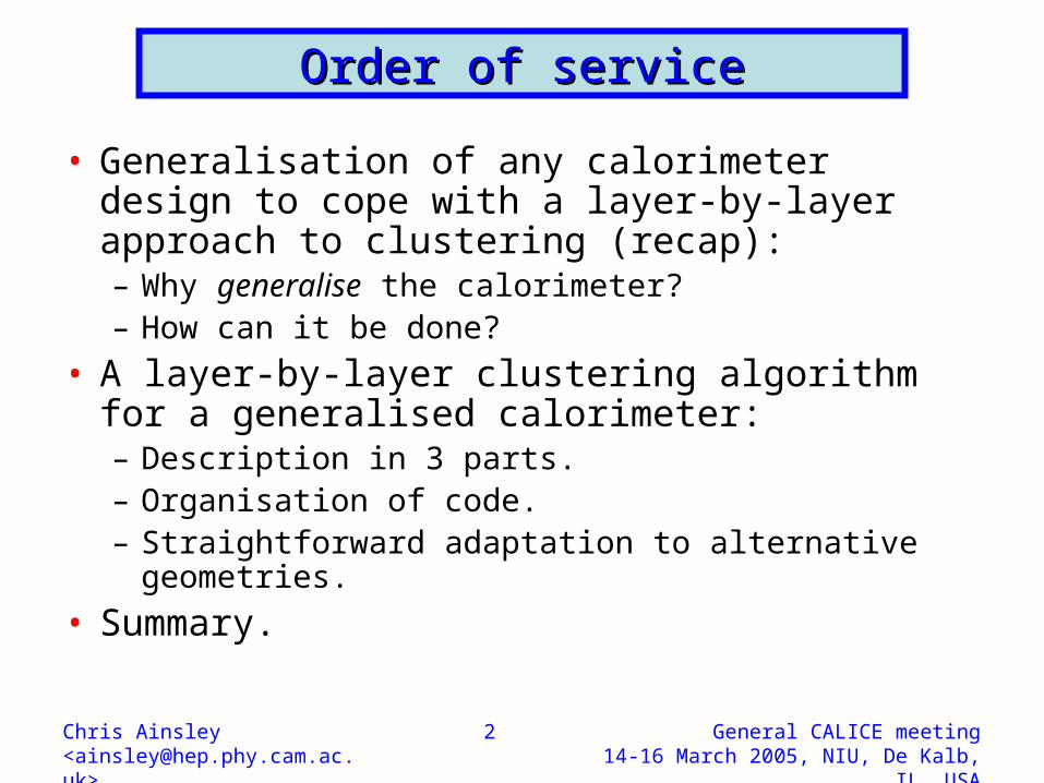
• Generalisation of any calorimeter design to cope with a layer-by-layer approach to clustering (recap):– Why generalise the calorimeter?– How can it be done?
• A layer-by-layer clustering algorithm for a generalised calorimeter:– Description in 3 parts.– Organisation of code.– Straightforward adaptation to alternative geometries.
• Summary.

Chris Ainsley<[email protected]>
General CALICE meeting 14-16 March 2005, NIU, De Kalb, IL, USA
3
Generalising the calorimeter (1)Generalising the calorimeter (1)
• Algorithms for calorimeter clustering exist, but tend to be tied to specific geometries.
• To compare relative merits of different detector designs, desirable to have an algorithm which requires minimal geometrical information can depend only upon hit coordinates/energies.
• Could propagate clusters outwards using hit radii from IP (i.e. place hits on artificial spherical layers)…naturally geometry independent, but does not reflect physical detector layout → calorimeter will not be spherical!
• Moreover, space will most likely be sampled in planes of layers would like to preserve the natural layer-indexing in propagating clusters outwards…
• …however, layers have different orientations in the barrel and the endcaps, as do different barrel staves complications in ranking hits by layer index.
• To make use of layer indexing, need to address these in a geometry-independent way.

Chris Ainsley<[email protected]>
General CALICE meeting 14-16 March 2005, NIU, De Kalb, IL, USA
4
Generalising the calorimeter (2)Generalising the calorimeter (2)
• Layer index changes discontinuously at• barrel/endcap boundary.• On crossing, jumps from l to 1 (first• Ecal layer).
• Define a “pseudolayer” index based on • projected intersections of physical layers. • Index varies smoothly across boundary.• Pseudolayer index = layer index, except• in overlap region.

Chris Ainsley<[email protected]>
General CALICE meeting 14-16 March 2005, NIU, De Kalb, IL, USA
5
Generalising the calorimeter (3)Generalising the calorimeter (3)
• Layer index changes discontinuously at• boundary between overlapping barrel • staves.• On crossing, jumps from l to 1 (first• Ecal layer.
• Again, define “pseudolayer” index from• projected intersections of physical layers.• Again, index varies smoothly across• boundary.• Again, pseudolayer index = layer index, • except in overlap region.
Chris Ainsley<[email protected]>
General CALICE meeting 14-16 March 2005, NIU, De Kalb, IL, USA
6
Generalising the calorimeter (4)Generalising the calorimeter (4)
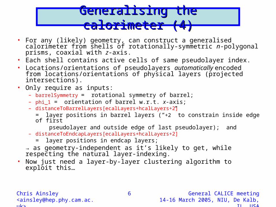
• For any (likely) geometry, can construct a generalised calorimeter from shells of rotationally-symmetric n-polygonal prisms, coaxial with z-axis.
• Each shell contains active cells of same pseudolayer index.• Locations/orientations of pseudolayers automatically encoded from
locations/orientations of physical layers (projected intersections).• Only require as inputs:
– barrelSymmetry = rotational symmetry of barrel;– phi_1 = orientation of barrel w.r.t. x-axis; – distanceToBarrelLayers[ecalLayers+hcalLayers+2] – = layer positions in barrel layers (“+2” to constrain inside edge of first– pseudolayer and outside edge of last pseudolayer); and– distanceToEndcapLayers[ecalLayers+hcalLayers+2] – = layer positions in endcap layers;
• → as geometry-independent as it’s likely to get, while respecting the natural layer-indexing.
• Now just need a layer-by-layer clustering algorithm to exploit this…

Chris Ainsley<[email protected]>
General CALICE meeting 14-16 March 2005, NIU, De Kalb, IL, USA
7
Clustering: stage 1Clustering: stage 1
• Form coarse clusters by tracking closely-related hits (> mipThreshold) layer-by-layer through calorimeter:
– for a candidate hit in a given layer, l, minimize the distance, d, w.r.t all (already clustered) hits in layer l1;
– if d < distMax for minimum d, assign candidate hit to same cluster as hit in layer l1 which yields minimum;
– if not, repeat with all hits in layer l2, then, if necessary, layer l3, etc., right through to layer llayersToTrackBack;
– after iterating over all hits in layer l, seed new clusters with those still unassigned, grouping those within proxSeedMax of highest weighted remaining hit into same seed;
– assign a direction cosine to each layer l hit:• if in Ecal, calculate weighted centre of each
cluster’s hits in layer l (weight by energy (analogue) or density (digital)); assign a direction cosine to each hit along the line joining its cluster’s centre in the seed layer (or (0,0,0) if it’s a seed) to its cluster’s centre in layer l;
• if in Hcal, assign a direction cosine to each hit along the line from the hit to which each is linked (or (0,0,0) if it’s a seed) to the hit itself;
– iterate outwards through layers.

Chris Ainsley<[email protected]>
General CALICE meeting 14-16 March 2005, NIU, De Kalb, IL, USA
8
Clustering: stage 2Clustering: stage 2
• Try to merge backward-spiralling track-like cluster-fragments with the forward propagating clusters to which they belong:– for each hit in the terminating layer,
l, of a candidate cluster fragment, calculate the distance, p, to each hit in nearby clusters in the same layer, and the angle, , between their direction cosines;
– loop over all pairs of hits;– if, for any pair, both:
• p < proxMergeMax and • cos < cosGammaMax
are satisfied, merge clusters together into one;
– iterate over clusters.

Chris Ainsley<[email protected]>
General CALICE meeting 14-16 March 2005, NIU, De Kalb, IL, USA
9
Clustering: stage 3Clustering: stage 3
• Try to merge low multiplicity cluster “halos” (hit multiplicity < clusterSizeMin ) which just fail the stage 1 cluster-continuation cuts:
– for the highest weighted candidate hit in the seed layer, l, of a low multiplicity cluster, minimize the angle, , w.r.t all hits in layer l1;
– if tan < tanBetaMax for minimum , merge the clusters containing the repsective hits into one;
– if not, repeat with all hits in layer l2, then, if necessary, layer l3, etc., right through to layer llayersToTrackBack;
– if still not, repeat above steps with the next highest weighted candidate hit of the low multiplicity cluster in the seed layer, etc. .
– if still not, merge the low multiplicity cluster into the nearest cluster in the same layer, provided the two clusters contain hits separated by s < proxMergeMax;
– iterate over clusters.

Chris Ainsley<[email protected]>
General CALICE meeting 14-16 March 2005, NIU, De Kalb, IL, USA
10
5 GeV 5 GeV ++ event: 3 stages of event: 3 stages of clusteringclustering
Clusters: stage 1
• One backward-spiralling track • and several halo clusters• surround principal cluster.
Clusters: stage 2 Clusters: stage 3
• Backward-spiralling track• merged with principal cluster.
• Halo clusters merged with• principal cluster.

Chris Ainsley<[email protected]>
General CALICE meeting 14-16 March 2005, NIU, De Kalb, IL, USA
11
91 GeV Z → u,d,s jets event91 GeV Z → u,d,s jets event
Reconstructed clusters True particle clusters

Chris Ainsley<[email protected]>
General CALICE meeting 14-16 March 2005, NIU, De Kalb, IL, USA
12
How it’s coded in LCIO with How it’s coded in LCIO with MARLIN (1)MARLIN (1)
• Code structured as a series of “processors”, (requiring compilation) together with a steering file: my.steer (read at run-time).
• Processors to do the reconstruction:– CalorimeterConfig.cc
→ (re)sets calorimeter layer positions;– HitToCell.cc
→ merges same-cell hits (MC);– CellToStore.cc
→ stores cells above energy threshold (MC); – StoreToStoreOrdered.cc
→ ranks stored cells by weight in each pseudolayer (in preparation for clustering);
– StoreOrderedToCluster1.cc→ does the coarse cluster reconstruction;
– Cluster1ToCluster2.cc→ attempts matching of backward-spiralling track-like cluster fragments onto forward-propagating parent clusters;
– Cluster2ToCluster3.cc→ attempts to reunite low multiplicity “halo’ cluster fragments with parent clusters.
• Additional processor to access MC truth:– StoreOrderedToTrueCluster.cc
→ forms the true clusters.• To apply algorithm to alternative detector
designs, just need to modify parameters in CalorimeterConfig.cc and my.steer, then play → quite straightforward.
• Reconstruction code itself requires no modification.
• Recompilation necessary only for CalorimeterConfig.cc, and then only if layer positions change.
• All other detector parameters, and all clustering cuts, set at run-time in my.steer.
• Let’s see how …

Chris Ainsley<[email protected]>
General CALICE meeting 14-16 March 2005, NIU, De Kalb, IL, USA
13
How it’s coded in LCIO with How it’s coded in LCIO with MARLIN (2)MARLIN (2)
• Example (section of) code from my.steer (e.g. based on CALICE design; Si/W Ecal, Fe/RPC Hcal):
ProcessorType CalorimeterConfigdetectorTypefull # detector type ("full" or "prototype")ecalLayers 40 # number of Ecal layershcalLayers 40 # number of Hcal layersbarrelSymmetry 8 # degree of rotational symmetry of barrelphi_1 90.0 # phi offset of first barrel stave w.r.t. x-axis (in deg)
ProcessorType CellToStoremode a/d # analogue mode ("a") or digital mode ("d") for Ecal/Hcal
# ("a/a", "a/d", "d/a" or "d/d") ecalMip 0.000150 # Ecal Mip energy (in GeV)hcalMip 0.0000004 # Hcal Mip energy (in GeV)ecalMipThreshold 0.33333333 # Ecal Mip threshold (in Mip units)hcalMipThreshold 0.33333333 # Hcal Mip threshold (in Mip units)
ProcessorType StoreOrderedToCluster1layersToTrackBack 80 # number of layers to track back for cluster continuationdistMax_ecal20.0 # Ecal distance cut for cluster continuation (in mm)distMax_hcal30.0 # Hcal distance cut for cluster continuation (in mm)proxSeedMax_ecal 20.0 # Ecal seed radius cut (in mm)proxSeedMax_hcal 20.0 # Hcal seed radius cut (in mm)
ProcessorType Cluster1ToCluster2proxMergeMax_ecal 20.0 # Ecal proximity cut for cluster merging (in mm)proxMergeMax_hcal 20.0 # Hcal proximity cut for cluster merging (in mm)cosGammaMax 0.25 # angular cut for cluster merging
ProcessorType Cluster2ToCluster3clusterSizeMin 10 # minimum cluster size to avert potential cluster merginglayersToTrackBack 80 # number of layers to track back for cluster mergingtanBetaMax 6.0 # angular cut for cluster mergingproxSeedMax_ecal 400.0 # Ecal proximity cut for cluster merging (in mm)proxSeedMax_hcal 400.0 # Hcal proximity cut for cluster merging (in mm)

Chris Ainsley<[email protected]>
General CALICE meeting 14-16 March 2005, NIU, De Kalb, IL, USA
14
How it’s coded in LCIO with How it’s coded in LCIO with MARLIN (3)MARLIN (3)
• Example (section of) code from CalorimeterConfig.cc (e.g. based on CALICE design):
// Create collections for the barrel and endcap layer positions LCCollectionVec* distanceToBarrelLayersVec = new LCCollectionVec(LCIO::LCFLOATVEC);
LCCollectionVec* distanceToEndcapLayersVec = new LCCollectionVec(LCIO::LCFLOATVEC);
// Fill the collections with their positions (in mm)for(int l=0; l<=ecalLayers+hcalLayers+1; l++) { LCFloatVec* distanceToBarrelLayers = new LCFloatVec; LCFloatVec* distanceToEndcapLayers = new LCFloatVec; if(detectorType=="full") { // full detector if(l<=30) { // first 30 Ecal layers at a pitch of 3.9 mm (+ layer 0) edit distanceToBarrelLayers->push_back(1698.85+(3.9*l)); edit distanceToEndcapLayers->push_back(2831.10+(3.9*l)); edit } edit else if(l>30 && l<=ecalLayers) { // last 10 Ecal layers at a pitch of 6.7 mm edit distanceToBarrelLayers->push_back(1815.85+(6.7*(l-30))); edit distanceToEndcapLayers->push_back(2948.10+(6.7*(l-30))); edit } edit else { // 40 Hcal layers at a pitch of 24.5 mm (+ layer 81) edit distanceToBarrelLayers->push_back(1931.25+(24.5*(l-41))); edit distanceToEndcapLayers->push_back(3039.25+(24.5*(l-41))); edit } edit } else if(detectorType=="prototype") { …some more code… } // prototype detector distanceToBarrelLayersVec->push_back(distanceToBarrelLayers); distanceToEndcapLayersVec->push_back(distanceToEndcapLayers);}
// And save the collectionsevt->addCollection(distanceToBarrelLayersVec, "distance_barrellayers");evt->addCollection(distanceToEndcapLayersVec, "distance_endcaplayers");

Chris Ainsley<[email protected]>
General CALICE meeting 14-16 March 2005, NIU, De Kalb, IL, USA
15
Summary & outlookSummary & outlook
• Developed a scheme to enable a (pseudo)layer-by-(pseudo)layer clustering procedure to be applied to alternative calorimeter geometries without having to recode the algorithm itself.
• Straightforwardly applicable to any (likely) detector design comprising an n-fold rotationally symmetric barrel closed by endcaps → just need to specify n, barrel orientation, and layer positions.
• Proposed such an algorithm that utilizes the high granularity of the calorimeter cells to “track” clusters (pseudo)layer-by-(pseudo)layer outwards (and retrospectively deal with backward-spiralling off-shoots).
• Coded in C++; LCIO (v1.3) fully compliant → outputs cluster objects with pointers back to component hits and attributes.
• Code is modularised thanks to MARLIN input parameters (set at run-time) kept distinct from reconstruction (pre-compiled).
• Will be publicly releasable pretty soon.

Chris Ainsley<[email protected]>
General CALICE meeting 14-16 March 2005, NIU, De Kalb, IL, USA
16
The endThe end
That’s all folks…

Chris Ainsley<[email protected]>
General CALICE meeting 14-16 March 2005, NIU, De Kalb, IL, USA
17
How the generalised detector How the generalised detector shapes upshapes up
Transverse section Longitudinal section
• Solid blue lines aligned along real, physical, sensitive layers.• Dot-dashed magenta lines bound shell containing hits with same pseudolayer index, l.• Pseudostaves automatically encoded by specifying n, 1 and Rl and Zl
( l).

Chris Ainsley<[email protected]>
General CALICE meeting 14-16 March 2005, NIU, De Kalb, IL, USA
18
Cluster-tracking between Cluster-tracking between pseudolayerspseudolayers
From the pseudobarrel From the pseudoendcap

Chris Ainsley<[email protected]>
General CALICE meeting 14-16 March 2005, NIU, De Kalb, IL, USA
19
5 GeV 5 GeV ++ event at 3 cm event at 3 cm separationseparation
Reconstructed clusters True particle clusters
• Energy calibrated (CALICE D09 detector) according to:• E = [(EEcal; 1-30 + 3EEcal; 31-40)/Emip + 20NHcal] GeV.• Hits map mostly black black (+) and red red () between reconstructed and true clusters.• Fraction of event energy in 1:1 correspondence = 55.2 + 42.6 = 98 %.

Chris Ainsley<[email protected]>
General CALICE meeting 14-16 March 2005, NIU, De Kalb, IL, USA
20
5 GeV 5 GeV ++ event at 5 cm event at 5 cm separationseparation
Reconstructed clusters True particle clusters
• Energy calibrated (CALICE D09 detector) according to:• E = [(EEcal; 1-30 + 3EEcal; 31-40)/Emip + 20NHcal] GeV.• Hits map mostly black black () and red red (+) between reconstructed and true clusters.• Fraction of event energy in 1:1 correspondence = 57.0 + 37.5 = 94 %.

Chris Ainsley<[email protected]>
General CALICE meeting 14-16 March 2005, NIU, De Kalb, IL, USA
21
• Energy calibrated (CALICE D09 detector) according to:• E = [(EEcal; 1-30 + 3EEcal; 31-40)/Emip + 20NHcal] GeV.• Hits map mostly black black (+) and red red (n) between reconstructed and true clusters.• Fraction of event energy in 1:1 correspondence = 46.3 + 40.1 = 86 %.
5 GeV 5 GeV ++n event at 5 cm n event at 5 cm separationseparation
Reconstructed clusters True particle clusters

Chris Ainsley<[email protected]>
General CALICE meeting 14-16 March 2005, NIU, De Kalb, IL, USA
22
5 GeV two-particle quality vs 5 GeV two-particle quality vs separationseparation
• Goal: to distinguish charged clusters from neutral clusters in calorimeters e.g. + / +n.
• Propose a figure of merit:
Quality = fraction of event energy that maps in a 1:1 ratio between reconstructed and true clusters.
• Quality improves with separation (naturally).
+ separation at 5 GeV seems to be pretty good; +n is somewhat tougher (n showers typically have relatively ill-defined shapes).

Chris Ainsley<[email protected]>
General CALICE meeting 14-16 March 2005, NIU, De Kalb, IL, USA
23
Calibration of Calibration of ++, , and n and n
++ nn
• Energy calibrated (CALICE D09 detector) according to:• E = [(EEcal; 1-30 + 3EEcal; 31-40)/Emip + 20NHcal] GeV.