atlantic mills 3,000,000 gallon composite elevated …
TRANSCRIPT

SPECIFICATION AND CONTRACT DOCUMENTS
FOR THE
ATLANTIC MILLS
3,000,000 GALLON COMPOSITE ELEVATED TANK
(DIVISION I & II)
FOR THE
MACON WATER AUTHORITY 790 Second Street Macon, GA 31202
(478) 464-5620 Fax (478) 741-1239
JANUARY, 2020
Funding Source: Macon Water Authority (Bond Funds) 100%
PREPARED BY:
1 01/2020
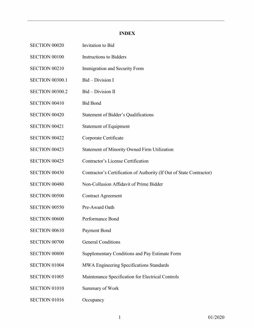
INDEX SECTION 00020 Invitation to Bid SECTION 00100 Instructions to Bidders SECTION 00210 Immigration and Security Form SECTION 00300.1 Bid – Division I SECTION 00300.2 Bid – Division II SECTION 00410 Bid Bond SECTION 00420 Statement of Bidder’s Qualifications SECTION 00421 Statement of Equipment SECTION 00422 Corporate Certificate SECTION 00423 Statement of Minority Owned Firm Utilization SECTION 00425 Contractor’s License Certification SECTION 00430 Contractor’s Certification of Authority (If Out of State Contractor) SECTION 00480 Non-Collusion Affidavit of Prime Bidder SECTION 00500 Contract Agreement SECTION 00550 Pre-Award Oath SECTION 00600 Performance Bond SECTION 00610 Payment Bond SECTION 00700 General Conditions SECTION 00800 Supplementary Conditions and Pay Estimate Form SECTION 01004 MWA Engineering Specifications Standards SECTION 01005 Maintenance Specification for Electrical Controls SECTION 01010 Summary of Work SECTION 01016 Occupancy

2 01/2020
SECTION 01025 Measurement & Payment SECTION 01055 Construction Staking SECTION 01060 Regulatory Requirements SECTION 01091 Codes and Standards SECTION 01200 Project Meetings SECTION 01310 Construction Schedules SECTION 01320 Construction Video and Photographs SECTION 01340 Shop Drawings, Product Data and Samples SECTION 01410 Testing Laboratory Services SECTION 01510 Temporary Facilities SECTION 01540 Job Site Security SECTION 01562 Dust Control SECTION 01610 Transportation and Handling SECTION 01611 Storage and Protection SECTION 01630 Substitutions and Options SECTION 01710 Cleaning SECTION 01720 Record Documents SECTION 01740 Warranties and Bonds SECTION 02205 Construction Erosion Control for Roadway Projects SECTION 02209 Erosion Control SECTION 02220 Demolition SECTION 02225 Excavation, Trenching & Backfill for Utility Systems SECTION 02230 Site Clearing SECTION 02315 Rock Removal (Unclassified) SECTION 02316 Rock Removal (Classified)

3 01/2020
SECTION 02370 Soil Erosion Control SECTION 02401 Minor Drainage Structures SECTION 02452 Black PVC Fencing SECTION 02501 Subbase and Base Course SECTION 02502 Hot Mix Recycled Asphalt Concrete SECTION 02511 Concrete Pavement and Miscellaneous Concrete SECTION 02709 Water Distribution System SECTION 02920 Grassing SECTION 03300 Cast – In – Place Concrete SECTION 03600 Non-Shrink Grout SECTION 09902 Coatings and Finishes SECTION 10400 Identifying Devices SECTION 13394 SCADA System and Instrumentation SECTION 15294 Composite Elevated Water Storage Tank SECTION 15320 Tank Mixing System – Reservoir Hydrodynamic Mixing System SECTION 16010 Basic Electrical Requirements SECTION 16111 Conduit SECTION 16123 Building Wire and Cable SECTION 16130 Boxes SECTION 16141 Wiring Devices SECTION 16160 Terminal Blocks and Enclosures SECTION 16170 Grounding and Bonding SECTION 16180 Equipment Wiring Systems SECTION 16190 Supporting Devices

4 01/2020
SECTION 16195 Electrical Identification SECTION 16420 Electrical Services SECTION 16470 Panelboards SECTION 16510 Luminaries SECTION 16670 Lighting Protection for Structures SECTION 16902 Electrical Controls and Relays SECTION 16914 Gate Operator SECTION 16994 SCADA SECTION 16999 Field Acceptance Tests APPENDIX Preliminary Subsurface Exploration and Geotechnical Engineering Evaluation 3 MG Elevated Storage Tank, Macon, Georgia GEC Project No. 180671.210 Dated: September 11, 2018 Seismic Design Recommendations 3 MG Elevated Storage Tank, Macon, Georgia GEC Project No. HN180671.21 Dated: January 3, 2020 PERMITS FAA Determination of No Hazard to Air Navigation EPD Drinking Water Permitting & Engineering Program EPD General NPDES Permit No. GAR 100002

Macon Water Authority
1 01/2020
SECTION 00020 INVITATION TO BID
THE MACON WATER AUTHORITY Sealed Bids for furnishing all materials, labor, tools, equipment and appurtenances necessary for the installation of Atlantic Mills 3,000,000 Gallon Composite Elevated Tank, (the “Project”) will be received by the Macon-Bibb, Georgia (“Owner”), by and through the Owner’s agent, the Macon Water Authority, at the Macon Water Authority, 537 Hemlock Street, Conference Room, Macon, Georgia 31202 until 2:00 PM, local time, Tuesday, April 7, 2020, and then at said office publicly opened and read aloud. All bidders must attend a mandatory pre-bid meeting at the same location at 2:00 PM on Tuesday, March 24, 2020. All bid questions must be submitted to the Engineer by 2:00 PM on Tuesday, March 31, 2020. Division I -- Atlantic Mills Composite Tank The Project consists of erosion control items, tank construction items, site construction civil items, and miscellaneous items required to construct a 3,000,000 gallon composite elevated water storage tank, including electrical, coatings & finishes, SCADA, potable water site piping, landscaping, and all appurtenances. Division II – Water System Improvements – Atlantic Mills Tank Connection to System A future Project known as Division II is not advertised for bid. The future Division II Project will consist of extending water main(s) to other connections within the existing water system. The Project will be awarded in one Contract. Fifty-one percent (51%) of the Work under the Contract Documents must be self-performed by the General Contractor. The Project will be awarded by base bid plus selected alternates on a lump sum, fixed price basis for the performance and completion of all Work required by the Contract Documents. The Contract Documents include, but may not be limited to, the Instructions to Bidders, the Contract Agreement, the General Conditions, the Drawings, the Specifications and the forms of Bid Bond (if applicable), Performance Bond (if applicable), and Payment Bond (if applicable). These and any other Contract Documents may be examined at the following location:
Engineering Division Macon Water Authority
537 Hemlock Street Macon, GA 31202-0108
The Project advertised for bid is Division I, which is the tank project and associated site piping.
Division II is not advertised for bid at this time.

00020-2 Invitation to Bid
2 01/2020
Copies of Contract Documents may be obtained at the office of:
Hofstadter and Associates, Inc. 4571 Arkwright Road
Macon, GA 31210 478-757-1169 (office) / 478-471-1646 (fax)
upon payment of $150.00 per hard copy set of plans and specifications and $75.00 per digital set (.pdf format), non-refundable. A street address must be provided to ensure prompt delivery. No partial sets of bidding documents shall be issued. If the bid amount exceeds $25,000, the Bid must be accompanied by a Bid Bond in the amount of 10% of the Bid, prepared on the form of Bid Bond that is part of the Contract Documents, duly executed by the Bidder as principal and having as surety thereon a surety company licensed to do business in the State of Georgia and listed in the latest issue of U.S. Treasury Circular 570. Bidders must comply with the Minority Participation Requirements specified in the Instructions to Bidders. The Bidder shall affix to the outside of its Bid envelope the Bidder’s Georgia Utility Contractor License Number. A license number of a Utility Manager or a subcontractor is insufficient, and any Bid that fails to affix to the outside of its Bid envelope the Bidder’s Georgia Utility Contractor License Number may be rejected. The successful Bidder for this Project shall be required to furnish a Performance Bond and Payment Bond, satisfactory to the Owner and the Agent, each in the amount of 100 % of the Contract Price, if the Contract Price will exceed $25,000. Employment of Local Businesses and Contractors: It is the desire of the Owner that local businesses, including minorities and disadvantaged subcontractors, be given the opportunity to participate on the various parts of the Work. The Owner’s encouragement of participation of minority and locally owned businesses and contractors is not intended to restrict or limit competitive bidding or to increase the cost of the Work. The Owner supports a healthy, free market system that seeks to include responsible local businesses and provide ample opportunities for local business growth and development. The Owner reserves the right to reject any or all Bids. The Owner reserves the right to waive informalities and technicalities.
The Macon Water Authority R.A. “Tony” Rojas Executive Director
END OF SECTION

Macon Water Authority, Owner
1 06/2015
SECTION 00100 INSTRUCTIONS TO BIDDERS
1.01 CONTRACT DOCUMENTS A. The Bidder's attention is called to the definition of the Contract Documents contained
in Article 41 of the General Conditions. B. The Contract Documents shall define and describe the complete Work to which they
relate. 1.02 DEFINITIONS The Bidder's attention is called to the definitions set forth in Article 41 of the General
Conditions. 1.03 PREPARATION AND EXECUTION OF BID A. Each Bid must be prepared to represent that it is based solely upon the materials and
equipment specified in the Contract Documents. B. Each Bid must be submitted on the Bid forms which are a part of the Contract
Documents. All blank spaces for Bid prices, both words and figures, must be filled in, in ink. In case of discrepancy, the amount shown in words will govern. All required enclosed certifications must be fully completed and executed when submitted.
C. In case of discrepancies between the figures shown in the unit prices and the totals, the
unit prices shall apply and the totals shall be corrected to agree with the unit prices. In case of discrepancies between written amounts and figures, written amounts shall take precedence over figures and the sum of all Bid extensions (of unit prices) plus lump sum items shall take precedence over BID TOTAL.
D. Each Bid must be submitted in a sealed envelope, addressed to the Macon Water
Authority (the “Owner”). Each sealed envelope containing a Bid must be plainly marked on the outside as, "Division I -- Atlantic Mills 3,000,000 Gallon Composite Elevated Tank”.
E. The Bidder shall provide on the outside of the sealed envelope the following
information: 1. Bidder's Name;
2. Bidder's Georgia Utility Contractor License Number; and, 3. The words, “SEALED BID”.
F. Any Bid submitted which does not contain the above information on the outside of the
sealed envelope will not be opened and will be returned to the Bidder.

00100-2 Instructions to Bidders
2 06/2015
G. If forwarded by mail, the sealed envelope containing the Bid must be enclosed in another envelope addressed as follows:
THE MACON WATER AUTHORITY Attn: Mr. Monte Tolleson 537 Hemlock Street Post Office Box 108 Macon, Georgia 31202-0108 H. Any and all Bids not meeting the aforementioned criteria for Bid submittal, may be
declared non-responsive, and subsequently returned to the Bidder unopened. I. The Contractor, in signing a Bid on the whole or any portion of the Project, shall
conform to the following requirements: 1. Bids which are not signed by individuals making them shall have attached thereto
a power of attorney evidencing authority to sign the Bid in the name of the person for whom it is signed.
2. Bids which are signed for a partnership shall be signed by all of the partners or by
an attorney-in-fact. If a Bid is signed by an attorney-in-fact, there should be attached to the Bid a power of attorney executed by the partners evidencing authority to sign the Bid.
3. Bids which are signed for a corporation shall have the correct, legal corporate
name thereof, as reflected in the records of the Georgia Secretary of State, and the signature of the president or other authorized officer of the corporation manually written below the corporate name following the wording "By ". The corporate seal shall be affixed to the Bid.
4. The Bidder shall complete, execute and submit the following documents, which
are a part of the Contract Documents: a. The Bid; b. The Bid Bond; c. Statement of Bidder's Qualifications; d. Statement of Equipment; e. Corporate Certificate, if the Bidder is a corporation; f. Statement of Minority-Owned Firm Utilization;
g. Contractor's License Certification; h. Photocopy of State of Georgia Utility Contractor’s License; i. Photocopy of Certificate of Authority from Georgia Secretary of State’s
Office to do work in Georgia (if out of state contractor); and, j. Non-Collusion Affidavit of Prime Bidder

00100-3 Instructions to Bidders
3 06/2015
1.04 METHOD OF BIDDING The unit or lump sum price for each of the several items in the Bid of each Bidder shall
include its pro rata share of overhead and profit so that the sum of the products, obtained by multiplying the quantity shown for each item by the unit price, represents the total Bid. Any Bid not conforming to this requirement may be rejected. Additionally, unbalanced Bids will be subject to rejection. Conditional Bids shall not be accepted. The special attention of all Bidders is called to this provision, for should conditions make it necessary to revise the quantities, no limit will be fixed for such increased or decreased quantities nor extra compensation allowed.
1.05 ADDENDA AND INTERPRETATIONS A. No interpretation of the meaning of the Drawings, Specifications or other pre-bid
documents or Contract Documents shall be made to any Bidder orally. B. Any and all such interpretations and any supplemental instructions will be in the form
of written Addenda to the Contract Documents which, if issued, will be mailed, shipped or faxed to all prospective Bidders (at the respective addresses furnished) at least three (3) business days prior to the date fixed for the opening of Bids.
C. Failure of Bidders to receive or acknowledge any Addendum shall not relieve them of
any obligation under the Bid. All Addenda shall become part of the Contract Documents.
1.06 BID MODIFICATIONS Bidders may modify their Bid by facsimile communication at any time prior to the
scheduled closing time for receipt of Bids, provided such facsimile communication is received by the Owner prior to the closing time, and provided further, the Owner is satisfied that a written confirmation of the facsimile modification over the signature of the Bidder was mailed prior to the closing time. The facsimile communication should not reveal the Bid price but should provide the addition or subtraction or other modification so that the final prices or terms will not be known by the Owner or the Owner until the sealed Bid is opened. If written confirmation is not received within two business days from the closing time, no consideration will be given to the facsimile modification.
1.07 BID SECURITY
A. Each Bid exceeding $25,000 must be accompanied by a Bid Bond, prepared on the form of Bid Bond included herein, duly executed by the Bidder as principal and having as surety thereon a surety company authorized to do business in the State of Georgia and listed in the latest issue of U.S. Treasury Circular 570, in the amount of ten (10%) percent of the Bid. Attorneys-in-fact who sign Bonds must file with each Bond a currently dated copy of their power of attorney.

00100-4 Instructions to Bidders
4 06/2015
B. Except as provided by Georgia law, if for any reason whatsoever the successful Bidder
withdraws from the competition after opening of the Bids, or if Bidder refuses to execute and deliver the Contract and Bonds required in Article 2 of the General Conditions, the provisions of the Bid Bond may be enforced.
C. Except as provided by Georgia law, a Bid may not be revoked or withdrawn until sixty
(60) days after the time set for opening the Bids. Upon expiration of this time period, the Bid will cease to be valid, unless the Bidder provides written notice to the Owner prior to the scheduled expiration date that the Bid will be extended for a time period specified by the Owner.
1.08 RECEIPT AND OPENING OF BIDS The Owner may consider a technicality and informality any Bid not prepared and
submitted in strict accordance with the provisions hereof and may waive any technicality and informality or reject any and all Bids. Any Bid may be withdrawn prior to the above scheduled time for the opening of Bids or authorized postponement thereof. Any Bid received after the time and date specified shall not be opened.
1.09 CONDITIONS OF THE PROJECT A. Each Bidder must be informed fully of the conditions relating to the construction of the
Project and the employment of labor thereon. Failure to do so will not relieve a successful Bidder of the obligation to furnish all material and labor necessary to carry out the provisions of the Contract Documents. Insofar as possible, the Contractor, in carrying out the Work, must employ such methods or means as will not cause any interruption of or interference with the work of any other contractor.
B. The Bidder is advised to examine the location of the Project and to be informed fully as
to its conditions; access requirements, the conformation of the ground; the character, quality and quantity of the products needed preliminary to and during the prosecution of the work; the general and local conditions and all other matters which can in any way affect the work to be done under the Contract Documents. Failure to examine the site will not relieve the successful Bidder of an obligation to furnish all products and labor necessary to carry out the provisions of the Contract Documents.
C. The Bidder shall notify the Owner of the date and time Bidder proposes to examine the
location of the Project. The Bidder shall confine examination to the specific areas designated for the proposed construction, including easements and public right-of-ways. If, due to some unforeseen reason, the proceedings for obtaining the proposed construction site (including easements), have not been completed, the Bidder may enter the site only with the express consent of the property owner. The Bidder is solely responsible for any damages caused by examination of the site.
D. All anticipated federal, state and local permits required for the Project have been
obtained.

00100-5 Instructions to Bidders
5 06/2015
E. All rights of way and easements anticipated for the Project have been obtained. 1.10 EQUAL EMPLOYMENT OPPORTUNITY
A. During the performance of the Contract, the Bidder agrees as follows: 1. The Bidder shall not discriminate against any employee, or applicant for
employment, because of race, religion, color, sex, or national origin. As used herein, the words "shall not discriminate" shall mean and include, without limitation, recruiting, compensation, rates of pay, selection for training including apprenticeship, promotion, upgrading, demotion, downgrading, transfer, lay-off and termination.
2. The Bidder shall in all solicitation or advertisement for employees, placed by or
on behalf of the Bidder state that all qualified applicants will receive consideration for employment without regard to race, religion, color, sex or national origin.
3. The Bidder shall send to each labor union or representative of the workers, with
which the Contractor has a collective bargaining agreement or other contract or understanding, a notice advising the labor union or worker's representative of the Bidder's commitments under the Equal Employment Opportunity Program of the Owner and shall post copies of the notice in conspicuous places available to employees and applicants for employment.
4. The Bidder and his subcontractors, if any, shall file compliance reports at
reasonable times and intervals with the Owner in the form and to the extent prescribed by the Owner. Compliance reports filed at such times as directed shall contain information as to the employment practices, policies, programs and statistics of the Bidder and its subcontractors.
5. The Bidder shall demonstrate by the documentation required in Paragraph C.
below, that a "Good Faith Effort" has been made to achieve compliance with the goal, that a minimum of ten percent of the Contract Price shall be subcontracted to Minority Business Enterprises (MBE's). For purposes of this Equal Employment Opportunity Clause, the term "MBE" means a firm or business which is at least 51 percent owned and controlled by one or more minorities. The term “minority” or “minorities” means citizens or lawful permanent resident aliens of the United States as defined by the Immigration and Naturalization Service of the United States who are either Black or African-Americans, Hispanic Americans, Native Americans, Asian-Pacific Americans, Asian-Indian Americans, or Women. The term "subcontracted," as used herein, means providing subcontracting services or furnishing products or materials to be utilized in the performance of the Work.
6. The Bidder shall include the provisions of paragraphs 1 through 6 of this Equal
Employment Opportunity Clause in every subcontract or purchase order so that such provisions will be binding upon each subcontractor or vendor.

00100-6 Instructions to Bidders
6 06/2015
B. In determining whether a Bidder has made "Good Faith Efforts", the Owner will look
not only at the different kinds of effort that a Bidder has made, but also the quantity and intensity of these efforts.
C. The following list of kinds of efforts are provided for consideration: 1. Whether the Bidder attended any pre-solicitation or pre-bid meetings that were
scheduled by the Owner to inform MBEs of contracting and subcontracting opportunities;
2. Whether the Bidder advertised in general circulation, trade association, and
minority-focus media concerning the sub-contracting opportunities; 3. Whether the Bidder provided written notice to a reasonable number of specific
MBEs that their interest in the Contract was being solicited, in sufficient time to allow the MBEs to participate effectively;
4. Whether the Bidder followed up initial solicitations of interest by contacting
MBEs to determine with certainty whether the MBEs were interested; 5. Whether the Bidder selected portions of the Work to be performed by MBEs in
order to increase the likelihood of meeting the MBE goals (including, where appropriate, breaking down contracts into economically feasible units to facilitate MBE participation);
6. Whether the Bidder provided interested MBEs with adequate information about
the Drawings, Specifications and requirements of the Contract Documents; 7. Whether the Bidder negotiated in good faith with interested MBEs, not rejecting
MBEs as unqualified without sound reasons based on a thorough investigation of their capabilities;
8. Whether the Bidder made efforts to assist interested MBEs in obtaining bonding,
lines of credit, or insurance required by the Contract Documents or Contractor; and
9. Whether the Bidder effectively used the services of available minority
community organizations; minority contractor's groups; local, state and federal minority business assistance offices and other organizations that provide assistance in the recruitment and placement of MBEs.
D. Each Bidder shall include with his or her Bid a Statement of Minority-Owned Firm
Utilization. Such statement shall include, as a minimum, the names and addresses of all minority owned firms providing subcontracting services, furnishing products or materials, etc., the nature of the work to be contracted; and the anticipated cost of the services by each named firm as a percentage of the total Contract Price set forth in the Bid. The percentage participation should be calculated on the basis of the proportion of

00100-7 Instructions to Bidders
7 06/2015
total dollar value of the Bid, including bulk purchase materials supplied by MBE firms. E. It is the desire of the Owner that MBE's be given the opportunity to bid on the various
parts of the Work, and that to the extent feasible, MBE firms in the Middle Georgia area will be solicited and used in order to meet the MBE goal set forth above. However, this desire is not intended to restrict or limit competitive bidding or to increase the cost of the Work. The Owner supports a healthy, free market system that seeks to include responsible businesses and provide ample opportunities for business growth and development.
1.11 NOTICE OF SPECIAL CONDITIONS If any special federal, state, county or city laws, municipal ordinances, and the rules and
regulations of any authorities having jurisdiction over construction of the Project, enclosed, herein referred to, or applicable by law to the Project, conflict with requirements of the Contract Documents, then the most stringent requirement prevails.
1.12 OBLIGATION OF BIDDER A. By submission of a Bid, each Bidder warrants that Bidder has inspected the site and has
read and is thoroughly familiar with the Contract Documents (including all addenda). The failure or omission of any Bidder to examine any form, instrument or document shall in no way relieve any Bidder from any obligation in respect to the Bid.
B. Special attention is directed to Article 2 and Article 4, “Insurance” contained at pages
00700-2 through 00700-4 in the General Conditions. The Owner requires (1) “Worker’s Compensation and Employer’s Liability Insurance,” (2) “Commercial General and Umbrella Liability Insurance,” and (3) “Business Auto and Umbrella Liability Insurance.” For each of the required policies, the Owner requires “a certificate of insurance at least quarterly, a copy of the endorsement of the insurance company showing the Owner as an additional insureds, and a copy of the insurance policy declaration and any necessary endorsements.
1.13 METHOD OF AWARD A. The Contract, if awarded, will be awarded to the lowest responsible and responsive
Bidder whose Bid meets the requirements and Criteria set forth in the Contract Documents. The Contract, if awarded, will be on a lump sum basis by base bid plus alternates.

00100-8 Instructions to Bidders
8 06/2015
B. The Bidder to whom the award is made will be notified. The Owner reserves the right to reject any and all Bids and to waive any technicalities and informalities in Bids received whenever such rejection or waiver is in the Owner's interest.
C. A responsive Bidder shall be one who submits a Bid in the proper form without
qualification or intent other than as called for in the Contract Documents, and who binds itself on behalf of the Bid to the Owner with the proper Bid Bond completed and attached, and who properly completes all forms required to be completed and submitted at the time of the Bidding. The Bidder shall furnish all data required by the Contract Documents. Failure to do so may result in the Bid being declared non-responsive.
D. A responsible Bidder shall be one who can fulfill the following requirements: 1. The Bidder shall maintain a permanent place of business. This requirement
applies to the Bidder where the Bidder is a division of a corporation, or where the Bidder is 50 percent or more owned by a person, corporation or firm.
2. The Bidder shall demonstrate adequate construction experience and sufficient
equipment resources to properly perform the work under and in conformance with the Contract Documents. This evaluation will be based upon a list of completed or active projects and a list of construction equipment available to the Bidder to perform the work. The Owner may make such investigations as deemed necessary to determine the ability of the Bidder to perform the Work, and the Bidder shall furnish to the Owner all such information and data for this purpose as the Owner may reasonably request. The Owner reserves the right to reject any Bid if the evidence submitted by, or investigation of, such Bidder fails to satisfy the Owner that such Bidder is properly qualified to carry out the obligations of the Contract Documents and to complete the Project contemplated therein.
3. The Bidder shall demonstrate financial resources of sufficient strength to meet
the obligations incident to the performance of the Work covered by the Contract Documents. The ability to obtain the required Performance and Payment Bonds will not alone demonstrate adequate financial capability.
1.14 EMPLOYMENT OF LOCAL LABOR Preference in employment on the Project shall, insofar as practical, be given to
qualified local labor. END OF SECTION

SECTION 00210
1 06/2015
IMMIGRATION AND SECURITY FORM
THE SUCCESSFUL BIDDER MUST PROVIDE THE OWNER WITH THE
PROPERLY COMPLETED AND PROPERLY SIGNED AFFIDAVITS AS REQUIRED BY
GEORGIA LAW “GEORGIA SECURITY AND IMMIGRATION COMPLIANCE ACT
OF 2006” O.C.G.A. § 13-10-90 AND § 13-10-91
THIS FORM MUST BE COMPLETED BY ALL CONTRACTORS, SUBCONTRACTORS AND SUB-SUBCONTRACTORS
THE FORM ATTACHED HERETO.

00210-2 Immigration and Security Forms
2 06/2015
Contractor Affidavit under O.C.G.A. § 13-10-91(b)(1) By executing this affidavit, the undersigned contractor verifies its compliance with O.C.G.A. § 13-10-91, stating affirmatively that the individual, firm or corporation which is engaged in the physical performance of services on behalf of the Macon Water Authority has registered with, is authorized to use and uses the federal work authorization program commonly known as E-Verify, or any subsequent replacement program, in accordance with the applicable provisions and deadlines established in O.C.G.A. § 13-10-91. Furthermore, the undersigned contractor will continue to use the federal work authorization program throughout the contract period and the undersigned contractor will contract for the physical performance of services in satisfaction of such contract only with subcontractors who present an affidavit to the contractor with the information required by O.C.G.A. § 13-10-91(b). Contractor hereby attests that its federal work authorization user identification number and date of authorization are as follows: _________________________________ Federal Work Authorization User Identification Number _________________________________ Date of Authorization _________________________________ Name of Contractor _________________________________ Name of Project Name of Public Employer: The Macon Water Authority
I hereby declare under penalty of perjury that the foregoing is true and correct.
Executed on _______________, ___, 20___ in ______________ (city), ______ (state). _________________________________ Signature of Authorized Officer or Agent _______________________________ Printed Name and Title of Authorized Officer or Agent
SUBSCRIBED AND SWORN BEFORE ME ON THIS THE ______ DAY OF ______________, 20___. _________________________________ NOTARY PUBLIC My Commission Expires: __________________, 20___.

00210-3 Immigration and Security Forms
3 06/2015
Subcontractor Affidavit under O.C.G.A. § 13-10-91(b)(3)
By executing this affidavit, the undersigned subcontractor verifies its compliance with O.C.G.A. § 13-10-91, stating affirmatively that the individual, firm or corporation which is engaged in the physical performance of services under a contract with ____________________ __________________ [insert name of contractor] on behalf of the Macon Water Authority has registered with, is authorized to use and uses the federal work authorization program commonly known as E-Verify, or any subsequent replacement program, in accordance with the applicable provisions and deadlines established in O.C.G.A. § 13-10-91. Furthermore, the undersigned subcontractor will continue to use the federal work authorization program throughout the contract period and the undersigned subcontractor will contract for the physical performance of services in satisfaction of such contract only with sub-subcontractors who present an affidavit to the subcontractor with the information required by O.C.G.A. § 13-10-91(b). Additionally, the undersigned subcontractor will forward notice of the receipt of an affidavit from a sub-subcontractor to the contractor within five business days of receipt. If the undersigned subcontractor receives notice that a sub-subcontractor has received an affidavit from any other contracted sub-subcontractor, the undersigned subcontractor must forward, within five business days of receipt, a copy of the notice to the contractor. Subcontractor hereby attests that its federal work authorization user identification number and date of authorization are as follows: _________________________________ Federal Work Authorization User Identification Number _________________________________ Date of Authorization _________________________________ Name of Subcontractor _________________________________ Name of Project Name of Public Employer: The Macon Water Authority I hereby declare under penalty of perjury that the foregoing is true and correct. Executed on ______________, ___, 20___ in ______________ (city), __________ (state). _________________________________ Signature of Authorized Officer or Agent _______________________________ Printed Name and Title of Authorized Officer or Agent SUBSCRIBED AND SWORN BEFORE ME ON THIS THE ______ DAY OF ______________, 20____. _________________________________ NOTARY PUBLIC My Commission Expires: ___________________, 20____.

00210-4 Immigration and Security Forms
4 06/2015
Sub-subcontractor Affidavit under O.C.G.A. § 13-10-91(b)(4)
By executing this affidavit, the undersigned sub-subcontractor verifies its compliance with O.C.G.A. § 13-10-91, stating affirmatively that the individual, firm or corporation which is engaged in the physical performance of services under a contract for __________________________________ [insert name of subcontractor or sub-subcontractor with whom such sub-subcontractor has privity of contract] and ______________________________________ [insert name of contractor] on behalf of the Macon Water Authority has registered with, is authorized to use and uses the federal work authorization program commonly known as E-Verify, or any subsequent replacement program, in accordance with the applicable provisions and deadlines established in O.C.G.A. § 13-10-91. Furthermore, the undersigned sub-subcontractor will continue to use the federal work authorization program throughout the contract period and the undersigned sub-subcontractor will contract for the physical performance of services in satisfaction of such contract only with sub-subcontractors who present an affidavit to the sub-subcontractor with the information required by O.C.G.A. § 13-10-91(b). The undersigned sub-subcontractor shall submit, at the time of such contract, this affidavit to ______________________________ [insert name of subcontractor or sub-subcontractor with whom such sub-subcontractor has privity of contract]. Additionally, the undersigned sub-subcontractor will forward notice of the receipt of any affidavit from a sub-subcontractor to _____________________________ [insert name of subcontractor or sub-subcontractor with whom such sub-subcontractor has privity of contract]. Sub-subcontractor hereby attests that its federal work authorization user identification number and date of authorization are as follows: _________________________________ Federal Work Authorization User Identification Number _________________________________ Date of Authorization _________________________________ Name of Sub-subcontractor _________________________________ Name of Project Name of Public Employer: The Macon Water Authority I hereby declare under penalty of perjury that the foregoing is true and correct. Executed on ____________, ___, 20___ in _____________ (city), ___________ (state). _________________________________ Signature of Authorized Officer or Agent _______________________________ Printed Name and Title of Authorized Officer or Agent SUBSCRIBED AND SWORN BEFORE ME ON THIS THE ______ DAY OF ______________, 20___. _________________________________ NOTARY PUBLIC My Commission Expires: ___________________, 20___

DIVISION I
Div. I Bid Form - 1
SECTION 00300.1
BID FORMS
For
DIVISION I –
ATLANTIC MILLS TANK
3,000,000 Gallon Composite Elevated Tank
&
Site Piping

DIVISION I
Div. I Bid Form - 2 12/2019
BID TO: MACON WATER AUTHORITY FROM: (Bidder's Name) FOR: Division I -- Atlantic Mills 3,000,000 Gallon Composite Elevated Tank Submitted: , 202__ The undersigned Bidder, in compliance with your Invitation to Bid for the construction of this Project,
having examined the Contract Documents and the site of the proposed Work, and being familiar with
all of the conditions surrounding the construction of the proposed Project, including the availability of
materials and labor, hereby proposes to construct the Project in accordance with the Contract
Documents.
The Bidder proposes and agrees, if this Bid is accepted, to contract with the Macon Water Authority, in
the form of Contract Agreement specified, to furnish all necessary products, machinery, tools,
apparatus, means of transportation and labor necessary to complete the construction of the Work in full
and complete accordance with the reasonably intended requirements of the Contract Documents to the
full and entire satisfaction of the Macon Water Authority with a definite understanding that no money
will be allowed for extra work except as set forth in the Contract Documents, for the following prices:

DIVISION I
Div. I Bid Form - 3 12/2019
I. SCHEDULE OF BID PROPOSAL
Division I – Atlantic Mills 3,000,000 Gallon Composite Elevated Tank & Site Piping
Item No. Qty. Unit Description Unit Price Total Price Erosion Control Items
1005 15000 SY 163-0200 Temporary Grass
$ $
1010 1 EA 163-0300 Construct and Remove
Construction Exits $ $
1015.1 1300 LF 171-0010 Temporary Silt Fence, Type
A $ $
1015.2 350 LF 171-0020 Temporary Silt Fence, Type
B $ $
1015.3 450 LF 171-0030 Temporary Silt Fence, Type
C $ $
1020 350 SY 603-2180 Stone Dumped Rip-Rap, TP
3, 12 in. $ $
1030 20 CY
Gravel for Trench Stabilization &
Other Miscellaneous Applications, as
directed by Engineer NOTE: Pipe
bedding material is included with the
pipe pay item
$ $
1035 50 CY
Miscellaneous Surface Gravel for
temporary construction roadways &
other uses (to be authorized by
Engineer prior to use)
$ $
- Division I Base Bid Items Continued (on next page) -

DIVISION I
Div. I Bid Form - 4 12/2019
Item No. Qty. Unit Description Unit Price Total Price Tank Construction Items
1201 Lump LS
Design & Construct Concrete Foundation -- Deep Foundation
(Auger Cast Piles, or equal) -- per tank specifications in conformance with the
Geotechnical Report
$ Lump Sum $
1202 Lump LS
Design & Construct 3,000,000 Gallon Composite Elevated Tank, including
concrete support structure, welded steel tank, and appurtenances not
included elsewhere
$ Lump Sum $ NOTE: Appurtenances include furnishing & installing interior piping
(inlet/outlet, overflow, and drain); concrete slab interior floor; exterior doors; access ladders / stairways /
platforms; manholes / hatches / vents; and crow's nest
1203 Lump LS
Electric Utility Charges for Transfer of Service / Establishing New Service
provided by Georgia Power, per Specification 16420
$ Lump Sum $
1204 Lump LS
Electrical, including tank electrical system; lightning protection; interior lighting; FAA lighting; and display
lighting
$ Lump Sum $
1205 Lump LS Tank Coatings & Finishes, including interior coating; exterior coating; and
lettering & logo $ Lump Sum $
1206 Lump LS Furnish and install SCADA system components $ Lump Sum $
1291 Lump LS Furnish and install Tank Mixing System components $ Lump Sum $
- Division I Base Bid Items Continued (on next page) -

DIVISION I
Div. I Bid Form - 5 12/2019
Item No. Qty. Unit Description Unit Price Total Price
Site Construction Civil Items
1801 Lump LS
Site Potable Water Piping, including
pipe, valves, and hydrant(s) as shown
on plans; concrete thrust blocks;
installation of water main to allow
Division II contractor to make
connection to water system;
connection to tank interior piping; and
surface repair features identified on
plans or otherwise required
$ Lump Sum $
1802 Lump LS
Site Work, including demolition as
identified on the plans; grading;
construction of detention pond(s) and
outlet structure(s); furnishing &
installing storm drain system; and
associated site work items
$ Lump Sum $
1803 Lump LS
Site Landscaping, including
permanent grassing and other
landscaping features; temporary
irrigation; entrance sign; plaque;
restoration of disturbed surface
features; and associated landscaping
items
$ Lump Sum $
1865 45 SY 441-0104 Concrete Sidewalk, 4"
$ $
1870 750 SY 441-0016 Driveway Concrete, 6 Inches
Thick $ $
1880 2350 LF 6' Chain Link Fence w/ 3-Strand
Barbed Wire, Incl. Gates $ $
Miscellaneous Items
1995 Lump LS
Independent Testing $ Lump Sum $
1995 Lump LS
Provide Record Documents in
accordance with Specification Section
01720
$ Lump Sum $
1997 Lump LS Soil and Concrete Testing $ Lump Sum $7,500.00
1998 Lump LS Construction Surveying $ Lump Sum $2,500.00
1999 Lump LS General Engineering Allowance $ Lump Sum $50,000.00
TOTAL DIVISION I BID - (Items 1000 - 1099)
$ Total Bid for Project (Division I) inclusive in the amount of
________________________________________________________________________________________________
________________________________________________________________________________________________
__________________________________________________________________________________________ Dollars
($______________________________________) which sum hereinafter is called the “Base Bid”.

DIVISION I
Div. I Bid Form - 6 12/2019
TABULATION OF SUBCONTRACTORS USED IN BID PROPOSAL The following tabulation lists the various Contractors whose prices were used in preparation of the Bid and who will be used to accomplish the respective items of work.
NAME AND ADDRESS OF DESCRIPTION OF WORK SUBCONTRACTORS INCLUDED Erosion Control ___________________________ Grading ___________________________ Concrete Construction ___________________________ Piping ___________________________ Coating Applicator ___________________________ Electrical ___________________________ Grassing ___________________________ Fencing ___________________________ ___________________________ ___________________________

DIVISION I
Div. I Bid Form - 7 12/2019
SCHEDULE OF EQUIPMENT INCLUDED IN BID PROPOSAL All major equipment shall be bid according to the requirements below: MAJOR EQUIPMENT: The following are designated as major equipment items to be furnished. The Bidder must indicate which listed manufacturer (typically, A or B) of equipment will be provided under the Base Bid Lump Sum (delete inapplicable manufacturer). Should a Bidder fail to indicate which manufacturer his base bid is based on, the Bidder will supply the item noted as "A" for his base bid. Substitute equipment manufacturers (typically, C and/or D) may also be offered, provided that: a) The substitute equipment is of equal quality, function and performance to the designated base bid equipment item, and it will satisfactorily and continuously perform. b) No substitute equipment item will be considered, unless in the opinion of the Owner and the Engineers it conforms to the Contract Plans and Specifications in all respects, except as to make or manufacturer and minor details. In order that the Engineer may determine if the proposed substitute item (C and/or D) is a satisfactory alternate to those specified, one set of plans, specifications, full descriptive material as noted in Instructions and Information to Bidders, Article 18 Bid Proposal shall be submitted with the Proposal by the Bidder (Contractor). In the event that the Engineer does not approve the material or article for use as a substitute, the proposed substitute material or article shall be furnished and the Contractor's proposal price will be adjusted accordingly. The Contract Award will be made on the basis of the BASE BID LUMP SUM adjusted to reflect the cost of the acceptable substitutes. Design of this project is based upon the manufacturer's equipment or product noted at the "A" item below. Listed in this Proposal and noted as the "B" item below are alternate manufacturers whose equipment or product is deemed equal in quality. Should a Bidder propose furnishing alternate equipment (C or D), he shall comply with the following paragraphs. Should the Contractor furnish an approved alternate unit, (C or D), he shall notify in writing the Engineer of all dimensional, mechanical, electrical and structural changes and/or requirements for the unit's use and shall reimburse the Engineer through the Owner the Owner for any associated redesign and/or construction drawings. He shall include in his bid the additional construction costs of mechanical, architectural, structural, electrical, and engineering costs of that alternate unit. The bid shall also include any paid up licenses necessary for the use of the equipment if required by the manufacturer.

DIVISION I
Div. I Bid Form - 8 12/2019
Reimbursement shall be based on the Engineer's direct labor at 2.5 times actual labor rate plus any direct non-labor expenses such as travel or per diem, plus profit at 15 percent of the above total. INDICATE EQUIPMENT UPON WHICH BID IS BASED
Item No. Equipment
Project Specification
Base Bid or
Substitute Manufacturer and Model Add / Deduct Cost
for Substitute
1 Coatings &
Finishes 09902
Base Bid
(A) TNEMEC
(B) Carboline
(C) PPG
Substitute (D) $
(E) $
2 SCADA /
Instrumentation 16994
Base Bid (A) MR Systems
Substitute (B) $
(C) $
3 Tank Mixing
System 15320
Base Bid (A) Red Valve Tideflex
Substitute (B) $
(C) $

DIVISION I
Div. I Bid Form - 9 12/2019
The Bidder agrees hereby to commence Work under this Contract, with adequate personnel and equipment, on a date to be specified in a written order of the Engineer, and to achieve substantial completion of all Work under this Contract within Four Hundred Fifty (450) consecutive calendar days from and including _________________, 20__. Bidder further agrees to pay as liquidated damages, the sum of $250.00 for each calendar day thereafter required to achieve substantial completion of all Work. The Bidder declares an understanding that the quantities shown for unit price items are subject to either increase or decrease, and that should the quantities of any of the items of Work be increased, the Bidder proposes to do the additional Work at the unit prices stated herein; and should the quantities be decreased, the Bidder also understands that payment will be made on the basis of actual quantities at the unit price bid and will make no claim for additional costs or anticipated profits for any decrease in quantities; and that actual quantities will be determined upon completion of Work, at which time adjustment will be made to the Contract Price by direct increase or decrease. In case of discrepancies between the figures shown in the unit prices and the totals, the unit prices shall apply and the totals shall be corrected to agree with the unit prices. In case of discrepancies between written amounts and figures, written amounts shall take precedence over figures and the sum of all Bid extensions (of unit prices) plus lump sum items shall take precedence over the Bidder’s represented BID TOTAL. The Bidder furthermore agrees that, in the case of a failure to execute the Contract Agreement and Bonds within ten days after receipt of conformed Contract Documents for execution, the attached Bid Bond accompanying this Bid and the monies payable thereon shall be paid into the funds of the Macon Water Authority as liquidated damages for such failure.
DIVISION I
Div. I Bid Form - 10 12/2019
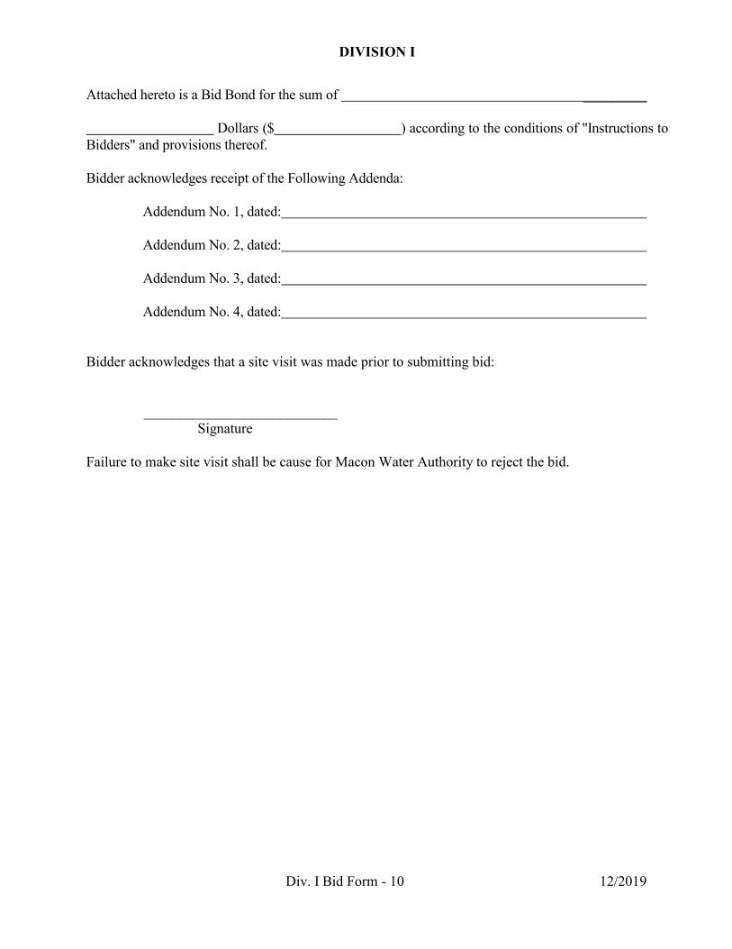
Attached hereto is a Bid Bond for the sum of _________ Dollars ($ ) according to the conditions of "Instructions to Bidders" and provisions thereof. Bidder acknowledges receipt of the Following Addenda: Addendum No. 1, dated: Addendum No. 2, dated: Addendum No. 3, dated: Addendum No. 4, dated:
Bidder acknowledges that a site visit was made prior to submitting bid:
___________________________ Signature
Failure to make site visit shall be cause for Macon Water Authority to reject the bid.

DIVISION I
Div. I Bid Form - 11 12/2019
BIDDER: By: Name: (Print or Type) Title: Address: Phone: Attest: Name: (Print or Type) Title:
(SEAL) Note: Attest for a corporation must be by the corporate secretary; for a partnership by another partner; for an individual by a notary. Note: If the Bidder is a corporation, the Bid shall be signed by an officer of the corporation; if a partnership, it shall be signed by a partner. If signed by others, authority for signature shall be attached. The full names and addresses of persons or parties interested in the foregoing Bid, as principals, are as follows:
Name Address
END OF DIVISION I BID

DIVISION II
Div. II Bid Form - 1
SECTION 00300.2
BID FORMS
For
DIVISION II –
WATER SYSTEM IMPROVEMENTS
ATLANTIC MILLS TANK CONNECTION TO SYSTEM

DIVISION II
Div. II Bid Form - 2 12/2019
BID TO: MACON WATER AUTHORITY FROM: (Bidder's Name) FOR: Division II – Water System Improvements – Atlantic Mills Tank Connection to System Submitted: , 202__ The undersigned Bidder, in compliance with your Invitation to Bid for the construction of this Project,
having examined the Contract Documents and the site of the proposed Work, and being familiar with
all of the conditions surrounding the construction of the proposed Project, including the availability of
materials and labor, hereby proposes to construct the Project in accordance with the Contract
Documents.
The Bidder proposes and agrees, if this Bid is accepted, to contract with the Macon Water Authority, in
the form of Contract Agreement specified, to furnish all necessary products, machinery, tools,
apparatus, means of transportation and labor necessary to complete the construction of the Work in full
and complete accordance with the reasonably intended requirements of the Contract Documents to the
full and entire satisfaction of the Macon Water Authority with a definite understanding that no money
will be allowed for extra work except as set forth in the Contract Documents, for the following prices:

DIVISION II
Div. II Bid Form - 3 12/2019
I. SCHEDULE OF BID PROPOSAL
Division II - Distribution System Piping
Item No. Qty. Unit Description Unit Price Total Price Erosion Control Items
2030 TBD CY
Gravel for Trench Stabilization & Other Miscellaneous Applications, as directed
by Engineer NOTE: Pipe bedding material is included with the pipe pay
item
$ $
Trench & Subgrade Preparation (where poor soils are encountered) 2111.1 10 CY Trench Rock Removal (Base Charge) $60.00 $600.00
2111.2 10 CY Trench Rock Removal (Contractor's additional unit price charge above
$60.00/CY) $ $
2115 10 CY Surge Stone to Replace Unsuitable Trench Material (to be authorized by
Engineer prior to work) $ $
2120 250 SF Filter Fabric to Use with Surge Stone (to be authorized by Engineer prior to
work) $ $
2125 20 CY Select Backfill Material (to be authorized by Engineer prior to work)
$ $
Utiltiy Items - General 2301 Lump LS Utility relocation coordination activities $ Lump Sum $
- Division II Base Bid Items Continued (on next page) -

DIVISION II
Div. II Bid Form - 4 12/2019
Item No. Qty. Unit Description Unit Price Total Price Utiltiy Items - Water Main Installation
2424 TBD LF
Furnish & Install 24" ANSI/AWWA C150/A21.50 DIP (Pressure Class 350)
Water Main $ $
2436 TBD LF Furnish & Install 36" ANSI/AWWA
C150/A21.50 DIP (Pressure Class 350) Water Main
$ $
2506 TBD EA 6" MJ Gate Valve w/ Box $ $
2524 TBD EA 24" MJ Gate Valve w/ Box $ $
2536 TBD EA 36" MJ Gate Valve w/ Box $ $
2624 TBD EA Connection to 24" Water Main $ $
2636 TBD EA Connection to (Division I) 36" Water Main $ $
2654 TBD Lbs DI Fittings w/ Concrete Thrust Blocks $ $
2658 TBD EA 3-Way Fire Hydrant Assembly $ $
Utiltiy Items - Water System Items to be Used as Needed to Resolve Conflicts (Upon Engineer Authorization)
2406 TBD LF Furnish & Install 6" ANSI/AWWA
C150/A21.50 DIP (Pressure Class 350) Water Main
$ $
2408 TBD LF Furnish & Install 8" ANSI/AWWA
C150/A21.50 DIP (Pressure Class 350) Water Main
$ $
2508 TBD EA 8" MJ Gate Valve w/ Box $ $
2606 TBD EA Connection to 6" Water Main $ $
2608 TBD EA Connection to 8" Water Main $ $
2672 TBD EA 3/4" Transfer of Service (at existing main) $ $
2674 TBD EA 3/4" Transfer of Service (at existing meter) $ $
2676 TBD LF Water Service Line, 3/4 Inch (Copper) $ $
- Division II Base Bid Items Continued (on next page) -

DIVISION II
Div. II Bid Form - 5 12/2019
Item No. Qty. Unit Description Unit Price Total Price
Utiltiy Items - Sanitary Sewer System Items to be Used as Needed to Resolve Conflicts (Upon Engineer Authorization)
2705 TBD LF 8" PVC Pipe, SDR 26 -- all depth cuts $ $
2710 TBD VF
Furnish and Install Manholes: Base Sections (variable diameters); 4'
Diameter Manhole Riser Sections; Transition Sections; Top Cone
Sections; Miscellaneous Sections
$ $
2712 TBD EA Furnish and Install Manhole Ring and
Cover, all types (Standard, Traffic, Watertight, Watertight Traffic)
$ $
Utiltiy Items - Storm Drain System Items to be Used as Needed to Resolve Conflicts (Upon Engineer Authorization)
2815 TBD LF 550-1150 Storm Drain Pipe, 15" RCP -- all depths $ $
2818 TBD LF 550-1180 Storm Drain Pipe, 18" RCP -- all depths $ $
2824 TBD LF 550-1240 Storm Drain Pipe, 24" RCP -- all depths $ $
Restoration Civil Items
2859 TBD TN 310-1101 Graded Aggregate Base Course, Incl. Material
$ $
2860 TBD LF 441-5002 Concrete Header Curb, 6", Type 2 $ $
2865 TBD SY 441-0104 Concrete Sidewalk, 4" $ $
2870 TBD SY 441-0016 Driveway Concrete, 6 Inches Thick $ $
2875 TBD SY 439-0018 Plain PC Concrete
Pavement, Class 3 Concrete, 8 Inches Thick
$ $
2880 TBD LF Salvage & Reset Granite Header Curb
$ $
- Division II Base Bid Items Continued (on next page) -

DIVISION II
Div. II Bid Form - 6 12/2019
Item No. Qty. Unit Description Unit Price Total Price
Miscellaneous Items 2991 Lump LS Traffic Control $ Lump Sum $
2995 Lump LS Provide Record Documents in
accordance with Specification Section 01720
$ Lump Sum $
2996 Lump LS Allowance -- Utility Relocation Costs $ Lump Sum $25,000.00 2999 Lump LS General Engineering Allowance $ Lump Sum $25,000.00
TOTAL DIVISION II BID - (Items 2000 - 2099)
$
Total Bid for Project (Division II) inclusive in the amount of
________________________________________________________________________________________________
________________________________________________________________________________________________
__________________________________________________________________________________________ Dollars
($______________________________________) which sum hereinafter is called the “Base Bid”.

DIVISION II
Div. II Bid Form - 7 12/2019
TABULATION OF SUBCONTRACTORS USED IN BID PROPOSAL The following tabulation lists the various Contractors whose prices were used in preparation of the Bid and who will be used to accomplish the respective items of work.
NAME AND ADDRESS OF DESCRIPTION OF WORK SUBCONTRACTORS INCLUDED Erosion Control ___________________________ Piping ___________________________ Concrete Construction ___________________________ Grassing ___________________________ ___________________________ ___________________________ ___________________________ ___________________________
DIVISION II
Div. II Bid Form - 8 12/2019
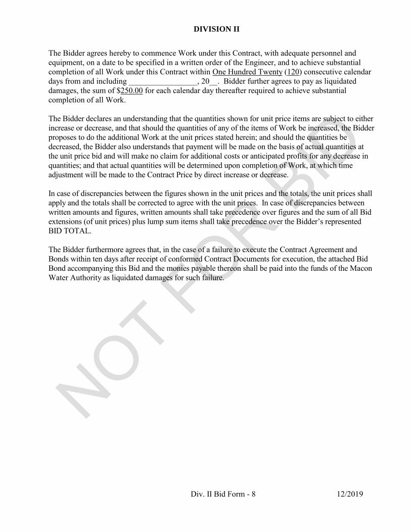
The Bidder agrees hereby to commence Work under this Contract, with adequate personnel and equipment, on a date to be specified in a written order of the Engineer, and to achieve substantial completion of all Work under this Contract within One Hundred Twenty (120) consecutive calendar days from and including _________________, 20__. Bidder further agrees to pay as liquidated damages, the sum of $250.00 for each calendar day thereafter required to achieve substantial completion of all Work. The Bidder declares an understanding that the quantities shown for unit price items are subject to either increase or decrease, and that should the quantities of any of the items of Work be increased, the Bidder proposes to do the additional Work at the unit prices stated herein; and should the quantities be decreased, the Bidder also understands that payment will be made on the basis of actual quantities at the unit price bid and will make no claim for additional costs or anticipated profits for any decrease in quantities; and that actual quantities will be determined upon completion of Work, at which time adjustment will be made to the Contract Price by direct increase or decrease. In case of discrepancies between the figures shown in the unit prices and the totals, the unit prices shall apply and the totals shall be corrected to agree with the unit prices. In case of discrepancies between written amounts and figures, written amounts shall take precedence over figures and the sum of all Bid extensions (of unit prices) plus lump sum items shall take precedence over the Bidder’s represented BID TOTAL. The Bidder furthermore agrees that, in the case of a failure to execute the Contract Agreement and Bonds within ten days after receipt of conformed Contract Documents for execution, the attached Bid Bond accompanying this Bid and the monies payable thereon shall be paid into the funds of the Macon Water Authority as liquidated damages for such failure.

DIVISION II
Div. II Bid Form - 9 12/2019
Attached hereto is a Bid Bond for the sum of _________ Dollars ($ ) according to the conditions of "Instructions to Bidders" and provisions thereof. Bidder acknowledges receipt of the Following Addenda: Addendum No. 1, dated: Addendum No. 2, dated: Addendum No. 3, dated: Addendum No. 4, dated:
Bidder acknowledges that a site visit was made prior to submitting bid:
___________________________ Signature
Failure to make site visit shall be cause for Macon Water Authority to reject the bid.

DIVISION II
Div. II Bid Form - 10 12/2019
BIDDER: By: Name: (Print or Type) Title: Address: Phone: Attest: Name: (Print or Type) Title:
(SEAL) Note: Attest for a corporation must be by the corporate secretary; for a partnership by another partner; for an individual by a notary. Note: If the Bidder is a corporation, the Bid shall be signed by an officer of the corporation; if a partnership, it shall be signed by a partner. If signed by others, authority for signature shall be attached. The full names and addresses of persons or parties interested in the foregoing Bid, as principals, are as follows:
Name Address
END OF DIVISION II BID

1 06/2015
SECTION 00410 BID BOND
STATE OF GEORGIA COUNTY OF BIBB KNOW ALL MEN BY THESE PRESENTS, that we, , as Principal, and , as Surety, are held and firmly bound unto the Owner, the Macon Water Authority, in the sum of __________________________ __________________ Dollars ($ ) lawful money of the United States of America, for the payment of which sum well and truly to be made, we bind ourselves, our heirs, personal representatives, successors and assigns, jointly and severally, firmly by these presents. WHEREAS, the Principal has submitted to the Owner a Bid for the Division I - Atlantic Mills 3,000,000 Gallon Composite Elevated Tank. NOW THEREFORE, the conditions of this obligation are such that if the Bid be accepted, the Principal shall, within ten days after receipt of conformed Contract Documents, execute a Contract in accordance with the Bid upon the terms, conditions and prices set forth therein, and in the form and manner required by the Contract Documents and execute sufficient and satisfactory separate Performance and Payment Bonds payable to the Owner, each in an amount of 100 percent of the total Contract Price, in form satisfactory to the Owner , then this obligation shall be void; otherwise, it shall be and remain in full force and effect in law; and the Surety shall, upon failure of the Principal to comply with any or all of the foregoing requirements within the time specified above, immediately pay to the aforesaid Owner, upon demand, the amount hereof in good and lawful money of the United States of America, not as a penalty, but as liquidated damages. This bond is given pursuant to and in accordance with the provisions of the Georgia Local Government Public Works Construction Law, O.C.G.A. § 36-91-1 et. seq., and all the provisions of the law referring to this character of bond as set forth in said Sections or as may be hereinafter enacted and these are hereby made a part hereof to the same extent as if set out herein in full.
[Remainder of Page Left Blank]

00410-2 Bid Bond
2 06/2015
IN WITNESS WHEREOF, the said Principal has hereunder affixed its signature and seal, and said Surety has hereunto caused to be affixed its corporate signature and seal, by its duly authorized officers, on this day of ____________ , 20__. CONTRACTOR - PRINCIPAL: By: Name: (Print or Type) Address: Phone: Attest: Name: (Print or Type) Title: (SEAL) Note: Attest for a corporation must be by the corporate secretary; for a partnership by another partner; for an individual by a notary. SURETY: By: Name: (Print or Type) Title: Phone: Attest: Name: (Print or Type) Title: (SEAL) Note: Surety companies executing bonds must appear on the Treasury Department's most current list (Circular 570 as amended) and be authorized to transact business in the state where the Project is located.
END OF SECTION

1 06/2015
SECTION 00420 STATEMENT OF BIDDER’S QUALIFICATIONS
All questions must be answered and the data given must be clear and comprehensive. This statement must be notarized. If necessary, questions may be answered on separate attached sheets. The Bidder may submit any additional information desired. Attach all additional sheets to this statement. 1. Name of Bidder: 2. Permanent main office address: 3. When organized: 4. If a Corporation, where incorporated: 5. How many years have you been engaged in the contracting business under your present firm or trade name? 6. Contracts on hand: (Schedule these, showing amount of each contract and the appropriate
anticipated dates of completion): 7. General description of type of work performed by your company: 8. Have you ever failed to complete any work awarded to you? If so, where and why? 9. Have you ever defaulted on a contract? If so, where and why? 10. Attach a list of the most important projects recently completed by your company which are
similar in scope to this Project. For each project, list its: official name and owner, a contact person's name, company and position, address and phone number; completion date; and contract amount.
11. Names, background and experience of the principal members of your organization, including
officers:

00420-2 Statement of Bidder’s Qualifications
2 06/2015
12. The undersigned hereby authorizes and requests any person, firm, or corporation to furnish any information requested by the Owner in verification of the recitals comprising this Statement of Bidder's Qualifications.
Dated this day of , 200__. BIDDER: By: Title: State of County of being duly sworn deposes and says that he or she is of and that the answers to the foregoing questions and all statements therein contained are true and correct. Subscribed and sworn to before me this day of , 20__. Notary Public: (SEAL) My Commission Expires: (Date) END OF SECTION

1 06/2015
SECTION 00421 STATEMENT OF EQUIPMENT
Show machinery and other equipment available to the Bidder for prosecuting the Work required by the Contract Documents. (To be filled in by Bidder and submitted with Bid.)
Available Machinery and Other Equipment
Kind - Size - Capacity
Location
Ownership
Date Proposed To Be Placed
On Work The above is a true statement of the equipment available to the undersigned Bidder for prosecuting the Work required by the Contract Documents. Where it is shown that the equipment is not owned by the Bidder, arrangements have been made with the owners to furnish the equipment. Signed: Name: Title: END OF SECTION

1 06/2015
SECTION 00422 CORPORATE CERTIFICATE
I, , certify that I am the Secretary of the Corporation named as Bidder
in the foregoing Bid; that , who signed said Bid on behalf of the
Bidder was then of said Corporation; that said Bid was duly signed
for and on behalf of said Corporation by authority of its Board of Directors, and is within the scope
of its corporate powers; that said Corporation is organized under the laws of the State of
.
This day of , 20___.
(Corporate Secretary) (SEAL) END OF SECTION

1 06/2015
SECTION 00423 STATEMENT OF MINORITY OWNED FIRM UTILIZATION
The Bidder shall list all minority firms providing subcontracting services, furnishing products or materials, etc., to be utilized in the performance of the work. This list shall be submitted in the following format:
Subcontractor (Name & Address)
Nature of Work to be Contracted
Group (Local, MBE)
Anticipated Cost of Services
($ Value, %)
$
%
$
%
$
%
$
%
$
%
$
%
$
%
$
%
$
%
NOTE: Any proposed changes from the above list shall be submitted in writing to the Owner
prior to initiation of the action, with the reason for the proposed deviation. END OF SECTION

1 06/2015
SECTION 00425 CONTRACTOR’S LICENSE CERTIFICATION
Contractor's Name: Georgia Contractor's License Number: Expiration Date of License: I certify that the above information is true and correct and that the classification noted is applicable to the Bid for this Project. Signed: Printed: Date: END OF SECTION

SECTION 00430
1 06/2015
CONTRACTOR’S CERTIFICATION OF AUTHORITY
(IF OUT OF STATE CONTRACTOR) Contractor's Name: Georgia Certificate of Authority Number: Expiration Date of Certificate: I certify that the above information is true and correct and that the classification noted is applicable to the Bid for this Project. Signed: Printed: Date: END OF SECTION

1 06/2015
SECTION 00480 NON-COLLUSION AFFIDAVIT OF PRIME BIDDER
STATE OF GEORGIA COUNTY OF ___________ , being first duly sworn, deposes and says that: He or she is (Owner, Partner, Officer, Representative or Agent) of , the Bidder that has submitted the attached Bid; He or she is fully informed respecting the preparation and contents of the attached Bid and of all pertinent circumstances respecting such Bid; Such Bid is genuine and is not a collusive or sham Bid; Neither the said Bidder nor any of its officers, partners, owners, agents, representatives, employees or parties in interest, including this Affiant, has in any way colluded, conspired, connived or agreed, directly or indirectly with any other Bidder, firm or person to submit a collusive or sham Bid in connection with the Contract for which the attached Bid has been submitted or to refrain from bidding in connection with such Contract, or has in any manner, directly or indirectly, sought by agreement or collusion or communication or conference with any other Bidder, firm or person to fix the price or prices in the attached Bid or of any other Bidder, or to fix any overhead, profit or cost element of the Bid price or the Bid price of any other Bidder, or to secure through any collusion, conspiracy, connivance or unlawful agreement any advantage against the Macon Water Authority (“Owner”) or any person interested in the proposed Contract; and The price or prices quoted in the attached Bid are fair and proper and are not tainted by any collusion, conspiracy, connivance or unlawful agreement on the part of the Bidder or any of its agents, representatives, owners, employees, or parties in interest, including this Affiant. (Signed) (Title) Subscribed and Sworn to before me this day of , 200__. My Commission Expires: (Notary Public) (SEAL) Note: If the Bidder is a partnership, all of the partners and any officer, agent or other person who may have represented or acted for the partnership shall also make the foregoing oath. If the Bidder is a corporation, all officers, agents, or other persons who may have acted for or represented the corporation shall also make the oath. END OF SECTION

1 06/2015
SECTION 00500 CONTRACT AGREEMENT
AGREEMENT BETWEEN CONTRACTOR AND OWNER THIS AGREEMENT made the __ day of _________ in the year Two Thousand and ____ (20__) by and between _ , hereinafter called the Contractor, and THE MACON WATER AUTHORITY (the “Owner”), as follows. WITNESSETH, that the Contractor and the Owner, for the consideration hereinafter named, agree as follows: 1. SCOPE OF WORK. - That the Contractor will furnish all products, tools, construction equipment, skill and labor of every description necessary to carry out and to complete in a good, firm, substantial workmanlike manner perform the Division I - Atlantic Mills 3,000,000 Gallon Composite Elevated Tank project and will complete the Work in strict conformity with the Drawings and the Specifications, together with the foregoing Bid made by the Contractor, the Invitation to Bid, Instructions to Bidders, General and Supplementary Conditions, Special Conditions, Performance and Payment Bonds and all Addenda hereto incorporated (if applicable) which form essential parts of this Contract Agreement, as if fully contained herein. 2. TIME OF COMPLETION.-The Contractor shall commence the Work to be performed under this Contract Agreement on a date to be specified in a written Notice to Proceed and shall achieve substantial completion of all Work required by the Contract Documents within four hundred fifty (450) consecutive calendar days (the “Contract Time”). Time is of the essence and is an essential element of this Contract, and the Contractor shall pay to the Owner, not as a penalty, but as liquidated damages, the sum of Two Hundred and Fifty Dollars ($250.00) for each calendar day for which there is an unexcused delay in achieving substantial completion of the Work within the time limit set forth herein. These liquidated damages are not established as a penalty but are calculated and agreed upon in advance by the Owner and the Contractor due to the uncertainty and impossibility of making a determination as to the actual and consequential damages incurred by the Owner and the general public of Bibb County, Georgia as a result of the failure on the part of the Contractor to complete the Work on time. Such liquidated damages referred to herein are intended to be and are cumulative and shall be in addition to every other remedy now or hereafter enforceable at law, in equity, by statute, or under the Contract Documents. 3. THE CONTRACT PRICE.-The Owner shall pay to the Contractor for the faithful performance of the Contract Agreement, subject to additions and deductions as provided for in the Contract Documents, in current funds a sum of _____________________________________ Dollars ($___________.00) (the “Contract Price”) which sum shall also pay for loss or damage arising out of the nature of the Work aforesaid, or from the action of the elements, or from unforeseen obstructions or difficulties encountered in the prosecution of the Work, and for all expenses incurred by, or in consequence of the Work, its suspension or discontinuance and for well and faithfully completing the Work and the whole thereof, as herein provided, and for replacing defective Work or products for a period of one year after completion.

00500-2 Contract Agreement
2 06/2015
4. PROGRESS PAYMENTS The Owner shall make progress payments on account of the Contract Price as follows: On or about the 20th day of each month, ninety percent (90%) of the value, based on the contract prices, of labor and materials incorporated in the Work and of materials suitably stored at the site thereof up to the twenty-fifth day of the month preceding, as estimated by the Engineer, less the aggregate of previous payments, until one-half of the contract sum is due. Application for Payment must be made on standard Owner’s form to be provided by the Owner to the Contractor. If the Work is- (a) On or ahead of the Construction Progress Schedule; and (b) There are no breaches of Orders of Condemnation, and (c) There is no delinquency in the filing of the final breakdown and accounting, together
with vouchers, on force account work as referred to in Article 29 of the General Conditions, then no further retainage will be withheld by the Owner from payments to the Contractor unless- Event (a) The Engineer determines that Work is unsatisfactory or has fallen behind
the Construction Progress Schedule, or Event (b) The Contractor breaches an Order of Condemnation, or Event (c) The Contractor becomes delinquent in regard to the filing of the final
breakdown and accounting, together with vouchers, on force account work as referred to in Article 29 of the General Conditions; or
Event (d) The Contract Time has expired. in which event or events the Owner shall reinstate the ten percent (10%) retainage on all subsequent progress payments. No form of collateral in lieu of cash will be acceptable as retainage. At the discretion of the Owner, the retainage of each Subcontractor may be released separately as he completes his work. An application for release of a Subcontractor’s retainage shall bear the certificates of the Subcontractor, the Contractor, and the Engineer that the Subcontractor’s work has been fully performed and that the sum for which payment is requested is due by the Contractor to the Subcontractor. Checks releasing a Subcontractor’s retainage shall be made payable to the Contractor, the Contractor's surety, and the Subcontractor and shall be mailed to the Contractor's surety. This Article does not create any contractual relationship between the Owner and the Subcontractor or any duty of the Owner to any Subcontractor. Payments pursuant to this Article shall in no way diminish, change, alter or affect the rights of the Owner under the Contract Documents. 5. FINAL PAYMENT.-(a)-Final payment shall be due 30 days after the date of notice from the Agent of the final acceptance of the Work, provided that all other requirements of the Contract Documents shall have been met in full. Final payment shall be made by a check payable jointly to the Contractor and surety and shall be mailed to the surety.

Section 00500-3 Contract Agreement
3 06/2015
(b)-Upon receipt of written notice from the Contractor pursuant to Article 30 of the General Conditions that the Work is ready for final inspection, the Engineer shall promptly make such inspection, and when he finds the Work complies with the contract and when the contract shall have been fully performed he shall promptly issue a recommendation to the Owner, over his signature, stating that the Work required by the Contract Documents has been completed under the terms and conditions thereof, and that the entire balance found to be due to the Contractor and noted in said final certificate, is due and payable. (c)-Before issuance of a final recommendation, the Contractor shall submit evidence satisfactory to the Engineer that all payrolls, material bills, and all other indebtness in connection with the Work has been paid. (d)-If full completion of the Work is materially delayed through no fault of the Contractor, and the Engineer so certifies same, the Owner shall, upon certificate of the Engineer, and without terminating the Contract, make payment of the balance due for that portion of the Work fully completed. Such payment shall be made under the terms and conditions of the General Conditions governing final payment, except that it shall not constitute a waiver of claims. 6. BONDS.-The Contractor shall furnish both a performance bond and a payment bond and shall pay the premium thereon. The performance bond shall guarantee the full performance of the Contract.
Remainder of Page Left Blank [Signatures on Following Page]

00500-4 Contract Agreement
4 06/2015
IN WITNESS WHEREOF, the parties hereto have executed this Contract Agreement under their respective seals on the day and date first above written in six counterparts each of which shall, without proof or accounting for the other counterparts, be deemed an original Contract. Signed, sealed and delivered THE MACON WATER AUTHORITY in the presence of: 1.________________________ By: Samuel F. Hart, Sr., Chairman 2.________________________ Attest: R. A. “Tony” Rojas, Executive Director (Official Seal) Signed, sealed and delivered CONTRACTOR: in the presence of: 1.________________________ By: (Signed) 2.________________________ (Printed) Attest: (Signed) (Printed) (Secretary) (Corporate Seal) APPROVED AS TO FORM (Printed Name) Attorney for the Macon Water Authority END OF SECTION

1 06/2015
SECTION 00550 PRE-AWARD OATH
STATE OF GEORGIA COUNTY OF ____________ In accordance with O.C.G.A. 36-91-21(e), we, the undersigned of being first duly sworn, deposes and says that: We have not directly or indirectly violated O.C.G.A. 36-91-21(d), and more specifically, we have not - prevented or attempted to prevent competition in such bidding or proposals by any means
whatever, - prevented or endeavored to prevent anyone from making a bid or proposal thereof by any
means whatever, nor - caused or induced another to withdraw a bid or proposal for the work. We, the undersigned, to the best of our knowledge, affirm that no other officers, agents or other persons acted for or represented the Contractor in the bidding for and procurement of this Contract.
Signature Printed Name Title Date
My Commission Expires:
(Notary Public)
(SEAL) END OF SECTION

1 06/2015
SECTION 00600 PERFORMANCE BOND
Bond No. KNOW ALL MEN BY THESE PRESENTS: That ____________________________________________________________________________ (Legal title and address of the Contractor) as Principal (hereinafter referred to as “Contractor”), and (Legal title and address of Surety) as Surety (hereinafter referred to as “Surety”), do hereby acknowledge ourselves indebted and firmly bound and held unto the Macon Water Authority (the “Owner”) in the amount of __________ Dollars and Cents ($___________.00) to which payment Contractor and Surety bind themselves, their heirs, executors, administrators, successors and assigns, jointly and severally, firmly by these presents. WHEREAS, the above bounden Principal has entered into a Contract with Owner bearing date of _______________ for construction Division I - Atlantic Mills 3,000,000 Gallon Composite Elevated Tank Project in accordance with Contract Documents prepared by Owner which said Contract Documents are incorporated herein by reference and made a part hereof, and is hereinafter referred to as the “Contract”. NOW THEREFORE, THE CONDITION OF THIS OBLIGATION is such that, if the Contractor shall promptly and faithfully perform and comply with the terms and conditions of said Contract; and shall indemnify and save harmless the Owner against and from all costs, expenses, damages, injury or loss to which said Owner may be subjected by reason of any wrongdoing, including patent infringement, misconduct, want of care or skill, default or failure of performance on the part of said Principal, his agents, subcontractors of employees, in the execution or performance of said Contract, and shall fully reimburse and repay the said Owner any and all outlay, costs, and expense which it may incur in making good any such default and shall guarantee all products and workmanship against defects, as defined in said Contract Documents, for a period of one year and shall replace all defective work and products for such period of one year then this obligation shall be null and void; otherwise it shall remain in full force and effect. 1. The said Surety to this bond, for value received, hereby stipulates and agrees that no change
or changes, extension of time or extensions of time, alteration or alterations or addition or additions to the terms of the Contract or to the work to be performed thereunder, or the specifications or drawings accompanying same shall in any wise affect its obligations on this bond, and it does hereby waive notice of any such change or changes, extension of time or extensions of time, alteration or alterations or addition or additions to the terms of the Contract or to the Work or to the specifications or drawings.

00600-2 Performance Bond
2 06/2015
2. It is expressly agreed that this bond shall be amended automatically and immediately, without formal and separate amendments hereto, upon amendment to the Contract not increasing the Contract Price more than 20 percent in excess of the original Contract Price, so as to bind the Principal and Surety to the full and faithful performance of the Contract as so amended. The term “amendment” shall include any alteration, addition, extension, or modification of any character whatsoever.
3. If pursuant to the Contract Documents the Contractor shall be declared in default by the
Owner under the aforesaid Contract, the Owner shall take possession of the Project and finish the Work by whatever method the Owner may deem expedient, in accordance with Article 7 of the General Conditions.
4. Supplementary to and in addition to the foregoing, whenever the Owner shall notify the
Surety that the Owner has notice that the Contractor has failed to pay any subcontractor, materialman, or laborer for labor or materials certified by the Contractor as having been paid for by the Contractor, the Surety shall, within thirty (30) days of receipt of such notice, cause to be paid any unpaid amount for such labor or materials.
5. It is expressly agreed by the Principal and the Surety that the Owner, if it desires to do so, is at
liberty to make inquiries at any time of subcontractors, laborers, materialmen, or other parties concerning the status of payments for labor, materials, or services furnished in the prosecution of the work.
6. The Surety agrees that other than as is provided in this bond it may not demand of the Owner
that the Owner shall (a) perform any thing or act, (b) give any notice, (c) furnish any clerical assistance, (d) render any service, (e) furnish any papers or documents, or (f) take any action of any nature or description which is not required of the Owner to be done under the Contract Documents.
7. No right of action shall accrue on this bond to or for the use of any person or corporation
other than the Owner named herein or the legal successors of the Owner. This bond is given pursuant to and in accordance with the provisions of Part 3 of Chapter 91 of Title 36 of the Official Code of Georgia Annotated and all the provisions of the law referring to this character of bond as set forth in said sections or as may be hereafter enacted or amended and these are hereby made a part hereof to the same extent as if set out in full herein.
Remainder Of Page Left Blank

00600-3 Performance Bond
3 06/2015
Signed and sealed this _______ day of _____________________________ A.D. 20__. Signed, sealed and delivered in the presence of: (Insert Name of Contractor) By: (Signed) 1. __________________________________ (Printed) 2. __________________________________ Attest:(Signed) (Printed) (CORPORATE SEAL) Signed, sealed and delivered in the presence of: (Insert Name of Surety) By: (Signed) 1. __________________________________ (Printed) 2. __________________________________ Attest:(Signed) (Printed) (CORPORATE SEAL) APPROVED AS TO FORM: (Printed Name) Attorney for the Macon Water Authority END OF SECTION

PLACE SURETY FOR PERFORMANCE BOND HERE

1 06/2015
SECTION 00610 PAYMENT BOND
Bond No. KNOW ALL MEN BY THESE PRESENTS: That _____________________________________________________________________________ (Legal title and address of the Contractor) as Principal (hereinafter referred to as “Contractor”), and (Legal title and address of Surety) as Surety (hereinafter referred to as “Surety”), do hereby acknowledge ourselves indebted and firmly bound and held unto the Macon Water Authority (the “Owner”), in the amount of ________________ Dollars Cents ($___________.00) to which payment Contractor and Surety bind themselves, their heirs, executors, administrators, successors and assigns, jointly and severally, firmly by these presents. WHEREAS, the above bounden Principal has entered into a Contract with Owner bearing date of __________________ for construction of Division I - Atlantic Mills 3,000,000 Gallon Composite Elevated Tank Project in accordance with the Contract Documents prepared by Owner which said Contract Documents are incorporated herein by reference and made a part hereof, and is hereinafter referred to as the “Contract”. NOW THEREFORE, THE CONDITION OF THIS OBLIGATION is such that if the Contractor shall promptly make payment to all claimants as hereinafter defined, for all labor and material supplied in the prosecution of the work provided for in said Contract Documents, then this obligation shall be void; otherwise it shall remain in full force and effect, subject, however, to the following conditions: 1. The said Surety to this bond, for value received, hereby stipulates and agrees that no change
or changes, extension of time or extensions of time, alteration or alterations or addition or additions to the terms of the Contract or to the work to be performed thereunder, or the specifications or drawings accompanying same shall in any wise affect its obligations on this bond, and it does hereby waive notice of any such change or changes, extension of time or extensions of time, alteration or alterations or addition or additions to the terms of the Contract or to the work or to the specifications or drawings.
2. It is expressly agreed that this bond shall be amended automatically and immediately, without
formal and separate amendments hereto, upon amendment to the Contract Documents not increasing the Contract Price more than 20 percent in excess of the original Contract Price, so as to bind the Contractor and Surety to the full and faithful performance of the Contract as so amended. The term “amendment” shall include any alteration, addition, extension, or modification of any character whatsoever.

00610-2 Payment Bond
2 06/2015
3. A Claimant is defined as any subcontractor and any person supplying labor, materials, machinery, or equipment in the prosecution of the work provided for in said Contract.
4. Every person entitled to the protection hereunder and who has not been paid in full for labor
or materials furnished in the prosecution of the work referred to in said bond before the expiration of a period of ninety days after the day on which the last of the labor was done or performed by him, or materials or equipment or machinery was furnished or supplied by him for which such claim is made, or when he has completed his subcontract for which claim is made, shall have the right to sue on such payment bond for the amount, or the balance thereof, unpaid at the time of the commencement of such action and to prosecute such action to final execution and judgment for the sum or sums due him; provided, however, that any person having direct contractual relationship with a subcontractor, but no contractual relationship express or implied with the Contractor, shall have the right of action upon the said payment bond upon giving written notice to said Contractor within ninety days from the day on which such person did or performed the last of the labor, or furnished the last of the materials or machinery or equipment for which such claim is made, stating with substantial accuracy the amount claimed and the name of the party to whom the materials were furnished or supplied or for whom the labor was performed or done; provided further that nothing contained herein shall limit the right of action to said 90-day period. Notice may be served by depositing a notice, registered mail, postage prepaid, duly addressed to the Contractor at any place he maintains an office or conducts his business, or his residence, in any post office or branch post office or any letter box under the control of the United States Postal Service, or notice may be served in any manner in which the sheriffs of Georgia are authorized by law to serve summons or process.
5. Every suit instituted under this section shall be brought in the name of the claimant without
the Owner being made a party thereto. The official who has the custody of said bond is authorized and directed to furnish, to any person making application therefor who submits an affidavit that he has supplied labor or material for such work and payment therefor has not been made, or that he is being sued on any such bond, a copy of such bond and the Contract for which it was given, certified by the official who has custody of said bond; this copy shall be primary evidence of said bond and Contract and shall be admitted as evidence without further proof. Applicants shall pay for such certified copies and such certified statements such as fees as the official fixes to cover the cost of preparation thereof, but in no case shall the fee exceed the fees which the clerks of the superior courts are permitted to charge for similar copies.
6. No action can be instituted on this bond after one year from the date of the final acceptance of
the Owner. This bond is given pursuant to and in accordance with the provisions of Part 4 of Chapter 91 of Title 36 of the Official Code of Georgia Annotated and all the provisions of the law referring to this character of bond as set forth in said sections or as may be hereafter enacted or amended and these are hereby made a part hereof to the same extent as if set out in full herein.

00610-3 Payment Bond
3 06/2015
Signed and sealed this __________day of _____________ A.D. 200__ Signed, sealed and delivered in the presence of: (Insert Name of Contractor) By: (Signed) 1. __________________________________ (Printed) 2. __________________________________ Attest:(Signed) (Printed) (CORPORATE SEAL) Signed, sealed and delivered in the presence of: (Insert Name of Surety) By: (Signed) 1. __________________________________ (Printed) 2. __________________________________ Attest:(Signed) (Printed) (CORPORATE SEAL) APPROVED AS TO FORM: (Printed Name) Attorney for the Macon Water Authority END OF SECTION

PLACE SURETY FOR PAYMENT BOND HERE

1 06/2015
SECTION 00700
GENERAL CONDITIONS Article 1. - Notice of Award of Contract. ....................................................................... 00700-2 Article 2. - Execution of Contract Documents................................................................ 00700-2 Article 3. - Contract Security. .......................................................................................... 00700-2 Article 4. - Insurance. ...................................................................................................... 00700-3 Article 5. - Hazards and Indemnification. ....................................................................... 00700-5 Article 6. - Notice to Proceed. ......................................................................................... 00700-6 Article 7. - Termination of Work for Default. ................................................................ 00700-7 Article 8. - Termination for Convenience of Owner. ..................................................... 00700-8 Article 9. - Assignments. ................................................................................................. 00700-8 Article 10. - Subcontractors, Materialmen, Suppliers and Employees. .......................... 00700-8 Article 11. - Engineer. ................................................................................................... 00700-11 Article 12. - Separate Contracts. ................................................................................... 00700-13 Article 13. - Laws and Regulations. .............................................................................. 00700-13 Article 14. - Taxes. ........................................................................................................ 00700-14 Article 15. - Notice and Service Thereof. ..................................................................... 00700-14 Article 16. - Patents and Royalties. ............................................................................... 00700-15 Article 17. - Land and Rights-of-Way........................................................................... 00700-15 Article 18. - Products. .................................................................................................... 00700-16 Article 19. - Supervision of Work. ................................................................................ 00700-17 Article 20. - Interruption of Facility Operations. .......................................................... 00700-18 Article 21. - Protection of Work, Property and Persons. .............................................. 00700-18 Article 22. - Protection of the Environment. ................................................................. 00700-19 Article 23. - Protection, Location and Relocation of Utilities. ..................................... 00700-19 Article 24. - Schedules, Reports and Records. .............................................................. 00700-20 Article 25. - Drawings and Specifications. ................................................................... 00700-22 Article 26. - Surveys and Permits .................................................................................. 00700-24 Article 27. - Testing, Inspection and Rejection of Work. ............................................. 00700-24 Article 28. - Contract Time and Liquidated Damages. ................................................. 00700-27 Article 29. - Changes in the Work................................................................................. 00700-28 Article 30. - Payments and Completion. ....................................................................... 00700-34 Article 31. - Certificates of Payment. ............................................................................ 00700-38 Article 32. - Payments Withheld. .................................................................................. 00700-39 Article 33. - Notice of Commencement. ....................................................................... 00700-40 Article 34. - Correction of Work after Final Payment. ................................................. 00700-40 Article 35. - Cash Allowances. ...................................................................................... 00700-41 Article 36. - Contractor's Warranty as to Performance. ................................................ 00700-41 Article 37. - Claims. ...................................................................................................... 00700-42 Article 38. - Use of Premises. ........................................................................................ 00700-43 Article 39. - Specification Arrangement. ...................................................................... 00700-43 Article 40. - Valuable Material, Geological Specimens ............................................... 00700-44 Article 41. - Definitions. ................................................................................................ 00700-44

00700-2 General Conditions
2 06/2015
Article 1. - Notice of Award of Contract. Within sixty (60) days after receipt of Bids, the Owner will notify the successful Bidder of the award of the Contract. Should the Owner require additional time to award a Contract, the time may be extended by the mutual agreement between the Owner and the successful Bidder. If an award of Contract has not been made within 60 days from the Bid date or within the extension mutually agreed upon, the Bidder may withdraw the Bid without further liability on the part of either party. Article 2. - Execution of Contract Documents. (a) Time Limits.—Within fifteen (15) days of notification of Award of Contract, the Owner will furnish the Contractor with conformed copies of Contract Documents for execution by the Contractor and the surety. The Contractor and its surety must execute the bond forms contained in the conformed Contract Documents without any changes. Within ten (10) days after receipt, the Contractor shall return all the Documents properly executed by the Contractor and the surety. Attached to each set of Contract Documents shall be an original power-of-attorney for the person executing the Bonds for the surety and certificates, endorsements and declarations of insurance for the required insurance coverages, all as required by Article 3 and Article 4. Within thirty (30) days after receipt of the conformed Contract Documents properly completed and executed by the Contractor and the surety together with the power-of-attorney, and the proper certificates, endorsements and declarations of insurance, the Owner will complete the execution of the Documents. Distribution of the completed Documents will be made upon execution by the Owner. (b) Failure of Contractor or Surety to Execute Documents.—Should the Contractor or the surety fail to properly execute the Documents within the specified time the Owner will have the right to proceed on the Bid Bond accompanying the Bid. (c) Failure of Owner to Execute Documents.—If the Owner fails to execute the Documents within the time limit specified, the Contractor will have the right to withdraw the Bid without penalty. In such event the Owner will have no liability to the Contractor under these Documents or otherwise. (d) Extensions of Time.—Should either party require an extension of any of the time limits stated above, this shall be done only by mutual agreement between both parties. Article 3. - Contract Security.—The Contractor shall furnish separate Performance and Payment Bonds each in a sum equal to the amount of the Contract Price on the forms set forth below. Such Bonds shall be executed by the Contractor and a corporate bonding company licensed to transact such business in Georgia and named on the current list of “Companies Holding Certificates of Authority as Acceptable Sureties on Federal Bonds” as published in the Treasury Department Circular Number 570. The expense of these Bonds shall be borne by the Contractor. If at any time a surety on any such Bond is declared bankrupt or loses its right to do business in Georgia or is removed from the list of Surety Companies accepted on Federal Bonds, the Contractor shall, within ten (10) days after notice from the Owner to do so, substitute an acceptable Bond (or Bonds) in such form and sum and signed by such other surety as may be satisfactory to the Owner.

Section 00700-3 General Conditions
3 06/2015
The premium on such Bond (or Bonds) shall be paid by the Contractor. No further progress payments shall be deemed due, nor shall be made, until the new surety furnishes an acceptable Bond to the Owner. The person executing the Bond on behalf of the surety shall file with the Bond a general power of attorney, unlimited as to amount and type of Bond covered by such power of attorney and certified to by an official of said surety company. Article 4. - Insurance—Proof of insurance coverage and furnishing of insurance policies acceptable to the Owner shall be as set forth in this Article. (a) Policies, Certificates, Limits and Disposition of Documents.—The Contractor shall obtain at his expense insurance with limits as shown hereinbelow, unless the Contractor desires to broaden the limits and obtain more protection. The Contractor shall provide the Owner with all insurance documentation and evidence of insurance as required herein, and updated certificates of all insurance required herein must be provided to the Owner at least quarterly until Final Payment. (1) WORKER'S COMPENSATION AND EMPLOYER’S LIABILITY INSURANCE.—The Contractor shall procure and maintain Worker's Compensation and Employers Liability Insurance for all of his employees to be engaged in Work on the project under this contract, and in case any such Work is sublet, the Contractor shall require the Subcontractor similarly to provide Worker's Compensation and Employer’s Liability Insurance for all of the latter's employees to be engaged in such work unless such employees are covered by the protection afforded by the Contractor's insurance. Worker's Compensation insurance policies shall include GEORGIA under Section 3A and shall include Other States coverage and Voluntary Compensation. Worker’s Compensation Limits: Statutory Employers Liability Limits: Each Accident $1,000,000 Disease - Policy Limit $1,000,000 Disease - Each Employee $1,000,000 Contractor waives all rights against Owner and its agents, officers, directors and employees for recovery of damages to the extent these damages are covered by the worker’s compensation and employers liability or commercial umbrella liability insurance obtained by Contractor pursuant to Article 4 of this agreement. The Waiver of Our right To Recover From Others Endorsement, ISO Form SC 00 03 13 shall be attached to the policy showing the Owner listed in the Schedule. DISPOSITION: Certificate(s) of insurance and copy of policy declaration page(s) must be returned to the Owner with properly executed Contract Documents. [See Article 2] (2) COMMERCIAL GENERAL AND UMBRELLA LIABILITY INSURANCE.—The Contractor shall procure and shall maintain commercial general liability (CGL) and if necessary, commercial umbrella insurance with a limit of not less that $2,000,000 each occurrence, as shall protect him and any Subcontractor performing Work covered by this Contract from claims for damages for bodily injury, including accidental death, as well as from claims for property damages, which may arise from operations under the Contract Agreement, whether such operations are by

00700-4 General Conditions
4 06/2015
himself or by any Subcontractor or by anyone directly or indirectly employed by either of them. CGL insurance shall be written on ISO occurrence form CG 00 01 10 93 (or substitute form providing equivalent coverage) and shall cover liability arising from premises, operations, independent contractors, products-completed operations, personal injury and advertising injury, and liability assumed under an insured contract (including the tort liability of another assumed in a business contract). If such CGL insurance contains a general aggregate limit, it shall apply separately to this project. Each policy shall be indorsed with ISO Form CG 25 03 11 85 or equivalent form with wording satisfactory to Owner. The Owner shall be included as an additional insured under the CGL, using ISO additional insured endorsement CG 20 33 or a substitute providing equivalent coverage, and under the commercial umbrella, if any. This insurance shall apply as primary insurance with respect to any other insurance or self-insurance programs afforded to the Owner. There shall be no endorsement or modification of the CGL limiting the scope of coverage for liability arising from explosion, collapse, or underground property damage. Contractor waives all rights against Owner and its agents, officers, directors and employees for recovery of damages to the extent these damages are covered by commercial general liability or commercial umbrella liability insurance maintained pursuant to Article 4 of this agreement. Disposition: Certificate(s) of insurance and a copy of the policy declaration(s) must be sent returned to the Owner with properly executed Contract Documents. [See Article 2] (3) BUSINESS AUTO AND UMBRELLA LIABILITY INSURANCE.—The Contractor shall procure and shall maintain business automobile liability, and if necessary, commercial umbrella liability insurance with a limit of not less that $2,000,000 each occurrence. Such insurance shall cover liability arising out of any auto (including owned, hired, and non-owned autos). Business auto coverage shall be written on ISO form CA 00 01, CA 00 05, CA 00 12, CA 00 20 or a substitute form providing equivalent liability coverage. If necessary, the policy shall be endorsed to provide contractual liability coverage equivalent to that provided in the 1990 and later editions of ISO form CA 00 01. Contractor waives all rights against Owner and its agents, officers, directors and employees for recovery of damages to the extent these damages are covered by the business auto liability or commercial umbrella liability insurance obtained by Contractor pursuant to Article 4 of this agreement or under any applicable auto physical damage coverage. Disposition: Certificate(s) of insurance and a copy of the policy declaration(s) must be returned to the Owner with properly executed Contract Documents. [See Article 2]

Section 00700-5 General Conditions
5 06/2015
Cross-Liability Coverage.—If Contractor’s liability policies do not provide the standard ISO separation of insureds provision, or a substantially similar clause, they shall be endorsed to provide cross-liability coverage. (3) By proper endorsement, the policy must name
MACON WATER AUTHORITY 790 Second Street
P. O. Box 108 Macon, GA 31202
as additional insureds and shall provide for not less than thirty (30) days prior written notice before cancellation or any material change in the policy, except for non-payment of premium which shall require ten (10) days prior written notice of cancellation, to the Owner. (4) MATERIALS AND EQUIPMENT FLOATER.-The Contractor shall procure, and shall maintain during the performance of the Contract Agreement, Materials and Equipment Floater Insurance to protect the interests of the Owner, the Contractor, and subcontractors against loss by vandalism, malicious mischief, and all hazards included in a standard All Risk Endorsement. The amount of the insurance shall at all times equal or exceed the full amount of the Contract plus $30,000.00 for Owner furnished materials. The policies shall be in the names of the Owner and the Contractor. Disposition: Original policy must be returned to the Owner with properly executed Contract Documents. [See Article 2] Owner may accept with returned, executed Contract Documents in lieu of an original policy, an insurance binder evidencing the policy coverage, but Contractor shall not be relieved of the obligation to furnish the actual policy. Endorsement on Materials and Equipment Floater Policy.—There shall be attached to and made a part of the insurance policy for MATERIALS AND EQUIPMENT FLOATER an endorsement of the insurance company in accordance with the specimen shown in preceding Paragraph (a)(3). Article 5. - Hazards and Indemnification. (a) Hazards.—The Contractor shall be responsible from the time of his execution of the Contract Documents or from the time of the beginning of the first work, whichever shall be earlier, for all injury or damage of any kind resulting from the Work to persons or property regardless of who may be the Owner of the property. It is the intention of this paragraph to shift the full and complete risk of all such loss to the Contractor for the period of construction and until notice from the Owner of the final acceptance of the Work is made in accordance with Article 30, regardless of whether or not any particular hazard shall be insured against. (b) Indemnification.—In addition to the liability imposed upon the Contractor on account of bodily injury (including death) or property damage, which liability is not impaired or otherwise affected hereby, the Contractor assumes the obligation to save the Owner harmless and to indemnify and defend the Owner, the Engineer and their agents and employees from and against all

00700-6 General Conditions
6 06/2015
claims, damages, losses and expenses including claims consultant's and attorney's fees arising out of or through bodily injury, sickness, disease or death of any person or persons or damage to property (regardless of who may be the owner of the property) including the loss of use resulting therefrom arising out of or suffered through any act or omission of the Contractor or any Subcontractor, or anyone either (1) directly or indirectly employed by the Contractor, or (2) under the supervision of any of them in the prosecution of the Work required by the
Contract Documents. In any and all claims against the Owner or the Engineer, or any of their agents or employees, by any employee of the Contractor, any Subcontractor, anyone directly or indirectly employed by any of them, or anyone for whose acts any of them may be liable, this indemnification obligation shall not be limited in any way by any limitation on the amount or type of damages, compensation or benefits payable by or for the Contractor or any Subcontractor under workers' compensation acts, disability benefit acts or other employee benefits acts. (c) Sole Negligence Exception.—The Contractor shall not be liable or responsible for loss or damage, and the indemnity obligation set forth above will not apply if the incident from which the loss or damage arose was the result of the sole negligence of the Owner, the Engineer, or their agents, servants and employees. Article 6. - Notice to Proceed. The Notice to Proceed will be issued, following the pre-construction conference, within ten (10) days of the execution of the Contract Agreement by the Owner. The time may be extended by mutual agreement between the Owner and the Contractor. If the Notice to Proceed has not been issued within the ten (10) day period or within the period mutually agreed upon, the Contractor may terminate the Contract Agreement without further liability on the part of either party. Within fifteen (15) days of receiving the Notice to Proceed, the Contractor must initiate on-site construction activity. If on-site construction activity is not initiated within this time period, the Owner may begin proceedings for Termination of Work for Default.

Section 00700-7 General Conditions
7 06/2015
Article 7. - Termination of Work for Default.—(a) Definition.—The Work may be terminated if: (1) The Contractor is adjudged bankrupt or insolvent. (2) The Contractor makes a general assignment for the benefit of creditors. (3) A trustee or receiver is appointed for the Contractor or for any of Contractor's
property. (4) The Contractor files a petition to take advantage of any debtor's act, or to
reorganize under the bankruptcy or applicable laws. (5) The Contractor fails to supply sufficient skilled workmen, materials or
equipment. (6) The Contractor fails to make satisfactory progress toward timely completion of
the Work. (7) The Contractor fails to make prompt payments to Subcontractors or material
suppliers for labor, materials or equipment. (8) The Contractor disregards laws, ordinances, rules, regulations or orders of any
public body having jurisdiction of the Work. (9) The Contractor fails to comply with directives of the Engineer. (10) The Contractor otherwise violates any provision of the Contract Documents. (b) Grounds for Issuance of Notice of Declaration of Default.—It shall be a sufficient ground for the issuance of a notice of declaration of default that the Contractor has been unfaithful or delinquent in the performance of the Contract or any part of it in any respect. Without limitation of the foregoing and without subtracting from any right or defense of the Owner under other provisions of the Contract Documents, the Contractor acknowledges and agrees that it is ipso facto ground for issuance of a notice of declaration of default under the performance bond if the Contractor shall have neglected or failed for any reason to remedy a breach of an order of condemnation within thirty (30) days after the Owner shall have given written notice of said breach to the Contractor and the surety on the performance bond with written demand of the Owner for curing of the delinquency. The Engineer does not have authority to declare the Contractor in default. (c) Termination of Services and Possession of the Project.—The Owner may, without prejudice to any other right or remedy and after giving the Contractor and surety a minimum of ten (10) days from delivery of a written notice, terminate the services of the Contractor and take possession of the Project and of all products thereon owned by the Contractor, and finish the Work

00700-8 General Conditions
8 06/2015
by whatever method the Owner may deem expedient. In such case the Contractor shall not be entitled to receive any further payment until the Work is finished. If the unpaid balance of the Contract Price exceeds the direct and indirect costs of completing the Project, including compensation for additional professional services, such excess shall be paid to the Contractor. If such costs exceed such unpaid balance, the Contractor and/or surety shall pay the difference to the Owner. Such costs incurred by the Owner will be determined by the Engineer and incorporated in a Change Order. (d) Effect of Termination.—Where the Contractor's services have been so terminated by the Owner, said termination will not affect any right of the Owner against the Contractor then existing or which may thereafter accrue. Any retention or payment of monies by the Owner due the Contractor will not release the Contractor from compliance with the Contract Documents. Article 8. - Termination for Convenience of Owner. (a) General.—If, for any reason other than those provided for under Article 7, the Owner elects to discontinue, in whole or in part, the Work under this Contract, the Owner may, after ten (10) days from delivery of a written notice to the Contractor and the Engineer, terminate, in whole or in part, the Contractor's performance of the Work under this Contract. The Notice of termination shall specify the extent to which performance of the Work under the Contract is terminated. (b) Entitlement to Payment.—In the event of such termination by the Owner, the Contractor shall be entitled to payment for the Work at the jobsite acceptable performed up to the time of the termination and reimbursement for such costs as are reasonably incurred by the Contractor due to the termination and not otherwise compensated. The Contractor shall also be entitled to profit on the amounts payable to the Contractor, but such profit shall be limited to six (6%) percent of such amounts. The Contractor will not be entitled to any payment, including any anticipated profit, on Work not performed and will not be entitled to any compensation for other economic loss arising out of or resulting from such compensation or damages of any nature. Article 9. - Assignments. The Contractor shall not assign the whole or any part of this Contract or any monies due or to become due hereunder without written consent of the Owner. In case the Contractor assigns all or any part of any monies due or to become due, under this Contract, the instrument of assignment shall contain a clause substantially to the effect that is agreed that the right of the assignee in and to any monies due or to become due to the Contractor shall be subject any set-offs then due to the Owner and to prior liens of all persons, firms, and corporations for services rendered or materials supplied for the performance of the Work called for under this Contract. Article 10. - Subcontractors, Materialmen, Suppliers and Employees.—(a) Submission of List. -As soon as possible after notice of award of the Contract and in any event not later than the time fixed in the Contract for delivery of the executed Contract Documents to the Owner, the Contractor shall submit in writing to the Engineer a list of the names of subcontractors the Contractor will employ on the Work. The list of subcontractors is not submitted for approval but is for the purpose of establishing . . .

Section 00700-9 General Conditions
9 06/2015
(1) What trades and portions of the Work are to be performed under subcontract, and (2) The names of the parties selected by the Contractor to perform work by subcontract, the
aforesaid selection being a matter lying solely within the discretion of the contractor. The Contractor shall utilize the services of specialty Subcontractors on those parts of the Work which, under normal construction practices, are best performed by specialty Subcontractors and as required by the Engineer in the Engineer's sole discretion, at no additional cost to the Owner. If the Contractor desires to perform specialty Work, the Contractor shall submit a notice to the Owner accompanied by evidence that the contractor's own organization has successfully performed the type of work, and the performance of the Work by specialty Subcontractors will result in materially increased costs or inordinate delays. (b) No Approval of Subcontractors.—Neither the Owner nor the Engineer undertakes to pass upon or approve any Subcontractor. (c) Warranty of Contractor.—The Contractor warrants that the Subcontractors selected by him are reputable, skilled, reliable, competent, qualified in the trade or field in which they are to perform on the project, and thoroughly familiar with applicable codes. (d) Certification on account of.—The Engineer shall, on request furnish to any Subcontractor, wherever practicable, evidence of the amounts certified on his account. Furnishing any such evidence shall not establish any relationship between the Engineer and any Subcontractor. (e) Contractor Responsible for Acts and Omissions of Subcontractors, Materialmen, Suppliers and Employees.—The Contractor agrees that he is as fully responsible for the acts and omissions of his Subcontractors, materialmen, supplies, and employees and of persons either directly or indirectly employed by them as he is for the acts and omissions of persons directly employed by him. The failure of a Subcontractor, materialman, supplier, or employee to perform shall not be asserted by the Contractor as an excuse for any omission from or noncompliance with requirements of the contract; nor shall the Contractor be entitled to an extension of time because of failure of a Subcontractor, materialman, supplier, or employee to perform unless said failure was a direct result of some delay to the Subcontractor, materialman, supplier or employee of the kind and character described under Article 28 for which the Contractor shall have requested and received an extension of time under the terms of Article 28 of the General Conditions. The subcontracting of work does not relieve the Contractor of the full responsibility for the execution of the Work and for compliance with all requirements of the Contract Documents. The Contractor may not assert negligence, inefficiency, insolvency, bankruptcy, or incompetence of any Subcontractor, materialman, supplier, or employee as excuse for the existence of any noncompliance with methods and material designated in the Contract Documents. As to Subcontractors, materialmen, suppliers and employees of the contractor, the doctrine that a principal is liable for acts and omissions of his agent shall be binding on the Contractor in his relationship to the Owner, and the Contractor may not reverse the aforesaid doctrine by serving as a conduit or agent for his own agent. Any provision in any Contract between the Contractor and any Subcontractor pursuant to which the Contractor is obliged to present to the Owner any claim of any Subcontractor shall be invalid, null and void.

00700-10 General Conditions
10 06/2015
(f) No Contract Between Owner and Any Subcontractor, Materialman, Supplier, or Employee.—Nothing contained in the Contract Documents shall create any contractual relation between the Owner and any Subcontractor or between the Owner and any materialman, supplier or employee of the Contractor or his Subcontractors. (g) Relationship of Contractor and Subcontractors.—The Contractor agrees to bind every Subcontractor and every Subcontractor agrees to be bound by the terms of the Contract Documents insofar as they are applicable to his work, including the following provisions of this Article: The subcontractor agrees (1) To be bound to the Contractor by the terms of the Contract Documents and to assume
toward the Contractor all the obligations and responsibilities that the Contractor by the aforesaid documents assumes toward the Owner.
(2) To submit to the Contractor applications for payment in such reasonable time as to
enable the Contractor to apply for payment under Article 30 of the General Conditions. (3) To make claims for extras, for extensions of time or for damages to the Contractor in
the manner provided in the General Conditions for like claims by the Contractor upon the Owner, except that the time for making such claims for extra expense is one week.
The Contractor agrees (4) To be bound to the Subcontractor by all the obligations that the Owner assumes to the
Contractor under the Contract Documents. (5) To pay the Subcontractor upon the payment of certificates issued under the schedule of
values described in Article 24 of the General Conditions the amount allowed to the Contractor on account of the Subcontractor's work to the extent of the Subcontractor's interest therein; amounts retained by the Contractor from payments due to Subcontractors (expressed as a percentage) shall not exceed that being retained by the Owner.
(6) To pay the Subcontractor to such extent as may be provided by the Contract Documents
or the subcontract, if either of these provides for earlier or larger payments that the above.
(7) To pay the Subcontractor on demand for his work or materials as far as executed and
fixed in place, less the retained percentage, at the time the certificate should issue, even though the engineer fails to issue it for any cause not the fault of the Subcontractor.
(8) To pay the Subcontractor a just share of any fire insurance money received by the
contractor.

Section 00700-11 General Conditions
11 06/2015
(9) To make no demand for liquidated damages or penalty for delay in any sum in excess of such amount as may be specifically named in the subcontract.
(10) That no claim for services rendered or materials furnished by the Contractor to the
Subcontractor shall be valid unless written notice thereof is given by the Contractor to the Subcontractor during the first ten days of the calendar month following that in which the claim originated.
(11) To give the Subcontractor an opportunity to be present and to submit evidence in any
dispute involving rights of the Subcontractor. (b) Owner Not Obligated to any Subcontractor.—There is no obligation on the part of the Owner to pay to or to see to the payment of any sums to any (1) Subcontractor, (2) materialman, (3) supplier, (4) laborer, (5) employee, or (6) claimant as defined in the Payment Bond. (c) Incorporation of Terms in Subcontracts.—The Contractor agrees that failure on his part to incorporate in all subcontracts an express provision in accordance with this Article shall be deemed to be and is a breach of an essential covenant and that in the event of such breach that Contractor shall, within five days after demand of the Owner, furnish proof in writing that the deficiency has been remedied to the end that (1) the Contractor may not maintain that it is beyond his competence to require performance of terms of the Contract by a Subcontractor and (2) no Subcontractor may maintain that he has not assumed toward the Contractor all the obligations and responsibilities that the Contractor has assumed toward the Owner. Failure on the part of the Contractor to effect remedy as above within five (5) days after receipt of written demand of the Owner shall be ipso facto ground for issuance of a declaration of default by the Owner. Article 11 - Engineer.—(a) Supervision.—The Engineer shall have general supervision and direction of the Work except in respect to safety and except as qualified by Articles 27 and 36 of the General Conditions. He shall make visits to the Project site and make determination as to whether the Work is proceeding in accordance with the Contract Documents. He is an independent contractor and acts as the agent of the Owner only when in special instances he is authorized in writing by the Owner so to act, and in such instances he shall, upon request, show the Contractor written authority. He has authority to stop the Work whenever such stoppage may be necessary to insure the proper execution of the contract. (b) Interpreter and Impartial Judge.—As the Engineer is the interpreter of the conditions of the Contract and the judge of its performance, he shall side neither with the Owner nor with the Contractor but shall use his powers under the Contract to enforce its faithful performance by both. (c) Succession.—In case of the termination of the employment of the Engineer, the Owner shall appoint a capable and reputable Engineer against whom the Contractor make no reasonable objection and whose status under the Contract shall be that of the former Engineer. (d) Promptness.—The Engineer shall make decisions with reasonable promptness after presentation of evidence on (i) any claim of the Owner or contractor, (ii) a demand of the Owner or Contractor for a decision on any matter relating to the execution or progress of the Work, or (iii) a

00700-12 General Conditions
12 06/2015
demand of the Contractor or Owner for interpretation of or additional instructions (“Request for Information” or “RFI”) with respect to the Contract Documents. (e) Engineer's Authority.—The Engineer shall be vested with the authority to judge, determine and direct the following: Item (1) Whether products furnished are of the quality, type and kind called for by the
Contract Documents and are otherwise acceptable for the Project work as provided in the Contract Documents, and if not, to reject those not so qualifying or otherwise unacceptable;
Item (2) Whether products incorporated in the Work comply with the standards and
requirements of the Contract Documents as to installation and operation and, if not, to require their removal and replacement, at the expense of the Contractor, with products which do meet the qualifications and operating ability, requirements, performance and standards as provided in said Contract Documents;
Item (3) The accuracy of quantities, amount of work performed and all other submittals by
the Contractor submitted in partial or periodic payment estimates, and whether all or any part of such quantities and other submittals are acceptable and comply with the Contract Documents, and to disallow any submittals not approved by him until the deficiencies causing such disallowance have been eradicated and rectified;
Item (4) The validity and merit of any and all claims for additional compensation or
time extensions; and Item (5) All matters relating to artistic effect. Item (6) The validity and reasonableness of any notice of facility interruption given under
Article 20 of the General Conditions. Item (7) All other matters relating to the proper execution of the Contract in conformity
with the Contract Documents, including workmanship. The determination and decision, and any resulting approval, non-approval, condemnation,
rejection, requirements of removal and/or replacement in all the foregoing matters of or by the Engineer shall be final and conclusive and binding upon the Contractor, all Subcontractors and all suppliers of products materials and equipment.
(f) Claims for alleged procrastination.—No claim for delay to the Contractor or for additional expense to the Contractor shall be allowed on account of failure of the Engineer to render decisions, make interpretations, or furnish additional instructions until ten days after receipt of written claim for additional compensation, damages, or extension of time served upon the Engineer and the Owner and not then unless such claim be reasonable.

Section 00700-13 General Conditions
13 06/2015
Article 12. - Separate Contracts.—(a) Cooperation of Contractor.—The Owner reserves the right to let other contracts in connection with this Project. The Contractor shall afford other contractors reasonable opportunity for the introduction and storage of their products and the execution of their work, and the Contractor and other contractors shall properly connect and coordinate their work with each other. If the proper execution or results of any part of the Contractor's work depends upon the work of any other contractor, the Contractor shall inspect and promptly report to the Engineer any defects in such work that render it unsuitable for such proper execution and results. (b) Performance of Work by Owner.—The Owner may perform additional work related to the Project with Owner’s own forces. The Contractor shall afford the Owner reasonable opportunity for the introduction and storage of products and the execution of work, and shall properly connect and coordinate Contractor's work with work performed by Owner's own forces. (c) Claims for Extra Expense.—If the performance of additional work by other contractors or the Owner is not noted in the Contract Documents prior to the execution of the Contract, written notice thereof will be given to the Contractor prior to starting any such additional work. If the Contractor believes that the performance of such additional work by the Owner or others involves the Contractor in additional expense or entitles the Contractor to an extension of the Contract Time, the Contractor may make a claim therefor as provided in Article 29. Article 13. - Laws and Regulations. (a) General.—The Contractor's attention is directed to the fact that all applicable federal, state, county and city laws, municipal ordinances, an the rules and regulations of all authorities having jurisdiction over construction of the Project shall apply to the Contract as though written out in full herein. The Contractor shall keep fully informed of all laws, ordinances and regulations of the federal, state, county, city and municipal governments or authorities in any manner affecting those engaged or employed in the Work or the material used in the Work or in any way affecting the conduct of the Work and of all orders and decrees of bodies or tribunals having any jurisdiction or authority over same. If any discrepancy or inconsistency should be discovered in these Contract Documents herein referred to, in relation to any such law, ordinance, regulation, order or decree, the Contractor shall herewith report the same, in writing to the Owner. (b) Expense for Violation of Laws, Ordinances, etc.—If the Contractor performs any work knowing it to be contrary to such laws, ordinances, rules or regulations without such notice to the Owner, he shall bear all costs arising therefrom. (c) Indemnification.—The Contractor shall at all times observe and comply with all such existing and future laws, ordinances, and regulations, and shall protect and indemnify the Owner, the Engineer and their agents against the violation of any such law, ordinance regulation, order or decree, whether by the Contractor or by the Contractor's employees.

00700-14 General Conditions
14 06/2015
(d) Drug Free Workplace Act.—The Contractor certifies that the provisions of O.C.G.A. §§ 50-24-1 through 50-24-6 relating to the “Drug Free Workplace Act” will be complied with in full. The Contractor further certifies that: (i) A Drug Free Workplace will be provided for employees during the performance of the contract, and (ii) that if a Subcontractor is hired by the Contractor to work in a Drug Free Workplace, the Contractor shall secure from the Subcontractor the following written certification: “As part of the subcontracting agreement with (Contractor's name) , (Subcontractor's name) certifies to the Contractor that a drug-free workplace will be provided for the Subcontractor's employees during the performance of this Contract pursuant to paragraph (7) of subsection (b) of O.C.G.A. § 50-24-3.” Contractor also certifies to the Owner and the Engineer that the Contractor and his employees will not engage in the unlawful manufacture, sale, distribution, dispensation, possession, or use of a controlled substance or marijuana during the performance of this contract. (e) Alcoholic Beverages on the Jobsite.—The Contractor will strictly enforce a policy prohibiting the consumption of alcoholic beverages on the jobsite before, during or after working hours for duration of the Work. Article 14. - Taxes. (a) General.—The Contractor shall pay all sales, consumer, use and other similar taxes required by the law of the place where the Work is performed. The Owner will be responsible for any sales or use tax due on products furnished by the Owner to the Contractor to be incorporated into the Work. (b) Tabulation.—The Contractor shall provide a written tabulation, plus other documentation as may be required, of all taxes, including sales tax, paid by the Contractor to assist the Owner in obtaining sales and/or use tax refunds for eligible machinery and equipment used for the primary purpose of reducing or eliminating air or water pollution as provided for in Chapter 48-8-3 (36) and (37) of the Official Code of Georgia. Such written tabulation shall be included with each partial payment request. Additionally, the tabulation shall be documented with copies of invoices indicating the amount of tax paid, with all blanks completed on the invoice, and with a description of the function of the item included in the tabulation. All taxes will be paid by the Contractor. All refunds will accrue to the Owner. Article 15. - Notice and Service Thereof. (a) General.—All notices, demands, requests, instructions, approvals, and claims shall be in writing. (b) Notice to Contractor.—Any notice to or demand upon the Contractor will be sufficiently given if delivered at the office of the Contractor specified in the Bid (or at such other office as the Contractor may from time to time designate to the Owner in writing) , or if delivered by the United States Mail in a sealed, postage-prepaid envelope, or delivered by facsimile transmission, followed by written confirmation, in each case addressed to such office. (c) Notice to Owner.—All papers required to be delivered to the Owner shall unless otherwise specified in writing to the Contractor, be delivered to:

Section 00700-15 General Conditions
15 06/2015
R. A. “Tony” Rojas, Executive Director Macon Water Authority 790 Second Street Macon, GA 31202 FAX 478/750-2007 Any notice to or demand upon the Owner shall be sufficiently given if delivered to the Office of the Executive Director or if delivered by the United States Mail in a sealed, postage-prepaid envelope, or delivered by facsimile addressed to said Executive Director or to such other representative of the Owner or to such other address as the Owner may subsequently specify in writing to the Contractor for such purposes. Any such notice or demand shall be deemed to have been given to the Owner or made only as of the time of actual delivery to Owner. (d) Delivery to Engineer or Resident Inspector.—Notice in writing or orally to the Engineer or to the resident inspector is not notice to the Owner unless a copy of the aforesaid notice in writing shall have been properly served upon the Owner as provided in this Article. Article 16. - Patents and Royalties. (a) General.—If the Contractor uses any design, process, device or copyright, the Contractor shall provide for such use by suitable agreement between the Owner and the holder of such patented or copyrighted design, device or material. The Contract Prices shall include royalties or costs arising from the use of such design, device or materials, in any way involved in the Work. (b) Indemnification.—The Contractor and the Contractor's sureties shall indemnify and save harmless the Owner, the Engineer and their agents from claims for infringement by reason of the use of such patented or copyrighted design, process device or materials or any trademark or copyright in connection with Work agreed to be performed under this Contract, and shall indemnify the Owner, the Engineer and their agents for any cost, expense, damage and reasonable attorney's fees which it may be obliged to pay by reason of such infringement, at any time during the prosecution of the Work or after completion of the Work. Article 17. - Land and Rights-of-Way. (a) Project Site.—The Owner will provide, as indicated in the Contract Documents and prior to the Notice to Proceed, the lands upon which the Work is to be done, rights-of-way for access thereto, and such other lands which are designated for the use of the Contractor. The Contractor shall confine work and all associated activities to the easements and other areas designated for the Contractor's use. The Contractor shall comply with any limits on construction methods and practices which may be required by easement agreements. (b) Delays in Providing Access.—If, due to some unforeseen reason, the necessary easements are not obtained, the Contractor shall receive an equitable extension of Contract Time and/or an equitable increase in the Contract Price to cover the Contractor' additional costs as a result thereof, provided the Owner is notified immediately of the claim. The Contractor's claim therefor shall be handled as provided for under Article 29. (c) Additional Easements.—Should additional temporary easements for ingress or egress be required by the Contractor for more suitable access to the Work, these easements shall be obtained

00700-16 General Conditions
16 06/2015
by the Contractor, at no additional cost to the Owner. (d) Railroad Site Work.—Not Used. Article 18. - Products. (a) Storage.—Products shall be so stored in accordance with the manufacturer's recommendations to insure the preservation of their quality and fitness for the Work. Stored products to be incorporated in the Work shall be located so as to facilitate prompt inspection. (b) Installation.—Manufactured products shall be applied, installed, connected, erected, used, cleaned and conditioned as directed by the manufacturer. (c) Conformance with Shop Drawings.—Products shall be furnished in accordance with shop drawings and/or samples submitted by the Contractor and approved by the Engineer. (d) Quality and Ownership.—Unless otherwise specified, all products incorporated into the Work shall be new, and both workmanship and materials shall be of good quality. The Contractor shall, if required, furnish satisfactory evidence as to the kind and quality of products. The burden of proof is on the contractor. Products to be incorporated into the Work shall not be purchased by the Contractor or Subcontractor subject to a chattel mortgage or under a conditional sale contract or other agreement by which an interest is retained by the seller. (e) Trade Names.— When reference is made in the Contract Documents to trade names, brand names, or to the names of manufacturers, such references are made solely to indicate that products of that description may be furnished and are not intended to restrict competitive bidding. Unless requests for approvals of other products have been received and approvals have been published by addendum in accordance with the following procedure, the successful bidder may furnish no products of any trade names, brand names, or manufacturers' names except those designated in the Contract Documents. (f) Use of other products.—If a bidder desires to use products of trade or brand names or of manufacturers' names which are different from those specified in the Contract Documents, application for the approval of the use of such products must reach the hands of the Engineer at least ten days prior to the date set for the opening of bids. The application to the Engineer for approval of a proposed product must be accompanied by: (a) a schedule setting forth in which respects the materials or equipment submitted for
consideration differ from the materials or equipment designated in the bidding documents, and
(b) a copy of the published recommendations of the manufacturer for the installation of the
product together with a complete schedule of changes in the drawings and specifications, if any, which must be made in other work in order to permit the use and installation of the proposed product in accordance with the recommendations of the manufacturer of the product.

Section 00700-17 General Conditions
17 06/2015
In addition, the Engineer will give consideration to reports from reputable independent testing laboratories, verified experience records showing the reputation of the proposed product with previous users, evidence of reputation of the manufacturer for prompt delivery, evidence of reputation of the manufacturer for efficiency in servicing its products, or any other written information that is helpful in the circumstances. To be approved, a proposed product must also meet or exceed all express requirements of the Contract Documents. (g) Burden of proof.—The degree of proof required for approval of a proposed product as acceptable for use in place of a named product or products is that amount of proof necessary to convince a reasonable person beyond all doubt. (h) Request for conference.—Any bidder who alleges that rejection of a submittal is the result of bias, prejudice, caprice, or error on the part of the Engineer may request a conference with a representative of the Owner, PROVIDED: That the request for said conference, submitted in writing, shall have reached the Owner at least five days prior to the date set for the opening of bids, time being of the essence. (i) Issuance of addenda.—If the submittal is approved by the Engineer, an addendum will be issued to all prospective bidders. Issuance of an addendum is a representation to all bidders that the Engineer in the exercise of his professional discretion established that the product submitted for approval is acceptable and meets or exceeds all express requirements. Article 19. - Supervision of Work. (a) Supervision by Contractor.—The Contractor shall give efficient supervision to the Work, using his best skill and attention. He shall be solely responsible for the means, methods, techniques, sequences and procedures of construction. (b) Superintendent of Contractor.—The Contractor shall employ and maintain on the Work a qualified superintendent and any necessary assistants, all satisfactory to the Owner and Engineer, who shall have been designated in writing by the Contractor as the Contractor's representative at the site. The superintendent shall not be changed except with the consent of the Owner and Engineer unless the superintendent proves to be unsatisfactory to the Contractor and ceases to be in his employ. The superintendent shall represent the Contractor in his absence, and shall be present on the site at all times as required to perform adequate supervision and coordination of the Work. The superintendent's sole responsibility shall be to superintend the construction of the Project; he shall not be a “working foreman.” The superintendent shall have full authority to act on behalf of the Contractor and to execute orders or directions of the Engineer without delay. The superintendent shall have full authority to promptly supply products, tools, plant equipment and labor as may be required. The superintendent's authority shall be such that all communication given to the supervisor shall be as binding as if given to the Contractor. (c) Contractor's Personnel.—The Contractor shall employ only competent and skilled personnel. He shall at all times enforce strict discipline and good order among his employees and shall not employ on the Work any unfit person or anyone not skilled in the work assigned to him. The Contractor shall, upon demand from the Engineer, immediately remove any superintendent, foreman, or workman whom the Engineer or Owner may consider incompetent or undesirable.

00700-18 General Conditions
18 06/2015
Article 20. - Interruption of Facility Operations. (a) General.—The Contractor shall provide the Owner with written notice at least five (5) days prior to any interruption in facility operations required by construction activity. The notice shall include the date and time of the scheduled interruption; the length of time the interruption will be in effect; the procedures to be followed in effecting the interruption; a complete identification of all those processes, equipment and operations to be affected; and all other information the Owner may require. The Contractor shall provide any and all equipment, piping, auxiliary power or other means necessary to sustain facility operations or function for interruptions which have not been identified by the Specifications, or when interruptions must exceed the time allowed by the Specifications. (b) Damages and Fines.—Any damages resulting from surcharging, overflow or back-up caused by the Contractor's operations shall be the Contractor's responsibility. Any fines levied against the Owner resulting from a surcharge, overflow or backup caused by the Contractor shall be paid by the Contractor. Article 21. - Protection of Work, Property and Persons. (a) Duty to Protect Persons and Property.—The Contractor shall be responsible for initiating, maintaining and supervising all safety precautions and programs in connection with the Work. The Contractor shall take all necessary precautions for the safety of, and shall provide necessary protection to prevent damage, injury or loss to all employees on the Work and other persons who may be affected thereby, all the Work and all products to be incorporated therein, whether in storage on or off the site, and other property at the site adjacent thereto, including trees, shrubs, lawns, walks, pavements, roadways, structures and utilities not designated for removal, relocation or replacement in the course of construction. He shall make good any such damage, injury, or loss except such as may be directly the result of errors in the Contract Documents or such as shall be caused directly by agents or employees of the Owner. (b) Safety Precautions.—The Contractor shall comply with the Occupational Safety and Health Act of 1970 (Public Law 91-596), 29 U.S.C. § 651, et seq., the Contract Work Hours and Safety Standards Act (Public Law 91-54), 40 U.S.C. § 327, et seq., and all regulations relating to construction promulgated under either such Act. Contractor warrants and represents that he is thoroughly familiar with the safety requirements with regard to scaffolding set forth in O.C.G.A. § 34-1-1, the requirements concerning blasting or excavating near underground gas pipes and utility facilities contained in O.C.G.A. § 25-9-1, et seq., and the High Voltage Safety Act, O.C.G.A. § 46-3-30, et seq., and that the work under this Contract shall be prosecuted in complete accord with all limitations and requirements set forth in these laws. The contractor's operation of the jobsite shall be consistent with the provisions of the “Manual of Accident Prevention in Construction” issued by the Associated General Contractors of America, Inc., and shall maintain an accurate record of all cases of death, occupational disease, and injury requiring medical attention or causing loss of time from work arising out of and in the course of employment on work under the contract. The Contractor alone shall be responsible for the safety, efficiency, and adequacy of his plant, appliances, and methods and for any damage which may result from their improper construction, maintenance, or operation. He shall erect and properly maintain at all times as required by the conditions and progress of the work proper safeguards for the protection of workmen and the public, and shall post danger warnings against any hazards created by the construction operations. He shall designate a responsible member of his organization on the work whose duty shall be the prevention of accidents. In the absence of notice to the contrary filed with the Engineer in writing
Section 00700-19 General Conditions
19 06/2015
with a copy to the Owner, this person shall be the superintendent of the contractor. (c) Emergencies.—In an emergency affecting the safety of life or the Work or adjoining property, the Contractor, without special instruction or authorization from the Engineer or Owner, is hereby permitted to act, at his discretion, to prevent such threatened loss or injury. Any remuneration claimed by the Contractor on account of emergency work shall be determined in accordance with allowances permitted on force account under section (b)(3) of Article 29 of the General Conditions. (d) Injury or Loss to Persons or Property.—The Contractor shall remedy all damage, injury or loss to any property, improvements or facilities caused, directly or indirectly, in whole or in part, by the Contractor or any of the Contractor's Subcontractors or anyone directly or indirectly employed by and of them or anyone for whose acts any of them may be liable. The property, improvements or facilities shall be replaced or restored to a condition as good as when the Contractor entered upon the Work. In case of failure on the part of the Contractor to restore such property, or make good such damages or injury, the Owner may, after 48 hours written notice, proceed to repair, rebuild, or otherwise restore such property, improvements or facilities as may be deemed necessary. The cost thereof will be deducted from any monies due or which may become due to the Contractor under this Contract. (e) Blasting.—In the absence of an express provision in the Contract Documents permitting blasting, there shall be no blasting. If blasting is permitted under the Contract and under the law which is applicable to the Project site, such blasting shall be done in such manner as to prevent all scattering. (f) Rain Water, Surface Water, and Backup.—The Contractor shall protect all work, including but not limited to excavations and trenches, from rain water, surface water, and back-up of drains and sewers. The Contractor shall furnish all labor, pumps, shoring, enclosures, and equipment necessary to protect and keep the work free of water. Completed Work and stored products shall be suitably protected during unseasonable weather, to allow Work to proceed in a timely fashion. Work planned, or in progress, should be performed to minimize impact of adverse weather conditions. Article 22. - Protection of the Environment. (a) General.—The Contractor shall be responsible for taking all measures required to minimize all types of pollution associated with the undertaking of the proposed Work, and shall abide by the requirements of all governmental agencies having jurisdiction over the Work or Contractor's Project operations. (b) Restoration.—Any area used or involved in the Project that is disturbed by the Contractor, shall be restored to original or better condition, even though such area is outside the limits of that specified for grading, grassing or landscaping. Article 23. - Protection, Location and Relocation of Utilities. (a) Notification and Protection.—The Contractor shall notify Owners of adjacent utilities when prosecution of the Work my affect them. The Contractor shall protect from damage all existing improvements or utilities at, or in proximity to, the site of the Work, and shall repair or restore any damage to such facilities resulting

00700-20 General Conditions
20 06/2015
from the performance of the Work. If the Contractor fails or refuses to repair any such damage promptly, the Owner may have the Work performed and charge the cost thereof to the Contractor. (b) Relocation.—Prior to the construction or installation of any proposed facility or pipeline, the Contractor shall expose all existing utilities true to their vertical and horizontal location, within the vicinity of the Work. In order to avoid conflicts between existing and proposed facilities or utilities, the Contractor shall either relocate the existing or proposed utility on a temporary or permanent basis, or shall take whatever means necessary to protect the existing facilities or utilities during the installation of proposed utilities, as approved by the Engineer. No separate payment will be made for the relocation of existing utilities or for any work associated with the protection of existing facilities or utilities. Article 24. - Schedules, Reports and Records.—(a) Progress Reports.—Within such reasonable space of time as the Owner shall designate in writing, the Contractor shall submit to the Owner such schedule of quantities and costs, construction progress schedules, payrolls, bills, vouchers, correct copies of all subcontracts, statements, reports, correct copies of all agreements, correspondence, and written transactions with the surety on the performance bond which have any relevance to the Work, estimates, records, and other data as the Owner may request concerning work performed or to be performed under this contract. When requested by the Owner, the Contractor shall give the Owner access to accounts relating to the foregoing. The above reports shall include but are not limited to (i) written notice of dates by which specified work will have been completed, (ii) written notice of dates by which condemned work shall have been made good, (iii) written notice that condemned work has been made good, (iv) written notice as to the date or dates by which work which has not been performed with equal steps and at the same rate required by the construction progress schedule shall have been brought into conformity with the schedule, (v) date by which any undisputed claim of a Subcontractor, materialman, or laborer shall have been paid, (vi) written advice regarding the nature and amount of any disputed claim of a Subcontractor, materialman, or laborer, (vii) information regarding work performed under Sections (b)(2) and (b)(3) of Article 29. (b) Construction Progress Schedule.—Within ten (10) days of the Notice to Proceed the Contractor shall submit to the Engineer a Preliminary Progress Schedule (PPS) and a Near Term Schedule (NTS) in the form and with the content set forth in Division 1, Section 01310 of the Specifications. Within forty-five (45) days of the Notice to Proceed, the Contractor shall submit to the Engineer the Overall Project Schedule (OPS) as required in such Specification. (c) Schedule of Values.—The Contractor, shall within ten (10) days of the Notice to Proceed submit to the Engineer a Schedule of Values of the various parts of the Work, including quantities, aggregating the total sum of the contract, divided in such manner as to facilitate payments to Subcontractors in accordance with Article 10, with a complete breakdown of the Contract Price so arranged and so itemized in accordance with Division 1, Section 01026 of the Specifications as to meet the approval of the Engineer, and, if requested, supported by such evidence as to its correctness as the Engineer may direct. This schedule, designated herein as the Schedule of Values, when approved by the Engineer shall be used as a basis for certificates of payment, unless it be found to be in error.

Section 00700-21 General Conditions
21 06/2015
(d) Shop Drawings.—The Contractor shall prepare, execute and submit shop drawings as required by Division 1, Section 01340 of the Specifications. No shop drawings shall be submitted which do not comply with the Contract Documents.
(e) Schedule of Submittals.—Within ten (10) days of the Notice to Proceed, the Contractor shall prepare and submit for the approval of the Engineer a Schedule of Submittals showing the estimated date of submittal of all shop drawings and the desired approval date for each shop drawing anticipated. The Contractor shall submit in accordance with the schedule and the Engineer shall furnish approval in accordance with the schedule. The schedule must be consistent with the construction progress schedules. (f) Submitting Updated Schedules.—An updated OPS and NTS together with an updated Schedule of Submittals shall be presented with each periodical payment request. Failure to timely submit such schedules will delay processing of the pay request until receipt of the updated schedules. (g) Float in the Schedule.—If the Overall Progress Schedule reflects a completion date prior to the completion date established in the Contract Agreement, or as extended by Change Order, this shall afford no basis for a claim of delay should the Contractor not complete the Work prior to the projected date set forth in the Progress Schedule. All “float” between the completion date in the Progress Schedule and the completion date established in the Contract Agreement shall belong to and be exclusively available to the Owner. Should a change order be executed with a revised completion date, the progress schedule shall be revised to reflect the new completion date. (h) Record Drawings.—The Contractor shall maintain on the Project site throughout the Contract Time an up-to-date set of records and drawings as required by Division 1, Section 01720 of the Specifications. (i) Project Coordination Meetings.—The Contractor shall participate in Project Coordination Meetings to be held on the site monthly, or more often if conditions warrant, to establish the current state of completion and revise the schedule as necessary. The Project Coordination Meeting will be conducted by the Owner and the Engineer. (j) Maintenance of Project Scheduling System.—The Contractor shall take the following steps to insure that the Project stays on schedule: (1) The Contractor shall implement the detailed Near Term Schedule of activities to the
fullest extent possible between Project Coordination Meetings. (2) The Contractor shall provide a copy of the Contractor's Daily Report to the Resident
Inspector by 10:00 a.m. of the day following the Report date. This Daily Report will contain, as a minimum, the weather conditions; number of workers by craft, including supervision and management personnel on site; active and inactive equipment on site; work accomplished by CPM activity item; problems; and visitors to the jobsite.
(3) If a current activity or series of activities on the OPS is behind schedule and if the late

00700-22 General Conditions
22 06/2015
status is not due to an excusable delay (refer to Article 29, item ‘S’) for which a time extension would be forthcoming, the Contractor shall attempt to reschedule the activity to be consistent with the Overall Project Schedule so as not to delay any of the Contract milestones. The Contractor agrees that:
a. The Contractor shall attempt to expedite the activity to completion so as to
have it agree with the OPS. Such measures as the Contractor may choose shall be made explicit during the Project Coordination Meeting.
b. If, within two weeks of identification of such behind-schedule activity, the Contractor is not successful in restoring the activity to an on schedule status, the Contractor shall:
1. Carry out the activity with the scheduled crew on an overtime basis until the activity is complete or back on schedule.
2. Increase the crew size or add shifts so the activity can be completed as scheduled, or
3. Commit to overtime or increased crew sizes for subsequent activities, or some combination of the above as deemed suitable by the Engineer.
These actions shall be taken at no increase in the Contract amount. c. Contractor shall submit within five (5) days request for time extension due
to any excusable delay defined in this section. (4) Maintain a current copy of all construction schedules on prominent display in the
Contractor's field office at the Project site. (5) Cooperate with the Owner or Owner's representative in all aspects of the Project
Scheduling System. Failure to implement the Project Scheduling System or to provide specified schedules, diagrams and reports, or to implement actions to re-establish progress consistent with the OPS may be causes for withholding of payment.
Article 25. - Drawings and Specifications. (a) Identification.— The Contract Documents shall be as defined in Article 41(e) of the General Conditions. They are intended to define, describe and provide for all Work necessary to complete the Project in an acceptable manner, ready for use, occupancy, or operation by the Owner. (b) Number of Copies.—The Engineer will furnish the Contractor two copies of the Contract Documents, one copy of which the Contractor shall have available at all times on the Project site. Any additional copies will be furnished at additional cost. (c) Correlation and Intent.—The Contract Documents are complementary, and what is called for by one shall be as binding as if called for by all. The intention of the documents is to include all labor and materials, equipment, and transportation necessary for the proper execution of the Work. It is not intended, however, that materials or work not covered by or properly inferable from any heading, branch, class or trade of the specifications shall be supplied unless distinctly noted on the drawings. Materials or work described in words which so applied have a well-known technical or trade meaning shall be held to refer to such recognized standards. In the event the Engineer shall

Section 00700-23 General Conditions
23 06/2015
have used such phrases anywhere in the specifications as: “work indicated on the drawings and herein specified”, “work shown and specified”, “in accordance with the drawings and specifications”, “indicated on the drawings and specifications”, “in accordance with specifications and applicable drawings”, ”these specifications and the accompanying drawings”, “as indicated on the drawings and as specified herein”, or similar expressions, they shall not be deemed to be and are not a defeasance of the provisions under this Article of the General Conditions, and they are not to be construed as requiring work to be called for both in the specifications and in the drawings in order to be a requirement under the contract. Any of the aforesaid conjunctive expressions and phrases or any cross-references between drawings and specifications, between specifications and specifications, or between drawings and drawings to the contrary notwithstanding, the Contract Documents are complementary, and what is called for by one shall be as binding as if called for by all. (d) Refinement of Documents.—The Contractor shall do no work without complete, definite, and clear drawings and specifications. In the event the Contract Documents are not complete, definite, and clear, the Contractor shall make demand upon the Engineer, in writing, for a Request for Instructions (RFI) in accordance with Section (d)(iii) of Article 11. A copy of such demand shall be served upon the Owner. With reasonable promptness the Engineer shall furnish complete, definite, and clear instructions in writing, or by means of drawings, or in writing and by means of drawings. Such additional instructions if given orally shall be confirmed in writing or by drawings or both within a reasonable time. All such additional instructions shall be consistent with the Contract Documents, true developments thereof, and reasonably inferable therefrom. The Work shall be executed in conformity with the aforesaid instructions. The Engineer shall furnish the Owner a copy of all additional instructions issued to the contractor. No clarification of the Drawings and Specifications hereunder by the Engineer will entitle the Contractor to any additional monies unless a Change Order has been processed as provided by Article 29 hereof. (e) Conflicts.—The following principles shall govern the settlement of disputes which may arise over conflicts in the Contract Documents: (i) as between figures given on drawings and the scaled measurements, the figures shall
govern; (ii) as between large-scale drawings and small-scale drawings, the larger scale shall govern; (iii) As between drawings and specifications, the requirements of the specifications shall
govern; and (iv) as between the form of the Contract Agreement, General Conditions or agency funding
documents, and the specifications, the requirements of the former shall govern. (v) in cases where products or quantities are omitted from the Specifications, the
description and quantities on the Drawings shall govern. Conflicts noted shall be reported to the Engineer. The principles set forth herein shall not alter the provisions of subsection (c) herein. Schedules, lists, indexes, tables, inventories, written instructions, written descriptions, summaries, statements, classifications, specifications, written

00700-24 General Conditions
24 06/2015
selections, or written designations although appearing on the drawings are deemed to be and are “specifications” within the meaning of this Article. (f) Materially Differing Site Conditions.—Any materially differing site condition as between what is shown on the Drawings and Specifications and actually found on site shall be immediately reported to the Engineer and Owner, in writing, prior to the continuance of Work at the site. Failure of the Contractor to notify the Engineer, in writing, of the differing site condition prior to performance of Work at the site shall constitute a waiver of any claim for additional monies. Any Change Order necessitated by the differing site condition shall be processed as provided under Article 29. Any work done by the Contractor following a discovery of such differing site condition or ambiguity or need for clarification in the Contract Drawings and Specifications, prior to a written report to the Engineer, shall not entitle the Contractor to additional monies and shall be done at the Contractor's risk. [See Article 29.] Article 26. - Surveys and Permits.—(a) Surveys.—The Owner will furnish a land survey to establish a base line for locating the principal component parts of the Work, as shown in the Contract Documents. A bench mark will be otherwise specified in the Contract Documents, the Contractor shall develop and make all detailed surveys needed for construction, such as alignment, slope stakes, batter boards, stakes for pile location and other working points, lines, elevations and cut sheets. (b) Permits.—Permits and licenses of a temporary nature necessary for the prosecution of the Work shall be obtained and paid for by the contractor. Permits, licenses and easements for permanent structures or permanent changes in existing facilities shall be obtained and paid for by the Owner unless otherwise specified. Article 27. - Testing, Inspection and Rejection of Work.—(a) Testing of Materials.—Unless otherwise specifically provided for in the Specifications, the inspection and testing of materials and products to be incorporated in the Work at the site shall be made by bureaus, laboratories, or agencies approved by the Owner; the cost of such inspection and testing shall be paid by the Contractor. The Contractor shall furnish evidence, satisfactory to the Owner and Engineer, that the materials and products have passed the required tests prior to their incorporation into the Work. The Contractor shall promptly segregate and remove rejected materials and products from the site of the Work.

Section 00700-25 General Conditions
25 06/2015
(b) Access to Work.—The Owner and Engineer and their representatives shall at all times have access to the Work wherever it is in preparation or progress, and the Contractor shall provide proper facilities for such access and for inspection. (c) Notice to Engineer from Contractor Prior to Covering Work.—If the specifications, the Engineer's instructions (either in the specifications or issued later in writing), laws, ordinances or any public authority require any work to be specially tested or approved, the Contractor shall give the Engineer timely notice in writing of its readiness for inspection, and if the inspection is by any authority other than the Engineer, of the date fixed for such inspection. Inspections by the Engineer shall be made promptly and where practicable at the source of supply. If any work should be covered without approval or consent of the Engineer, it must, if required by the Engineer, be uncovered for examination at the contractor's expense. (d) Re-examination or Re-testing of Work Covered pursuant to Consent of Engineer.—Re-examination or re-testing of questioned work covered pursuant to consent of the Engineer may be ordered by the Engineer, and if so ordered the work must be uncovered by the contractor. If such work be found in accordance with the Contract Documents the Owner shall pay the cost of re-examination and replacement or of re-testing. If such work be found not in accordance with the Contract Documents the Contractor shall pay such cost unless he shall show that the defect in the work was caused by another contractor, and in that event the Owner shall pay such cost. Re-examination or re-testing under the terms of this section applies only to work which has been covered with consent of the Engineer. Work covered without consent of the Engineer must be uncovered for examination as provided under Article 27(c). (e) Inspection Does Not Relieve Contractor.—Under the Contract Documents the Contractor has assumed the responsibility of furnishing all services, labor and materials for the entire work in accordance with such documents. No provisions of this Article nor any inspection of the work by the Owner, representatives of the Owner, resident inspector, clerk-of-the-works, architects employed by the Engineer, representatives of the Engineer, or the Engineer shall in any way diminish, relieve, or alter said responsibility and undertaking of the contractor; nor shall the omission of any of the foregoing to discover or to bring to the attention of the Contractor the existence of any work or materials injured or done not in accordance with said Contract Documents in any way diminish, relieve, or alter such obligation of the Contractor nor shall the aforesaid omission diminish or alter the rights or remedies of the Owner as set forth in the Contract Documents. Subject to the provisions of Section (g) herein, the resident inspector has no power to make decisions, to accept or reject work, or to consent to the covering of work. The resident inspector owes no duty to the contractor. (f) False Start.-In the event notice of readiness pursuant to Article 30(f), shall have been issued prematurely by the Contractor, his action shall be deemed to be a “false start”, and the Contractor shall be liable for the damage resulting from the aforesaid false start, including but not limited to the salary, professional fees, and travel and living expenses of the person or parties inconvenienced by the aforesaid false start.

00700-26 General Conditions
26 06/2015
(g) Authority and Duties of the Resident Inspector.—The Resident Inspector will be authorized to inspect all work done and all products furnished, including preparation, fabrication and manufacture of the products to be used, but the Resident Inspector is not authorized to alter or waive any requirements of the Contract Documents. The Resident Inspector may temporarily reject products or suspend the Work until any question at issue can be referred to and decided by the Engineer. The responsibility of the Contractor is not lessened by the presence of the Resident Inspector. (h) Rejection of Work; Orders of Condemnation.—The Contractor shall remove from the premises within the space of time designated in orders of condemnation all work condemned by the Engineer as failing to conform to the contract, whether incorporated in the work or not, and the Contractor shall promptly replace and re-execute the Work in accordance with the Contract and without expense to the Owner and shall bear the expense of making good all work of other contractors destroyed by such removal or replacement. The Contractor shall supply any omitted work and perform all unexecuted work within the space of time fixed by the Engineer in orders of condemnation. (i) Remedy of the Owner for Breach of Order of Condemnation.—If the Contractor does not make good a deficiency within the reasonable space of time fixed in an order of condemnation, the Owner may- (1) Remove the condemned work and store it at the expense of the contractor. If the
Contractor does not pay the expenses of such removal and storing within ten days after receipt of written demand of the Owner, the Owner may upon three days' notice in writing to the Contractor sell such materials at private sale or at auction and shall account for the net proceeds thereof after deducting all proper costs incurred by the Owner, and
(2) Supply omitted work, perform unexecuted work, replace and re-execute work not
done in accordance with the methods and materials designated in the Contract Documents and deduct the cost thereof from any payment then or thereafter due the contractor, Provided: That the Engineer shall approve the amount charged to the contractor.
(3) Accept the condemned work and deduct the reasonable value of such work from the
Contract Price. The remedies stated in this Article are in addition to the remedies otherwise available to the Owner, do not exclude such other remedies, and are without prejudice to any other remedies. Time limits stated in orders of condemnation are of the essence of the contract. Unless otherwise agreed to by the Owner in writing, the making good of condemned work shall physically commence at the site in not more than seven days after receipt of the order of condemnation except that in case of emergency correction shall physically commence at the site at once and except that the Contractor shall in any event physically commence the correction at the site early enough to complete within the space of time allowed in the order of condemnation. The Owner shall give prompt consideration to reasonable requests for delay in commencement of the making good of orders of

Section 00700-27 General Conditions
27 06/2015
condemnation. The making good of condemned work shall be completed within the space of time allowed in the order of condemnation unless the Contractor shall have requested from the Engineer an increase in the amount of time allowed and the Engineer shall have given notice to the Contractor in writing, with copy to the Owner, stating the additional amount of time, if any, allowed. An extension of the time allowed to correct condemned work shall not extend the Contract Time. (j) Notice of Correction from Contractor.—The Contractor shall give prompt notice in writing to the Engineer, with copy to the Owner, upon completion of the correction of any work, the supplying of any omission of any work or materials or the performance of any unexecuted work condemned by the Engineer. In the absence of such notice, it shall be and is presumed under this Contract that there has been no correction, supplying remedy, or performance of unexecuted work. Article 28. - Contract Time and Liquidated Damages. (a) Rate of Progress.—The Contractor shall proceed with the Work at a rate of progress which will insure completion within the Contract Time. It is expressly understood and agreed by and between the Contractor and the Owner, that the Contract Time for the Work described herein is a reasonable time, taking into consideration the average climatic and economic conditions, and other factors prevailing in the locality of the Work. It is understood that the Contractor's proposed construction schedule is based on a normal 40 hour work week, less recognized holidays. If the Contractor desires to work in excess of this limit, the Contractor shall submit a written request to the Owner and Engineer a minimum of two (2) days prior to the desired work date. The Contractor shall be responsible for any additional expenses incurred by the Owner as a result of the extended work hours, including resident inspection overtime. The cost associated with resident inspector overtime will be deducted from the Contractor's monthly progress payment request. (b) Grounds for Delays and Extensions of Time.—If the Contractor be delayed at any time in the progress of the Work by any act or neglect of the Owner or the Engineer, or of any employee of either, or by any separate Contractor employed by the Owner, or by changes ordered in the Work, or by strikes, lockouts, pickets, abnormal and unforeseeable weather, unforeseeable subsurface conditions, fire, unusual delay in transportation, unavoidable casualties, or any causes beyond the contractor's control, or by any cause which the Engineer shall decide to justify the delay, then the time of completion may be extended for such reasonable time as the Engineer may decide. (c) Filing of Claims.—No such extension shall be made for delay occurring more than ten (10) days before claim therefor is made in writing to the Engineer with a copy to the Owner. In the case of a continuing cause of delay, only one claim is necessary, but no claim for a continuing delay shall be valid unless the contractor, within ten days of the cessation of the delay, shall have given notice in writing to the Engineer, with copy to the Owner, as to the amount of additional time claimed. (d) Weather Delays.—The Contractor is held to be familiar with weather conditions in the Bibb County area. When a claim for extension of time is based on abnormal and unforeseeable weather conditions the request must be accompanied by U.S. Weather Bureau data for the past ten (10) years for the Bibb County, Georgia area that substantiates the claim of abnormal and unforeseeable weather conditions. Each day of inclement weather is not, by itself, reason for a time

00700-28 General Conditions
28 06/2015
extension. Extensions of time will be based solely on the number of rain days in a monthly period that are in excess of the ten (10) year average as established for the Bibb County area. A rain day, for purposes of calculating the ten (10) year average, is defined as a day in which 0.10 inch of rain or more was measured by the Weather Bureau. (d) Delay in Furnishing Drawings.—If no Schedule of Submittals or agreement stating the dates upon which drawings or approval of shop drawings shall be furnished is made, then no claim for delay shall be allowed on account of failure of the Engineer to furnish drawings or approval of shop drawings until two weeks after demand therefor and not then unless such claim be reasonable. (e) No Damages for Delay.—In the event of any delay as set forth in Section (b) herein, the Contractor may be entitled to an extension of time for completion only, and shall not be entitled to any additional payment on account of such delay. Without limiting the foregoing, except as otherwise specifically provided under Article 29, the Contractor shall not be entitled to payment or compensation of any kind from the Owner for direct, indirect or impact damages, including but not limited to costs of acceleration arising because of hindrance or delay from any cause whatsoever, whether such hindrances or delays be reasonable or unreasonable, foreseeable or unforeseeable, or avoidable or unavoidable; provided, however, that this provision shall not preclude recovery by the Contractor of damages for hindrances or delays due solely to fraud or bad faith on the part of the Owner or his agents. (f) Liquidated Damages.—If the Contractor shall fail to perform the Work required within the Contract Time, or extended Contract Time if authorized by Change Order, then the Contractor shall pay Owner the full amount of liquidated damages specified in the Contract Documents [See Article 41(l)] for each calendar day that the Contractor shall be in default after the time stipulated in the Contract Documents shall have expired, and the owner shall deduct such liquidated damages from the Contractor's monthly progress payment request. Article 29. - Changes in the Work.—(a) Owner's Right to Make Changes.—The Owner without invalidating the Contract may authorize or order extra work or may authorize or order changes by altering, adding to, or deducting from the Work, the Contract Price being adjusted accordingly. The Contractor hereby expressly agrees that the Contractor shall have no right to a claim for damages or extended overhead because of changes made by the Owner. Such work is hereinafter designated “change” or “changes”. All such changes shall be performed under the conditions of the original Contract except that any claim for extension of time caused thereby shall be adjusted at the time of signing of the change order form. (b) Field Orders.—The Engineer, also, may at any time, by issuing a field order, make changes in the details of the Work. These changes by field order will not affect Contract Time or Contract Price. The Contractor shall proceed with the performance of any changes in the Work so ordered by the Engineer, unless the Contractor believes that such field order entitles Contractor to a change in Contract Price or Contract Time or both, in which event Contractor shall give the Engineer immediate, written notice thereof and if required by the Owner, an immediate estimate of the direct cost of Work as outlined in (b) below, after the receipt of the ordered change, and the Contractor shall not execute such changes pending the receipt of an executed Change Order or further written instruction from the Owner.

Section 00700-29 General Conditions
29 06/2015
(c) Cost to Owner for Changes.—The cost to the Owner of any change shall be determined in one or more of the following ways: CASE (a) By estimate and acceptance in a lump sum. CASE (b) By unit prices named in the Contract or subsequently agreed upon. Unit
prices are net including overhead and profit. Neither establishment of unit prices in the Contract nor later agreement to unit prices shall entitle the Contractor to execute any change under Case (b) prior to issuance of an authorization or order of the Owner in writing.
CASE (c) By force account, which is defined as expenditures allowed under Article
29(i) plus a percentage or percentages as stated under Article 29(i). (d) Changes Forbidden without Consent of Owner.—Neither the Engineer nor the Contractor shall make any change whatsoever in the Work without authorization or order of the Owner in writing except in emergency as described hereinbelow. The making of any change without authorization or order of the Owner in writing is a breach of contract except in emergency as referred to under Article 21. In the absence of authorization or order of the Owner given in advance in writing (except in emergency as referred to under Article 21) the Contractor shall have no claim for payment, repayment, reimbursement, remittance, remuneration, compensation, profit, cost, overhead, expense, loss, expenditure, allowance, charge, demand, hire, wages, salary, tax, cash, assessment, price, money, bill, statement, dues, recovery, restitution, benefit, recoupment, exaction, injury, damages or time based upon or resulting from any change. (e) Notice of demand of Contractor for extraordinary remuneration or for damages.—For a change in the Work the Contractor shall be entitled to no claim other than or in excess of allowances permitted under Article 29(i) unless prior to commencement of execution of the change (a) the Contractor shall have notified the Owner in writing of the nature of the claim and (b) the Owner shall have agreed in writing to the claim. Commencement of execution of a change authorized by the Owner in the absence of the aforesaid written notice from the Contractor and written agreement to the claim by the Owner shall be deemed to be and is conclusive proof that the Contractor acknowledges that he makes no claim other than or in excess of allowances permitted under Article 29(i). (f) Subsurface Conditions.—Material below the surface of the earth is assumed to be earth and other material that can be removed by a backhoe or similar equipment. Should conditions encountered below the surface of the ground be at variance to conditions indicated by Drawings, Specifications, or geotechnical reports, and subject to Article 23, the Contract Price may be adjusted as provided in this Article for changes in the Work upon claim by either party made in writing within a reasonable time after the first observance of the conditions, PROVIDED: That the Contractor shall in any event give written notice to the Owner before proceeding to execute any change resulting from subsurface conditions and PROVIDED FURTHER: That the Owner shall not be liable to the Contractor for any claim occasioned by the aforesaid subsurface conditions except in accordance with and pursuant to authorization of the Owner issued in writing prior to
00700-30 General Conditions
30 06/2015
commencement of execution of the aforesaid change to which authorization the Contractor shall have taken no exception. If exception to the authorization be taken by the Contractor the Owner may issue an order pursuant to Article 29(i). Commencement of execution of work pursuant to Article 29(i) shall not exclude the recovery of damages by the Contractor under other Articles of the General Conditions, but the cost to the Owner for the changes executed pursuant to the aforesaid order shall not exceed the “net allowable expenditures” permitted to the Contractor under Article 29(i) plus the “allowance for overhead and profit” permitted under Article 29(i). (g) Rock.—If rock, as hereinafter defined, is encountered, no claim for additional compensation for changes shall lie against the Owner in the absence of previous authorization by the Owner in writing, and the cost to the Owner for any changes shall be determined as provided in this Article. CAUTION: No rock for which extra compensation is expected to be received shall be removed except pursuant to and in conformity with a written authorization or order of the Owner. Unless otherwise provided no removal of rock as defined herein shall be included in the base bid. Shale, rotten stone, or stratified rock that can be loosened with a pick or removed by a backhoe or similar equipment shall not be classified as rock. Rock is defined as follows: (1) Rock is defined as any material which cannot be excavated with conventional
equipment, and must be removed by drilling, chemical cracking or blasting, and occupies an original volume of at lease one-half cubic yard.
(h) Existing Conditions.—The Contractor in undertaking the Work under this Contract is assumed to have visited the premises and to have taken into consideration all conditions which might affect his work. No consideration will be given any claim based on lack of knowledge of existing conditions except where existing conditions are such as cannot be readily ascertained. Any claims relating to conditions which were not readily ascertainable shall be adjusted as provided in this Article for changes in the Work. (i) Cost to Owner, Allowances for Contractor, and Allowable Expenditures.—In Cases (a) and (c), the “allowance for overhead and profit” combined, included in the total cost to the Owner, shall be based upon the following schedule: (1) For the Contractor an allowance for work which he performs with his own forces,
not to exceed 16% of his “net additional allowable expenditures”, if any, for changes.
(2) For a Subcontractor an allowance for work which he performs with his own
forces, not to exceed 16% of his “net additional allowable expenditures”, if any, for changes. A Subcontractor shall receive no allowance for overhead and profit on work not performed by his own forces. Under this contract, the forces of a Subcontractor of a Subcontractor are deemed to be and are the forces of the Subcontractor.
(3) For the Contractor an allowance for work performed by his Subcontractor, not to
exceed 10% of the amount, if any, due the Subcontractor for changes.

Section 00700-31 General Conditions
31 06/2015
The above percentages shall be applied to the “net additional allowable expenditures”, if any, as limited and defined herein. If the net difference between “allowable expenditures” and savings results in a decrease in expenditures, the amount of credit allowed the Owner shall be the net decrease without any credit for profit and overhead. “Net additional allowable expenditures” as used herein shall mean the difference between all “allowable expenditures” and savings. The term “allowable expenditures” is limited to and defined as items of (1) Labor which is defined as the specific labor wages including a thirty percent (30%)
markup on the cost of direct payroll wages. The Contractor shall furnish, if required by the Owner, certified payrolls to verify wages.
(2) Material delivered and used on the designated Work, including sales tax, if paid for by
the Contractor and as verified by original invoices or otherwise verifiable to the Engineer's acceptance.
(3) Rental, or Ownership cost of equipment, including necessary transportation of
equipment, having a purchase value in excess of $300.00. Rental or Ownership cost will be allowed for only those hours during which the equipment is required on the Project site. Cost allowances will not exceed the rates defined as follows: the hourly rate, for equipment not used exclusively in the change to the scope of Work, will be the monthly rate, as printed in the current Rental Blue Book for Construction Equipment published by Dataquest, divided by 176; the rate, for equipment used exclusively for those tasks identified in the change to the scope of work, will be the daily, weekly or monthly rate, used singularly or in combination, which will provide the lowest total cost. The rates will be modified by the Rate Adjustment Table factors to reflect a depreciation allowance indexed to the year a machine was originally manufactured and sold. The rates will be adjusted to account for regional differences in annual use hours, cost of labor, freight, taxes, etc. The amount by which basic rates will be increased or decreased is shown on the adjustment maps included in the “Blue Book”. The equipment use period will begin only at the time equipment is unloaded at the site of the changed work, will include each day that the equipment is required at the site of the changed work and will terminate at the end of the day on which the use of such equipment becomes unnecessary, plus reasonable transportation time. The maximum time to be paid per day will not exceed eight hours unless the equipment is in operation for a longer time. The time which will be paid for per day, for equipment not used exclusively in the change to the scope of work, will be the hours which the equipment was actually in operation on the changed work.
(4) In cases where there is an extension of time, pro rata expenditures for time of foremen
employed in the direct superintendence of productive labor in execution of changes.

00700-32 General Conditions
32 06/2015
All expenditures not included in the term “allowable expenditures” as limited and defined in this Article shall be considered as overhead, including, but not limited to, bond premiums, supervision, travel (meals, transportation, and lodging), superintendence [except pro rata time of foremen as referred to herein], timekeepers, clerks, watchmen, hand tools, small tools, incidental job burdens, Engineering, drafting, and office expense. Any other provisions in the Contract Documents to the contrary notwithstanding, only demonstrable, direct, out-of-pocket expenditures for the changes plus percentages as set forth hereinabove shall be allowable for changes. No wages of a foreman shall be allowable for a change carried on concurrently with contract work unless the claim includes a demand for extension of time caused by the authorizing or ordering of the change. (j) Execution of Changes Pursuant to Order.—In the event neither Case (a), nor Case (b) can be mutually agreed upon as the method of determining the cost to the Owner for a change, the contractor, provided he receives a written order from the Owner, shall proceed on force account under Case (c), and he shall keep and present in such form as the Engineer may direct a correct account of the expenditures together with vouchers. Allowable expenditures shall in no event exceed current costs for like services and materials, the burden of proof being on the contractor. (k) Stipulated Maximum Sum.—Under Case (b) and Case (c), the Owner shall prescribe the limits of any authorization or order for a change by means of an authorization or order in writing stipulating the maximum sum of money committed toward execution of the said change, and the Contractor shall have no authority to perform any change which will cost the Owner in excess of the stipulated maximum sum. It shall be solely the contractor's responsibility to apply in writing to the Owner, NOT [repeat NOT] to the Engineer, for an enlargement of the scope of the authorization or order by an increase in the said stipulated maximum sum if during the course of the performance of a change on force account under Case (c) the additional cost of the change to the Owner as established in accordance with allowable expenditures and allowances for profit and overhead permitted under Article 29(i) is approaching the said stipulated maximum sum. It shall likewise be the responsibility of the Contractor to apply for an enlargement of the scope of the authorization or order if the total value of units at any agreed unit price under Case (b) is approaching the said stipulated maximum sum. For changes in the Work no claim for payment, repayment, reimbursement, remittance, remuneration, compensation, profit, cost, overhead, expense, loss, expenditure, allowance, charge, demand, hire, wages, salary, tax, cash, assessment, price, money, bill, statement, dues, recovery, restitution, benefit, recoupment, exaction, injury or damages shall lie against the Owner for any amount in excess of such amount as shall have been mutually agreed to under Case (a) or in excess of such amount as shall have been established as the stipulated maximum sum under Case (b) or Case (c). The cost to the Owner for any change in the Work, except a change based upon agreed unit prices under Case (b), shall be established in accordance with the schedule of allowances and percentages stipulated under Article 29(i). (l) Breakdown of Expenditures.-To accompany all change orders, the Contractor shall furnish a breakdown of expenditures for labor and materials by units and quantities in the form prescribed by the Owner, and the breakdown shall be accompanied by the following declaration: “I do solemnly swear, under criminal penalty, that the costs shown hereinabove do not exceed current costs for like services or materials and do not exceed the actual costs to the Contractor therefor, and that the quantities shown do not exceed actual requirements.” For all force account changes, the Contractor shall promptly, and in no event later than thirty (30) days after receipt of written demand

Section 00700-33 General Conditions
33 06/2015
therefor, pursuant to Article 29(i) submit to the Engineer a complete, accurate, and final breakdown and account together with vouchers, showing all expenditures and percentages allowable under Case (c). For all unit price changes the Contractor shall promptly, and in no event later than thirty (30) days after receipt of written demand therefor, pursuant to Article 29(i) submit to the Engineer an accurate account of the quantity of work performed under Case (b). In any case, the Engineer shall certify to the amount [including under Case (a) and Case (c) the allowance prescribed in the contract for overhead and profit] due the Contractor. The Contractor shall obtain and furnish as back-up to the Contractor's breakdown a separate breakdown for each subcontractor's charges prepared by each subcontractor on the letterhead of the subcontractor and properly signed by the subcontractor. (m) Payment on Account.—If the Contractor desires to obtain payment on account before any change in the Work has been completed, a change order certified by the Engineer and signed by the Contractor and the Owner must have been executed for so much of the change as has been completed at the time of the filing of the request for payment on account. (n) Form and Execution of Change Orders.—Change orders shall be recommend by the Engineer and signed by the Contractor and the Owner in accordance with the form of change order prescribed by the Owner. No request for payment of the Contractor for account of a change shall be due nor shall any such request appear on a progress payment request or demand for final payment until (1) the change order shall have been certified by the Engineer and (2) a change order shall have been executed by the Contractor and the Owner. (o) Claims Distinguished from Changes.— Claims for damages arising out of alleged negligence of the Engineer or Owner as provided for under Article 37 are distinguished from claims for allowances for changes as provided for under Article 29. Claims for damages must be filed entirely separately pursuant to Article 37, and claims for allowances for changes must be filed entirely separately pursuant to Article 29 unless the Contractor and Owner agree in writing otherwise. (p) Conditions Different from Those Indicated in Contract Documents.—The parties contemplate delays necessary to complete tests, to redesign, and to perform change order work in the event conditions encountered at the site are different from those indicated in the Contract Documents or to perform change order work to correct errors and omissions in the plans and specifications. Execution of any change must be authorized. In such event there shall be an adjustment in the Contract Price as provided in the Contract for changes in the Work, but no claim for damages shall lie against the Owner for the aforesaid delays. Such delays are not a breach of contract because the parties contemplate such delays as a natural and probable consequence of construction operations. The parties agree that such delays constitute no wrong or injury, create no right to a claim for damages, and are not a ground for claiming extraordinary remuneration. (q) Unit Prices.— The term “net” as used in reference to “unit prices” means in respect to change orders performed in accordance with Case (b) of Article 29 of the General Conditions that the unit prices offered by the Contractor and accepted by the Owner shall be inclusive of all sums for payment, repayment, reimbursement, remittance, remuneration, compensation, profit, cost, overhead, expense, loss, expenditure, allowance, charge, demand, hire, wages, salary, tax, cash,

00700-34 General Conditions
34 06/2015
assessment, price, money, bill, statement, dues, recovery, restitution, benefit, recoupment, exaction, or injury. Upon request of the Owner in writing and within such reasonable space of time as the Owner shall designate in writing the Contractor shall submit for consideration of the Owner proposals in writing for unit prices to be applied in the event work is authorized by the Owner to be performed under Case (b) of Article 29. Under penalty of false swearing a principal of the contracting firm shall certify that the unit prices submitted do not exceed current costs for like services or materials. (r) Combining Small Change Orders.—The Owner may, with the Contractor's concurrence, elect to postpone the issuance of a Change Order until such time that a single Change Order of substantial importance can be issued incorporating several changes. In such cases, the Owner will indicate this intent for each change in the Contract in a written notice to the Contractor, following agreement by the Owner and Contractor on the scope, price and time, if any, of the change. (s) Changes in the Contract Time.—The Contract Time may be changed only by a Change Order. Changes in the Work described in section (a) of this Article and any other claim made by the Contractor for a change in the Contract Time will be evaluated by the Engineer and if the conditions warrant, an appropriate adjustment of the Contract Time will be made. The Engineer, when making these evaluations will take into consideration the amount and scope of Work which has been changed and will evaluate if the change in Work has affected the critical path as currently accepted on the progress schedule such that it would delay the completion of the Project. If after these evaluations have been made and in the sole opinion of the Engineer, the Contractor is due an extension of time, then it will be granted by a Change Order. Extensions of time granted as a result of weather will not result in a change in Contract Price. (t) Effect of Executed Change Order.-The execution of a Change Order by the Contractor shall constitute conclusive evidence of the Contractor's agreement to the ordered changes in the Work, this Contract as thus amended, the Contract Price and the Contract Time. The Contractor, by executing the Change Order, waives and forever releases any claim against the Owner for additional time or compensation for matters relating to or arising out of or resulting from the Work included within or affected by the executed Change Order. The foregoing waiver and release expressly includes, without limitation, claims for additional compensation and/or time based on the theory that the Contractor has suffered so-called “impact” damage attributable to the effect of change order work on other change orders work or on unchanged work. Article 30. - Payments and Completion.—(a) Contract Price.— The Contract Price is either a lump sum or the sum of the unit prices stated in the Contract Agreement, for each item multiplied by the actual quantities installed of each item, and is the total amount payable by the Owner to the Contractor for the performance of the Work set forth in the Contract Documents. It is understood that the Contractor shall provide and pay for all products, labor, (including labor performed after regular working hours, on Sundays, or on legal holidays), equipment, tools, water, light, power, sewer, transportation, supervision, temporary construction of any nature, and all other services and facilities of any nature whatsoever necessary to execute, complete, place into operation, and deliver the Work. (b) Application for Payment and Receipts.—The Contractor shall submit to the Engineer in

Section 00700-35 General Conditions
35 06/2015
accordance with a form to be supplied by the Owner an application for each monthly progress payment, and, if requested by the Owner or Engineer, receipts or other vouchers, showing his payments for materials and labor, including payments to Subcontractors as required by Article 10. (c) Progress Payments.—If progress payments are made on valuation of work done, such complete application [See Article 31(e)] shall be submitted to the Engineer at least twenty (20) days before payment falls due. In applying for payments, the Contractor shall submit a statement based upon the Schedule of Values [See Article 24] on a progress payment form to be supplied by the Owner, and, if requested by the Engineer, or Owner, itemized in such form and supported by such evidence as the Engineer or Owner may direct showing the Contractor's right to the payment claimed. (d) Materials stored.—Application for payment may include, at the Contractor's option, the cost of products not yet incorporated into the Work which have been delivered to the site or to other storage locations authorized and approved by the Engineer. The Owner reserves the right to accept or reject pay requests for stored materials, and to limit payments to those stored materials which, in the Engineer's judgment, are necessary for continuing satisfactory Project progress. Payment for stored products will be subject to the following conditions being met or satisfied: (1) The products shall be received in a condition satisfactory for incorporation in the Work.
including manufacturer's storage and installation instructions. (2) The products shall be stored in accordance with the manufacturer's recommendations
and in such manner that any and all manufacturer's warranties will be maintained and that they will not be damaged due to weather, construction operation or any other cause.
(3) An invoice from the manufacturer shall be furnished for each item on which payment is
requested. The request may include reimbursement for cost of delivery, limited to common carrier rates, to the site, but will not include the Contractor handling, on or off site, or for storage expense.
(4) The Contractor shall, on request of the Engineer, furnish written proof from the
supplier of payment (less retention equal in percentage to that being retained by the Owner) for the products no later than 30 days after receipt of payment for same from the Owner. The Owner will have the right to deduct from the next payment estimate an amount equal to the payment for products if reasonable and adequate proof is not submitted.
(5) Shop drawings, product data and samples, showing “No Exceptions Taken”, have been
received from the Contractor for that specific equipment or material. (e) Operating Test Period.—Upon receipt of written notice from the Contractor that the Work is ready to be placed into service for the operating test period, the Engineer will, within a reasonable time, inspect the Work. Prior to initiating the operating test, Work required by the Contract Documents must be in place and operable as determined by the Engineer, which includes,

00700-36 General Conditions
36 06/2015
but is not limited to the following: (1) Pressure testing all lines as required in the Specifications. (2) Making adjustments of manhole rims. (3) Performing functional tests and providing manufacturers' required certification as
specified. (4) Removing temporary plugs, bulkheads, bypasses, etc., and diverting flow into the
facility when directed by the Engineer. (5) All painting, grassing and restoration of the work area, provided the work area is not
part of another segment not yet in the 30 day operating test period. When the Engineer finds the Work of the Contractor ready for initiation of the operating test period, the Engineer will recommend to the Owner that the operating test period begin. Certain segments of the work, whether new or existing to be modified, may need to be placed in service prior to completion of the entire Project. Prior to placing these segments in operation, the requirements above, which pertain to the operating test period, must be complete for each segment. The operating test period begins upon written notification from the Owner and runs for a period of 30 days. During this period, the Contractor shall complete all remaining items of Work, make adjustments found to be necessary, and exercise all equipment and systems. The beginning of the operating test period initiates the Owner's responsibility for providing chemicals, power and operating personnel. The Contractor retains responsibility for maintaining equipment until acceptance. The segments to be placed into service prior to completion of the entire Project will be determined solely by the Engineer/Owner. (f) Conditions Precedent to Application for Final Payment.—ALL WORK REQUIRED BY THE CONTRACT DOCUMENTS MUST BE COMPLETED BEFORE THE FINAL INSPECTION IS PERFORMED. This includes, but is not limited to, the following: (1) Performing infiltration and pressure tests as described in the detailed Specifications. (2) Removing temporary plugs, bulkheads, bypasses, etc.
(3) Flushing all lines with potable water furnished by Contractor. (4) Pressure testing all lines as required in the Specifications.
(5) Demonstrating the operation of all valves. (6) Providing specified instruction for the Owner’s personnel.

Section 00700-37 General Conditions
37 06/2015
(7) Disinfecting all water mains as required in the Specifications. (9) Grassing and restoration of the work area. (g) Notification of Readiness for Final Inspection.—When all conditions precedent for the application have been completed, the Contractor shall submit completed Record Drawings to the Engineer and give notice to the Engineer in accordance with Article 5 of the Contract Agreement with a copy to the Owner in the following words: The work on the Contract for the Atlantic Mills 3,000,000 Gallon Composite
Elevated Tank having been fully completed except as stipulated hereinbelow, it is requested that a final inspection be made promptly by the Engineer in accordance with Article 5 of the form of agreement. The following work is incomplete through no fault of the Contractor.
No final inspection shall be made until such time as the Engineer has received a letter in the exact form indicated above and a copy thereof has been received by the Owner. In the event the Contractor shall have issued the “Notice of Readiness for Final Inspection” prematurely [hereinafter referred to as “false start”] he shall be liable for the damage resulting from the aforesaid false start including but not limited to the salaries, professional fees, and travel and living expenses of the persons or parties inconvenienced by the aforesaid false start. The Contractor acknowledges and agrees that he has an indivisible, non-delegable, and non-transferable contractual obligation to the Owner to make his own inspections of his own work at all stages of construction; and he shall supervise and superintend performance of the Contract in such manner as to enable him to confirm and corroborate at all times that all work has been executed strictly, literally, rigidly, and inflexibly in accordance with the methods and materials designated in the Contract Documents so that (a) his certifications on periodical estimates shall be true and correct and (b) his notice of readiness for final inspection shall be true and correct. Accordingly, the Contractor agrees that he may not defend or excuse any deviation from the Contract Documents on the ground (a) that the deviation was not brought to his attention by another person or party or other persons or parties or (b) that a Subcontractor is or Subcontractors are at fault. (h) Final Acceptance.—If the Engineer finds the Work of the Contractor complete and acceptable in accordance with the provisions of the Contract Documents and that the Record Drawings accurately depict the complete Work, the Engineer will recommend to the Owner that the job be accepted and that final payment be made. In the event that the final inspection reveals deficiencies in meeting the Contract requirements, the Contractor shall complete all remaining items of work, and make adjustments found to be necessary. Upon receipt of written notice from the Contractor that the Work is complete and ready for re-inspection, the Engineer will make another final inspection. The Contractor will be notified, in writing, by the Owner of the final acceptance of the Work. The date of final acceptance shall be the termination date for the contractor's liability for the physical properties of the facilities and the beginning of the warranty period. [See Article 34.] (i) Liens.—Neither the final payment nor any part of the retained percentage shall become due until the Contractor has furnished the Owner proper and satisfactory evidence (under oath if
00700-38 General Conditions
38 06/2015
required) that all claims for labor employed and materials used in the construction of the Work under this Contract and that no legal claims can be filed against the Owner for such labor or materials. If required, the Contractor shall deliver to the Owner a complete release of all liens or claims arising out of this contract, or receipts in full in place thereof and, if required in either case, an affidavit that so far as he has knowledge or information the releases and receipts include all labor and materials for which a lien or claim could be filed; but the Contractor may, if any Subcontractor or claimant refuses to furnish a release or receipt in full, furnish a bond satisfactory to the Owner to indemnify the Owner against any lien or claim. If any lien or claim remains unsatisfied after all payments are made, the Contractor shall refund to the Owner all moneys that the latter may be compelled to pay in discharging such lien or claim, including all costs and a reasonable attorney's fee (j) Compliance with O.C.G.A. §§ 13-10-80 and 13-10-81.—For purposes of O.C.G.A. § 13-10-80(b) the term “substantial completion of the Work” shall mean that “the Work has been satisfactorily completed and is accepted in accordance with the Contract Documents.” If upon completion of the second “final” inspection provided for in subsection (g) of this Article there are still remaining (i) any disputed indebtedness or (ii) if there are liens upon the property, or (iii) there are any items of Work uncompleted which in the opinion of the Engineer are “incomplete minor items” within the meaning of O.C.G.A. § 13-10-81(c), an amount equal to two hundred percent (200%) of each such item of indebtedness, lien or uncompleted Work as determined by the Engineer shall be withheld until such item or items are paid, settled or completed and the remaining retainage shall be paid to the Contractor. Article 31. - Certificates of Payment.—(a) Issuance.—If the Contractor has made application for payment as provided under Article 30, the Engineer shall not later than the date when each payment falls due issue to the Owner a certificate for such amounts as he decides to be properly due or state in writing his reasons for withholding a certificate. (b) Warranty of Title.—The Contractor warrants that title to all Work and products covered by a Certificate of Payment, whether incorporated into the Project or not, will pass to the Owner upon the receipt of such payment by the Contractor, free and clear of all liens, claims, security interests or encumbrances except retention equal in percentage to that being retained by the Owner. (c) Effect.—No Certificate issued nor payment made to the Contractor nor partial or entire use of occupancy of the Project by the Owner shall be an acceptance of any work or materials not in accordance with the Contract Documents. The making of the final payment shall constitute a waiver of all claims by the Owner other than those arising from unsettled liens, from faulty work appearing after final payment, or from requirements of the specifications or drawings. Acceptance of the final payment shall operate as and shall be a release to the Owner from all claims of any kind or character under Contract except for such specific amount or amounts as may have been withheld to cover the fair value of any incomplete work which has been certified by the Engineer under the provision of Paragraph (d) of Article 5 of the Form of Agreement as incomplete through no fault on the part of the contractor. (d) Date and Rate of Payment.—Progress payments will be made by the Owner to the Contractor in accordance with Article 4 of the Contract Agreement. Final payment will be made in

Section 00700-39 General Conditions
39 06/2015
accordance with Article 5 of the Contract Agreement. The date and rate of payment are subject to Article 32. Sums retained pursuant to this Article are and remain the property of the Owner until such time as the Contractor shall have become entitled to receive payment of such retainage by complying with the full terms of the contract. (e) Delays in Making Payments.—The date on which any progress payment is due shall be extended for such period of time as may be necessary in the determination of the Engineer for the Contractor to remedy any incorrect or incomplete applications for payment. (f) Interest.—Should the Owner fail to pay the sum named in any certificate of the Engineer upon demand when due, the Contractor shall receive, in addition to the sum named in the certificate, simple interest thereon at the legal rate; PROVIDED, however, that the Contractor shall have given the Owner written notice of the date on which payment was properly due, and no interest shall be payable if the Owner makes payment when due or within three days after receipt of the aforesaid notice from the contractor. Such notice shall be in writing, and shall set forth— (1)— A short and concise statement that interest is due pursuant to this Article; (2)— The principal amount of the progress or final payment which is allegedly due to
the Contractor; and (3)— The first day and date upon which the Contractor alleges that interest will begin
to accrue, pursuant to this Article. (g) Integration with the Prompt Pay Act.—The provisions of the Contract Documents with respect to time limits for payments, grounds for withholding payment, conditions authorizing payments, and interest on late payments shall supersede all provisions of the Georgia Prompt Pay Act, as originally enacted or as amended, and any dispute arising between the parties hereto as to whether or not the provisions of this Contract or the Georgia Prompt Pay Act control will be resolved in favor of these Contract Documents and its terms. Article 32. - Payments Withheld.—The Engineer may withhold or, on account of subsequently discovered evidence, nullify the whole or a part of any certificate to such extent as may be necessary to protect the Owner from loss on account of: (a)—Defective work not remedied. (b)—Claims filed or reasonable evidence indicating probable filing of claims. (c)—Failure of the Contractor to make payments properly to Subcontractors or for materials or labor.

00700-40 General Conditions
40 06/2015
(d)—A reasonable doubt that the Project can be completed for the balance then unpaid. (e)—Damage to another Contractor or to some third party. (f)—Failure to maintain a rate of progress in accordance with the currently approved
construction progress schedule. (g)—Failure to supply enough skilled workmen or proper materials. (h)—Failure to complete all Work within the Contract Time. When the above grounds are removed, the Engineer shall issue to the Owner a certificate for such withheld amounts as he determines to be properly due, and the Owner shall pay such amounts within ten (10) days. At the option of the Owner adherence to the construction progress schedule shall be a condition precedent to the right of the Contractor to demand payment of a progress payment. No omission on the part of the Owner to exercise the aforesaid option shall be construed to be a waiver of breach of the construction progress schedule or acquiescence therein, and the Owner may exercise its option from time to time as an often as may, in its judgment, be expedient. Article 33. - Notice of Commencement.—Not Used. Article 34. - Correction of Work after Final Payment.—Neither (1) the final certificate, (2) nor any decision of the Engineer, (3) nor payment, (4) nor any provision in the Contract shall relieve the Contractor of responsibility for faulty materials, faulty workmanship, or omission of contract work, and he shall remedy any defects or supply any omissions resulting therefrom and pay for any damage to other work resulting therefrom. The Owner shall give notice of observed defects or omissions with reasonable promptness. The Contractor shall within the space of time designated in orders of condemnation and without expense to the Owner, correct, remedy, replace, re-execute, supply omitted work, or remove from the premises all work condemned by the Engineer. The Contractor shall give prompt notice in writing to the Engineer, with copy to the Owner, upon completion of the supplying of any omitted work or the correction of any work condemned by the Engineer. In the absence of said notice, it shall be and is presumed under this Contract that there has been no correction of the condemned work or supplying of omitted work. If the Contractor does not remove, make good the deficiency, correct, or remedy faulty work, or supply any omitted work within the space of time designated in orders of condemnation without expense to the Owner, the Owner, after ten days' notice in writing to the Contractor, may remove the work, correct the work, remedy the work or supply omitted work at the expense of the Contractor. In case of emergency involving health, safety of property, or safety of life the Owner may proceed at once. Correction of defective work executed under the plans and specifications or supplying of omitted work whether or not covered by warranty of a Subcontractor or materialmen, remains the primary, direct responsibility of the Contractor. The foregoing obligation of the Contractor shall remain in effect until the same shall have been extinguished by operation of the statute of limitations. As additional security for the fulfillment of such obligation, but in no way limiting the same, the Contractor warrants and guarantees (1) that all work executed under the Contract Documents shall be free from defects of materials or workmanship for a period of one year from the notice of final

Section 00700-41 General Conditions
41 06/2015
acceptance of the Work by the Owner [See Article 30(g)], and (2) that for not less than one year from such final acceptance, or for such greater space of time as may have been designated in the specifications, products of manufacturers shall be free from defects of materials and workmanship. Whenever written guaranties or warranties are called for, the Contractor shall furnish the aforesaid for such period of time as may be stipulated. The aforesaid instruments shall be in such form as to permit direct enforcement by the Owner against any Subcontractor, materialmen, or manufacturer whose guaranty or warranty is called for, and the Contractor agrees that . . . (a) The Contractor is jointly and severally liable with such Subcontractors,
materialmen, or manufacturers. (b) The said Subcontractors, materialmen, or manufacturers are agents of the
Contractor for purposes of performance under this Article, and the Contractor, as principal, ratifies the warranties or guaranties of his aforesaid agents by the filing of the aforesaid instruments with the Owner. The Contractor as principal is liable for the acts or omissions of his agents.
(c) Service of notice on the Contractor that there has been breach of any warranty or
guaranty will be sufficient to invoke the terms of the instrument, Provided: That the Owner shall have furnished the Contractor with a copy of notice served on the Subcontractor, materialmen, or manufacturer.
(d) The Contractor will bind his Subcontractor, materialmen, and manufacturers to
the terms of this Article. The calling for or the furnishing of written warranties shall in no way limit the contractual obligation of the Contractor as set forth hereinabove. The remedies stated in this Article are in addition to the remedies otherwise available to the Owner, do not exclude such other remedies, and are without prejudice to any other remedies. Article 35. - Cash Allowances.—The Contractor shall include in the Contract Price all cash allowances named in the Contract Documents and shall cause the work thus covered to be done by such contractors or firms and for such sums as the Engineer may direct, the Contract Price being adjusted in conformity therewith. The Contractor declares that the Contract Price includes such sums for overhead and profit on account of cash allowances as he deems proper. No demand for overhead and profit other than those included in the Contract Price shall be allowed. The Contractor shall not be required to employ for any such work persons against whom he has a reasonable objection. Article 36. - Contractor's Warranty as to Performance.—The Contractor warrants that he is familiar with the codes applicable to the Work and that he has the skill, knowledge, competence, organization, and plant to execute the Work promptly and efficiently in compliance with the requirements of the Contract Documents. The Contractor having the obligation to keep a competent superintendent on the Work during its progress, to employ only skilled mechanics, and to enforce strict discipline and good order among his employees, the contractor, himself, is responsible for seeing that the Work is installed in accordance with the Contract Documents.

00700-42 General Conditions
42 06/2015
Failure or omission on the part of the Owner, representatives of the Owner, agents of the Owner, resident Engineer inspector, clerk-of-the-works, Engineers employed by the Engineer, representatives of the Engineer, or the Engineer either to discover or to bring to the attention of the Contractor any deviation from, omission from, or noncompliance with the Contract Documents shall not be set up by the Contractor as a defense for failure on his part to install the Work in accordance with the Contract Documents or for any other neglect to fulfill requirements of the contract; nor shall the presence of any one, or all, or any of the foregoing at the site or the fact that any one, or all, or any of the foregoing may have examined the Work or any part of it be set up as a defense by the Contractor against a claim for failure on his part to install the Work in accordance with the contact documents or for any neglect to fulfill requirements of the Contract No requirement of this Contract may be altered or waived except in pursuance of a written order of the Owner and in strict accordance with the provisions in the Contract for changes in the Work. Article 37. - Claims.—(a) Extra Cost.—If the Contractor maintains that any instructions by drawings or otherwise involve extra cost to the Owner under this contract, he shall give the Owner and the Engineer written notice thereof within a reasonable time after the receipt of such instructions, and in any event before proceeding to execute any change except in emergency endangering life or property. The allowances to the Contractor shall then be as provided under Article 29. No claim for extra cost shall be valid unless so made. (b) Protest.—All references to arbitration are deleted from the Contract Documents. Decisions of the Engineer shall be rendered in all cases as provided for under the General Conditions of the contract, but no decision of the Engineer shall deprive the Owner or the Contractor of any form of redress which may be available under the laws of the State of Georgia to contracting parties. Any decision of the Engineer shall be final and binding on the Contractor in the absence of written notice of protest from the Contractor received by the Owner by registered mail within twelve days of the date of the decision of the Engineer The Owner shall have twelve days from the date of receipt of a protest within which to investigate and make a reply. There is no provision under the Contract for execution of work “under protest”. A protest must contain (1) the date of the decision of the Engineer to which exception is taken, (2) a statement of the issue or issues, (3) a citation of the provision or provisions of the Contract Documents which govern the issue or issues, (4) a summary of the logical principle or principles on which the protest is based, and (5) a summary of the legal grounds for taking exception. Filing a written notice of protest shall not be grounds for an extension of the Contract Time. (c) Shall be Based on the Legal Assertions of the Contractor.—The Contractor shall assert claims solely on the basis of (a) principles of logic and (b) principles of law to which the contractor, himself, prescribed. He shall not protest a decision or request a conference on the ground merely that a Subcontractor, materialmen, or supplier has protested to the general contractor. Accordingly, the Contractor shall file no claim nor shall he make a request for a conference with the Owner regarding a claim except as it shall be for the purpose of asserting in the exercise of the contractor's best judgment such views, requests, and legal propositions as he deems the Contractor is entitled to maintain independently of any right of any Subcontractor, materialmen, or supplier against the general contractor. (d) Conference with the Owner.—

Section 00700-43 General Conditions
43 06/2015
(1) Effect of.—The Owner has no legal obligation to confer orally with the
Contractor about the terms of the Contract or its performance and may insist that all transactions and all intercourse shall be in writing. Agreement of the Owner to confer with a Contractor shall not be construed as an offer of the Owner to reconsider or alter the Owner's policies, practices, procedures, or prior position, nor shall such agreement constitute a waiver of any right or defense of the Owner. Such a conference is without prejudice to any rights or defense of the Owner. After the conference there will be nothing to confirm since the Owner does not engage itself to do or not to do a thing by agreeing to confer with the contractor. It is expressly agreed that no conference between the Contractor and the Owner shall cure any failure of the Contractor to give any notice nor shall it cure any breach of any time limit or revive any right in the contract.
(2) Conditions precedent to.—A proposal from the Contractor for a conference in
respect to (a) a dispute, (b) a controversy, or (c) an interpretation or construction of any provision of the Contract Documents shall contain (a) a statement of the issue or issues, (b) a citation of the provisions of the Contract Documents which govern the issue or issues, (c) a precise summary of the logical principle or principles on which the issue or issues are based, and (d) a summary of the legal grounds which the Contractor takes with respect to the issue or issues.
(3) Basis for and Terms of.—All conferences between the Owner and the
Contractor shall be pursuant to, under the terms of, and in accordance with this Article of the General Conditions.
Article 38. - Use of Premises.—The Contractor shall confine his equipment, his apparatus, the staging and storage of materials, the operations of his forces, and his work to limits indicated by law, ordinances, permits, or the Contract Documents and shall not unreasonably encumber the premises with his materials. The Contractor shall not load or permit any part of the Work to be loaded with weight that will endanger its safety. The Contractor shall enforce the Engineer's instructions regarding signs, advertisements, fires and smoking. Article 39. - Specification Arrangement.—The specifications are separated into numbered and titled divisions for convenience of reference. Neither the Owner nor the Engineer assumes any responsibility for defining the limits of any subcontracts on account of the arrangement of the specifications. Notwithstanding the appearance of such language in the various divisions of the specifications as, “The Mechanical Contractor”, “The Electrical Contractor”, “The Roofing Contractor”, etc., the general Contractor is responsible to the Owner for the entire Contract and the execution of all of the Work referred to in the Contract Documents.

00700-44 General Conditions
44 06/2015
Article 40. - Valuable Material, Geological Specimens.—If during the execution of the Work the contractor, any Subcontractor, or any servant, employee, or agent of either should uncover any valuable material or materials such as, but not limited to, treasure, geological specimen or specimens, archival material or materials, or ore, the Contractor acknowledges that title to the foregoing is vested in the Owner. The Contractor shall notify the Owner upon discovery of any of the foregoing, shall guard it, and shall deliver it promptly to the Owner. The Contractor agrees that the Geologic and Water Resources Division of the Georgia Department of Natural Resources may inspect the Work at reasonable times consistent with the convenience of the contractor. Article 41. - Definitions.—(a) Applicable Law.—This Contract shall be governed by the law of Georgia. (b) Article Not Plenary.—This Article is not entire, plenary, or exhaustive of all terms used in the General Conditions which require definition. There are definitions of other terms under Articles to which the terms are related. (c) Balanced Bid.—Balanced Bid shall mean a Bid in which each of the unit prices and total amount bid for each of the listed items reasonably reflects the value of that item with regard to the entire job considering the prevailing cost of labor, material and equipment in the relevant market. A bid is unbalanced when in the opinion of the Owner, any unit prices or total amounts bid on any of the listed items do not reasonably reflect such values. (d) Change Order Form.—The change order form is the instrument by which adjustments in the Contract Price and Contract Price are effected pursuant to changes made in accordance with Case (a), Case (b) or Case (c) of Article 29 or in accordance with Subparagraph (i) of Article 29. The change order form shall be accompanied by a breakdown in the form prescribed in a specimen which the Owner will supply to any bidder upon request. The Engineer shall certify to the amount of the adjustment. The change order form shall be signed by the Contractor and the Owner. The breakdown is only for the purpose of enabling the Engineer and the Owner to make a judgment on the dollar amount of the adjustment in the Contract Price. No condition, term, qualification, limitation, exception, exemption, modification, or proviso shall appear in the breakdown. The breakdown shall be in the exact form and language of the above-mentioned specimen. In the event any condition, term, qualification, limitation, exception, exemption, modification, or proviso shall appear in a breakdown, it shall be invalid unless expressly recited in the change order form under Paragraph 3, “Description of Change.” Only such conditions, terms, qualifications, limitations, exceptions, exemptions, modifications and provisos as are recited under Paragraph 3, “Description of Change” are valid. (e) Contract; Contract Documents.—The terms Contract and Contract Documents include the Invitation to Bid, Instructions to Bidders, Contractor's Bid (including all documentation accompanying the Bid and any post-Bid documentation required by the Owner prior to the Notice of Award), the Contract Agreement, Bonds, all Special Conditions, General Conditions, Supplementary Conditions, Specifications, Drawings, and addenda, together with written amendments, change orders, field orders and the Engineer's written interpretations and clarifications issued in accordance with the General Conditions on or after the date of the Contract Agreement. Shop drawing submittals reviewed in accordance with the General Conditions, geotechnical
Section 00700-45 General Conditions
45 06/2015
investigations and soils reports, and drawings of physical conditions in or relating to existing surface or subsurface structures at or contiguous to the site, are not Contract Documents. (f) Contract Time.—Contract Time shall mean the number of consecutive calendar days as provided in the Contract Agreement for completion of the Project, to be computed from and including the date of the Notice to Proceed. All time limits stated in the Contract Documents or shown on the construction progress schedule are of the essence of the Contract. (g) Contractor.—The Contractor shall mean the party of the first part to the Contract Agreement and its authorized and legal representatives. (h) Cross-reference and Citations of Articles and Paragraphs of the General Conditions.—Cross-references and citations of Articles and paragraphs of the General Conditions are for the convenience of the Contractor, Engineer and the Owner and are not intended to be plenary or exhaustive nor are they to be considered in interpreting the Contract Documents or any part of the Contract Documents. (i) Engineer.—The Engineer shall mean Hofstadter and Associates, Inc. (j) Furnished by Owner.—Furnished by Owner shall mean that the Owner shall pre-purchase specific products and have them delivered to a place mutually agreed upon by the supplier, the Owner and the Contractor, at no cost to the Contractor. In connection with an item furnished by the Owner, “Install” shall mean to take delivery of the item, off-load and transport to the job site, store as necessary and install according to the Drawings and Specifications. (k) Install, Deliver, Furnish, Supply, Provide.—Such words mean the work in question shall be put in place by the Contractor ready for occupancy and use unless expressly provided to the contrary. (l) Liquidated Damages.—Liquidated Damages shall mean the sum stated in the Contract Agreement which the Contractor agrees to pay for each consecutive calendar day beyond the Contract Time required to complete the Project. Liquidated Damages will end upon written notification from the Owner that the Project is ready for initiation of the Operating Test Period for the total Project. (m) Meaning of words and phrases.—Unless the context or the Contract Documents taken as a whole indicate to the contrary, words used in the Contract Documents that have usual and common meanings shall be given their usual and common meanings and words having technical or trade meanings shall be given their customary meaning in the subject business, trade or profession. (n) Notices.—Written notice shall be deemed to have been duly served if delivered in person to the individual or to a member of the firm or to an officer of the corporation for whom it is intended, or if delivered or sent by certified mail to the last business address known to him who gives notice.
00700-46 General Conditions
46 06/2015
(o) Notice to Proceed.—The Notice to Proceed is a written notice from the Owner pursuant to which the Contractor shall commence physical work on the site. A Notice to Proceed is a condition precedent to the execution of any work on the site by the Contractor. (p) Order of Condemnation.—An Order of Condemnation shall be in writing, shall be dated, shall be signed by the Engineer, shall be addressed to the Contractor with a copy to the Owner, and shall contain three elements as follows: FIRST ELEMENT: Description of work . . . (1) which has been omitted or (2) which is unexecuted as of the date of the Order of Condemnation, the time
for its incorporation into the Work under the construction progress schedule having expired, or
(3) which has not been executed in accordance with the methods and materials designated in the Contract Documents.
SECOND ELEMENT: Citation of the provision or provisions of the Contract
Documents which has or have been violated. THIRD ELEMENT: Fixing of a reasonable space of time within which the Contractor
shall have made good the deficiency which said space of time shall not be deemed to be an extension of Contract Time for filing the Notice of Readiness for Final Inspection pursuant to Article 30 nor shall it be deemed to be authorization for amendment to the construction progress schedule.
An Order of Condemnation may be issued for failure of the Contractor to supply enough workmen or enough materials or proper materials, the Order of Condemnation in such event being based on Article 28 and upon the definition of Work as set forth under Article 41(u). (q) Owner.—The Owner shall mean THE MACON WATER AUTHORITY or its authorized and legal representatives. (r) Products.—Products shall mean materials or equipment permanently incorporated into the Project. (s) Specifications.—The term “Specifications” shall include all written matter in the bound volume or on the drawings and any addenda or modifications thereto.
(t) Subcontractor.—The term Subcontractor as employed herein includes only those having a direct contract with the Contractor. It includes one who furnishes materials worked to a special design according to the plans and specifications of this Work but does not include one who merely furnished materials not so worked.
(u) Work; Project.—The terms Work and Project shall mean the entire completed construction required to be furnished under the Contract Documents. END OF SECTION

1 06/2015
SECTION 00800 SUPPLEMENTARY CONDITIONS
GENERAL (Example, if any conditions exist) The provisions in this Section of the Specifications shall govern in the event of any conflict between this Section and the General Conditions. Policy A. – Compaction Tests and Shop Drawing Submittals Please contact Mr. Joel Herndon, the Macon Water Authority’s Chief Inspector, at 478.464.5639 before commencing the construction activity. Compaction tests, where required, shall be performed in accordance with Macon Water Authority’s policy. The contractor and the soil testing laboratory shall contact Mr. Herndon before the testing. The location at which the tests are performed will be decided by our inspection crew. The test report shall be submitted to the Engineering Division before we can accept the project for operation and maintenance. The Contractor shall submit five (5) copies of the shop drawings (ductile iron pipe, gate valve, valve box, ductile iron fittings, fire hydrant, manholes, manhole frames and covers, gravity sewer pipe, support structures, appurtenances, storm drain manholes, curb inlets, yard inlets, pre-cast headwalls, etc.) before installation. The Contractor will not be permitted to install materials and appurtenances until all the shop drawings are approved. The Contractor shall submit two copies of as-built drawings after the completion of construction but before the Project is accepted for operation and maintenance. The as-built plans shall include the following for water/sewer portion of the project: location of water main, valves, fire hydrants, fittings, water services to each lot, location of sewer mains, manholes (including rim and invert elevations), distance and angle between manholes, distance and length of each lateral from manholes, location of water main, gate valves, fire hydrants and fittings, width of easements and any other pertinent information. The as-built plans shall include the following for storm sewer portion of the project: location of the manholes, curb inlets, yard inlets, headwalls (include rim or top elevations, distance north east, storm pipe material, length, flow direction, width of easements and any pertinent information.) Note: See Section 01720 for additional requirements. Policy ‘B’– Televising: NOT USED Policy ‘C’ – As-Builts: Produce and submit “AS-BUILT” of other underground utilities that were encountered during the installation. The As-Built plans shall be submitted in either the (.dxf) or the (.dwg) version 2010 or later on a non-rewritable (Read Only) CD, along with two (2) sets of plans in the same format as shown on the disk. The plans shall be submitted on a (24” x 36”) sheet. The vertical and horizontal accuracy of the as-builts shall be within 0.1-foot accuracy. All relative information such as right-of-way, property corners, state plane monuments, etc. shall be located and tied to Georgia State Plane Coordinates.

00800-2 Supplementary Conditions
2 06/2015
Policy “D” – Payment Estimate Form – The Contractor shall generate an EXCEL spreadsheet listing all items in the Proposal and columns for quantities this period, total this period, total quantities to date, and total amount to date for a detail backup for the attached pay estimate summary sheet. Project Milestone & Scheduling- It is the desire of the Macon Water Authority to complete this Project within the Contract Time allocated in the Contract Documents. MWA PAY ESTIMATE FORM – ON NEXT PAGE END OF SECTION

PAY ESTIMATE Summary Sheet
1 06/2015
Macon Water Authority 790 Second Street P.O. Box 108 Project Name: _____________________________________________ Macon GA 31202 Phone:(478) 464 – 5620 Project Number: ___________________________________________ Fax: (478) 750 - 2007 Pay Estimate Number: __________________ Partial: _________ Final: ___________ Pay Period ________________________________________________ Original Contract Amount: __________________________________________________________________________ Total Change Orders to Date: __________________________________________________________________________ Current Contract Amount: __________________________________________________________________________
Original contract Work Performed to Date: _____________________________ Change Order Work Performed to Date: _____________________________ Materials Stored on Job Site: _____________________________ Subtotal: _____________________________ Less (10 %) Previous Retainage: _____________________________ Subtotal: _____________________________ Less Previous Payments: _____________________________ Current Invoice Amount: _____________________________ Less (10 %) Current Retainage: _____________________________ Balance Due This Payment: _____________________________ According to the best of my knowledge and belief, all items and amounts shown on the face of this Periodic Estimate for Partial Payment are correct; that all work has been performed and/or materials supplied in full accordance with the requirements of the referenced Contract, and/or duly authorized deviations, and/or additions; that the foregoing is a true and correct statement of the contract account up to and including the last day of the period covered by this Periodic Estimate; that none of the “Balance Due This Payment” has been received, and that the undersigned and his subcontractors have complied with all the labor provisions of said contract. The contractor further certifies that on those items of work not disputed that all payables, materials, bills and other indebtedness connected with the work have been paid (less retention equal to that being retained by the Owner) for work covered by previous payments. Quantities on request for partial payment are estimated only. Final quantities are by a final survey and “as built” drawings by contractor. ________________________________________ By:______________________________________________ (Contractor) (Signature of Authorized Representative) Date: ___________________________________ Title: ____________________________________________
Macon Water Authority By: ______________________ By: __________________ Inspection Engineer Date: ____________________ Date: _______________

(This page left blank intentionally.)

01004-1 MWA Engineering Specifications Standards
1 4040-100/11.12
SECTION 01004 MACON WATER AUTHORITY
ENGINEERING SPECIFICATIONS STANDARDS PART 1 - GENERAL 1.1 GENERAL A. This specification has been developed by the Macon Water authority (MWA) to
provide overall project standards to the Contractor and his sub-contractors and equipment vendors. The Contractor’s attention is directed to the other specification sections for specific requirements.
B. This specification is general in nature. It shall apply to those items which are specific
to the project. 1.2 SUBMITTALS A. The Contractor is required to submit submittals in electronic form via e-mail.
Submittals shall be in a readable format, such as .pdf, that cannot be edited by the review team. Any changes will be made by red-line mark-ups rather than by adjusting the underlying document electronically.
B. The Contractor may submit up to six (6) copies of each submittal in hard copy format
for his use if he so desires. C. Any discrepancies between this specification section and an individual equipment
specification shall be addressed to the Engineer during the bid period for clarification. D. All submittals must reference any deviation from these specification standards in
“bold” and “highlighted” text at the beginning of any submittal. Failure to not clearly state said deviation will not release the Contractor of said obligations should the submittal be approved without deviations being noticed by the Macon Water Authority during the submittal review period.
E. The Engineer and the Macon Water Authority will each review the submittals prior to
returning them to the Contractor. The Engineer’s review will incorporate members of the design team, such as the electrical engineer, the structural engineer, and the geotechnical engineer. The Macon Water Authority review will incorporate members of the staff, such as construction inspectors, maintenance staff, operators, and instrumentation personnel.

01004-2 MWA Engineering Specifications Standards
2 4040-100/11.12
PART 2 – ELECTRICAL AND INSTRUMENTATION REQUIREMENTS 2.1 ELECTRICAL REQUIREMENTS A. The successful bidder shall purchase from the local Macon Rockwell/Allen Bradley
Automation Distributer for reasons of local support. Local Rockwell Automation distributer can negotiate competitive pricing to successful bidder by project or annual special pricing agreements with authorized Rockwell Automation Distributer.
B. All conduits shall be installed in a professional manner. 1. Conduit shall within the bubble of the typical electrician gravity level C, All wires are to be numbered. Numbering on wirings is to correspond to the numbering
shown on the as built drawings. D. Color codes all phase wiring inside of starters and other three phase power equipment. 1. Colors shall be installed at all ends of power wire. 2. This is to follow from utility power/emergency power source to the junction box
at the electrical motor termination. 3. Wires from motor, when correct rotation is verified, shall have matching color
that corresponds to the source wire. E. All equipment that interfaces with SCADA shall show the MR System integrator wire
numbers on the O&M wiring drawings. F. Light Colors: (All indicating lights shall be LED.) 1. Yellow – Fault within the system. 2. Red – System is energized. 3. Green – System is not energized. G. All electrical panel enclosures are to be Stainless Steel. Enclosure shall be fastened
with a three point internal cam mechanism, activated by a single handle on the outside of the panel. Door shall be lockable with a standard MWA hasp lock.
H. All wires are to be numbered to correspond with fabrication drawings, which must be
supplied with the equipment upon delivery and to be in the final submittal documents. I. Vendor shall supply a numbered terminal strip and clearly indicate how the SCADA
PLC wires are to be terminated. J. Electrical contractor shall pull all wire and number ends as per the PLC termination
drawings. Termination to all points will be the responsibility of the PLC provider. K. Secure wiring in all panels in an orderly and professional fashion. (Please contact
MWA if a reference of “Orderly” or “Professional” panel example is required.)

01004-3 MWA Engineering Specifications Standards
3 4040-100/11.12
L. Label switches, receptacles, panels, limits, etc. Use engraved name plates that have black face and white substrate.
1. Attachment must be bolted or riveted connection. a) Only adhesive is not acceptable. M. Use terminal strips in panels were electrical connections are made (no wire nuts or but
splices) N. The design engineer shall be responsible to supply the set points for all variables for all
electrical equipment with programmable control/monitoring variables. 1. These are to be supplied separate of the O&M manuals in an Excel spreadsheet,
editable by MWA. O. Three phase power monitors for utility power shall be installed with feedback to
SCADA. P. Three phase power monitoring of power, upstream of any ATS, shall be installed to
help determine the status of any power outage. Q. Electrical projects at lift stations shall have an air gap (double seal) installed on all
conduit that is routed into the wet well.
1. Prevent the migration of corrosive sewer gas into the electrical and instrumentation panels.
2. Shall have a mechanical seal off for the wire exiting conduit run that penetrates the wet well and also a mechanical seal off for the wire entering the conduit run that routes any wire into a terminal box or an instrumentation/PLC housing enclosure.
3. Minimum of 9” air gap. 2.2 INSTRUMENTATION REQUIREMENTS A. The successful shall purchase from the local Macon Rockwell/Allen Bradley
Automation Distributer for reasons of local support. Local Rockwell Automation distributer can negotiate competitive pricing to successful bidder by project or annual special pricing agreements with authorized Rockwell Automation Distributer.
B. All exterior enclosures with PLC’s and UPS equipment shall be furnished with solar
shielding; either external panels or thru a free standing structure to shade the panel. C. Security systems are to have all switches closed and energized. Should the wire be cut
the system will alarm until the wire is repaired.

01004-4 MWA Engineering Specifications Standards
4 4040-100/11.12
D. SCADA panel security will be normally open, with the door closed. Once the door is open then the switch will make and an external LED light will blink, until the acknowledge button is pushed. This will delay the alarm for 60 minutes, after which time the system will go back into alarm if the door has not been closed.
E. Lift station pump enclosures are to have normally closed, enclosure closed, switches.
Once the pumps are exposed the only way to turn off the “Pump Station Open” alarm is by closing the doors.
F. Instrumentation engineer shall be responsible to supply the set points for all variables
for all instrumentation with programmable control/monitoring variables. 1. These are to be supplied separate of the O&M manuals in an Excel spreadsheet,
editable by MWA. G. Light Colors: (All indicating lights shall be LED.) 1. Green – to start and to indicate running. 2. Red – to stop and to indicate equipment is not running. 3. Yellow – Equipment alarms and faults. H. Contractor shall verify/provide Macon Water Authority, 4 licensed copies of any
software used to interface and integrate with any computers and control equipment. 1. If MWA already has software, contractor to renew technical support for another
year for all copies of software manufactures licenses maintained by MWA. I. Supply 4 cable sets for interface between MWA computers and PLC’s, components,
etc. J. Provide complete calibration kit per station that has instrumentation that requires
reference calibration with gases or liquids. K. Electrical designer shall meet with MR Systems and MWA’s operations, engineering
and maintenance personnel to develop narrative for all associated PLC/O. L. All instrumentation panel enclosures are to be Stainless Steel. Enclosure shall be
fastened with a three point internal cam mechanism, activated by a single handle on the outside of the panel. Door shall be lockable with a standard MWA hasp lock.
M. All instrumentation supplied shall have wiring diagrams which show the corresponding
wire numbers on the wires in the supplied panel. 1. These panels shall be professionally wired. a) Wires are numbered in accordance with drawings. Wires are to be bundled
and secured to the back panel or run in wire trays with removable covers.

01004-5 MWA Engineering Specifications Standards
5 4040-100/11.12
N. All H-O-A switches shall be installed and configuresd to supply input for each position and to indicate said position on HMI and SCADA operator screens.
1. “H” and “A” are to be direct contact inputs from the switch. O. Use correct wire types and sizes (example: for analog signals use single pair shielded
AWG #18) P. Label switches, receptacles, panels, limits, etc. Use engraved name plates that have
black face and white substrate. 1. Attachment must be bolted or riveted connection. a) Only adhesive is not acceptable. Q. Use terminal strips in panels were electrical connections are made (not wire nuts or but
splices) R. Instrumentation termination panels or instrumentation/PLC enclosures on all projects at
lift stations shall have an air gap (double conduit seal) installed on all conduits that are routed into the wet well.
1. Prevent the migration of corrosive sewer gas into the electrical and
instrumentation panels. 2. Shall have a mechanical seal off for the wire exiting the conduit run that
penetrates the wet well and also a mechanical seal off for the wire entering the conduit run that routes any wire into a terminal box or an instrumentation/PLC housing enclosure.
3. Minimum of 9” air gap.

01004-6 MWA Engineering Specifications Standards
6 4040-100/11.12
PART 3 – EQUIPMENT REQUIREMENTS 3.0 GENERAL STATEMENT
A. The Part 3 sub-sections describe certain requirements for typical MWA water and/or wastewater equipment.
B. If the project requires certain pieces of equipment, they will be shown on the plans and specifications. If they are not required then the corresponding sub-sections below are not applicable.
3.1 CONTROL VALVES A. All control valves and equipment under PLC control shall be properly set for “fail-safe”
conditions. The failure modes could include power failure, PLC failure, catastrophic failure, or other types. Potential equipment responses could include “fail closed (or open)”, “hold last known reading”, “fail to defined setpoint”, or other actions.
3.2 GAS DETECTORS
A. Gas detectors shall be mounted above the high water level for any wetwell.
B. Manufacturer shall be MSA.
C. A calibration gas kit for each gas to be sensed shall be provided and remain at the site.
D. The instrumentation installation contractor shall schedule the equipment installation with the Macon Water Authority E&I personnel.
1. The instrumentation installation contractor shall allow the Macon Water
Authority E&I personnel to perform the calibration on each meter under his supervision. 2. Four (4) individual Macon Water Authority E&I technicians and the installation
contractor shall sign off following the successful calibration of each month. 3.3 ROTATING MECHANICAL EQUIPMENT A. Contractor shall hire an independent, third-party testing company to conduct vibration
testing. B. Vibration testing shall be conducted at three (3) distinct times: 1) upon equipment
start-up during construction; 2) at 6-month date following project acceptance; 3) prior to 1-year warranty period expiration.
C. Cost for vibration testing shall be included in cost of the corresponding bid item for the
piece of rotating mechanical equipment. D. Contractor is responsible for making payment to the independent, third-party testing

01004-7 MWA Engineering Specifications Standards
7 4040-100/11.12
company. Since the 6-month and 1-year follow-up vibration tests will be made after final payment to the Contractor, the “Consent from Surety Company to Final Payment” shall explicitly acknowledge coverage of these costs which will occur after the payment. Contractor failure to make this payment will result in a payment bond claim, whether the claim is filed before or after the 1-year warranty period.
E. Contractor failure to perform the 6-month and/or 1-year follow-up vibration tests will
result in a performance bond claim, whether the claim is filed before or after the 1-year warranty period.
F. All rotating equipment shall include a base line equipment vibration spectrum (units in
“in/sec”) and wave form (units in “g”) for a minimum of 10 points per coupled equipment trains.
G. Following completion of the third round of testing prior to the 1-year warranty period
expiration, the Contractor shall submit a report from the independent, third-party, testing company for all three (3) data sets, and he shall sign off that the data is within the Original Equipment Manufacturer acceptable standards for the equipment.
1. The report shall show all spectrums in waterfall diagrams to identify any
frequency changes. 2. The report shall show a trend line for overall readings for each reference point. 3. The report shall validate the data which is transmitted to SCADA, if the
equipment has fixed vibration sensors. a) The report shall list the vibration sensor parameters used for the test, and
shall list the same parameters for the permanent sensors. b) The report shall certify that the testing sensor is equal to the mounted
sensor. PART 4 – INSPECTION AND PROJECT CLOSE-OUT PROTOCOL 4.1 CONSTRUCTION INSPECTION A. During construction, the Macon Water Authority construction inspection personnel and
the Engineer will make periodic inspections.
B. The Macon Water Authority Maintenance personnel will make periodic inspections of the electrical and instrumentation systems to verify adherence to these specifications. Inspections of individual components may be made as the work advances, or the inspections may be combined into a single event for multiple components.

01004-8 MWA Engineering Specifications Standards
8 4040-100/11.12
4.2 OPERATION TEST PERIOD Upon completion of the construction, the Engineer will recommend to the Macon
Water Authority that the work is ready to begin the operating test period, in accordance with Article 30 of the General Conditions.
4.3 MACON WATER AUTHORITY ENGINEERING SPECIFICATION
STANDARDS FINAL INSPECTION A. The project close-out requirements are described in the General Conditions. B. The Macon Water Authority Maintenance personnel will make a final inspection of the
electrical and instrumentation systems to verify adherence to these specifications. It is the Contractor’s responsibility to schedule the final inspection through the Macon Water Authority Maintenance office a minimum of seven (7) days prior to the inspection.
C. The inspection is required for each project system that contains a panel. D. Upon final inspection, the Macon Water Authority Electrical and Instrumentation
(E&I) personnel shall inspect all electrical and instrumentation work. E. If the Macon Water Authority E&I personnel are requested to perform a final
inspection, yet the work is not complete and in conformance with these specifications, then the Contractor shall reimburse the Macon Water Authority an employee fee of $1,700.
F. Following the E&I inspection, the Engineer will verify that the project is “substantially
complete” for final acceptance in accordance with the General Conditions, Article 30. The Macon Water Authority will accept the project and the 1-year warranty period will begin on the date determined by the Macon Water Authority.
4.4 PROJECT COMPLETION REQUIREMENTS, INCLUDING
DOCUMENTATION A. Prior to Engineer’s verification that the project is “substantially complete” for final
acceptance (as described in 4.3.F), the Contractor shall deliver Record Drawings in accordance with Specification 01720.
B. Record drawings shall be in AUTOCADD and they shall be editable. C. The full set of AUTOCADD record drawings shall include any drawings referenced
from others. The Engineer will furnish the original plans to the Contractor upon request.
D. All operations and maintenance (O&M) manuals for equipment submittals shall
correctly represent the installed equipment. O&M manuals shall be supplied in

01004-9 MWA Engineering Specifications Standards
9 4040-100/11.12
searchable and editable PDF format. E. In addition to the electronic O&M manuals, three (3) additional hard copies shall be
submitted (2 copies to the Macon Water Authority; 1 copy to Engineer). 4.5 TRAINING REQUIREMENT A. The Contractor and his equipment vendors shall provide training to the Macon Water
Authority personnel. B. Training shall be scheduled at a mutually convenient time, approximately 30 days after
the beginning of the warranty period. C. Since the project training will take place following start-up of individual equipment
items, the cost for the manufacturer to be present at the follow-up training session shall be included in the bid price.
D. A minimum of two (2) sets of Record Drawings and O&M manuals shall be available
for the equipment training. E. Training shall be provided for all major pieces of equipment. F. Contractor is responsible for making payment to the equipment vendors for the
required training. The “Consent from Surety Company to Final Payment” shall explicitly acknowledge coverage of these costs which may occur after final payment.
G. In the event that all other project close-out requirements have been fulfilled and the
final payment has been made to the Contractor, his failure to provide the required training will result in a Performance Bond claim.
H. Contractor failure to pay the equipment vendors will result in a payment bond claim. I. PLC programming and software training shall be provided to the Macon Water
authority E&I technicians. J. All projects with PLC programming shall include four (4) Allen Bradley training
certificate coupons to send the Macon Water Authority E&I personnel for proficiency training. The cost for this requirement shall be included in the bid price.
K. The project bid proposal may or may not include a cash allowance for a “Training
Savings Account.”

01004-10 MWA Engineering Specifications Standards
10 4040-100/11.12
PART 5 – ASSET MANAGEMENT REQUIREMENTS 5.1 SPARE PARTS LIST AND EQUIPMENT LISTS A. The Contractor shall supply spare parts lists for all assets added per the contract. 1. List shall be supplied on the Microsoft Excel master spreadsheet supplied by the
Macon Water Authority. 2. List shall include current quote/pricing. B. The Contractor shall supply the complete details of the supplied equipment on the
Macon Water Authority master spreadsheet. C. The Contractor shall supply the Macon Water Authority a list of installed equipment
per the format of the GIS designated specification/standard operating procedure. The Macon Water Authority will furnish the GIS requirements.
D. The cost for completing the spreadsheet shall be included in the bid items established
for other work. END OF SECTION

Rev 13 – 05/11/2015
SECTION 01005
MAINTENANCE SPECIFICATIONS FOR ELECTRICAL CONTROLS Engineering Specification Clarifications for Electrical Controls
These following standards shall override any details contained in the engineering specifications that
follow. Discrepancies between these standards and the approved engineering specifications are to be
brought to the Macon Water Authorities attention for discussion. All submittals must reference their
deviation from these standards, in Bold and Highlighted text, at the beginning of any submittal. Failure
to not clearly state said deviation will not release contractor of said obligations should submittal be
approved without deviations being noticed.
Training Requirements: • Training is not to be done until the project has all the “As Built” drawings.
o A minimum of 2 sets, of drawings and specific equipment O&M manuals are available at
the training.
• O&M manuals for installed equipment are to be used during any training.
Bypass Pumps • Any station under construction that involves electrical or instrumentation modifications must
first be signed off by the electrical integrator before the bypass pump can be taken out of
service
Electrical Equipment: • Electrical equipment supplied for all contracts shall be Allen Bradley (Rockwell Automation).
• All conduits shall be installed in a professional manner.
o Conduit shall within the bubble of the typical electrician gravity level
• All wires are to be numbered. Numbering on wirings is to correspond to the numbering shown
on the as built drawings.
• Color codes all phase wiring inside of starters and other three phase power equipment.
o Colors shall be installed at all ends of power wire.
o This is to follow from utility power/emergency power source to the junction box at the
electrical motor termination.
o Wires from motor, when correct rotation is verified, shall have matching color that
corresponds to the source wire.
• All electrical panel enclosures are to be Stainless Steel. Enclosure shall be fastened with a three
point internal cam mechanism, activated by a single handle on the outside of the panel. Door
shall be lockable with a standard MWA hasp lock.
o Outdoors panels shall be NEMA 4X
▪ All penetrations into and out of box shall be install in bottom of panel
enclosure.
• All wires are to be numbered to correspond with fabrication drawings, which must be supplied
with the equipment upon delivery and to be in the final submittal documents.

01005-2 Maintenance Specs for Electrical Controls
• Secure wiring in all panels in an orderly and professional fashion. (Please contact MWA if a
reference of “Orderly” or “Professional” panel example is required.)
• Label switches, receptacles, panels, limits, etc. Use engraved name plates that have black face
and white substrate.
o Attachment must be bolted or riveted connection.
▪ Only adhesive is not acceptable.
• Use terminal striping in panels were electrical connections are made (no wire nuts or butt
splices)
• Macon Water Authority will work with the primary engineering company to make periodic
inspections of each projects electrical work to assist in verification of adherence to these
specifications.
o Inspections are to be scheduled thru the maintenance department a minimum of 7 days
prior to inspection.
o Upon final inspection, prior to issuing of “Substantially Complete” letter Macon Water
Authority requires all electrical work be inspected by their Electrical and
Instrumentation (E&I) personnel.
▪ Should the personnel determine work is not substantially complete and does
not comply with these standards, MWA shall be paid a fee of $1,700 per
employee.
• This shall only be payable during the final inspection prior to issuance of
“Substantially Complete” letter.
• Yet, for each time MWA sends their E&I personnel and the project does
not receive the “Substantially Complete” letter, the above fee can be
applied to said contractor.
• Three phase power monitoring of internal bus power, upstream of any ATS, shall be installed to
help determine the status of any power outage.
• Electrical projects at lift stations shall have an air gap installed on all conduit that is routed into
the wet well.
o Prevent the migration of corrosive sewer gas into the electrical and instrumentation
panels.
o Shall have a mechanical seal off for the wire exiting the conduit run that penetrates the
wet well and also a mechanical seal off for the wire entering the conduit run that
routes any wire into a terminal box or an instrumentation housing enclosure.
o Minimum of 9” air gap.
• Contractor is to supply torque specifications for all terminal strips and wire connections. To be
shown on each terminal strip and at each connection point.
o Electrical/Instrumentation contractor is to return after 6 months of service and tighten
all terminations.
▪ Shall use calibrated torque screw drivers and calibrated torque wrenches.
Project Completion: • Project cannot be signed off as substantially complete until “As Built” drawings are delivered to
Macon Water Authority in AutoCAD and editable.
• Full set of original drawings shall be created in AutoCAD.
o This includes any drawings referenced from others.
01005-3 Maintenance Specs for Electrical Controls
Rev 13 – 05/11/2015
• All changes are to be shown on editable (by MWA) AutoCAD drawings.
• All O&M manuals of submittal that correctly represent installed equipment shall be supplied in
searchable and editable PDF format.
Instrumentation:
Auto and Manual Transfer Switches • Job specifications shall determine if station is to equipped with an ATS
• All new installed transfer switches are to be ASCO
Float Switches • All level control float switches shall be Flygt ENM-10 Model No. 5828830.
Pressure Transducers • All submersible hydrostatic level transmitters shall be Endress+Hauser Waterpilot
FMX21AA221HGE21APRPS
Enclosures 1. Outdoor Panels
Panels shall be NEMA 4X 304 Stainless Steel with painted aluminum sunshields where applicable. Panel door shall be 3-point latching with hasp or mechanism to allow for installation of a padlock.
2. Duplex Pump Control Panels
Panels shall be NEMA 4X 304 Stainless Steel with painted aluminum sunshields where applicable. Panel door shall be 3-point latching with hasp or mechanism to allow for installation of a padlock. Aluminum dead front panel shall be installed to allow easy access to breakers without opening the dead front panel door.
Devices that shall be monitored on the dead front: - Pump #1 – Status Indicator LED - Pump #1 – Hand-Off-Lead-Lag Selector Switch - Pump #1 – Elapsed Time Meter - Pump #2 – Status Indicator LED - Pump #2 – Hand-Off-Lead-Lag Selector Switch - Pump #2 – Elapsed Time Meter - Wet Well Level Digital Panel Meter - Intrusion Alarm LED
• All exterior enclosures with control panel equipment shall be furnished with solar shielding;
either external panels or thru a free standing structure to shade the panel.
• All instrumentation supplied shall have wiring diagrams which show the corresponding wire
numbers on the wires in the supplied panel.
o These panels shall be professionally wired:
▪ To define professional – wires are numbered in accordance with drawings.
Wires are to be bundled and secured to the back plane or run in wire trays with
removable covers.
• Use correct wire types and sizes (example: for analog signals use single pair shielded AWG #18)
• Label switches, receptacles, panels, limits, etc. Use engraved name plates that have black face
and white substrate.
o Attachment must be bolted or riveted connection.
▪ Only adhesive is not acceptable.

01005-4 Maintenance Specs for Electrical Controls
• Use terminal striping in panels were electrical connections are made (not wire nuts or but
splices)
• Macon Water Authority will work with the primary engineering company to make periodic
inspections of each projects instrumentation work to assist in verification of adherence to these
specifications.
o Inspections are to be scheduled thru the maintenance department a minimum of 7 days
prior to inspection.
o Upon final inspection, prior to issuing of “Substantially Complete” letter Macon Water
Authority requires all instrumentation work be inspected by their Instrumentation and
Instrumentation (E&I) personnel.
▪ Should the personnel determine work is not substantially complete and does
not comply with these standards, MWA shall be paid a fee of $1,700 per
employee.
• This shall only be payable during the final inspection prior to issuance of
“Substantially Complete” letter.
• Yet, for each time MWA sends their E&I personnel and the project does
not receive the “Substantially Complete” letter, the above fee can be
applied to said contractor.
• All panels with wiring shall be checked for proper torque after 6 months of service. This is to be
included in the contract price. Torqueing of all wire terminations shall be done with calibrated
torque screw drivers or torque wrenches. All traceable to NIST standard.
Spare Parts lists and Equipment Lists: • Contractor shall supply parts list for all assets added per said contract.
o To be supplied on MWA provided Microsoft Excel spread sheet.
▪ All columns are to be provided
▪ Current quote and pricing to be in the appropriate column when submitted.
• Contractor shall supply MWA a list of installed equipment per the format of the GIS designated
specification/SOP.
• Contractor shall supply MWA, per supplied spreadsheet, complete details of the supplied
equipment details list.
END OF SECTION

01010-1 Summary of Work
1 01/2020
SECTION 01010 SUMMARY OF WORK
PART 1 GENERAL 1.01 DESCRIPTION A. The Work to be performed under this Contract shall consist of furnishing all labor,
materials, tools, equipment and incidentals and performing all Work required to construct the project at: Atlantic Mills – 3,000,000 Gallon Composite Elevated Water Storage Tank.
B. All Work described above shall be performed as shown on the Drawings and as
specified. C. The contractor is responsible for all bypass operation requirements as necessary to
handle the sewer flows while construction activities are in progress. 1.02 PROJECT LOCATION The equipment and materials to be furnished will be installed at the locations shown on
the Drawings. 1.03 QUANTITIES The Owner reserves the right to alter the quantities of work to be performed or to
extend or shorten the improvements at any time when and as found necessary, and the Contractor shall perform the work as altered, increased or decreased. Payment for such increased or decreased quantity will be made in accordance with the Instructions to Bidders. No allowance will be made for any change in anticipated profits nor shall such changes be considered as waiving or invalidating any conditions or provisions of the Contract and Bond.
1.04 ADJACENT MWA FACILITIES A. MWA has miscellaneous sewer mains within the project corridor. These mains shall
remain in service during and after construction.
B. MWA has multiple water mains within the project corridor which shall remain in service at all times. Water service shall not be interrupted.
C. When construction activities require MWA water mains to be either isolated from the
distribution system or returned to service, MWA personnel shall operate the respective valves. The Contractor shall schedule valve operation activities with MWA.
1.05 MWA CHARGES
A. The contractor shall pay for the meter, per the rate below:

01010-2 Summary of Work
2 01/2020
Mounted on Fire Hydrant 1. Deposit - $550.00 2. Meter - $50.00 3. Over 90 Day Permit - $150.00 4. Application Fee - $25.00 5. Relocation Fee Each Time Moved - $50.00 Truck Mounted Meter 1. Deposit - $550.00 2. Meter - $50.00 3. Annual Permit - $250.00 4. Application Fee - $25.00 5. Meter will be brought to MWA Quarterly to be read.
B. Except as identified in paragraph 1.05(C), the contractor is responsible for paying
MWA for water consumption charges: Usage Charge = $2.20 per 100 cubic feet
C. Test Water -- MWA will furnish potable water free of charge to the tank contractor for the initial flushing, cleaning, testing, and sterilization in accordance with Specification Section 15294, paragraph 9.3. Potable water will be delivered to the tank through the proposed water mains shown on the plans.
Where follow-up test water is required, the Contractor will be billed for the water consumption at the user charge listed in paragraph 1.05(B).
END OF SECTION

1 01/2020
SECTION 01016 OCCUPANCY
PART 1 GENERAL 1.01 PARTIAL OCCUPANCY BY OWNER The Macon Water Authority (MWA) will utilize the surrounding infrastructure, which
includes water mains and sanitary sewer mains, during the construction period. END OF SECTION

(This page left blank intentionally.)

01025-1
Measurement and Payment
1 12/2019
SECTION 01025 MEASUREMENT AND PAYMENT
PART 1 GENERAL 1.01 SCOPE A. The Bid lists each item of the Project for which payment will be made. No payment
will be made for any items other than those listed in the Bid. B. Required items of work and incidentals necessary for the satisfactory completion of the
work which are not specifically listed in the Bid, and which are not specified in this Section to be measured or to be included in one of the items listed in the Bid, shall be considered as incidental to the work. All costs thereof, including Contractor's overhead costs and profit, shall be considered as included in the lump sum or unit prices bid for the various Bid items. The Contractor shall prepare the Bid accordingly.
C. Work includes furnishing all labor, equipment, tools and materials, which are not
furnished by the Owner and performing all operations required to complete the work satisfactorily, in place, as specified and as indicated on the Drawings.
1.02 DESCRIPTIONS A. Measurement of an item of work will be by the unit indicated in the Bid. B. Final payment quantities shall be determined from the record drawings. The record
drawing lengths, dimensions, quantities, etc. shall be determined by a survey after the completion of all required work. Said survey shall conform to Section 01720 of these Specifications. The precision of final payment quantities shall match the precision shown for that item in the Bid.
C. Payment will include all necessary and incidental related work not specified to be
included in any other item of work listed in the Bid. D. Unless otherwise stated in individual sections of the Specifications or in the Bid, no
separate payment will be made for any item of work, materials, parts, equipment, supplies or related items required to perform and complete the work. The costs for all such items required shall be included in the price bid for item of which it is a part.
E. Payment will be made by extending unit prices multiplied by quantities provided and
then summing the extended prices to reflect actual work. Such price and payment shall constitute full compensation to the Contractor for furnishing all labor, equipment, tools and materials not furnished by the Owner and for performing all operations required to provide to the Owner the entire Project, complete in place, as specified and as indicated on the Drawings.
F. "Products" shall mean materials or equipment permanently incorporated into the work.

01025-2
Measurement and Payment
2 12/2019
1.03 CASH ALLOWANCES A. General 1. The Contractor shall include in the Bid Total all allowances stated in the Contract
Documents. These allowances shall cover the net cost of the services provided by a firm selected by the Owner. The Contractor's handling costs, labor, overhead, profit and other expenses contemplated for the original allowance shall be included in the items to which they pertain and not in allowances.
2. No payment will be made for nonproductive time on the part of testing personnel
due to the Contractor's failure to properly coordinate testing activities with the work schedule or the Contractor's problems with maintaining equipment in good working condition. The Contractor shall make all necessary excavations and shall supply any samples of materials necessary for conducting compaction and density tests.
3. No payment shall be provided for services which fail to verify required results. B. Should the net cost be more or less than the specified amount of the allowance, the
Contract will be adjusted accordingly by change order. The amount of change order will not recognize any changes in handling costs at the site, labor, overhead, profit and other expenses caused by the adjustment to the allowance.
C. Documentation 1. Submit copies of the invoices with each periodic payment request from the firm
providing the services. 2. Submit results of services provided which verify required results. D. Schedule of Cash Allowances 1. Soils and Concrete Testing: a. Allow the amount provided in the Bid for the services of a geotechnical
engineering firm and testing laboratory to verify soils conditions including trench excavation and backfill, and similar issues and for the testing of concrete cylinders for poured in place concrete.
b. This allowance is solely for the use of the Engineer for verification of the
Contractor's installed work. The presence of this cash allowance in no way relieves the Contractor of the responsibility of meeting the requirements of the contract documents or verifying that the work has been performed accurately.
2. Construction Surveying a. Allow the amount provided in the Bid for construction surveying by an

01025-3
Measurement and Payment
3 12/2019
independent surveying firm, selected by the Owner, to perform horizontal and vertical alignment checks at the discretion of the Engineer.
b. This allowance is solely for the use of the Engineer for verification of the
Contractor's reference points, centerlines and work performed. The presence of this cash allowance in no way relieves the Contractor of the responsibility of installing reference points, centerlines, temporary bench marks or verifying that the work has been performed accurately.
3. General Engineering Allowance
This allowance is solely for the use of the Engineer and Owner to cover any unforeseen contingencies which may arise.
1.04 PAY ITEMS 1. ITEM NO. 1005 thru 1020 – EROSION CONTROL ITEMS: Measurement and payment shall be in accordance with Georgia Department of
Transportation Standard Specifications (Construction of Transportation Systems), 2001 Edition.
2. ITEM NO. 1030 and 2030 – GRAVEL:
a) Measurement Measurement of the gravel will be on the basis of the number of cubic yards of gravel placed as determined by the Engineer. This item will be paid only when the Engineer directs its use and is approved in writing before this work occurs. All other excess excavation and borrow material used by the Contractor shall be at this expense. NOTE: Bedding material is not measured separately, but is included in the piping, structure, or concrete, pay item.
b) Payment. Payment for furnishing and placing the gravel shall be on the basis of the unit price per cubic yard in the BID PROPOSAL. Payment shall include removal and disposal of unsuitable material and furnishing, placing and compacting granular backfill.
3. ITEM NO. 1035 – MISCELLANEOUS SURFACE GRAVEL:
a) Measurement. Measurement of the miscellaneous surface gravel will be on the basis of the number of cubic yards of gravel placed as determined by the Engineer. This item will be paid only when the Engineer authorizes its use and is approved in writing before this work occurs. This item is intended for the Contractor’s use for temporary construction roads and other uses. All other excess excavation and borrow material used by the Contractor shall be at his expense.
b) Payment.
Payment for furnishing and placing the surface gravel shall be on the basis of the

01025-4
Measurement and Payment
4 12/2019
unit price per cubic yard in the BID PROPOSAL. Payment shall include removal and disposal of unsuitable material and furnishing, placing and compacting granular backfill.
4. ITEM NO. 1201 - CONCRETE FOUNDATION: a) Measurement. Measurement will be on the basis of lump sum. b) Payment.
Payment for designing the foundation in accordance with the soils report and furnishing all labor, material, and equipment will be made on the basis of the lump sum quoted in the BID PROPOSAL and shall include all site & subgrade preparation, earthwork, and structural fill (if required) per the Geotechnical Report recommendations; clearing, grubbing, excavation, rock removal, dewatering, soil bearing capacity testing, load bearing tests, quality control testing, driving auger cast piles, forming, reinforcing concrete, setting anchor bolts, finishing concrete, and all other items as required to provide a complete and functioning foundation in conformance with the Geotechnical Report. Monthly draws will be paid based upon percentage of work completed.
5. ITEM NO. 1202 - COMPOSITE ELEVATED TANK: a) Measurement. Measurement will be on the basis of lump sum. b) Payment.
Payment for designing the tank and furnishing all labor, material and equipment will be made on the basis of the lump sum quote in the BID PROPOSAL and shall include all items shown on the plans and listed in specifications except those items listed in separate pay items in the BID PROPOSAL. Payment shall include all concrete forming, steel fabrication, erection, welding, testing of welding, material testing, and all other items as required to provide a complete and functioning composite elevated tank. Monthly draws will be paid based upon percentage of work completed.
6. ITEM NO. 1203 – ELECTRIC UTILITY CHARGES: a) Measurement Measurement of the electric utility charges will be on the lump sum basis. b) Payment
Payment for the electric utility charges will be made at the contract lump sum price. The Contractor will make any payment directly to the power company for any charges to provide a new electrical service. It is the Bidder’s responsibility to determine this cost during the Bid period and to provide any coordination and mark-up for the line item bid price.
7. ITEM NO. 2301 – ELECTRICAL:
a) Measurement. Measurement for the electrical work will be on the lump sum basis.
01025-5
Measurement and Payment
5 12/2019
a) Payment.
Payment for the electrical work will be on the lump sum price in the bid proposal and shall include all electrical work on the project.
8. ITEM NO. 1205 - TANK COATINGS AND FINISHES: a) Measurement. Measurement will be on the basis of lump sum listed in the BID PROPOSAL. b) Payment.
Payment will be for furnishing all labor, material and equipment necessary to paint the interior and exterior of the tank including logo and shall include all items necessary for a complete job. Monthly draws will be paid based upon the percentage of work completed.
9. ITEM NO. 1206 – SCADA CONTROL SYSTEM:
a) Measurement Measurement of the SCADA control system will be on the lump sum basis.
b) Payment
Payment for the SCADA control system will be on the basis of the lump sum price in the BID PROPOSAL and shall include furnishing & installing all project-related SCADA components; integration with the existing SCADA system; control panel(s); software; wiring; and all incidentals.
10. ITEM NO. 1291 – TANK MIXING SYSTEM:
a) Measurement. Measurement of the tank mixing system will be on the lump sum basis.
b) Payment.
Payment for the tank mixing system will include furnishing and installing the tank mixing system, including all appurtenances.
11. ITEM NO. 1801 – SITE PIPING:
a) Measurement. Measurement of the site piping will be on the lump sum basis.
b) Payment.
Payment for the site piping will include excavation; bedding; backfill; furnishing & installing: all pipes, valve(s), fire hydrant(s), fittings, thrust restraint, and concrete blocking; surface repair features, and all incidentals required to connect the tank interior piping to the Division II contractor’s water main.

01025-6
Measurement and Payment
6 12/2019
12. ITEM NO. 1802 - SITE WORK: a) Measurement. Measurement will be on the basis of lump sum. b) Payment.
Payment will be on the basis of the lump sum quote in the BID PROPOSAL and shall include all demolition, obtaining and transporting fill material, transportation and disposal of surplus material, mass grading, furnishing and installing storm drain system, construction of detention pond(s), construction of detention pond inlet / outlet / overflow piping, and all other items as required for the site work.
13. ITEM NO. 1803 - LANDSCAPING: a) Measurement. Measurement will be on the basis of lump sum. b) Payment.
Payment will be on the basis of the lump sum quote in the BID PROPOSAL and shall include all restoration of disturbed surface features, final grading, landscaping, grassing, seeding, re-seeding, haying, fertilizing, entrance sign, plaque, and all other items as required to complete landscaping, grassing, and final site dressing.
14. ITEM NO. 1865 – CONCRETE SIDEWALK:
a) Measurement. Measurement for the concrete sidewalk will be on the basis of the square yards
poured and accepted.
b) Payment. Payment for the concrete sidewalk will be on the unit price and shall include
preparing subgrade, forming and pouring concrete, and all miscellaneous work required to construct the sidewalk.
15. ITEM NO. 1870 – CONCRETE DRIVEWAY:
a) Measurement. Measurement for the driveway concrete will be on the basis of square yards poured
and accepted at the specified thickness. b) Payment.
Payment for driveway concrete will be on the unit price in the bid proposal and shall include concrete, forming, shaping, labor, equipment, any materials required, and appurtenances as necessary to properly place the driveway concrete.
16. ITEM NO. 1880 – CHAIN LINK FENCE: a) Measurement.
Measurement of the chain link fence replacement will be on the basis of the length

01025-7
Measurement and Payment
7 12/2019
in feet of fence installed. b) Payment.
Payment for the chain link fence replacement will be on the basis of the unit price in the BID PROPOSAL and shall include all labor, material, and equipment necessary to install 6-foot chain link fencing with 3-strand barbed wire, including gates (whether manway, double vehicle, or automatic vehicle).
17. ITEM NO. 1995 – INDEPENDENT TESTING: a) Measurement Measurement for the independent testing will be on the lump sum basis. b) Payment
Payment for the independent testing will be made at the contract lump sum price and shall include all costs associated with a complete testing program as performed by a 3rd party, including collection, transportation, laboratory effort, reports, determination, and all appurtenances. The Contractor will employ the testing lab directly upon submittal of qualification to the Owner/Engineer and approval by them. The Contractor may mark-up the lab’s proposal for the bid item.
18. ITEM NO. 1995 and 2995 – RECORD DOCUMENTS:
a) Measurement Measurement for the Record Documents will be on the lump sum basis in
the BID PROPOSAL.
b) Payment Payment shall be considered to cover the cost of labor, supervision, materials, equipment and performing all the operations necessary per Specifications Section 01720. 19. ITEM NO. 2111 – ROCK REMOVAL:
a) Measurement. Measurement of rock excavation will be based on the number of specified and
approved cubic yards of rock removed. This item will be paid only when the Engineer directs its use and is approved in writing before this work occurs. The Engineer has the right to shift the proposed construction items to avoid rock upon its discovery. Rock shall be as defined in Specification Section 02221. The quantity of rock removal shall be measured as trench width (3’) x trench depth (6 inches below invert depth) x length.
b) Payment.
Payment for rock excavation will be based on the unit price in the BID PROPOSAL and shall include excavation, replacement with suitable backfill and removal from the site of all the excavated rock. The BID PROPOSAL includes a base charge of $60.00/CY. The Contractor may increase the unit price if his total cost is higher than the base charge. For example, if the Contractor’s total cost is $75.00/CY, then he shall indicate and additional unit price charge of $15.00/CY for line item 2111.2.
01025-8
Measurement and Payment
8 12/2019
20. ITEM NO. 2115 – SURGE STONE:
a) Measurement.
Measurement for the surge stone will be on the basis of the cubic yards placed.
b) Payment. Payment for the surge stone will be made at the contract unit price and shall
include removal and disposal of unsuitable material, furnishing and installing the stone, compacting the stone, and all miscellaneous items associated with this work. Surge stone will be 3 inch size to 4 inch size stone.
21. ITEM NO. 2120 – FILTER FABRIC
a) Measurement.
Measurement for the filter fabric will be on the basis of the number of square feet installed.
b) Payment.
Payment for the filter fabric will be made at the contract unit price and shall include removal and disposal of unsuitable material, furnishing and installing the filter fabric, and all miscellaneous items associated with this work. The contractor shall submit the proposed filter fabric to the Engineer for approval based upon the field application proposed for each condition.
22. ITEM NO. 2125 – SELECT BACKFILL:
a) Measurement.
Measurement for the select backfill will be on the basis of the cubic yards placed.
b) Payment. Payment for the select backfill will be made at the contract unit price and shall
include removal and disposal of unsuitable material, furnishing the select backfill from off-site and hauling to the site, placing the material, compaction, and all miscellaneous items associated with this work.
23. ITEM NO. 2301 – UTILITY RELOCATION COORDINATION: a) Measurement Measurement of the utility company infrastructure relocation coordination
activities will be on the lump sum basis for either the identified utility, or else all utility companies.
b) Payment Payment for the utility company infrastructure relocation coordination activities
will be made at the contract lump sum price and shall include all coordination activities, contract payment pass-through overhead costs (if applicable), and any other costs associated with the utility relocation. The Owner will pay the utility company relocation costs through the contractor under an allowance pay item (if established), or else directly

01025-9
Measurement and Payment
9 12/2019
outside the construction contract. 24. ITEM NO. 2406 thru 2436 – WATER MAIN:
a) Measurement. Measurement of the water mains will be on the basis of the centerline length of the various sizes and types of water main pipe, including the length occupied by pipe, fittings and valves, furnished and installed.
b) Payment. Payment for furnishing and installing water mains will be on the basis of the unit price for each size in the BID PROPOSAL and shall include all materials and work required for excavation, including pavement / sidewalk / curb / surface feature removal; dewatering; shoring; trench bedding; furnishing and installing the water main as identified; backfilling, including any replacement material to provide adequate pipe support necessary to properly install the pipe; grassing / seeding / surface repairs, unless separate pay items are established; and all incidentals.
25. ITEM NO. 2506 thru 2536 – M.J. GATE VALVES W/BOX:
a) Measurement. Measurement of M.J. Gate Valve w/box will be on the basis of each valve installed as shown on the plans. b) Payment. Payment for furnishing and installing gate valves shall be on the basis of the unit price for each in the BID PROPOSAL. Payment shall include furnishing and installing valve, finished valve box with concrete collar to proper elevation, excavation, backfill, and dewatering necessary to install the valve and box.
26. ITEM NO. 2606 thru 2636 – CONNECTION TO EXISTING WATER MAIN:
a) Measurement. Measurement of connections to existing water mains will be on the basis of each connection made as shown on the plans. b) Payment. Payment for connection of new water main to existing water main will be on the basis of the unit price in the BID PROPOSAL. Payment shall include fittings, valves, valve boxes, pipe, excavation, backfilling, labor, material, equipment and appurtenances necessary to properly make the connection. All asphalt or concrete removal and replacement required shall be paid for under this line item, unless separate pay item quantities have been established.

01025-10
Measurement and Payment
10 12/2019
27. ITEM NO. 2654 – DUCTILE IRON FITTING WITH CONCRETE THRUST BLOCKING:
a) Measurement.
Measurement of pipe fittings will be on the basis of the book weight from ANSI/AWWA C110 or ANSI/AWWA C153 (as identified in plans and/or specifications) for each fittings furnished and installed. The book weight will be based on ductile iron fittings and will not include the weight of accessories of mechanical joint fittings and concrete thrust block.
b) Payment.
Payment for fittings will be on the basis of the unit price per pound in the BID PROPOSAL and shall include the furnishing of all labor, material, equipment and supervision necessary to install all fittings, accessories and concrete thrust blocks.
28. ITEM NO. 2658 – 3-WAY FIRE HYDRANT ASSSEMBLY:
a) Measurement. Measurement of 3-way fire hydrant assemblies will be on the basis of each assembly installed as shown by the plans. b) Payment. Payment for furnishing and installing fire hydrant assemblies shall be on the basis of the unit price in the BID PROPOSAL. Payment shall include furnishing and installing traffic flange type hydrant with riser adjusted to proper height, blocking, drain, excavation, backfill, dewatering, rodding, ductile iron hydrant lead / fittings / adaptor, and all appurtenances necessary to properly install hydrant assembly (Note: Mainline tee is paid for under pay item no. 2654. Valve is paid for under pay item no. 2506)
29. ITEM NO. 2672 thru 2674 – TRANSFER OF SERVICE:
a) Measurement. Measurement of the transfer of service will be on the basis of the number of services transferred from the main or from the meter (as required in the field).
b) Payment. Payment of the transfer of service shall be on the basis of the unit price in the BID PROPOSAL. Payment shall include all materials and work required for excavation, dewatering, shoring, backfilling including any replacement material to provide adequate pipe support and bedding, 3/4 inch corporations, tapping saddles, couplings, ¾ inch service pipe connection to either existing main or to existing meter (as required in the field), and all items shown in the details sheets in the plans, required to properly transfer the services.
30. ITEM NO. 2676 –SERVICE PIPE (COPPER):
a) Measurement. Measurement of the water service pipe from the main towards the meter will be on the basis on the linear footage installed as required to replace existing pipe where in

01025-11
Measurement and Payment
11 12/2019
conflict with the proposed construction, as directed by the Engineer. This work will only be authorized by the Engineer as required by field conditions to repair pipe within the construction zone. b) Payment.
Payment for furnishing and installing the water service pipes shall be on the basis of the unit price per linear foot for each size in the BID PROPOSAL and shall include all materials and work required to properly connect the water service at the residences, install service line to meter box at right-of-way, all grassing and seeding, excavation, rock removal, dewatering, shoring, backfilling including proper pipe support and bedding, necessary to properly install the pipe.
31. ITEM NO. 2705 - GRAVITY SEWER:
a) Measurement. Measurement of the sanitary sewer pipe will be on the basis of the length in feet
of pipe of various depth zone classifications and measured from center of manhole to center of manhole. Depth zone measurements will be taken from the Contractor's cut sheets from existing grade to pipe invert and field checked by the Engineer.
b) Payment.
Payment for furnishing and installing sanitary sewer will be on the basis of the unit price per linear foot in the BID PROPOSAL for each depth zone classification and shall include furnishing and installing the pipe, and all work required for clearing, grubbing, excavation, shoring, testing, dewatering, bedding, backfilling, rock removal, landscaping to the original condition, grassing and seeding and all other items necessary to properly install the pipe.
32. ITEM NO. 2710 - STANDARD, DOGHOUSE AND DROP MANHOLES: a) Measurement
Manhole depth shall be measured from invert of sewer pipe to top of manhole casting.
b) Payment
Payment for furnishing and installing pre-cast sewer manholes will be on the basis of the unit price per vertical foot. Payment shall include furnishing and installing base, barrels, transition pieces for change of diameter, eccentric cone, pipe connections, invert construction, grouting, excavation, rock removal, soil testing, bedding, dewatering and backfilling necessary to install the manhole. Drop manhole shall also include drop pipe, concrete encasement, tee and any special work required for drop manhole.
33. ITEM NO. 2712 - MANHOLE RING AND COVER: a) Measurement Manhole rings and covers shall be measured on the basis of each ring and cover
installed.

01025-12
Measurement and Payment
12 12/2019
b) Payment Payment for furnishing and installing manhole ring and cover will be on the basis
of the BID PROPOSAL. Payment shall include furnishing and installing each ring and cover, including grouting as necessary for proper installation.
34. ITEM NO. 2815 thru 2875 – GENERAL CONSTRUCTION ITEMS (per GDOT
standard specifications): Measurement and payment shall be in accordance with Georgia Department of
Transportation Standard Specifications (Construction of Transportation Systems), 2001 Edition.
35. ITEM NO. 2880 – SALVAGE AND RESET CURB: a) Measurement.
Measurement of the curb to be salvaged and reset will be on the basis of the center line length in feet of curb salvaged and reset.
b) Payment
Payment for salvaging and resetting the curb will be on the unit price in the BID PROPOSAL and shall include all materials, equipment, labor, and appurtenances necessary to properly remove the existing curb, store the curb, and reset the curb.
36. ITEM NO. 2991 – TRAFFIC CONTROL
a) Measurement. Measurement of the traffic control item will be on the lump sum basis.
b) Payment.
Payment for the traffic control will be made at the contract lump price and shall include preparing detour plans, public advertisements, obtaining DOT approvals for state routes, erecting signage and barricades, flagmen, and all appurtenances required to conduct safe and necessary traffic control.
37. ITEM NO. 2996 – UTILITY ALLOWANCE:
The Contractor shall pay the utility company for any utility relocation charges. The allowance shall be used to pay the Contractor for these charges. In turn, the Contractor shall pay the utility company. NOTE: Any markup or overhead costs shall be included in the Contractor’s price bid under pay item no. 2301.
38. SUMMARY OF ITEM TOTALS:
The bidder shall fill in all the appropriate Bid Items which shall be used as the basis for comparison of bids. The Owner reserves the right to award the contract in the best interest of the Owner. The Owner reserves the right to accept any, all or any combination of Additive Bid Items. The Owner reserves the right to reject any or all bids.
Payment shall be considered to cover the cost of all labor, supervision, material, equipment and performing all operations necessary to complete the work in place. The items listed in the proposal shall be considered as sufficient to complete the work in

01025-13
Measurement and Payment
13 12/2019
accordance with the plans and specifications; incidental items of work not listed in the bid form shall be a part of the item with which it is associated and shall be included in the cost of the unit shown on the bid form. The unit measurement shall be the unit shown in the proposal. Payment will be made based upon the actual quantity multiplied by the unit price.
1.05. OWNER FURNISHED MATERIALS N/A 1.06 EXISTING UTILITIES AND OBSTRUCTIONS
1. Horizontal Conflict: Payments for conflicts with existing utilities shall be made only
where additional structures and/or additional lengths of pipe are approved by the Engineer. Said payments shall be made at the unit prices in the Bid. No other payment will be made for any delay or extra cost encountered by the Contractor due to protection, avoidance or relocation of existing utilities, mains or services or changing the horizontal alignment of the sewer.
2. Vertical Conflict: Where authorized by the Engineer, payment for additional depth of
cut required to avoid vertical conflicts shall be made at the unit prices bid for TRENCH EXCAVATION. No payment will be made for relocation of existing utilities.
1.07 LOCATION AND GUIDE
1. No separate payment shall be made for survey work performed by or for the Contractor
in the establishment of reference points, bench marks, cut sheets, limits of right-of-way or easement, including their restoration, as well as centerline or baseline points.
2. The "CONSTRUCTION SURVEYING" CASH ALLOWANCE is solely for the use of
the Engineer for verification of the Contractor's reference points, centerlines and work performed. The presence of this cash allowance in no way relieves the Contractor of the responsibility of installing reference points, centerlines, temporary bench marks or verifying that the work has been performed accurately.
1.08 CONSTRUCTION ALONG HIGHWAYS, STREETS AND ROADWAY
No separate payment shall be made for traffic control or maintaining highways, streets, roadways and driveways, unless individual pay items are established.
END OF SECTION

(This page left blank intentionally.)

01055-1 Construction Staking
1 06/2015
SECTION 01055 CONSTRUCTION STAKING
PART 1 GENERAL 1.01 SCOPE A. Construction staking shall include all of the surveying work required to layout the
Work and control the location of the finished Project. The Contractor shall have the full responsibility for constructing the Project to the correct horizontal and vertical alignment, as shown on the Drawings, as specified, or as ordered by the Engineer. The Contractor shall assume all costs associated with rectifying work constructed in the wrong location.
B. From the information shown on the Drawings and the information to be provided as
indicated under Project Conditions below, the Contractor shall: 1. be responsible for setting reference points and/or offsets, establishment of
baselines, and all other layout, staking, and all other surveying required for the construction of the Project.
2. safeguard all reference points, stakes, grade marks, horizontal and vertical control
points, and shall bear the cost of re-establishing same if disturbed. 3. stake out the permanent and temporary easements or the limits of construction to
ensure that the Work is not deviating from the indicated limits. 4. be responsible for all damage done to reference points, baselines, center lines and
temporary bench marks, and shall be responsible for the cost of re-establishment of reference points, baselines, center lines and temporary bench marks as a result of the operations.
C. Baselines shall be defined as the line to which the location of the Work is referenced,
i.e., edge of pavement, road centerline, property line, right-of-way or survey line. D. Record Drawing surveys shall be performed in accordance with Section 01720 of these
Specifications. 1.02 PROJECT CONDITIONS A. The Drawings provide the location and/or coordinates of principal components of the
Project. The alignment of some components of the Project may be indicated in the Specifications. The Engineer may order changes to the location of some of the components of the Project or provide clarification to questions regarding the correct alignment.
B. The Engineer will provide one vertical control point on the Project site with its
elevation; and a minimum of two horizontal control points on the Project site with their

01055-2 Construction Staking
2 06/2015
coordinates. 1.03 QUALITY ASSURANCE A. The Contractor shall furnish documentation, prepared by a surveyor currently registered
in the State in which the Project is located, confirming that staking is being done to the horizontal and vertical alignment shown in the Contract Documents. This requires that the Contractor hire, at the Contractor's own expense, a currently registered surveyor, acceptable to the Owner, to provide ongoing construction staking or confirmation of such.
B. Any deviations from the Drawings shall be confirmed by the Engineer prior to
construction of that portion of the Project. C. Construction Surveying Cash Allowance 1. This cash allowance is solely for the use of the Engineer for verification of the
Contractor's reference points, centerlines and work performed and is not to be used by the Contractor to provide cut sheets.
2. The presence of this cash allowance in no way relieves the Contractor of the
responsibility of installing reference points, centerlines, temporary bench marks, verifying that the work has been performed accurately, and all other work covered by this Section.
1.04 SEWERS AND ACCESSORIES A. Staking Precision: The precision of construction staking shall be no less than 1:10,000.
Horizontal distances shall be measured with a precision no less than 0.01 feet, and horizontal angles measured with a precision of no less than 10 seconds. Elevations shall be measured with a precision no less than 0.01 feet.
B. Reference Points 1. The surveyor shall obtain the coordinates on each manhole and provide this
information to the Engineer. 2. Reference points shall be placed, at or no more than three feet, from the outside
of the construction easement or right-of-way. The location of the reference points shall be recorded in a log with a copy provided to the Engineer for use prior to his verifying reference point locations. Distances between reference points and the manhole centerlines shall be accurately measured to the nearest 0.01 foot.
3. The Contractor shall give the Engineer reasonable notice that reference points are
set. The reference point locations must be verified by the Engineer prior to commencing clearing and grubbing operations.
C. Cut Sheets

01055-3 Construction Staking
3 06/2015
1. Cut sheets shall be prepared by the Contractor and shall be utilized for basis of
payment and for confirming that the profile is as shown on the Drawings. 2. Prior to beginning installation of any section of the gravity sewer, prepare cut
sheets from field run ground elevations and submit them to the Engineer for approval.
3. The survey, from which cut sheets are prepared, may be performed prior to or
after clearing and grubbing operations. Using the elevation of the bench mark shown, the surveyor shall obtain an elevation on every other bench mark shown on the Drawings and provide this information to the Engineer.
4. No installation of the sewer shall commence prior to approval of the cut sheets. 5. Submittal of cut sheets shall be in accordance with Section 01340 of these
Specifications. 6. Cut sheets shall provide the horizontal station (to the nearest 1 foot) and the
elevation (to the nearest 0.1 foot) at maximum 100 foot intervals, plus at each change in slope of the ground and at each manhole centerline. The cut sheet shall also show the invert elevation of the sewer at the corresponding sewer station. From a straight line interpolation of the data, the Contractor shall calculate and record the station of each point where there is a change in the cut brackets indicated on the Bid form. The Contractor shall calculate and record the length of the sewer between each change in cut bracket. The Contractor shall also indicate the pipe material and class as well as the type of bedding. The slope of the sewer shall also be indicated between manholes. At least one offset hub shall be provided at each manhole. Its elevation and the resulting cut from the hub to the manhole invert shall also be shown on the cut sheets.
1.05 FORCE MAINS AND ACCESSORIES A. Staking Precision: The precision of construction staking required shall be that which
the correct location of the force main can be established for constructing and verified by the Engineer. Where the location of components of the force main, e.g. fittings, valves, road crossings and are not dimensioned, the establishment of the location of these components shall be based upon scaling these locations from the Drawings with relation to readily identifiable land marks, e.g., survey reference points, power poles, manholes, etc.

01055-4 Construction Staking
4 06/2015
B. Reference Points
1. Reference points shall be placed, or no more than three feet, from the outside of the construction easement or right-of-way. The location of the reference points shall be recorded in a log with a copy provided to the Engineer for use, prior to verifying reference point locations. Distances shall be accurately measured to 0.01 foot.
2. The Contractor shall give the Engineer reasonable notice that reference points are
set. The reference point locations must be verified by the Engineer prior to commencing clearing and grubbing operations.
END OF SECTION

01060-1 Regulatory Requirements
1 06/2015
SECTION 01060 REGULATORY REQUIREMENTS
PART 1 GENERAL 1.01 SCOPE
A. Permits and Responsibilities: The Contractor shall, without additional expense to the Owner, be responsible for obtaining all necessary licenses and permits not previously obtained by the Owner and included in the project specifications. These permits may include NPDES / Land Disturbance permits and building / electrical permits. In addition, the Contractor shall comply with any applicable federal, state, county and municipal laws, codes and regulations, in connection with the prosecution of the Work. Macon-Bibb County LDA permits and the State of Georgia NPDES stormwater permits are in effect. The Contractor shall follow best management practices for erosion and sediment control as described in the “Manual for Erosion and Sediment Control in Georgia” (latest version) that is published by the Georgia Soil and Water Conservation Commission.
B. The Contractor shall take proper safety and health precautions to protect the Work, the
workers, the public and the property of others.
C. The Contractor shall also be responsible for all materials delivered and work performed until completion and acceptance of the Work, except for any completed unit of construction there-of which may heretofore have been accepted.
END OF SECTION

(This page left blank intentionally.)

01091-1 Codes and Standards
1 06/2015
SECTION 01091 CODES AND STANDARDS
PART 1 GENERAL 1.01 DESCRIPTION A. Whenever reference is made to conforming to the standards of any technical society,
organization, body, code or standard, it shall be construed to mean the latest standard, code, specification or tentative specification adopted and published at the time of advertisement for Bids. This shall include the furnishing of materials, testing of materials, fabrication and installation practices. In those cases where the Contractor's quality standards establish more stringent quality requirements, the more stringent requirement shall prevail. Such standards are made a part hereof to the extent which is indicated or intended.
B. The inclusion of an organization under one category does not preclude that
organizations' standards from applying to another category. C. In addition, all work shall comply with the applicable requirements of local codes,
utilities and other authorities having jurisdiction. D. All material and equipment, for which a UL Standard, an AGA or NSF approval or an
ASME requirement is established, shall be so approved and labeled or stamped. The label or stamp shall be conspicuous and not covered, painted, or otherwise obscured from visual inspection.
E. The standards which apply to this Project are not necessarily restricted to those
organizations which are listed in Article 1.02. 1.02 STANDARD ORGANIZATIONS A. Piping and Valves ACPA American Concrete Pipe Association ANSI American National Standards Institute API American Petroleum Institute ASME American Society of Mechanical Engineers AWWA American Water Works Association CISPI Cast Iron Soil Pipe Institute DIPRA Ductile Iron Pipe Research Association FCI Fluid Controls Institute MSS Manufacturers Standardization Society NCPI National Clay Pipe Institute NSF National Sanitation Foundation PPI Plastic Pipe Institute Uni-Bell PVC Pipe Association B. Materials
01091-2 Codes and Standards
2 06/2015
AASHTO American Association of State Highway and Transportation Officials ANSI American National Standards Institute ASTM American Society for Testing and Materials C. Painting and Surface Preparation NACE National Association of Corrosion Engineers SSPC Steel Structures Painting Council D. Electrical and Instrumentation AEIC Association of Edison Illuminating Companies AIEE American Institute of Electrical Engineers EIA Electronic Industries Association ICEA Insulated Cable Engineers Association IEEE Institute of Electrical and Electronic Engineers IES Illuminating Engineering Society IPC Institute of Printed Circuits IPCEA Insulated Power Cable Engineers Association ISA Instrument Society of America NEC National Electric Code NEMA National Electrical Manufacturers Association NFPA National Fire Protection Association TIA Telecommunications Industries Association UL Underwriter's Laboratories VRCI Variable Resistive Components Institute E. Aluminum AA Aluminum Association AAMA American Architectural Manufacturers Association F. Steel and Concrete ACI American Concrete Institute AISC American Institute of Steel Construction, Inc. AISI American Iron and Steel Institute CRSI Concrete Reinforcing Steel Institute NRMA National Ready-Mix Association PCA Portland Cement Association PCI Prestressed Concrete Institute G. Welding ASME American Society of Mechanical Engineers AWS American Welding Society

01091-3 Codes and Standards
3 06/2015
H. Government and Technical Organizations AIA American Institute of Architects APHA American Public Health Association APWA American Public Works Association ASA American Standards Association ASAE American Society of Agricultural Engineers ASCE American Society of Civil Engineers ASQC American Society of Quality Control ASSE American Society of Sanitary Engineers CFR Code of Federal Regulations CSI Construction Specifications Institute EDA Economic Development Administration EPA Environmental Protection Agency FCC Federal Communications Commission FmHA Farmers Home Administration FS Federal Specifications IAI International Association of Identification ISEA Industrial Safety Equipment Association ISO International Organization for Standardization ITE Institute of Traffic Engineers NBFU National Board of Fire Underwriters (NFPA) National Fluid Power Association NBS National Bureau of Standards NISO National Information Standards Organization OSHA Occupational Safety and Health Administration SI Salt Institute SPI The Society of the Plastics Industry, Inc. USDC United States Department of Commerce WEF Water Environment Federation I. General Building Construction AHA American Hardboard Association AHAM Association of Home Appliance Manufacturers AITC American Institute of Timber Construction APA American Parquet Association, Inc. APA American Plywood Association BHMA Builders Hardware Manufacturers Association BIFMA Business and Institutional Furniture Manufacturers Association DHI Door and Hardware Institute FM Factory Mutual Fire Insurance Company HPMA Hardwood Plywood Manufacturers Association HTI Hand Tools Institute IME Institute of Makers of Explosives ISANTA International Staple, Nail and Tool Association ISDSI Insulated Steel Door Systems Institute IWS Insect Screening Weavers Association MBMA Metal Building Manufacturers Association

01091-4 Codes and Standards
4 06/2015
NAAMM National Association of Architectural Metal Manufacturers NAGDM National Association of Garage Door Manufacturers NCCLS National Committee for Clinical Laboratory Standards NFPA National Fire Protection Association NFSA National Fertilizer Solutions Association NKCA National Kitchen Cabinet Association NWMA National Woodwork Manufacturers Association NWWDA National Wood Window and Door Association RMA Rubber Manufacturers Association SBC SBCC Standard Building Code SDI Steel Door Institute SIA Scaffold Industry Association SMA Screen Manufacturers Association SPRI Single-Ply Roofing Institute TCA Tile Council of America UBC Uniform Building Code J. Roadways AREA American Railway Engineering Association DOT Department of Transportation SSRBC Standard Specifications for Construction of Transportation Systems,
Georgia Department of Transportation K. Plumbing AGA American Gas Association NSF National Sanitation Foundation PDI Plumbing Drainage Institute SPC SBCC Standard Plumbing Code L. Refrigeration, Heating, and Air Conditioning AMCA Air Movement and Control Association ARI American Refrigeration Institute ASHRAE American Society of Heating, Refrigeration, and Air Conditioning
Engineers ASME American Society of Mechanical Engineers CGA Compressed Gas Association CTI Cooling Tower Institute HEI Heat Exchange Institute IIAR International Institute of Ammonia Refrigeration NB National Board of Boilers and Pressure Vessel Inspectors PFMA Power Fan Manufacturers Association SAE Society of Automotive Engineers SMACNA Sheet Metal and Air Conditioning Contractors National Association SMC SBCC Standard Mechanical Code TEMA Tubular Exchangers Manufacturers Association

01091-5 Codes and Standards
5 06/2015
M. Equipment AFBMA Anti-Friction Bearing Manufacturers Association, Inc. AGMA American Gear Manufacturers Association ALI Automotive Lift Institute CEMA Conveyor Equipment Manufacturers Association CMAA Crane Manufacturers Association of America DEMA Diesel Engine Manufacturers Association MMA Monorail Manufacturers Association OPEI Outdoor Power Equipment Institute, Inc. PTI Power Tool Institute, Inc. RIA Robotic Industries Association SAMA Scientific Apparatus Makers Association 1.03 SYMBOLS Symbols and material legends shall be as scheduled on the Drawings. END OF SECTION

(This page left blank intentionally.)

01200-1 Project Meetings
1 06/2015
SECTION 01200 PROJECT MEETINGS
PART 1 GENERAL 1.01 SCOPE A. Work under this Section includes all scheduling and administering of pre-construction
and progress meetings as herein specified and necessary for the proper and complete performance of this Work.
B. Scheduling and Administration by Engineer: 1. Prepare agenda. 2. Make physical arrangements for the meetings. 3. Preside at meetings. 4. Record minutes and include significant proceedings and decisions. 5. Distribute copies of the minutes to participants. 1.02 PRE-BID MEETING
A. A mandatory pre-bid meeting is scheduled as advertised. All bidders shall attend the meeting. The Macon Water Authority will not accept bids from any bidder who fails to attend the pre-bid meeting.
B. In the event that a contractor has extremely unusual circumstances that prevents attendance at the scheduled pre-bid meeting, he shall contact the MWA Engineering Department for guidance.
1.03 PRECONSTRUCTION CONFERENCE A. The Engineer shall schedule the preconstruction conference prior to the issuance of the
Notice to Proceed. B. Representatives of the following parties are to be in attendance at the meeting: 1. Owner. 2. Engineer. 3. Contractor and superintendent. 4. Major subcontractors.

01200-2 Project Meetings
2 06/2015
5. Representatives of governmental or regulatory agencies when appropriate. C. The agenda for the preconstruction conference shall consist of the following as a
minimum: 1. Distribute and discuss a list of major subcontractors and a tentative construction
schedule. 2. Critical work sequencing. 3. Designation of responsible personnel and emergency telephone numbers. 4. The processing of field decisions and change orders. 5. Adequacy of distribution of Contract Documents. 6. Schedule and submittal of shop drawings, product data and samples. 7. Pay request format, submittal cutoff date, paydate and retainage. 8. Procedures for maintaining record documents. 9. Use of premises, including office and storage areas and Owner's requirements. 10. Major equipment deliveries and priorities. 11. Safety and first aid procedures. 12. Security procedures. 13. Housekeeping procedures. 14. Workhours. 1.04 PROJECT COORDINATION MEETINGS Project Coordination Meetings may be requested at any time at the discretion of the
Owner, Engineer or Contractor. The party requesting a meeting shall provide the other two parties with as much notice as possible, as well as a written agenda for such meeting.
END OF SECTION

01310-1 Construction Schedule
1 06/2015
SECTION 01310 CONSTRUCTION SCHEDULES
PART 1 GENERAL 1.01 SCOPE A. The work under this Section includes preparing, furnishing, distributing, and periodic
updating of the construction schedules as specified herein. B. The purpose of the schedule is to demonstrate that the Contractor can complete the
overall Project within the Contract Time and meet all required interim milestones. 1.02 SUBMITTALS A. Overall Project Schedule (OPS) 1. Submit the schedule within 10 days after date of the Notice to Proceed. 2. The Engineer will review the schedule and return it within 10 days after receipt. 3. If required, resubmit within 10 days after receipt of a returned copy. B. Near Term Schedule (NTS) 1. Submit the first Near Term Schedule within 10 days of the Notice to Proceed. 2. The Engineer will review the schedule and return it within 10 days after receipt. C. Submit an update of the OPS and NTS with each progress payment request. D. Submit the number of copies required by the Contractor, plus four copies to be retained
by the Engineer. 1.03 APPROVAL Approval of the Contractor's detailed construction program and revisions thereto shall
in no way relieve the Contractor of any of Contractor's duties and obligations under the Contract. Approval is limited to the format of the schedule and does not in any way indicate approval of, or concurrence with, the Contractor's means, methods and ability to carry out the Work.
1.04 OVERALL PROJECT SCHEDULE (OPS) A. The Contractor shall submit to the Engineer for approval a detailed Overall Project
Schedule of the Contractor's proposed operations for the duration of the Project. The OPS shall be in the form of a Gantt/bar chart.

01310-2 Construction Schedules
2 06/2015
B. Gantt/Bar Chart Schedule 1. Each activity with a duration of five or more days shall be identified by a separate
bar. Activities with a duration of more than 20 days shall be sub-divided into separate activities.
2. The schedule shall include activities for shop drawing preparation and review,
fabrication, delivery, and installation of major or critical path materials and equipment items.
3. The schedule shall show the proposed start and completion date for each activity.
A separate listing of activity start and stop dates and working day requirements shall be provided unless the information is shown in text form on the Gantt/bar chart.
4. The schedule shall identify the Notice to Proceed date, the Contract Completion
date, major milestone dates, and a critical path. 5. The schedule shall be printed on a maximum 11 x 17-inch size paper. If the OPS
needs to be shown on multiple sheets, a simplified, one page, summary bar chart showing the entire Project shall be provided.
6. The schedule shall have a horizontal time scale based on calendar days and shall
identify the Monday of each week. 7. The schedule shall show the precedence relationship for each activity. 1.05 NEAR TERM SCHEDULE (NTS) A. The Contractor shall develop and refine a detailed Near Term Schedule showing the
day to day activities with committed completion dates which must be performed during the upcoming 30 day period. The detailed schedule shall represent the Contractor's best approach to the Work which must be accomplished to maintain progress consistent with the Overall Project Schedule.
B. The Near Term Schedule shall be in the form of Gantt/bar chart and shall include a
written narrative description of all activities to be performed and describe corrective action to be taken for items that are behind schedule.
1.06 UPDATING A. Show all changes occurring since previous submission of the updated schedule. B. Indicate progress of each activity and show actual completion dates. C. The Contractor shall be prepared to provide a narrative report at the Project
Coordination Meetings. The report shall include the following:

01310-3 Construction Schedules
3 06/2015
1. A description of the overall Project status and comparison to the OPS. 2. Identify activities which are behind schedule and describe corrective action to be
taken. 3. A description of changes or revisions to the Project and their effect on the OPS. 4. A description of the Near Term Schedule of the activities to be completed during
the next 30 days. The report shall include a description of all activities requiring participation by the Engineer and/or Owner.
END OF SECTION

(This page left blank intentionally.)

01320-1 Construction Video and Photographs
1 01/2020
SECTION 01320 CONSTRUCTION VIDEO AND PHOTOGRAPHS
PART 1 GENERAL 1.01 SCOPE A. The Contractor shall furnish all equipment and labor materials required to provide the
Owner with a video recording of the Project in CD format. B. Videos shall become the property of the Owner and none of the videos herein shall be
published without express permission of the Owner. 1.02 PRE AND POST CONSTRUCTION PHOTOGRAPHS A. Prior to the beginning of any work, the Contractor shall take project video of the work
area to record existing conditions. B. Following completion of the work, another recording shall be made showing the same
areas and features as in the pre-construction videos. C. All conditions which might later be subject to disagreement shall be shown in sufficient
detail to provide a basis for decisions. D. The pre-construction video shall be submitted to the Engineer within 25 calendar days
after the date of receipt by the Contractor of Notice to Proceed. Post-construction video shall be provided prior to final acceptance of the project.
END OF SECTION

(This page left blank intentionally.)

01340-1 Shop Drawings, Product Data and Samples
1 06/2015
SECTION 01340 SHOP DRAWINGS, PRODUCT DATA AND SAMPLES
PART 1 GENERAL 1.01 SCOPE A. The work under this Section includes submittal to the Engineer of shop drawings,
product data and samples required by the various sections of these Specifications. B. Submittal Contents: The submittal contents required are specified in each section. C. Definitions: Submittals are categorized as follows: 1. Shop Drawings a. Shop drawings shall include technical data, drawings, diagrams, procedure
and methodology, performance curves, schedules, templates, patterns, test reports, calculations, instructions, measurements and similar information as applicable to the specific item for which the shop drawing is prepared.
b. Provide newly-prepared information, on reproducible sheets, with graphic information at accurate scale (except as otherwise indicated) or appropriate number of prints hereof, with name or preparer (firm name) indicated. The Contract Drawings shall not be traced or reproduced by any method for use as or in lieu of detail shop drawings. Show dimensions and note which are based on field measurement. Identify materials and products in the work shown. Indicate compliance with standards and special coordination requirements. Do not allow shop drawing copies without appropriate final “Action” markings by the Engineer to be used in connection with the Work.
c. Drawings shall be presented in a clear and thorough manner. Details shall be identified by reference to sheet and detail, specification section, schedule or room numbers shown on the Contract Drawings.
d. Minimum assembly drawings sheet size shall be 24 x 36-inches. e. Minimum detail sheet size shall be 8-1/2 x 11-inches. f. Minimum Scale: (1) Assembly Drawings Sheet, Scale: 1-inch = 30 feet. (2) Detail Sheet, Scale: 1/4-inch = 1 foot. 2. Product Data a. Product data includes standard printed information on materials, products
and systems, not specially prepared for this Project, other than the designation of selections from among available choices printed therein.
b. Collect required data into one submittal for each unit of work or system,
and mark each copy to show which choices and options are applicable to

01340-2 Shop Drawings, Product Data and Samples
2 06/2015
the Project. Include manufacturer's standard printed recommendations for application and use, compliance with standards, application of labels and seals, notation of field measurements which have been checked and special coordination requirements.
3. Samples a. Samples include both fabricated and un-fabricated physical examples of
materials, products and units of work, both as complete units and as smaller portions of units of work, either for limited visual inspection or, where indicated, for more detailed testing and analysis.
b. Provide units identical with final condition of proposed materials or products for the work. Include “range” samples, not less than three units, where unavoidable variations must be expected, and describe or identify variations between units of each set. Provide full set of optional samples where the Engineer's selection is required. Prepare samples to match the Engineer's sample where indicated. Include information with each sample to show generic description, source or product name and manufacturer, limitations and compliance with standards. Samples are submitted for review and confirmation of color, pattern, texture and “kind” by the Engineer. Engineer will note “test” samples, except as otherwise indicated, for other requirements, which are the exclusive responsibility of the Contractor.
4. Miscellaneous submittals related directly to the Work (non-administrative)
include warranties, maintenance agreements, workmanship bonds, project photographs, survey data and reports, physical work records, statements of applicability, quality testing and certifying reports, copies of industry standards, record drawings, field measurement data, operating and maintenance materials, overrun stock, security/protection/safety keys and similar information, devices and materials applicable to the Work but not processed as shop drawings, product data or samples.
1.02 SPECIFIC CATEGORY REQUIREMENTS A. General: Except as otherwise indicated in the individual work sections, comply with
general requirements specified herein for each indicated category of submittal. Submittals shall contain:
1. The date of submittal and the dates of any previous submittals. 2. The Project title. 3. Numerical submittal numbers, starting with 1.0, 2.0, etc. Revisions to be
numbered 1.1, 1.2, etc.

01340-3 Shop Drawings, Product Data and Samples
3 06/2015
4. The Names of: a. Contractor b. Supplier c. Manufacturer 5. Identification of the product, with the Specification section number, permanent
equipment tag numbers and applicable Drawing No. 6. Field dimensions, clearly identified as such. 7. Relation to adjacent or critical features of the Work or materials. 8. Applicable standards, such as ASTM or Federal Specification numbers. 9. Notification to the Engineer in writing, at time of submissions, of any deviations
on the submittals from requirements of the Contract Documents. 10. Identification of revisions on resubmittals. 11. An 8 x 3-inch blank space for Contractor and Engineer stamps. 12. Contractor's stamp, initialed or signed, certifying to review of submittal,
verification of products, field measurements and field construction criteria and coordination of the information within the submittal with requirements of the Work and of Contract Documents.
13. Submittal sheets or drawings showing more than the particular item under
consideration shall have all but the pertinent description of the item for which review is requested crossed out.
1.03 ROUTING OF SUBMITTALS A. Submittals and routine correspondence shall be routed as follows: 1. Supplier to Contractor (through representative if applicable) 2. Contractor to Engineer.
3. Engineer to Owner 4. Owner to Contractor (to be picked up by Contractor)
4. Contractor to Supplier

01340-4 Shop Drawings, Product Data and Samples
4 06/2015
PART 2 PRODUCTS 2.01 SHOP DRAWINGS A. Unless otherwise specifically directed by the Engineer, make all shop drawings
accurately to a scale sufficiently large to show all pertinent features of the item and its method of connection to the Work.
B. Submit all shop assembly drawings, larger than 11 x 17-inches, in the form of one
reproducible transparency with two opaque prints or bluelines. C. Submit all shop drawings, 11 x 17-inches and smaller, in the form of six opaque prints
or bluelines. D. One reproducible for all submittals larger than 11 x 17-inches and no more than three
prints of other submittals will be returned to the Contractor. 2.02 MANUFACTURER'S LITERATURE A. Where content of submitted literature from manufacturers includes data not pertinent to
this submittal, clearly indicate which portion of the contents is being submitted for the Engineer's review.
B. Submit the number of copies which are required to be returned (not to exceed three)
plus three copies which will be retained by the Engineer. 2.03 SAMPLES A. Samples shall illustrate materials, equipment or workmanship and established standards
by which completed work is judged. B. Unless otherwise specifically directed by the Engineer, all samples shall be of the
precise article proposed to be furnished. C. Submit all samples in the quantity which is required to be returned plus one sample
which will be retained by the Engineer. 2.04 COLORS A. Unless the precise color and pattern is specifically described in the Contract
Documents, wherever a choice of color or pattern is available in a specified product, submit accurate color charts and pattern charts to the Engineer for review and selection.
B. Unless all available colors and patterns have identical costs and identical wearing
capabilities, and are identically suited to the installation, completely describe the relative costs and capabilities of each.

01340-5 Shop Drawings, Product Data and Samples
5 06/2015
PART 3 EXECUTION 3.01 CONTRACTOR'S COORDINATION OF SUBMITTALS A. Prior to submittal for the Engineer's review, the Contractor shall use all means
necessary to fully coordinate all material, including the following procedures: 1. Determine and verify all field dimensions and conditions, catalog numbers and
similar data. 2. Coordinate as required with all trades and all public agencies involved. 3. Submit a written statement of review and compliance with the requirements of all
applicable technical Specifications as well as the requirements of this Section. 4. Clearly indicate in a letter or memorandum on the manufacturer's or fabricator's
letterhead, all deviations from the Contract Documents. B. Each and every copy of the shop drawings and data shall bear the Contractor's stamp
showing that they have been so checked. Shop drawings submitted to the Engineer without the Contractor's stamp will be returned to the Contractor for conformance with this requirement.
C. The Owner may backcharge the Contractor for costs associated with having to review a
particular shop drawing, product data or sample more than two times to receive a “No Exceptions Taken” mark.
D. Grouping of Submittals 1. Unless otherwise specifically permitted by the Engineer, make all submittals in
groups containing all associated items. 2. No review will be given to partial submittals of shop drawings for items which
interconnect and/or are interdependent. It is the Contractor's responsibility to assemble the shop drawings for all such interconnecting and/or interdependent items, check them and then make one submittal to the Engineer along with Contractor's comments as to compliance, non-compliance or features requiring special attention.
E. Schedule of Submittals – Not Used. 3.02 TIMING OF SUBMITTALS A. Make all submittals far enough in advance of scheduled dates for installation to provide
all required time for reviews, for securing necessary approvals, for possible revision and resubmittal, and for placing orders and securing delivery.

01340-6 Shop Drawings, Product Data and Samples
6 06/2015
B. In scheduling, allow sufficient time for the Engineer's review following the receipt of the submittal.
3.03 REVIEWED SHOP DRAWINGS A. Engineer Review 1. Allow a minimum of 10 days for the Engineer's initial processing of each
submittal requiring review and response, except allow longer periods where processing must be delayed for coordination with subsequent submittals. The Engineer will advise the Contractor promptly when it is determined that a submittal being processed must be delayed for coordination. Allow a minimum of two weeks for reprocessing each submittal. Advise the Engineer on each submittal as to whether processing time is critical to progress of the Work, and therefore the Work would be expedited if processing time could be foreshortened.
2. Acceptable submittals will be marked “No Exceptions Taken”. A minimum of
three copies will be retained by the Engineer for Engineer's and the Owner's use and the remaining copies will be returned to the Contractor.
3. Submittals requiring minor corrections before the product is acceptable will be
marked “Make Corrections Noted”. The Contractor may order, fabricate and ship the items included in the submittals, provided the indicated corrections are made. Drawings must be resubmitted for review and marked “No Exceptions Taken” prior to installation or use of products.
4. Submittals marked “Revise and Resubmit” must be revised to reflect required
changes and the initial review procedure repeated. 5. The “Rejected” notation is used to indicate products which are not acceptable.
Upon return of a submittal so marked, the Contractor shall repeat the initial review procedure utilizing acceptable products.
6. Only two copies of items marked “Revise and Resubmit” and “Rejected” will be
reviewed and marked. One copy will be retained by the Engineer and the other copy with all remaining unmarked copies will be returned to the Contractor for resubmittal.
7. Requests for additional information will be marked “Submit Specified Item.” B. No work or products shall be installed without a drawing or submittal bearing the “No
Exceptions Taken” notation. The Contractor shall maintain at the job site a complete set of shop drawings bearing the Engineer's stamp.
C. Substitutions: In the event the Contractor obtains the Engineer's approval for the use of
products other than those which are listed first in the Contract Documents, the

01340-7 Shop Drawings, Product Data and Samples
7 06/2015
Contractor shall, at the Contractor's own expense and using methods approved by the Engineer, make any changes to structures, piping and electrical work that may be necessary to accommodate these products.
D. Use of the “No Exceptions Taken” notation on shop drawings or other submittals is
general and shall not relieve the Contractor of the responsibility of furnishing products of the proper dimension, size, quality, quantity, materials and all performance characteristics, to efficiently perform the requirements and intent of the Contract Documents. The Engineer's review shall not relieve the Contractor of responsibility for errors of any kind on the shop drawings. Review is intended only to assure conformance with the design concept of the Project and compliance with the information given in the Contract Documents. The Contractor is responsible for dimensions to be confirmed and correlated at the job site. The Contractor is also responsible for information that pertains solely to the fabrication processes or to the technique of construction and for the coordination of the work of all trades.
3.04 RESUBMISSION REQUIREMENTS A. Shop Drawings 1. Revise initial drawings as required and resubmit as specified for initial submittal,
with the resubmittal number shown. 2. Indicate on drawings all changes which have been made other than those
requested by the Engineer. B. Project Data and Samples: Resubmit new data and samples as specified for initial
submittal, with the resubmittal number shown. END OF SECTION

(This page left blank intentionally.)

01410-1 Testing Laboratory Services
1 06/2015
SECTION 01410 TESTING – LABORATORY SERVICES
PART 1 GENERAL 1.01 SCOPE A. This Section includes testing which the Owner may require, beyond that testing
required of the manufacturer, to determine if materials provided for the Project meet the requirements of these Specifications.
B. This work also includes all testing required by the Owner to verify work performed by
the Contractor is in accordance with the requirements of these Specifications, i.e., concrete strength and slump testing, soil compaction, etc.
C. This work does not include materials testing required in various sections of these
Specifications to be performed by the manufacturer, e.g., testing of pipe. D. The testing laboratory or laboratories will be selected by the Owner. The testing
laboratory or laboratories will work for the Owner. 1.02 PAYMENT FOR TESTING SERVICES A. The cost of testing services required by the Contract to be provided by the Contractor
shall be paid for by the Contractor. B. The cost of additional testing services not specifically required in the Specifications,
but requested by the Owner or Engineer, shall be paid for by the Owner through the CASH ALLOWANCE.
C. The cost of material testing described in various sections of these Specifications or as
required in referenced standards to be provided by a material manufacturer, shall be included in the price bid for that item and shall not be paid for by the Owner.
D. The cost of retesting any item that fails to meet the requirements of these Specifications
shall be paid for by the Contractor. Retesting shall be performed by the testing laboratory working for the Owner.
1.03 LABORATORY DUTIES A. Cooperate with the Owner, Engineer and Contractor. B. Provide qualified personnel promptly on notice. C. Perform specified inspections, sampling and testing of materials. 1. Comply with specified standards, ASTM, other recognized authorities, and as

01410-2 Testing Laboratory Services
2 06/2015
specified. 2. Ascertain compliance with requirements of the Contract Documents. D. Promptly notify the Engineer and Contractor of irregularity or deficiency of work which
are observed during performance of services. E. Promptly submit three copies (two copies to the Engineer and one copy to the
Contractor) of report of inspections and tests in addition to those additional copies required by the Contractor with the following information included:
1. Date issued 2. Project title and number 3. Testing laboratory name and address 4. Name and signature of inspector 5. Date of inspection or sampling 6. Record of temperature and weather 7. Date of test 8. Identification of product and Specification section 9. Location of Project 10. Type of inspection or test 11. Results of test 12. Observations regarding compliance with the Contract Documents F. Perform additional services as required. G. The laboratory is not authorized to release, revoke, alter or enlarge on requirements of
the Contract Documents, or approve or accept any portion of the Work. 1.04 CONTRACTOR RESPONSIBILITIES A. Cooperate with laboratory personnel, provide access to Work and/or manufacturer's
requirements. B. Provide to the laboratory, representative samples, in required quantities, of materials to
be tested.

01410-3 Testing Laboratory Services
3 06/2015
C. Furnish copies of mill test reports. D. Furnish required labor and facilities to: 1. Provide access to Work to be tested; 2. Obtain and handle samples at the site; 3. Facilitate inspections and tests; 4. Build or furnish a holding box for concrete cylinders or other samples as required
by the laboratory. E. Notify the laboratory sufficiently in advance of operation to allow for the assignment of
personnel and schedules of tests. F. Laboratory Tests: Where such inspection and testing are to be conducted by an
independent laboratory agency, the sample(s) shall be selected by such laboratory or agency, or the Engineer, and shipped to the laboratory by the Contractor at Contractor's expense.
G. Copies of all correspondence between the Contractor and testing agencies shall be
provided to the Engineer. 1.05 QUALITY ASSURANCE Testing shall be in accordance with all pertinent codes and regulations and with
procedures and requirements of the American Society for Testing and Materials (ASTM).
1.06 PRODUCT HANDLING Promptly process and distribute all required copies of test reports and related
instructions to insure all necessary retesting or replacement of materials with the least possible delay in the progress of the Work.
1.07 FURNISHING MATERIALS The Contractor shall be responsible for furnishing all materials necessary for testing. 1.08 CODE COMPLIANCE TESTING Inspections and tests required by codes or ordinances or by a plan approval authority,
and made by a legally constituted authority, shall be the responsibility of, and shall be paid for by the Contractor, unless otherwise provided in the Contract Documents.

01410-4 Testing Laboratory Services
4 06/2015
1.09 CONTRACTOR'S CONVENIENCE TESTING Inspection or testing performed exclusively for the Contractor's convenience shall be
the sole responsibility of the Contractor. 1.10 SCHEDULES FOR TESTING A. Establishing Schedule 1. The Contractor shall, by advance discussion with the testing laboratory selected
by the Owner, determine the time required for the laboratory to perform its tests and to issue each of its findings, and make all arrangements for the testing laboratory to be on site to provide the required testing.
2. Provide all required time within the construction schedule. B. When changes of construction schedule are necessary during construction, coordinate
all such changes of schedule with the testing laboratory as required. C. When the testing laboratory is ready to test according to the determined schedule, but is
prevented from testing or taking specimens due to incompleteness of the Work, all extra costs for testing attributable to the delay will be back-charged to the Contractor and shall not be borne by the Owner.
1.11 TAKING SPECIMENS Unless otherwise provided in the Contract Documents, all specimens and samples for
tests will be taken by the testing laboratory. 1.12 TRANSPORTING SAMPLES The Contractor shall be responsible for transporting all samples, except those taken by
testing laboratory personnel, to the testing laboratory. END OF SECTION

01510-1 Temporary Facilities
1 06/2015
SECTION 01510 TEMPORARY FACILITIES
PART 1 GENERAL 1.01 SCOPE A. Temporary facilities required for this work include, but are not necessarily limited to: 1. Temporary utilities such as water and electricity. 2. First aid facilities. 3. Sanitary facilities. 4. Potable water. 5. Temporary enclosures and construction facilities. 1.02 GENERAL A. First aid facilities, sanitary facilities and potable water shall be available on the Project
site on the first day that any activities are conducted on site. The other facilities shall be provided as the schedule of the Project warrants.
B. Maintenance: Use all means necessary to maintain temporary facilities in proper and
safe condition throughout progress of the Work. In the event of loss or damage, immediately make all repairs and replacements necessary, at no additional cost to the Owner.
C. Removal: Remove all such temporary facilities and controls as rapidly as progress of
the Work will permit. 1.03 TEMPORARY UTILITIES A. General 1. Provide and pay all costs for all water, electricity and other utilities required for
the performance of the Work. 2. Pay all costs for temporary utilities until Project completion. 3. Costs for temporary utilities shall include all power, water and the like necessary
for testing equipment as required by the Contract Documents.

01510-2 Temporary Facilities
2 06/2015
B. Temporary Water: Provide all necessary temporary piping, and upon completion of the Work, remove all such temporary piping. Provide and remove water meters.
C. Temporary Electricity 1. Provide all necessary wiring for the Contractor's use. 2. Furnish, locate and install area distribution boxes such that the individual
trades may use, their own construction type extension cords to obtain adequate power, and artificial lighting at all points where required by inspectors and for safety.
1.04 FIRST AID FACILITIES The Contractor shall provide a suitable first aid station, equipped with all facilities and
medical supplies necessary to administer emergency first aid treatment. The Contractor shall have standing arrangements for the removal and hospital treatment of any injured person. All first aid facilities and emergency ambulance service shall be made available by the Contractor to the Owner and the Engineer's personnel.
1.05 SANITARY FACILITIES Prior to starting the Work, the Contractor shall furnish, for use of Contractor's
personnel on the job, all necessary toilet facilities which shall be secluded from public observation. These facilities shall be either chemical toilets or shall be connected to the Owner's sanitary sewer system. All facilities, regardless of type, shall be kept in a clean and sanitary condition and shall comply with the requirements and regulations of the area in which the Work is performed. Adequacy of these facilities will be subject to the Engineer's review and maintenance of same must be satisfactory to the Engineer at all times.
1.06 POTABLE WATER The Contractor shall be responsible for furnishing a supply of potable drinking water
for employees, subcontractors, inspectors, engineers and the Owner who are associated with the Work.
1.07 ENCLOSURES AND CONSTRUCTION FACILITIES Furnish, install and maintain for the duration of construction, all required scaffolds,
tarpaulins, canopies, steps, bridges, platforms and other temporary construction necessary for proper completion of the Work in compliance with all pertinent safety and other regulations.

01510-3 Temporary Facilities
3 06/2015
1.08 PARKING FACILITIES Parking facilities for the Contractor's and Contractor's subcontractors' personnel shall
be the Contractor's responsibility. 1.09 STORAGE AND WORK FACILITIES Storage facilities shall be the Contractor’s responsibility. 1.10 ACCESS Contractor shall access the construction area from public right-of-way. The Contractor
may elect to obtain alternate access easements from property owners.
END OF SECTION

(This page left blank intentionally.)
01540-1 Job Site Security
1 06/2015
SECTION 01540 JOB SITE SECURITY
PART 1 GENERAL 1.01 BARRICADES, LIGHTS AND SIGNALS A. The Contractor shall furnish and erect such barricades, fences, lights and danger signals
and shall provide such other precautionary measures for the protection of persons or property and of the Work as necessary. Barricades shall be painted in a color that will be visible at night. From sunset to sunrise, the Contractor shall furnish and maintain at least one light at each barricade and sufficient numbers of barricades shall be erected to keep vehicles from being driven on or into any Work under construction.
B. The Contractor will be held responsible for all damage to the Work due to failure of
barricades, signs and lights and whenever evidence is found of such damage, the Contractor shall immediately remove the damaged portion and replace it at Contractor's cost and expense. The Contractor's responsibility for the maintenance of barricades, signs and lights shall not cease until the Project has been accepted by the Owner.
END OF SECTION

(This page left blank intentionally.)

01562-1 Dust Control
1 06/2015
SECTION 01562 DUST CONTROL
PART 1 GENERAL 1.01 SCOPE Limit blowing dust caused by construction operations by applying water or employing
other appropriate means or methods to maintain dust control, subject to the approval of the Owner. As a minimum, this may require the use of a water wagon twice a day to suppress dusty conditions.
1.02 PROTECTION OF ADJACENT PROPERTY A. The Bidders shall visit the site and note the buildings, landscaping, roads, parking areas
and other facilities near the Work site that may be damaged by their operations. The Contractor shall make adequate provision to fully protect the surrounding area and will be held fully responsible for all damages resulting from Contractor's operations.
B. Protect all existing facilities (indoors or out) from damage by dust, fumes, spray or
spills (indoors or out). Protect motors, bearings, electrical gear, instrumentation and building or other surfaces from dirt, dust, welding fumes, paint spray, spills or droppings causing wear, corrosion, malfunction, failure or defacement by enclosure, sprinkling or other dust palliatives, masking and covering, exhausting or containment.
END OF SECTION

(This page left blank intentionally.)

01610-1 Transportation and Handling
1 06/2015
SECTION 01610 TRANSPORTATION AND HANDLING
PART 1 GENERAL 1.01 SCOPE A. The Contractor shall provide transportation of all equipment, materials and products
furnished under these Contract Documents to the Work site. In addition, the Contractor shall provide preparation for shipment, loading, unloading, handling and preparation for installation and all other work and incidental items necessary or convenient to the Contractor for the satisfactory prosecution and completion of the Work.
B. All equipment, materials and products damaged during transportation or handling shall
be repaired or replaced by the Contractor at no additional cost to the Owner prior to being incorporated into the Work.
1.02 TRANSPORTATION A. All equipment shall be suitably boxed, crated or otherwise protected during
transportation. B. Where equipment will be installed using existing cranes or hoisting equipment, the
Contractor shall ensure that the weights of the assembled sections do not exceed the capacity of the cranes or hoisting equipment.
C. Small items and appurtenances such as gauges, valves, switches, instruments and
probes which could be damaged during shipment shall be removed from the equipment prior to shipment, packaged and shipped separately. All openings shall be plugged or sealed to prevent the entrance of water or dirt.
1.03 HANDLING A. All equipment, materials and products shall be carefully handled to prevent damage or
excessive deflections during unloading or transportation. B. Lifting and handling drawings and instructions furnished by the manufacturer or supplier shall
be strictly followed. Eyebolts or lifting lugs furnished on the equipment shall be used in handling the equipment. Shafts and operating mechanisms shall not be used as lifting points. Spreader bars or lifting beams shall be used when the distance between lifting points exceeds that permitted by standard industry practice.
C. Under no circumstances shall equipment or products such as pipe, structural steel, castings, reinforcement, lumber, piles, poles, etc., be thrown or rolled off of trucks onto the ground.
D. Slings and chains shall be padded as required to prevent damage to protective coatings and
finishes. END OF SECTION

(This page left blank intentionally.)

01611-1 Storage and Protection
1 06/2015
SECTION 01611 STORAGE AND PROTECTION
PART 1 GENERAL 1.01 SCOPE The work under this Section includes, but is not necessarily limited to, the furnishing of
all labor, tools and materials necessary to properly store and protect all materials, equipment, products and the like, as necessary for the proper and complete performance of the Work.
1.02 STORAGE AND PROTECTION A. Storage 1. Maintain ample way for foot traffic at all times, except as otherwise approved by
the Engineer. 2. All property damaged by reason of storing of material shall be properly replaced
at no additional cost to the Owner. 3. Packaged materials shall be delivered in original unopened containers and so
stored until ready for use. 4. All materials shall meet the requirements of these Specifications at the time that
they are used in the Work. 5. Store products in accordance with manufacturer's instructions. B. Protection 1. Use all means necessary to protect the materials, equipment and products of
every section before, during and after installation and to protect the installed work and materials of all other trades.
2. All materials shall be delivered, stored and handled to prevent the inclusion of
foreign materials and damage by water, breakage, vandalism or other causes. 3. Substantially constructed weathertight storage sheds, with raised floors, shall be
provided and maintained as may be required to adequately protect those materials and products stored on the site which may require protection from damage by the elements.
C. Replacements: In the event of damage, immediately make all repairs and replacements
necessary for the approval of the Engineer and at no additional cost to the Owner.

01611-2 Storage and Protection
2 06/2015
D. Equipment and products stored outdoors shall be supported above the ground on
suitable wooden blocks or braces arranged to prevent excessive deflection or bending between supports. Items such as pipe, structural steel and sheet construction products shall be stored with one end elevated to facilitate drainage.
E. Unless otherwise permitted in writing by the Engineer, building products and materials
such as cement, grout, plaster, gypsumboard, particleboard, resilient flooring, acoustical tile, paneling, finish lumber, insulation, wiring, etc., shall be stored indoors in a dry location. Building products such as rough lumber, plywood, concrete block and structural tile may be stored outdoors under a properly secured waterproof covering.
F. Tarps and other coverings shall be supported above the stored equipment or materials
on wooden strips to provide ventilation under the cover and minimize condensation. Tarps and covers shall be arranged to prevent ponding of water.
1.03 EXTENDED STORAGE In the event that certain items of major equipment such as air compressors, pumps and
mechanical aerators have to be stored for an extended period of time, the Contractor shall provide satisfactory long-term storage facilities which are acceptable to the Engineer. The Contractor shall provide all special packaging, protective coverings, protective coatings, power, nitrogen purge, desiccants, lubricants and exercising necessary or recommended by the manufacturer to properly maintain and protect the equipment during the period of extended storage.
1.04 OWNER FURNISHED EQUIPMENT The Contractor shall provide storage and protection for all Owner furnished equipment
and materials, including extended storage as specified above. END OF SECTION

01630-1 Substitutions and Options
1 06/2015
SECTION 01630 SUBSTITUTIONS AND OPTIONS
PART 1 GENERAL 1.01 SCOPE This Section outlines the restrictions and requirements for substitutions, product and
manufacturer options, and construction method options. 1.02 DEFINITIONS A. For the purposes of these Contract Documents, a "substitute item" shall be defined as
one of the following: 1. A product or manufacturer offered as a replacement to a specified product or
manufacturer. 2. A product or manufacturer offered in addition to a specified product or
manufacturer. B. For the purposes of these Contract Documents, a "substitute construction method" shall
be defined as one of the following: 1. A mean, method, technique, sequence or procedure of construction offered as a
replacement for a specified mean, method, technique, sequence or procedure of construction.
2. A mean, method, technique, sequence or procedure of construction offered in
addition to a specified mean, method, technique, sequence or procedure of construction.
1.03 GENERAL A. An item or construction method, which is offered where no specific product,
manufacturer, mean, method, technique, sequence or procedure of construction is specified or shown on the Drawings, shall not be considered a substitute and shall be at the option of the Contractor, subject to the provisions in the Contract Documents for that item or construction method.
B. For products specified only by a referenced standard, the Contractor may select any
product by any manufacturer, which meets the requirements of the Specifications, unless indicated otherwise in the Contract Documents.
C. If the manufacturer is named on the Drawings or in the Specifications as an acceptable
manufacturer, products of that manufacturer meeting all requirements of the Specifications and Drawings are acceptable.

01630-2 Substitutions and Options
2
D. Whenever the Engineer's design is based on a specific product of a particular manufacturer, that manufacturer will be shown on the Drawings and/or listed first in the list of approved manufacturers in the Specifications. Any Bidder intending to furnish products of other than the first listed manufacturer, or furnish substitute items, shall
1. Verify that the item being furnished will fit in the space allowed, perform the
same functions and have the same capabilities as the item specified. 2. Include in its Bid the cost of all accessory items which may be required by the
other listed substitute product, 3. Include the cost of any architectural, structural, mechanical, piping, electrical or
other modifications required, and 4. Include the cost of required additional work by the Engineer, if any, to
accommodate the item. E. Whenever a product specification includes minimum experience requirements which
the manufacturer selected by the Contractor cannot meet, the manufacturer shall furnish the Owner with a cash deposit, or bond acceptable to the Owner in an amount equal to the cost of the product, which shall remain in effect until the experience requirement has been met.
1.04 APPROVALS A. Approval, of a substitution as an acceptable manufacturer, of the Engineer is dependent
on determination that the product offered 1. is essentially equal in function, performance, quality of manufacture, ease of
maintenance, reliability, service life and other criteria to that on which the design is based, and
2. will require no major modifications to structures, electrical systems, control
systems or piping systems. 1.05 SUBSTITUTIONS AND OPTIONS A. No substitutions will be considered for the manufacturers listed in the Bid. B. After Notice to Proceed 1. Substitute items will be considered only if the term "equal to" precedes the names
of acceptable manufacturers in the Specification. 2. Where items are specified by referenced standard or specified as indicated in
Article 1.03, Paragraph A. above, such items shall be submitted to the Engineer for review.

01630-3 Substitutions and Options
3 06/2015
3. The Contractor shall submit shop drawings on the substitute item for the
Engineer's review in accordance with the Section 01340. C. Prior to Opening of Bids 1. No consideration or approvals will be made for products specified by a
referenced standard, or specified as indicated in Article 1.03, Paragraph A. above. Such consideration may occur only after the Notice to Proceed.
2. No consideration or approvals will be made for products being offered where the
term "equal to" precedes the name of an approved product. Such substitution consideration may occur only after the Notice to Proceed.
END OF SECTION

(This page left blank intentionally.)

01710-1 Cleaning
1 06/2015
SECTION 01710 CLEANING
PART 1 GENERAL 1.01 SCOPE This Section covers the general cleaning which the Contractor shall be required to
perform both during construction and before final acceptance of the Project unless otherwise shown on the Drawings or specified elsewhere in these Specifications.
1.02 QUALITY ASSURANCE A. Daily, and more often if necessary, conduct inspections verifying that requirements of
cleanliness are being met. B. In addition to the standards described in this Section, comply with all pertinent
requirements of governmental agencies having jurisdiction. 1.03 HAZARDOUS MATERIAL AND WASTE A. The Contractor shall handle hazardous waste and materials in accordance with
applicable local, state, and federal regulations. Waste shall also be disposed of in approved landfills as applicable.
B. The Contractor shall prevent accumulation of wastes which create hazardous
conditions. C. Burning or burying rubbish and waste materials on the site shall not be allowed. D. Disposal of hazardous wastes or materials into sanitary or storm sewers shall not be
allowed. 1.04 DISPOSAL OF SURPLUS MATERIALS Unless otherwise shown on the Drawings, specified or directed, the Contractor shall
legally dispose off the site all surplus materials and equipment from demolition and shall provide suitable off-site disposal site, or utilize a site designated by the Owner.
PART 2 PRODUCTS 2.01 CLEANING MATERIALS AND EQUIPMENT Provide all required personnel, equipment and materials needed to maintain the
specified standard of cleanliness. 2.02 COMPATIBILITY

01710-2 Cleaning
2
Use only the cleaning materials, methods and equipment which are compatible with the
surface being cleaned, as recommended by the manufacturer of the material or as approved by the Engineer.
PART 3 EXECUTION 3.01 PROGRESS CLEANING A. General 1. Do not allow the accumulation of scrap, debris, waste material and other items
not required for construction of this Work. 2. At least each week, and more often if necessary, completely remove all scrap,
debris and waste material from the job site. 3. Provide adequate storage for all items awaiting removal from the job site,
observing all requirements for fire protection and protection of the environment. B. Site 1. Daily, and more often if necessary, inspect the site and pick up all scrap, debris
and waste material. Remove all such items to the place designated for their storage.
2. Restack materials stored on site weekly. 3. At all times maintain the site in a neat and orderly condition which meets the
approval of the Engineer. 3.02 FINAL CLEANING A. Definitions: Unless otherwise specifically specified, "clean" for the purpose of this
Article shall be interpreted as the level of cleanliness generally provided by commercial building maintenance subcontractors using commercial quality building maintenance equipment and materials.
B. General: Prior to completion of the Work, remove from the job site all tools, surplus
materials, equipment, scrap, debris and waste. Conduct final progress cleaning as described in 3.01 above.
C. Site: Unless otherwise specifically directed by the Engineer, hose down all paved areas
on the site and all public sidewalks directly adjacent to the site; rake clean other surfaces of the grounds. Completely remove all resultant debris.
D. Post-Construction Cleanup: All evidence of temporary construction facilities, haul
roads, work areas, structures, foundations of temporary structures, stockpiles of excess

01710-3 Cleaning
3 06/2015
or waste materials, or any other evidence of construction, as directed by the Engineer. E. Restoration of Landscape Damage: Any landscape feature damaged by the Contractor
shall be restored as nearly as possible to its original condition at the Contractor's expense. The Engineer will decide what method of restoration shall be used.
F. Timing: Schedule final cleaning as approved by the Engineer to enable the Owner to
accept the Project. 3.03 CLEANING DURING OWNER'S OCCUPANCY Should the Owner occupy the Work or any portion thereof prior to its completion by
the Contractor and acceptance by the Owner, responsibilities for interim and final cleaning of the occupied spaces shall be as determined by the Engineer in accordance with the Supplementary Conditions of the Contract Documents.
END OF SECTION

(This page left blank intentionally.)

01720-1 Record Documents
1 06/2015
SECTION 01720 RECORD DOCUMENTS
PART 1 GENERAL 1.01 SCOPE A. The work under this Section includes, but is not necessarily limited to, the compiling,
maintaining, recording and submitting of project record documents as herein specified. B. Record documents include, but are not limited to: 1. Drawings; 2. Specifications; 3. Change orders and other modifications to the Contract; 4. Engineer field orders or written instructions, including Requests for Information
(RFI) and Clarification Memorandums; 5. Reviewed shop drawings, product data and samples; 6. Test records. C. The Contractor shall maintain on the Project site throughout the Contract Time an up to
date set of Record Drawings. 1.02 MAINTENANCE OF DOCUMENTS AND SAMPLES A. Storage 1. Store documents and samples in the Contractor's field office, apart from documents
used for construction. 2. Provide files and racks for storage of documents. 3. Provide locked cabinet or secure storage space for storage of samples. B. File documents and samples in accordance with format of these Specifications. C. Maintenance 1. Maintain documents in a clean, dry, legible condition and in good order. 2. Do not use record documents for construction purposes. 3. Maintain at the site for the Owner one copy of all record documents.

01720-2 Record Documents
2
D. Make documents and samples available at all times for inspection by Engineer. E. Failure to maintain the Record Documents in a satisfactory manner may be cause for
withholding of a certificate for payment. 1.03 QUALITY ASSURANCE A. Unless noted otherwise, Record Drawings shall provide dimensions, distances and
coordinates to the nearest 0.1 foot. B. Unless noted otherwise, Record Drawings shall provide elevations to the nearest 0.01 foot
for all pertinent items constructed by the Contractor. C. The Contractor shall employ a currently registered professional engineer to prepare the
Record Drawings from a post-construction, field run survey. The Record Drawings shall provide elevations to the nearest 0.01 foot for all manhole inverts, manhole frames and other pertinent items constructed by the Contractor. The Record Drawings shall provide dimensions, distances, and coordinates to the nearest 0.01 foot and horizontal angles to the nearest 10 seconds.
1.04 RECORDING A. Label each document "PROJECT RECORD" in neat, large printed letters. B. Recording 1. Record information concurrently with construction progress. 2. Do not conceal any work until required information is recorded. 1.05 RECORD DRAWINGS A. Record Drawings shall be reproducible, shall have a title block indicating that the
drawings are Record Drawings, the name of the company preparing the Record Drawings, and the date the Record Drawings were prepared. The Contractor will be provided paper sepias of the Drawings, or it may elect to provide reproducible drawings via another method. Reproducible shall be defined as being translucent so as to allow a blueline print to be produced.
B. Legibly mark drawings to record actual construction, including: 1. All Construction a. Changes of dimension and detail. b. Changes made by Requests for Information (RFI), field order, clarification
memorandums or by change order. c. Details not on original Drawings.

01720-3 Record Documents
3 06/2015
2. Site Improvements, Including Underground Utilities a. Horizontal and vertical locations of all exposed and underground utilities and
appurtenances, both new facilities constructed and those utilities encountered, referenced to permanent surface improvements.
b. Location of and dimensions of roadways and parking areas, providing dimensions to back of curb when present.
c. The locations shall be referenced to at least two easily identifiable, permanent landmarks (e.g., power poles, valve markers, etc.) or benchmarks.
d. The Record Drawings shall include the horizontal angle and distance between manhole covers.
3. Structures a. Depths of various elements of foundation in relation to finish first floor datum
or top of wall. b. Location of internal and buried utilities and appurtenances concealed in the
construction, referenced to visible and accessible features of the structure. 1.06 SPECIFICATIONS A. Legibly mark each section to record: 1. Manufacturer, trade name, catalog number, and supplier of each product and item of
equipment actually installed. 2. Changes made by Requests for Information (RFI), field order, clarification
memorandums, or by change order. 1.07 SUBMITTAL A. At contract closeout, deliver Record Documents to the Engineer for the Owner. B. Accompany submittal with transmittal letter, in duplicate, containing: 1. Date 2. Project title and number 3. Contractor's name and address 4. Title and number of each record document
5. Signature of Contractor or Contractor's authorized representative 6. Name and address of firm preparing record document
7. Stamp by a professional engineer.
END OF SECTION

(This page left blank intentionally.)

01740-1 Warranties and Bonds
1 06/2015
SECTION 01740 WARRANTIES AND BONDS
PART 1 GENERAL 1.01 PROJECT MAINTENANCE AND WARRANTY A. Maintain and keep in good repair the Work covered by these Drawings and
Specifications until acceptance by the Owner. B. The Contractor shall warrant for a period of one year from the date of Owner's written
acceptance of certain segments of the Work and/or Owner's written final acceptance of the Project, as defined in the Contract Documents, that the completed Work is free from all defects due to faulty products or workmanship and the Contractor shall promptly make such corrections as may be necessary by reason of such defects. The Owner will give notice of observed defects with reasonable promptness. In the event that the Contractor should fail to make such repairs, adjustments or other work that may be made necessary by such defects, the Owner may do so and charge the Contractor the cost thereby incurred. The Performance Bond shall remain in full force and effect throughout the warranty period.
C. The Contractor shall not be obligated to make replacements which become necessary
because of ordinary wear and tear, or as a result of improper operation or maintenance, or as a result of improper work or damage by another Contractor or the Owner, or to perform any work which is normally performed by a maintenance crew during operation.
D. In the event of multiple failures of major consequences prior to the expiration of the
one year warranty described above, the affected unit shall be disassembled, inspected and modified or replaced as necessary to prevent further occurrences. All related components which may have been damaged or rendered non-serviceable as a consequence of the failure shall be replaced. A new 12 month warranty against defective or deficient design, workmanship, and materials shall commence on the day that the item is reassembled and placed back into operation. As used herein, multiple failure shall be interpreted to mean two or more successive failures of the same kind in the same item or failures of the same kind in two or more items. Major failures may include, but are not limited to, cracked or broken housings, piping, or vessels, excessive deflections, bent or broken shafts, broken or chipped gear teeth, premature bearing failure, excessive wear or excessive leakage around seals. Failures which are directly and clearly traceable to operator abuse, such as operations in conflict with published operating procedures or improper maintenance, such as substitution of unauthorized replacement parts, use of incorrect lubricants or chemicals, flagrant over-or under-lubrication and using maintenance procedures not conforming with published maintenance instructions, shall be exempted from the scope of the one year warranty. Should multiple failures occur in a given item, all products of the same size and type shall be disassembled, inspected, modified or replaced as necessary and rewarranted for

01740-2 Warranties and Bonds
2 06/2015
one year. E. The Contractor shall, at Contractor's own expense, furnish all labor, materials, tools and
equipment required and shall make such repairs and removals and shall perform such work or reconstruction as may be made necessary by any structural or functional defect or failure resulting from neglect, faulty workmanship or faulty materials, in any part of the Work performed by the Contractor. Such repair shall also include refilling of trenches, excavations or embankments which show settlement or erosion after backfilling or placement.
F. Except as noted on the Drawings or as specified, all structures such as embankments
and fences shall be returned to their original condition prior to the completion of the Contract. Any and all damage to any facility not designated for removal, resulting from the Contractor's operations, shall be promptly repaired by the Contractor at no cost to the Owner.
G. The Contractor shall be responsible for all road and entrance reconstruction and repairs
and maintenance of same for a period of one year from the date of final acceptance. In the event the repairs and maintenance are not made immediately and it becomes necessary for the owner of the road to make such repairs, the Contractor shall reimburse the owner of the road for the cost of such repairs.
H. In the event the Contractor fails to proceed to remedy the defects upon notification
within 15 days of the date of such notice, the Owner reserves the right to cause the required materials to be procured and the work to be done, as described in the Drawings and Specifications, and to hold the Contractor and the sureties on Contractor's bond liable for the cost and expense thereof.
I. Notice to Contractor for repairs and reconstruction will be made in the form of a
registered letter addressed to the Contractor at Contractor's home office. J. Neither the foregoing paragraphs nor any provision in the Contract Documents, nor any
special guarantee time limit implies any limitation of the Contractor's liability within the law of the place of construction.
END OF SECTION
02205-1 Construction Erosion Control for Roadway Projects
1 06/2015
SECTION 02205 CONSTRUCTION EROSION CONTROL FOR ROADWAY PROJECTS
Replaces: Specification Section 02201 (Rip-Rap); Specification Section 02210 (Erosion Control) Specification Section 02480 (Grassing and Sodding) First Use: February 6, 2006 Latest Revision: February 6, 2006
1. SCOPE: Under this heading shall be included the furnishing, installation, construction, maintenance, and removal of the roadway erosion control items. Project specific items are identified in the pay item index in the bid proposal.
2. GEORGIA DOT SPECIFICATIONS:
The following Georgia DOT specification shall be in effect as identified by the pay items in the bid proposal. GA DOT Section Specification
160 Reclamation of Material Pits and Waste Areas 161 Control of Soil Erosion and Sedimentation 162 Erosion Control Check Dams 163 Miscellaneous Erosion Control Items 165 Maintenance of Temporary Erosion and
Sedimentation Control Devices 166 Restoration or Alternation of Lakes and Ponds 167 Water Quality Monitoring 170 Silt Retention Barrier 171 Silt Fence 603 Rip-Rap 700 Grassing 706 Turf Establishment 708 Plant Topsoil 710 Permanent Soil Reinforcing
712 Fiberglass Blanket 713 Organic and Synthetic Material Fiber Blanket 714 Jute Mesh Erosion Control 716 Erosion Control Mats (Slopes)
3. MEASUREMENT AND PAYMENT:
Measurement and payment is described in Section 01025 (Measurement and Payment).

(This page left blank intentionally.)

_______________________________________________________________________________02209-1 Erosion Control
1 06/2015
SECTION 02209 EROSION CONTROL 1. SCOPE:
Under this section shall be included all measures both temporary and permanent to control erosion and sedimentation, and protect all surface waters and property both on and off site. This shall include all labor, materials and equipment necessary to meet the requirements of this Section. 2. GENERAL:
It is the intent of this Specification that the Project and the Contractor comply with all applicable requirements of the Erosion and Sedimentation Act of 1975 as amended in 2003 and the City, County and State Soil Erosion Ordinance. All erosion and sediment control measures shall be installed in accordance with the AManual for Erosion & Sedimentation Control in Georgia@, amended in 2000, designed for a 25-year storm event and installed prior to the initiation of construction activities. All erosion and sediment control measures shall be installed prior to initiation of any land disturbance associated with the project.
The Manual for Erosion and Sediment Control in Georgia further defines practices and requirements. The Contractor is responsible for maintaining all sediment and erosion control measures on the project site during construction. The Contractor is responsible for any damage caused due to failure to implement these requirements. Where applicable a Land Disturbing Activity (LDA) Permit has been obtained by the Owner so that periodic inspections may be made. The Contractor is to cooperate with the person performing these inspections.
24 Hour Contact Person Mr. John B. Fry, Jr., P.E.
Project Engineer Hofstadter and Associates, Inc.
4571 Arkwright Road Macon, GA 31210
(478) 757-1169 (478) 471-1646 Fax
3. PLANS:
An Erosion, Sedimentation and Pollution Control Plan is included in the Plans and is to be implemented as a part of the procedures necessary to implement requirements of the Act and Ordinance.
4. IMPLEMENTATION:
Implementation of the requirements of the Act is based on the following principles:
a) The disturbed area and the duration of exposure to erosion elements should be minimized.

_______________________________________________________________________________02209-2 Erosion Control
2 06/2015
b) Stabilize disturbed areas immediately.
c) Retain or accumulate runoff.
d) Retain sediment.
e) Do not encroach upon watercourses. 5. SYMBOLS:
The Soil Erosion and Sedimentation Control Plan contains standard symbols for the different types of measures for implementing the Act. These symbols are defined for conditions, design criteria and construction specifications in Sections II and III of the Manual. 6. SPECIFIC REQUIREMENTS:
a) All disturbed areas shall be grassed by sodding or seeding, fertilizing, mulching and watering to obtain a ground cover which prevents soil erosion.
b) All measures installed for sediment control shall be checked at the beginning and end of each day when construction is occurring to ascertain that the measures are in place and functioning properly. 7. BEST MANAGEMENT PRACTICES (BMP=S):
All Best Management Practices (BMP=s) shall be installed as directed by the engineer in the Erosion Sediment and Pollution Control (ES& PC) Plan in accordance with the most recently published version of the Manual for Erosion and Sediment Control in Georgia (Manual) at the time of construction. All BMP=s shall be maintained and repaired as needed according to specifications listed in the Manual as soon as practical but no case later than twenty-four (24) hours after discovery. EROSION CONTROL DETAILS:
Contained at the end of this section are details of various erosion control structures and devises. These details are taken from the Manual and all BMP=s are to be installed accordingly.
PAYMENT:
The work specified in this section will not be measured for direct payment. Payment will be included in the price for the item of work for which it is required.

02220-1 Demolition
1 06/2015
SECTION 02220 DEMOLITION
PART 1 - GENERAL 1.01 SCOPE
A. The Contractor shall furnish all labor, materials, equipment, and incidentals required for demolition, removal and disposal work as shown on the Contract Drawings and as specified herein.
B. Included, but not limited to, are demolition and removals of existing materials,
equipment, or work necessary to install the new work as shown on the Contract Drawings and as specified herein. Demolition includes structural concrete, foundations, walls, doors, windows, structural steel, metals, roofs, masonry, attachments, appurtenances, piping, electrical and mechanical equipment, paving, curbs, walks, fencing, and similar existing facilities.
C. Demolitions and removals which may be specified under other Sections shall
conform to requirements of this Section. 1.02 RELATED WORK
A. Section 02225 – Excavation, Trenching, and Backfilling for Utility Systems. B. Section 02315 – Rock Removal C. Section 02370 – Soil Erosion Control
1.03 SUBMITTALS
A. Schedule: Submit for approval proposed methods, equipment, and operations sequence.
1.04 JOB CONDITIONS
A. Explosives:
1. No blasting will be allowed for demolition, other than controlled blasting if necessary for removal of rock in the trenches.

02220-2 Demolition
2 06/2015
PART 2 - PRODUCTS (NOT USED) PART 3 - EXECUTION 3.01 GENERAL
A. All materials and equipment removed from existing work shall become the property of the Contractor except for those which the Owner has identified and marked for his use. All materials and equipment marked by the Owner to remain his shall be left undisturbed or repaired at no additional cost to the Owner, if disturbed.
B. The Contractor shall dispose of all demolition materials, equipment, debris, and
all other items not marked by the Owner to remain as his, off the site and in conformance with all existing applicable laws and regulations.
C. Pollution Controls:
1. Use water sprinkling, temporary enclosures, and other suitable methods to limit the amount of dust and dirt rising and scattering in the air to the lowest practical level. Comply with governing regulations pertaining to environmental protection.
a. Do not use water when it may create hazardous or objectionable
conditions such as flooding, pollution, and groundwater contamination.
b. Clean adjacent structures, facilities, and improvements of dust,
dirt, and debris caused by demolition operations. D. The demolition work shall include removal to two (2) feet below proposed grades,
inverts, or subgrades for bedding. 3.02 STRUCTURAL REMOVALS
A. The Contractor shall completely remove all structures as shown on the Contract Drawings or as specified herein unless otherwise directed by the Engineer.
B. Contractor will only be responsible for removals noted on the plans. C. All concrete, brick, tile, concrete block, roofing materials, reinforcement,
structural or miscellaneous metals, plaster, wire mesh and other items contained in or upon the site or its structures shall be removed and taken from the site, unless otherwise approved by the Engineer. Demolished items shall not be used in backfill.

02220-3 Demolition
3 06/2015
3.03 EQUIPMENT REMOVAL
A. The contractor shall completely remove all salvageable equipment identified on the plans. This equipment includes, but is not limited to, pumps, valves, guide rails, chains, gates, electrical items, etc.
B. The contractor shall remove any other salvageable parts identified by the Macon
Water Authority personnel.
C. The contractor shall deliver all salvaged equipment and parts to the MWA lay-down yard on MLK Boulevard.
3.04 DISCONNECTION OF UTILITY SERVICES
A. Utilities shall be disconnected at the points indicated. Where such disconnection will interrupt the utility services to an area not included in the Contract, arrangements for such interruption shall be reviewed with the Engineer at least 72 hours in advance of the interruption. Where water and sewer lines are disconnected or removed the remaining utility shall be plugged and left in such a manner that reconnection can be made.
3.05 BURNING
A. The use of burning at the project site for the disposal of refuse and debris must be permitted, through the proper authorities.
3.06 PROTECTION OF EXISTING WORK
A. Existing work to remain shall be protected from damage. Work damaged by the Contractor shall be repaired or restored to its original condition or acceptable equivalent.
3.07 EXISTING UTILITIES
A. Utility Services: Disconnections of utility services shall be coordinated so as not to affect service to other areas outside of the project limits. The owners of all utilities must be contacted prior to proceeding with work.
B. Utilities: Remove or abandon all existing utilities as indicated. When utility lines
are encountered, that are not indicated on the drawings, they shall be removed, relocated or abandoned to the extent that they would project into or interfere with the new construction.

02220-4 Demolition
4 06/2015
3.08 DISPOSITION OF MATERIAL
A. Title to Materials: Title to all materials and equipment to be demolished is vested in the Contractor upon receipt of notice to proceed. The Owner will not be responsible for the condition, loss or damage to such property after notice to proceed.
B. Material for Salvage: Material that is salvageable will be the property of the
Macon Water Authority. It is the Contractor’s responsibility to deliver the material to the Macon Water Authority lay-down yard on MLK Boulevard.
C. Unsalvageable Materials: Concrete, masonry and other noncombustible
materials, shall be disposed of by the Contractor off the property at a legal landfill that accepts waste material.
3.09 HISTORICAL ITEMS
A. There are no known historical items on the project site; however, if historical items are discovered, remove historical items in a manner to prevent damage.
B. Turn over historical items, if found, to the Owner for disposition such as:
1. Corner Stones 2. Content of Corner Stones 3. Document Boxes wherever located on the site. 4. Belgian Block
3.10 HAUL ROAD
A. The haul roads as designated on the plans will be strictly adhered to for disposal and stockpile of material.
3.11 CLEAN-UP
A. Contractor shall remove from the site all debris resulting from the demolition operations as it accumulates. Upon completion of the work, all materials, equipment, waste and debris of every sort shall be removed and the premises shall be left clean, neat and orderly.
B. All materials and debris resulting from demolition and removal operations shall
be disposed of off-site in an authorized, permitted disposal site.
END OF SECTION

02225-1 Excavation, Trenching & Backfill for Utility Systems
1 06/2015
EXCAVATION, TRENCHING & BACKFILL FOR UTILITY SYSTEMS
PART 1 GENERAL 1.01 SCOPE
A. Furnish all labor, materials, equipment and incidentals necessary to perform all
excavation, trenching and back fill required to complete the work shown on the Drawings and specified herein. The work shall include, but is not limited to; stripping of topsoil excavation for manholes, vaults, ducts and pipes; all backfilling, embankment and grading; disposal of waste and surplus materials; and all related work such as sheeting, bracing and dewatering.
B. Topsoil, if any, excavated under this Section may be salvaged by the Contractor
for his own convenience for use as specified under Section 02920.
C. Obtain materials required for backfill, fill, or embankments in excess of that available on the site from other sources. Include all costs of obtaining off-site materials in the contract price.
1.02 RELATED WORK
A. Section 02530 or Section 02531 or Section 02532– Wastewater Collection System
1.03 REFERENCES
A. American Society for Testing and Materials.
1.04 TESTING SERVICES
A. The Contractor shall obtain the service of a certified testing service to perform all compaction tests specified herein. The cost of these services shall be at Contractor’s expense and shall be included in the lump sum price bid for the project.
B. Soil testing shall be performed by an accredited testing laboratory selected by the
Contractor and approved by the Owner in accordance with Section 01410. Tests shall be performed in accordance with applicable ASTM or AASHTO standard methods, unless otherwise specified.
C. All materials to be used in the work shall be tested prior to the use to show
conformance with the requirements of these specifications. Test reports shall be delivered to the Engineer in duplicate prior to use of any material in the work.

02225-2 Excavation, Trenching & Backfill for Utility Systems
2 06/2015
D. Materials being used in the work, which have been tested previously, may be subjected to further tests from time to time and may be rejected if found defective. Rejected materials shall be removed from the project immediately, notwithstanding the results of former tests to which they have been subjected.
E. Soil tests shall be performed on subgrades prior to the placement of fill or backfill
materials. Tests shall also be performed immediately after the placement of each layer of fill or backfill materials to show conformance with the field density and optimum moisture requirements of these specifications. Not less than one set of tests shall be performed for every 800 sq. ft. of area for each layer. No additional layers shall be placed until the density of each layer has been approved.
F. If the Engineer determines, based on tests reports and inspections, that subgrades
or layers which have been placed are below the specified density, the Contractor shall provide additional compaction and testing at no additional expense to the Owner.
1.05 PROTECTION
A. Sheeting and Bracing
1. Furnish, put in place, and maintain such sheeting and bracing as may be required to support the sides of excavations, to prevent any movement which could in any way diminish the ridge of the excavation below that necessary for proper construction, and to protect adjacent structures from undermining or other damage. If the Engineer is of the opinion that at any points sufficient or proper supports have not been provided, he may order additional supports put in at the expense of the Contractor, and compliance with such order shall not relieve or release the Contractor from his responsibility for the sufficiency of such supports. Care shall be taken to prevent voids outside of the sheeting, but if voids are formed, they shall be immediately filled and rammed. Where soil cannot be properly compacted to fill a void, lean concrete shall be used as backfill at no additional expense to the Owner. Sheeting and Bracing requirements are further defined in OSHA Standards, Subpart P, Part 1926 of the Code of Federal Regulations.
2. The Contractor shall construct the sheeting outside the neat lines of the
foundation unless indicated otherwise to the extent he deems it desirable for his method of operation. Sheeting shall be plumb and securely braced and tied in position. Sheeting and bracing shall be adequate to withstand all pressures to which the trench will be subjected. Any movement or bulging which may occur shall be corrected by the Contractor at his own expense so as to provide the necessary clearances and dimensions.

02225-3 Excavation, Trenching & Backfill for Utility Systems
3 06/2015
3. Where sheeting and bracing is required to support the sides of excavations, the Contractor shall engage a Professional Engineer, registered in the State of Georgia to design the sheeting and bracing. The sheeting and bracing installed shall be in conformity with the design, and certification of this shall be provided by the Professional Engineer.
4. The Contractor shall leave in place to be embedded in the backfill all
sheeting and bracing not shown on the Drawings but which the Engineer may direct him in writing to leave in place at any time during the progress of the work for the purpose of preventing injury to structures, utilities, or property, whether public or private. The Engineer may direct that timber used for sheeting and bracing be cut off at any specified elevation. The contractor will be paid for such sheeting directed by the Engineer to be left in place in accordance with the General Conditions. All timber sheeting to be left in place shall be treated.
5. All sheeting and bracing not left in place shall be carefully removed in
such manner as not to disturb utilities, or property. All voids left or caused by withdrawal of sheeting shall be immediately refilled with sand by ramming with tools especially adapted to that purpose, or otherwise as acceptable to Engineer and Owner.
6. The right of the Engineer to order sheeting and bracing left in place shall
not be construed as creating any obligation on his part to issue such orders, and his failure to exercise his right to do so shall not relieve the Contractor from liability for damages to persons or property occurring from or upon the work on the part of the Contractor to leave in place sufficient sheeting and bracing to prevent any caving or moving of the ground.
7. No sheeting is to be withdrawn if driven below mid-diameter of any pipe,
and under no circumstances shall any sheeting be cut off at a level lower than 1 ft above the top of any pipe. The cost of said sheeting shall be part of the base bid.
B. Dewatering and Drainage
1. The Contractor shall at all times during construction provide and maintain proper equipment and facilities to remove all water entering excavations, and shall keep such excavations dry so as to obtain a satisfactory undisturbed subgrade foundation condition until the fills, structures or pipes to be built thereon have been completed to such extent that they will not be floated or otherwise damaged by allowing water levels to return to natural levels. The Contractor shall engage a Geotechnical Engineer, Registered in the State of Georgia, where required, to design the dewatering system. The Contractor shall submit to the Engineer for review the design of the dewatering systems prior to

02225-4 Excavation, Trenching & Backfill for Utility Systems
4 06/2015
commencing work. 2. The Contractor shall furnish, install, maintain, operate and remove a
temporary dewatering system consisting of trenches, sump pits, deep wells, well points, or other methods as required to lower and control the groundwater level so that the pipes may be installed in the dry. The Contractor shall assume full responsibility for the design and installation of an adequate dewatering system. The Contractor shall, at his own expense, correct all damage resulting from inadequacy of the dewatering system or from flooding of the construction site from other causes.
3. The Contractor shall maintain the water level below the excavated area for
the various phases of the work continuously and shall make such provisions as may be necessary to avoid interruptions due to weather, labor strikes, power failures, or other delays. He shall provide and have ready for immediate use at all times diesel or gasoline powered standby pumping units to serve the system in case of failure of the normal pumping units.
4. Piping and boiling, or any form of uncontrolled seepage, in the bottom or
sides of the excavation shall be prevented at all times. If for any reason the dewatering system is found to be inadequate to meet the requirements set forth herein, the Contractor shall at his own expense make such additions, changes and/or replacements as necessary to provide a satisfactory dewatering system.
5. Dewatering shall at all times be conducted in such a manner as to preserve
the undisturbed bearing capacity of the subgrade soils at proposed bottom of excavation. Well or sump installations shall be constructed with proper sand filters to prevent drawing of finer grained soil from the surrounding ground.
6. Water entering the excavation form surface runoff shall be collected in
shallow ditches around the perimeter of the excavation, drained to sumps, and pumped from the excavation to maintain a bottom free from standing water.
7. The Contractor shall take all additional precautions to prevent uplift
during construction. The Contractor shall maintain the groundwater level below the pipe so flotation is prevented.
8. Drainage water shall be disposed of through a desilting basin which will
prevent the discharge of sediment into any surface waters or existing drains, and to prevent flow or seepage back into the excavated area.
9. Flotation shall be prevented by the Contractor by maintaining a positive

02225-5 Excavation, Trenching & Backfill for Utility Systems
5 06/2015
and continuous operation of the dewatering system. The Contractor shall be fully responsible and liable for all damages which may result from failure of this system.
10. Removal of dewatering equipment shall be required; the material and
equipment constituting the system shall be removed by the Contractor. 11. The Contractor shall take all necessary precautions to preclude the
accidental discharge of fuel, oil, etc. in order to prevent adverse effects on groundwater quality.
C. Culverts and Ditches
1. Protect drainage culverts from damage. If damaged, restore to satisfactory condition at no cost to the Owner.
2. If it is necessary to remove a culvert, do not replace until the proposed
pipeline is installed and trench backfilled and compacted to the subgrade of the culvert. Replace culverts to the line and grade established by the Owner.
3. Backfill minor drainage ditches so that the upper one foot of material
between ditch banks is topsoil, loam, or clay. 4. Compact this material for the full ditch width to a minimum of 95% of
maximum density as determined by ASTM D 698. 5. Ditches steeper than 2:1 slope shall be protected and reinforced with a
synthetic fiber or grid material. Contractor has the option not to use reinforcement for slopes 2:1 or flatter. Correct any ditch erosion occurring as a result of pipeline construction at no cost to the Owner.
D. Water, Gas, Telephone, Power, Cable
1. Protect all other utilities from damage. Notify utility owner prior to start of excavation as directed in sub-paragraph 3-5-2 of the General Conditions. If, during the work the utility is damaged, notify the utility company and the Owner immediately. Do not attempt to repair or replace damaged utilities unless so directed by the utility company and approved by the Engineer. Payment for restoration of damaged utilities shall be the Contractor’s responsibility.
1.06 JOB CONDITIONS
A. Soils

02225-6 Excavation, Trenching & Backfill for Utility Systems
6 06/2015
1. The contractor shall examine the site and undertake his own soil borings prior to submitting his bid, taking into consideration all conditions that may affect his work. The Owner and Engineer will not assume responsibility for variations of subsoil quality or conditions at locations other than places shown and at the time the investigation was made. The Contractor shall accept the site in its existing condition, and shall assume the risk of encountering whatever materials as may occur. The Contractor shall make his own determination of the soil structure and site conditions as it may affect the work.
B. Existing Utilities
1. Locate existing underground utilities in the areas of work. If utilities are
to remain in place, provide adequate means of protection during earthwork operations.
2. Should uncharted, or incorrectly charted, piping appear in the excavation,
consult the Engineer and the Owner of such piping or utility immediately for directions.
3. Cooperate with Owner and utility companies in keeping respective
services and facilities in operation. Repair damaged utilities to satisfaction of utility owner.
4. Demolish and completely remove from site existing underground utilities
indicated on the Drawings to be removed.
C. Protection of Persons and Property
1. Barricade open excavations occurring as part of this work and post with warning lights. Operate warning lights as recommended by authorities having jurisdiction.
2. Protect structures, utilities, sidewalks, pavements, and other facilities from
damage caused by settlement, lateral movement, undermining, washout and other hazards created by earthwork operations.
1.07 SUBMITTALS
A. Submit to the Engineer for review in accordance with Section 01340 the proposed methods of construction, including dewatering, excavation, filling, compaction, and backfilling for the various portions of the work. Review shall be for method only. The Contractor shall remain responsible for the adequacy and safety of the methods.

02225-7 Excavation, Trenching & Backfill for Utility Systems
7 06/2015
PART 2 PRODUCTS 2.01 MATERIALS
A. Backfill materials shall be natural or processed mineral soils, blasted and crushed
rock, or masonry rubble. Fill materials shall be free of all organic material, trash, snow, ice, frozen soil or other objectionable materials. Clay soils having a natural in-place water content in excess of 30 percent are considered unsuitable for stockpiling and/or future use. Fill materials to be used have been classified under categories specified below.
B. Embedment materials listed here include a number of processed materials plus the
soil types defined by the USCS Soil Classification Systems in ASTM D2487. These materials are grouped into categories according to their suitability for this application:
1. Class I: Angular 6 to 40 mm (1/4 to 1-1/2 inches), graded stone including
a number of fill materials that have regional significance such as coral, slag, cinders, crushed stone, and crushed shells.
2. Class II: Coarse sands and gravels with maximum particle size of 40 mm
(1-1/2 inches), including variously graded sands and gravels containing small percentages of fines, generally granular and non-cohesive, either wet or dry. Soil types GW, GP, SW and SP are included in this class.
3. Class III: Fine sand and clayey gravels, including fine sands, sand-clay
mixtures, and gravel-clay mixtures. Soil types GM,GC, SM and SC are included in this class.
4. Class IV: Silt, silty clays and clays including inorganic clays and silts of
medium to high plasticity and liquid limits. Soil types MH, CH and CL are included in this class. These materials are not to be used for bedding, haunching or initial backfill.
5. Class V: This class includes the organic soils OL, OH and PT as well as
soils containing frozen earth, debris, rocks larger than 40 mm (1-1/2 inches) in diameter, and other foreign materials. These materials shall not be used for bedding, haunching and initial backfill.
C. Granular Fill, shall be sound, hard, durable crushed stone meeting the following
gradation requirements and shall conform to the requirements shown on the plans for different building materials.
D. Riprap shall be sound, durable rock which is roughly rectangular shape and of
suitable quality to insure permanence in the condition in which it is to be used.

02225-8 Excavation, Trenching & Backfill for Utility Systems
8 06/2015
Rounded stones, boulders, sandstone or similar soft stone will not be acceptable. Material shall be free from overburden, spoil, shale, and organic material. Each load of riprap shall be reasonably well graded from the smallest to the maximum size specified and shall conform to State of Georgia Department of Transportation Standard Specifications Section 805Riprap shall consists of a durable field or quarry stone shaped roughly as rectangular blocks. Riprap shall weigh between 50-100 lbs. each with at least 60 percent weighing over 100 lbs. and no more than 10 percent shall weigh 50 lbs. or Less. One dimension of each exposed riprap shall be not less than 12-in. The joints in the riprap shall be filled with spalls of suitable size to construct a solid, stable slope, free from large voids and defects.
E. Sand shall conform to ASTM Standard C33 for concrete sand.
PART 3 EXECUTION 3.01 EXCAVATION
A. Contractor shall strip and stockpile all topsoil for subsequent respreading on the
site. B. The Contractor shall proceed with caution in the excavation and preparation of the
trench so that the exact location of underground structures in the trench zone may be determined before being damaged. He shall be held responsible for the repair or replacement of such structures when broken or otherwise damaged because of his operations.
C. The Contractor shall make explorations and excavations at no additional charge to
the Owner to determine the location of existing underground structures.
D. Utilities and other piping shall be laid in open trenches as shown and specified. Trenches shall be excavated to the designated lines and grades, beginning at the outlet end and progressing toward the upper end in each case. Trenches for pipe shall be shaped to the lower 1/3 of the pipe and provide uniform and continuous bearing. Bell holes shall be dug to allow ample room for working fully around each joint.
E. Trenches shall be of minimum width to provide ample working space for making
joints and shall be not less than pipe diameter + 18 inches. Sides of trenches shall be closely vertical to top of pipe and shall be sheet piled and braced where soil is unstable nature. Above the top of the pipe, trenches may be sloped. The ridge of the trench above this level may be wider for sheeting and bracing and the performance of the work.
F. Trenches shall be excavated on the alignments shown on the Plans, and to the
depth and grade necessary to accommodate the pipes at the elevations shown. Where elevations of the invert or centerline of a pipe are shown at the ends of a

02225-9 Excavation, Trenching & Backfill for Utility Systems
9 06/2015
pipe, the pipe shall be installed at a continuous grade between the two elevations.
G. Excavation in excess of the depth required for proper shaping shall be corrected by bringing to grade the invert of the ditch with compacted coarse, granular material at no additional expense to the Owner. Bell holes shall be excavated to relieve bell of all load, but small enough to insure that support is provided throughout the length of the pipe barrel.
H. Excavation in excess of the depths required for manholes and other structures
shall be corrected by placing a subfoundation of 1500 psi concrete, at no additional expense of the Owner.
I. If trenches are excavated to widths in excess of those specified, or if the trench
walls collapse, the pipe shall be laid in accordance with the next better class of bedding at the expense of the Contractor.
3.02 TRENCHES
A. Trenches shall be maintained in a safe condition to prevent hazardous conditions to persons working in or around the trench.
B. Braced and sheeted trenches and open trenches shall comply with all State and
Federal Laws and Regulations, and local ordinances relating to safety, life, health and property.
C. The top portion of the trench may be excavated with sloping or vertical sides to
any width which will not cause damage to adjoining structures, roadways, utilities, etc. The bottom of the trenches shall be graded to provide uniform bearing and support each section of the pipe on crushed stone bedding at every point along its entire length, except for the portions of the pipe sections excavated for bell holes and for the sealing of pipe joints. Bell holes and depressions for joints shall be dug after the trench bottom has been graded and in order that the pipe rests upon the trench bottom for its full length and shall be only of such length, depth and width for making the particular type of joints. The bottom of the trench shall be rounded so that at least the bottom one-third of the pipe shall rest on crushed stone bedding for the full length of the barrel as jointing operations will permit. This part of the excavation shall be done manually only a few feet in advance of the pipe laying by workmen skilled in this type of work.
D. The sides of all trenches and excavation for structures shall be held by stay
bracing, or by skeleton or solid sheeting and bracing according to conditions encountered, to protect the excavation, adjoining property and for the safety of personnel. Bracing and shoring may be removed when the level of the backfilling has reached the elevation to protect the pipe work and adjacent property. When sheeting or shoring above this level cannot be safely removed, it may be left in place. Timber left in place shall be cut off at least 2 feet below the surface. No

02225-10 Excavation, Trenching & Backfill for Utility Systems
10 06/2015
sheeting below the level of the top of the pipe may be removed. 3.03 PILING EXCAVATED MATERIALS
A. All excavated material shall be piled in a manner that will not endanger the work and that will avoid obstructing roadways.
3.04 LIMIT TO LENGTH OF OPEN TRENCH
A. Pipe trenches shall not be excavated more than 300 feet in advance of pipe laying
and all work shall be performed to cause the least possible inconvenience to the public. Adequate temporary bridges or crossings shall be constructed and maintained where required to permit uninterrupted vehicular and pedestrian traffic.
3.05 REMOVAL OF UNSUITABLE MATERIAL
A. Should overdepth excavation be necessary to remove unsuitable material and to replace with satisfactory material, the Contractor will be paid for this work in accordance with Section 01025 for removal and replacement of unsuitable material, based on the following requirements:
1. When the trench is excavated to the plan depth or as required by these
Specifications, and soft or other material not suitable for bedding purposes is encountered in the trench, the Contractor shall immediately notify the Engineer for inspection and measurement of the unsuitable material to be removed.
2. No overdepth excavation or backfilling of the overdepth excavated
trench shall start until proper measurements of the trench have been taken by the Engineer for the determination of the quantity in cubic yards of unsuitable material excavated. Backfill material and backfilling shall conform to the requirements specified in 3.08 below.
3. No payment will be made for any overdepth excavation of soft unstable
material due to the failure of the Contractor to provide adequate means to keep the trench dry.
4. No payment will be made for any overdepth excavation of the unsuitable
material and replacement not inspected and measured by the Engineer prior to excavation.
3.06 BEDDING OF DUCTILE IRON PIPE
A. Pipe shall be laid on foundations prepared in accordance with ANSI/AWWA
C600 as modified herein, and in accordance with the various classes of bedding

02225-11 Excavation, Trenching & Backfill for Utility Systems
11 06/2015
required by the trench width and trench depth for the size of pipe to be laid. Bedding shall be included in the lump sum price bid for the project.
B. Embedment shall be of the type shown on the plans for the utility system in which
it is used. C. Bell Holes: Bell holes shall be provided in all classes of bedding to relieve pipe
bells of all load, but small enough to insure that support is provided throughout the length of the pipe barrel.
D. Coarse Granular Bedding: Coarse Granular Bedding material shall consist of
crushed stone as shown for individual areas on the plans. Bedding material shall be placed on a flat bottom trench and thoroughly compacted by tamping or slicing with a flat blade shovel. Compacted bedding material shall be extended up the sides of the pipe to the heights shown for the various classes of bedding.
E. Overwidth Excavation: If trenches are excavated to widths in excess of those
specified below, or if trench walls collapse, pipe shall be laid in accordance with the requirements for at least the next better class of bedding at the expense of the Contractor.
F. Borrow Backfill: Borrow backfill will be required if there is not sufficient
suitable material available from other parts of the work to backfill the trenches. Borrow backfill from approved borrow pits shall be used. Only those soils in the borrow pits that meet the specified requirements for suitable material shall be used.
3.07 BEDDING OF PVC PIPE
A. Pipe shall be bedded true to line and grade with uniform and continuous support from a firm base in accordance with AWWA C605 as modified herein. Blocking shall not be used to bring the pipe to grade. Bedding material shall be included in the lump sum price.
B. Compaction of foundation, bedding, haunching and initial backfill shall extend to
the trench wall. C. Embedment material in the area around the pipe shall be installed with care. Care
shall be used to insure that sufficient material has been worked under the haunch of the pipe to provide adequate side support. Precautions must be taken to prevent movement of the pipe during placing of the material through the pipe haunch.
D. Avoid contact between the pipe and compaction equipment. Compaction of
haunching, initial backfill and backfill material shall be done in such a way so that compaction equipment will not have a damaging effect on the pipe.

02225-12 Excavation, Trenching & Backfill for Utility Systems
12 06/2015
E. The trench depth shall be as shown on the plans. F. Embedment shall be of the type shown on the plans or stated in the specifications
for the utility system in which it is used. Coarse Granular Bedding material shall consist of crushed #78 stone. Bedding material shall be placed on a flat bottom trench and thoroughly compacted by tamping or slicing with a flat blade shovel. Compacted bedding material shall be extended up the sides of the pipe to the heights shown for the various classes of bedding.
3.08 BACKFILLING
A. Backfilling consists of placing suitable materials removed during the excavation into the excavated areas, placing embedment materials and compacting the same to a density equal to or greater than what exists before excavation or as specified herein.
B. Under backfilling information is also included removal of excess materials and
debris from the site, leveling all depressions caused by operation of equipment and maintaining the backfilled areas until accepted by the Owner.
C. All backfill material shall be free of stones, concrete and clay lumps larger than
1/3 cubic foot. Roots, stumps and rubbish which will decompose will not be permitted in the backfill. Backfill material shall have its moisture content corrected, as may be necessary before being placed in the trench to bring the moisture content to approximately "optimum" for good compaction. Any rock, stone, concrete, clay lumps larger than 1/3 cubic foot in volume, rubbish and debris shall be removed from the site and disposed of by the Contractor in a lawful manner at no additional cost to the Owner.
D. Backfilling operations in this work are referred to herein as Backfilling at the Pipe
Zone, Type "A" and Type "B". E. Backfilling in the excavated areas below parts of proposed structures, under
structures or in present roadways, future roadways or parking areas as shown on the plans shall be referred to hereinafter as Type "A" Backfilling.
F. Where trenches are located outside of structures, present roadways, future
roadways or parking areas as shown on the Plans, the backfilling shall be referred to hereinafter as Type "B" Backfilling.
G. Backfilling at the Pipe Zone: Throughout the entire construction, backfilling at
the pipe zone shall include bedding and shall be as follows: Backfill material shall be placed below, around each side, and over the top of the pipe, in approximately horizontal layers to a height of 12 inches over the top of the pipe. Layers shall be of such thickness to facilitate the required compaction. This

02225-13 Excavation, Trenching & Backfill for Utility Systems
13 06/2015
backfill shall be well compacted by using mechanical tamping equipment in such manner as not to damage the pipe, pipe joints or shift the pipe alignment. Workmen shall not be permitted to walk over the pipe until at least 12 inches of compacted fill has been placed over the pipe. The Contractor shall not use water to obtain compaction except for adding water to the backfill material before placing in the trench to bring the moisture content to approximately "optimum" for good compaction.
H. Type "A" Backfilling: Type "A" backfilling consists of placing sand and gravel
or other suitable materials excavated from the trench in the trench in 6 inch thick layers from a point 12 inches above the top of the pipe and mechanically tamped or compacted by rolling until the backfill density after compaction is equal to 98 percent of the maximum density obtainable at optimum moisture content as determined by the Standard proctor Test (ASTM D698). No water shall be used to secure compaction except for adding water to the backfill material before placing in the trench to bring moisture content approximately "optimum" for good compaction. Each 6 inch thick layer shall be mechanically tamped before additional backfill material is placed in the excavated area.
I. Type "B" Backfilling: Type "B" Backfilling consists of placing sand and gravel
or other suitable material excavated from the trench in the trench in 12 inch thick compacted layers from a point 12 inches above the top of the pipe. Each 12 inch thick layer shall be compacted before additional backfill material placed in the excavation. Only mechanical tamping, use of roller or small tractor will be allowed. The density of the backfilled material after compaction shall be equal to 95 percent of the maximum density obtainable at optimum moisture content as determined by the Standard Proctor Test (ASTM D698). Except in the upper 12 inches, water shall be added to backfill material only before being placed in the trench in order to bring the moisture content to approximately "optimum" for good compaction.
3.09 PROTECTION OF WATER SUPPLY PIPES
A. Horizontal Separation: Sewers and force mains shall be laid at least 10 feet horizontally from any existing or proposed watermain. The distance shall be measured edge to edge. In cases where it is not practical to maintain a 10 foot separation, such deviation may allow installation of the sewer or force main closer to the watermain, provided that the watermain is in a separate trench or on a undisturbed earth shelf located on the side of the sewer or force main and at an elevation so the bottom of the watermain is at least 18 inches above the top of the sewer or force main.
B. Crossings: Sewers and force mains crossing water mains shall be laid to provide
a minimum vertical distance of 18 inches between the outside of the watermain and the outside of the sewer or force main. This shall be the case where the watermain is either above or below the sewer or force main. The crossing shall be

02225-14 Excavation, Trenching & Backfill for Utility Systems
14 06/2015
arranged so that the sewer or force main joints will be equidistant and as far as possible from the watermain joints. Where a watermain crosses under a sewer or force main, adequate structural support shall be provided for the sewer or force main to prevent damage to the watermain.
C. Special Conditions: When it is impossible to obtain proper horizontal and vertical
separation as stipulated above, the sewer or force main shall be designed and constructed equal to water pipe, and shall be pressure tested to assure water tightness prior to backfilling.
3.10 UTILITY CONSTRUCTION IN OTHER EXCAVATION
A. Where utilities are required to be constructed in areas also requiring excavation and backfill for other work, coordinate the work so that the parts come together properly and the construction of the various parts can be done without damage to other parts. Place bedding which will form bearing for pipes, using suitable material and shaping to the lower 1/3 of the pipe to provide uniform and continuous bearing. Compaction of backfill material which will form bearing shall be equal to that specified hereinbefore under Type "A" Backfilling. After the pipe or other utility is placed, backfilling shall proceed as specified hereinbefore following the requirements specified under "Backfilling at the Pipe Zone," "Type 'A' Backfilling", and "Type 'B' Backfilling" as applicable.
3.11 TESTING
A. General: The Contractor shall select a qualified independent testing laboratory for the purpose of identifying soils, checking densities, and classifying soils materials during construction. All testing will be paid for by the Contractor. Copies of all test results shall be furnished to the Engineer in duplicate.
B. Moisture-Density Tests: Testing shall be in accordance with ASTM Methods
D698. A test shall be performed on each type of material used in the work regardless of source. Tests will be accompanied by particle-size analyses of the soils tested (ASTM Methods D421 and D422). Changes in color, gradation, plasticity or source of fill material will require the performance of additional tests. Copies of all test results shall be furnished to the Engineer.
C. Field Density Tests: Tests shall be made in accordance with ASTM Method
D698. Tests shall be made in accordance with the following minimum schedule or as required by the soils technician or as may be directed by the Engineer:
1. One test for each 2’-3’ lift of backfill for each 200 feet of trench or
fraction thereof.

02225-15 Excavation, Trenching & Backfill for Utility Systems
15 06/2015
D. Submittals
1. The soils technicians will submit formal reports of all compaction tests and retests. The reports are to be furnished to the Owner and the Engineer as soon as possible upon completion of the required tests.
2. This report information is to include but not be limited to the following:
a. Date of the test and date submitted. b. Location of test. c. Wet weight, moisture content and dry weight of field sample. d. Description of soil. e. Maximum dry density and moisture content of the lab sample
which best matches the field sample in color, texture, grain size and maximum dry density.
f. Ratio of field dry density to maximum lab dry density expressed as a percentage.
g. Comments concerning the field density passing or failing the specified compaction.
h. Comments about recompaction if required.
E. Compaction Results
1. If any compaction tests reveals that fill or backfill is not compacted as specified, the Contractor shall scarify and recompact as required to achieve the specified density. Additional compaction tests shall be made to verify proper compaction. These additional tests, required due to failure of the original test shall be paid for by the Contractor without reimbursement by the Owner.
2. The soils technician is to advise the Engineer and the Contractor's
Superintendent immediately of any compaction tests failing to meet the specified minimum requirements. No additional backfill is to be placed on a lift with any portion failing.
3.12 CONSTRUCTION ALONG HIGHWAYS, STREETS AND ROADWAYS
A. Excavation, Trenching and Backfilling Operations: Excavation, trenching and backfilling along highways, streets and roadways shall be in accordance with the applicable regulations of the State Department of Transportation with reference to construction operations, safety, traffic control, road maintenance and repair.
B. Protection of Traffic: Provide suitable signs, barricades and lights for protection
of traffic, in locations where traffic may be endangered by construction operations. All signs removed by reason of construction shall be replaced as soon as condition which necessitated such removal has been cleared. No highway,

02225-16 Excavation, Trenching & Backfill for Utility Systems
16 06/2015
street or roadway shall be closed without first obtaining permission from the proper authorities.
C. Construction Operations: The Contractor shall construct all work along highways, streets and roadways using the following sequence of construction operations, so as to least interfere with traffic:
1. Stripping: Where the pipe line is laid along road shoulders, sod, topsoil
and other material suitable for shoulder restoration shall be stripped and stockpiled for replacement.
2. Trenching, Laying and Backfilling: Excavate trenches, install pipe line
and backfill. The trench shall not be opened any further ahead of pipe laying operations than is necessary for proper laying operations. Trenches shall be progressively backfilled and consolidated and excess material removed immediately.
3. Shaping: Immediately after completing backfilling operations, reshape
any damage to cut and fill slopes, side ditch lines, and replace top soil, sod and any other materials removed form shoulders.
D. Excavated Material: Excavated material shall not be placed along highways, streets, and roadways in such manner as to obstruct traffic. Roadways and pavement will be maintained free of earth material and debris.
E. Drainage Structures: All side ditches, culverts, cross drains and other drainage structures shall be kept clear of excavated material and be free to drain at all times.
F. Maintaining Highways, Streets, Roadways and Driveways
1. The Contractor shall furnish a road grader which shall be available for use at all times for maintaining highways, streets and roadways in the work area. All such streets, highways and roadways shall be maintained in suitable condition until completion and final acceptance of the work.
2. Repair all driveways that are cut or damaged. Maintain them in suitable
condition until completion and final acceptance of the work. 3.13 REMOVING AND RESETTING FENCES
A. Where existing fences must be removed to permit construction, the Contractor shall remove such fences. As construction progresses, reset the fences in their original location and to their original condition. All costs of removing and re-setting fences and such temporary works as may be required shall be included in the prices for the utility line.
02225-17 Excavation, Trenching & Backfill for Utility Systems
17 06/2015
3.14 PROTECTING TREES, SHRUBBERY AND LAWNS
A. Trees and shrubbery along trench lines shall not be disturbed unless absolutely necessary. Trees and shrubbery necessary to be removed shall be properly heeled-in and re-planted. Heeling-in and re-planting shall be done under the direction of an experienced nurseryman.
B. Where utility trenches cross established lawns, sod shall be cut, removed, stacked
and maintained in suitable condition until replaced. Topsoil underlying lawn areas shall likewise be removed and kept separate from general excavated materials. Removal and replacement of sod shall be done under the direction of an experienced nurseryman.
3.15 REMOVE AND REPLACE PAVEMENT
A. Pavement and base course which must be removed for constructing sewers, manholes, force mains, water lines, and all other appurtenances in streets shall be replaced as specified on the Drawings. 1. The top 18 inches of subgrade material immediately under the paving base
and also road shoulder shall be carefully removed and kept separate from the rest of the excavated material. This material shall be placed in the top 18 inches of the backfill. Compact all trenches in 6 inch layers to a density not less than 98 percent at ± 3 percent of optimum moisture content as determined by the Standard Proctor Test. Further compaction shall be accomplished by leaving the backfilled trench open to traffic while maintaining the surface level with crushed stone or gravel. Settlement in trenches shall be refilled with crushed stone or gravel, and such maintenance shall continue until replacement of pavement.
2. Where utility lines are constructed on unpaved streets, roads or easements,
the top 18 inches of soil shall be stripped and windrowed separate from the excavation from trenches. After the line has been installed and the backfill completed within 18 inches of the original grade, the salvaged surfacing shall be replaced. This work shall be considered as general clean up along with the removal of surplus excavated materials from the site and the restoring of the surface outside trench limits to its original condition, the cost of which shall be included in the price bid for the utility line.
3.16 WALKS, DRIVES, CONCRETE CURB AND GUTTER
A. Walks and drives removed or damaged during the course of construction shall be replaced with Class "A" Concrete at the same thickness as removed. They will be

02225-18 Excavation, Trenching & Backfill for Utility Systems
18 06/2015
cut to a neat edge with a masonry saw after backfilling and compacting trench in 6 inch layers to a density not less than 98 percent at ± 3 percent of optimum moisture content as determined by the Standard Proctor Test.
B. Concrete curb and gutter sections removed or damaged during the course of
construction shall be replaced in full sections with concrete having a compressive strength of at least 3,000 psi.
3.17 MEASUREMENT AND PAYMENT
A. The work specified in this Section will not be measured for direct payment except those items specifically stated in this Section and for which bid prices are requested in the Bid Proposal.
END OF SECTION

02230-1 Site Clearing
1 06/2015
SITE CLEARING PART 1 – GENERAL 1.01 WORK INCLUDED
A. Furnish all necessary labor, equipment, material and transportation and performing all operations necessary for removal of surface debris, trees, shrubs, and other plant life.
1.02 RELATED WORK
A. Section 02220 – Demolition B. Section 02225 – Excavation, Trenching & Backfill for Utility Systems
1.03 REFERENCED STANDARDS
A. Conform to Bibb County code for disposal of debris. B. Coordinate clearing work with the appropriate utilities companies.
PART 2 – PRODUCTS NOT USED PART 3 – EXECUTION 3.01 PREPARATION
A. Verify that existing plant life designated to remain is tagged or identified. B. All items shall be removed by the Contractor and disposed of offsite at the
Contractor’s expense.
3.02 CLEARING & GRUBBING
A. Clear areas required for access to site and execution of Work. Clearing shall consist of the felling and cutting of trees into sections, and the satisfactory disposal of the trees and other vegetation designated for removal, including downed timber, snags, brush, and rubbish occurring within the area to be cleared. Trees, stumps, roots, brush, and other vegetation in areas to be cleared shall be burned or removed completely from the site, except such trees and vegetation as may be indicated or directed to be left standing. Trees designated to be left standing within the cleared areas shall be trimmed of dead branches 1-1/2 inch or more in diameter. Limbs and branches to be trimmed shall be neatly cut close to the trunk of the tree or main branches. Cuts more than 1-1/2 inch in diameter thus

02230-2 Site Clearing
2 06/2015
made shall be painted with approved treewound paint. Trees and vegetation to be left standing shall be protected from damage incident to clearing, grubbing, and construction operations, by the erection of timber barriers or by such other means as the circumstances require. Such barriers must be placed and be approved by the Contractor before construction observations can proceed. Clearing shall also include the removal and disposal of structures that obtrude, encroach upon, or otherwise obstruct the work.
B. Grubbing shall consist of the removal and disposal of stumps, roots larger than
one (1) inch in diameter, and matted roots from the designated grubbing areas. This material, together with logs and other organic or metallic debris not suitable for building of pavement subgrade or building pads, shall be excavated and removed to a depth of not less than 18-inches below the original surface level of the ground in embankment areas and not less than 2-feet below the finished earth surface in excavated areas. Depressions made by grubbing shall be filled with suitable material and compacted to make the surface conform with the original adjacent surface of the ground.
3.03 PROTECTION
A. All trees on the site will be removed except those marked specifically on the plans to remain during construction. All trees not to be removed will be protected from injury to their roots and to their top to a distance of three (3’) feet beyond the drip-line and no grading, trenching, pruning, or storage of materials may go in this area except as provided by a stakeout by a Owner’s representative. The Contractor will pay a penalty for any tree removed from the site has been marked specifically to remain. The Contractor also will pay for any tree which dies due to damage during construction. This applies to all trees on the site whether or not they are shown on the plans.
B. The Contractor shall not be held accountable for damages to trees resulting from
placement of fill or removal of soils where such action is required by the contract documents. Any tree, the trunk of which is within 10 feet of any footing or trench, shall be exempt from these penalties except that the Contractor shall exercise all reasonable precautions to preserve even these trees. The contractor agrees to pay penalties as established below in the event that he or any of his subcontractors causes the loss or removal of trees designated to be saved under the provisions of the Agreement.

02230-3 Site Clearing
3 06/2015
The penalty is as follows:
Tree Diameter at a Point 4 Fee Above Existing Grade
Penalty
6” – 7” 7” – 8” 8” – 11” 12” – 20” 21” and larger
$300.00 $375.00 $550.00 $800.00 $1,000.00
C. Trees to be graded by the Owner’s representative as to variety, condition and site
importance with the above figures acting as a maximum penalty with the lowest assessment amount to be no less than one-half of the above penalty figures.
D. Protect bench marks, survey control points, and existing structures from damage
or displacement. E. Protect all utilities that remain. F. Clearing operations shall be conducted so as to prevent damage by falling trees to
trees left standing, to existing structures and installations, and to those under construction, and so as to provide for the safety of employees and others.
3.04 REMOVAL
A. Where indicated or directed, trees and stumps shall be removed from areas outside those areas designated for clearing and grubbing. The work shall include the felling of such tress and the removal of their stumps and roots. Trees shall be disposed of as hereinafter specified.
B. Remove debris, rock, and other extracted plant life from site. C. Partially remove paving and curbs as indicated. Neatly saw cut edges at right
angle to surface. 3.05 DISPOSAL
A. Disposal of trees, branches, snags, brush, stumps, etc., resulting from the clearing and grubbing shall be the responsibility of the Contractor and shall be disposed of by burning, removal from the site of this work, or a combination of both. All costs in connection with disposing of the material will be at the Contractor’s expense. Material disposed of by burning shall be burned in a manner that will avoid all hazards, such as damage to existing structures, construction in progress, trees and vegetation. The Contractor shall be responsible for compliance with all local and State laws and regulations relative to the building of fires. Disposal by burning shall be kept under constant attendance until the fires have burned out or been extinguished. All liability of any nature resulting from the disposal of the cleared and grubbed material shall become the responsibility of the Contractor.

02230-4 Site Clearing
4 06/2015
The disposal of all materials cleared and grubbed will be in accordance with the rules and regulations of the State of Georgia. No material will be burned unless the Contractor obtains a permit to burn on site from the local fire department, before beginning the work.
END OF SECTION

02315-1 Rock Removal
1
SECTION 02315 ROCK REMOVAL -- UNCLASSIFIED
PART 1 GENERAL
Specification Section 02315 is in effect in lieu of Specification Section 02316 for the “Division I - Atlantic Mills 3,000,000 Gallon Composite Elevated Tank” project.
Specification Section 02315 is not in effect for the “Division II - Water System
Improvements – Atlantic Mills Tank Connection to System” project. 1.01 SCOPE OF WORK
A. Removal of all rock materials discovered during excavation for the purpose of construction. Removal shall include drilling and/or blasting incidental thereto and disposal of excavated materials.
B. When necessary for prosecution of the Work, the use of explosives to assist rock
removal may be exercised by Contractor provided this use is in compliance with all local, State, Federal and other Governmental regulations applying to transportation, storage, use and control of explosives.
1.02 RELATED WORK
A. Section 02225 – Excavation, Trenching and Backfill for Utility Systems 1.03 REFERENCES
A. NFPA 495 – Code for the manufacture, Transportation, Storage, and Use of Explosive Materials.
B. OSHA 2207 – Construction Industry Standards, Subpart T – Demolition.
1.04 QUALITY ASSURANCE
A. Explosives Firm – Company specializing in explosives for disintegration of subsurface rock with documented experience.
1.05 REGULATORY REQUIREMENTS
A. Conform to applicable code for explosive disintegration of rock.
B. Obtain permits from authorities having jurisdiction before explosives are brought to site or drilling is started.

02315-2 Rock Removal
2
C. All explosives shall be stored securely in compliance with all laws and
ordinances, and all such storage places shall be clearly marked DANGEROUS EXPLOSIVES. Blasting caps, electric blasting caps, detonating primers, and primed cartridges shall not be stored in the same magazine with other explosives or blasting agents. Locked storage shall be provided satisfactory to the Engineer, never closer than 1,000 feet from any road, building, or camping area.
PART 2 – PRODUCTS 2.01 MATERIALS
A. Rock (Definition) – is defined as any material which cannot be excavated with conventional equipment and must be removed by drilling, chemical cracking, or blasting, and which occupies an original volume of at least one-half cubic yard. NOTE: All materials for the “Division I - Atlantic Mills – 3,000,000 Gallon Composite Elevated Tank” project to be considered unclassified or common excavation.
B. Explosives – Shall be suitable for intended purposes at the Contractor’s option
subject to review by Owner and Engineer.
C. Delay Devices – Type recommended by explosives firm to be used as accessory to explosives. Subject to review by Engineer.
D. Blasting Mat – When the use of explosives is necessitated during prosecution of
the Work, Contractor shall incorporate the use of blasting mats of type recommended by explosives firm to lessen the danger of projectiles occasionally resultant from blasting of rock.
PART 3 EXECUTION 3.01 INSPECTION
A. Contractor shall verify site conditions and note irregularities affecting work of this Section prior to performing any operations involving explosives. Contractor shall submit to Owner for a review a detailed plan for using explosives to include, but not limited to:

02315-3 Rock Removal
3
1. Sequence of Work
2. Equipment
3. Protection to be provided for existing structures to remain
4. Personnel
a. Training
b. Previous experience with the use of explosives in similar situation
B. Beginning work of this Section means acceptance of existing condition.
C. Rock in utility trenches shall be excavated over the horizontal limits of excavation and to depths as follows:
Size of Pipeline (Inches) Depth of Excavation Below
Bottom of Pipe (Inches) Less than 4 6 4 to 6 6 Over 8 6
Space below grade for pipe shall then be backfilled with crushed rock or gravel as indicated on the plans or other approved materials and tamped to proper grade.
3.02 ROCK REMOVAL – MECHANICAL METHOD
A. Excavate for and remove rock by the mechanical method.
B. Where pipes are constructed on concrete cradles, rock shall be excavated to bottom of cradle as shown on plans.
C. Rock excavation near existing pipelines or other structures shall be conducted
with utmost care to avoid damage. Injury or damage to other structures and properties shall be promptly repaired to the satisfaction of owner and by Contractor at his own expense.
D. Rock excavation for all structures and adjacent trenches under this contract and
any other rock excavation directed by Owner shall be completed before construction of any structure is started in the vicinity.
E. Remove excavated material from site.

02315-4 Rock Removal
4
F. Contractor shall correct unauthorized rock removal by backfill to grade with Class
C concrete in accordance with backfilling and compaction requirements of Section 02300 and Section 02225 at his own expense.
3.03 ROCK REMOVAL – EXPLOSIVES METHODS
A. If rock is uncovered requiring the explosives method for rock disintegration and removal, the Engineer shall be notified immediately so that the surface can be examined. Blasting will not be permitted unless written authorization is given by Engineer. (All materials removed shall be considered common excavation).
B. The Contractor shall notify any owners of adjacent buildings or structures, and
any public utility owners having structures or other installations above or below ground, in writing prior to use of explosives. Such notice shall be given sufficiently in advance so that they may take such steps as they may deem necessary to protect their property from injury and/or damage.
C. Rock excavation by use of explosives shall be conducted with due regard for
safety of persons and property in the vicinity and in strict conformance with requirements of local, State and Federal ordinance, laws and regulations governing the use of explosives.
D. Blasting shall be conducted so as not to endanger persons or property, and
whenever required, the blast shall be covered with mats or otherwise satisfactorily confined. The contractor shall be held responsible for and shall make good any damage caused by blasting or accidental explosions.
E. The Contractor shall permit only authorized and qualified persons to handle and
use explosives.
F. Smoking, firearms, matches, open flame lamps, and other fires, flame or heat producing devices and sparks shall be prohibited in or near explosive magazines or while explosives are being handled, transported or used.
G. No person shall be allowed to handle or use explosives while under the influence
of intoxicating liquors, narcotics, or other dangerous drugs.
H. All explosives shall be accounted for at all times. Explosives not being used shall be kept in a locked magazine, unavailable to persons not authorized to handle them. The Contractor shall maintain an inventory and use record of all explosives. Appropriate authorities shall be notified of any loss, theft, or unauthorized entry into a magazine.

02315-5 Rock Removal
5
I. No explosives or blasting agents shall be abandoned.
J. Contractor’s employees authorized to prepare explosive charges or conduct blasting operations shall use every reasonable precaution including, but not limited to, visual and audible warning signals, flags, or barricades, to ensure safety.
K. It shall be contractor’s responsibility to incorporate the use of seismic monitoring
should rock excavation, by use of explosives, occur within 150 feet of any residential structure and within 300 feet of any miscellaneous structure. Blasting conducted near dams or bridge foundations shall incorporate the use of a seismic monitor should such blasting occur within 25 feet of said dam and/or bridge foundation. Contractor shall maintain all seismic records and blasting logs to be furnished to Engineer upon request.
L. Disintegrate rock and remove from excavation.
M. Cut away rock at excavation bottom to form level bearing.
N. Remove shaled layers to provide sound and unshattered base for pipe foundations.
O. Remove excavated material from site.
P. Correct unauthorized rock removal or overbreak in accordance with backfilling
and compaction requirements at Contractor’s expense. 3.04 FIELD QUALITY CONTROL
A. Provide for visual inspection of bearing surfaces and cavities formed by removed rock for inspection by Engineer or his representative prior to laying of pipe.
PART 4 QUANTITIES FOR PAYMENT
Rock removal will not be measured and paid for separately. Instead, the Contractor is encouraged to review the project soils report, to make site investigation, and to perform additional soil borings as necessary in order to familiarize himself with the quantity of rock on the project. It is the Contractor’s responsibility to estimate rock quantities and to include rock removal costs in the other pay items for trench excavation.
END OF SECTION

(This page left blank intentionally.)

02316-1
SECTION 02316 ROCK REMOVAL -- CLASSIFIED
PART 1 GENERAL
Specification Section 02316 is in effect in lieu of Specification Section 02315 for the “Division II – Water System Improvements – Atlantic Mills Tank Connection to System” project.
Specification Section 02316 is not in effect for the “Division I – Atlantic Mills
3,000,000 Gallon Composite Elevated Tank” project. 1.01 SCOPE OF WORK
A. Removal of all rock materials discovered during excavation for the purpose of construction. Removal shall include drilling and/or blasting incidental thereto and disposal of excavated materials.
B. When necessary for prosecution of the Work, the use of explosives to assist rock
removal may be exercised by Contractor provided this use is in compliance with all local, State, Federal and other Governmental regulations applying to transportation, storage, use and control of explosives.
1.02 RELATED WORK
A. Section 02225 – Excavation, Trenching and Backfill for Utility Systems 1.03 REFERENCES
A. NFPA 495 – Code for the manufacture, Transportation, Storage, and Use of Explosive Materials.
B. OSHA 2207 – Construction Industry Standards, Subpart T – Demolition.
1.04 QUALITY ASSURANCE
A. Explosives Firm – Company specializing in explosives for disintegration of subsurface rock with documented experience.
1.05 REGULATORY REQUIREMENTS
A. Conform to applicable code for explosive disintegration of rock.
B. Obtain permits from authorities having jurisdiction before explosives are brought to site or drilling is started.
02316-2
C. All explosives shall be stored securely in compliance with all laws and
ordinances, and all such storage places shall be clearly marked DANGEROUS EXPLOSIVES. Blasting caps, electric blasting caps, detonating primers, and primed cartridges shall not be stored in the same magazine with other explosives or blasting agents. Locked storage shall be provided satisfactory to the Engineer, never closer than 1,000 feet from any road, building, or camping area.
PART 2 – PRODUCTS 2.01 MATERIALS
A. Rock (Definition) – is defined as any material which cannot be excavated with conventional equipment and must be removed by drilling, chemical cracking, or blasting, and which occupies an original volume of at least one-half cubic yard. NOTE: All rock material for the “Division II – Water System Improvements – Atlantic Mills Tank Connection to System” project to be considered classified as rock as listed in the BID PROPOSAL. Final quantities for payment shall be based on field conditions.
B. Explosives – Shall be suitable for intended purposes at the Contractor’s option
subject to review by Owner and Engineer.
C. Delay Devices – Type recommended by explosives firm to be used as accessory to explosives. Subject to review by Engineer.
D. Blasting Mat – When the use of explosives is necessitated during prosecution of
the Work, Contractor shall incorporate the use of blasting mats of type recommended by explosives firm to lessen the danger of projectiles occasionally resultant from blasting of rock.
PART 3 EXECUTION 3.01 INSPECTION
A. Contractor shall verify site conditions and note irregularities affecting work of this Section prior to performing any operations involving explosives. Contractor shall submit to Owner for a review a detailed plan for using explosives to include, but not limited to:
1. Sequence of Work

02316-3
2. Equipment
3. Protection to be provided for existing structures to remain
4. Personnel
a. Training
b. Previous experience with the use of explosives in similar situation
B. Beginning work of this Section means acceptance of existing condition.
C. Rock in utility trenches shall be excavated over the horizontal limits of excavation and to depths as follows:
Size of Pipeline (Inches) Depth of Excavation Below
Bottom of Pipe (Inches) Less than 4 6 4 to 6 6 Over 8 6
Space below grade for pipe shall then be backfilled with crushed rock or gravel as indicated on the plans or other approved materials and tamped to proper grade.
3.02 ROCK REMOVAL – MECHANICAL METHOD
A. Excavate for and remove rock by the mechanical method.
B. Where pipes are constructed on concrete cradles, rock shall be excavated to bottom of cradle as shown on plans.
C. Rock excavation near existing pipelines or other structures shall be conducted
with utmost care to avoid damage. Injury or damage to other structures and properties shall be promptly repaired to the satisfaction of owner and by Contractor at his own expense.
D. Rock excavation for all structures and adjacent trenches under this contract and
any other rock excavation directed by Owner shall be completed before construction of any structure is started in the vicinity.
E. Remove excavated material from site.
F. Contractor shall correct unauthorized rock removal by backfill to grade with Class
C concrete in accordance with backfilling and compaction requirements of Section 02221 at his own expense.

02316-4
3.03 ROCK REMOVAL – EXPLOSIVES METHODS
A. If rock is uncovered requiring the explosives method for rock disintegration and removal, the Engineer shall be notified immediately so that the surface can be examined. Blasting will not be permitted unless written authorization is given by Engineer. (All materials removed shall be considered common excavation).
B. The Contractor shall notify any owners of adjacent buildings or structures, and
any public utility owners having structures or other installations above or below ground, in writing prior to use of explosives. Such notice shall be given sufficiently in advance so that they may take such steps as they may deem necessary to protect their property from injury and/or damage.
C. Rock excavation by use of explosives shall be conducted with due regard for
safety of persons and property in the vicinity and in strict conformance with requirements of local, State and Federal ordinance, laws and regulations governing the use of explosives.
D. Blasting shall be conducted so as not to endanger persons or property, and
whenever required, the blast shall be covered with mats or otherwise satisfactorily confined. The contractor shall be held responsible for and shall make good any damage caused by blasting or accidental explosions.
E. The Contractor shall permit only authorized and qualified persons to handle and
use explosives.
F. Smoking, firearms, matches, open flame lamps, and other fires, flame or heat producing devices and sparks shall be prohibited in or near explosive magazines or while explosives are being handled, transported or used.
G. No person shall be allowed to handle or use explosives while under the influence
of intoxicating liquors, narcotics, or other dangerous drugs.
H. All explosives shall be accounted for at all times. Explosives not being used shall be kept in a locked magazine, unavailable to persons not authorized to handle them. The Contractor shall maintain an inventory and use record of all explosives. Appropriate authorities shall be notified of any loss, theft, or unauthorized entry into a magazine.
I. No explosives or blasting agents shall be abandoned.
J. Contractor’s employees authorized to prepare explosive charges or conduct
blasting operations shall use every reasonable precaution including, but not limited to, visual and audible warning signals, flags, or barricades, to ensure safety.

02316-5
K. It shall be contractor’s responsibility to incorporate the use of seismic monitoring
should rock excavation, by use of explosives, occur within 150 feet of any residential structure and within 300 feet of any miscellaneous structure. Blasting conducted near dams or bridge foundations shall incorporate the use of a seismic monitor should such blasting occur within 25 feet of said dam and/or bridge foundation. Contractor shall maintain all seismic records and blasting logs to be furnished to Engineer upon request.
L. Disintegrate rock and remove from excavation.
M. Cut away rock at excavation bottom to form level bearing.
N. Remove shaled layers to provide sound and unshattered base for pipe foundations.
O. Remove excavated material from site.
P. Correct unauthorized rock removal or overbreak in accordance with backfilling
and compaction requirements at Contractor’s expense. 3.04 FIELD QUALITY CONTROL
A. Provide for visual inspection of bearing surfaces and cavities formed by removed rock for inspection by Engineer or his representative prior to laying of pipe.
PART 4 QUANTITIES FOR PAYMENT
Rock removal will be measured and paid for separately where the Engineer authorizes removal.
END OF SECTION

(This page left blank intentionally.)

02370-1 Soil Erosion Control
1 06/2015
SECTION 02370 SOIL EROSION CONTROL
PART 1 GENERAL 1.01 SCOPE
A. Erosion control shall be employed during the construction period and shall include all measures required to prevent soil erosion from the site until permanent erosion control measures are installed. Work shall be accomplished through, but not limited to, the use of berks, dikes, sediment barriers, sediment traps, sediment basins, silt fences, temporary grasses, check dams, mulching, construction exits and slope drains.
B. Erosion control measures described herein shall be continued until such time as
permanent planting and restoration of natural areas is effectively in control of erosion from project site.
C. Failure to install and maintain temporary erosion control measures throughout the
construction period may be cause to halt construction by governing authorities until such measures are correctly installed and operational. Activity covered in this contract is regulated by the State’s Erosion and Sediment Control act and NPDES General Permit for Construction Activity.
1.02 RELATED WORK
A. Construction Drawings. 1.03 REFERENCES
A. American Society for Testing and Materials (ASTM).
B. Contractor shall comply with applicable codes, rules, ordinances, regulations, and laws of local, municipal, state or federal authorities having jurisdiction over project.
C. Contractor shall comply with the State’s Erosion and Sedimentation Control Act
(latest amendment) and NPDES General Permit for Construction Activity.
D. “Manual for Erosion and Sediment Control in Georgia” published by the State Soil and Water Conservation Committee of Georgia. The contractor shall install all erosion control measures in accordance with the manual for Erosion and Sediment Control in Georgia, latest edition.

02370-2 Soil Erosion Control
2 06/2015
PART 2 PRODUCTS 2.01 FILTER FABRIC
A. Filter fabric for silt fences shall be pervious synthetic polymer filaments forming a stable network so that fibers retain their relative positions. Filter fabric shall be of the type recommended by its manufacturer for the intended application. The filter fabric shall meet the following requirements:
1. Minimum Grab Strength 150 lbs (by ASTM D 1682) 2. Elongation 25% 3. Retention Efficiency 75%
B. Silt fence shall be constructed in accordance with details shown on Drawings or
may be a prefabricated proprietary type subject to approval by Engineer. C. Filter Fabric to be installed under this contract is noted on the plans.
2.02 HAY BALE BARRIERS
A. Hay bales shall be well compacted straw, standard size, wire bound. Hay bales may be used as an alternate to silt fence as approved by Engineer. Hay bale check dams shall include silt fence installation as indicated on the plans.
2.03 GRASS
A. Grassing on this project will be the responsibility of the General Contractor.
2.04 FERTILIZER AND SOIL AMENDMENTS-See Plans. 2.05 MULCH
A. Dry straw or hay of good quality, free of weed seed – spread at a rate of 2-1/2 tons per acre.
B. Wood waste, chips, sawdust or bark spread 2 to 3 inches deep (about 6 to 9 tons
per acre).
C. Erosion control matting or netting, such as excelsior, jute, textile and plastic matting, and netting applied in accordance with manufacturer’s recommendations.

02370-3 Soil Erosion Control
3 06/2015
2.06 CHEMICALS FOR DUST CONTROL – Not Used. PART 3 – EXECUTION 3.01 GENERAL
A. All disturbed soil areas except those to support paving shall be graded and protected from erosion by grassing. Storm water conveyance systems shall have sediment barriers installed at all entrances, intersections, change in direction and discharge points.
B. Erosion control shall be directed toward and have the purpose of controlling soil
erosion at its potential source. Downstream sediment entrapment measures shall be employed, but only as a backup to primary control at the source.
C. A continuing program of installation and maintenance of sediment control
measures shall be employed during the construction period.
D. Erosion Control Schedule 1. Prior to the pre-construction conference, Contractor shall submit to the
Engineer his proposed erosion control plan for the project in accordance with requirements of this section. The schedule shall be based on an analysis of the project conditions and shall be in written form. This schedule shall specifically indicate the sequence of trenching and backfilling, construction of permanent erosion control features and the proposed uses of temporary erosion control features. Schedule shall also include proposed methods to prevent pollution of streams, lakes and rivers and other water resources.
2. Contractor shall outline his proposed methods of controlling erosion and
preventing pollution on public and construction access roads, staging areas and waste disposal areas.
3. No work shall be started until the aforementioned plans and schedules
have been accepted by Engineer. Contractor will be responsible for accomplishment of work in accordance with accepted plans and schedules. Engineer may approve changes made necessary by unforeseen circumstances that are beyond the control of Contractor.
E. Engineer has the authority to limit the surface area of erodible earth materials
exposed by clearing and grubbing, the surface area of erodible earth exposed by excavation and backfill operations and to direct Contractor to provide immediate permanent or temporary erosion and pollution control measures to prevent contamination of adjacent streams or other water courses.

02370-4 Soil Erosion Control
4 06/2015
F. Clearing and grubbing operations shall be so scheduled and performed that
grading operations and permanent erosion control features can immediately follow thereafter, if the project conditions permit, otherwise temporary erosion control measures will be required between successive construction stages. All erosion and sediment control measures shall be installed prior to initiation of land disturbing activities.
G. Engineer will require Contractor to limit the area of excavation, trenching and
pipe laying operations in progress commensurate with Contractor’s capability and progress in keeping finish grading, mulching, seeding and other permanent and/or temporary measures current with accepted schedule.
24 Hour Contact Person
John B. Fry, Jr. Hofstadter and Associates, Inc.
4571 Arkwright Road Macon, GA. 31210
478-757-1169 478-471-1646 (fax)
Should this information need to be changed it shall be done as soon as practicable. 3.02 TEMPORARY GRASSING AND MULCHING
A. Where staged construction or other conditions not controlled by Contractor prohibit the completion of work in a continuous manner; Contractor shall apply temporary mulch to an erodible area.
B. Areas to be left exposed for periods longer than 14 days shall have temporary
grass seed planted until such times as final grassing is accomplished.
C. Areas to be mulched need not be to finished grade. Mulch may be placed on slopes as steep as 2:1 using a tractor to imbed the mulch into the slope.
D. Spread wood waste uniformly on slopes that are 3:1 and flatter. No anchoring is
needed.
E. Commercial matting and netting. Follow manufacturer’s specifications included with the material.
3.03 GRASSING – See Plans for Permanent Grassing Requirements. 3.04 SEDIMENT TRAPS
A. Sediment traps shall be installed by the General Contractor as indicated on the
02370-5 Soil Erosion Control
5 06/2015
plans and repaired if disturbed or destroyed by Utility installed operations.
3.05 SILT FENCES
A. Temporary silt fences installed by others shall be installed by the General Contractor as indicated on the plans.
3.06 GRADING OPERATIONS
A. Grading operations shall be scheduled so that ground surface will be disturbed for the shortest possible time before permanent construction is installed. Large areas shall be maintained as flat as possible to minimize soil transport through surface flow.
B. Wherever steeper slopes or abrupt changes in grade are required, a diversion or
berm shall be constructed at the top of slope to cause surface water to flow along the diversion to a control point to be transported down slope in a slope drain. In no case shall surface water be allowed to flow uncontrolled down slopes.
3.07 CONSTRUCTION IN STREAM BEDS
A. Unless otherwise approved in writing by Engineer, construction operations in rivers, streams and impoundments shall be restricted to those areas that must be entered for the construction of temporary or permanent structures. As soon as conditions permit, rivers, streams and impoundments shall be promptly cleared of all false-work, sheeting or piling which are to be removed, debris and other obstructions. Frequent fording of live streams with construction equipment will not be permitted; therefore, temporary bridges or other structures shall be used whenever an appreciable number of stream crossings are necessary. Unless otherwise approved in writing by Engineer, mechanized equipment shall not be operated in live streams except as may be required to construct channel changes and temporary or permanent structures, and to remove temporary structures.
3.08 RUN-OFF EROSION AND SEDIMENTATION CONTROLS
A. During construction, route run-off through sedimentation barriers and check dams as practical.
B. Contractor shall maintain sedimentation devices in functional condition.
Sedimentation barriers and check dams shall be cleaned out when these devices are at least 60 percent of their capacity. Defective materials in barriers and check dams shall be replaced.
C. Contractor shall establish sedimentation barriers at the toe of slopes under
construction. These barriers may be relocated and reused after permanent slope

02370-6 Soil Erosion Control
6 06/2015
stabilization becomes established. As they are relocated, any defective materials shall be replaced. In addition, all debris and silt at previous location will be removed.
D. A crushed stone construction exit pad as detailed on the plans shall be located at
all access points to site from public streets in accordance with details shown on drawings. All construction vehicles leaving construction site shall have mud cleaned from their tires at these points to protect public streets from the transportation of sediment from site.
3.09 DUST CONTROL
A. Dust raised from vehicular traffic will be controlled by wetting down the site with water. There shall be no separate payment to the Contractor for dust control measures. Any costs connected thereto shall be a subsidiary responsibility of the Contractor.
3.10 CLEANUP AND REMOVAL
A. At the time, that permanent erosion control is effective, temporary devices and their accumulated sediments shall be removed.
END OF SECTION

1 06/2015
SECTION 02401 MINOR DRAINAGE STRUCTURES
Replaces: Specification Section 02221 (Excavation, Trenching, and Backfill for Utility
System); Specification Section 02400 (Storm Drainage) First Use: February 6, 2006 Latest Revision: February 6, 2006
1. SCOPE: Under this heading shall be included the furnishing, installation, and construction of the minor drainage structures for the roadway. Project specific items are identified in the pay items index in the bid proposal.
2. GEORGIA DOT STANDARD SPECIFICATIONS:
The following Georgia DOT specifications shall be in effect as identified by the pay items in the bid proposal. GA DOT Section Specification
550 Storm Drain Pipe, Pipe-Arch Culverts, and Side Drain Pipe 560 Structural Plate Pipe, Pipe-Arch and Arch
Culverts 561 Renovating Existing Pipe 573 Underdrains 574 Edgedrains 576 Slope Drain Pipe 577 Metal Drain Inlets 668 Miscellaneous Drainage Structures
3. MEASUREMENT AND PAYMENT:
Measurement and payment is described in Section 01025 (Measurement and Payment).

(This page left blank intentionally.)

4040-070/12.09
02452 - 1
SECTION 02452 BLACK PVC FENCING
1. SCOPE: The work under this heading includes the furnishing and installation of chain link fences and gates. Fences in this section shall be polyvinyl chloride (PVC) coated chain length fences as specified herein and as shown on the Plans. 2. MANUFACTURER: The fence shall be the product of a manufacturer who has demonstrated by actual installations of a similar nature that its product is of the type required. The Contractor shall include all supplementary parts necessary or required for a complete and satisfactory installation within the true meaning and intent of the Plans. All runs of the fence shall present the same general appearance and the product of one manufacturer only will be accepted. 3. CHAIN LINK FENCING: Fencing for chain link fence shall be as follows:
a) Fabric. The chain link fence fabric shall conform to ASTM A392 and ASTM F-668. The size of mesh shall be 2 inches and the wire shall be No. 9 Gauge Polyvinyl Chloride (PVC) Coated Galvanized Steel. Color coating shall be black.
b) Wire Fabric Ties.
Wire ties and tension wire for use in conjunction with a given type of fabric shall be of the same material and coating weight identified with the fabric type. Wire fabric ties shall be No. 9 Gauge Galvanized Steel Wire, conforming to ASTM A112 and spaced 12 inches apart on all posts and 24 inches apart on all rails. Aluminum ties will not be accepted.
c) Posts, Rails and Braces.
Posts, rails and braces shall be PVC coated galvanized steel pipe conforming to the requirements of ASTM F1043 and ASTM F1083.
d) Gates. Gate frames shall consist of PVC coated galvanized steel pipe and shall conform to the specifications for the same material under paragraph 3a) above. The fabric shall be of the same type material as used in the fence. Swing gates shall meet the requirements of ASTM F900. Truss rods are required on all swing gate panels 5 feet wide or wider. Horizontal slide gates shall meet the requirements of ASTM F1184.

4040-070/12.09
02452 - 2
e) Miscellaneous Fittings and Hardware. Miscellaneous steel fittings and hardware for use with galvanized steel fabric shall be of commercial grade steel or better quality, wrought or cast as appropriate to the article, and sufficient in strength to provide a balanced design when used in conjunction with fabric, posts, and wires of the quality specified herein. All steel fittings and hardware shall be PVC coated. Barbed wire support arms shall withstand a load of 250 pounds applied vertically to the outermost end of the arm.
f) Barbed Wire. Barbed wire shall be of 2 strands of galvanized No. 12 1/2 gauge wire conforming to ASTM A121 for copper bearing wire with zinc coating, meeting the requirements of Class 3. Barbs shall be of 14 gauge full round wire with 4 points, wound at 4 inch intervals.
g) Welding.
Structural members of gates which are in contact shall be fully welded by a method that will procure a continuous weld on all sides and faces of joints at exposed edges. Surplus welding material shall be removed.
h) Concrete.
Concrete shall be of a commercial grade with a minimum 28-day compressive strength of 3,000 psi.
4. INSTALLATION: The site of the fencing shall be sufficiently cleared of obstructions, and surface irregularities shall be graded so that the fence will conform to the general contour of the ground. The bottom of the fence shall be placed a uniform distance above the ground, as shown on the Plans. Posts shall be set in concrete as shown on the Plans, and shall be centered in the concrete. The tops of concrete bases shall be finished smooth slightly above the ground surface and sloped to drain. After the posts have been installed and the concrete has set so that it will not be damaged, the rails and bracing shall be installed. The fence fabric shall be tightly stretched and fastened to all rails and posts. Care shall be taken to not stretch the wire so tightly that it will break in cold weather or pull the posts out of line. Fastening to gate, end and corner posts shall be with stretcher bars, clamps and bolts. Top selvage shall be dressed flush with the top rail and the bottom shall be 1 1/2 inches above the ground. Provide a 9 gauge high carbon tension wire along the bottom. Fabric shall be spliced by pulling the ends together and twisting in a spiral connection link or picket so as to make a continuous piece of fabric between end, corner

4040-070/12.09
02452 - 3
and gate posts, as the case may be. Each post shall be fitted with a 45 degree extension arm for barbed wire as shown. Extension arms shall be malleable iron suitable for three strands of barbed wire. Splices in barbed wire shall be of the wrap or telephone type, with each end wrapped around the other wire for not less than 6 complete turns. The gates shall be hung level and plumb with gate fittings on braced gate posts, and shall be attached in such a manner that they cannot be lifted off the hinges. Gates shall be adjusted for easy and proper operation. Gate frames shall be of adequate size members for the gate openings shown. Welded construction may be used, in which case the frame shall be hot-dip galvanized after fabrication. Fabric shall be stretched tight across the frame and permanently and neatly secured. All gates shall be fitted with suitable hardware for locking with a padlock. Hinges shall permit the gates to swing back against the fence line. Provide catch fittings to hold gates and a plunger rod and catch block in the center of the opening of the leaf gates. 5. MEASUREMENT AND PAYMENT: Measurement and payment for this item will be covered in Section 01025, Measurement and Payment.

(This page left blank intentionally.)

1 06/2015
SECTION 02501 SUBBASE AND BASE COURSE
Replaces: Specification Section 02500 (Base Course and Bituminous Pavement) First Use: February 6, 2006 Latest Revision: February 6, 2006
1. SCOPE: Under this heading shall be included the furnishing and installation of subbase and base courses. The project specific type of base is identified on the plans and in the bid proposal.
2. GENERAL SPECIFICATIONS FOR BASE AND SUBBASE COURSES:
Georgia DOT Standard Specification Section 300 is in effect.
3. SOIL-CEMENT CONSTRUCTION: Georgia DOT Standard Specification Section 301 is in effect.
a) Mix Designs Prior to Construction:
1. DOT Projects: On projects with DOT participation, the DOT will prepare a soil-cement mix design based on testing of the base material.
2. Non-DOT Projects:
On projects without DOT participation, the Contractor shall be responsible for submitting to the Engineer for review a soil-cement mix design that is prepared by an independent geotechnical firm. The mix design will be determined either by DOT testing protocol, or by collecting samples at 0.1 mile intervals that alternate between left lane, center-line, and right-lane, whichever is more stringent.
b) Quality Acceptance of Constructed Base:
1. DOT Projects:
On projects with DOT participation, the DOT will perform tests in accordance with Section 301.3.06 (Quality Acceptance), including strength tests. It is the Contractor’s responsibility to fill the core void with suitable material.
2. Non-DOT Projects: On projects without DOT participation, the Contractor shall be responsible for submitting to the Engineer for review the density, strength, and compaction test results that are prepared by an independent geotechnical firm. Sample cores will be collected either by DOT sampling protocol, or by collecting samples at 1,500 foot intervals which vary from left lane to right lane, whichever is more stringent. It is the Contractor’s responsibility to fill the core void with suitable material.

2 06/2015
c) Performance Standard: The Contractor shall perform all corrective measures, at no cost to the Owner, required to ensure that the base meets the specification.
4. GRADED AGGREGATE CONSTRUCTION:
Georgia Standard Specification Section 310 is in effect.
5. MEASUREMENT AND PAYMENT: Measurement and payment is described in Section 01025 (Measurement and Payment).

02502-1
SECTION 02502 HOT MIX RECYCLED ASPHALT CONCRETE
Replaces: Specification Section 02500 (Base Course and Bituminous Pavement) First Use: February 6, 2006 Latest Revision: February 6, 2006
1. SCOPE: Under this heading shall be included the construction of one or more courses of bituminous plant mixture on the prepared foundation or existing roadway surface. The project specific type of pavement is identified on the plans and in the bid proposal.
2. HOT MIX ASPHALT CONCRETE CONSTRUCTION:
Georgia DOT Standard Specification Section 400 is in effect.
3. HOT MIX RECYCLED ASPHALTIC CONCRETE: Georgia DOT Standard Specification Section 402 is in effect.
4. BITUMINOUS PRIME:
Georgia DOT Standard Specification Section 412 is in effect.
5. BITUMINOUS TACK COAT: Georgia DOT Standard Specification Section 413 is in effect.
6. MEASUREMENT AND PAYMENT:
Measurement and payment is described in Section 01025 (Measurement and Payment).

(This page left blank intentionally.)

1 06/2015
SECTION 02511
CONCRETE PAVEMENT AND MISCELLANEOUS CONCRETE
Replaces: Specification Section 02510 (Concrete Pavement) First Use: May 15, 2006 Latest Revision: May 15, 2006
1. SCOPE: Under this heading shall be included the construction of “Portland Cement Concrete Pavement” and “Miscellaneous Concrete”. The project specific concrete is identified on the plans and in the bid proposal.
2. GEORGIA DOT STANDARD SPECIFICATIONS:
The following Georgia DOT specifications shall be in effect as identified by the pay items in the bid proposal. GA DOT Section Specification
430 Portland Cement Concrete Pavement 441 Miscellaneous Concrete
3. MEASUREMENT AND PAYMENT:
Measurement and payment is described in Section 01025 (Measurement and Payment).

(This page left blank intentionally.)

02709-1
SECTION 02709 WATER DISTRIBUTION SYSTEM
(MACON WATER AUTHORITY) 1. SCOPE: Under this heading shall be included installation of the water distribution system as shown and as specified herein. All water system components shall conform to Macon Water Authority (MWA) “Standards for Design and Construction Specifications” (latest edition). Certain requirements are reprinted for convenience. The Contractor shall comply with all local codes and regulations of local utilities. He shall coordinate work necessary for the completion of utilities with local utility companies and cooperate with the companies as required. 2. EXCAVATION AND BACKFILL: Excavation and backfill shall be as specified in Section 02221, Excavation, Trenching and Backfilling for Utility Systems, except that the pipe zone shall be terminated at 2 inches above the pipe until after testing. A minimum cover over the top of the pipe of 2-1/2 feet from the proposed paving subgrade, shoulder, or finished grade shall be provided. 3. MATERIALS: Except where specifically noted on the Plans, the following types of NSF approved pipe shall be used: a) Ductile Iron Pipe (DIP).
Ductile iron pipe shall conform to AWWA C151 and shall be a minimum of Pressure Class 350 up to a diameter of 12 inches and 250 above 12” diameter. Higher pressure classes shall be used if so identified on the Drawings and/or Bid Proposal. Sizes will be as shown on the Drawings and/or Bid Proposal. Pipe and fittings shall be cement lined in accordance with AWWA C104. Fitting shall conform to AWWA C110 or AWWA C153 with rated working pressure of 150 psi. Pipe and fittings shall be furnished with a bituminous outside coating. Joints shall be push-on type for pipe and standard mechanical or flanged joints for fittings. Push-on and mechanical joints shall conform to AWWA C111. Restrained joint pipe (RJP) shall be either the bolted joint type, or modified push-on type with joint restraint using ductile iron components. Restrained joint pipe on piers shall have bolted joints and shall be specifically designed for clear spans of at least 36 feet. Restrained joint pipe where required shall be American, U.S. Pipe, Clow, or approved equal.
Provide the appropriate gaskets for mechanical or flange joints. Gaskets for

02709-2
flange joints shall be made of 1/8 inch thick cloth reinforced rubber; gaskets may be ring type or full face type.
Provide the necessary bolts for mechanical or flange connections. Bolts for flange connections shall be steel with American Regular unfinished square or hexagon heads. Nuts shall be steel with American Standard Regular hexagonal dimensions, all as specified in ANSI B 17.2. All bolts and all nuts shall be threaded in accordance with ANSI B 1.1, Coarse Thread Series, Class 2A and 2B fit.
All pipe shall be furnished in lengths of 18 or 20 feet.
Acceptance will be on the basis of the Authority’s inspection and the manufacturer’s written certifications that the pipe was manufactured and tested in accordance with the applicable standards.
Ductile iron pipe shall be used on all water systems including systems behind master meters. The systems behind master meter shall be pressure tested, disinfected and the results shall be available for Macon Water Authority’s review.
b) Gate Valves (GV).
1. Gate Valves: Valves (4” through 12”) shall be mechanical joint end (Flange x mechanical joint), resilient seated, iron body gate valves with non-rising stem flanged mechanical joint O-ring stem seals and open left. The valve shall be designed for a water working pressure of 200 psi and a test pressure of 400 psi, and shall be designed for installing in a vertical position. This valve shall conform to the latest Revision of AWWA C-509, for “Ordinary Water Works Service”, and shall be Mueller A-2370-20, American Darling CRS-80 or an approved equal.
2. Gate Valves: (14” and larger) shall be mechanical joint, double disc, iron body, bronze mounted, non-rising stem with O-ring stem seals, and open left. The valve shall be designed for water working pressure of 150 psi and a test pressure of 300 psi. The valve shall be designed for horizontal installation and equipped with bevel gearing, gear case, tracks, rollers, scrapers and by-pass valves. The valve shall conform to AWWA standard specification C-500, latest revision for “Ordinary Water Works Service” and shall be Mueller No. A-2380-20, American Darling No. 55 or an approved equal.
3. Valve Boxes (VB): All valves shall be equipped with valve boxes.
Valve boxes shall be heavy roadway type. The valve boxes shall be cast iron two-piece slip or screw type with drop covers. The valve boxes shall be adjustable to 6” up or down from the nominal required cover over the

02709-3
pipe. Provide a 4 inch thick, 18 inch square or round concrete pad around the valve box. This must be placed at grade.
4. Tapping Sleeves and Valves (TS & V): Tapping sleeves shall be the split
sleeve, mechanical joint type. Valves shall be gate valves furnished in accordance with the above specifications. The valves shall have flange x mechanical joint ends. The required bolts, glands, and gaskets shall be furnished. Tapping sleeves shall be Mueller No. 615 or approved equal. Tapping crosses shall be Mueller 716 or approved equal. Tapping valves shall be Mueller No. 687 or approved equal.
5. “All stainless tapping sleeves” may be used in lieu of the above, and shall
conform to the following specifications: Body: 18-8 type 304 s.s. flange CF 8 cast stainless steel equivalent to 18-8 type 304 s.s. with ANSI 150 lb drilling, recessed for tapping valve per MSS-SP-60. Bolts: Type 204 s.s. Branch outlet: Heavy s.s. pipe. Gasket: Full circumferential gasket compounded for use with water, salt solutions, mild acids, bases and sewage.
6. Tapping Saddles: Tapping saddles shall be ductile iron body type with
O-ring gasket and stainless steel straps. Connection shall be flanged or mechanical joint as required.
c) Backflow Preventers.
1. General: Backflow preventers shall be selected on the basis of impurities involved and the type of cross connection.
2. Approval of Devices: The backflow preventers shall have been certified by American Society of Sanitary Engineers, as having been tested by a nationally recognized laboratory in accordance with applicable ASSE Standards. Each device shall bear the ASSE seal of approval and shall be individually factory tested.
3. Specifications and Installation of Devices:
a) Dual check backflow preventer (3/4 inch and 1 inch) shall have
bronze body with two compact checks, a union, and “o” ring seals shall be installed at the downstream side of residential water meters to prevent backflow of polluted water into potable water supply. The device shall not be buried but may be installed in a pit below grade. A positive shut-off valve and a union shall be installed on the inlet side of the device.

02709-4
The device shall meet or exceed the requirements of ANSI/ASSE.
b) Double check valve assembly backflow preventer (1 inch, 1 1/2 inch and 2 inch) shall have brass body with replaceable seats, ball valve test cocks, and bronze strainers. Shall be installed at the downstream side of residential water meters to prevent backflow of polluted water into potable water supply. This device shall not be buried, but may be installed in a pit below grade, provided ball valve test cocks fitted with brass plugs are used, it should also include a positive shutoff valve and shall be equipped with three (3) leakproof test cocks. A fourth cock shall be provided on the upstream side of the inlet shutoff valve. A strainer with (20) mesh stainless steel screen shall be installed. The device shall meet or exceed the requirements of ASSE, AWWA or USCFCC Manual for Cross Connection Control.
c) Double check valve backflow preventer assembly (2 1/2 inches, 3
inches, 4 inches, 6 inches, 8 inches and 10 inches). Shall have bronze body (2 1/2" and 3 inches) epoxy coated. Cast iron or ductile iron (4 to 10 inches) body bronze seats, and stainless steel internal parts. Shall be installed at the downstream side of residential water meters to prevent backflow of polluted water to potable water supply. This device shall not be buried, but may be installed in a pit below grade provided ball valve test cocks fitted with brass plugs are used. The assembly shall be equipped with three (3) leakproof test cocks, a fourth test cock shall be provided on the upstream side of the inlet shut-off valve. Also a 20 mesh stainless steel screen shall be installed. The device shall meet or exceed the requirements of ASSE, AWWA, or USCFCC Manual of cross connection control.
d) Double Detector Check Valve Backflow Preventer Assembly (DDC):
A double detector check valve assembly shall be installed at the property line for a building sprinkler system or private fire hydrant system installed for fire protection only. The DDC prevents reverse flow of fire protection system substances (stagnant water) from being pumped or siphoned into the potable water line, also provides a detection point for unauthorized water use. Shall have bronze body (3 inches) or epoxy coated cast iron body (4 to 10 inches) bronze seats, and stainless steel internal parts. This device shall not be buried, but may be installed in a pit below grade provided

02709-5
ball valve test cocks fitted with brass plugs are used. The unit shall be a complete assembly including US listed OS & Y shut off valves (resilient seated) and test cocks, an auxiliary line consisting of an approved water meter and a backflow preventer. The device shall meet the requirements of AWWA or USCFCC Manual for cross connection control.
e) Reduced Pressure Zone Backflow Preventer (RPZ):
The RPZ backflow preventer shall be installed at the property line for a service which is considered as “hazardous” to prevent the back siphonage and back pressure backflow of contaminated water into potable water supply. Shall have bronze body (3/4 inch through 2 inches) of epoxy coated cast iron body (2 inches and above), stainless steel springs, this device shall be installed in a vault, above ground with positive drainage. The device shall consist of a pressure differential valve located in a zone between two positive seating check valves. The assembly shall include two tightly closing shut off valve (resilient seated) before and after the device, test cocks, protective strainer upstream of No. 1 Gate Valve. The device shall meet or exceed the requirements of AWWA or ASSE.
f) Reduced Pressure Zone Detector Double Check Valve Assembly:
A reduced pressure principle detector double check valve assembly shall be used to prevent the reverse flow of fire protection system substances (glycerin, wetting agents, water of non-potable quality) from being pumped or siphoned into the potable water line. This device can detect leaks, and provides a detection point for unauthorized use. The unit shall have fused epoxy coated cast iron body; removable bronze sheets, stainless steel internal parts, maximum flow at low pressure drop with a 5/8” x 3/4" record all by-pass meter. The unit shall be a complete assembly including UL listed OS & Y shut off valves with FM approval, including an auxiliary line consisting of an approved backflow preventer and a water meter. The device shall meet the basic requirements of AWWA or USCFCC Manual for cross connection control.
d) Corporation Stops. Corporation stops shall be ball type made of bronze conforming to ASTM B

02709-6
61 or B 62; and shall be rated at 150 psi. Ends shall be suitable for solder-joint. Threaded ends for inlet and outlet of corporation stops shall conform to AWWA C 800; coupling shall conform to ANSI B16.26. e) Valves Boxes. Valves boxes shall be cast iron and shall be adjustable to 6 inches up or down from the nominal required cover over the pipe.
f) Fire Hydrants (FH).
All fire hydrants shall conform to the requirements of AWWA C 502 for 150 psi working pressure. Hydrants shall be the compression type, closing with line pressure. The valve opening shall not be less than 5 1/4 inches. All valves shall open left. In the event of a traffic accident, the hydrant barrel shall break away from the standpipe at a point above grade and in a manner which will prevent damage to the barrel and stem, preclude opening of the valve, and permit rapid and inexpensive restoration without digging or cutting off the water. The means for attaching the barrel to the standpipe shall permit facing the hydrant a minimum of eight different directions.
Hydrants shall be fully bronze mounted with all working parts of bronze. Valve seat ring shall be bronze and shall screw into a bronze retainer.
All working parts, including the seat ring shall be removable through the top without disturbing the barrel of the hydrant.
The operating nut shall match those on the existing hydrants. The operating threads shall be totally enclosed in an operating chamber separated from the hydrant barrel by a rubber O-ring stem seal and lubricated by a grease or oil reservoir. A stop nut shall be positioned in the top operating mechanism so that the valve cannot contact the bottom of the shoe when fully open.
Hydrant shall be non-freezing design and provided with a simple, positive and automatic drain which shall be fully closed whenever the main valve is opened.
Hose and pumper connections shall be breech-locked, pinned, or threaded and pinned, to seal them permanently into the hydrant barrel. Each hydrant shall have two 2 1/2 inch hose connections using Macon Standard Threads conforming to:
Coupling on 2 1/2” hose - Macon Standard Threads Outside diameter of Male End - Three inches Threaded Per Inch - Eight

02709-7
Angle or Pitch - 60 Degrees
And one 4 inch pumper connection with National Standard threads. Equip each connection with cap and chain.
Hydrants shall be furnished with a mechanical joint shoe connection to the spigot of the 6 inch hydrant lead. A fire hydrant tee shall be installed on the main. The fire hydrant valve shall be directly connected to the tee and to the hydrant lead. All joints shall be fastened with retainer glands.
Minimum depth of bury shall be 4.0 feet. Provide extension section where necessary for vertical installation and in accordance with manufacturer’s recommendations.
All outside surfaces of the barrel above grade shall be painted with Koppers Glamortex 501 enamel or approved equal in color to be selected by the Owner.
Hydrants shall be Mueller Centurion, Model A-423 (5 1/4") Traffic Model, Dresser M & H 129-01 (5 1/4") (Traffic Model), American Darling Model – Mark B-84 (5 1/4") Traffic Model.
4. INSTALLATION: a) General. Pipe, fittings, valves, hydrants, and other accessories shall, unless otherwise directed, be unloaded at the point of delivery, hauled to and distributed at the site of the project by the Contractor. They shall at all times be handled with care to avoid damage. In loading and unloading, they shall be lifted by hoists or slid or rolled on skidways in such a manner as to avoid shock. Under no circumstances shall they be dropped. Pipe handled on skidways must not be skidded or rolled against pipe already on the ground. In distributing the material at the site of the work, each piece shall be unloaded opposite or near the place where it is to be laid in the trench. Coated pipe shall be handled in such a manner that a minimum of damage to the coating will result. Damaged coating shall be repaired. Pipe shall be placed on the site of work parallel with the trench alignment and with bell ends facing the direction in which the work will proceed, unless otherwise directed. The interior of all pipe, fittings, and other accessories shall be kept free from dirt and foreign matter at all times. Valves and hydrants before installation shall be drained and stored in a manner that will protect them from damage by freezing. Cutting pipe for inserting fittings, or closure pieces, shall be done in a neat and workmanlike manner without damage to the pipe. Unless otherwise directed, pipe shall be laid with the bell ends facing the direction of laying. For lines on an appreciable slope, bells shall face upgrade. Wherever necessary to deflect the pipe from straight line, whether in the vertical or horizontal plane to avoid obstruction, the degree of deflection shall not exceed

02709-8
2-1/2 degrees. No pipe shall be laid in water or when the trench condition or the weather is unsuitable for such work. Installation shall be in accordance with manufacturer's instructions. All pipe and fittings shall be carefully lowered into the trench piece by piece by means of derrick, ropes, or other suitable tools or equipment in such a manner as to prevent damage to the pipe. Under no circumstances shall pipe or accessories be dropped into the trench. Before lowering and while suspended, ductile iron pipe shall be inspected for defects and rung with a light hammer to detect cracks. Any defective, damaged, or unsound pipe shall be rejected. All foreign matter or dirt shall be removed from the inside of the pipe before it is lowered into its position in the trench, and it shall be kept clean by approved means during and after laying. Care shall be taken to prevent dirt from entering the joint space. At all times when pipe laying is not in progress, the open ends of the pipe shall be closed by approved means and no trench water shall be permitted to enter the pipe. b) Ductile Iron Pipe. Proper implements, tools, and facilities shall be provided and used by the Contractor for the safe and convenient prosecution of the work. c) Hydrants. Hydrants shall be set at such elevations that the connecting pipe will have the same depth of cover as the distribution mains. The connecting pipe shall be ductile iron pipe. The hydrants shall be set on a base of concrete not less than 6 inches thick and 18 inches square. The back of the hydrant opposite the pipe connection shall be firmly wedged by a poured-in-place concrete thrust block against the vertical face of the trench to prevent the hydrant from blowing off the line. The base of the hydrant shall be wrapped or oiled to prevent bond between thrust blocks and hydrants. Hydrants and valves shall have the interior cleaned of all foreign matter before installation. Not less than one cubic foot of broken stone shall be placed around the base of the hydrant. Contractor shall place a bag over the hydrant to indicate it’s not being in service until after the water main is put into service. d) Water Service Connections. Service lines shall be connected to 4 inch and larger mains with corporation stops. Connections to mains smaller than 4 inches shall be made with a rigid connection. Plugged tees or crosses for future connections shall be installed where shown on the Plans. A house service connection shall be provided to vacant lots and the exact location marked on the curb with a "W". The mark shall be made on the vertical face of the curb and shall be a minimum of 1/4 inch deep made with a branding iron. Where services are provided at locations without curb, a 2” x 4” 30-inches long pressure treated flag stake painted white shall locate the end of the lateral. Minimum cover of 24 inches shall be provided until a short transition to 12 inches depth at the water meter.

02709-9
Water service laterals shall be installed to the property line of all lots along streets and rights-of-way in which water main is constructed or to a distance of 5 feet from the building line for apartments, condominiums, or other uses besides subdivision lots, unless shown otherwise. e) Galvanized Steel and Pipe Fittings. Threads shall be cleanly cut with sharp tools and the joint procedure shall conform with the best practice. Before jointing, all scale shall be removed from pipe by some suitable means. After cutting, all pipe shall be screwed together, with an application of graphite and engine oil, teflon tape, or other sealing compound applied to all threads. Once a joint has been screwed on, it shall not be backed off unless the threads are recleaned and new compound or teflon tape applied. Unions shall be installed at every connection to the supply line. f) Thrust Blocking. All plugs, caps, bends 11-1/4 degrees or greater, and tees shall be provided with thrust blocking in accordance with the Thrust Blocking Schedule attached to this Section or as shown on the Plans. Thrust blocking shall bear directly against the undisturbed trench wall and shall be made with concrete having a compressive strength of at least 2500 psi. Thrust blocking should be so arranged that it will not interfere with reworking joints should such work become necessary. If the area for thrust blocking is over excavated beyond the dimensions required by the Schedule, additional concrete shall be provided to extend the thrust blocking to undisturbed earth at no additional cost to the Owner. g) Hydrostatic Tests. The Contractor shall provide all necessary equipment and shall perform all work required in connection with the tests. Each section shall be tested by hydrostatic pressure of 150 pounds per square inch. Each section shall be slowly filled with water, care being taken to expel all air from the pipes. If necessary, the pipe shall be tapped at high points to vent the air. The required pressure as measured at the point of lowest elevation shall be applied for not less than 2 hours and all pipe, fittings, valves, hydrants, and joints shall be carefully examined for defects. All defective joints shall be repaired or replaced. h) Connection to Existing Water System. The Contractor shall furnish necessary materials and perform all excavation, dewatering, shoring, backfilling, etc., necessary to make the connection of a new main to the existing water main. The Contractor shall notify the Engineer and Owner a minimum of 48 hours in advance of construction. The Contractor shall be responsible for coordinating his construction with the Water Department. i) Damage to Water System. Damage to any part of the water system by the Contractor, or subcontractors, that is repaired by Water Department forces shall be charged to the Contractor on the basis of time and material, plus 30 percent for overhead and administration.

02709-10
5. LEAKAGE TEST: A leakage test shall be conducted after the pressure test has been satisfactorily completed. The duration of the leakage test shall be two hours. During the test, the main or section of main under test shall be subjected to a pressure of 150 psi based on the lowest point in the line or section under test and connected to the elevation of the test gauge. Leakage is defined as the quantity of water to be supplied into the newly laid pipe or any valved section thereof necessary to maintain the specified leakage test pressure after the air has been expelled and the pipe has been filled with water at the test pressure. No pipe installation will be accepted until the leakage is less than the number of gallons per hour as determined by the formula. L = N x D x (P)1/2 7400 L = allowable leakage in gallons per hour N = the number of joints in the section of pipe tested D = the nominal diameter of the pipe in inches P = the average test pressure during the leakage test in pounds per square inch gauge. Should any test of pipe laid disclose leakage greater than the above specified, the Contractor shall at his own expense locate and repair the defective joints until leakage is within the specified allowance. 6. CLEANING AND DISINFECTION OF NEW MAINS: All water mains must be cleaned, disinfected, and the water passing through them must show by laboratory tests safe results before the system can be placed in service. Disinfection of all water lines shall be in accordance with AWWA C601. Approved methods for the accomplishment of these are as follows: Clean the interior of all pipe by brushing, swabbing, or washing out all debris before laying. Stop up all branches and other openings with wooden plugs or heads until either capped or connected. Install sufficient number of hydrants to give representative sampling on the newly installed lines. The hydrants should be at least 18 inches higher than main and must discharge toward the ground. Flush the new pipe lines until the water runs clear at the end of all mains and laterals. This should be done after the pressure test and before disinfection. Each valved section of

02709-11
the newly laid pipe should be flushed separately with potable water. Disinfect the pipe lines with chlorine. The preferable point of application of the chlorinating agent is at the beginning of the pipe line extension, or any valved section of it, and through a corporation cock inserted in the horizontal axis of the newly laid pipe during the application of the chlorine. Partially open all hydrants or valves on the newly laid line under treatment to prevent the building up of water pressure. Continue treatment until the water flowing from the hydrants at the far end of the main contains sufficient residual chlorine to develop a deep red color (50 parts per million) when orthotolidine reagent is added to a sample of water. Stop the flow of water and chlorine by closing all openings. The chlorine residual after 24 hours shall be not less than 25 parts per million. Allow the treated water to remain in the pipe line for at least 24 hours following which period the main must be thoroughly flushed until all the heavily chlorinated water has been removed. Test water samples with orthotolidine reagent to make sure all chlorine has been flushed out or until the concentration of chlorine in the newly laid lines is no higher than that of a sample taken on the supply line. Chlorine products for disinfecting water pipes are available in several forms as follows: a) Liquid chlorine is available in 100 and 150 pound steel cylinders. b) High test calcium hypochlorite is a powder and is available in 4 pound tins and 100 pound drums. The chlorine content is approximately 65 percent (comparable to commercial products known as "Perchloron", "H.T.H.", "Maxochlor", etc.) c) Chlorinated lime is a powder and is available in 12 ounce cans and 110 pound drums. The chlorine content varies from 24 percent to 33 percent. Chlorinated lime is also known as chloride of lime and as bleaching powder. Liquid chlorine may be applied to water mains by means of a solution feed chlorinating device or the gas may be fed directly from the cylinder provided it is equipped with proper devices for regulating the rate of flow and the effective diffusion of gas within the pipe. The former method is preferable to the direct feed method. High test calcium hypochlorite or chlorinated lime must be prepared as a water mixture for introduction into the water mains. Either powder should first be made into a paste and then thinned to about one percent chlorine solution. This requires the following proportions of powder to water:

02709-12
Product Pounds of Powder Gallons of Water High Test Calcium Hypochlorite, 65% 1 7.50
Calcium Hypochlorite, 15% 1 1.50 Chlorinated Lime, 24% 1 2.50
Chlorinated Lime 1 3.50 Prepare a one percent chlorine solution in a wooden or plastic barrel and permit solids to settle. Apply the clear supernatant solution to the main though a rubber hose either by gravity, siphonage, injection, or by pumping. The application of small amounts of dry hypochlorite or chlorinated lime to each length of pipe as it is laid will not be permitted. After the new lines have been properly cleaned, sterilized, and flushed, the Contractor shall send samples of the water to a state approved independent laboratory. Two samples shall be taken 24 hours apart from locations selected by the Engineer. The Engineer will arrange for the regulatory agency inspection. Lines will not be placed in operation until agency approval and Engineer directs Contractor to do so. A hydrant flow test will be performed after the lines are placed in service as directed by the Engineer. Results of the test will be reported in writing to the Engineer. 7. MYLAR TYPE: Mylar detectable tape shall be installed 6 inches below the top of the trench of the water mains and services where non-metallic pipe is used. The tape shall be 2 inches wide, of blue color, and have imprinted on the tape "Caution - Water Line Below." The tape shall be a printed foil warning tape encased in mylar and shall be easily detected by electronic pipe locators. The tape shall be laid the entire length of the trench. 8. SHOP DRAWINGS: Shop drawings shall be submitted on each manufactured item supplied under this Section along with other information as specified herein. 9. MEASUREMENT AND PAYMENT: Payment will be made for water lines and appurtenances as described in Section 01025.
END OF SECTION

02920-1 Grassing
1 4040-070/12.09
SECTION 02920
GRASSING
PART 1 – GENERAL All grassing shall be done in accordance with the Manual for Erosion and Sediment Control in Georgia, current edition. Grasses that should be acceptable for use as permanent cover are as follows: Species Broadcast Rates Planting Dates Bahia, Pensacola 60 lbs/ac year round Bahia, Wilmington 60 lbs/ac year round Bermuda, Common (hulled) 10 lbs/ac February – July Bermuda, Common (unhulled ) 10 lbs/ac October – February Bermuda Springs 40 cu. Ft. March – July Centipede sod only April – June Crownvetech 15 lbs/ac September – October Fescu, Tall 50 lbs/ac August – October, March –April Lespedeza, Sevicea Scanfied 60 lbs/ac February – June Unscanfied 75 lbs/ac year round Seed bearing hay 3 tons October – February Lespedeza Scanfied 60 lbs/ac February – June Unscanfied 75 lbs/ac year round Lespedeza, Shrub 3’ x 3’ October – March Lovegrass, Weepiz 4 lbs/ac February – June Maidencane 2’ x 3 ‘ spaciz January – April Panregrass, Atlantic Coastal 20 lbs/ac February – April Reed Canay Grass 50 lbs/ac August – November Sunflower, Maximillian 10 lbs/ac April – May Switch grass 40 lbs/ac March – May * Note: Permanent grass species, broadcast rates and planting dates were taken from Manual for Erosion and Sediment Control in Georgia, current edition (Manual). Top soil, mulch, fertilizer and lime shall be applied according to standards set forth in the manual. Irrigation shall be provided by MWA from an on-site yard hydrant. Irrigation shall be applied at a rate that will not cause runoff.

2 4040-070/12.09
Grass will be considered acceptable when a viable stand of grass covers at least ninety-eight (98) percent of the total area with no bare spots exceeding one square foot and the ground surface is grassing against erosion. 1.01 SECTION INCLUDES
A. Ground preparation, seeding, planting grass, fertilizing, and mulching of graded areas behind structures, over pipelines, in rights-of-way, roadway shoulders, and any other disturbed area.
B. Seed Protection.
C. Maintaining seeded areas until final acceptance.
1.02 RELATED SECTIONS
A. Section 02225 – Excavation, Trenching, and Backfilling for Utility Systems B. Section 02370 – Erosion and Sedimentation Control
1.03 MEASUREMENT AND PAYMENT
A. There will be no separate measurement or payment for Grassing as outlined in the bid form.
1.04 DELIVERY, STORAGE, AND HANDLING
A. Deliver grass seed in original containers showing analysis of seed mixture, percentage of pure seed, year of production, net weight, date of packaging and location of packaging. Damaged packages are not acceptable.
B. Deliver fertilizer in waterproof bags showing weight, chemical analysis, and
name of manufacturer. Damaged bags are not acceptable. C. Deliver sod on pallets.
D. All materials shall be acceptable to Engineer prior to use.
1.05 PLANTING DATES
A. This specification provides for the establishment of a permanent grass cover between the dates of March 1 and September 30. If finished earth grades are not completed in time to permit planting and establishment of the permanent grass during the favorable season between the dates specified above unless otherwise accepted, the Contractor will be required to plan a temporary cover to protect the

02920-3 Grassing
3 4040-070/12.09
new graded areas from erosion and to keep windblown dust to a minimum. The temporary cover shall be planted between October 1 and February 28 unless otherwise permitted.
PART 2 – PRODUCTS 2.01 SEED
A. As shown on Plans. B. All seed shall conform to all Georgia State Laws and to all requirements and
regulations of the State of Georgia Department of Agriculture. C. The varieties of seed shall be individually packaged or bagged, and tagged to
show name of seed, net weight, origin, germination, lot number, and other information required by the State of Georgia Department of Agriculture.
D. The Engineer reserves the right to test, reject, or accept all seed before seeding.
2.02 FERTILIZER
A. Balanced commercial fertilizer of approved type, conforming to state fertilizer
laws.
2.03 SEEDING SCHEDULE
A. As shown on Plans. B. In areas where existing grass is to be matched, contractor shall sow seed at the rate
and dates recommended by seed distributor. 2.04 LIME
A. Agricultural grade, ground limestone. 2.05 SOD
A. Sod shall be densely rooted, high quality grass to match adjacent sod, free from noxious weeds. The sod shall be obtained from a certified sod farm. The sod shall be raked free of all debris and the grass mowed to two inches before cutting. The sod shall contain practically all of the dense root system and not be less than one (2) inches thick. Sod shall be cut in uniform strips not less than twelve (12) inches in width and not less then twenty-four (24) inches in length.

4 4040-070/12.09
2.06 ACCESSORIES
A. Straw Mulch: Oat or wheat straw free from weeds, foreign matter detrimental to plant life, and in dry condition.
B. Excelsior Mulch: Excelsior mulch shall consist of wood fibers cut from sound,
green timber. The average length of the fibers shall be 4 to 6 inches. The cut shall be made in such a manner as to provide maximum strength of fiber, but at a slight angle to the natural grain of the wood so as to cause splintering of the fibers when weathering in order to provide adherence to each other and to the soil.
C. Wood cellulose fiber shall be made from wood chip particles manufactured
particularly for discharging uniformly on the ground surface when dispersed by a hydraulic water sprayer. It shall remain in uniform suspension in water under agitation and blend with grass seed and fertilizer to from homogenous slurry. The mulch fibers shall intertwine physically to form a strong moisture holding mat on the ground surface an allow rainfall to percolate into the underlying soil. The mulch shall be heat processed so as to contain no germination or growth-inhibiting factors. It shall be dyed (non-toxic) an appropriate color to facilitate metering of material.
2.07 PRODUCT REVIEW
A. The Contractor shall provide the Engineer with a complete description of all products before ordering. The Engineer will review all products before they are ordered.
PART 3 – EXECUTION 3.01 PREPARATION
A. The areas to be seeded shall be made smooth and uniform and shall conform to the finished grade indicated on the plans and blend in with adjacent grades.
B. Remove foreign materials, plants, roots, stones, and debris from surfaces to be
seeded. C. Grassing areas , if not loose, shall be loosened to a minimum depth of 3 inches
before fertilizer, seed, or sod is applied. 3.02 STAND OF GRASS
A. Before acceptance of the seeding performed for -the establishment of permanent vegetation, the Contractor will be required to produce a satisfactory stand of perennial grass whose root system shall be developed sufficiently to survive dry periods and the winter weather and be capable of re-establishment in the spring.

02920-5 Grassing
5 4040-070/12.09
B. Before acceptance of the seeding performed for the establishment of temporary vegetation, the Contractor will be required to produce a stand of grass sufficient to control erosion for a given area and length of time before the next phase of construction or the establishment of permanent vegetation is to commence.
3.03 SEEDING DATES
A. Seeding shall be performed during the periods and at the rates specified in the seeding schedules. Seeding work may, at the discretion of the Contractor, be performed throughout the year using the schedule prescribed for the given period. Seeding work shall not be conducted when the ground is frozen or excessively wet. The Contractor will be required to produce a satisfactory stand of grass regardless of the period of the year the work is performed.
3.04 APPLYING LIME AND FERTILIZER
A. Following advance preparation and placing selected material for shoulders and slopes, lime, if called for based on soil tests and fertilizer, shall be spread uniformly over the designated areas and shall be thoroughly mixed with the soil to a depth of approximately 2 inches. Fertilizer shall be applied at the rate of 500 pounds per acre for the initial application unless otherwise directed by the Engineer. Lime shall be applied at the rate determined by the soil test. Unless otherwise provided, lime will not be applied for temporary seeding. In all cases where practicable, acceptable mechanical spreaders shall be used for spreading fertilizer. On steep slopes subject to slides and inaccessible to power equipment, the slopes shall be adequately scarified. Fertilizer may be applied on steep slopes by hydraulic thuds as a mixture of fertilizer and seed. When fertilizer is applied with combination seed and fertilizer drills, no further incorporation will be necessary. The fertilizer and seed shall be applied together when Wood Cellulose Fiber Mulch is used. Any stones larger than 2½ inches in any dimension, larger clod, roots, or other debris brought to the surface shall be removed.
3.05 SEEDING
A. Seed shall be sown within 24 hours following the application of fertilizer and lime and preparation of the seedbed as specified in Section 3.4. Seed shall be uniformly sown at the rate specified by the use of acceptable mechanical seed drills. Rotary hand seeders, power sprayers or other satisfactory equipment may be used on steep slopes or on other areas that are inaccessible to seed drills.
B. The seed shall be covered and lightly compacted by means of cultipacker or light
roller if the drill does not perform this operation. On slopes inaccessible to compaction equipment, the seed shall be covered by dragging spiked chains, by light harrowing, or by other satisfactory methods.
C. Apply water with fine spray immediately after each area has been sown.

6 4040-070/12.09
D. Do not sow seed when ground is too dry, during windy periods or immediately
following a rain. E. If permitted by the special provisions, wood cellulose fiber mulch or excelsior
fiber mulch may be used. 3.06 SEED PROTECTION (STRAW MULCH)
A. All seeded areas seeded with permanent grasses shall be uniformly mulched in a continuous blanket immediately following seeding and compacting operations, using at least 2 tons of straw per acre.
3.07 SEED PROTECTION (EXCELSIOR MULCH)
A. Seed shall be sown as specified in Section 3.5. Within 24 hours after the covering of seed, excelsior mulch shall be uniformly applied at the rate of 2 tons per acre. The mulch may be applied hydraulically or by other acceptable methods. Should the mulch be placed in a dry condition, it shall be thoroughly wetted immediately after placing. The Engineer may require light rolling of the mulch to form a tight mat.
3.08 SEED PROTECTION (WOOD CELLULOSE FIBER MULCH)
A. After the lime has been applied and ground prepared as specified in Section 3.4, wood cellulose fiber muck shall be applied at the rate of 1,500 pounds per acre in a mixture of seed and fertilizer. Hydraulic equipment shall be used for the application of fertilizer, seed and slurry of the prepared wood pulp. This equipment shall have a built-in agitation system with an operating capacity sufficient to agitate, suspend, and homogeneously mix a slurry of the specified amount of fiber, fertilizer, seed and water. The slurry distribution lines shall be equipped with a set of hydraulic spray nozzles, which will provide an even distribution of the slurry on the various areas to be seeded. The slurry tank shall have a minimum capacity of 1,000 gallons.
B. The seed, fertilizer, wood pulp mulch, and water shall all be combined into the
slurry tank for distribution of all ingredients in one operation by the hydraulic seeding method specified herein. The materials shall be combined in a manner recommended by the manufacturer. The slurry mixture shall be so regulated that the amounts and rates of application shall result in a uniform application of all materials at rates not less than the amount specified. Using the color of the wood pulp as a guide, the equipment operator shall spray the prepared seedbed with a uniform visible coat. The slurry shall be applied in a sweeping motion, in an arched stream so as to fall like rain, allowing the wood fibers to build upon each other until an even coat is achieved.

02920-7 Grassing
7 4040-070/12.09
3.09 SODDING
A. Sod shall be placed between March 1 and December 1. B. Sod shall be placed within 48 hours of cutting. C. Sod shall be moist when laid and placed on moist ground. The sod shall be
carefully placed by hand, beginning at the toe of slopes and working upwards. The length of the strips shall be at right angles to the flow of surface water. All joints shall be tightly butted and end joints shall be staggered at least 12 inches. The sod shall be immediately pressed firmly into the ground by tamping or rolling. Fill all joints between strips with fine screened soil. Sod on slopes shall be pegged with sod pegs to prevent movement. The sod shall be watered, mowed, weeded, repaired or otherwise maintained, to insure the establishment of a uniform healthy stand of grass until acceptance.
3.10 MAINTENANCE
A. Maintain seeded surfaces until final acceptance. B. Maintenance shall consist of providing protection against traffic, watering to
ensure uniform seed germination and to keep surface of soil damp, and repairing any areas damaged as a result of construction operations or erosion.
3.11 ACCEPTANCE
A. Before acceptance of the seeding performed for the establishment of permanent vegetation, the Contractor will be required to produce a satisfactory stand of perennial grass whose root system shall be developed sufficiently to survive dry periods and the winter weather and be capable of re-establishment in the spring.
END SECTION

(This page left blank intentionally.)

03300-1
Cast-in-Place Concrete
1 06/2015
SECTION 03300 CAST-IN-PLACE CONCRETE
PART 1 - GENERAL
1.1 Related Documents
A. Drawings and general provisions of the Contract apply to this Section.
1.2 Summary
A. This Section specifies cast-in place concrete, including formwork, reinforcing, mix design, placement procedures, and finishes.
B. Cast-in-place concrete includes the following:
1. Foundations and footings
2. Slabs-on-grade
3. Walls
4. Stairs-on-grade
C. Related Sections: The following Sections contain requirements that relate to this Section:
1. Section 02200, Earthwork, for drainage fill under slabs-on-grades.
2. Section 02514, Concrete Paving, Walks, and Curbs, for concrete paving and walks.
1.3 Submittals
A. General: Submit the following according to Conditions of the Contract and Division 1 Specification Sections.
B. Product data for proprietary materials and items, including reinforcement and forming accessories, admixtures, patching compounds, waterstops, joint systems, curing compounds, dry-shake finish materials, and others if requested by Engineer.
C. Shop drawings for reinforcement detailing fabricating, bending, and placing concrete reinforcement. Comply with ACI 315 "Manual of Standard Practice for Detailing Reinforced Concrete Structures" showing bar schedules, stirrup spacing, bent bar diagrams, and arrangement of concrete reinforcement. Include special reinforcing required for openings through concrete structures. Submit 1 sepia and 2 blueprint copies.
D. Laboratory test reports for concrete materials and mix design test.

03300-2
Cast-in-Place Concrete
2 06/2015
1.4 QUALITY ASSURANCE
A. Codes and Standards: Comply with provisions of the following codes, specifications, and standards, except where more stringent requirements are shown or specified:
1. American Concrete Institute (ACI) 301, "Specifications for Structural Concrete for Buildings."
2. ACI 318, "Building Code Requirements for Reinforced Concrete."
3. Concrete Reinforcing Steel Institute (CRSI) "Manual of Standard Practice."
B. Concrete Testing Service: Owner shall engage a testing agency acceptable to Engineer to perform material evaluation tests and to design concrete mixes.
C. Materials and installed work may require testing and retesting at any time during progress of Work. Tests, including retesting of rejected materials for installed Work, shall be done at Owner's expense.
PART 2 - PRODUCTS
2.1 Form Materials
A. Forms for Exposed Finish Concrete: Plywood, metal, metal-framed plywood faced, or other acceptable panel-type materials to provide continuous, straight, smooth, exposed surfaces. Furnish in largest practicable sizes to minimize number of joints and to conform to joint system shown on drawings.
B. Forms for Unexposed Finish Concrete: Plywood, lumber, metal, or another acceptable material. Provide lumber dressed on at least two edges and one side for tight fit.
C. Forms for Cylindrical Columns and Supports: Metal, glass-fiber-reinforced plastic, or paper or fiber tubes that will produce smooth surfaces without joint indications. Provide units with sufficient wall thickness to resist wet concrete loads without deformation.
D. Form Release Agent: Provide commercial formulation form release agent with a maximum of 350 g/L volatile organic compounds (VOCs) that will not bond with, stain, or adversely affect concrete surfaces and will not impair subsequent treatments of concrete surfaces.
E. Form Ties: Factory-fabricated, adjustable-length, removable or snap-off metal form ties designed to prevent form deflection and to prevent spalling of concrete upon removal. Provide units that will leave no metal closer than 1-1/2 inches to the plane of the exposed concrete surface.
1. Provide ties that, when removed, will leave holes not larger than 1 inch in diameter in the concrete surface.

03300-3
Cast-in-Place Concrete
3 06/2015
2.2 Reinforcing Materials
A. Reinforcing Bars:
1. ASTM 615 Grade 60, deformed.
2. ASTM A 706, Grade 60, deformed (weldable).
B. Steel Wire: ASTM A 82, plain, cold-drawn steel.
C. Welded Wire Fabric: ASTM A 185, welded steel wire fabric.
D. Supports for Reinforcement: Bolsters, chairs, spacers, and other devices for spacing, supporting, and fastening reinforcing bars and welded wire fabric in place. Use wire bar-type supports complying with CRSI specifications.
1. For slabs-on-grade, use supports with sand plates or horizontal runners where base material will not support chair legs.
2. For exposed-to-view concrete surfaces where legs of supports are in contact with forms, provide supports with legs that are protected by plastic (CRSI, Class 1) or stainless steel (CRSI, Class 2).
2.3 Concrete Materials:
A. Portland Cement:
1. ASTM C 150 Type I, unless noted otherwise
2. Slabs-on-grade: ASTM C 150, Type II or Type I-II (Type I with tricalcium aluminate content of 8% or less).
3. Use one brand of cement throughout Project unless otherwise acceptable to Engineer.
B. Fly Ash: ASTM C 618, Type F.
C. Normal-Weight Aggregates: ASTM C 33 and as specified. Provide aggregates from a single source for exposed concrete.
1. For exposed exterior surfaces, do not use fine or coarse aggregates that contain substances that cause spalling.
2. 3" thick Slab-On-Grade
a. Coarse
(1) Maximum aggregate size shall be No. 4 stone (1-1/2" - 3/4).
(2) Minimum 8% and maximum 18% retainage of total combined
03300-4
Cast-in-Place Concrete
4 06/2015
aggregates on any one sieve excluding the 1.5" and No. 100 sieves.
b. Fine
(1) Natural sand versus manufactured sand required.
(2) Fineness nodules of sand >3.0.
3. Other locations: Maximum aggregate shall Be:
(1) No. 7 stone - sections 4" thick and smaller
(2) No. 4 stone - otherwise
4. Local aggregates not complying with ASTM C 33 that have been shown to produce concrete of adequate strength and durability by special tests or actual service may be used when acceptable to Engineer.
D. Water: Potable.
E. Admixtures, General: Provide concrete admixtures that contain not more than 0.1 percent chloride ions.
F. Air-Entraining Admixture: ASTM C 260, certified by manufacturer to be compatible with other required admixtures.
1. Products: Subject to compliance with requirements, provide one of the following:
a. Air-Mix or Perma-Air, Euclid Chemical Co.
b. Darex AEA or Daravair, W.R. Grace & Co.
c. MB-VR or Micro-Air, Master Builders, Inc.
d. Sealtight AEA, W.R. Meadows, Inc.
e. Sika AER, Sika Corp.
G. Water-Reducing Admixture: ASTM C 494, Type A.
1. Products: Subject to compliance with requirements, provide one of the following:
a. Eucon WR-75, Euclid Chemical Co.
b. WRDA, W.R. Grace & Co.
c. Pozzolith Normal or Polyheed, Master Builders, Inc.
d. Plastocrete 161, Sika Corp.

03300-5
Cast-in-Place Concrete
5 06/2015
2.4 Related Materials:
A. Sand Binder: Clean, manufactured or natural sand.
B. Water-Based Acrylic Membrane Curing Compound: ASTM C 309, Type I, Class B.
1. Provide material that has a maximum volatile organic compound (VOC) rating of 350 g/L.
2. Products: Subject to compliance with requirements and hardner specifications, provide one of the following:
a. Highseal, Conspec Marketing and Mfg. Co.
b. Safe Cure and Seal, Dayton Superior Corp.
c. Aqua-Cure, Euclid Chemical Co.
d. Masterkure 100W, Master Builders, Inc.
e. Vocomp-20, W.R. Meadows, Inc.
C. Evaporation Control: Monomolecular film-forming compound applied to exposed concrete slab surfaces for temporary protection from rapid moisture loss.
1. Products: Subject to compliance with requirements, provide one of the following:
a. Aquafilm, Conspec Marketing and Mfg. Co.
b. Eucobar, Euclid Chemical Co.
c. Confilm, Master Builders, Inc.
2.5 Proportioning and Designing Mixes
A. Prepare design mixes for each type and strength of concrete by either laboratory trial batch or field experience methods as specified in ACI 301. For the trial batch method, use an independent testing agency acceptable to Engineer for preparing and reporting proposed mix designs.
1. Do not use the same testing agency for field quality control testing.
2. Limit use of fly ash to not exceed 20 percent of cement content by weight.
B. Submit written reports to Engineer of each proposed mix for each class of concrete at least 15 days prior to start of Work. Do not begin concrete production until proposed mix designs have been reviewed by Engineer.
C. Design mixes to provide normal weight concrete with the following properties as indicated on drawings and schedules:
1. 4000 psi, 28-day compressive strength; water-cement ratio, 0.68 maximum (non-
03300-6
Cast-in-Place Concrete
6 06/2015
air-entrained), 0.59 maximum (air-entrained).
D. Water-Cement Ratio: In addition to above requirements provide concrete for following conditions with maximum water-cement (W/C) ratios as follows:
1. Subjected to deicers/watertight: W/C 0.40.
E. Slump Limits: Proportion and design mixes to result in concrete slump at point of placement as follows:
1. Not more than 4 inches.
F. Adjustment to Concrete Mixes: Mix design adjustments may be requested by Contractor when characteristics of materials, job conditions, weather, test results, or other circumstances warrant, as accepted by Engineer. Laboratory test data for revised mix design and strength results must be submitted to and accepted by Engineer before using in Work.
2.6 Admixtures:
A. Use water-reducing admixture in concrete, as required, for placement and workability.
B. Use air-entraining admixture in exterior exposed concrete unless otherwise indicated. Add air-entraining admixture at manufacturer's prescribed rate to result in concrete at point of placement having total air content with a tolerance of plus or minus 1-1/2 percent within the following limits: 3% to 6%.
2.7 Concrete Mixing:
A. Ready-Mixed Concrete: Comply with requirements of ASTM C 94, and as specified.
1. When air temperature is between 85 deg F and 90 deg F, reduce mixing and delivery time from 1-1/2 hours to 75 minutes, and when air temperature is above 90 deg F, reduce mixing and delivery time to 60 minutes.
PART 3 - EXECUTION
3.1 General
A. Coordinate the installation of joint materials, and other related materials with placement of forms and reinforcing steel.
3.2 Forms:
A. General: Design, erect, support, brace, and maintain formwork to support vertical, lateral, static, and dynamic loads that might be applied until concrete structure can support such loads. Construct formwork so concrete members and structures are of correct size, shape, alignment, elevation, and position. Maintain formwork construction tolerances and surface irregularities complying with the following ACI 347 limits:

03300-7
Cast-in-Place Concrete
7 06/2015
1. Provide Class A tolerances for concrete surfaces exposed to view.
2. Provide Class C tolerances for other concrete surfaces.
B. Construct forms to sizes, shapes, lines, and dimensions shown and to obtain accurate alignment, location, grades, level, and plumb work in finished structures. Provide for openings, offsets, sinkages, keyways, recesses, moldings, rustications, reglets, chamfers, blocking, screeds, bulkheads, anchorages and inserts, and other features required in the Work. Use selected materials to obtain required finishes. Solidly butt joints and provide backup at joints to prevent cement paste from leaking.
C. Fabricate forms for easy removal without hammering or prying against concrete surfaces. Provide crush plates or wrecking plates where stripping may damage cast concrete surfaces. Provide top forms for inclined surfaces where slope is too steep to place concrete with bottom forms only. Kerf wood inserts for forming keyways, reglets, recesses, and the like for easy removal.
D. Provide temporary openings for clean-outs and inspections where interior area of formwork is inaccessible before and during concrete placement. Securely brace temporary openings and set tightly to forms to prevent losing concrete mortar. Locate temporary openings in forms at inconspicuous locations.
E. Chamfer exposed corners and edges as indicated, using wood, metal, PVC, or rubber chamfer strips fabricated to produce uniform smooth lines and tight edge joints.
F. Provisions for Other Trades: Provide openings in concrete formwork to accommodate work of other trades. Determine size and location of openings, recesses, and chases from trades providing such items. Accurately place and securely support items built into forms.
G. Cleaning and Tightening: Thoroughly clean forms and adjacent surfaces to receive concrete. Remove chips, wood, sawdust, dirt, or other debris just before placing concrete. Retighten forms and bracing before placing concrete, as required, to prevent mortar leaks and maintain proper alignment.
3.3 Placing Reinforcement:
A. General: Comply with Concrete Reinforcing Steel Institute's recommended practice for "Placing Reinforcing Bars," for details and methods of reinforcement placement and supports and as specified.
B. Clean reinforcement of loose rust and mill scale, earth, ice, and other materials that reduce or destroy bond with concrete.
C. Accurately position, support, and secure reinforcement against displacement. Locate and support reinforcing by metal chairs, runners, bolsters, spacers, and hangers, as approved by Engineer.
D. Place reinforcement to maintain minimum coverages as indicated for concrete protection. Arrange, space, and securely tie bars and bar supports to hold reinforcement in position during concrete placement operations. Set wire ties so ends are directed into concrete, not toward exposed concrete surfaces.

03300-8
Cast-in-Place Concrete
8 06/2015
E. Install welded wire fabric in lengths as long as practicable. Lap adjoining pieces at least one full mesh and lace splices with wire. Offset laps of adjoining widths to prevent continuous laps in either direction.
3.4 Joints:
A. Construction Joints: Locate and install construction joints so they do not impair strength or appearance of the structure, as acceptable to Engineer.
B. Provide keyways at least 1-1/2 inches deep in construction joints in walls and between walls and footings.
C. Isolation Joints in Slabs-on-Grade: Construct isolation joints in slabs-on-grade at points of contact between slabs-on-grade and vertical surfaces, such as column pedestals, foundation walls, grade beams, and other locations, as indicated.
1. Joint fillers and sealants as specified in Division 7 Section Joint Sealants.
E. Contraction (Control) Joints in Slabs-on-Grade: Construct contraction joints in slabs-on-grade to form panels of patterns as shown. Use saw cuts 1/8 inch wide by one-fourth of slab depth.
1. If joint pattern is not shown, provide joints not exceeding 15 ft. in either direction and located to conform to bay spacing wherever possible (at column centerlines, half bays, third bays).
2. Joint fillers and sealants as shown on contract drawings.
3.6 Installing Embedded Items:
A. General: Set and build into formwork anchorage devices and other embedded items required for other work that is attached to or supported by cast-in-place concrete. Use setting drawings, diagrams, instructions, and directions provided by suppliers of items to be attached.
B. Install reglets to receive flashings in face of concrete where flashing is shown.
C. Forms for Slabs: Set edge forms, bulkheads, and intermediate screed strips for slabs to achieve required elevations and contours in finished surfaces. Provide and secure units to support screed strips using strike-off templates or compacting-type screeds.
3.7 Preparing Form Surfaces:
A. General: Coat contact surfaces of forms with an approved, nonresidual, low-VOC, form-coating compound before placing reinforcement.
B. Do not allow excess form-coating material to accumulate in forms or come into contact with in-place concrete surfaces against which fresh concrete will be placed. Apply according to manufacturer's instructions.
1. Coat steel forms with a nonstaining, rust-preventative material. Rust-stained steel formwork is not acceptable.

03300-9
Cast-in-Place Concrete
9 06/2015
3.8 CONCRETE PLACEMENT
A. Inspection: Before placing concrete, inspect and complete formwork installation, reinforcing steel, and items to be embedded or cast in. Notify other trades to permit installation of their work.
B. General: Comply with ACI 304, "Guide for Measuring, Mixing, Transporting, and Placing Concrete," and as specified.
C. Deposit concrete continuously or in layers of such thickness that no new concrete will be placed on concrete that has hardened sufficiently to cause seams or planes of weakness. If a section cannot be placed continuously, provide construction joints as specified. Deposit concrete to avoid segregation at its final location.
D. Placing Concrete in Forms: Deposit concrete in forms in horizontal layers no deeper than 24 inches and in a manner to avoid inclined construction joints. Where placement consists of several layers, place each layer while preceding layer is still plastic to avoid cold joints.
1. Consolidate placed concrete by mechanical vibrating equipment supplemented by hand-spading, rodding, or tamping. Use equipment and procedures for consolidation of concrete complying with ACI 309.
2. Do not use vibrators to transport concrete inside forms. Insert and withdraw vibrators vertically at uniformly spaced locations no farther than the visible effectiveness of the machine. Place vibrators to rapidly penetrate placed layer and at least 6 inches into preceding layer. Do not insert vibrators into lower layers of concrete that have begun to set. At each insertion, limit duration of vibration to time necessary to consolidate concrete and complete embedment of reinforcement and other embedded items without causing mix to segregate.
E. Placing Concrete Slabs: Deposit and consolidate concrete slabs in a continuous operation, within limits of construction joints, until completing placement of a panel or section.
1. Consolidate concrete during placement operations so that concrete is thoroughly worked around reinforcement, other embedded items and into corners.
2. Bring slab surfaces to correct level with a straightedge and strike off. Use bull floats or darbies to smooth surface free of humps or hollows. Do not disturb slab surfaces prior to beginning finishing operations.
3. Maintain reinforcing in proper position on chairs during concrete placement.
F. Cold-Weather Placement: Comply with provisions of ACI 306 and as follows. Protect concrete work from physical damage or reduced strength that could be caused by frost, freezing actions, or low temperatures.
G. When air temperature has fallen to or is expected to fall below 40 deg F, uniformly heat water and aggregates before mixing to obtain a concrete mixture temperature of not less than 50 deg F and not more than 80 deg F at point of placement.

03300-10
Cast-in-Place Concrete
10 06/2015
1. Do not use frozen materials or materials containing ice or snow. Do not place concrete on frozen subgrade or on subgrade containing frozen materials.
2. Do not use calcium chloride, salt, or other materials containing antifreeze agents or chemical accelerators unless otherwise accepted in mix designs.
H. Hot-Weather Placement: When hot weather conditions exist that would impair quality and strength of concrete, place concrete complying with ACI 305 and as specified.
1. Cool ingredients before mixing to maintain concrete temperature at time of placement to below 85 deg F. Mixing water may be chilled or chopped ice may be used to control temperature, provided water equivalent of ice is calculated to total amount of mixing water. Using liquid nitrogen to cool concrete is Contractor's option.
3. Cover reinforcing steel with water-soaked burlap if it becomes too hot, so that steel temperature will not exceed the ambient air temperature immediately before embedding in concrete.
4. Fog spray forms, reinforcing steel, and subgrade just before placing concrete. Keep subgrade moisture uniform without puddles or dry areas.
3.9 Finishing Formed Surfaces:
A. Rough-Formed Finish: Provide a rough-formed finish on formed concrete surfaces not exposed to view in the finished Work or concealed by other construction. This is the concrete surface having texture imparted by form-facing material used, with tie holes and defective areas repaired and patched, and fins and other projections exceeding 1/4 inch in height rubbed down or chipped off.
B. Smooth-Formed Finish: Provide a smooth-formed finish on formed concrete surfaces exposed to view or to be covered with a coating material applied directly to concrete, or a covering material applied directly to concrete, such as waterproofing, dampproofing, veneer plaster, painting, or another similar system. This is an as-cast concrete surface obtained with selected form-facing material, arranged in an orderly and symmetrical manner with a minimum of seams. Repair and patch defective areas with fins and other projections completely removed and smoothed.
C. Smooth-Rubbed Finish: Provide smooth-rubbed finish on exposed view concrete surfaces that have received smooth-formed finish treatment not later than 1 day after form removal.
1. Moisten concrete surfaces and rub with carborundum brick or another abrasive until producing a uniform color and texture. Do not apply cement grout other than that created by the rubbing process.
D. Related Unformed Surfaces: At tops of walls, horizontal offsets, and similar unformed surfaces adjacent to formed surfaces, strike-off smooth and finish with a texture matching adjacent formed surfaces. Continue final surface treatment of formed surfaces uniformly across adjacent unformed surfaces unless otherwise indicated.

03300-11
Cast-in-Place Concrete
11 06/2015
3.10 Monolithic Slab Finishes:
Coordinate all required slab finishes in each area with Engineer finish drawings for final finish required. See Engineer Floor Finish specifications for additional information. In coordination with the above documents, provide the following finishes:
A. Nonslip Broom Finish: Apply a nonslip broom finish to exterior concrete platforms, steps, and ramps, and elsewhere as indicated.
1. Immediately after float finishing, slightly roughen concrete surface by brooming with fiber-bristle broom perpendicular to main traffic route. Coordinate required final finish with Engineer before application.
3.11 Miscellaneous Concrete Items
A. Filling In: Fill in holes and openings left in concrete structures for passage of work by other trades, unless otherwise shown or directed, after work of other trades is in place. Mix, place, and cure concrete as specified to blend with in-place construction. Provide other miscellaneous concrete filling shown or required to complete Work.
B. Curbs: Provide monolithic finish to interior curbs by stripping forms while concrete is still green and by steel-troweling surfaces to a hard, dense finish with corners, intersections, and terminations slightly rounded.
3.12 Concrete Curing and Protection:
A. General: Protect freshly placed concrete from premature drying and excessive cold or hot temperatures. In hot, dry, and windy weather protect concrete from rapid moisture loss before and during finishing operations with an evaporation-control material. Apply according to manufacturer's instructions after screeding and bull floating, but before power floating and troweling.
B. Start initial curing as soon as free water has disappeared from concrete surface after placing and finishing. Weather permitting, keep continuously moist for not less than 7 days.
C. Curing Method:
1. Unless noted otherwise, cure concrete by curing compound.
D. Apply curing compound on exposed interior slabs and on exterior slabs, walks, and curbs as follows:
1. Apply curing compound to concrete slabs as soon as final finishing operations are complete (within 2 hours and after surface water sheen has disappeared). Apply uniformly in continuous operation by power spray or roller according to manufacturer's directions. Recoat areas subjected to heavy rainfall within 3 hours after initial application. Maintain continuity of coating and repair damage during curing period.

03300-12
Cast-in-Place Concrete
12 06/2015
2. Use membrane curing compounds that will not affect surfaces to be covered with finish materials applied directly to concrete.
E. Curing Formed Surfaces: Cure formed concrete surfaces, including underside of beams, supported slabs, and other similar surfaces, by moist curing with forms in place for the full curing period or until forms are removed. If forms are removed, continue curing by methods specified above, as applicable.
F. Curing Unformed Surfaces: Cure unformed surfaces, including slabs, floor topping, and other flat surfaces, by applying the appropriate curing method.
1. Final cure concrete surfaces to receive finish flooring with a moisture-retaining cover, unless otherwise directed.
3.13 Removing Forms:
A. General: Formwork not supporting weight of concrete, such as sides of beams, walls, columns, and similar parts of the work, may be removed after cumulatively curing at not less than 50 deg F for 24 hours after placing concrete, provided concrete is sufficiently hard to not be damaged by form-removal operations, and provided curing and protection operations are maintained.
B. Formwork supporting weight of concrete, such as beam soffits, joists, slabs, and other structural elements, may not be removed in less than 14 days or until concrete has attained at least 75 percent of design minimum compressive strength at 28 days. Determine potential compressive strength of in-place concrete by testing field-cured specimens representative of concrete location or members.
C. Form-facing material may be removed 4 days after placement only if shores and other vertical supports have been arranged to permit removal of form-facing material without loosening or disturbing shores and supports.
3.14 Reusing Forms:
A. Clean and repair surfaces of forms to be reused in the Work. Split, frayed, delaminated, or otherwise damaged form-facing material will not be acceptable for exposed surfaces. Apply new form-coating compound as specified for new formwork.
B. When forms are extended for successive concrete placement, thoroughly clean surfaces, remove fins and laitance, and tighten forms to close joints. Align and secure joint to avoid offsets. Do not use patched forms for exposed concrete surfaces except as acceptable to Engineer.
3.15 Concrete Surface Repairs:
A. Patching Defective Areas: Repair and patch defective areas with cement mortar immediately after removing forms, when acceptable to Engineer.
B. Mix dry-pack mortar, consisting of one part portland cement to 2-1/2 parts fine

03300-13
Cast-in-Place Concrete
13 06/2015
aggregate passing a No. 16 mesh sieve, using only enough water as required for handling and placing.
1. Cut out honeycombs, rock pockets, voids over 1/4 inch in any dimension, and holes left by tie rods and bolts down to solid concrete but in no case to a depth less than 1 inch. Make edges of cuts perpendicular to the concrete surface. Thoroughly clean, dampen with water, and brush-coat the area to be patched with bonding agent. Place patching mortar before bonding agent has dried.
2. For surfaces exposed to view, blend white portland cement and standard portland cement so that, when dry, patching mortar will match surrounding color. Provide test areas at inconspicuous locations to verify mixture and color match before proceeding with patching. Compact mortar in place and strike-off slightly higher than surrounding surface.
C. Repairing Formed Surfaces: Remove and replace concrete having defective surfaces if defects cannot be repaired to satisfaction of Engineer. Surface defects include color and texture irregularities, cracks, spalls, air bubbles, honeycomb, rock pockets, fins and other projections on the surface, and stains and other discolorations that cannot be removed by cleaning. Flush out form tie holes and fill with dry-pack mortar or precast cement cone plugs secured in place with bonding agent.
1. Repair concealed formed surfaces, where possible, containing defects that affect the concrete's durability. If defects cannot be repaired, remove and replace the concrete.
D. Repairing Unformed Surfaces: Test unformed surfaces, such as monolithic slabs, for smoothness and verify surface tolerances specified for each surface and finish. Correct low and high areas as specified. Test unformed surfaces sloped to drain for trueness of slope and smoothness by using a template having the required slope.
1. Repair finished unformed surfaces containing defects that affect the concrete's durability. Surface defects include crazing and cracks in excess of 0.01 inch wide or that penetrate to the reinforcement or completely through nonreinforced sections regardless of width, spalling, popouts, honeycombs, rock pockets, and other objectionable conditions.
2. Correct high areas in unformed surfaces by grinding after concrete has cured at least 14 days.
3. Correct low areas in unformed surfaces during or immediately after completing surface finishing operations by cutting out low areas and replacing with patching mortar. Finish repaired areas to blend into adjacent concrete. Proprietary underlayment compounds may be used when acceptable to Engineer.
4. Repair defective areas, except random cracks and single holes not exceeding 1 inch in diameter, by cutting out and replacing with fresh concrete. Remove defective areas with clean, square cuts and expose reinforcing steel with at least 3/4 inch clearance all around. Dampen concrete surfaces in contact with patching concrete and apply bonding agent. Mix patching concrete

03300-14
Cast-in-Place Concrete
14 06/2015
of same materials to provide concrete of same type or class as original concrete. Place, compact, and finish to blend with adjacent finished concrete. Cure in same manner as adjacent concrete.
E. Perform structural repairs with prior approval of Engineer for method and procedure, using specified epoxy adhesive and mortar.
F. Repair methods not specified above may be used, subject to acceptance of Engineer.
3.17 Quality Control Testing During Construction:
A. General: The Owner will employ a testing agency to perform tests and to submit test reports.
B. Sampling and testing for quality control during concrete placement may include the following, as directed by Engineer.
1. Sampling Fresh Concrete: ASTM C 172, except modified for slump to comply with ASTM C 94.
a. Slump: ASTM C 143; one test at point of discharge for each day's pour of each type of concrete; additional tests when concrete consistency seems to have changed.
b. Air Content: ASTM C 173, volumetric method for lightweight or normal weight concrete; ASTM C 231, pressure method for normal weight concrete; one for each day's pour of each type of air-entrained concrete.
c. Concrete Temperature: ASTM C 1064; one test hourly when air temperature is 40 deg F and below, when 80 deg F and above, and one test for each set of compressive-strength specimens.
d. Compression Test Specimen: ASTM C 31; one set of four standard cylinders for each compressive-strength test, unless otherwise directed. Mold and store cylinders for laboratory-cured test specimens except when field-cured test specimens are required.
e. Compressive-Strength Tests: ASTM C 39; Samples for strength tests of each class of concrete placed each day shall be taken not less than once a day, nor less than once for each 150 cu yd of concrete, nor less than once for each 5000 sq ft of surface area for slabs or walls. One specimen tested at 7 days, two specimens tested at 28 days, and one specimen retained in reserve for later testing if required.
2. When frequency of testing will provide fewer than five strength tests for a given class of concrete, conduct testing from at least five randomly selected batches or from each batch if fewer than five are used.
3. When total quantity of a given class of concrete is less than 50 cu. yd., Engineer may waive strength testing if adequate evidence of satisfactory strength is provided.

03300-15
Cast-in-Place Concrete
15 06/2015
4. When strength of field-cured cylinders is less than 85 percent of companion laboratory-cured cylinders, evaluate current operations and provide corrective procedures for protecting and curing the in-place concrete.
5. Strength level of concrete will be considered satisfactory if averages of sets of three consecutive strength test results equal or exceed specified compressive strength and no individual strength test result falls below specified compressive strength by more than 500 psi.
C. Test results will be reported in writing to Engineer, Structural Engineer, ready-mix producer, and Contractor within 24 hours after tests. Reports of compressive strength tests shall contain the Project identification name and number, date of concrete placement, name of concrete testing service, concrete type and class, location of concrete batch in structure, design compressive strength at 28 days, concrete mix proportions and materials, compressive breaking strength, and type of break for both 7-day tests and 28-day tests.
D. Nondestructive Testing: Impact hammer, sonoscope, or other nondestructive device may be permitted but shall not be used as the sole basis for acceptance or rejection.
E. Additional Tests: The testing agency will make additional tests of in-place concrete when test results indicate specified concrete strengths and other characteristics have not been attained in the structure, as directed by Engineer. Testing agency may conduct tests to determine adequacy of concrete by cored cylinders complying with ASTM C 42, or by other methods as directed.
END OF SECTION 03300

(This page left blank intentionally.)

03600-1 Non-Shrink Grout
1 06/2015
SECTION 03600 NON-SHRINK GROUT 1. SCOPE:
Under this heading shall be included the furnishing and installation of non-shrink grout, wherever "grout" is noted on the Contract Plans.
Included is all labor, materials, equipment, tools and energy necessary to accomplish the grouting work. 2. MATERIALS:
a) Non-Shrink/Non-Metallic Grout (Type "A"). Grout shall be factory mixed containing natural aggregates formulated to be
used at any consistency from extremely fluid to damp pack (plastic). The grout shall be similar in finished appearance to concrete and mortar. The grout shall be free of gas producing agents, oxidizing catalysts and inorganic accelerators.
The compressive strength of the grout in-place, when placed in a plastic consistency, shall meet or exceed the following:
4,000 psi at 1 Day 6,000 psi at 3 Days 7,500 psi at 7 Days 9,500 psi at 28 Days
Grout placed in a fluid consistency shall have anin-place 28-day
compressive strength of at least 5,000 psi.
The following products are acceptable for Type "A" grout:
1) Sonogrout, by Sonneborn-Contech, Minneapolis, Minnesota (612835-3434).
2) 588 Grout, by W.R. Meadows of Georgia, Atlanta, Georgia (404/691-5358).
3) UPCON high flow grout by UPCO Division, Emhart Chemical
Group, Cleveland, Ohio (216/881-0033).
b) Non-Shrink/Metallic Aggregate Grout, Type "B"
Grout shall be factory mixed, containing specially graded and processed ferrous metallic aggregate and graded natural aggregates with a cementitous system formulated to be used at any consistency from extremely fluid to damp pack. The grout shall be free of gas producing agents, oxidizing agents and organic accelerators.
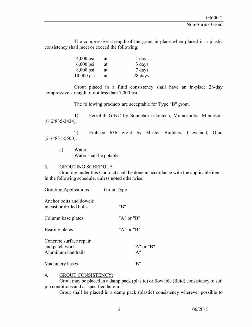
03600-2 Non-Shrink Grout
2 06/2015
The compressive strength of the grout in-place when placed in a plastic
consistency shall meet or exceed the following:
4,000 psi at 1 day 6,000 psi at 3 days 8,000 psi at 7 days 10,000 psi at 28 days
Grout placed in a fluid consistency shall have an in-place 28-day
compressive strength of not less than 7,000 psi.
The following products are acceptable for Type "B" grout.
1) Ferrolith G-NC by Sonneborn-Contech, Minneapolis, Minnesota (612/835-3434).
2) Embeco 636 grout by Master Builders, Cleveland, Ohio (216/831-5500).
c) Water. Water shall be potable.
3. GROUTING SCHEDULE:
Grouting under this Contract shall be done in accordance with the applicable items in the following schedule, unless noted otherwise: Grouting Applications Grout Type Anchor bolts and dowels in cast or drilled holes "B" Column base plates "A" or "B" Bearing plates "A" or "B" Concrete surface repair and patch work "A" or "B" Aluminum handrails "A" Machinery bases "B" 4. GROUT CONSISTENCY:
Grout may be placed in a damp pack (plastic) or flowable (fluid) consistency to suit job conditions and as specified herein.
Grout shall be placed in a damp pack (plastic) consistency wherever possible to

03600-3 Non-Shrink Grout
3 06/2015
provide the highest strength grout.
Damp pack (plastic) grout shall be used for vertical surfaces, with holes having at least one surface dimension less than the hole depth and for holes left by removal of fasteners and form ties.
Damp pack (plastic) grout may be used for column base plates, bearing plates, machinery bases and precast concrete elements where either horizontal dimension of the element being grouted is less than 16 inches.
Flowable or fluid grout shall be used for all other applications. 5. SURFACE PREPARATION.
a) General. Concrete surfaces to receive grout shall be rough and reasonably level.
Laitance shall be removed to sound concrete. The surfaces, including bolt holes, shall be saturated with water for 24 hours prior to grouting, unless otherwise recommended by the grouting manufacturer.
Where grout is to be used to repair damaged concrete surfaces, the damaged or honeycombed concrete shall be removed to sound concrete by chipping.
Metal surfaces to receive grout shall be de-rusted, cleaned of oil, grease and other deleterious substances by means of appropriate solvents, wire brushing or a combination of both.
b) Formwork. Forms shall be provided for grout placed at a flowable or fluid consistency. Forms shall be strong, tight and shall be braces so they will not leak or
buckle under the weight of fluid grout. On the placing side, forms shall slant at a 45 degree angle, and grout shall be poured directly on the slanted face. On other sides, the form shall be placed 1/2 inch or more away from base of the bedplate and one inch or more higher than the underside of the plate.
Provide air relief openings to avoid entrapment of air. 6. GROUT PREPARATION, PLACEMENT AND CURING:
Grout shall be mixed to proper consistency, placed and cured as instructed by the grout manufacturer. A paddle type mortar mixer or other suitable mechanical mixer shall be used, unless otherwise allowed.
Any nearby vibrating machinery or equipment should be shut down to avoid disturbing the bonding or initial set of freshly placed grout.
Mixing water temperature shall not be less than 40 degrees F nor exceed 80 degrees

03600-4 Non-Shrink Grout
4 06/2015
F, unless more stringent conditions are required by the grout manufacturer.
Grout shall be placed at a temperature of 65 to 75 degrees and maintained at this temperature range for 24 hours, and above 40 degrees F thereafter until the grout strength exceeds 4,000 psi.
Grout used for concrete surface repair and patchwork shall be applied to a small area and allowed to cure to determine color compatibility.

09902-1
SECTION 09902 COATINGS & FINISHES
PART 1 PAINTING
1.01 GENERAL
The items covered by this Section include cleaning, abrasive blast cleaning and painting of all interior and exterior steel surfaces. Work also includes disinfection of the tank after coating.
1.02 REFERENCE STANDARDS
Work performed and materials used must comply with the latest revisions of the following standards:
A. AWWA (American Water Works Association) D100-17 Standard for Welded
Steel Tanks for Water Storage, latest revision. B. AWWA D102-17 Standard for Painting Steel Water Storage Tanks. C. AWWA C652 Standard for Disinfection of Water Storage Facilities. D. NSF (National Sanitation Foundation) 61 - Materials in contact with Potable
Water. E. Steel Structures Painting Council Manual - Volume 1 - Good Painting Practice, F. Steel Structures Painting Council Manual - Volume 2 - Systems and
Specifications.
1.03 SUBMITTALS
Before beginning of the work, the contractor shall provide the Engineer with the following information:
A. Name of the protective coating supplier and manufacturers data for the paint
systems being used. B. A listing of the specific products proposed for use including but not limited to
abrasive materials, paint, solvents, thinners, etc. C. Product data sheets for each of the proposed materials. D. Samples of the color specified for owner approval. E. The successful bidder shall be prepared to submit upon demand a list of at least five
tanks of comparable size, design and use in which the coating system which he proposes to use has been successfully installed by him and has given satisfactory service.
1.04 QUALITY CONTROL
A. Only paint and painting materials as specified or approved shall be used.

09902-2
B. Paint shall be delivered in the original factory sealed, labeled, and unbroken containers bearing the designated name, specification number, color, directions for use, manufacturer and date of manufacture.
C. All manufacturers’ instructions shall be carefully followed in the preparation, application, curing or drying and handling of the paint.
D. All prime, intermediate and finish coating materials shall be applied in different color shades.
E. Paint shall be stored in a location that is protected from the elements, well ventilated and free from excessive heat or open flame sources. No other inflammable materials shall be stored in this area. Proper fire prevention practices shall be exercised.
F. The contractor shall record environmental conditions, at the beginning of each daily operation, thirty minutes before painting beings and every hour during painting operations, on the attached Environmental Conditions Report.
G Painting shall be performed by skilled painters using the materials and methods specified.
H. Paint cans shall be subject to inspection by the Engineer. I. All coatings must be acceptable to the Georgia Department of Natural Resources.
1.05 HEALTH AND SAFETY
The Contractor shall comply with all regulations as established by the Occupational Safety and Health Act and other government authorities. Up to date Material Safety Data Sheets shall be available on site for all products used. Workers shall wear proper protection devices. Where ventilation is used, all equipment shall be explosion proof. Temporary ladders and scaffolding systems shall conform to applicable safety requirements. It shall be the responsibility of the Contractor to adequately protect, shield or cover all structure, machinery, equipment and openings as required to prevent damage or contamination from the work procedures. The work area shall always be kept clean, consistent with the type of work being performed.
1.06 TESTING
Dry Coating thickness measurements shall be made using a Magnetic Gauge. Tolerances to be in accordance with SSPC-PA 2 Measurement of Dry Coating Thickness with Magnetic Gauges. Additional coats shall be applied as required to obtain the specified thickness. The Contractor will be required to perform Holiday Testing as soon as the work is sufficiently cured according to the manufacturer’s recommendations. All pinholes and other deficiencies will be repaired. Contractor shall provide an approved paint film thickness gauge and check film thickness as required by the authorized representative of the tank owner.

09902-3
1.07 SITE CONDITIONS
The Contractor shall ensure that surface and ambient conditions are in accordance with the manufacturer’s instructions immediately prior to and during application and for the period of curing. No paint shall be applied when the surrounding air temperature as measured in the shade is above or below the manufacturer’s specifications. No paint shall be applied when the temperature of the surface to be painted is below manufacturer’s recommended application temperature. Painting shall not be applied to wet or damp surfaces or when the ambient temperature is less than 5 degrees above the dew point.
PART 2 PRODUCTS 2.01 ACCEPTABLE MANUFACTURERS
A. Specified products are those manufactured by TNEMEC Co. are specified as the standard of quality required for use on this project.
B. Equivalent products by Carboline or PPG are acceptable, providing they meet or exceed all performance criteria of the specified materials. No products shall be considered that would decrease film thicknesses or offer a change in generic type of coasting specified.
C. Before submitting a bid based on a coating other than the specified, submit to the Engineer for approval at least 10 days prior to the bid date, all pertinent data on the substitution coating including performance data as determined by an independent testing laboratory. Failure to submit such data for approval 10 days prior to the Bid date may result in rejection of the substitution coating system.
D. Products for each specified function and system shall be of a single manufacturer. 2.02 MATERIALS
A. Zinc-rich urethane primer: TNEMEC Series 94 OR EQUAL B. Polyamide epoxy potable water intermediate and finish: TNEMEC Series FC20-
1255 and Series 141 OR EQUAL C. Solvent less epoxy filler and surfacer for pit repairs: TNEMEC Series 215 OR
EQUAL D. Urethane exterior intermediate coating: TNEMEC Series 1075-Color OR
EQUAL E. Fluoropolymer Polyurethane Topcoat: TNEMEC Series 700-Color OR EQUAL F. Flexible urethane caulking: SIKA-FLEX 1A or equal.
2.03 MATERIAL PREPARATION
A. Mix and thin materials according to manufacturer's latest printed instructions. B. Do not use materials beyond manufacturer's recommended shelf life. C. Do not use mixed materials beyond manufacturer's recommended pot life.

09902-4
PART 3 SURFACE PREPARATION
3.01 INTERIOR SURFACE PREPARATION
Remove all oil or greasy contamination from the surface prior to blast cleaning. All interior wet surfaces shall be abrasive blast cleaned to a SSPC SP-10 Near White Finish with a surface profile compatible with the paint manufacturer’s recommendations. Interior dry surfaces shall be cleaned to a SSPC SP-6 Commercial Finish. Immediately after blasting and before any rusting occurs, apply one coat of shop primer as per the interior paint specifications.
3.02 EXTERIOR SURFACE PREPARATION
Remove all oil or greasy contamination from the surface prior to blast cleaning. All surfaces shall be abrasive blast cleaned to a SSPC SP-6 Commercial Finish with a surface profile compatible with the paint manufacturer’s recommendations. Immediately after blasting and before any rusting occurs, apply one coat of shop primer as per the exterior paint specifications.
3.03 FIELD SURFACE PREPARATION
After erection and prior to field touch up, all surfaces shall be cleaned to remove all surface contamination including oil, grease, dust, dirt and foreign matter. Weld slag, weld spatter and other sharp or rough projections shall be removed. All rusted, abraded and unpainted areas on the interior wet area shall be abrasive blast cleaned to a near white finish in accordance with SSPC SP-10. All other rusted, abraded and unpainted areas shall be either abrasive blast or mechanically cleaned to a SSPC SP-6 Commercial Finish.
3.04 PAINT APPLICATION
Coating materials to be applied in successive coats as specified by the manufacturer to attain the required dry film thickness for each system. Coatings to be applied without sags, foreign materials contamination or blemishes. The paint coatings shall be Tnemec or an approved equal. The contractor shall submit the manufacturer's coating system to the engineer for approval.
All paints shall be stirred and mixed until there is a complete blending of the entire
contents of the container before use and stirring shall be repeated as required to prevent separation of the pigment vehicle. All surfaces to be painted shall be prepared in a proper manner with the objective of obtaining a clean, smooth, dry surface free from dirt, grease, mill scale, rust, cracks, ridges, holes, dust, etc.
All painting will be performed in a workmanlike manner, by workmen experienced
in their craft, and in strict accordance with the directions of the paint manufacturer.

09902-5
The paint shall be applied at the approximate rate specified by the manufacturer for the dry coating thickness indicated for each coat. The method of application (spray, brush, roller) recommended by the paint manufacturer must be followed. Paint must be evenly applied no matter what method of application is used. Where thinning is necessary and permitted, only the products and quantities recommended by the manufacturer shall be used.
Painters shall protect, by covering, surfaces that might otherwise be damaged by
drippings or splashing of paint.
All painting shall be done under suitable conditions by skilled painters. Paint shall be applied only when the air temperature is at or above 40oF. No paint shall be applied during wet or foggy weather, or upon damp surfaces of metal coated by frost.
Where the required minimum dry film thickness is not achieved by application of the number of coats specified, additional coats will be required at the contractor's expense to achieve the minimum dry film thickness specified.
3.05 SHOP PRIME
Apply prime coat after blast cleaning and prior to flash rusting. If rust appears as a result of delay in primer application the surface shall be re-blasted to specified surface preparation. A six-inch strip of blasted uncoated bare steel shall be left between the primed area and the edge of the steel plate.
PART 4 COATING SYSTEMS
4.01 A INTERIOR COATING (WET AREA)
A. Interior Surface Preparation: Remove all visible oil, grease, soil, dirt and other
soluble contaminants in accordance with SSPC-SP1. All interior surfaces shall be abrasive blast cleaned by Near White Blast Cleaning in accordance with the recommended methods outlined in the Society for Protective Coatings’ Specification SSPC-SP10 (NACE No. 2). A surface profile of 1.5 to 2.5 mils is required.
B. Shop Prime Coat: Immediately after blasting and before any rusting occurs (12 hours maximum) apply TNEMEC Series 94-H2O OR EQUAL at a dry film thickness of 2.5 to 3.5 mils to all interior steel surfaces
C. Field Stripe Coat: Apply one complete coat of TNEMEC Series FC20-1255 Beige OR EQUAL to all weld seams at a dry film thickness of 2.0 to 3.0 mils.
D. Field Finish Coat: Apply one complete coat of TNEMEC Series 141-1253 Gray OR EQUAL at a dry film thickness of 10.0 to 14.0 mils.
E. Seams: All roof lap seams, and any other gapped or skip weld seams shall be caulked after priming with Sika-Flex 1A

09902-6
F. Minimum dry film thickness is 12.5 mils
4.01 B INTERIOR COATING (DRY AREA) G. Interior Surface Preparation: All interior dry steel surfaces shall be abrasive
blast cleaned by Commercial Blast Cleaning in accordance with the recommended methods outlined in the Society for Protective Coatings’ Specification SSPC-SP6
H. Shop Prime Coat: Immediately after blasting and before any rusting occurs (12 hours maximum) apply TNEMEC Series 94-H2O OR EQUAL at a dry film thickness of 2.5 to 3.5 mils to all interior steel surfaces
I. Field Finish Coat: Apply one complete coat of TNEMEC Series 141-1253 Gray OR EQUAL at a dry film thickness of 8.0 to 12.0 mils.
J. Minimum dry film thickness is 10.5 mils
4.02 EXTERIOR COATING A. Exterior Surface Preparation: All exterior steel surfaces shall be abrasive blast
cleaned by Commercial Blast Cleaning in accordance with the recommended methods outlined in the Society for Protective Coatings’ Specification SSPC-SP6
B. Shop Prime Coat: Immediately after blasting and before any rusting occurs (8 hours minimum), apply one coat of TNEMEC Series 94-H2O OR EQUAL to all bare steel surfaces at a dry film thickness of 2.5 to 3.5 mils.
C. Field Intermediate Coat: Apply one coat of TNEMEC Series 1075 OR EQUAL-Color * at a dry film thickness of 2.0 to 3.0 mils. Color shall be lighter than the finish color. Color shall be: Tnemec Cloud 57BR.
D. Field Finish Coat and Graphics: Apply TNEMEC Series 700-Color * OR EQUAL at a dry film thickness of 2.0 to 3.0 mils. Color shall be specified by the Engineer prior to start of construction.
E. Color: The exterior topcoat color chosen by MWA shall be: Tnemec White 00WH.
K. Minimum dry film thickness is 6.5 mils
*NOTE: TNEMEC Series 44-710 URETHANE ACCELERATOR OR EQUAL may be used when the air, material or surface temperature is anticipated to be between 35ºF and 55ºF during application and/or curing.
4.04 LOGO
A. Logo shall include all costs associated with the placement of on two sides of the
tank’s bowl assembly in a color to be selected by the Owner prior to construction. The MWA logo is being updated during Spring 2020. Final logo details will be prepared prior to time of painting. Final logo will be similar to, but not identical to, the existing logo shown below:

09902-7
4.05 VENTILATION
The contractor shall provide ventilation while cleaning and painting the interior surfaces of the tank which shall be adequate to remove fumes sufficiently to prevent the injury of any workman and to eliminate the possibility of accumulation of volatile gases within the tank.
PART 5 CLEANLINESS 5.01 GENERAL The contractor and all workmen employed by him, shall conduct all operations in
a clean and sanitary manner. No nuisance of any kind shall be committed in the tank. The workmen shall either use proper waste receptacles or leave the tank whenever necessity arises.
No one shall work in the tank if he has been under a physician's care within a seven (7) day period prior to entering or working in the tank. No person shall be allowed to work in the tank who has an abnormal temperature or gives evidence of illness. The owner shall reserve the right to have its own agent to judge the physical fitness or unfitness of any person to enter or work in said tank. No deviation from the requirement will be permitted.
After completion of painting, remove all traces of splashed materials, paint droppings, and spots from finished and adjacent surfaces.
PART 6 DISINFECTION & TESTING
6.01 GENERAL
After the storage tank has thoroughly cured, water and chlorine shall be added to the storage facility in amounts such that initially the solution will contain 50-mg/L available chlorine and will fill approximately 5 percent of the total storage volume. This solution shall be held in the storage facility for a period of not less than 6 h. The storage facility shall then be filled to the overflow level by flowing potable water into the highly chlorinated water. It shall be held full for a period of not less than 24 h. All highly chlorinated water shall then be purged from the drain piping.

09902-8
Following this procedure, and subject to satisfactory bacteriological testing and acceptable aesthetic quality, the remaining water may be delivered to the distribution system.
Chlorine shall be added to the storage facility by the method described in AWWA Section 4.1.1, 4.1.2 or 4.1.3. The actual volume of the 50-mg/L chlorine solution shall be such that, after the solution is mixed with filling water and the storage facility is held full for 24 h, there will be a free chlorine residual of not less than 2 mg/L. The tank shall be filled with clean water furnished by the owner, one time only. Any additional filling of the tank due to contractor’s inability to obtain enough test results, shall be paid for at the Contractors expense.
6.02 BACTERIOLOGICAL TESTING
After the chlorination procedure is completed, and before the storage facility is
placed in service, water from the full facility shall be sampled and tested for coliform organisms in accordance with the latest edition of Standard Methods for the Examination of Water and Wastewater. The testing method used shall be either the multiple-tube fermentation technique or the membrane-filter technique.
The water in the full facility should also be tested to assure that no offensive odor
exists due to chlorine reactions or excess chlorine residual.
If the test for coliform organisms is negative, then the storage facility may be placed in service. If the test shows the presence of coliform bacteria, the situation shall be evaluated by a qualified engineer. In any event, repeat samples shall be taken until two consecutive samples are negative, or the storage facility shall again be subjected to disinfection.
The samples shall be taken from a sample tap on the outlet piping from the storage
facility or from a sample tap connected directly to the storage facility. In either case, the operation shall be such as to ensure that the sample collected is from water that has been in the storage facility.
During the disinfection operation and the required sampling of water from the storage facility, it is recommended that samples be taken from water inflowing to the storage facility to determine if coliforms are present in the typical potable water source. Samples shall be sent to the Environmental Protection Division, State Water Laboratory, (47 Trinity Avenue, S.W., Atlanta, Georgia 30334) for bacteriological analysis. If the results are unsatisfactory, the sterilization procedure must be repeated, and additional samples taken until satisfactory results are obtained.

09902-9
6.03 WARRANTY A 15-year gloss and color retention exterior warranty, with warranty jobsite coupon
panels, will be issued by the material manufacture to the owner within 30 days after the completion of the job.

(This page left blank intentionally.)

10400-1
Identifying Devices
10400-1 4040-070/12.09
SECTION 10400
SECTION 10400 IDENTIFYING DEVICES 1. SCOPE: Under this section shall be included the furnishing and installation of various signs throughout, as shown and specified herein. 2. SHOP DRAWINGS: Shop drawings shall be submitted. See the General and Special Conditions. 3. MATERIALS: a) Plaque. Plaque shall be cast-bronze and as shown. Shop drawings shall show full size details of border and lettering. Plaque shall be 20 inches by 30 inches with flat band bevel border and pebble texture background and shall contain about 500 characters in various sizes. Lettering shall be as made by Metal Arts Division of L & H Manufacturing Company, Mandan, North Dakota or Andco Industries Corporation, Greensboro, North Carolina or equal. 4. INSTALLATION: Install this work straight and plumb, securely anchored in place. Use theft-proof fasteners where fasteners will be exposed. Mounting heights shall be as shown and/or as directed.

(This page left blank intentionally.)

SCADA System and Instrumentation
13394-1
PART 1 GENERAL 1.01 Scope
A. The CONTRACTOR shall engage the services of the approved Instrumentation and Control System Integrator to provide field instrumentation, radio telemetry hardware, and SCADA additions and modifications to Macon Water Authority’s existing Supervisory Control and Data Acquisition (SCADA) human-machine interface (HMI) software as required to monitor and control the new Atlantic Mill Elevated Tank.
B. The new Atlantic Mill Elevated Water Tank will be designed to support dual,
independent monitoring. One independent radio connection will be established between the Finished Water pump Station located at the Amerson Water Treatment Plant and the new Atlantic Mill Elevated Tank. The second radio connection will be established between the new Atlantic Mill Elevated Tank and Macon Water Authority’s existing radio-based telemetry system.
C. The Instrumentation and Control System Integrator shall perform programming as
required to integrate real-time and historical data into the existing Wonderware Human-Machine Interface (HMI) software package and to perform the required programming modifications for the new and existing programmable logic controllers (PLCs) as required to incorporate new Atlantic Mills Elevated Tank into the SCADA system logic.
The Instrumentation and Control System Integrator shall provide a new PLC-based Remote Telemetry Unit (RTU) incorporating an Allen-Bradley MicroLogix PLC, 4RF radio, high gain Yagi antenna, 7/8” coaxial cable, 1.02 Submittals
A. Submit detailed product data for review by the Owner and Engineer for the following major system components: 1. New PLC-based Remote Telemetry Unit (RTU) for the Atlantic Mills
Elevated Tank; 2. Yagi Antenna with 7/8” coaxial cable, connectors, grounding kits and RF
surge protector hardware, and other ancillary components as required; 3. Proposed modifications to SCADA System Software; 4. Proposed modifications to existing polling software; 5. Revised Telemetry System Diagram to depict the introduction of the new
Atlantic Mills Elevated Tank into the existing radio telemetry system. 6. Field Instrument Submittals for the following devices:
a. Tank Level Transmitter No. 1 b. System Pressure Transmitter and Tank Level Transmitter No. 2 c. Ultrasonic Level Transducer and Transmitter to monitor level of the
Retention Pond.

SCADA System and Instrumentation
13394-2
7. Intrusion monitoring switches for the Tank Entrance Door and the Tank Rollup Door.
B. Contractor shall provide shop drawings for all control systems which identify all
components and shall include a complete system diagram and electrical Elementaries showing all interconnections, including wiring numbers and terminal numbers for all equipment. The Instrumentation and Control System Integrator shall coordinate final drawings with equipment actually being provided by the Contractor for this project. Contractor shall provide record drawings (reproducible and three copies) indicating all field changes.
1.03 Major SCADA Equipment for Rush Creek Water Treatment Plant
A. The table below lists the major components to be supplied by the Instrumentation and Control System Integrator under this section of the specifications.
Device Tag Description Comments LIT-1 Level Indicator Transmitter Atlantic Tank Level LIT-2 Level Indicator Transmitter System Pressure and Atlantic
Tank Level LE/LIT-3 Ultrasonic Level Indicating Transmitter
and Transducer Retention Pond Level
RTU-AMT PLC-based Remote Telemetry Unit with Allen-Bradley ConpactLogix PLC, two (2) radios, battery backup system, etc.
Radios to operate in the 900 MHz frequency range. Enclosure to be NEMA 4X, #304 stainless steel.
ANT-1 12 dB Yagi Antenna for communications to the Amerson Finished Water Pump Station
Include 7/8” coaxial cable, RF surge protector and associated installation hardware.
ANT-2 12 dB Yagi Antenna for communications to the Amerson Finished Water Pump Station
Include 7/8” coaxial cable, RF surge protector and associated installation hardware.
PART 2 PRODUCTS 2.01 Acceptable Manufacturers
A. The telemetry system and all instrumentation and controls shall be furnished and installed under the supervision of a single Instrumentation and Control System Integrator who is regularly engaged in the design and installation of SCADA and instrumentation systems for the municipal water and wastewater industry.

SCADA System and Instrumentation
13394-3
B. The Instrumentation and Control System Integrator shall be MR Systems, Inc. of Norcross, Georgia.
2.02 Remote Telemetry Unit Construction
A. It is the intent of these specifications to establish the minimum requirements for the new Remote Telemetry Unit (RTU) to be installed inside the Atlantic Mills Elevated Tank.
B. All SCADA subpanels supplied for this project shall be constructed to meet UL
508 standards.
C. RTU Enclosure and PLC Make and Model 1. The new remote telemetry unit shall be housed in a NEMA 4X, #304
stainless steel enclosure with carbon steel subpanel. The enclosure shall be manufactured by Hoffman or Saginaw Control & Engineering. The approximate dimensions of the enclosure shall be 36” H x 30” W x 12” D or 48” H x 36” W x 12” D.
2. The programmable logic controller shall be an Allen-Bradley CompactLogix configured using the following components. a. Allen-Bradley CompactLogix 5380 #5069-L320ER, 2MB, supports up
to 16 modules. Include one (1) #5069-RTB64-SCREW Screw Terminal.
b. Allen-Bradley CompactLogix #1784-SD2, 2 GB, Memory Module: Provide one (1) for use and two (2) as spare parts.
c. Allen-Bradley Compact I/O #5069-IB16, 16-Channel, 24Vdc (Sink) Digital Input Module. Include one (1) #5069-RTB18-SCREW Screw Terminal.
e. Allen-Bradley Compact I/O #5069-OB16, 16-Channel, 24Vdc Source, Digital Output Module. Include one (1) #5069-RTB18-SCREW Screw Terminal.
f. Allen-Bradley Compact I/O #5069-IF8, 8-Channel Voltage/Current Analog Input Module, Non-Isolated. Include one (1) #5069-RTB18-SCREW Screw Terminal.
g. Allen-Bradley Compact I/O #5069-OF8, 8-Channel Voltage/Current Analog Output Module, Non-Isolated. Include one (1) #5069-RTB18-SCREW Screw Terminal.
D. SCADA Subpanel Wiring and General Construction
1. All components and equipment integral to the SCADA Panel shall be suitable for
operation on 120 Volt, 60 Hertz, single-phase, AC power or 24 Volt DC power.

SCADA System and Instrumentation
13394-4
2. All field wiring terminations shall be made to terminal strips capable of accommodating up to #12 AWG wire. Terminal strips shall be mounted using DIN rails. Terminal strips shall be as manufactured by Weidmuller, Phoenix, Square D, Allen-Bradley, or approved equal.
3. All analog inputs and outputs, including all spare analog inputs and outputs, shall
be protected from surges using three separate levels of surge/transient suppression. The first level of protection shall be via a 1/4 Amp 3AG size fast acting fuse. Secondary and tertiary protection shall be fulfilled using combination gas discharge and metallic oxide varistor (MOV) surge protection with current limiting resistors. Terminals shall be installed to allow each of the four analog inputs to be configured for 2-wire or 4-wire process transmitters and to produce either 4 to 20 mA or 1 to 5 VDC outputs to the Motorola PLC and any future display or signal conversion devices. Terminals shall be installed adjacent to each spare analog surge protector to provide 24 VDC for connections of future 2-wire transmitters. Spare analog inputs and outputs shall be wired to analog surge protection, fuses, etc. and shall be ready to accommodate future field signals. Analog surge protectors shall be the Kamikaze II as developed by Phoenix Contact and MR Systems, Inc. and manufactured by Phoenix Contact.
4. All digital inputs, including spare digital inputs, shall be isolated via indicating electro-mechanical interposing relays using LED indicators.
5. Minimum contact rating for relays shall be 6 Amps at 115VAC, minimum. Digital
inputs shall be connected to field wiring via DIN rail mounted terminal strips. A 2-Amp 3AG size fuse shall protect each group of digital inputs. Spare digital inputs shall be fully wired complete with relay isolation and terminal strips to accommodate future field signals.
6. All digital outputs, including spare digital outputs, shall be isolated from field
wiring through terminal strips and indicating electro-mechanical relays with contact ratings of 10 Amps at 250VAC, minimum with LED indicators. Spare digital outputs shall be fully wired complete with relay isolation and terminal strips to accommodate future field signals.
7. Separate DC power supplies shall be provided for the PLC, analog I/O field
supply, and digital I/O field supply. All DC power supplies shall be protected via indicating 3AG size fast acting fuses. Indicating fuse holders shall be DIN rail mounted.
8. An LED utility light shall be mounted in the top the SCADA Closet. The light
shall be wired to a 2-pole limit switch that shall be mounted on the door of the enclosure. When the door is opened, the light will automatically be turned on. When the door is closed, the light will automatically be turned off.

SCADA System and Instrumentation
13394-5
9. A battery backup charger/power supply system with two (2) 9-amp-hour batteries
shall be provided to supply DC power to the RTU for a minimum of eight (8) hours after an AC power failure.
10. A two (2) circuit breakers shall be provided integral to the SCADA Closet. One
shall provide AC power to the battery backup system and the other shall power a 10-amp Utility Outlet to support test equipment or a notebook computer.
11. An AC power surge protector shall be installed integral to the PLC or RTU Panel
to provide transient and surge protection for incoming AC power. A separate 20-amp GFI duplex utility outlet shall be protected by the surge protector and shall be used only to power the UPS system.
12. For 120 VAC power supplied from a foreign source, provide an engraved
nameplate (white letters, red background) to read “WARNING – This panel energized by foreign control power sources. Equipment will be live with panel disconnect in either on or off position.”
13. Radio Communications Work to be performed at the Atlantic Mills Elevated Tank
A. One (1) 4RF Aprisa SRi radio shall be supplied for communications between the Atlantic Mill Elevated Tank and the Finished Water Pump Station at the Amerson Water Treatment Plant. This radio shall be mounted in the new Atlantic Mills Tank RTU enclosure.
B. This radio link shall operate in the unlicensed spread spectrum frequency range
between 902 MHz and 928 MHz.
C. Supply one (1) 14 dB Yagi antenna (suitable for 902 MHz to 960 MHz frequency range), the required length of 7/8” coaxial cable, RF surge protector in polycarbonate outdoor enclosure, and all other required appurtenances require for successful operation of this radio link.
D. Please note that a minimum of 10 feet of vertical separation must be maintained
between he 14 dB Yagi mounted atop the Atlantic Mills Elevated Tank and any other antenna mounted atop the Atlantic Mill Elevated Tank.
14. Radio Communications Work to be performed at the Amerson WTP
A. One (1) 4RF Aprisa SRi radio shall be supplied for communications between the Atlantic Mill Elevated Tank and the Finished Water Pump Station at the Amerson Water Treatment Plant. This new 4RF Aprisa SR radio shall be mounted in existing LCP-G which will contain an Allen-Bradley CompactLogix PLC. The existing PLC will be programmed to perform polling of the Atlantic Mill Elevated Tank PLC-based RTU.

SCADA System and Instrumentation
13394-6
B. The Instrumentation and Control System Integrator shall provide and install a 40 ft.
wooden pole adjacent to the Finished Water Pump Station. A 14 dB Yagi antenna (suitable for 902 MHz to 960 MHz frequency range), 7/8” coaxial cable, RF surge protector in polycarbonate outdoor enclosure and all other required appurtenances require for successful operation of this radio link.
2.03 Human-Machine Interface Software – Amerson WTP System SCADA System
A. The Instrumentation and Control System Integrator shall perform programming modifications to the existing WTP Wonderware SCADA/HMI system located at the Amerson Water Treatment Plant to establish communications with the new Atlantic Mills Elevated Tank remote telemetry unit.
B. All I/O available on the Atlantic Mills Tank RTU shall be brought into the SCADA
system and displayed in accordance with the Owner’s directions.
2.04 Human-Machine Interface Software – Radio Telemetry System A. The Instrumentation and Control System Integrator shall perform programming
modifications to the existing Telemetry System Wonderware SCADA/HMI system located at the Amerson Water Treatment Plant to establish communications with the new Atlantic Mills Elevated Tank remote telemetry unit.
B. All I/O available on the Atlantic Mills Tank RTU shall be brought into the
Telemetry System SCADA system software shall be and displayed in accordance with the Owner’s directions.
PART 3 EXECUTION 3.01 Installation
A. All data from the new SCADA system for WTP No. 2 shall be interfaced with the existing SCADA system.
B. Final terminations of all signal and power wiring to the SCADA Subpanel for the
SCADA Closet shall be performed by the Instrumentation and Control System Integrator.
3.02 Training
A. The Control System Integrator shall provide one (1) 8-hour day of onsite training to cover operation of the new SCADA application.
B. The Control System Integrator shall provide one (1) 8-hour day of onsite training to
cover preventive maintenance and instrument calibration for the new instruments.

SCADA System and Instrumentation
13394-7
I/O Signals Atlantic Mills Elevated Tank RTU DI-1 Man-Door Open/Closed Status DI-2 Roll-up Door Open/Closed Status DI-3 Spare DI Point – Wired to Field Terminals via Interposing Relay DI-4 Spare DI Point – Wired to Field Terminals via Interposing Relay DI-5 Spare DI Point – Wired to Field Terminals via Interposing Relay DI-6 Spare DI Point – Wired to Field Terminals via Interposing Relay DI-7 Spare DI Point – Wired to Field Terminals via Interposing Relay DI-8 Spare DI Point – Wired to Field Terminals via Interposing Relay DI-9 Spare DI Point – Wired to Field Terminals via Interposing Relay DI-10 Spare DI Point – Wired to Field Terminals via Interposing Relay DI-11 Spare DI Point – Not Wired DI-12 Spare DI Point – Not Wired DI-13 Spare DI Point – Not Wired DI-14 Spare DI Point – Not Wired DI-15 AC Power – Failure DI-16 Battery Backup System – Fault DO-1 Spare DO Point – Wired to Field Terminals via Control Relays DO-2 Spare DO Point – Wired to Field Terminals via Control Relays DO-3 Spare DO Point – Wired to Field Terminals via Control Relays DO-4 Spare DO Point – Wired to Field Terminals via Control Relays DO-5 Spare DO Point – Wired to Field Terminals via Control Relays DO-6 Spare DO Point – Wired to Field Terminals via Control Relays DO-7 Spare DO Point – Not Wired DO-8 Spare DO Point – Not Wired DO-9 Spare DO Point – Not Wired DO-10 Spare DO Point – Not Wired DO-11 Spare DO Point – Not Wired DO-12 Spare DO Point – Not Wired AI-1 Elevated Tank Level No. 1 AI-2 Elevated Tank Level No. 2 AI-3 Retention Pond Level AI-4 Spare Analog Inputs wired to Kamikaze Analog Surge Protector AI-5 Spare Analog Inputs wired to Kamikaze Analog Surge Protector AI-6 Spare Analog Inputs wired to Kamikaze Analog Surge Protector AI-7 Spare Analog Inputs wired to Kamikaze Analog Surge Protector AI-8 Spare Analog Inputs wired to Kamikaze Analog Surge Protector AO-1 Spare AO Points – Wired to Analog Surge Protector AO-2 Spare AO Points – Wired to Analog Surge Protector

SCADA System and Instrumentation
13394-8
AO-3 Spare AO Points – Wired to Analog Surge Protector AO-4 Spare AO Points – Wired to Analog Surge Protector AO-5 Spare AO Points – Not Wired AO-6 Spare AO Points – Not Wired AO-7 Spare AO Points – Not Wired AO-8 Spare AO Points – Not Wired
END OF SECTION

15294-1
SECTION 15294 COMPOSITE ELEVATED WATER STORAGE TANK
(3,000,000 GALLON) PART 1 – GENERAL
1.1 Summary
A. Scope of Work
The work to be performed under these specifications includes furnishing all labor, materials, tools and equipment necessary to design, fabricate, construct, inspect and test a welded steel elevated water storage tank supported on a concrete support structure, including the foundation and accessories as shown on the drawings and specified herein.
The work shall also include all labor, materials and equipment necessary to clean, paint and disinfect the water storage tank as specified herein.
B. Related Work
The work shall also include all labor, materials and equipment necessary to construct the site improvements and site piping as shown on the drawings.
C. Description
The tank and support structure shall be the composite elevated tank style as designed and constructed by the tank manufacturer. The tank shall be of all welded steel design and have a dome roof, straight sides and a cone bottom. The support structure shall be of concrete design. The concrete support structure shall be configured so that a concrete tank floor with a steel liner plate supports the water inside the steel reservoir. Suspended steel tank floor configurations are not allowed.
D. Related Documents
Drawings and the general provisions of this document, including General Conditions, Supplemental Conditions, Special Provisions and other Division 1 Sections apply to work in this section.
E. Related Sections
Section 03300 Concrete Section 09902 Coatings and Finishes Division 16 Electrical
Permit FAA Determination of No Hazard to Air Navigation (Aeronautical Study No. 2019-ASO-31335-OE)

15294-2
1.2 Quality Assurance
A. Contractor Requirements
The composite elevated tank and foundation design, concrete support structure construction and welded steel tank fabrication and construction shall be performed by the Contractor’s own direct hire employees and shall not be subcontracted in any way. The tank’s foundation may be supervised and installed by the Contractor or a qualified local foundation subcontractor.
The contractor shall directly employ a full time professional engineer with a minimum five years cumulative experience in the design and construction of Composite elevated tanks. The engineer shall be registered in the State the work is being performed and shall be in responsible engineering charge of the work. A qualified supervisor directly employed by the manufacturer shall be on site at all times during construction of the foundation, support structure and steel tank.
B. Regulatory Requirements
The specifications, codes and standards referenced in paragraph 1.4 shall govern the work with regard to materials, design, construction, inspection and testing to the extent specified. Personnel safety equipment shall be provided in accordance with OSHA requirements and manufacturers documentation.
1.3 Qualification of Contractor
A. Experience Requirements of Tank Contractor
The work described in this section shall be performed by a company that specializes in the design and construction of composite elevated tanks. The tank contractor shall have the following qualifications: 1. A minimum of five years experience in composite tank design and construction.
2. The design, construction and commissioning of a minimum three Composite
elevated tanks of equal or greater capacity in successful service for 2 years. These tanks shall be of the same design and constructed using forming systems as detailed by this specification.

15294-3
B. Acceptability of Tank Contractors
The Engineer and / or Owner shall be the sole and final judge as to the acceptability of a tank contractor’s qualifications.
1.4 Standards, Codes, and Guides
The latest version of the following Specifications, Codes and Standards are referenced in this section.
AWWA D100 Welded Steel Tanks for Water Storage AWWA D102 Coating Steel Water Storage Tanks AWWA D107 Composite Elevated Tanks for Water Storage ACI 117 Standard Tolerances for Concrete Construction and Materials ACI 301 Standard Specifications for Structural Concrete ACI 304 Guide for Measuring, Mixing, Transporting and Placing Concrete ACI 305 Hot Weather Concreting ACI 306 Cold Weather Concreting ACI 318 Building Code Requirements for Structural Concrete ACI 347 Guide to Formwork for Concrete AISC S335 Specification for Structural Steel Buildings ANSI B16.5 Pipe Flanges and Flanged Fittings ANSI ASCE 7 Minimum Design Loads for Buildings and Other Structures API 650 Welded Steel Tanks for Oil Storage ASTM A 123 Zinc Coatings on Iron and Steel Products ASTM A 240 Stainless Steel Plate, Sheet and Strip for Pressure Vessels ASTM A 285 Pressure Vessel Plates, Carbon Steel ASTM A 774 Welded Stainless Steel Fittings ASTM A 778 Welded Stainless Steel Tubular Products AWWA C652 Disinfection of Water Storage Facilities FAA 70/7460-1H Obstruction Marking and Lighting NACE RP0178 NFPA NEC National Electric Code NFPA 780 Standard for the Installation of Lightning Protection Systems NSF 61 Standard for Drinking Water System Components OSHA 29 CFR Part 1926 Safety and Health Regulations for Construction SSPC-PA1 Paint Application Specification SSPC VIS-89 Visual Standard for Abrasive Blast Cleaned Steel

15294-4
1.5 Submittals
A. Submit with Bid
Each bidder shall provide a list of at least ten projects stating location, completion date, contact names and telephone numbers.
A preliminary section view drawing of the tank proposed for this project. The drawing shall include sufficient detail to illustrate tank geometry, materials of construction, primary dimensions, support wall thickness and pour height, concrete slab thickness, the elevation of low and high-water levels, interior wet, interior dry and exterior paint areas, and other information required to show compliance with the specification. If the proposed design does not comply with the specifications, the bid shall be rejected.
A drawing of the foundation showing preliminary dimensions and approximate quantities of concrete and reinforcing steel shall also be provided with the bid. Failure to provide either of these drawings shall be cause for rejection of the bid.
B. Construction Drawings
A summary of the design for the foundation, support structure and the tank, shall be provided prior to construction. The design summary shall show applicable design and construction standards, materials of construction, design loads and results showing conformance with the specifications. The design shall be sealed by a Professional Engineer licensed in the State of Georgia.
Provide elevation, plan and sectional view drawings of the foundation, support structure, tank and all appurtenant equipment and accessories. Show the location, dimensions, material specifications, and finish requirements. The submission shall be sealed by professional engineer registered in the State of Georgia.
Foundation details shall include excavation, soil protection and backfill.
Reinforced concrete details shall include construction joints, openings and inserts. Reinforcement shall be clearly indicated on the structural drawings and identified by mark numbers that are used on the fabrication schedule. Location, spacing and splice dimensions shall be shown. Placement and fabrication details shall conform to ACI 318.
Steel tank details shall include weld joints and a layout showing all primary and secondary shop and field welds.

15294-5
C. Construction Procedures
Provide procedures for the support structure forming system. Procedures shall include form removal criteria and minimum elapsed time for adjacent concrete placement.
Provide shop and field weld procedures for all structural joints on the steel tank.
D. Design Data
Provide a table showing capacity of the tank in gallons at all levels in one foot increments.
Provide a summary of the design for the foundation, support structure, tank and other components. Include the design basis, loads and load combinations and results.
Provide a finite element analysis that accurately models the intersecting elements of the interface region. The interface region includes those portions of the concrete support structure and steel tank affected by the transfer of forces from the tank cone and the tank floor to the concrete support wall. The analysis shall provide results including the shear, moment, and compression or tension caused by the intersecting elements in the interface region.
E. Product Data
Provide a separate concrete mix design for each concrete compressive strength required or specified.
Provide technical data and color samples of all coating products.
Provide manufacturers descriptive information for appurtenant equipment and accessories that are not detailed on the construction drawings.
F. Reports / Certifications
Provide documentation of all tests, inspections and certifications required by this section.
Welder’s certifications shall be submitted in accordance with AWWA D107.
Provide proof of insurance for Professional Liability with a minimum limit of $2,000,000 each occurrence and aggregate.

15294-6
G. Record Documents
Provide an operating and maintenance manual containing operating instructions, maintenance instructions, as-built construction drawings, cleaning and painting instructions, a gage table and catalog cuts of equipment supplied.
1.6 Delivery, Storage, and Handling
A. Handling and Shipping
The Contractor shall handle materials and fabricated components in a manner that will protect them from damage. Allow painted materials adequate cure time prior to stacking or shipping.
B. Storage and Protection
Protect delivered materials and equipment from damage. Store in well drained areas and provide blocking to minimize contact with the ground.
1.7 Project Conditions
A. Permits and Easements
Permits, licenses, and easements required for permanent structures, changes in existing facilities or advancement of the construction as specified shall be secured and paid for by the Owner prior to the start of construction. These include building permits, airspace authority approval, site access easements, highway crossing permits, etc.
Licenses or permits of a temporary nature required by specific trades shall be the responsibility of the Contractor.
The Owner and/or Engineer have filed Form 7460-1 with the FAA (http://forms.faa.gov/) to determine requirements. The Contractor shall follow all height restrictions, observation marking, obstruction lighting, and other requirements specified in the FAA Aeronautical Study found within the bid documents’ general specifications.
B. Existing Conditions
A geotechnical investigation has been carried out at the site and a report has been incorporated within these specifications. The net allowable bearing pressure of shallow foundations and/or the allowable capacity of deep foundation elements have been defined in this report. The Contractor shall be responsible for securing any further geotechnical information required beyond that provided in this report.

15294-7
C. Access
The Contractor shall provide access from public roads to the tank site unless otherwise specified.
D. Working Conditions
1. Safety and Health - The Contractor shall comply with safe working practices and all health and safety regulations of OSHA, state and local health regulatory agencies and Material Safety Data Sheets (MSDS). Provide protective and lifesaving equipment for persons working at the site.
2. Personnel safety equipment shall be provided in accordance with OSHA requirements and the manufacturers’ documentation. A certified health and safety technician (CHST) will perform spot inspections of the field activities. The safety supervisor is to be a full-time employee of the tank manufacture.
1.8 Sequencing and Scheduling
A. Schedule
The Contractor shall provide a schedule indicating the design, submittals, site work and the major components of construction including foundation, support structure and steel tank. In addition, show tank painting, electrical installation and other significant activities. Update the schedule as required.
B. Certifications
Provide certification from the engineer of record that the elevated tank has been designed in accordance with the requirements of the specification.
Provide certification that testing and inspection requirements of 8.5(B) have been performed and the results comply with the requirements of the specification.
1.9 Guarantees
The Contractor shall guarantee the structure, appurtenant equipment and accessories provided under this section against defective design, workmanship or materials for a period of one year from the date of substantial completion. If notified within this period, the Contractor shall repair any defects at no cost to the Owner. Defects caused by damaging service conditions are not covered.
All guarantees for materials, equipment and accessories provided under this section shall be obtained by the Contractor and submitted.

15294-8
1.10 Professional Liability Insurance
In addition to any requirements specified in the General and/or Supplemental Conditions, the Contractor shall maintain Professional Liability insurance with a minimum limit of $2,000,000 each occurrence and aggregate.
PART 2 – SYSTEM DESCRIPTION
2.1 Tank Description
A. Elevated Tank
The Composite elevated tank shall consist of the following: foundation, reinforced concrete support structure and a welded steel water tank. The support structure shall extend vertically from the foundation as a circular concrete wall. A concrete slab shall be provided as structural support for the steel tank within the perimeter of the wall. A reinforced concrete ring beam shall be provided to connect the steel tank, concrete dome and concrete support wall. The elevated tank shall be in accordance with the shape, dimensions and details required by these specifications and drawings.
B. Operating Parameters
Feature Value Unit Minimum capacity within operating range 3,000,000 gallon Tank Diameter 110 (+/- 5) ft Minimum operating range 45 ft Maximum operating range 50 ft Maximum fill rate (per hydraulic model) 3,500 gpm Maximum fill rate (with design safety factor) 7,000 gpm Maximum overflow rate 7,000 gpm Maximum withdrawal rate into system 46 Mgd Maximum withdrawal rate into system 32,000 gpm Target operating drain rate 12,500 gpm Potential maximum drain rate 45,000 gpm - overflow/top capacity level 660.00 MSL Elevation - grade slab 467.50 MSL - final ground 467.0 MSL Support wall diameter 60 (+/- 6) ft

15294-9
PART 3 – PRODUCTS
3.1 General
Furnish an elevated water storage tank as shown on the drawings and as specified in this section. The design, materials, fabrication, construction, testing and inspection of the tank, support structure and foundation shall comply with AWWA D107, except as modified herein. The tank capacity, head range and the height to TCL and top of foundation elevation shall be as shown on the drawings. Tank net capacity shall be 3,000,000 gallons.
3.2 Materials
A. Reinforced Concrete
Concrete materials and reinforcement shall comply with the items listed in this section:
1. Materials and material tests used for reinforced concrete shall conform to ACI 318
except as modified herein.
2. The same brand and type of cement, and aggregate from a consistent source shall be used throughout the construction of the concrete support structure to maintain uniformity of color.
3. The minimum specified compressive strength of concrete shall be 4000 psi. The specified compressive strength of concrete used for the design of the wall and dome shall not exceed 6000 psi and 5000 psi, respectively.
4. Deformed bar reinforcing steel shall conform to ASTM A615 Grade 60 or ASTM A706 Grade 60. Plain welded wire reinforcement shall conform to ASTM A1064.
B. Steel Tank
Materials and material tests for the steel tank and all tank components shall comply with the latest edition of AWWA D107 except as modified herein.
3.3 Source Quality Control
A. Tests
Review mill test certifications of all steel plate, structural components and reinforcement to ensure compliance with specification requirements.

15294-10
B. Inspections
Provide inspection of shop fabricated components in accordance with AWWA D107, Section 9, “Inspection and Testing”.
PART 4 – DESIGN CRITERIA
4.1 General Design Standards
Structural design of the elevated storage tank shall conform to the following design standards except as modified by this section.
Foundations and Support Structure ACI 318 and ASCE 7 Composite Tank AWWA D107
4.2 Loads
A. Design Loads
Design loads shall be in accordance with ASCE 7 for Category IV (essential facility) structure.
1. Dead load shall be the estimated weight of all permanent construction and fittings. The unit weight of steel shall be considered as 490 pounds per cubic foot and the unit weight of concrete shall be taken as 144 pounds per cubic foot.
2. Water load shall be the weight of the water when the tank is filled to the overflow. The unit weight of water shall be 62.4 pounds per cubic foot.
3. The roof snow load shall be in accordance with AWWA D107 and based on a uniform roof load as follows. Roof snow load shall be the larger of 15 psf. or the snow load determined in accordance with ASCE 7, or the snow load determined in the project geotechnical investigation report. Ground snow load shall be determined from Figure 7-1 in ASCE 7.
4. Roof live load in addition to snow load: none.
5. Wind loads shall be based on AWWA D107 for a basic wind speed, V, Exposure Category C in accordance with ASCE 7 for Category IV (essential facility) structures. Wind load shall be the larger of 90 mph, or the wind load determined in the project geotechnical investigation report.
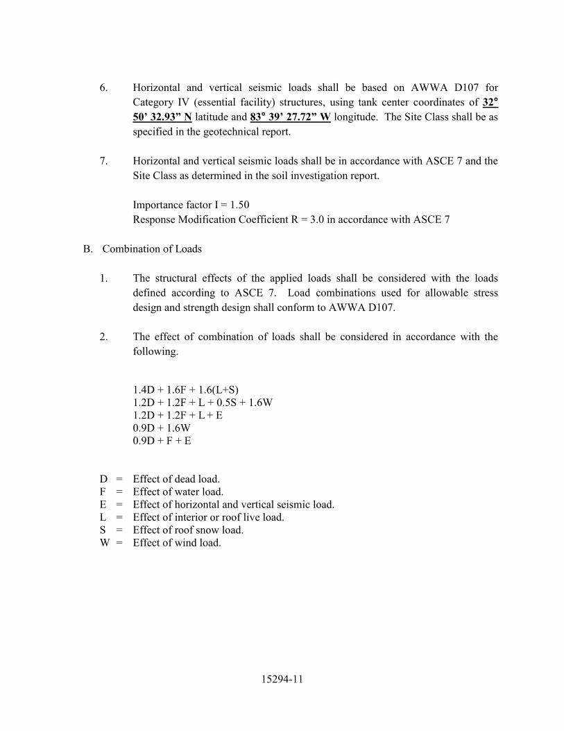
15294-11
6. Horizontal and vertical seismic loads shall be based on AWWA D107 for
Category IV (essential facility) structures, using tank center coordinates of 32° 50’ 32.93” N latitude and 83° 39’ 27.72” W longitude. The Site Class shall be as specified in the geotechnical report.
7. Horizontal and vertical seismic loads shall be in accordance with ASCE 7 and the
Site Class as determined in the soil investigation report.
Importance factor I = 1.50 Response Modification Coefficient R = 3.0 in accordance with ASCE 7
B. Combination of Loads 1. The structural effects of the applied loads shall be considered with the loads
defined according to ASCE 7. Load combinations used for allowable stress design and strength design shall conform to AWWA D107.
2. The effect of combination of loads shall be considered in accordance with the following.
1.4D + 1.6F + 1.6(L+S) 1.2D + 1.2F + L + 0.5S + 1.6W 1.2D + 1.2F + L + E 0.9D + 1.6W 0.9D + F + E
D = Effect of dead load. F = Effect of water load. E = Effect of horizontal and vertical seismic load. L = Effect of interior or roof live load. S = Effect of roof snow load. W = Effect of wind load.

15294-12
4.3 Concrete Foundation
A. Foundation Design Responsibility
The foundation design shall be by the Contractor and shall conform to the recommendations given in the geotechnical report. The foundation depth shall be as required for the extreme frost penetration shown in AWWA D107.
B. Design Criteria
1. The concrete foundation shall be designed in accordance with ACI 318.
Minimum specified compressive strength shall be 4000 psi at 28 days. The service load reinforcement tension stress shall not exceed 30,000 psi under dead plus water load unless flexural cracking is otherwise controlled in accordance with ACI 318.
2. Earth cover shall be a minimum of four (4) feet over top of pipe in accordance with AWWA D107. Any pipe passing through the foundation which does not meet this minimum cover requirement shall be properly insulated until such minimum cover is achieved.
3. Unless modified by the Geotechnical Engineer, the foundation shall be sized to
provide a safety factor of 3.0 against the ultimate soil bearing capacity in accordance with AWWA D107. For driven pile the safety factor shall be at least 2.0. Safety factors may be reduced to 2.25 and 1.5 respectively when direct vertical loads are combined with wind or seismic.
4. The foundation shall be sized such that there is a minimum safety factor of 1.5
against overturning for wind or seismic events using service load combinations. 5. Foundation piling shall conform to the design and detailing requirements of
International Building Code (IBC) Section 1810, including the supplemental design and detailing requirements based on the assigned Seismic Design Category (SDC).

15294-13
4.4 Concrete Support Structure
A. Design Requirements 1. The design of the concrete support structure shall conform to AWWA D107 and
ACI 318 except as modified herein.
2. The specified compressive strength of concrete shall be as required by design, but not less than 4000 psi at 28 days. The maximum specified compressive strength of concrete for the wall and dome shall be 6000 and 5000 psi respectively.
B. Support Wall
1. The minimum wall thickness shall not be less than 8 inches exclusive of rustications
or other architectural relief.
2. The concrete support structure walls shall have a minimum reinforcement ratio in accordance with AWWA D107 Table 13. Where the seismic design category determined in accordance with ASCE 7 is D, E or F, the minimum reinforcement ratio shall be 0.25% in the vertical and horizontal directions.
3. The concrete support structure walls shall have reinforcement placed in two layers in
each direction with 50% of the minimum required steel in each layer. 4. The vertical load capacity for walls shall be determined using the procedures in
AWWA D107 Section 6.3. 5. Horizontal reinforcement shall be provided to resist the ovalling of the wall due to
wind pressure, using the procedures in AWWA D107 Section 6.3. 6. The concrete support structure walls shall be designed to resist in plane shear using
the procedures in AWWA D107 Section 6.3. The effect of openings shall be considered in the shear design.
C. Openings 1. Openings in the concrete support structure walls that are less than or equal to 24
inches and are isolated do not require a beam and column analysis. Isolated openings shall have a clear distance between openings equal to 0.75 times the cumulative width of adjacent openings. Additional reinforcement having an area of

15294-14
not less than 1.2 times the area of interrupted reinforcement shall be distributed equally to either side of openings. Openings shall have a minimum of one No. 5 reinforcing bar placed diagonally in each corner. All reinforcing shall be fully developed beyond the opening.
2. Openings larger than 24 inches or combinations of openings that are not isolated shall be designed using an effective beam and column analysis as per AWWA D107 Section 6.3. Vertical and horizontal reinforcement shall be provided around the opening in accordance with the requirements of this section.
a. The corners of the openings shall be reinforced with diagonal bars. The area
of bars provided shall be equal to the minimum horizontal reinforcement ratio times the column area. A minimum of two No. 5 reinforcing bars shall be placed diagonally in each corner.
b. Reinforcement provided around openings shall be fully developed. Column reinforcement shall extend the greater of half the opening height or the development length above and below the opening or be developed into the foundation. Horizontal reinforcement shall extend the greater of the development length past the midpoint of the column or a minimum of half a development length beyond the column.
3. Local effects at openings shall be considered when the opening is located less than half the opening width above the foundation. The foundation shall be designed to adequately develop the opening reinforcement and redistribute loads across the unsupported width.
4.5 Concrete Support Structure / Steel Tank Interface
A. The concrete to tank interface region includes those portions of the concrete support
structure and welded steel tank that are affected by the transfer of forces between the concrete tank floor, ringbeam, tank cone bottom and support structure wall. The design of the interface region shall be based on an analysis using finite element or similar analysis which can accurately model the interaction of the intersecting elements. The analysis shall provide results including the shear, moment and compression or tension caused by the intersecting elements in the interface region.
B. The analysis shall consider the transfer of forces from the intersecting elements under all anticipated load conditions. These conditions shall include the eccentricity of loads, restraint effects caused by shrinkage and temperature differentials, long term effects

15294-15
caused by concrete creep, and the effect of anchorage of the welded steel tank to the concrete.
C. The geometry of the interface region shall provide positive drainage at the top of the wall and ringbeam. Condensation or precipitation shall not be allowed to accumulate in this area.
D. The geometry of the tank shall be established such that the ringbeam provided at the top of the wall is a compression member with gravity loads acting alone (D + F). In this loading condition the compressive stress in the ringbeam shall be not less than 50 psi to minimize cracking in the interface region. No direct tension in the ringbeam under this loading condition will be allowed. The maximum compression in the ringbeam shall be no greater than 0.18f'C.
E. The ringbeam shall be reinforced as a compression member with a minimum longitudinal reinforcement ratio of 0.40%. Tie reinforcement shall be provided in accordance with ACI 318 for compression members as a minimum. Additional tie reinforcement shall be provided if required by the analysis of the interface region.
F. When a concrete dome supports the tank contents, it shall not be less than 9 inches thick, or less than the mean spherical radius of the dome divided by 50. The minimum reinforcement ratio shall be 0.36% in orthogonal directions. The reinforcement shall be placed in two layers with 50% of the minimum required steel in each layer.
4.6 Welded Steel Tank
A. The design for all sections of the steel tank shall be per the unit tension/compression
stresses allowed for material classes listed in the latest edition of AWWA D107.
B. Roof plates and supporting structure shall be designed to support the roof snow and live loads specified in Section 4.2(A).
C. For areas of the steel tank where the water is supported by a steel cone, the cone plate thickness may be determined using a nonlinear buckling analysis. A nonlinear buckling analysis may only be performed for liquid filled cones with a thickness-to-radius ratio greater than 0.0010 and less than 0.0030. The angle of the cone measured from the axis of revolution to the plate surface shall not exceed 60 degrees. If a nonlinear buckling analysis is not performed, the cone plate thickness shall be determined in accordance with the shell stability formulas provided in AWWA D107.

15294-16
1. The nonlinear buckling analysis shall include the effects of material and geometric non-linearities, residual stresses and imperfections.
2. The imperfection considered in the analysis shall have a magnitude of not less than 0.04(Rt)1/2, where R is the radius normal to the plate measured to the axis of revolution, and t is the corroded plate thickness. The length of the imperfection shall be equal to or less than 4(Rt)1/2 and be appropriate for the type of construction used for the cone. The location and shape of the imperfection shall produce the lowest critical buckling stress.
3. The minimum specified yield strength of the cone plate material shall be equal to or greater than 36 ksi. The yield strength used for the analysis shall be no greater than 40 ksi when the material of construction has a minimum specified yield strength greater than 40 ksi.
4. Plate thickness used for the cone plates shall be no less than 80% of that required by the shell stability formulas provided in AWWA D107 when the thickness to radius ratio is greater than or equal to 0.00143. Cone plate thickness shall be no less than 70% of that required by AWWA D107 when the thickness to radius ratio is less than 0.00143.
5. The nonlinear buckling analysis shall demonstrate that the provided cone plate thickness has a factor of safety of at least 2.0 against buckling in the corroded condition.
D. The concrete tank floor shall be covered with a welded steel liner to provide a water tight boundary. The minimum thickness of the liner plate shall be 1/4-inch. Liner plates may be placed directly on the concrete when the liner plates are formed to match the shape of the tank floor. Liner plates that are not formed to match the shape of the tank floor shall have the space between the liner plates and the tank floor completely filled with a flowable grout.
E. Unless otherwise noted, at junctions in plates where meridional forces are discontinuous such as cone to cylinder junctions, a tension or compression ring may be required to resist the radial forces generated. In these regions, the allowable stresses shall not exceed those referred to in AWWA D107. 1. Tension ring stresses shall not exceed the lesser of 15,000 psi or one half of the
minimum specified yield of the plate material.

15294-17
2. Compression ring stresses shall not exceed 15,000 psi.
3. To determine the stresses in the ring due to discontinuity forces, the tank plates immediately adjacent to the discontinuity may be assumed to participate for a distance of 0.78(Rt)1/2.
F. Minimum plate thickness of all tank parts shall be in accordance with AWWA D107.
PART 5 – APPURTENANCES AND ACCESSORIES
5.1 Exterior Doors
A. Personnel Door(s)
Provide one 36-inch x 84-inch commercial steel door, 1¾” thick, 4¾” 16-gauge jamb, industrial duty type door closer and automatic door bottom. Door to be AMWELD series 1500 seamless door, with series 400 frame, or approved equal. Door shall be minimum 16-gauge and insulated with pre-formed polystyrene insulation. Door shall be thoroughly cleaned, phosphated and finished with one coat of baked-on rust inhibiting primer in accordance with ASTM B117 and ASTM D1735. Provide three (3) full mortise, 5 knuckle hinges, 4½” x 4½” minimum. Hinges shall be steel, phosphated and primed coated for finish painting. Provide a complete and functional door lockset and tumbler-type lock, keyed to the owner’s existing system. Door painting shall conform to the tank exterior paint system.
B. Overhead Door(s)
Provide one manually operated 10-foot wide by 10-foot high overhead steel rolling door located in the base of the support structure. Door slats shall be formed of 22-gauge steel with end locks and designed for a minimum 20-psf wind load. Steel curtain construction with high-grade zinc coating per ASTM A153 hot process, and phosphate coating for paint adhesion. Provide air baffle for entire upper barrel, curtain bottom bar with brush sealing, weather end lock on alternate slats and sealing strips for weather tightness. The door shall be equipped with slide bolt locks on both sides of interior bottom. Overhead door location shall be as shown on the drawings.
C. Safety Posts
Provide two (2) 8-inch diameter steel safety posts on the exterior of the overhead door opening to protect the door from vehicle impact. Safety posts shall be filled with concrete.

15294-18
5.2 Piping
A. Inlet / Outlet Pipe
A 36-inch diameter inlet/outlet pipe shall be provided from near the low point of the tank floor to a flanged connection at the base of the support structure. The inlet/outlet pipe shall be ASTM A240-304L material. Piping shall conform to ASTM A778 and welded fittings shall conform to ASTM A774. All pipe-to-pipe joints shall be welded. The pipe shall have a minimum thickness of schedule 10S but not less than 3/16-inch. Provide a stainless-steel expansion joint near grade to accommodate differential movements between the inlet/outlet pipe and concrete support structure. The inlet/outlet pipe shall be attached to the support structure with galvanized steel brackets spaced no more than 20 feet apart.
B. Inlet / Outlet Pipe Drain
A 16-inch diameter inlet/outlet pipe drain shall be provided from a tee on the inlet/outlet pipe. The drain line will be controlled with an isolation gate valve. On the discharge side of the isolation valve, the inlet / outlet pipe drain shall increase to 18-inch diameter. It shall then extend thru the interior floor slab and shall penetrate the support wall below grade. The inlet / outlet pipe drain shall connect to the site piping in the yard and discharge into the detention pond through a common pipe run with the overflow pipe drain.
C. Overflow Pipe 1. Pipe
A(n) 18-inch diameter overflow pipe equipped with an anti-vortex entrance shall be provided. The overflow pipe within the support structure shall be ASTM A240-304L material. Stainless steel piping shall conform to ASTM A778 and welded fittings shall conform to ASTM A774. The pipe shall have a minimum thickness of schedule 10S but not less than 1/8-inch. Inside the tank, the overflow pipe shall conform to ASTM A53 Grade B and have a minimum thickness of 1/4-inch. All pipe-to-pipe joints shall be welded. The overflow shall be attached to the access tube and support structure, and discharge at a point approximately two feet above grade level onto a splash block. The attachment to the support structure shall be with galvanized steel brackets spaced no more than 20 feet

15294-19
apart. The end of the overflow shall be covered with a No. 4 galvanized steel wiremesh screen.
2. Pipe Entrance The entrance to the overflow pipe shall be designed for the maximum overflow rate specified in 2.1(B). The design shall be based on the water level cresting within 6 in. above the overflow elevation. A conical weir shall be provided if the entrance capacity of the overflow pipe diameter is not adequate. A vortex prevention device shall be used.
3. Pipe Discharge The overflow pipe shall extend thru the interior floor slab and shall penetrate the support wall below grade. The overflow pipe shall connect to the site piping in the yard and discharge into the detention pond through a common pipe run with the inlet / outlet pipe drain.
D. Tank Drain Pipe
A 3-inch diameter tank drain pipe shall penetrate the tank at the low point of the tank floor. The drain pipe shall be fitted with a threaded plug and handle inside the tank and have a wall thickness equal to or greater than standard weight pipe. The drain pipe shall conform to ASTM A53 Grade B and all pipe-to-pipe joints shall be welded. A NSF approved flexible pipe shall be used to connect the drain pipe to the overflow pipe.
E. Stainless Steel Requirements
1. Pipe and fittings shall be Type 304L stainless steel fabricated from material meeting the requirements of ASTM A-240. Fabrication, inspection, testing, marking and certification of pipe and fittings shall be in accordance with ASTM A-778 and A-774 respectively. All fittings less than 18 inches shall be smooth flow, fittings larger than 18 inches may be of five section mitre construction. Backing flanges shall be in accordance with ASTM A285-C drilled to ANSI B16.5 Class 150. Pipe, fittings and welds shall be cleaned and passivated.
2. Pipe, fittings and flange thickness shall be in accordance with the manufacturers certified pressure rating for the applicable service pressures. The design pressure rating shall be minimum 125 psi for piping located within closed or valve sections.

15294-20
5.3 Ventilation
A. Tank Ventilation 1. Tank Vent
A tank vent shall be provided, located centrally on the tank roof above the maximum weir crest elevation. It shall consist of stainless steel or aluminum components, including a support frame, screened area and cap. The support shall be fastened to a flanged opening in the tank roof. The vent cap shall be provided with sufficient overhang to prevent the entrance of wind driven debris and precipitation. A minimum of 4 in. shall be provided between the roof surface and the vent cap. The tank vent shall have an intake and relief capacity sized to prevent excessive pressure differential during the maximum flow rate of water, either entering or leaving the tank. The overflow pipe will not be considered as a vent. The maximum flow rate of water entering the tank is specified in 2.1(B). The maximum flow rate of water exiting the tank shall be the maximum of the withdrawal rate specified in Section 2.1(B), or the drain rate specified in Section 2.1(B), or as calculated assuming a break in the inlet/outlet pipe at grade when the tank is full. The vent shall be provided with an insect screen. Vent capacity shall be determined based on open area provided by the screen.
2. Pressure / Vacuum Relief Mechanism In addition to the tank vent, a pressure/vacuum relief mechanism shall be provided that will operate in the event of vent failure. The mechanism shall be designed to return automatically to its original position after operation. The pressure/vacuum relief mechanism shall be located on the tank roof above the maximum weir crest elevation, and may be incorporated in the vent assembly.
B. Support Structure Ventilation
Ventilation within the support structure shall comply with the governing building code requirements, based on occupancy classification. As a minimum, one louvered vent shall be provided at the top of the support wall. This vent shall be accessible from the upper platform and may also be designed to provide access to the exterior rigging rails located at the tank/support wall intersection. Vents shall be accessible from the interior ladders, platforms or floors provided. Vents shall be stainless steel or aluminum and provided with a removable insect screen.

15294-21
5.4 Access, Stairs, Ladders, and Platforms
A. Stairs
1. Provide an aluminum access stairway adjacent to the support wall. Access openings through the structural floor shall be protected with 42 inches high aluminum handrails.
2. Construct stairs and platforms using aluminum plate for the stair stringers and grating style stair treads. The stair treads shall be aluminum and bolted to the stringers. All stair and platform components shall be aluminum.
3. Provide two (2) intermediate rest platforms.
B. Ladders 1. Provide a painted steel ladder on the interior of the access tube from the walkway
to the tank roof. This ladder shall be equipped with a ladder safety cable.
2. Provide a galvanized steel ladder from the walkway to the tank bottom manhole. This ladder shall be equipped with ladder safety cable.
3. A ladder for access to the tank interior from the roof shall be provided and attached to the access tube.
4. Ladders that terminate at platforms or landings shall extend a minimum of 48 in.
above the platform elevations. A safety extension shall be provided at the top of the ladder under hatch(s). The safety extension shall be a Ladder Up Safety Post as manufactured by Bilco or equal. The post shall extend 42-inches above the top of the ladder and be constructed of hot dip galvanized steel. Mounting hardware shall be galvanized.
5. Ladders located in the concrete support structure and access tube interior shall be
galvanized steel. Tank interior ladders shall be coated in accordance with the tank interior coating system.
6. Ladder side rails shall be a minimum 3/8 in. by 2 in. with a 16 in. clear spacing.
Rungs shall be minimum 3/4 in. diameter, spaced at 12 in. centers and plug welded into holes drilled in the side rails. Tank interior ladders shall be provided with 1 in. diameter rungs and 1/2 in. x 2 in. side rails and shall be fully seal welded.

15294-22
7. Ladder shall be secured to the adjacent structure by brackets located at intervals
not exceeding 10 ft. Brackets shall be of sufficient length to provide a minimum distance of 7 in. from the center of rung to the nearest permanent object behind the ladder. Ladder brackets located on the access tube exterior shall be reinforced at the access tube shell so that potential ice damage is confined to the ladder and bracket and not the access tube shell.
C. Rest Platforms
1. Rest platforms shall be a minimum 5 ft. by 3’-6” ft. and complete with handrails, mid rails and toe plates in accordance with OSHA requirements. Grating shall be used for the walking surface. All components shall be aluminum.
D. Walkways
1. Provide an aluminum walkway immediately below the tank extending from the
support structure to the access tube. The walkway shall be a minimum of 48 inches wide with 42-inch high handrails.
E. Access Tube 1. Provide an access tube located on the vertical centerline of the tank. The access
tube shall have a minimum diameter of 48 inches. The access tube shall extend below the tank floor to the walkway level to provide continuous ladder access from the walkway to the tank roof.
2. The access tube shall incorporate a 2 in. by 2 in. channel to collect condensation that may form on the interior surface. A flexible 3/4 in. PVC hose complete with backflow preventer shall drain the channel to the overflow pipe.
F. Safe Climbing Device 1. The ladder safety cable shall be an OSHA approved galvanized system as
manufactured by DBI-Sala, or equal. Provide a removable extension for each ladder that does not extend 48 inches beyond the walkway level. The owner shall be supplied with 2 harnesses, 2 lanyards and 2 sleeves.
2. High strength aluminum, rigid rail safe climbing devices shall be provided on all ladders. Rails shall be center mounted and extend from 3 ft. above the ladder

15294-23
bottom to the top of the ladder section. Mounting brackets, fasteners and splice bars shall be provided as required for a rigid installation.
3. Three trolleys with snap hooks shall be provided that are designed to be operated with the aluminum rail. A safety body harness with front and side rings shall be supplied for each trolley.
4. A caution sign shall be provided at the lowest point of access to the ladder requiring safe climbing devices. The sign shall read “CAUTION – Safety Equipment Required When Climbing Ladder “. The sign shall be secured to the wall.
5.5 Manholes, Hatches, and Openings
A. One 24-inch x 36-inch painter’s access manhole/ventilation louver opening shall be provided giving access to the exterior painter’s rail located at the top of the concrete support structure. This opening shall have a removable aluminum rainproof louver with bird screen to provide ventilation for the concrete support structure. The louver shall be accessible from the walkway. The painter’s access manhole serves a dual purpose with the ventilation function described in Section 5.3(B).
B. Provide a 30 in. diameter manhole through the tank floor. The manhole shall be operable from a ladder located on the upper platform and shall be designed to withstand the pressure of the tank contents without leakage. The manhole assembly shall include a stainless steel hand wheel operator and threaded components.
C. Two 30-inch diameter steel hatches shall be supplied. One shall be at the top of the access tube with spring assist, chain, hook, and inside handle. The other shall be adjacent to the access tube for entry into the tank and shall have a handle and hasp with access to the interior of the tank via the ladder mounted on the exterior of the access tube. The hatch openings shall have a curb four inches high and the cover shall have a downward overlap of two inches.
D. One 24-inch diameter flanged exhaust hatch shall be supplied, located adjacent to the access tube and so constructed that an exhaust fan may be connected for ventilation during painting.

15294-24
E. One 24-inch diameter painter’s access manhole shall be provided adjacent to each interior painter’s rail giving access from the roof. The 24-inch diameter exhaust hatch may be positioned to serve as one of these access manholes.
5.6 Painter’s Rails
Provide painter’s rails and an interior inspection rail as shown on the drawings and specified herein:
A. Interior Painter’s Rails 1. The rails shall be attached to the underside of the roof. Provide one rail near the
center of the tank and one rail approximately 18 inches from the tank shell. If the slope distance between these two rails exceeds 32 feet, provide a third rail near midspan.
B. Exterior Painter’s Rails 1. The rail shall be located near the top of the support structure and be accessible
from the walkway via the painter’s access manhole / ventilation louver.
C. Interior Inspection Rail 1. The rail shall be located near the top of the support structure and be accessible
from the walkway. The rail and support brackets shall be galvanized.
5.7 Crow’s Nest
Provide a 3’ wide crow's nest platform around the access tube inside the tank above the TCL for tank inspection. The crow’s nest shall have FRP grating plate (non-skid), and a 3’-6” high handrail all around. Provide opening in the access tube to the crow’s nest platform. Provide tank access ladder from the platform with a chained opening to the ladder.

15294-25
5.8 Roof Antenna Rail and Cable Details
Provide all labor, materials, equipment and installation to make all necessary provisions for future antenna cable(s) routing. This work includes but is not limited to the following:
A. Rail 1. Provide a 48-inch high circular roof handrail (carrousel), 20 feet in diameter, to
encompass all centrally located roof appurtenances. The roof handrail (carrousel) shall be 48 inches high and shall include a top rail, two (2) intermediate rail(s), and toe board. The handrail must be constructed to meet all OSHA requirements.
2. For safety considerations during antenna installation, and for maintenance, the handrail shall be furnished. The handrail shall also provide an attachment point for the future antenna(s).
B. Cable(s)
1. Three (3) 6-inch diameter pipe penetrations (spare conduits with caps) shall extend thru the concrete floor slab for future use. The spare conduits shall turn 90 degrees below grade and extend thru the concrete support structure. The spare conduit(s) shall terminate 18-inches above the finished floor slab elevation.
2. Three (3) 6-inch diameter pipe penetrations (with caps) in the access tube cover.
3. Cable raceways shall be mounted to the interior face of the concrete support structure between the concrete floor slab and the access tube. The raceways will be used for future cable runs.
4. Suitable brackets welded to the inside of the support structure and access tube to
safely secure future antenna cables. Bracket spacing shall not exceed 8 feet.
5.9 Lightning Protection
Provide a lightning protection system for the elevated tank structure and any roof mounted equipment that may be damaged by lightning.
Minimum requirements include two 28 strands by 14-gauge copper conductors bonded to the steel tank 180 degrees apart. The conductors shall be fastened to the interior support wall at 3 feet minimum spacing and shall terminate with buried 5/8-inch diameter by 8-foot-long copper clad ground rods.

15294-26
Lightning protection for obstruction lights shall consist of an air terminal mounted on the support and formed to fit around the fixture. The 1/2-inch diameter copper air terminal shall extend a minimum of 10 inches above the light fixture and shall connect to a copper conductor that terminates in a bonding plate secured to the tank roof.
5.10 Interior Floor
A. Slab on Grade
1. Provide a 6 in. thick, 3500 psi concrete floor slab on grade in the base of the
support structure. The slab shall be supported on compacted granular fill and shall be reinforced with #4 reinforcing steel at 12 in. centers each way. Provide 1/2 in. expansion joint between floor slab and support wall and at pipes and supports that extend through the floor. Place cap strip and sealant over the expansion joint. The slab shall be sloped at 0.5% toward the truck door and/or toward the floor drain (if shown on the plans) for drainage.
PART 6 – ELECTRICAL AND LIGHTING
6.1 Referenced Specification Electrical work shall be in accordance with Division 16 and the plan E-sheets.
6.2 Interior Lighting and Electrical Interior waterproof light sockets with rigid conduit, wiring and switch shall be provided inside the support structure and access tube. There shall be one light located at the top of the access tube, one light at the lower end of the access tube above the walkway opening, one light at each of the support structure ladder rest platforms, and one light at the base of the support structure. Total number and location of lights shall be as shown on the drawings. All wiring shall be in conduit. The conduit and wiring shall terminate with a junction box in the base of the tower. Duplex outlets shall be installed as shown on the drawings. Electric service shall be provided and connected by others..

15294-27
6.3 Exterior Lighting Exterior lighting shall be provided above the access door(s) and/or overhead door(s) for added security, and exterior lighting around the base of the support structure at ground level to illuminate the tank and/or support structure for aesthetic effect.
6.4 Obstruction Lighting In accordance with the Purchaser’s FAA Determination Letter, a double obstruction light shall be provided on the roof of the tank near the apex. The lights shall be enclosed in aviation red obstruction light globes as approved by the FAA, complete with an automatic photo-electric cell type switch. The contractor shall install all conduit and wiring from the light to the electrical service panel.
PART 7 – COATINGS AND FINISHES
Refer to Section 09902 for tank coatings. Galvanized, stainless steel and concrete surfaces are not coated.
PART 8 – EXECUTION
8.1 General
A. All concrete formwork, placement and consolidation shall comply with ACI 318 and ACI 301 except as modified herein. Concrete tolerances shall comply with ACI 117 except as modified herein.
B. Concrete placed in cold weather conditions shall be protected to prevent damage in accordance with ACI 306. The cold weather protection shall continue until the concrete has attained 35% of the specified compression strength and the allowable temperature differential can be maintained.
C. Concrete placed in hot weather conditions shall be protected to prevent damage in accordance with ACI 305.
D. Concrete shall be cured in conformance with ACI 318. Curing methods shall be continued until the concrete has reached a compressive strength that will allow for safe jumping of forms without causing damage to previously placed concrete.

15294-28
E. Concrete strength tests shall be taken in accordance with ACI 318 except as modified herein. Strength test samples shall be taken as the concrete is delivered from the truck. At least one strength test sample shall be taken for every day that concrete is placed. Additional strength test samples shall be taken for every 50 yd3 of concrete placed when the total daily pour is less than or equal to 150 yd3 and for every 150 yd3 of concrete placed when the total daily pour is greater than 150 yd3.
F. Each strength test sample shall provide at least four 6” x 12” molded cylinders. Two cylinders will be used to establish the 28-day strength in accordance with ACI 318. One cylinder should be tested at 7 days to supplement the 28-day test. The fourth cylinder shall be a spare for the other cylinders.
G. Inspection and testing of the welded steel tank shall comply with AWWA D107 Section 9.
8.2 Concrete Foundation
A. If, during excavation, conditions are encountered which differ from those given in the
geotechnical report, appropriate adjustments to construction schedule and price will be negotiated.
B. An inlet/outlet pipe extending a minimum of three feet outside the foundation wall shall be included as part of the foundation.
C. All exposed formed surfaces shall receive a smooth as-cast form finish and all unexposed formed surfaces shall receive a rough form finish. All exposed unformed surfaces shall receive a trowel finish and all unexposed unformed surfaces shall receive a float finish.
D. Provide a 6-inch-thick concrete slab at grade in the base of the support structure. The slab shall be placed over compacted structural backfill and shall be reinforced with welded wire reinforcement. Provide 1/2-inch expansion material at the slab to foundation intersection and at floor penetrations. Provide saw-cut control joints at 18 feet maximum spacing. The slab shall be sloped towards the floor drain. The slab shall be constructed in accordance with the latest edition of ACI 301.
E. All concrete work shall comply with ACI 301.

15294-29
8.3 Concrete Support Structure A. The concrete support structure wall shall be constructed using a jump form process. The
form system shall use curved, prefabricated form segments of the largest practical size to minimize panel joints. Concrete pour height shall be a minimum of 4 feet and a maximum of 12 feet. Form panels shall extend the full height of the concrete pour using only vertical panel joints. Formwork shall be secured using bolts through the wall prior to concrete placement. Working platforms that allow safe access for inspection and concrete placement shall be provided. Form facing material shall be metal, or plywood faced with plastic or fiberglass.
B. The form system shall incorporate a uniform pattern of vertical and horizontal rustications to provide architectural relief to the exterior wall surface. Construction joints and formwork panel joints shall be located in rustications. Formwork panel joints shall be sealed using closures which combine with the form pattern to prevent grout leakage and panel joint lines. The top of each concrete placement shall be finished with a grade strip. The vertical and horizontal rustications shall be proportioned and combined to impart a symmetrical architectural pattern to the completed structure.
C. Support wall forming system shall incorporate segmented concrete placement. Temporary vertical bulkheads shall divide the wall pour into segments that are less than a single batch of concrete. The bulkheads shall be located at rustications, braced rigid and tight to maintain vertical alignment under concrete load. Each segment shall be continuously placed with concrete to the full form height. Temporary bulkheads shall not be removed until adjacent concrete is placed.
D. Formwork shall remain in place until the concrete has attained sufficient strength to support the form removal and subsequent loads without damage to the structure. The Contractor shall base formwork removal procedures and times on early-age test results. However, form movements and concrete placement shall be limited to a maximum of once per day.

15294-30
E. Dimensional tolerances for the concrete support structure shall be checked by the contractor prior to each pour and maintained as the structure is built. The tolerances for construction of the concrete support structure are:
1. Support wall variation:
Thickness …………………….. -3%, +5% Diameter ……………………… 0.4% ≤ 3 inch Vertical alignment:
in any 10 feet of height ….. ½ inch in any 50 feet of height ….. 1 inch over total height ………….. 1 ½ inch
2. Tank floor variation:
Slab floor thickness …………. -3%, +5% Dome floor thickness ………... -6%, +10% Dome floor radius ……………. 1% Local deviation from true …… 3/4 inch (Using a 5-foot sweep board)
3. Level alignment variation:
From specified elevation ……. 1 inch From a horizontal plane …….. 1/2 inch
4. Offset between formwork:
Exterior exposed surfaces ….. 1/8 inch Interior exposed surfaces …... 1/4 inch
F. All exterior exposed surfaces shall receive a smooth as-cast form finish. All interior
exposed surfaces shall receive a rough as-cast form finish. All exposed surfaces shall be cleaned to remove surface contamination. All tie holes and concrete voids larger than 3/4-inch diameter and/or ½-inch deep shall be filled with a color matching nonshrink grout. All exposed surfaces shall be cleaned to remove any concrete paste leakage from higher placed concrete shaft rings. No additional finish of the exterior exposed surface is required unless excessive form oil remains on the concrete surface.
G. The top of the concrete tank floor shall receive a float finish.

15294-31
8.4 Welded Steel Tank
A. All welding shall comply with AWWA D107.
B. All welding procedures, welders and welding operators shall be qualified in accordance with ASME Section IX for the processes and positions utilized.
C. To minimize corrosion and rust staining on the underside of the roof, the underside roof plate laps and rafter-to-roof plate seams shall be seal welded. The minimum thickness for seal welded roof plates shall be 1/4 inch.
D. The edges or surfaces of the pieces to be joined by welding shall be prepared by flame cutting, plasma arc cutting, arc gouging, machining, shearing, grinding or chipping and shall be cleaned of detrimental oil, grease, scale and rust. The edges of the pieces may have a protective coating applied to them which need not be removed before they are welded unless specifically prohibited by the welding procedures.
E. Field and shop welding may be done by the shielded metal arc welding process, the gas metal arc welding process, the flux core arc welding process and the submerged arc welding process.
F. Plates and component members of the tank shall be assembled and welded following erection methods which result in a minimum of distortion from weld shrinkage. Surfaces to be welded shall be free from loose scale, slag, heavy rust, grease, paint and other foreign material.
G. The Contractor shall remove weld of slag, spatter, burrs and other sharp or rough projections. The surface of the weld shall be suitable for subsequent cleaning and painting operations.
H. Full penetration butt-welded joints shall be inspected using the radiographic examination method. The number and location of the radiographs and the acceptance criteria shall be as required by AWWA D107. Inspection by sectional segments is not allowed.
I. All liner plate welds shall be tested using the vacuum box testing method before the tank is painted.
J. When the cone plate thickness has been determined using a nonlinear buckling analysis, the contractor shall measure the actual imperfections of the cone plates after welding. The measurements shall be taken in the meridional direction. Measurements shall be

15294-32
taken at each meridional weld seam and midway between each meridional weld seam. Where the actual imperfections exceed the tolerances assumed in the analysis, further evaluation will be required and corrective action such as reworking the shell or adding stiffeners may be required.
K. In order to assist in the maximization of the paint’s lifecycle, all welds on the tank exterior shall be ground smooth and blended to a NACE-D profile. All welds on the tank interior shall be ground smooth and blended to a NACE-D profile. Welds on the interior dry support column can remain in an as-welded condition but must have a profile adequate for the specified paint system. Engineer/Owner reserves the right to provide third-party inspection to ensure compliance to this requirement.
8.5 Field Quality Control
A. Concrete Testing and Inspection 1. The evaluation and acceptance of concrete shall be in accordance with Section
03300 of this specification.
2. The support wall radius, plumb and thickness shall be verified for each concrete lift at all vertical form panel joints and at a minimum of 60 degree intervals. Vertical alignment and radius shall be checked using a visible beam laser. Measurement shall be made to the outside form surface. A log of the measurements and an inspection report certified by the tank designer shall be provided to the Owner at project completion.
B. Steel Tank Testing and Inspection
1. Inspection procedures for the steel tank shall be in accordance with AWWA D107, Section 9, "Inspection and Testing". Radiographic inspection of full penetration butt-welded joints shall be made by an independent inspection company retained by the Contractor.
2. Erection tolerance of the steel cone in the radial direction shall be measured. Provide field measurements at 30 degree intervals.
3. Weld joints of plate over the structural concrete floor shall be tested for leaks by
vacuum box / soap solution testing, or equivalent method prior to grouting.

15294-33
8.6 Cleaning
A. Site 1. The project site shall be kept in a clean and safe condition at all times. The
Contractor shall remove all construction equipment and debris at project completion.
PART 9 – TESTING AND STERILIZATION
9.1 Final Coat Sufficient cure, per the manufacturer's recommendations, of the final coat on the interior wet surface shall be allowed before the elevated tank is sterilized and filled with water.
9.2 Sterilization The tank shall be sterilized per the requirements of AWWA C652 -- Chlorination Method No. 2 or 3.
9.3 Test Water The Owner, free of charge to the Contractor, shall furnish and dispose of sufficient water for flushing, cleaning, testing, and sterilization. The water shall be at proper pressure to fill the tank to the maximum working level. Any leaks in the tank that are disclosed by this test shall be repaired by gouging out defective areas and re-welding. No repair work shall be done on any joint unless the water in the tank is at least two feet below the joint being repaired. Any paint damaged by repairs shall be properly restored.
9.4 Bacteriological Test Upon completion of the sterilization procedure, the Owner or his representative shall arrange and bear the cost of any bacteriological testing of water samples from the tank that may be required. The tank shall not be placed in service until safe test results are obtained.

15294-34
PART 10 – GUARANTEE
The Contractor shall guarantee its work for a period of one year from the date of substantial completion. Substantial completion is defined as the date when the tank is placed, or available to be placed, into service. The Contractor will repair any defects of which they are notified during that period which may appear because of faulty design, workmanship or materials furnished under the specifications. Defects caused by damaging service conditions such as electrolytic, chemical, abrasive or other damaging service conditions are not covered by this guarantee.
All guarantees and extended warranties offered by the manufacturer or installer of paint, equipment or accessories not manufactured by the Contractor shall be obtained by the Contractor directly from the manufacturer or installer. The Contractor shall provide the Owner a copy of all such guarantees and warranties.

15320 - 1
SECTION 15320 Tank Mixing System –
Reservoir Hydrodynamic Mixing System (HMS)
1.0 General
1.1. The Hydrodynamic Mixing System (HMS) is defined as a supplemental system installed within a potable water storage reservoir which passively utilizes the energy provided by the inlet water supply (via pumped or gravity head) and generates a sufficient inlet momentum to achieve a complete homogeneous blending of the water volume within the reservoir with the inlet supply flow. Determination of Complete Homogeneous Blending shall be defined by the modeling requirements and supporting hydraulic analysis as conducted by each individual manufacturer for their specific system configuration as defined within these specifications. System submittals not providing this validation shall not be considered as a viable Hydrodynamic Mixing System (HMS) and shall not be accepted as an equivalent to this system specification.
1.2. The specifications in this section include all components of the Reservoir Hydrodynamic
Mixing System (HMS) consisting of a bi-directional flow manifold equipped with variable orifice duckbill inlet nozzles and outlet flow check valves that are NSF61 certified. The HMS manufacturer shall be responsible for designing the system in accordance with the hydrodynamic criteria defined within these specifications and submit design calculations verifying compliance in accordance with the submittal requirements. The following is a description of the Hydrodynamic Mixing System.
1.3. All modeling and hydraulic and mixing calculations pertaining to the HMS shall originate
from the duckbill valve manufacturer. Modeling and calculations provided by parties other than the duckbill valve manufacturer are not allowed.
1.4. The complete Hydrodynamic Mixing System shall be supplied by the variable orifice nozzle
manufacturer to maintain single source responsibility for the system. The complete system shall be defined as all piping and appurtenances within the tank downstream of the tank penetration. Appurtenances include pipe, fittings, horizontal and vertical pipe supports, expansion joints, variable orifice duckbill check valves, and any other equipment specified within this section of the specifications. Approved manufacturer is Tideflex Technologies, Carnegie, PA 15106. Local Representative is Kazmier and Associates, Inc. (1-770-475-2242).
1.5. Manufacturer’s and/or contractors submitting an alternative to the named Tideflex
Technologies mixing system shall be responsible for obtaining any and all proprietary rights, license fees, royalties, technology licenses, and/or permissions required to provide such a system. The Manufacturer shall indemnify and hold harmless the Owner and Engineer against all claims, damages, losses, and expenses arising out of any infringement of patent rights or copyright incident relating to this system.
2.0 Referenced Standards

15320 - 2
American National Standards Institute (ANSI) B16.1 – Cast Iron Pipe Flanges and Flanged Fittings B16.5 – Pipe Flanges and Flanged Fittings B36.10 – American National Standard Weights and Dimensions of Welded and
Seamless Wrought Steel Pipe
American Society for Testing and Materials (ASTM) A53 – Standard Specification for Pipe, Steel, Black and Hot-Dipped, Zinc-
Coated, Welded and Seamless A234 – Standard Specification for Piping Fittings of Wrought Carbon Steel
and Alloy Steel for Moderate and High Temperature Service A240 – Standard Specification for Chromium and Chromium-Nickel Stainless Steel Plate, Sheet, and Strip for Pressure Vessels and for General Applications A351 – Standard Specification for Castings, Austenitic, Austenitic-Ferritic
(Duplex), for Pressure-Containing Parts A536 – Standard Specification for Ductile Iron Castings C110 – Ductile Iron and Gray-Iron Fittings, 3 In. through 48 In. for Water D1330 – Standard Specification for Rubber-Sheet Gaskets D1784 – PVC/CPVC Pipe Compounds D1785 – PVC Pipe, Schedules 40, 80 & 120 D2466 – PVC Solvent Cement D2855 – PVC Solvent Joints D3261 – Butt Heat Fusion Polyethylene (PE) Plastic Fittings for Polyethylene (PE) Plastic Pipe and Fittings D3915 – PVC Pipe Fitting Compounds American Iron and Steel Institute (AISI) AISI 304 – 304 Stainless Steel Plate AISI 316 – 316 Stainless Steel Plate AISI 1040 – Carbon Steel Plate American Water Works Association (AWWA) C104 – Cement-Mortar Lining of Ductile Iron Pipe and fittings for Water C110 – Ductile-Iron and Gray-Iron Fittings, 3 In. through 48 In. for Water C115 – Flange Ductile Iron Pipe with Ductile Iron or Gray Iron Threaded Flanges C200 - AWWA Standard for Steel Water Pipe 6” and Larger C207 – Standard for Steel Pipe Flanges for Waterworks Service – Size 4
In. to 144 In. C220 – AWWA Standard for Stainless Steel Pipe, 4” and Larger C900 – AWWA Standard for Polyvinyl Chloride (PVC) Pressure Pipe, 4
In. Through 12 In. for Water Distribution C905 – AWWA Standard for Polyvinyl Chloride (PVC) Pressure Pipe
and Fabricated Fittings, 14 In Through 48 In. for Water Transmission and Distribution
C906 – AWWA Standard for Polyethylene (PE) Pressure Pipe and Fittings, 4 In. Through 63 In. for Water Distribution

15320 - 3
American Water Works Association Research Foundation (AwwaRF) Project No. E20-J08 – Physical Modeling of Mixing in Water Storage Tanks (Forthcoming) National Sanitation Foundation (NSF) NSF Standard 14 – Plastic Piping System Components and Related Materials NSF Standard 61 – Drinking Water System Components – Health Effects
3.0 Variable Orifice Duckbill Inlet Nozzles
3.1. Inlet ports/nozzles shall be duckbill-style check valves that allow fluid to enter the reservoir during fill cycles and prevent flow in the reverse direction through the nozzle during draw periods. Inlet ports/nozzles may not be fixed-diameter ports or pipes.
3.2. The duckbill valves shall be NSF61 Certified. NSF61 approved/Certified materials will not
be accepted in lieu of valve certification.
3.3. Inlet ports/nozzles shall have a variable diameter vs. flow hydraulic profile that provides a non-linear jet velocity vs. flow characteristic and a linear headloss vs. flow characteristic. The hydraulic characteristics of the duckbill valves shall be defined by “Hydraulic Code”.
3.4. The inlet ports/nozzles shall discharge an elliptically shaped jet. The nozzle must have been
modeled by an independent laboratory using Laser Induced Fluorescence (LIF).
3.5. Manufacturer shall have conducted independent hydraulic testing to determine headloss and jet velocity characteristics on a minimum of eight (8) sizes of duckbill valves ranging from 2” through 48”. The testing must include multiple constructions (stiffness) within each size and must have been conducted for free discharge (discharge to atmosphere) and submerged conditions.
3.6. Manufacturer shall have conducted an independent hydraulic test where multiple valves (at
least four) of the same size and construction (stiffness) were tested to validate the submitted headloss characteristics and to prove the repeatability of the manufacturing process to produce the same hydraulic characteristics.
3.7. Manufacturer shall have conducted independent hydraulic testing to study the flow
distribution characteristics of duckbill valves installed on multiport manifolds.
3.8. Manufacturer to have conducted Finite Element Analysis (FEA) on various duckbill valves to determine deflection, stress, and strain characteristics under various load conditions. Modeling must have been done for flowing conditions (positive differential pressure) and reverse differential pressure.
3.9. Manufacturer must have conducted in-house backpressure testing on duckbill valves ranging
from ¾” to 48”. 3.10. Manufacturer shall have at least fifteen (15) years experience in the manufacturing of
“duckbill” style elastomeric valves.

15320 - 4
3.11. Manufacturer must have duckbill valves installed on manifold piping systems in at least 100
distribution system reservoirs.
3.12. Manufacturer must have representative inspection videos showing the duckbill valves discharging water into the reservoir during an initial fill (unsubmerged). Manufacturer must also have representative underwater inspection videos showing the operation of the valves when submerged. Representative videos can be submitted upon request from the engineer.
3.13. The duckbill style nozzles shall be one-piece elastomer matrix with internal fabric reinforcing
designed to produce the required discharge velocity and minimum headloss requirements as stipulated in the Submittals section. The flange portion shall be an integral portion of the nozzle with fabric reinforcing spanning across the joint between the flange and nozzle body.
3.14. The elastomer used in construction of the duckbill valves must have been tested by an
accredited independent laboratory that confirmed there is no degradation in the elastomer when exposed to chlorine and chloramine per the ASTM D471-98 “Standard Test Method for Rubber Property – Effect of Liquids.”
3.15. The manufacturer’s name, plant location, serial number and product part number which
designates nozzle size, material and construction specifications shall be bonded onto the surface of the nozzle.
4.0 Outlet Check Valves
4.1. The outlet flow valves shall be perforated disc type with elastomeric membrane. 4.2. The valves shall be NSF61 Certified. NSF61 approved/Certified materials will not be
accepted in lieu of valve certification. 4.3. The perforated disc shall be fabricated of stainless steel plate with welded support gussets.
The disc shall be flanged and drilled to mate with ANSI B16.1, Class 125/ANSI B16.5 Class 150 flanges. The disc shall have three (3) tapped holes used for fastening the membrane and support rod to the disc with stainless steel bolts, nuts, and lock washers. The top of the disc shall be tapped and supplied with lifting eyebolt for installation.
4.4. The membrane shall be circular, one piece rubber construction with fabric reinforcement. The
diameter of the membrane shall allow adequate clearance between the membrane O.D. and the pipe I.D. The membrane shall be vulcanized with a specified convex radius to produce a compression set to allow the membrane to seal against the perforated disc at low reverse differential pressure.
4.5. The support rod shall be stainless steel and drilled with three (3) longitudinal holes to allow
fastening of rod to membrane and perforated disc. 4.6. When line pressure inside the valve exceeds the backpressure outside the valve, the line
pressure forces the membrane to open, allowing flow to pass through the perforations in the

15320 - 5
disc. When backpressure exceeds the line pressure, the membrane seats on the perforated disc preventing backflow.
4.7. The valve allows flow out of the reservoir during draw cycles and prevents flow into the
reservoir during fill cycles. 4.8. The elastomer used in construction of the membrane must have been tested by an accredited
independent laboratory that confirmed there is no degradation in the elastomer when exposed to chlorine and chloramine per the ASTM D471-98 “Standard Test Method for Rubber Property – Effect of Liquids.”
4.9. The manufacturer’s name, plant location, serial number and product part number which
designates membrane size, material and construction specifications shall be bonded onto the surface of the membrane.
5.0 Carbon Steel Pipe and Fittings
5.1. Carbon steel pipe and fittings shall conform to the associated standards listed in Section 2.0: Reference Standards.
5.2. Dimensions for carbon steel fittings shall conform to AWWA C110, unless otherwise
specified.
5.3. Wall thickness for carbon steel pipe and fittings shall be specified by Schedule conforming to ANSI B36.10-1985.
5.4. Wall thickness and dimensions of carbon steel tubing shall be given in exact dimensions in
fractions of an inch, not by gage number.
5.5. All flanges shall be carbon steel ring flanges conforming to AWWA C207 Class D. Flange drilling pattern shall be in accordance with ANSI B16.1/B16.5 standards.
5.6. Ring flanges shall be continuously welded on both sides.
5.7. Welding of carbon steel pipe and fittings shall be in accordance with the Reference standards.
5.8. All butt welds shall be fully penetrated with gas shielding to the interior and exterior of the
joint.
5.9. Welded cross-sections shall have a thickness equal to or greater than the welded material.
5.10. Field welding of carbon steel pipe and fittings will not be allowed unless approved by the Engineer.
5.11. All welded joints shall be free of sharp edges and burrs.

15320 - 6
5.12. Coating of the inside of carbon steel pipe and fittings is not required, unless otherwise specified.
5.13. Coating of the outside of carbon steel pipe and fittings shall be performed in the field, by the
contractor, following installation of the manifold piping system. Surface preparation and coating procedures shall be in accordance with standards listed in Coatings specification.
6.0 Flange Gaskets
6.1. Flange gaskets shall be full-faced and shall be in accordance with ASTM D1330.
6.2. Flange gasket drilling pattern shall conform to ANSI B16.1/B16.5.
6.3. Flange gaskets shall be 1/8” thick.
6.4. Gasket material shall be EPDM. 7.0 Fasteners
7.1. Hex head bolts and nuts shall be stainless steel 304 conforming to ANSI/ASME B18.2.1 and ANSI/ASME B18.2.2.
7.2. Plastic insulating sleeve/washers shall be utilized to isolate dissimilar bolt and flange metals
where required. 8.0 Pipe Supports
8.1. All components of the bracket assembly shall be stainless steel 304 in accordance with the associated standards.
8.2. The bracket assemblies shall consist of four components:
8.2.1. A base plate (when required). For concrete tanks, the base plate will have four thru holes
for expansion anchors. 8.2.2. A top-works weldment that consists of structural channel and angle iron. The TMS
piping shall rest on the angle iron. The angle iron has predrilled holes for the U-bolt. 8.2.3. U-bolt with four hex nuts. 8.2.4. An 1/8” thick EPDM strip with a length equivalent to the circumference of the pipe. The
strip shall be placed between the pipe and the angle iron and U-bolt.
8.3. The channel of the top-works weldment shall be field fit and modified to the required length. The channel shall then be field welded to the base plate.
8.4. For steel tanks, the base plate shall be field welded to the tank floor or shell. The location of
the base plate shall avoid welded joints in the floor/shell plates.

15320 - 7
8.5. For concrete tanks, the support shall be anchored to the concrete floor with stud type expansion anchors, the pull-out rating of the combined anchors shall be a minimum of 10 times greater than the static weight of the vertical pipe section.
8.6. Plastic insulating sleeve/washers shall be utilized to isolate dissimilar metals where required.
9.0 Coatings
9.1. Following installation of the manifold system, all carbon steel and ductile iron pipe, fittings, bolted connections, pipe supports, and appurtenances shall be coated according to the interior tank paint specification.
9.2. Surface preparation and coating procedures shall be as follows:
9.2.1. Surface Preparation: Abrasive blast to a SSPC-SP10 standard. Prior to coating the
substrate must be clean dry and free of all contaminants. 9.2.2. 1st Coat: Tnemec Series N140, or Engineer-approved equal, applied at 4-6 mils dry 9.2.3. 2nd Coat: Tnemec Series N140, or Engineer-approved equal, applied at 4-6 mils dry
9.3. Tideflex and Waterflex Valves shall not be coated. The valves shall either be masked or be
mounted after coating of the tank and piping. Contractor to ensure masking materials are removed after coating.
10.0 Delivery, Storage, and Material Handling
10.1. Individual nozzles and outlet valves shall be packaged separately from the piping equipment.
10.2. All flanges shall be protected by using plastic inserts or plank wood, pipe sections are to be
fully supported to prevent pipe deflection or damage to fittings or connections.
10.3. All equipment shall be shipped on pallets capable of fully supporting the pipe sections across their entire length. Pallets should be accessible for fork lift transport or strap and hoist means without causing any load to the pipe equipment.
10.4. All stainless steel components shall be stored separately away from any carbon steel
components or other materials that could stain or deface the stainless steel finish from run-off of oxidized ferrous materials.
10.5. All pipe equipment should be covered and stored in areas free from contact with construction
site sediment erosion to prevent accumulation of materials within the pipe and fittings.
10.6. Duckbill nozzles should be protected from contact with rigid objects during handling and storage. The contractor shall be responsible for replacing any duckbill nozzles or elastomeric components that are damaged after arrival on the site through installation and start-up of the system.

15320 - 8
11.0 Submittals
11.1. Independent CFD Modeling Validation 11.1.1. The mixing system designer/supplier must supply data or report from at least one project
where an independent company conducted CFD modeling on their mixing system design and the modeling results verified the design achieved complete mixing.
11.2. Full Scale Tracer Study Validation 11.2.1. The mixing system designer/supplier must supply data or report from at least one project
where a full scale tracer study using calcium chloride was conducted on a circular reservoir and the tracer study results verified the mixing system design achieved complete mixing.
11.2.2. The mixing system designer/supplier must supply data or report from at least one project where a full scale tracer study using calcium chloride was conducted on an elevated tank and the tracer study results verified the mixing system design achieved complete mixing.
11.3. Tideflex Inlet Nozzle and Waterflex Outlet Valve Testing and Validation
11.3.1. Verification of independent hydraulic testing to determine headloss and jet velocity characteristics on a minimum of eight (8) sizes of duckbill valves ranging from 2” through 48”. The testing must include multiple constructions (stiffness) within each size and must have been conducted for free discharge (discharge to atmosphere) and submerged conditions.
11.3.2. Verification of Independent Laboratory Testing for Manufacturing Consistency - the duckbill valve manufacturer shall provide summary documentation of a report conducted by an Independent Laboratory for hydraulic testing where multiple duckbill valves (at least four) of the same size and construction (stiffness) were tested to validate the submitted headloss characteristics and to prove the repeatability and consistency of the manufacturing process to produce the same hydraulic characteristics.
11.3.3. Report of independent testing that studied the flow distribution characteristics of duckbill valves installed on multiport manifolds. The manufacturer must have been in the business of manufacturing duckbill valves at the time the report was published.
11.3.4. Verification of Finite Element Analysis (FEA) of duckbill valves. The duckbill valve manufacturer shall provide summary documentation of Finite Element Analysis modeling on representative duckbill nozzle sizes to determine deflection, stress and strain characteristics under various load conditions. Modeling must have been done for flowing conditions (positive differential pressure) and reverse differential pressure.
11.3.5. Verification of independent hydraulic testing to determine headloss characteristics on a minimum of three (3) sizes of perforated disc/elastomeric membrane check valves ranging from 6” through 36”. Testing must have been conducted with and without the membrane installed. At least two (2) sizes shall have tested two (2) different membrane thicknesses.
11.3.6. Verification of Finite Element Analysis (FEA) modeling on a perforated disc/elastomeric membrane check valve to determine stress and deflection characteristics under reverse differential pressure.

15320 - 9
11.4. Validation of Long-term performance
11.4.1. The mixing system designer/supplier must supply at least one inspection report showing proper operation of, and no deterioration of, the duckbill valves after being in service in a water storage tank mixing application for a minimum of 10 years.
11.5. NSF61 Certification
11.5.1. Copy of the NSF61 Certified listing for the valves used in the Hydraulic Mixing System (HMS).
11.5.2. The valves themselves must be NSF61 certified, not just the elastomer used in construction of the valves. NSF61 approved/certified materials will not be accepted in lieu of valve certification.
11.5.3. The NSF61 Certification for the valves must be for a minimum volume of 2,000 gallons. Valves with NSF61 Certification for minimum volume of greater than 2,000 gallons are not acceptable.
11.6. Test Report on Elastomer Exposure to Chlorine and Chloramine
11.6.1. Copy of test report from an accredited independent laboratory that confirmed there is no degradation in the elastomer when exposed to chlorine and chloramine per the ASTM D471-98 “Standard Test Method for Rubber Property – Effect of Liquids.”
11.7. System Installation Drawings
11.7.1. The duckbill valve manufacturer shall be responsible for providing engineering installation drawings of the complete manifold piping system as supplied by the manufacturer. These drawings shall include plan view piping arrangement, sections and elevations as required, support bracket installation details, duckbill nozzle orientation details, and all dimensions required for locating the system within the specified dimensions of the tank.
11.7.2. Six (6) sets of plans shall be provided to the Engineer for review and approval.
11.7.3. Two (2) sets of final fabrication and installation drawings shall be included with the
shipment of the manifold piping equipment.
11.8. Design Calculations
11.8.1. All Design Calculations, curves, and reference information listed below must originate and be submitted by the duckbill valve manufacturer. Calculations, curves, and reference information provided by contractors relating to the HMS are not allowed. The duckbill valve manufacturer MUST include within the submittal package the following design calculations, curves, and reference information:

15320 - 10
11.8.1.1. Calculations showing the fill time required, under isothermal conditions, for the HMS system to achieve complete mix of the reservoir volume at minimum, average and peak fill rates. Complete mixing defined as 95% homogenous solution. The theory and equations used in calculating the mixing times must be from a published AWWA reference manual or paper. The reference document(s) must be submitted with the equations and calculations.
11.8.1.2. Calculations showing the water level drawdown required to achieve complete
mixing on the fill cycles at minimum, average, and peak flow rates. 11.8.1.3. Calculations of average storage tank water age for both fill-then-draw, and
simultaneous fill and draw scenarios. Theory used in calculating water age must be submitted with the calculations.
11.8.1.4. A representative Computational Fluid Dynamics (CFD) model evaluation of the
proposed HMS system configuration applied within a reservoir of similar geometry. Model output documentation shall include all design variables applied for the simulation, plot of the 3-D geometry showing the mesh definition, velocity magnitude vector and contour plots at different cross-sections throughout the water volume, simulated tracer animations showing the spatial and temporal distribution of inlet water in real time during the fill cycle.
11.8.1.5. Hydraulic calculations showing the resulting jet velocities of each inlet nozzle at
minimum, average, and peak fill rates.
11.8.1.6. Hydraulic calculations showing the flow distribution among all inlet ports at minimum, average, and peak fill rates.
11.8.1.7. Manifold hydraulic calculations showing the total headloss of the HMS at
minimum, average, and peak fill and draw rates. Headloss shall include all minor losses and headloss of nozzles and outlet check valves.
11.8.1.8. Hydraulic curves showing thrust vs. flow for the inlet nozzles.
11.8.1.9. Hydraulic curves for each outlet check valves showing headloss vs. flow.
11.8.1.10. Calculations showing the terminal rise height of the jets that discharge at an angle
above horizontal. The terminal rise height shall be calculated assuming 10ºF and 20ºF colder inlet water and calculated at minimum, average and peak fill rates. The theory and equations used to calculate the terminal rise height shall be included.
11.8.1.11. Hydraulic curves for each inlet nozzle of Densimetric Froude number vs. flow
11.8.1.12. If the calculations and supporting data provided do not show compliance with the
hydrodynamic requirements of the system as interpreted by the Engineer or Owner then the submittal shall be rejected.

15320 - 11
11.9. Installation, Operation and Maintenance Manuals
11.9.1. Within 30 days of final approval of the installation drawings, by the Engineer, the HMS valve manufacturer shall provide four (4) sets of the installation portion of the Installation, Operation and Maintenance (IOM) Manuals for the applicable system. Within 30 days of final approval, by the Engineer, of the installed system the manufacturer shall provide six (6) copies of the complete Installation, Operation and Maintenance (IOM) Manual for final review and approval.
11.9.2. The manuals shall be in the following format and include the listed required information
as a minimum:
Enclosed in a 3-ring binder with project title and system designation shown on the front cover and side binder. Table of contents Copy of design calculations for the manifold system as defined in the previous section. Copy of complete set of the installation plans. Copy of NSF61 Certified Listing for the valves Parts and equipment list with specification numbers for ordering of replacement parts. Product specification sheets for nozzles, outlet valves, expansion joints, concrete anchors, and any other specialized items supplied with the system. Installation guidelines for the HMS manifold system. Operational procedures for the HMS manifold system. Guidelines for repair of system components. Schedule for suggested periodic maintenance of the manifold system.
12.0 Installation
12.1. Installation of the manifold system shall be in accordance with the installation plans and guidelines provided by the HMS manufacturer and as specified in the installation section of the IOM manual. Refer to section on Submittals for quantities and delivery schedules of the documents.
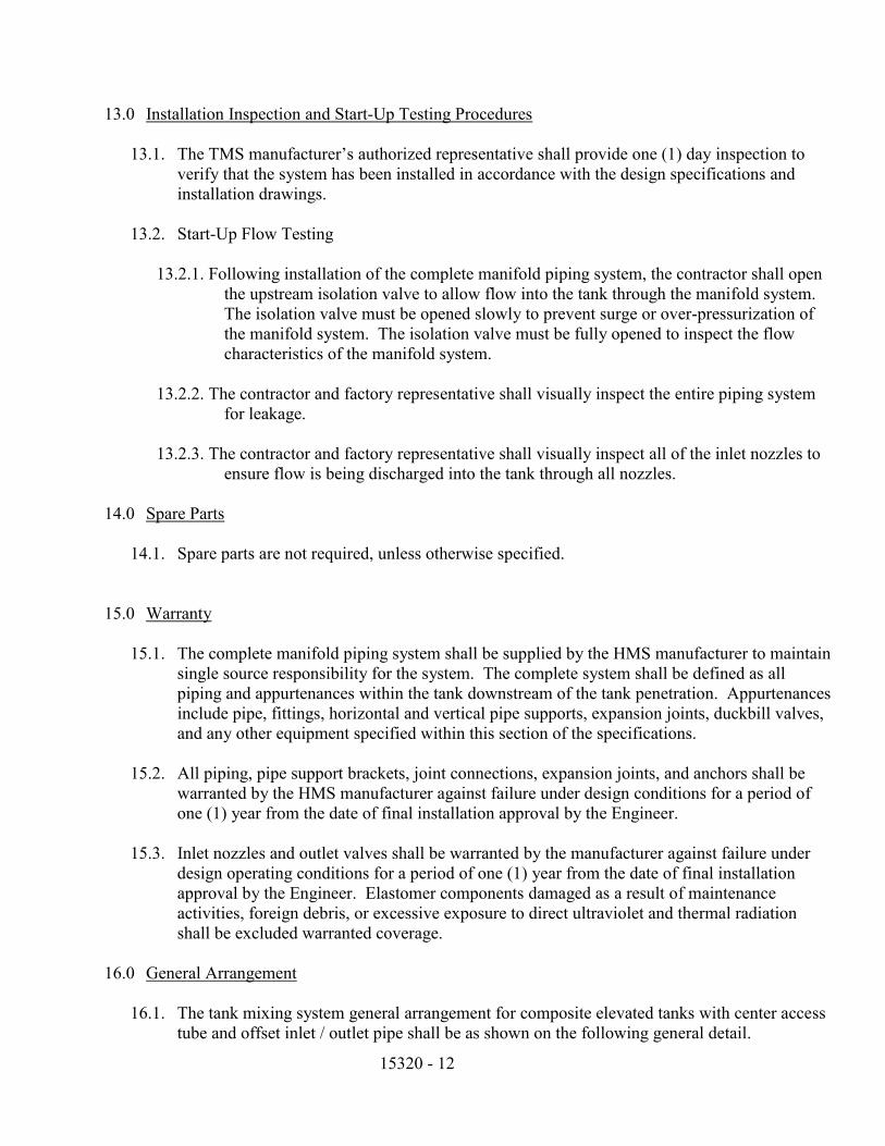
15320 - 12
13.0 Installation Inspection and Start-Up Testing Procedures
13.1. The TMS manufacturer’s authorized representative shall provide one (1) day inspection to verify that the system has been installed in accordance with the design specifications and installation drawings.
13.2. Start-Up Flow Testing
13.2.1. Following installation of the complete manifold piping system, the contractor shall open
the upstream isolation valve to allow flow into the tank through the manifold system. The isolation valve must be opened slowly to prevent surge or over-pressurization of the manifold system. The isolation valve must be fully opened to inspect the flow characteristics of the manifold system.
13.2.2. The contractor and factory representative shall visually inspect the entire piping system
for leakage.
13.2.3. The contractor and factory representative shall visually inspect all of the inlet nozzles to ensure flow is being discharged into the tank through all nozzles.
14.0 Spare Parts
14.1. Spare parts are not required, unless otherwise specified.
15.0 Warranty
15.1. The complete manifold piping system shall be supplied by the HMS manufacturer to maintain single source responsibility for the system. The complete system shall be defined as all piping and appurtenances within the tank downstream of the tank penetration. Appurtenances include pipe, fittings, horizontal and vertical pipe supports, expansion joints, duckbill valves, and any other equipment specified within this section of the specifications.
15.2. All piping, pipe support brackets, joint connections, expansion joints, and anchors shall be
warranted by the HMS manufacturer against failure under design conditions for a period of one (1) year from the date of final installation approval by the Engineer.
15.3. Inlet nozzles and outlet valves shall be warranted by the manufacturer against failure under
design operating conditions for a period of one (1) year from the date of final installation approval by the Engineer. Elastomer components damaged as a result of maintenance activities, foreign debris, or excessive exposure to direct ultraviolet and thermal radiation shall be excluded warranted coverage.
16.0 General Arrangement
16.1. The tank mixing system general arrangement for composite elevated tanks with center access tube and offset inlet / outlet pipe shall be as shown on the following general detail.

15320 - 13
End of Section

(This page left blank intentionally.)

ELECTRICAL SPECIFICATIONS FOR WATER SYSTEM IMPROVEMENTS 3,000,000 GALLON STORAGE TANK
MACON WATER AUTHORITY MACON, GEORGIA
Division Section Title Pages
DIVISION 1 - GENERAL REQUIREMENTS 01005 MAINTENANCE SPECIFICATIONS FOR ELECTRICAL CONTROLS 4 DIVISION 16 - ELECTRICAL 16010 BASIC ELECTRICAL REQUIREMENTS 2 16111 CONDUIT 4 16114 CABLE TRAYS 16123 BUILDING WIRE AND CABLE 3 16130 BOXES 2 16141 WIRING DEVICES 3 16160 TERMINAL BLOCKS AND ENCLOSURES 2 16170 GROUNDING AND BONDING 2 16180 EQUIPMENT WIRING SYSTEMS 1 16190 SUPPORTING DEVICES 2 16195 ELECTRICAL IDENTIFICATION 2 16420 ELECTRICAL SERVICES 1 16470 PANELBOARDS 2 16510 LUMINAIRES 4 16670 LIGHTNING PROTECTION FOR STRUCTURES 3 16902 ELECTRIC CONTROLS AND RELAYS 3 16914 GATE OPERATOR 4 16994 SCADA 5 16999 FIELD ACCEPTANCE TESTS 3 END OF TABLE OF CONTENTS

(This page left blank intentionally.)

16010 - 1
SECTION 16010 - BASIC ELECTRICAL REQUIREMENTS
PART 1 - GENERAL
1.1 SECTION INCLUDES
A. Basic Electrical Requirements specifically applicable to Division 16 Sections, in addition to Division 1 - General Requirements.
1.2 FUTURE WORK
A. Project is designed for future expansion of Division 16 systems.
1.3 REFERENCES
A. ANSI/NFPA 70 - National Electrical Code (2017).
B. IEEE - Institute of Electrical & Electronic Engineers.
1.4 SUBMITTALS
A. Submit under the following provisions:
1. Submittal Procedures:
a. Identify Project, Contractor and Subcontractor as appropriate. b. Apply Contractor's stamp, signed or initialed certifying that review, verification of
Products required, field dimensions, adjacent construction Work, and coordination of information, is in accordance with the requirements of the Work and Contract Documents.
c. Schedule submittals to expedite the Project, and deliver to Engineer at business address. Coordinate submission of related items.
d. Identify variations from Contract Documents and Product or system limitations which may be detrimental to successful performance of the completed Work.
e. Revise and resubmit submittals as required, identify all changes made since previous submittal.
f. Distribute copies of reviewed submittals to concerned parties. Instruct parties to promptly report any inability to comply with provisions.
2. Shop Drawings: Submit the number of opaque reproductions which Contractor requires, plus two copies which will be retained by Engineer.
3. Product Data:
a. Submit the number of copies which the Contractor requires, plus two copies which will be retained by the Engineer.
b. Mark each copy to identify applicable products, models, options, and other data. Supplement manufacturers' standard data to provide information unique to this Project.
B. Proposed Products List: Include Products specified in the following Sections:
1. Section 16111 - Conduit 2. Section 16114 - Cable Tray 3. Section 16123 - Building Wire and Cable

16010 - 2
4. Section 16141 - Wiring Devices 5. Section 16160 - Cabinets & Enclosures 6. Section 16170 - Grounding and Bonding 7. Section 16195 - Electrical Identification 8. Section 16470 - Panelboards 9. Section 16510 - Luminaires 10. Section 16670 - Lightning Protection Systems 11. Section 16902 - Electric Control and Relays 12. Section 16914 - Gate Operator 13. Section 16994 - SCADA 14. Section 16999 - Field Acceptance Tests
C. Submit shop drawings and product data grouped to include complete submittals of related systems, products, and accessories in a single submittal. Submittal shall be tabbed, indexed, and bound in a three ring binder.
D. Mark dimensions and values in units to match those specified.
1.5 REGULATORY REQUIREMENTS
A. Conform to applicable Building Code for Macon/Bibb County, Georgia.
B. Electrical: Conform to NFPA 70.
C. Obtain permits, and request inspections from authority having jurisdiction.
1.6 PROJECT/SITE CONDITIONS
A. Install Work in locations shown on Drawings, unless prevented by Project conditions.
B. Prepare drawings showing proposed rearrangement of Work to meet Project conditions, including changes to Work specified in other Sections. Obtain permission of Engineer before proceeding.
1.7 GUARANTEE AND TEST
A. Upon completion of the project all systems shall be tested for proper operation as directed by the Engineer or his representative. Equipment covers (i.e., motor controls, panelboards, etc.) shall be removed where required for inspection of internal wiring. The contractor shall furnish the personnel, tools and necessary equipment to inspect and test the system.
B. All systems and component parts shall be guaranteed for a period of one year from date of final acceptance of the complete project. Defects found during this guarantee period shall be promptly corrected at no additional cost to the Owner.
END OF SECTION 16010

16111 - 1
SECTION 16111 - CONDUIT
PART 1 - GENERAL
1.1 SECTION INCLUDES
A. Metal conduit.
B. Flexible metal conduit.
C. Liquidtight flexible metal conduit.
D. Fittings and conduit bodies.
1.2 RELATED SECTIONS
A. Section 16130 - Boxes.
B. Section 16170 - Grounding and Bonding.
C. Section 16190 - Supporting Devices.
1.3 REFERENCES
A. ANSI C80.1 - Rigid Steel Conduit, Zinc Coated.
B. ANSI/NEMA FB 1 - Fittings, Cast Metal Boxes, and Conduit Bodies for Conduit and Cable Assemblies.
C. ANSI/NFPA 70 - National Electrical Code.
D. NECA "Standard of Installation."
E. NEMA RN 1 - Polyvinyl Chloride (PVC) Externally Coated Galvanized Rigid Steel Conduit.
F. NEMA TC 2 - Electrical Plastic Tubing (EPT) and Conduit (EPC-40 and EPC-80).
G. NEMA TC 3 - PVC Fittings for Use with Rigid PVC Conduit and Tubing.
1.4 DESIGN REQUIREMENTS
A. Conduit Size: ANSI/NFPA 70.
1.5 SUBMITTALS
A. Submit under provisions of Section 16010.
B. Product Data: Provide for metallic conduit, flexible metal conduit, liquidtight flexible metal conduit, fittings and, conduit bodies.
1.6 PROJECT RECORD DOCUMENTS
A. Accurately record actual routing of underground conduits.

16111 - 2
1.7 REGULATORY REQUIREMENTS
A. Conform to requirements of ANSI/NFPA 70.
B. Furnish products listed and classified by Underwriters Laboratories, Inc. as suitable for purpose specified and shown.
1.8 DELIVERY, STORAGE, AND HANDLING
A. Accept conduit on site. Inspect for damage.
B. Protect conduit from corrosion and entrance of debris by storing above grade. Provide appropriate covering.
1.9 PROJECT CONDITIONS
A. Verify that field measurements are as shown on Drawings.
B. Verify routing and termination locations of conduit prior to rough-in.
C. Conduit routing is shown on Drawings in approximate locations unless dimensioned. Route as required to complete wiring system.
PART 2 - PRODUCTS
2.1 CONDUIT REQUIREMENTS
A. Minimum Size: 1/2-inch unless otherwise specified.
B. Underground and Underslab Installations: Use PVC coated rigid steel conduit, rigid steel conduit with asphaltic coating or concrete encased PVC conduit where conduit is routed underground.
C. Outdoor Locations, Above Grade: Use rigid steel conduit or intermediate metal conduit.
D. Wet and Damp Locations: Use PVC coated rigid steel conduit or intermediate metal.
E. Dry Locations: Exposed: Use rigid steel conduit, or intermediate metal conduit.
2.2 METAL CONDUIT
A. Rigid Steel Conduit: ANSI C80.1.
B. Intermediate Metal Conduit (IMC): Rigid steel.
C. Fittings and Conduit Bodies: ANSI/NEMA FB 1; material to match conduit.
2.3 NONMETALLIC CONDUIT
A. Description: NEMA TC2; Schedule 40 PVC, type DB.
B. Fittings and Conduit Bodies: NEMA TC3.

16111 - 3
2.4 PVC COATED METAL CONDUIT
A. Description: NEMA RN 1; rigid steel conduit with external PVC coating, 20 mil thick.
B. Fittings and Conduit Bodies: ANSI/NEMA FB 1; steel fittings with external PVC coating to match conduit.
2.5 FLEXIBLE METAL CONDUIT
A. Description: Interlocked steel construction.
B. Fittings: ANSI/NEMA FB 1.
2.6 LIQUIDTIGHT FLEXIBLE METAL CONDUIT
A. Description: Interlocked steel construction with PVC jacket.
B. Fittings: ANSI/NEMA FB 1.
2.7 ACCEPTABLE MANUFACTURERS
A. Acceptable manufacturers of conduit products specified herein are as follows: Allied, Triangle, Wheatland or Robroy.
PART 3 - EXECUTION
3.1 INSTALLATION
A. Install conduit in accordance with NECA "Standard of Installation."
B. Arrange supports to prevent misalignment during wiring installation.
C. Support conduit using materials as specified in Section 16190.
D. Do not support conduit with wire or perforated pipe straps. Remove wire used for temporary supports.
E. Arrange conduit to maintain headroom and present neat appearance.
F. Route exposed conduit parallel and perpendicular to walls.
G. Maintain adequate clearance between conduit and piping.
H. Cut conduit square using saw or pipecutter; de-burr cut ends.
I. Bring conduit to shoulder of fittings; fasten securely.
J. Use conduit hubs to fasten conduit to sheet metal boxes in damp and wet locations and to cast boxes.
K. Install no more than equivalent of four 90-degree bends between boxes. Use conduit bodies to make sharp changes in direction, as around beams. Use hydraulic one-shot bender to fabricate or factory elbows for bends in metal conduit larger than 2 inch size.

16111 - 4
L. Avoid moisture traps; provide junction box with drain fitting at low points in conduit system.
M. Provide suitable fittings to accommodate expansion and deflection where conduit crosses seismic, control and expansion joints.
N. Use "Push-Pennies" to protect installed conduit against entrance of dirt and moisture.
O. Ground and bond conduit under provisions of Section 16170.
P. Where connections to free-standing equipment in excess of 18" from structure are required, a vertical, minimum size 3/4", rigid conduit secured to ceiling and floor shall be utilized with wiring into this conduit by means of a rigid connection to a conduit body and wiring from this conduit by means of a conduit body with a flexible conduit connection to equipment.
Q. Flexible conduit shall not exceed 2'-0" in length unless specified otherwise.
3.2 INTERFACE WITH OTHER PRODUCTS
A. Install conduit to preserve watertight construction of elevated storage tank. Seal conduits in all electrical panels with clear silicon RTV adhesive. Also, seal all conduits which enter or exit the interior building space. Seal conduits and junction boxes airtight.
END OF SECTION 16111

SECTION 16114 - CABLE TRAYS
PART 1 - GENERAL
1.1 SECTION INCLUDES
A. Cable trays.
B. Cable tray accessories.
1.2 REFERENCES
A. NEMA FG 1 - Fiberglass Cable Tray Systems.
B. ASTM E-84 - (Class 1 rating).
1.3 SUBMITTALS
A. Submit product data under provisions of Section 16010.
B. Indicate tray type and dimensions.
PART 2 - PRODUCTS
2.1 LADDER-TYPE CABLE TRAYS
A. Tray: NEMA FG 1; Class C; 100 lb. per foot load rating on 20 foot span.
B. Material and Finish of Tray, Fittings, and Accessories: Fiberglass
C. Inside Width: As indicated, minimum 12 inch.
D. Inside Depth: 4 inches.
E. Straight Section Rung Spacing: 9 inches on center.
F. Inside Radii of Fittings: 12 inches.
G. Accessories and Fittings: Manufacturer's standard splice plates, reducer plates, blind ends, connectors and grounding straps. Provide fittings as required to complete tray system as shown on Drawings.
H. Manufacturers: Enduro, Husky, Legrand, Robroy or engineer approved equal.
PART 3 - EXECUTION
3.1 INSTALLATION
A. Installation: In conformance with NEMA FG 1 requirements and in accordance with manufacturer's instructions.

B. Support cable tray at each connection point, at the end of each run, and at other points to maintain spacing between supports of 12 ft maximum.
C. Cut standard straight sections to length in field.
D. Location of cable tray to be approved by Owner.
E. Provide a bare #6 AWG bonding conductor in each cable tray. Bonding conductor shall be continuous. Interconnect all associated metal supports, conduit, etc., with code bonding jumper and appropriate fittings and/or connectors.
END OF SECTION 16114

16123 - 1
SECTION 16123 - BUILDING WIRE AND CABLE
PART 1 - GENERAL
1.1 SECTION INCLUDES
A. Building wire and cable.
B. Wiring connectors and connections.
1.2 RELATED SECTIONS
A. Section 16111 - Conduit.
B. Section 16130 - Boxes.
C. Section 16195 - Identification.
1.3 REFERENCES
A. ANSI/NFPA 70 - National Electrical Code.
1.4 SUBMITTALS
A. Submit under provisions of Section 16010.
1.5 REGULATORY REQUIREMENTS
A. Conform to requirements of ANSI/NFPA 70.
B. Furnish products listed and classified by Underwriters Laboratories, Inc. suitable for purpose specified and shown.
1.6 PROJECT CONDITIONS
A. Verify that field measurements are as shown on Drawings.
B. All conductors shall be copper.
C. Routing shown on Drawings is approximate unless dimensioned. Route wire and cable as required to meet Project Conditions. Include wire and cable lengths within 10 feet of length shown.
D. Where routing is not shown, and destination only is indicated, determine exact routing and lengths required.
1.7 COORDINATION
A. Determine required separation between this and other work.
B. Determine routing to avoid interference with other work.

16123 - 2
PART 2 - PRODUCTS
2.1 MANUFACTURERS - BUILDING WIRE AND CABLE
A. Only product of domestic manufacturer will be accepted.
B. Manufacturers: Allied, Carol, Pirelli, Southwire or Triangle.
C. Substitutions: Engineer approved equals.
2.2 BUILDING WIRE
A. Description: Single conductor insulated wire.
B. Conductor: Copper no exceptions. Solid conductor for 10AWG and smaller; stranded for 8AWG and larger.
C. Insulation Voltage Rating: 600 volts.
D. Insulation: ANSI/NFPA 70; Type XHHW insulation for feeders and branch circuits 6AWG and larger; Type THHN/THWN insulation for feeders and branch circuits 8 AWG and smaller.
2.3 WIRING CONNECTORS
A. Solderless Pressure Connectors: 3M Skotch-loks or Ideal Wing Nut for 10 AWG and smaller
B. Compression Connectors: Burndy Hydent or Thomas and Betts, Color-Keyed for 8 AWG and larger.
C. Terminal Lugs: Thomas and Betts STA-KON for 10 AWG and smaller; Thomas and Betes Color-Keyed for 8 AWG and larger.
D. Seal connections in chlorine room with shrink tubing, airtight.
PART 3 - EXECUTION
3.1 EXAMINATION
A. Verify that mechanical work likely to damage wire has been completed.
B. PREPARATION
1. Completely and thoroughly swab raceway before installing wire.
C. WIRING METHODS
1. Use wiring methods indicated on Drawings.
D. INSTALLATION
1. Install products in accordance with manufacturers instructions. 2. Use conductor not smaller than 12 AWG for power and lighting circuits. 3. All control wiring shall be numbered on each end with Brady wire markers. 4. Pull all conductors into raceway at same time.

16123 - 3
5. Use suitable wire pulling lubricant for building wire 4 AWG and larger. 6. Protect exposed cable from damage. 7. Neatly train and lace wiring inside boxes, equipment, and panelboards. 8. Clean conductor surfaces before installing lugs and connectors. 9. Make splices, taps, and terminations to carry full ampacity of conductors with no
perceptible temperature rise. 10. Where compression connectors are used for conductor splices and taps; tape
uninsulated conductors and connector with electrical tape to 150 percent of insulation rating of conductor.
11. Use terminal lugs for connecting all stranded conductors and for all multiple connections to terminals.
3.2 INTERFACE WITH OTHER PRODUCTS
A. Identify wire and cable under provisions of Section 16195.
3.3 FIELD QUALITY CONTROL
A. Inspect wire for physical damage and proper connection.
B. Measure tightness of bolted connections and compare torque measurements with code recommended values.
C. Verify continuity of each branch circuit conductor.
END OF SECTION 16123


16130 - 1
SECTION 16130 - BOXES
PART 1 - GENERAL
1.1 SECTION INCLUDES
A. Pull and junction boxes
B. Outlet boxes
1.2 RELATED SECTIONS
A. Section 16141 - Wiring Devices: Mounting heights of wiring device outlets.
B. Section 16180 - Equipment Wiring Systems.
1.3 REFERENCES
A. ANSI/NEMA FB 1 - Fittings and Supports for Conduit and Cable Assemblies.
B. ANSI/NEMA OS 1 - Sheet-steel Outlet Boxes, Device Boxes, Covers, and Box Supports.
C. ANSI/NFPA 70 - National Electrical Code.
D. NEMA 250 - Enclosures for Electrical Equipment (1000 Volts Maximum).
1.4 REGULATORY REQUIREMENTS
A. Conform to requirements of ANSI/NFPA 70.
B. Furnish products listed and classified by Underwriters Laboratories, Inc. as suitable for purpose specified and shown.
1.5 PROJECT CONDITIONS
A. Verify field measurements are as shown on Drawings.
B. Electrical boxes are shown on Drawings in approximate locations unless dimensioned. Install at location required for box to serve intended purpose. Include installation within 10 feet of location shown.
PART 2 - PRODUCTS
2.1 OUTLET BOXES
A. Sheet Metal Boxes: ANSI/NEMA OS 1, galvanized steel.
B. Cast Boxes: NEMA FB 1, Type FD, cast feralloy. Provide gasketed cover by box manufacturer. Provide threaded hubs.
2.2 PULL AND JUNCTION BOXES
A. Cast Metal Boxes: NEMA OSI, cast metal with gasketed, screw-fastened cover.

16130 - 2
PART 3 - EXECUTION
3.1 INSTALLATION
A. Install electrical boxes as shown on Drawings, and as required for splices, taps, wire pulling, equipment connections and compliance with regulatory requirements.
B. Install electrical boxes to maintain headroom and to present neat mechanical appearance.
C. Align adjacent wall-mounted outlet boxes for switches, thermostats, and similar devices with each other.
D. Support boxes independently of conduit, except cast box that is connected to two rigid metal conduits both supported within 12 inches of box.
E. Use gang box where more than one device is mounted together. Do not use sectional box.
F. Use cast outlet boxes in exterior locations exposed to the weather.
G. Seal boxes in chlorine room airtight.
3.2 ADJUSTING
A. Install knockout closure or threaded plug in unused box opening.
END OF SECTION 16130

16141 - 1
SECTION 16141 - WIRING DEVICES
PART 1 - GENERAL
1.1 SECTION INCLUDES
A. Wall switches.
B. Receptacles.
1.2 RELATED SECTIONS
A. Section 16130 - Boxes.
1.3 REFERENCES
A. NEMA WD 1 - General Purpose Wiring Devices.
B. NEMA WD 6 - Wiring Device Configurations.
1.4 SUBMITTALS
A. Submit under provisions of Section 16010.
B. Product Data: Provide manufacturer's catalog information showing dimensions, colors, and configurations.
C. Manufacturer's Instructions:
1. Indicate application conditions and limitations of use stipulated by product testing agency specified under regulatory requirements.
2. Include instructions for storage, handling, protection, examination, preparation, operation and installation of product.
1.5 REGULATORY REQUIREMENTS
A. Conform to requirements of ANSI/NFPA 70.
B. Furnish products listed and classified by Underwriters Laboratories, Inc. as suitable for purpose specified and shown.
PART 2 - PRODUCTS
2.1 WALL SWITCHES
A. Manufacturers: Arrow-Hart, Hubbell, Leviton, Pass and Seymour or General Electric.
B. Description: NEMA WD 1, heavy-duty, AC only general-use snap switch.
C. Device Body: Ivory plastic with toggle handle.
D. Voltage Rating: 120 volts.
E. Current Rating: 20 amperes.

16141 - 2
2.2 RECEPTACLES
A. Manufacturers: Arrow-Hart, Hubbell, Leviton, General Electric or Pass and Seymour.
B. Description: NEMA WD 1; heavy-duty general-use receptacle.
C. Device Body: Ivory plastic.
D. Configuration: NEMA WD 6; type as specified or noted.
E. Convenience Receptacle: Type 5-20R.
F. Corrosion Resistant Convenience Receptacle: Hubbell #53CM62, or equal.
G. GFCI Receptacle: Convenience receptacle with integral ground fault circuit interrupter to meet regulatory requirements.
2.3 COVERPLATES
A. Weatherproof Coverplate: Gasketed cast metal with spring-hinged gasketed device cover.
B. Exposed Cover Plate: Galvanized steel.
C. Manufacturer: Mulberry or Pass and Seymour.
PART 3 - EXECUTION
3.1 EXAMINATION
A. Verify outlet boxes are installed at proper height.
B. Verify branch circuit wiring installation is completed, tested, and ready for connection to wiring devices.
3.2 PREPARATION
A. Clean debris from outlet boxes.
3.3 INSTALLATION
A. Install products in accordance with manufacturer's instructions.
B. Install devices plumb and level.
C. Install switches with OFF position down.
D. Install receptacles with grounding pole on top.
E. Connect wiring device grounding terminal to outlet box with bonding jumper.
F. Connect wiring devices by wrapping solid conductor around screw terminal; otherwise, utilize terminal lugs for connections. Do not "back wire" devices.
G. Install weatherproof cover plates on outlet boxes for outdoor locations.

16141 - 3
3.4 INTERFACE WITH OTHER PRODUCTS
A. Coordinate locations of outlet boxes provided under Section 16130 to obtain mounting heights specified and indicated on Drawings.
3.5 FIELD QUALITY CONTROL
A. Inspect each wiring device for defects.
B. Operate each wall switch with circuit energized and verify proper operation.
C. Verify that each receptacle device is energized.
D. Test each receptacle device for proper polarity.
E. Test each GFCI receptacle device for proper operation.
END OF SECTION 16141


16160 - 1
SECTION 16160 - TERMINAL BLOCKS AND ENCLOSURES
PART 1 - GENERAL
1.1 WORK INCLUDED
A. Hinged cover enclosures.
B. Terminal blocks and accessories.
1.2 RELATED SECTIONS
A. Section 16902 - Electric Controls and Relays: Pushbutton switches, selector switches and pilot devices.
1.3 REFERENCES
A. ANSI/NEMA ICS 1 - Industrial Control and Systems.
B. ANSI/NEMA ICS 4 - Terminal Blocks for Industrial Control Equipment and Systems.
C. ANSI/NEMA ICS 6 - Enclosures for Industrial Control Equipment and Systems.
1.4 SUBMITTALS
A. Submit product data under provisions of Section 16010.
PART 2 - PRODUCTS
2.1 HINGED COVER ENCLOSURES
A. Construction For Outdoor Installation: Type 4X, stainless steel.
B. Construction For Indoor Installation: NEMA Type 12, J.I.C.
C. Covers: Continuous hinge, held closed by flush latches operable by screwdriver.
D. Lockable, with padlock. Provide padlock and two sets of keys.
E. Panel for mounting terminal blocks, as applicable: 14 gauge steel, white enamel finish.
F. Manufacturers: Hoffman, Keystone, Robroy or Asco.
2.2 TERMINAL BLOCKS AND ACCESSORIES
A. Terminal Blocks: ANSI/NEMA ICS 4; UL listed.
B. Power Terminals: Channel mounted, unit construction closed-back type, with tubular pressure screw connectors, rated 600 volts, 40 amperes minimum.
2.3 FABRICATION
A. Shop assemble enclosures housing terminal blocks in accordance with ANSI/NEMA ICS 6.

16160 - 2
B. Provide WP conduit connectors, as required, on outdoor enclosures. Penetrate bottom of enclosure only.
C. Provide schematic diagram, connection diagram, and layout drawing of control wiring and components within each enclosure.
PART 3 - EXECUTION
3.1 INSTALLATION
A. Install enclosures as detailed on drawings; as a minimum, anchor securely to structural supports at each corner.
END OF SECTION 16160

16170 - 1
SECTION 16170 - GROUNDING AND BONDING
PART 1 - GENERAL
1.1 SECTION INCLUDES
A. Grounding electrodes and conductors.
B. Equipment grounding conductors.
C. Bonding.
1.2 REFERENCES
A. ANSI/NFPA 70 - National Electrical Code.
B. IEEE - Institute of Electrical & Electronic Engineers.
1.3 GROUNDING ELECTRODE SYSTEM
A. Ground the electrical service system neutral at service entrance equipment to metallic water service and to supplementary grounding electrodes.
B. Ground each separately-derived system neutral to separate grounding electrode.
C. Bond together system neutrals, service equipment enclosures, exposed non-current carrying metal parts of electrical equipment, metal raceway systems, grounding conductor in raceways and cables, receptacle ground connectors, and plumbing systems.
D. Provide a separate grounding conductor in all flexible conduits and nonmetallic conduit.
E. Connect wiring device grounding terminal to outlet box with bonding jumper.
F. Rod Electrode.
1.4 PERFORMANCE REQUIREMENTS
A. Grounding System Resistance: 5 ohms.
1.5 PROJECT RECORD DOCUMENTS
A. Accurately record actual locations of grounding electrodes.
1.6 REGULATORY REQUIREMENTS
A. Conform to requirements of ANSI/NFPA 70.
B. Furnish products listed and classified by Underwriters Laboratories, Inc. as suitable for purpose specified and shown.

16170 - 2
PART 2 - PRODUCTS
2.1 ROD ELECTRODE
A. Material: Copper-clad steel.
B. Diameter: 3/4 inch
C. Length: 10 feet
2.2 MECHANICAL CONNECTORS
A. Material: Bronze.
2.3 EXOTHERMIC CONNECTIONS
A. Manufacturers: Cadweld, or engineer approved equal.
2.4 WIRE
A. Material: Stranded copper.
B. Grounding Electrode Conductor: Size to meet NFPA 70 requirements.
PART 3 - EXECUTION
3.1 EXAMINATION
A. Verify that final backfill and compaction has been completed before driving rod electrodes.
3.2 INSTALLATION
A. Install Products in accordance with manufacturer's instructions.
B. Install rod electrodes at locations indicated. Install up to two (2) additional rod electrodes as required to achieve specified resistance to ground.
C. Connect grounding electrode conductors to metal water pipe using a suitable ground clamp. Make connections to flanged piping at street side of flange.
D. Provide grounding electrode conductor and connect to reinforcing steel in foundation footing where indicated.
E. Provide bonding to meet Regulatory Requirements.
3.3 FIELD QUALITY CONTROL
A. Inspect grounding and bonding system conductors and connections for tightness and proper installation.
B. Use suitable test instrument to measure resistance to ground of system. Perform testing in accordance with test instrument manufacturer's recommendations using the fall-of-potential method.

16170 - 3
3.4 GROUND RESISTANCE:
A. Test each ground rod in accordance with IEEE Std. 142 and submit tabulation of results to Engineer. Include identification of electrode, date of reading and ground resistance value in results.
B. Test each entire grounding system for continuity of connections and for resistance. Ensure that ground resistance of conduits, equipment cases, and supporting frames does not vary appreciably from that of system as whole and does not exceed 5 Ohms.
END OF SECTION 16170


16180 - 1
SECTION 16180 - EQUIPMENT WIRING SYSTEMS
PART 1 - GENERAL
1.1 WORK INCLUDED
A. Electrical connections to equipment specified under other Sections or furnished by Owner.
1.2 RELATED WORK
A. Section 16111 - Conduit.
B. Section 16123 - Wire and Cable.
C. Section 16130 - Boxes.
1.3 REFERENCES
A. NEMA WD 1 - General Purpose Wiring Devices.
PART 2 - PRODUCTS: NOT USED
PART 3 - EXECUTION
3.1 INSPECTION
A. Verify that equipment is ready for electrical connection, wiring, and energization.
3.2 PREPARATION
A. Review equipment submittals prior to installation and electrical rough-in. Verify location, size, and type of connections. Coordinate details of equipment connections with supplier and installer.
3.3 INSTALLATION
A. Use wire and cable with insulation suitable for temperatures encountered in heat-producing equipment.
B. Make connections to equipment as indicated on drawings.
C. Provide suitable strain-relief clamps for cord connections to equipment connection boxes.
D. Make wiring connections in control panel or in wiring compartment of pre-wired equipment in accordance with manufacturer's instructions. Provide interconnecting wiring where indicated.
E. Install disconnect switches, controllers, control stations, and control devices, etc. as indicated. Connect with wiring as indicated.
F. Do not make improper connections to equipment. Notify engineer of discrepancies.
END OF SECTION 16180


16190 - 1
SECTION 16190 - SUPPORTING DEVICES
PART 1 - GENERAL
1.1 WORK INCLUDED
A. Conduit and equipment supports.
B. Fastening hardware.
C. Plywood backboards
D. Housekeeping pads and curbs
1.2 QUALITY ASSURANCE
A. Support systems shall be adequate for weight of equipment and conduit, including wiring, which they carry.
1.3 RELATED SECTIONS
A. Section 16195 - Electrical Identification: Color coding of Equipment Backboards
PART 2 - PRODUCTS
2.1 MATERIAL
A. Support Channel: Galvanized steel angle iron.
B. Hardware: Stainless Steel.
C. Plywood: Exterior glue, type AC.
D. Concrete: 3000 psi at 28 days.
PART 3 - EXECUTION
3.1 INSTALLATION
A. Use toggle bolts in hollow masonry, plaster, or gypsum board partitions and walls; expansion anchors in solid masonry walls; or concrete surfaces; and sheet metal screws on plywood backboards.
B. Do not fasten supports to piping, ductwork, mechanical equipment, or conduit.
C. Do not use powder-actuated anchors.
D. Do not drill structural steel members.
E. Fabricate supports from structural steel or steel channel, rigidly welded or bolted to present a neat appearance. Use hexagon head bolts with spring lock washers under all nuts or double nuts jammed tight.
F. Install surface-mounted cabinets, panelboards, etc. with minimum of four anchors.

16190 - 2
G. Provide 3/4 inch plywood backboards with angle iron frame for all surface mounted equipment and as noted or specified.
H. Install free standing equipment atop concrete housekeeping pads, minimum 4 inches.
I. Provide concrete housekeeping curbs, minimum 4 inches, to surround exposed conduit below surface mounted equipment and backboards.
END OF SECTION 16190

16195 - 1
SECTION 16195 - ELECTRICAL IDENTIFICATION
PART 1 - GENERAL
1.1 WORK INCLUDED
A. Nameplates
B. Wire color coding
C. Conduit color coding
D. Equipment backboards color coding
E. Panelboard directories.
1.2 SUBMITTALS
A. Submit shop drawings under provisions of Section 16010.
B. Include schedule for nameplates.
PART 2 - PRODUCTS
2.1 MATERIALS
A. Nameplates: Engraved two-layer laminated plastic, black letters on a white background.
B. Tape: Vinyl plastic electrical tape.
C. Paint: Flat Enamel.
PART 3 - EXECUTION
3.1 INSTALLATION
A. Degrease and clean surfaces to receive nameplates
B. Install nameplates parallel to equipment lines.
C. Secure nameplates to equipment fronts using screws. Do not apply with adhesives.
3.2 WIRE IDENTIFICATION
A. For building wire and cables in sizes 8 AWG and smaller provide with factory insulation to correspond to color code; in sizes 6 AWG and larger provide 3/4" colored tape bands in lieu of colored insulation.
B. Color coding shall be as follows:
1. 120/240V System:
a. Phase A: Black b. Phase B: Red

16195 - 2
c. Neutral: White d. Ground: Green
3.3 NAMEPLATE ENGRAVING SCHEDULE
A. Provide nameplates to identify all electrical distribution and control equipment, and loads served.
B. Provide nameplates of minimum letter height as scheduled below.
1. Automatic transfer switch and panelboards: 1/4 inch; identify equipment designation. 1/8 inch; identify voltage rating.
2. Enclosed switches/circuit breakers, switchboard distribution breakers, and motor starters: 1/8 inch; identify load served.
3. Transformers: 1/4 inch; identify equipment designation. 1/8 inch; identify primary and secondary voltages.
3.4 PANELBOARD DIRECTORIES
A. For all panelboards, provide neatly typewritten directory of each device usage including building room numbers (e.g. Convenience Outlets Room A101).
B. Locate directory inside panelboard door. Protect directory with clear plastic.
3.5 BACKBOARD COLOR CODING SCHEDULE
A. Paint before fabrication, both sides with two coats enamel.
B. Electrical Equipment Backboards: Medium grey.
END OF SECTION 16195
16420 - 1
SECTION 16420 - ELECTRICAL SERVICES
PART 1 - GENERAL
1.1 WORK INCLUDED
A. Arrange with utility company for permanent electric service.
1.2 RELATED WORK
A. Section 16111 - Conduit.
1.3 SYSTEM DESCRIPTION
A. System Voltage: 240/120 volts, single phase, three wire, 60 Hertz (existing).
PART 2 - PRODUCTS
PART 3 - EXECUTION
3.1 INSTALLATION
A. Make arrangements with Utility Company to obtain permanent electric service. Contractor shall pay all costs.
END OF SECTION 16420


16470 - 1
SECTION 16470 - PANELBOARDS
PART 1 - GENERAL
1.1 RELATED DOCUMENTS
A. Drawings and general provisions of the Contract, including General and Supplementary Conditions and Division 1 Specification Sections, apply to this Section.
1.2 WORK INCLUDED
A. Panelboards and accessories.
1.3 RELATED SECTIONS
A. Section 16195 - Electrical Identification: Nameplates and directories.
1.4 REFERENCES
A. NEMA AB 1 - Molded Case Circuit Breakers.
B. NEMA PB 1 - Panelboards.
C. NEMA PB 1.1 - Instructions for Safe Installation, Operation and Maintenance of Panelboards Rated 600 Volts or Less.
1.5 SUBMITTALS
A. Submit shop drawings for equipment and component devices under provisions of Section 16010.
B. Include outline and support point dimensions, voltage, main bus ampacity, integrated short circuit ampere rating, circuit breaker arrangement and sizes.
1.6 SPARE PARTS
A. Keys: Furnish 2 each to Owner.
PART 2 - PRODUCTS
2.1 PANELBOARDS
A. Panelboards: NEMA PB1; circuit breaker type.
B. Enclosure: NEMA PB 1; Type 1, or as noted on drawings and panel schedule.
C. Provide flush or surface cabinet front as scheduled with screw cover and hinged door with flush lock all keyed alike. Finish in manufacturer's standard gray enamel.
D. Minimum Integrated Short Circuit Rating: 10,000 amperes rms symmetrical for 240 volt panelboards; unless noted otherwise on Drawings.
E. Molded Case Circuit Breakers: NEMA AB 1; bolt-on type thermal magnetic trip circuit breakers, with common trip handle for all poles. Circuit breakers shall be listed as suitable for use with 75C conductor.

16470 - 2
F. Acceptable Manufacturers: Square D, Cutler-Hammer/Westinghouse, General Electric or Siemens ITE.
PART 3 - EXECUTION
3.1 INSTALLATION
A. Install panelboards plumb in conformance with NEMA PB 1.1.
B. Top of Panel Height: Panelboards with box dimensions of 53 inches or less in height shall be installed with top of panel at 6 ft.-6 in. Panels with box dimensions in excess of 53 inches in height shall be installed such that the operating handle of the uppermost device is 72 inches above finished floor.
C. Provide filler plates for unused spaces in panelboards.
D. Provide nameplate and typed circuit directory in accordance with Section 16195 for each panelboard. Revise directory to reflect circuiting changes required to balance phase loads.
3.2 FIELD QUALITY CONTROL
A. Measure steady state load currents at each panelboard feeder. Should the difference at any panelboard between phases exceed 20 percent, rearrange circuits in the panelboard to balance the phase loads within 20 percent. Take care to maintain proper phasing for multi-wire branch circuits.
B. Visual and Mechanical Inspection: Inspect for physical damage, proper alignment, anchorage, and grounding. Check proper installation and tightness of connections for circuit breakers, and lugs.
END OF SECTION 16470

16510 - 1
SECTION 16510 - LUMINAIRES
PART 1 - GENERAL
1.1 RELATED DOCUMENTS
A. Drawings and general provisions of the Contract, including General and Supplementary Conditions and Division 1 Specification Sections, apply to this Section.
1.2 SECTION INCLUDES:
A. Interior and exterior luminaires.
B. Ballasts.
C. Lamps.
D. Luminaire accessories.
1.3 RELATED SECTIONS:
A. Section 16111 - Conduit.
B. Section 16130 - Boxes.
C. Section 16145 - Building Lighting Controls.
1.4 REFERENCES:
A. ANSI/IEEE C62.41 - 1991 - IEEE Recommended Practice on Surge Voltages in Low-Voltage AC Power Circuits.
B. ANSI/NFPA 70 - National Electrical Code.
1.5 SUBMITTALS:
A. Submit under provisions of Section 16010.
B. Product Data: Provide dimensions, ratings, and performance data.
1.6 OPERATION AND MAINTENANCE DATA:
A. Submit under provisions of Section 16010.
B. Maintenance Data: Include replacement parts list.
1.7 REGULATORY REQUIREMENTS:
A. Conform to requirements of ANSI/NFPA 70.
B. Furnish products listed and classified by Underwriters Laboratories, Inc. as suitable for purpose specified and shown.

16510 - 2
PART 2 - PRODUCTS
2.1 LUMINAIRES:
A. Furnish products as specified in schedule on Drawings.
B. Install ballasts, lamps, and accessories at factory.
2.2 BALLASTS:
A. Fluorescent Ballast: Provide ballast as applicable for lamp types as follows:
1. T-8 "Octron" Ballast:
a. High frequency, electronic, program-start, parallel wired type rated for full lumen output of lamp(s).
b. Light output shall remain constant for line voltage fluctuations of +5 percent minimum.
c. Ballast shall withstand line transients as defined in ANSI/IEEE C62.41, category A. d. Lamps shall operate at a frequency of 20 KHz or higher with no detectable flicker. e. Lamp current crest factor shall not exceed 1.7. f. Ballast shall have a power factor of 90 percent or above. g. Ballast shall not contain polychlorinated biphenyls (PCB's). h. Acceptable Manufactures: Advance, Triad or Osram-Sylvania.
2. T-5 "HO" Ballast: Similar to T8 Ballast above. 3. Sound ratings of "A" are required, unless specified otherwise. 4. UL listing of Class P thermal protection required. 5. Voltage: Match luminaire voltage as scheduled.
2.3 LAMPS:
A. Fluorescent Lamps:
1. T-8's: 4100 Kelvin, tri-phosphor. 2. T-5’s: 4100 Kelvin, tri-phosphor.
B. Provide lamp type specified for luminaire.
C. Acceptable Manufacturers: General Electric, Osram-Sylvania, Venture or Phillips.
2.4 LED LIGHT FIXTURES
A. General:
1. LED light fixtures shall be in accordance with IES, NFPA, UL, as shown on the drawings, and as specified.
2. LED light fixtures shall be Reduction of Hazardous Substances (RoHS)-compliant. 3. LED drivers shall include the following features unless otherwise indicated:
a. Minimum efficiency: 85% at full load. b. Minimum Operating Ambient Temperature: -20˚ C. (-4˚ F.) c. Input Voltage: 120 - 277V (±10%) at 60 Hz. d. Integral short circuit, open circuit, and overload protection. e. Power Factor: ≥ 0.95.

16510 - 3
f. Total Harmonic Distortion: ≤ 20%. g. Comply with FCC 47 CFR Part 15.
4. LED modules shall include the following features unless otherwise indicated:
a. Comply with IES LM-79 and LM-80 requirements. b. Minimum CRI 80 and color temperature 3000˚ K unless otherwise specified in
LIGHTING FIXTURE SCHEDULE. c. Minimum Rated Life: 50,000 hours per IES L70. d. Light output lumens as indicated in the LIGHTING FIXTURE SCHEDULE.
B. LED Troffers:
1. LED drivers, modules, and reflector shall be accessible, serviceable, and replaceable from below the ceiling.
2. Housing, LED driver, and LED module shall be products of the same manufacturer.
2.5 ACCESSORIES:
A. This contractor is responsible to verify ceiling system type and to order appropriate accessories required for ceiling system compatibility.
B. Lense: Where applicable, lense shall be pattern 12 .125 minimum overall thickness, full prism, Virgin Acrylic. Hogged prism lens are unacceptable.
PART 3 - EXECUTION
3.1 EXAMINATION
A. Examine substrate and supporting grids for luminaires.
B. Examine each luminaire to determine suitability for lamps specified.
3.2 INSTALLATION
A. Install in accordance with manufacturers instructions.
B. Locate recessed ceiling luminaires as indicated on architectural reflected ceiling plan.
C. Install surface mounted luminaires plumb and adjust to align with building lines and with each other. Secure to prohibit movement.
D. Provide hanger wire from structure to each corner of fixture.
E. Install clips to secure recessed grid-supported luminaires in place.
F. Install wall mounted luminaires, at height as indicated on drawings or fixture schedule.
G. Install accessories furnished with each luminaire.
H. Make wiring connections to branch circuit using building wire with insulation suitable for temperature conditions within luminaire.
I. Bond products and metal accessories to branch circuit equipment grounding conductor where applicable.

16510 - 4
J. Install specified lamps in each luminaire.
3.3 FIELD QUALITY CONTROL:
A. Operate each luminaire after installation and connection. Inspect for proper connection and operation.
3.4 ADJUSTING:
A. Relamp luminaires that have failed lamps prior to Owner's acceptance.
3.5 CLEANING:
A. Clean electrical parts to remove conductive and deleterious materials.
B. Remove dirt and debris from enclosure.
C. Clean photometric control surfaces as recommended by manufacturer.
D. Clean finishes and touch up damage.
END OF SECTION 16510

SECTION 16670 - LIGHTNING PROTECTION FOR STRUCTURES
PART 1 - GENERAL
1.1 RELATED DOCUMENTS
A. Drawings and general provisions of the Contract, including General and Supplementary Conditions and Division 1 Specification Sections, apply to this Section.
1.2 SUMMARY
A. Section Includes
1. This Section specifies the lightning protection system for buildings and structures greater than 75 feet in height.
2. Provide all labor, materials, and equipment as necessary to complete all work as speci-fied herein.
3. The Contractor shall furnish and install a complete lightning protection system with all necessary components for a complete system.
B. Related Sections:
1. Section 16170 - Grounding and Bonding 2. Applicable sections of Division 16 - Electrical
1.3 SYSTEM DESCRIPTION
A. The entire lightning protection system shall be manufactured and installed in accordance with Underwriters Laboratories, Inc. Pamphlet no. UL96A Master Labeled Lightning Protection Systems.
B. Down conductor cable shall be surface mounted on outside of water tank. Provide two down conductors on opposite sides of tank/structure.
1.4 SUBMITTALS
A. Provide a complete design submittal including shop drawings showing the type, size and location of all grounding, roof conductors, down conductors, through roof connectors and air terminals.
1.5 QUALITY ASSURANCE
A. Upon completion the Contractor shall furnish the Owner with the standard UL Inspection certificate.
B. Installation of systems shall be performed by fully qualified personnel having had a minimum of ten years experience installing these types of systems. They shall have been certified for installation by a recognized lightning protection organization such as the Lightning Protection Institute and recognized by Underwriters Laboratories as a Lightning Protection System installer.

C. The design of the systems shall be performed by fully qualified personnel having had a minimum of five years experience on designing these types of systems. They shall have been certified for design by a recognized lightning protection school such as the Lightning Protection Institute.
PART 2 - PRODUCTS
2.1 STANDARD
A. All materials shall comply in weight size, and composition with the following requirements based on the type of building or structure involved.
1. National Fire Protection Association 780 2. Underwriters Laboratories 96
2.2 MANUFACTURERS
A. Acceptable manufacturers:
1. East Coast Lightning Equipment, Inc., Winsted, CT 2. Harger Lightning Protection, Inc., Grayslake, IL 3. National Lightning Protection, Denver, CO
2.3 MATERIALS
A. All materials for this installation shall be Class I as defined by Underwriters Laboratories Inc. for use on structures more than 75 feet in height.
B. Copper shall be of the grade ordinarily required for commercial electrical work, generally designated as being 98 percent conductivity when annealed.
C. Air Terminals
1. Roof Air Terminals: Solid copper having a minimum diameter of 3/4 inch and a length of not less than 12 inches or more than 24 inches with blunt tip. Wherever materials come in direct contact with aluminum surfaces, the air terminals shall be solid aluminum, ¾ inch in diameter.
D. Conductors:
1. Main Conductors – Copper Cable:
a. Copper weighing not less than 187 lbs per 1000 feet. b. The size of any wire in the conductor not less than No. 17 AWG. c. Minimum cross-sectional area of 57,400 cir. mil.
2. Bonding Conductors – Copper Cable:
a. The size of any wire in the conductor not less than No. 17 AWG. b. Minimum cross-sectional area of 26,240 cir. mil.

E. Attachments: Fasteners shall be of suitable configuration for the intended application and of the same material as the conductor. Nails, screws, or bolts employed to secure the fasteners shall be of the same material as the fasteners or of material which is as resistant to corrosion as that of the fasteners. (Galvanized or plated steel nails, screws, or bolts are not acceptable).
F. Connections and Splices: Connectors and splices shall be of suitable configuration and type for the intended application and of the same material as the conductor.
G. Ground Rod Electrodes: Copper-clad steel ground rods; 3/4-inch minimum diameter, 10'-0" long.
H. Use main conductor direct buried 24” below grade for ground loop around building.
I. Make connection to electrical service (2) grounds.
J. All underground connections shall be thermoweld type.
K. General: Bond all metal appurtenances within six feet of lightning conductor with pressure connection bond plate.
PART 3 - EXECUTION
3.1 STANDARD
A. The installation shall comply in manner, design, and detail with the following requirements based on the type of building or structure involved.
1. Lightning Protection Institute 175 Standard 2. Underwriters Laboratories 96A - Lightning Protection Components. 3. ANSI NFPA 780 - Standard for the Installation of Lightning Protection Systems.
3.2 INSTALLERS
A. Acceptable installers:
1. Atlanta Lightning Protection Inc., (404) 329-8700 2. Lightning Systems Inc., (770) 978-2028 3. Vickery Lightning Protection, (770) 466-6910
3.3 INSTALLATION
A. Install the Lightning Protection System as required to obtain UL Inspection Certificate. Upon completion of work contractor shall furnish the Inspection Certificate to owner.
END OF SECTION 16670


16902 - 1
SECTION 16902 - ELECTRIC CONTROLS AND RELAYS
PART 1 - GENERAL
1.1 SECTION INCLUDES
A. Pushbutton, selector switches and pilot devices.
B. Relays and sockets.
C. Current transformer, ammeter, alarm horn and strobe
1.2 RELATED SECTIONS
A. Section 16160 - Terminal Blocks and Enclosures
B. Section 16480 - Motor Control
1.3 REFERENCES
A. NEMA ICS 1 - General Standards for Industrial Control Systems.
B. NEMA ICS 2 - Standards for Industrial Control Devices, Controllers and Assemblies.
1.4 SUBMITTALS
A. Submit product data under provisions of Section 16010.
B. Submit product data for each component specified.
1.5 PROJECT RECORD DOCUMENTS
A. Accurately record actual locations of control equipment. Revise schematic diagrams shown on Drawings to reflect actual control connections.
1.6 OPERATION AND MAINTENANCE DATA
A. Submit maintenance data as follows:
1. Include recommended preventive maintenance procedures and materials.
PART 2 - PRODUCTS
2.1 CONTROL SWITCHES AND STATIONS
A. Pushbutton Operator: NEMA ICS2; heavy-duty, oiltight, watertight operator with full guard (Square D #9001 KR1UH13, or equal).
B. Pilot Lights: Transformer base pilot devices with 9 volt lamp. Lens color as specified (Square D #9001 KP1, or equal).
C. Selector Switches: NEMA ICS2; heavy-duty, oiltight, watertight 2 or 3 position selector switch, as applicable, with gloved hand "black" knob.

16902 - 2
1. Two Position Selector: Square D #9001 KS11FBH13 or equal. 2. "HOA" Selector: Square D #9001 KS43FBH13 or equal.
2.2 CONTROL RELAYS
A. General Purpose Control Relay with tube type termination for plug-in sockets (Square D #8501 Type KP).
1. Contact Ratings: 10 amperes nominal current rating, 2 or 3PDT, as required. 2. Coil Voltage: 120 volts AC, 60 Hz, continuous duty rated.
B. Sockets: 8 pin Octal, double tier, screw terminal sockets (Square D #8501 NR-52).
C. General Purpose "OFF" Delay Timing Relay with tube-type termination for plug-in sockets (Square D #9050 JCK25V2O) 1.8 to 180 seconds. Contacts and coil same as 2.2A.
1. Socket: 11 pin tubular, double tier, screw terminal socket (Square D #8501 NR62).
2.3 CURRENT TRANSFORMER
A. Mount in starter enclosure.
1. Square D #42102NR 500:5 ratio.
2.4 AMMETER DISPLAY
A. 0 - 500 amp display, input 0 - 5 amps, 4.5 inch square.
1. GE #25044OLSPZ (EIL Meters phone number 708-430-2292). 0 - 500 scale, labeled "Amps".
B. ALARM STROBE
1. 850 effective candle power, 78 flash per minute, high intensity strobe light (Federal Signal #27XST series B, 120 VAC).
C. ALARM HORN
1. 80 dB, NEMA 3R enclosure, 120 VAC.
D. ENCLOSURES
1. Pump Control Panel Enclosure: Steel with a lockable door.
E. FABRICATION
1. Control Panels: Shop fabricate control panels to NEMA ICS 1, using terminal blocks furnished under the provisions of Section 16160.
PART 3 - EXECUTION
3.1 INSTALLATION
A. Install devices and equipment in accordance with manufacturer's instructions.

16902 - 3
B. Install enclosures under the provisions of Section 16160.
END OF SECTION 16902


16914 - 1
SECTION 16914 - GATE OPERATOR
PART 1 - GENERAL
1.1 SECTION INCLUDES
A. Pre-wired, self-contained, slide gate operator for horizontal sliding gates, including all selected attachments and accessory equipment.
B. For further information, call the factory at 1-800-321-9947.
1.2 Submittals
A. Shop drawings: Submit shop drawings under the provisions of Section 06010. Submit drawings showing connections to adjacent construction, range of travel, and all electrical and mechanical connections to the operator. Drawings shall also show the size and location of the concrete mounting pad. Underground electrical runs shall be shown on shop drawings.
B. Installation instructions: Submit two copies of manufacturer's installation instructions for this specific project.
C. Test reports
1. Submit affidavits from the manufacturer demonstrating that the gate mechanism has been tested to 200,000 cycles without breakdown.
2. Each operator shall bear a label indicating that the operator mechanism has been tested for full power and pressure of all hydraulic components, full stress tests of all mechanical components and electrical tests of all overload devices.
1.3 QUALITY ASSURANCE
A. Manufacturer: A company specializing in the manufacture of hydraulic gate operators of the type specified, with a minimum of ten years experience.
B. Installer: A minimum of three years experience installing similar equipment.
1.4 CODES AND REGULATORY REQUIREMENTS
A. Operators shall be built to UL325 standards and be listed by a NRTL testing laboratory. Complete all electrical work according to local codes and National Electrical code. All fieldwork shall be performed in a neat and professional manner, completed to journeyman standards.
B. Current safety standards require the use of multiple external sensors to be capable of reversing the gate in either direction upon sensing an obstruction. See also 2.02D.
C. Vehicle gates should never be used by pedestrians. Separate pedestrian gates must always be provided when foot traffic is present.
D. Current safety standards require gate operators to be designed and labeled for specific usage classes. Hy-Security Model 222 SS-ST is compliant in all usage classes, Classes I-IV.

16914 - 2
1.5 PRODUCT DELIVERY AND STORAGE
A. Store products upright in the original containers, covered, ventilated and protected from all the weather condition.
1.6 WARRANTY
A. Provide a five-year limited warranty against all defects in materials or workmanship. Defective materials shall be replaced with comparable materials furnished by the manufacturer, at no cost to the owner. Freight, labor and other incidental costs are not covered under the factory warranty, but may be covered by a separate service agreement between installing company and the owner.
PART 2 - PRODUCTS
2.1 GATE OPERATORS
A. Hy-Security Gate Operators Model 222 SS-ST with Smart Touch Controller, or other comparable operator, as approved by the engineer. Substitute operators that are approved will be published in an addendum, not less than ten days prior to bid opening. Requests for substitution will include the amount of savings to be passed on to the owner.
2.2 OPERATION
A. Operation shall be by means of a metal rail passing between a pair of hydraulically driven solid metal wheels with polyurethane treads. Operator motors shall be hydraulic, geroller type, and system shall not include belts, gears, pulleys, roller chains or sprockets to transfer power from operator to gate panel. The operator shall generate a minimum horizontal pull of 300 pounds without the drive wheels slipping and without distortion of supporting arms. Operator shall be capable of handling gates weighing up to 1000 pounds. Gate panel velocity shall not be less than 1.0 feet per second and shall be stopped gradually to prevent shock loads to the gate and operator assembly.
B. Standard mechanical components shall include as a minimum:
1. Supporting arms: Cast aluminum channel. Arms shall incorporate a fully bushed, 1-1/2" bronze bearing surface, acting on arm pivot pins. (item 2 below)
2. Arm pivot pins: 3/4" diameter, stainless steel, with integral tabs for ease of removal. 3. Tension spring: 2-1/2" heavy duty, 800 pound capacity. 4. Tension adjustment: Finger tightened nut, not requiring the use of tools. 5. Drive Release: Must instantly release tension on both drive wheels, and disengage them
from contact with drive rail in a single motion, for manual operation. 6. Limit switches: Fully adjustable, toggle types. 7. Electrical enclosure: Oversized, metal, with hinged lid gasketed for protection from
intrusion of foreign objects, and providing ample space for the addition of accessories. 8. Chassis: 1/4" steel base plate, and 10 Ga. sides and back welded and ground smooth. 9. Cover: 16GA. galvanized sheet metal with a powder paint finish. All joints welded, filled
and ground smooth. Finished corners square and true with no visible joints. 10. Finish: Fully zinc plated then finish coat of high gloss powder paint withstanding 1000-
hour salt spray test. 11. Drive wheels: 6" Dia. Metal hub with polyurethane tread. 12. Drive rail: Shall be extruded 6061 T6, not less than 1/8" thick. Drive rail shall incorporate
alignment pins for ease of replacement or splicing. Pins shall enable a perfect butt splice.

16914 - 3
13. Hydraulic hose: Shall be 1/4" synthetic, rated to 2750 p.s.i. 14. Hydraulic valves: Shall be individually replaceable cartridge type, in an integrated
hydraulic manifold. 15. Hose fittings: At manifold shall be quick-disconnect type, others shall be swivel type. 16. Hydraulic fluid: High performance type with a viscosity index greater than 375. 17. A zero to 2000-PSI pressure gauge, mounted on the manifold for diagnostics, shall be a
standard component. 18. The hydraulic fluid reservoir shall be formed from a single piece of metal, non-welded,
and shall be powder painted on the inside and the outside, to prevent fluid contamination.
C. Minimum standard electrical components:
1. Pump motor: Shall be a 1 HP, 56C, TEFC, continuous duty motor, with a service factor of 1.15, or greater. Standard voltages available, single or three phase.
2. All components shall have overload protection. 3. Controls: Smart Touch Controller Board with 128K memory containing:
a. inherent entrapment sensor b. built in “warn before operate” system c. built in timer to close d. liquid crystal display for reporting of functions e. 19 programmable output relay options f. anti-tailgate mode g. built-in power surge/lightening strike protection h. capable, with optional software, of event logging EEPROM for trouble shooting
diagnostics i. RS232 port for connection to laptop or other computer peripheral and RS485
connection of Master/Slave systems
4. Transformer: 75 VA, non-jumpered taps, for all common voltages 5. Control circuit: 24VDC
D. Required external sensors: Gate edges to be installed such that the gate is capable of reversing in either direction upon sensing an obstruction.
E. Optional control devices: Pushbuttons
F. Voltage: 480 VAC three phase
2.3 FACTORY TESTING
A. Fully assemble and test, at the factory, each gate operator to assure smooth operation, sequencing and electrical connection integrity. Apply physical loads to the operator to simulate field conditions. Tests shall simulate physical and electrical loads equal to the fully rated capacity of the operator components.
B. Check all mechanical connections for tightness and alignment. Check all welds for completeness and continuity. Check welded corners and edges to assure they are square and straight.
C. Inspect painted finish for completeness and gloss. Touch up imperfections prior to shipment.
D. Check all hydraulic hoses and electrical wires to assure that chafing cannot occur during shipping or operation.

16914 - 4
PART 3 - EXECUTION
3.1 SITE EXAMINATION
A. Locate concrete mounting pad in accordance with approved shop drawings.
B. Make sure that gate is operating smoothly under manual conditions before installation of gate operators. Do not proceed until gate panel is aligned and operates without binding.
3.2 INSTALLATION
A. Install gate operator in accordance with the manufacturer's printed instructions, current at the time of installation. Coordinate locations of operators with contract drawings, other trades and shop drawings.
B. Installer shall insure that the electric service to the operator is at least 20 AMPS. Operator wattage is 1500.
3.3 FIELD QUALITY CONTROL
A. Test gate operator through ten full cycles and adjust for operation without binding, scraping or uneven motion. Test limit switches for proper "at rest" gate position.
B. All anchor bolts shall be fully concealed in the finished installation.
3.4 CONTINUED SERVICE AND DOCUMENTATION
A. Train owner's personnel in the general maintenance of the gate operator and accessories and provide one copy of "operations and maintenance", manual for the owner's use (a second manual is available upon request.) Manuals will identify parts of the equipment for future procurement.
END OF SECTION 16914

16994 - 1
SECTION 16994 - SCADA
PART 1 - GENERAL
1.1 SCOPE OF WORK
A. The Contractor shall install, program and wire final connections to an existing integrated telemetry and control system. The system shall include all modifications to the Master Telemetry Unit and all HMIs attached. This includes the addition of any new display screens and reports required to support the RTU and its functions within the system. Complete hydraulic/electrical diagrams, dimensional drawings, and functional description shall be provided for approval by the Engineer.
B. New RTU shall be used to monitor inputs and send outputs as required by the design of the system. These I/O points shall be transmitted to the Master Telemetry Unit and made available for display and storage on the Master PCs HMI system. The RTU currently is in use and shall remain operational during construction.
PART 2 - PRODUCTS
2.1 MANUFACTURER
A. The existing control equipment is Allen-Bradley. Control equipment shall be integrated by MR Systems, Inc. - phone 770-519-1299; Tom Hopkins.
B. Modifications to Existing SCADA System Application:
1. Additions and modifications shall be made to the existing SCADA system to incorporate the signals identified above into 3D graphics displays, reports, trends, and alarming functions.
2. The existing radio hub/repeater system shall be modified to accommodate the new water storage tank. Perform all PLC programming required to convey the I/O collected at the new water storage tank through the repeater system and to the Amerson water treatment plant SCADA application.
3. Coordinate all modifications to the existing SCADA system with the Owner prior to installation.
4. All modifications to the existing SCADA system shall be performed by M/R Systems, Inc. of Norcross, Georgia.
2.2 OPEN SYSTEM
A. Communications between the RTU and the Master Telemetry Unit shall support at least three (3) industry standard off-the-shelf serial communications protocols. These protocols shall be industry standard implementations of the Modbus ASCII Mode, Modbus RTU Mode, and Allen Bradley DF1 protocols. The Master Telemetry Unit is capable of examining and modifying, where appropriate, the status of digital inputs/outputs.
B. Each communications port shall be independently configurable for data rate, parity, protocol and address.
C. RTU Components: Existing and new.
D. Analog Input / Output Protection: The RTU shall be protected from high voltage surges on all analog inputs and outputs by 24 VDC multistage hybrid surge protectors.

16994 - 2
2.3 RTU COMPONENTS
A. The following components shall be included in the RTU:
1. Local Control Unit: It shall process all inputs and outputs and handle all communications with the Master Telemetry Unit via the data radio.
2. Radio / Modem Transceiver: It shall be of industrial grade with diagnostics and be compliant with 12.5 KHz channel bandwidth in the VHF or UHF frequency range. It shall also be capable of “over the air” transmission rates of 4800 and 9600 bps.
3. Control Breaker: It shall be mounted on the enclosure backplate and provide easy access to interrupt power to the RTU as required for service.
4. Power Supply Module: It shall support input line voltage of 120 VAC and provide up to 14 VDC output with a minimum of 75-Watt capacity.
5. AC Line Surge Protector: It shall protect the RTU from high voltage surges on the AC Power by a multistage hybrid surge protector.
6. Antenna Surge Protector: It shall protect the RTU from high voltage surges at the antenna by direct short to ground via gas tube.
7. Digital Input / Output Protection: The RTU shall be protected from high voltage surges on all digital inputs and outputs by socket mounted relays.
8. Analog Input / Output Protection: The RTU shall be protected from high voltage surges on all analog inputs and outputs by 24 VDC multistage hybrid surge protectors.
9. Battery Backup: The RTU shall contain a sealed lead acid battery charged by the DC Power supply, to provide uninterrupted power during normal outages of the 120 VAC utility power.
10. Enclosure: The enclosure shall be stainless steel with a NEMA 4x rating. All hardware shall be stainless steel and have a lockable hasp. The door gasket shall be continuous. All penetrations shall be from the bottom to prevent leakage from rain.
2.4 ANTENNA
A. The radio telemetry system supplier shall provide an antenna as required to achieve the overall communications requirements of the system. The antenna shall be directional or omni-directional as determined by the Radio Path Study and be suitable for outdoor environments. It shall be of aluminum construction and mounted to withstand as least 100-MPH winds with ½ inch radial ice. It is the Owner’s intent to improve long term communications reliability by improving the received signal strength where possible.
B. The Control System Integrator shall provide 7/8” (LDF5) Heliax antenna cable. Provide and install 7/8”A Type N connectors, 7/8” grounding straps (2) and cable/connector weatherproofing kits as required.
C. The Control System Integrator shall supply and install a new RF surge protector enclosure comprised of a Phoenix Contact CoaxTrab RF Surge Protector mounted in a polycarbonate enclosure. The new RF surge protector enclosure shall be installed in the coaxial cable immediately prior to the cable’s entry to the existing RTU enclosure. The Control System Integrator shall install additional ground wiring as required.
D. The Control System Integrator shall supply and install a new Bluewave 16.5 dB gain Yagi antenna.

16994 - 3
2.5 HEATED LEVEL INDICATING TRANSMITTER ENCLOSURE(S)
A. The Control System Integrator shall provide redundant Rosemount 3051CG level indicating transmitters mounted in a NEMA 4X, stainless steel enclosures with heater, thermostat, drain/breather plug, and heat trace tape. At the Owner’s option the two level transmitters may be housed in a single NEMA 4X stainless steel enclosure.
B. Each level indicating transmitter shall be Rosemount Model 3051CG4A22A1AB4M5 with integral LCD display, HART communications, and universal mounting bracket.
C. Each tank level transmitter enclosure shall be Hoffman, NEMA 4X stainless steel. Size of enclosure shall be approximately 16” high by 14” wide by 12” deep with subpanel.
D. Internal to each tank level transmitter enclosure provide a 10 amp circuit breaker to provide branch circuit protection for the heat trace tape circuit.
E. Provide an analog surge protector integral to each tank level transmitter enclosure to protect the output signal of the level indicating transmitter. Analog surge protector shall provide three separate levels of surge/transient suppression. The first level of protection shall be via a 1/4 Amp 3AG size fast acting fuse. Secondary and tertiary protection shall be fulfilled using combination gas discharge and metallic oxide varistor (MOV) surge protection with current limiting resistors. Analog surge protector shall be the Kamikaze ASA-2 analog surge arrestor as developed by M/R Systems, Inc. and as manufactured by Phoenix Contact.
F. Provide heat trace tape as required to protect the pressure sensing line from the tank to the Heated Level Indicating Transmitter Enclosure
G. Provide drain/breather plug in bottom of enclosure to provide protection for the transmitter in the event of pressure sensing line leak.
2.6 INPUTS AND OUTPUTS
A. Digital Inputs (23)
1. Door Alarm (Intrusion) 2. Power Failure 3. 4 Spare
B. Digital Outputs (9)
1. Major alarm 2. Minor alarm 3. 4 Spare
C. Analog Inputs (16)
1. Detention Pond Level 1 2. Detention Pond Level 2 3. Storage Tank Level (2) 4. 2 Spare
D. Analog Outputs
1. Setpoint to Town Creek Water Treatment Plant

16994 - 4
PART 3 - EXECUTION
3.1 SERVICE
A. The contractor shall provide the services of a factory trained representative to check the completed installation, place the equipment in operation and instruct the owner’s personnel in the proper use and maintenance of the equipment.
3.2 RADIO SYSTEM
A. Central radio system is existing.
B. Radio Path Study: The telemetry system manufacturer shall provide all radio path surveys and design the system for 99.9% reliability with at least a 15dB fade margin above the minimum sensitivity of the radio equipment.
3.3 ANTENNA MOUNTING
A. The antenna shall be mounted to a mast and wood pole, as specified herein, which shall be suitable for outdoor environmental conditions, provide adequate support and protection for the antenna and coaxial line and allow for the antenna to be mounted at the height and oriented in the direction as determined by the Radio Path Study.
B. Top of water tank antenna shall be secured to provisions provided by tank manufacturer.
3.4 WOOD POLES
A. Poles shall be pressure-treated southern pine of the length and class indicated. It shall be turned smooth full length and be roofed prior to pressure treatment.
B. Poles shall be set six (6) feet in the ground. Holes shall be dug large enough to permit the proper use of tampers to the full depth of the hole. Earth shall be thrown into the hole in six (6) inch maximum layers, then thoroughly tamped before the next layer is thrown in. Surplus earth shall be placed around the pole in a conical shape and packed tightly to drain water away from pole.
3.5 TRAINING
A. The supplier shall offer regularly scheduled software training classes, open to everyone, for the purpose of teaching how to program all equipment furnished.
3.6 CONTROL EQUIPMENT
A. Install according to manufacturer’s instruction and in accordance with plans and specifications.
3.7 GUARANTEE
A. The manufacturer shall provide an unconditional guarantee on the equipment for a period on one year after acceptance by the Engineer regardless of shipping time. The guarantee shall include all labor, parts, travel and expenses necessary for detecting and correcting any problem which prevents satisfactory operation.

16994 - 5
B. Lightning and other surges: All surge protection devices have a dual function.
1. For normal lightning and power surges, the surge protection devices will protect the RTU and continue operation with no need for replacement.
2. For direct lightning strikes and extreme power surges, the surge protection devices will “self-destruct” in every effort to protect the RTU.
C. For the purposes of this guarantee, “self-destruction” is determined by the evidence of “burned and cracked surge protection device shells” or “burn marks on the enclosure backplane in the vicinity of the surge protection device.”
D. In the event of RTU failure when evidence of “self-destruction” IS found, the device is considered to have performed in its designed manner. All equipment found non-functional in the RTU enclosure will not be replaced under this guarantee.
E. In the event of RTU failure when evidence of “self-destruction” IS NOT found, all equipment found non-functional in the RTU enclosure shall be replaced under this guarantee.
END OF SECTION 16994


16999 - 1
SECTION 16999 - FIELD ACCEPTANCE TESTS
PART 1 - GENERAL
1.1 DESCRIPTION:
A. After electrical installation is complete, perform tests to demonstrate that entire system is in proper working order and in accordance with drawings and specifications. Do not perform tests less than those outlined hereafter, unless requested in writing and approved by the Owner. Tests are in addition to, and no substitution for, tests of individual items at manufacturer's plant. Perform insulation and ground resistance tests before operating tests. Determine proper rotation of motors before permanent connections are made.
B. Pay all costs for tests including expenses incident to retests occasioned by defects and failures of equipment to meet specifications.
1. Replace wiring and equipment found defective, or failing to meet specified requirements, at no additional cost, unless written acceptance for repair is given by Engineer.
2. Furnish three copies of all test results to Owner.
1.2 REFERENCES:
A. NEMA: National Electrical Manufacturers Association.
B. IEEE: Institute of Electrical and Electronic Engineers.
C. Section 16170 - Grounding and Bonding
1.3 SUBMITTALS:
A. Submit the following in accordance with Section 16010 - Basic Electrical Requirements:
1. Submit data sheets for the insulation resistance testing of conductors and motors prior to performing operating testing.
a. List all cables and motors to be tested. b. Provide space on data sheets to enter the results of testing, instruments used with
serial numbers, and name of personnel performing testing. This data to be filled out during testing in the presence of the Engineers.
2. Submit data sheets for ground system testing in accordance with paragraph 3.05 of this specification section.
PART 2 - PRODUCTS
2.1 TESTING EQUIPMENT:
A. Calibration:
1. Furnish applicable electrical instruments including voltmeters, ammeters, megohmmeter, wattmeters, tachometers and all other equipment required to perform tests specified. Furnish certified copies of calibration curves of these instruments which have been calibrated for specific tests.

16999 - 2
2. Make openings in circuits for testing instruments and place and connect all instru-ments, equipment, and devices, for the tests. Upon completion of tests, remove instruments and instrument connections and restore all circuits to permanent condition.
3. Other sections of specifications require services of one or more manufacturer's representatives, to ensure that equipment supplied has been installed properly and adjusted to proper working order. Advise representative of applicable tests in this Section, so that work will be coordinated, and tests combined where feasible.
2.2 TESTING:
A. Coordination:
1. Coordinate activities, and cooperate with others on project, to ensure that systems are energized when required, loads applied, and other require-ments of Section are carried out on timely, coordinated basis.
2. Conduct tests in presence of Owner’s Representative. Notify Owner seven calendar days or more in advance when any test is to be performed, and do not start tests without Owner's permission.
B. Preparation:
1. Install and insulate connections temporarily, if necessary, while determining proper rotation. Make permanent connections after proper rotation has been established and subsequent to completion of insulation resistance and dielectric tests.
2. Verify conductors, buses and motor leads are properly labeled or tagged to ensure correct phase and rotation connection of the power system.
PART 3 - EXECUTION
3.1 INSTALLATION VERIFICATION:
A. Open all electrical equipment enclosures for inspection.
B. Remedy all installations which do not conform to NEC criteria or show evidence of poor workmanship.
3.2 INSULATION RESISTANCE TESTS OF CIRCUITS, 600 VOLTS AND BELOW:
A. Do not subject conductors rated 600 volts and below to high potential dielectric tests. Test each complete feeder and branch circuit of 600 volts or below with everything but power supply and power-consuming equipment, connected thereto, and have an insulation resistance between conductors and between each conductor and ground of not less than 2,000,000 ohms.
B. Determine insulation resistance values with switchboards, panelboards, fuseholders, switches, receptacles, and overcurrent devices in place.
C. Use megohmmeter having output of 1000 volts to determine insulation resistance value for 600 volt rated conductors.
D. List each circuit and measured resistance as test data on data sheets as described in paragraph 1.3.
E. Maintain written record of all insulation resistance values. Identify conductor, or equipment, date that value was taken and resistance value. Arrange infor-mation in suitable neat tabular form and submit to Engineer in triplicate.

16999 - 3
3.3 INSULATION RESISTANCE TESTS FOR MOTORS:
A. After installation, test windings of all 3-phase motors with megohmmeter in accordance with, and meeting requirements of, IEEE Standard No. 43.
B. Maintain record of insulation resistance values. Identify motor, date that value was taken and resistance value. Arrange infor-mation in suitable neat tabular form and submit to Engineer in triplicate.
3.4 GROUND RESISTANCE:
A. Test each ground rod in accordance with IEEE Std. 142 and submit tabulation of results to Engineer. Include identification of electrode, date of reading and ground resistance value in results.
B. Test each entire grounding system for continuity of connections and for resistance. Ensure that ground resistance of conduits, equipment cases, and supporting frames does not vary appreciably from that of system as whole and does not exceed 5 Ohms.
3.5 OPERATING TESTS:
A. Operate each motor and associated equipment, as nearly as possible, under normal operating conditions for length of time sufficient to demonstrate correct alignment, temperature rise, speed, and satisfactory operation. Load motors to full capacity, or as near as possible. Operate solid state pump starters over the entire ranges of starting controls.
B. Provide electrical test instruments as directed by the Engineer and specified in paragraph 2.1.A.1, to measure insulation resistance, circuit voltage, current and harmonics.
C. Operate switches, circuit breakers and control devices to verify correct operation.
D. Associated equipment includes instruments, meters, relays, circuit breakers, switches, and other devices in substations, switchgear, motor control centers, panelboards, control and instrumentation panels, related to motor being tested.
E. Where tests of any of above-referenced equipment included in other Sections of specifications, coordinate testing, as directed by Engineer, to avoid duplication and conflict between tests.
F. Perform above tests in addition to, and not in substitution for required manufacturer's factory tests of individual items.
3.6 CONTRACT CLOSEOUT:
A. Provide Operation and Maintenance data in accordance with the following sections:
1. Section 16470 - Panelboards 2. Section 16510 - Luminaries. 3. Section 16914 - Gate Operator 4. Section 16994 - SCADA
B. Provide copies of all equipment warranties
END OF SECTION 16999


514 Hillcrest Industrial Boulevard, Macon, GA 31204 Phone: (478) 757-1606 Fax: (478) 757-16085031 Milgen Court, Columbus, GA 31907 Phone: (706) 569-0008 Fax: (706) 569-0940
Revised September 11, 2018
Mr. Carl Hofstadter Hofstadter & Associates, Inc.4571 Arkwright RoadMacon, Georgia 31210
SUBJECT: Preliminary Subsurface Exploration and Geotechnical Engineering Evaluation3 MG Elevated Water Storage Tank
Macon, Georgia
GEC Project No. 180671.210
Dear Mr. Hofstadter:
Geotechnical & Environmental Consultants, Inc. (GEC) is pleased to present this report of our preliminary subsurface exploration and geotechnical engineering evaluation for the above site.The purpose of this exploration was to obtain data to evaluate the site and subsurface conditionsin order to provide preliminary recommendations relative to the geotechnical aspects of the project.
1.0 PROJECT INFORMATION
The subject site is located in Macon, Bibb County, Georgia. The entirety of the site is approximately 7.78 acres in size and is currently undeveloped and overgrown with brush and vegetation. The property was previously used for the Atlantic Cotton Mill facilities; therefore, slab and foundation remnants can be found across the property. A pond is present in the southern portion of the site. The site vicinity consists of residential and commercial properties. The site slopes gently downwards to the southeast from a high elevation of approximately 470 feet in the northwest corner of the site to a low elevation of about 450 feet in the southeast corner of thesite. As indicated by the floodplain map, this site does not lie within a flood way. This report pertains specifically to the northwestern portion of the site in which development is proposed.
Based on conversations with the client, we anticipate the project will consist of a composite elevated water storage tank. The tank will have a capacity of 3 million gallons. The pedestal diameter will be 60 feet and the tank height will be 195 feet. The tank will have a wind load of 100 mph and a snow load of 25 psf. The structure, together with possible water and snow loads,

Preliminary Subsurface Exploration and Revised September 7, 2018Geotechnical Engineering Evaluation3 MG Elevated Water Storage Tank
Page 2
Macon, GeorgiaGEC Project No. 180671.210
will have a total load of 35,215 kips. No topographical or grading information has been provided at this time.
2.0 METHOD OF EXPLORATION
2.1 Soil Test Borings
Four (4) soil test borings were performed at the project site. Five (5) borings were originallyproposed; however, boring B-3 was not performed due to the thickness of the existing concrete slab. Borings B-1, B-2, and B-4 were performed along the perimeter of the proposed tankpedestal and were extended to a depth of 40 feet below the existing ground surface. The boring designated B-5 was performed at the tank center and was extended to a depth of 83.5 feet below the existing ground surface. The approximate location of the boring is presented on the Boring Location Plan located in the Appendix.
The borings were backfilled with the auger cuttings prior to site demobilization. The split-spoon samples were returned to our laboratory and were manually and visually examined and classified. The samples were classified according to the Unified Soil Classification System (USCS). Detailed records of the soil test borings, indicating the N-values (blow counts) obtained from the Standard Penetration Testing (SPT) and a more detailed description of the drilling and sampling processes, are presented in the Appendix.
3.0 SITE AND SUBSURFACE CONDITIONS
3.1 Local Geology
The site is located in the Coastal Plain Physiographic Province of Georgia. Soils in the Coastal Plain are the result of deposition of sediments in a former marine environment. Coastal Plain sedimentary deposits make up about 60 percent of Georgia’s surface area, and consist of a southwardly thickening wedge of sediments, which are bordered on the north by the parent rocks of the Piedmont Physiographic Province. The border between these provinces is known as the “Fall-Line.” The Coastal Plain sediments range in age from the Cretaceous to the recent, with the oldest exposed along the “Fall-Line” and the youngest along the coast. Typically, the surface soils consist of complexly interbedded sands, silts, and clays of various mixtures. Sandstones, shales, and limestones comprise the characteristic lithology of the Coastal Plain. These formations are usually found at depths greater than fifty feet but can also be found at or near the ground surface. They are not known to occur near the surface in the site area. Topography in this region of the Coastal Plain is generally flat to gently rolling.
Naturally occurring soils can be covered by fill that resulted from man’s activities during construction, farming, waste disposal, or other ground disturbing activities. Fill materials can be highly variable and can contain debris. The engineering properties of fill depend primarily on composition, moisture content, and density. No density test reports or quality assurance reports were provided for any previous construction at the site. Where density tests or other construction-related testing reports are not provided, fill materials are designated as undocumented.

Preliminary Subsurface Exploration and Revised September 7, 2018Geotechnical Engineering Evaluation3 MG Elevated Water Storage Tank
Page 3
Macon, GeorgiaGEC Project No. 180671.210
3.2 Subsurface Conditions
Details of the subsurface conditions encountered by the soil test borings are shown on the Soil Boring Records in the Appendix of this report. These records represent an estimate of the subsurface conditions based on our interpretation of the boring data using normally accepted engineering judgment. Stratification lines on the Soil Boring Records represent approximateboundaries between soil types. However, the in-situ transition is typically more gradual. Although individual test borings are representative of the subsurface conditions at the boring locations on the dates shown, they are not necessarily indicative of the subsurface conditions at other locations or at other times. The general soil conditions and their pertinent characteristics are discussed in the following paragraphs.
General Stratigraphy
The general subsurface stratigraphy of the site consisted of concrete underlain by fill and Coastal Plain soils extending to the maximum depths explored.
Surface Materials
Concrete was encountered across the site and measured approximately 3 to 4 inches thick at the boring locations.
Fill
Approximately 1 foot of fill materials were encountered below the concrete in boring B-5. The fill materials generally consisted of clayey, silty sand (SM). Fill materials may be present beneath the concrete in other areas of the site.
Coastal Plain Soils
Below the concrete and fill layer, Coastal Plain soils were encountered in the borings and generally consisted of silty sands (SM) with various clay contents as well as clayey and sandy silts (ML). Silty, clayey sands (SC) and sandy, silty clays (CL) were also encountered. SPT values in these soils ranged from 13 to 71 bpf with most being above 15 bpf. SPT values in these soils ranged from 6 to 76 blows per foot (bpf) with most being above 15.
Very hard silts (ML) and very dense sands (SM) were encountered in borings B-1 and B-2 at depths ranging from 22 feet to 38 feet. Soils of these consistencies may be present in other areas of the site and may cause difficult excavation.
Groundwater
Groundwater was encountered at all borings at the site. At the time of boring, groundwater was encountered at a depth of 19 feet below existing ground surface in borings B-1, B-2, and B-4 and

Preliminary Subsurface Exploration and Revised September 7, 2018Geotechnical Engineering Evaluation3 MG Elevated Water Storage Tank
Page 4
Macon, GeorgiaGEC Project No. 180671.210
at a depth of 38 feet below existing ground surface at boring B-5. At boring B-2, the groundwater rose to a depth of 9 feet four hours after drilling was performed. Groundwater levels may be expected to fluctuate with changes in temperature, rainfall and other seasonal factors, and may at other times differ from those reported herein.
Boring Termination
The auger drilling process was terminated in boring B-5 at a depth of 83.5 feet due to the presence of heaving sands.
4.0 PRELIMINARY CONCLUSIONS AND RECOMMENDATIONS
4.1 Site and Subgrade Preparation
The initial step in site preparation should consist of the removal of concrete, topsoil, vegetation,trees, and debris from in the planned construction areas. Any utility lines in the project area should be removed and relocated. Excavations or holes resulting from the removal of utilities should be backfilled with structural fill to the compaction requirements presented in Section 5.2, Earthwork. All topsoil should be stripped from construction areas.
Following the initial site preparation activities, we recommend that all proposed fill areas or areas at-grade be proofrolled in the presence of a geotechnical engineer or his representative to evaluate subgrade stability. Proofrolling should be performed with a fully loaded tri-axle dump truck, 20-ton roller, or similar equipment in an overlapping pattern to detect any soft or loose areas. Any areas that pump or rut excessively and cannot be densified by continued rolling should be undercut to a depth to be determined in the field by the geotechnical engineer and be replaced with structural fill.
Prior to fill placement, the subgrade should be scarified, moisture-conditioned to slightly above the optimum moisture content and compacted to at least 95 percent of the standard Proctor maximum dry density (ASTM D698) in all structural or paved areas. All at-grade areas and cut surfaces should be scarified, moisture conditioned to slightly above the optimum moisture content, and compacted to at least 98 percent of the same criteria.
4.2 Earthwork
The soil test borings indicate the near-surface soils at the site can be graded with conventional earthmoving equipment such as self-loading or pusher-assisted pans and tracked dozers. The near-surface soils appear to be suitable for use as fill material. The contractor should be required to have equipment available on site for both wetting and drying of the soils during construction. Any off site borrow soils should be evaluated and approved for suitability prior to delivery to the project site.
In general, all fill placed at the site, including on-site soils, should not contain rocks or lumps larger than four (4) inches in greatest dimension and contain no more than 15 percent larger than

Preliminary Subsurface Exploration and Revised September 7, 2018Geotechnical Engineering Evaluation3 MG Elevated Water Storage Tank
Page 5
Macon, GeorgiaGEC Project No. 180671.210
2.5 inches. Structural fill soils should have a liquid limit less than 50, plastic index less than 30 and a standard Proctor maximum dry density (ASTM D698) greater than 90 pcf. Generally, soils classified as SP, SM, SC, ML or CL according to the Unified Soil Classification System are considered suitable for fill providing they meet the above criteria. The high plasticity silt (MH) soils encountered at the site are not suitable for use as structural fill below buildings or pavement systems.
Structural fill should be moisture-conditioned to slightly above the optimum moisture content, spread in relatively thin lifts (8-inch maximum loose lifts) and methodically compacted with heavy compaction equipment to at least 95 percent of the standard Proctor maximum dry density (ASTM D698). The upper one-foot of fill material should be compacted to a 98 percent compaction criterion. Additionally, the upper one-foot of material in areas at-grade or cut surfaces should be scarified and compacted to the 98 percent criteria. Structural fill criteria should be utilized beneath proposed and future structural areas.
Structural fill should extend horizontally beyond the outer edge of the building foundations at least ten feet or a distance equal to the height of the fill to be placed, whichever is greater. In paved areas, fill slopes should extend horizontally at least five feet beyond the edge of pavement prior to sloping.
Utility trenches should be backfilled with materials satisfying the criteria described above for general fill, placed in lifts of approximately eight (8) inches in uncompacted thickness.
It is possible that special groundwater control measures will be required during construction,depending on the planned depth of any excavations. However, fluctuation of groundwater levels should be anticipated. We recommend that the Contractor determine the actual groundwater levels at the time of construction to determine groundwater impact on the construction procedures.
Water should not be allowed to collect in the foundation excavations, on the floor slab areas, or on prepared subgrade of the construction area either during or after construction. The subgrade beneath structures should be sloped to a low point to facilitate removal of any collected rainwater, groundwater, or surface runoff. Positive site drainage (i.e. sloping grade) should be provided to reduce infiltration of surface water around the perimeter of the building and beneath the floor slab area of the building.
4.3 Preliminary Foundation Recommendations
Given the provided loading conditions and the subsurface conditions encountered in the borings,shallow foundations should not be considered for support of the water tank at the site due to the potential for both excessive total and differential settlement.
Due to the anticipated loads imposed by the structure, we recommend that a deep foundation system be considered for the proposed tank. It is anticipated that auger cast piles (ACP’s) will be the most economical deep foundation system for the site; however, other systems are available

Preliminary Subsurface Exploration and Revised September 7, 2018Geotechnical Engineering Evaluation3 MG Elevated Water Storage Tank
Page 6
Macon, GeorgiaGEC Project No. 180671.210
for consideration. In addition to the load carrying capacity of ACP’s, an additional benefit is the limited noise and vibration that occurs during ACP construction. Additional information regarding loads and site grading will be necessary for final design, but the following general information is provided for evaluation.
Auger Cast Piles (ACP’s)
Auger cast piles are constructed by rotating a continuous flight hollow shaft auger into the ground to the required pile depth. Cement grout is then injected through the auger shaft as the auger is being withdrawn. Pre-augering and withdrawal of the auger prior to placement of the cement grout is not acceptable. The cement grout should be pumped with sufficient pressure as the auger is withdrawn to fill the hole, prevent hole collapse, and cause lateral penetration of the cement grout into soft or porous zones of surrounding soil. A pressure head of at least 10 feet of cement grout, above the injection point, should be maintained at all times during the raising of the auger so that the cement grout has a displacing action and resists the movement of loose material into the hole. This method of placement should be used at all times regardless of whether the hole is sufficiently stable, to retain its shape without support from the earth-filled auger.
We recommend that 16-inch or 18-inch diameter auger cast piles be used at the site. The 16-inch diameter ACP is the most common size installed in this area and will likely be the most cost effective. Considering a factor of safety of 2.0 or more, ACP’s may be designed for an allowable compressive capacity of 100 tons each, assuming that the ACP’s will bear at depths of 60 feet or greater below the existing ground surface or an allowable compressive capacity of 150 tons each, assuming that the ACP’s will bear at depths of 70 feet or greater below the existing ground surface. The actual bearing depth will be determined during load testing.
No lateral loading information was provided; therefore, we assume that the anticipated lateral loads will not exceed 10% of the axial capacity. Should lateral loads exceed 10% of the axial capacity, we should be notified, and a lateral analysis should be performed based on the size of the pile cap, the number of piles per cap, and any grade beam or bracing details.
The allowable capacity assumes a center-to-center pile spacing of five (5) pile diameters. A reduction factor will be necessary to account for group effects if pile spacing is closer than five (5) pile diameters. Recommended reduction factors range linearly between 0.8 (for 3 pile diameters) to 1.0 (for 5 pile diameters). Piles are not to be spaced less than three (3) pile diameters apart.
The allowable tension (uplift) capacity of these foundations is limited to the allowable skin friction. We recommend that an uplift load test be performed at the site. The depth of the test pile should be based on the design depth of skin friction to resist the uplift forces of the structures. Therefore, any modifications in tensile reinforcing can be altered at the site.
Since the method of placing an ACP precludes any subsurface inspection, it is very important to check the amount of cement grout that goes into the pile, the rate at which the cement grout is

Preliminary Subsurface Exploration and Revised September 7, 2018Geotechnical Engineering Evaluation3 MG Elevated Water Storage Tank
Page 7
Macon, GeorgiaGEC Project No. 180671.210
pumped, and the rate of auger penetration in the bearing stratum. Prior to the installation of any piles, the equipment for controlling and monitoring the flow rate of cement grout into the pile should be checked and calibrated. A member of our engineering staff should be on-site full-time to monitor the installation procedure of each pile. The contract documents should have provisions for testing questionable piles.
The grout strength and structural adequacy of the pile section should be reviewed in conjunction with applicable codes and the expected load conditions. For compressive piles, a minimum grout strength of 3,000 psi is recommended. We recommend that a minimum of two (2) sets of compressive strength test specimens of the cement grout placed in the ACP’s be made for each day of pile installation. A set should consist of at least six (6) specimens and should be prepared and tested in accordance with ASTM C109. The specifications should require the contractor to have enough grout at the job site to complete each pile prior to commencing grouting operations. The batching tickets for each load of grout should reference the grout mix approved for theproject and should list the batch time and should be checked for each load. A flow cone should be used to check the fluidity of the grout mix. A flow cone with a ¾-inch orifice is recommended, as well as the method set forth in ASTM C939. A flow rate of 15 to 30 seconds is recommended.
Full-length reinforcement with a minimum of a single steel reinforcing bar is recommended for each pile. However, more reinforcing may be required in zones of higher tensile (uplift) stresses within the pile or as mandated by the governing building code.
4.4 Slopes
Based on our experience with soils similar to those encountered during our exploration, we recommend excavated slopes less than 10 feet be laid back at least to a 2H:1V (Horizontal to Vertical) slope. Permanent fill slopes placed on suitable subgrade may be constructed at 2.5:1 or flatter. All fill slopes should be adequately compacted as recommended in this report. Permanent slopes of 3:1 or flatter may be used to facilitate mowing. All sloped surfaces should be protected from erosion by grassing or other means. All confined excavations should conform to the latest OSHA Regulations.
4.5 Limitations
This report is for the exclusive use of Hofstadter & Associates, the engineers, owner, and subcontractors for the project described herein, and may only be applied to this specific project. The analyses, conclusions and recommendations presented in this report are based on the preceding project information, and the results of this evaluation. Conditions may vary from those observed in the borings.
This report has been prepared in accordance with generally accepted standards of geotechnical engineering practice in the State of Georgia. No other warranty is expressed or implied. Our firm is not responsible for conclusions, opinions or recommendations of others.

Preliminary Subsurface Exploration and Revised September 7, 2018Geotechnical Engineering Evaluation3 MG Elevated Water Storage Tank
Page 8
Macon, GeorgiaGEC Project No. 180671.210
The right to rely upon this report and the data within may not be assigned without the written permission of Geotechnical and Environmental Consultants, Inc. If the design or location of the structure is changed, the recommendations contained herein must be considered invalid, unless our firm reviews changes and our recommendations are either verified or modified in writing. When design is complete, we should be given the opportunity to review the foundation plans, grading plans and applicable portions of the specifications to determine if they are consistent with the intent of our recommendations.
CLOSURE
GEC appreciates the opportunity to be of service on this project and if you have any question about the contents of this letter, or we can be of further service, please call.
Sincerely,GEOTECHNICAL & ENVIRONMENTAL CONSULTANTS, INC.
Rebecca Schilling, E.I.T Richard L. Curtis, P.E.Project Engineer Chief Geotechnical Engineer
Attachments: Site Location MapBoring Location Map Soil Test Boring ProceduresSoil Boring Records Soil Classification Chart
Ü·¹·¬¿´´§ ·¹²»¼ ¾§ η½¸¿®¼ Ôò Ý«®¬· Ü¿¬»æ îðïèòðçòïï ðçæëðæíê óðìùððù

ATTACHMENTS


SOIL TEST BORING PROCEDURES
The borings were advanced by a hollow-stem auger process. At the desired depth in all borings, the borehole was cleaned out and the sample tools inserted through the auger stems. At assigned intervals, soil samples were obtained with a standard 1.4-inch inside diameter, 2-inch outside diameter split tube sampler. The sampler was first seated six inches to penetrate any loose cuttings; then driven an additional foot with blows of a 140-pound hammer falling 30 inches. The number of blows required to drive the sampler the final foot was recorded and is designated as the standard penetration resistance (N-value). The penetration resistance, when properly evaluated, may be used as an index to the soil strength and foundation support capability. Soil sampling and penetration testing were performed in general accordance with ASTM D 1586.
The drilling method is not capable of penetrating material designated as “refusal materials.” Refusal, thus indicated, may result from hard cemented soil, soft weathered rock, coarse gravel or boulders, thin rock seams, or the upper surface of sound continuous rock. Core boring procedures are required to determine the character and continuity of refusal materials.
Representative portions of the split tube samples were placed in sample containers and transported to our laboratory. In the laboratory, the samples were examined and the visual classification was confirmed by a geotechnical engineer or geologist.
The final boring records represent our interpretation of the contents of the field records based on the results of the engineering examinations and testing of selected field samples. These records depict subsurface conditions at the specific locations and at the particular time drilled. Soil conditions at other locations may differ from conditions occurring at these boring locations. Also, the passage of time may result in changes in the ground water conditions at these boring locations. The lines designating the interface between strata on the re3cords and on profiles represent approximate boundaries. The transition between materials may be gradual. The final boring records are included with this report.
A record of the sampling operations and the descriptions of the soils encountered in each boring are shown on the following Soil Boring Record sheets.
CORRELATION OF PENETRATION RESISTANCE
WITH RELATIVE DENSITY AND CONSISTENCY
1 Standard Penetration Resistance blow count, N, which is equal to the sum of the second and third six-inch increments of the SPT test.
SOIL TYPE BLOWS PER FOOT
(bpf)1RELATIVE DENSITY / CONSISTENCY
DESCRIPTION
SANDS and
GRAVELS
0 – 4 Very Loose 5 - 10 Loose
11 - 20 Firm 21 - 30 Very Firm 31-50 Dense
Over 50 Very Dense
SILTSand
CLAYS
0 – 1 Very Soft 2 – 4 Soft 5 – 8 Firm 9 - 15 Stiff 16-30 Very Stiff 31-50 Hard
Over 50 Very Hard

LABORATORY TESTING PROCEDURES
SOIL CLASSIFICATION
Soil classifications provide a general guide to the engineering properties of various soil types and enable the engineer to apply his past experience to current problems. In our evaluations, samples obtained during drilling operations are examined in our laboratory and visually classified by an engineer or geologist. The soils are classified according to consistency (based on number of blows from standard penetration tests), color and texture. These classification descriptions are included on our “Soil Boring” records.
The classification system discussed above is primarily qualitative. For detailed soil classification, two laboratory tests are routinely performed: grain size tests and Atterberg limits tests. Using these test results, the soil can be classified according to the AASHTO or Unified Classification Systems (ASTM D-2487). Each of these classification systems and the in-place physical soil properties provides an index for estimating the soil's behavior. The soil classification and physical properties obtained are presented in the report.
WATER LEVEL READINGS
Water table readings are normally taken in conjunction with borings and are recorded on the "Soil Boring Records". These readings indicate the approximate location of the hydrostatic water table at the time of our field exploration. Where relatively impervious soils (clayey soils) are encountered, the amount of water seepage into the boring is small, and it is generally not possible to establish the location of the hydrostatic water table through water level readings. The ground water table may also be dependent upon the amount of precipitation at the site during a particular period of time. Fluctuations in the water table should be expected with variations in precipitation, surface run-off, evaporation and other factors.
The time of boring (TOB) water level reported on the boring records is determined by field crews immediately after drilling. Additional water table readings may be obtained at least 24 hours after the borings are completed. The time lag of at least 24 hours is used to permit stabilization of the ground water table which has been disrupted by the drilling operations. The readings are taken by dropping a weighted line down the boring or using an electrical probe to detect the water level surface.
Occasionally, the borings will cave-in, preventing water level readings from being obtained or trapping drilling water above the caved-in zone. The cave-in depth is often measured and recorded on the boring records.


Ù Î ßÊ Û ÔßÒÜ
Ù Î ßÊ Û ÔÔÇÍ Ñ×ÔÍ
Ý ÔßÇ Û Ç Ù Î ßÊÛ ÔÍ ô Ù Î ßÊ Û Ô ó Í ßÒÜ óÝ ÔßÇ Ó×ÈÌËÎ Û Í
É Û ÔÔóÙ Î ßÜÛ Ü Í ßÒÜÍ ô Ù Î ßÊ Û ÔÔÇÍ ßÒÜÍ ô Ô×ÌÌÔÛ ÑÎ ÒÑ Ú ×ÒÛ Í
Ð ÑÑÎ ÔÇ óÙ Î ßÜÛ Ü Í ßÒÜÍ ôÙ Î ßÊÛ ÔÔÇ Í ßÒÜô Ô×ÌÌ ÔÛ ÑÎ ÒÑÚ×ÒÛ Í
Í ×ÔÌÇ Í ßÒÜÍ ô Í ßÒÜ ó Í ×ÔÌÓ×ÈÌËÎ Û Í
Ý ÔßÇ Û Ç Í ßÒÜÍ ô Í ßÒÜ ó Ý ÔßÇÓ×ÈÌËÎ Û Í
×ÒÑÎ Ù ßÒ×Ý Í ×ÔÌÍ ßÒÜ Ê Û Î Ç Ú ×ÒÛÍ ßÒÜÍ ô Î ÑÝ Õ ÚÔÑËÎ ô Í ×ÔÌ Ç ÑÎÝ ÔßÇ Û Ç Ú ×ÒÛ Í ßÒÜÍ ÑÎ Ý ÔßÇ Û ÇÍ ×ÔÌÍ É ×ÌØ Í Ô×Ù ØÌ Ð ÔßÍ Ì×Ý ×Ì Ç
×ÒÑÎ Ù ßÒ×Ý Ý ÔßÇ Í ÑÚ ÔÑÉ ÌÑÓÛ Ü×ËÓ Ð ÔßÍ Ì×Ý ×ÌÇ ô Ù Î ßÊÛ ÔÔÇÝ ÔßÇ Í ô Í ßÒÜÇ Ý ÔßÇ Í ô Í ×ÔÌÇÝ ÔßÇ Í ô ÔÛ ßÒ Ý ÔßÇ Í
ÑÎ Ù ßÒ×Ý Í ×ÔÌÍ ßÒÜ ÑÎ Ù ßÒ×ÝÍ ×ÔÌÇ Ý ÔßÇ Í ÑÚ ÔÑÉ Ð ÔßÍ Ì×Ý ×Ì Ç
×ÒÑÎ Ù ßÒ×Ý Í ×ÔÌÍ ô Ó×Ý ßÝ Û Ñ ËÍ ÑÎÜ×ßÌ ÑÓßÝ Û ÑËÍ Ú ×ÒÛ Í ßÒÜ ÑÎÍ ×ÔÌÇ Í Ñ×ÔÍ
×ÒÑÎ Ù ßÒ×Ý Ý ÔßÇ Í ÑÚ Ø×Ù ØÐ ÔßÍ Ì ×Ý ×ÌÇ
Í ×ÔÌ ÍßÒÜ
Ý ÔßÇÍ
ÓÑÎ Û Ì ØßÒ ëðûÑÚ ÓßÌÛ Î ×ßÔ ×ÍÔßÎ Ù Û Î Ì ØßÒÒÑò îðð Í ×Û ÊÛ
Í ×ÆÛ
ÓÑÎ Û Ì ØßÒ ëðûÑÚ ÓßÌÛ Î ×ßÔ ×ÍÍ ÓßÔÔÛ Î ÌØßÒÒÑò îðð Í ×Û ÊÛ
Í ×ÆÛ
ÓÑÎ Û Ì ØßÒ ëðûÑÚ Ý ÑßÎ Í ÛÚÎ ßÝ Ì×ÑÒ
Ð ßÍ Í ×ÒÙ ÑÒ ÒÑòì Í ×Û ÊÛ
ÓÑÎ Û Ì ØßÒ ëðûÑÚ Ý ÑßÎ Í ÛÚÎ ßÝ Ì×ÑÒ
Î Û Ìß×ÒÛ Ü ÑÒ ÒÑòì Í ×Û ÊÛ
Í Ñ×Ô Ý Ô ßÍ Í ×Ú ×Ý ßÌ×ÑÒ Ý ØßÎ Ì
øßÐ Ð Î Û Ý ×ßÞ ÔÛßÓÑËÒÌ ÑÚ Ú ×ÒÛ Í ÷
øßÐ Ð Î Û Ý ×ßÞ ÔÛßÓÑËÒÌ ÑÚ Ú ×ÒÛ Í ÷
øÔ×ÌÌ ÔÛ ÑÎ ÒÑ Ú ×ÒÛ Í ÷
Ú ×ÒÛÙ Î ß×ÒÛ Ü
Í Ñ×ÔÍ
Í ßÒÜßÒÜ
Í ßÒÜÇÍ Ñ×ÔÍ
Í ×ÔÌ ÍßÒÜ
Ý ÔßÇÍ
ÑÎ Ù ßÒ×Ý ÝÔßÇ Í ÑÚ ÓÛ Ü×ËÓ ÌÑØ×Ù Ø Ð ÔßÍ Ì ×Ý ×ÌÇ ô ÑÎ Ù ßÒ×Ý Í ×ÔÌÍ
Ð Û ßÌô ØËÓËÍ ô Í É ßÓÐ Í Ñ×ÔÍ É ×ÌØØ×Ù Ø ÑÎ Ù ßÒ×Ý Ý ÑÒÌ Û ÒÌ Í
Ô Û ÌÌÛ ÎÙ Î ßÐ Ø
Í ÇÓÞ ÑÔ ÍÓßÖ ÑÎ Ü×Ê×Í ×ÑÒÍ
Ý ÑßÎ Í ÛÙ Î ß×ÒÛ Ü
Í Ñ×ÔÍ
ÌÇÐ ×Ý ßÔÜÛ Í ÝÎ ×Ð Ì×ÑÒÍ
É Û ÔÔóÙ Î ßÜÛ Ü Ù Î ßÊÛ ÔÍ ô Ù Î ßÊ Û Ô óÍ ßÒÜ Ó×ÈÌ ËÎ Û Í ô Ô×ÌÌ ÔÛ ÑÎ ÒÑÚ×ÒÛ Í
Ð ÑÑÎ ÔÇ óÙ Î ßÜÛ Ü Ù Î ßÊÛ ÔÍ ôÙ Î ßÊÛ Ô ó Í ßÒÜ Ó×ÈÌ ËÎ Û Í ô Ô×ÌÌÔÛÑÎ ÒÑ Ú ×ÒÛ Í
Í ×ÔÌÇ Ù Î ßÊÛ ÔÍ ô Ù Î ßÊ Û Ô ó Í ßÒÜ óÍ ×ÔÌ Ó×ÈÌËÎ Û Í
Ý ÔÛ ßÒÙ Î ßÊ Û ÔÍ
Ù Î ßÊ Û ÔÍ É ×Ì ØÚ ×ÒÛ Í
Ý ÔÛ ßÒ Í ßÒÜÍ
øÔ×ÌÌ ÔÛ ÑÎ ÒÑ Ú ×ÒÛ Í ÷
Í ßÒÜÍ É ×ÌØÚ ×ÒÛ Í
Ô×ÏË×Ü Ô×Ó×ÌÔÛ Í Í ÌØßÒ ëð
Ô×ÏË×Ü Ô×Ó×ÌÙ Î Û ßÌ Û Î ÌØßÒ ëð
Ø×Ù ØÔÇ ÑÎ Ù ßÒ×Ý Í Ñ×ÔÍ
ÒÑÌÛ æ ÜËßÔ Í Ç ÓÞ ÑÔÍ ßÎ Û ËÍ Û Ü ÌÑ ×ÒÜ×Ý ßÌ Û Þ ÑÎ ÜÛ Î Ô×ÒÛ Í Ñ×Ô Ý ÔßÍ Í ×Ú ×Ý ßÌ×ÑÒÍ
ÙÉ
ÙÐ
ÙÓ
ÙÝ
Í É
Í Ð
Í Ó
Í Ý
ÓÔ
Ý Ô
ÑÔ
ÓØ
Ý Ø
ÑØ
Ð Ì

Environmental Facilities Geotechnical Materials
Geotechnical & Environmental Consultants, Inc. A Terracon Company 514 Hillcrest Industrial Blvd. Macon, GA 31204 P (478) 757 1606 F (478) 757 1608 geconsultants.com
January 3, 2020
Mr. Carl Hofstadter Hofstadter & Associates, Inc. 4571 Arkwright Road Macon, Georgia 31210
SUBJECT: Seismic Design Recommendations 3 MG Elevated Water Storage Tank Macon, Georgia GEC Job No. HN180671.21
Dear Mr. Hofstadter:
Geotechnical & Environmental Consultants, Inc. (GEC) is pleased to present these Seismic Design Recommendations for the 3 MG Elevated Water Storage Tank in Macon, Bibb County, Georgia. The following sections present the information used in the evaluation for both light-duty and heavy-duty concrete on the project.
Seismic Design Criteria
The seismic site classification for the proposed project was evaluated using the criteria given in the 2012 International Building Code (IBC 2012). Based on the project information and soil test borings, it is our opinion that the subsurface conditions within the site are consistent with the characteristics of Site Class “D”. The associated USGS-NEHRP probabilistic ground motion values for the general site area were obtained from the USGS geohazards web page and are presented in the table below:
Period
(sec)
Mapped MCE
Spectral
Response
Acceleration (g)
Site Coefficients
Adjusted MCE
Spectral
Response
Acceleration (g)
Design Spectral
Response
Acceleration (g)
0.2 Ss 0.161 Fa 1.600 SMs 0.257 SDs 0.172
1.0 S1 0.081 Fv 2.400 SM1 0.195 SD1 0.130


Mail Processing CenterFederal Aviation AdministrationSouthwest Regional OfficeObstruction Evaluation Group10101 Hillwood ParkwayFort Worth, TX 76177
Aeronautical Study No.2019-ASO-31335-OE
Page 1 of 4
Issued Date: 11/25/2019
Mr. Ray Shell, Assistant Executive DirectorMacon Water Authority790 Second StreetMacon, GA 31201
** DETERMINATION OF NO HAZARD TO AIR NAVIGATION **
The Federal Aviation Administration has conducted an aeronautical study under the provisions of 49 U.S.C.,Section 44718 and if applicable Title 14 of the Code of Federal Regulations, part 77, concerning:
Structure: Water Tank Atlantic MIlls Composite Elevated TankLocation: Macon, GALatitude: 32-50-32.93N NAD 83Longitude: 83-39-27.72WHeights: 466 feet site elevation (SE)
227 feet above ground level (AGL)693 feet above mean sea level (AMSL)
This aeronautical study revealed that the structure does not exceed obstruction standards and would not be ahazard to air navigation provided the following condition(s), if any, is(are) met:
As a condition to this Determination, the structure is to be marked/lighted in accordance with FAA Advisorycircular 70/7460-1 L Change 2, Obstruction Marking and Lighting, a med-dual system - Chapters 4,8(M-Dual),&12.
Any failure or malfunction that lasts more than thirty (30) minutes and affects a top light or flashing obstructionlight, regardless of its position, should be reported immediately to (877) 487-6867 so a Notice to Airmen(NOTAM) can be issued. As soon as the normal operation is restored, notify the same number.
It is required that FAA Form 7460-2, Notice of Actual Construction or Alteration, be e-filed any time theproject is abandoned or:
_____ At least 10 days prior to start of construction (7460-2, Part 1)__X__ Within 5 days after the construction reaches its greatest height (7460-2, Part 2)
This determination expires on 05/25/2021 unless:
(a) the construction is started (not necessarily completed) and FAA Form 7460-2, Notice of ActualConstruction or Alteration, is received by this office.
(b) extended, revised, or terminated by the issuing office.

Page 2 of 4
(c) the construction is subject to the licensing authority of the Federal Communications Commission(FCC) and an application for a construction permit has been filed, as required by the FCC, within6 months of the date of this determination. In such case, the determination expires on the dateprescribed by the FCC for completion of construction, or the date the FCC denies the application.
NOTE: REQUEST FOR EXTENSION OF THE EFFECTIVE PERIOD OF THIS DETERMINATION MUSTBE E-FILED AT LEAST 15 DAYS PRIOR TO THE EXPIRATION DATE. AFTER RE-EVALUATIONOF CURRENT OPERATIONS IN THE AREA OF THE STRUCTURE TO DETERMINE THAT NOSIGNIFICANT AERONAUTICAL CHANGES HAVE OCCURRED, YOUR DETERMINATION MAY BEELIGIBLE FOR ONE EXTENSION OF THE EFFECTIVE PERIOD.
This determination is based, in part, on the foregoing description which includes specific coordinates, heights,frequency(ies) and power. Any changes in coordinates, heights, and frequencies or use of greater power, exceptthose frequencies specified in the Colo Void Clause Coalition; Antenna System Co-Location; Voluntary BestPractices, effective 21 Nov 2007, will void this determination. Any future construction or alteration, includingincrease to heights, power, or the addition of other transmitters, requires separate notice to the FAA.Thisdetermination includes all previously filed frequencies and power for this structure.
If construction or alteration is dismantled or destroyed, you must submit notice to the FAA within 5 days afterthe construction or alteration is dismantled or destroyed.
This determination does include temporary construction equipment such as cranes, derricks, etc., which may beused during actual construction of the structure. However, this equipment shall not exceed the overall heights asindicated above. Equipment which has a height greater than the studied structure requires separate notice to theFAA.
This determination concerns the effect of this structure on the safe and efficient use of navigable airspaceby aircraft and does not relieve the sponsor of compliance responsibilities relating to any law, ordinance, orregulation of any Federal, State, or local government body.
If we can be of further assistance, please contact our office at (718) 553-2611, or [email protected] any future correspondence concerning this matter, please refer to Aeronautical Study Number 2019-ASO-31335-OE.
Signature Control No: 420558340-423759247 ( DNE )Angelique EerstelingTechnician
Attachment(s)Map(s)

Page 3 of 4
Verified Map for ASN 2019-ASO-31335-OE

Page 4 of 4
TOPO Map for ASN 2019-ASO-31335-OE