blasberg · innovation. in 1900, wilhelm blasberg laid the foundation for the family business. in...
TRANSCRIPT

Mining
BLASBERG GmbH

BLASBERG GmbH www.blasberg.eu
BLASBERG GmbH Ringstraße 10a
42553 Velbert
Germany
Tel: +49 /(0)2053 / 49 342 - 0
Fax: +49 /(0)2053 / 49 342 – 22
www.blasberg.eu

BLASBERG GmbH www.blasberg.eu
BLASBERG GmbH
About us
For more than 100 years, the name Blasberg has been synonymous with precision and
innovation. In 1900, Wilhelm Blasberg laid the foundation for the family business. In the
1970s, Friedrich Blasberg expanded the product range. Our many years of experience in
development, design, and manufacturing ensure first-class products to the highest technical
standards.
The newly formed Blasberg GmbH, meanwhile in the fourth generation and represented
by Mr. Dipl.-Ing. Lutz Blasberg has continued this tradition since 2008. In addition to our
products in the fields of industrial hydraulics, adhesive technology, and mining, we offer
you individual design solutions. We know the needs of our customers and develop, design,
and manufacture innovative solutions tailored to specific customer requirements. The
success of this company is based on our years of experience and our corporate philosophy
to produce reliable high quality and innovative products. We develop, produce, assemble
and test our products in our factory in Germany. The catalog shows an extract of our
product portfolio.
Lutz Blasberg Dipl. Ing.
Managing Director
BLASBERG GmbH
Germany, Ringstraße 10a, 42553 Velbert

BLASBERG GmbH www.blasberg.eu
BLASBERG GmbH
Industrial hydraulic
Throttle valves
Limit switches
Hand pumps
Check valves
Unlockable check valve
Safety valves
Hydraulic control blocks
Three-way switches
Adhesive technology
Standard modules
Needle seat modules
Spray modules
Plug-in modules
Mini modules
Nozzles
Application heads
Inline Filter
Mining hydraulics
Pressure relief valves
Single Prop valves
Filter
Over center valves
Pilot Controls
Shuttle valves
Way valves
Solenoid valves
You can find our product portfolio at www.blasberg.eu

BLASBERG GmbH www.blasberg.eu
Products
Hydraulic control units ......................................................................................................................... 2
Pilot control units ................................................................................................................................. 3
Main control unit .................................................................................................................................. 3
Multi-cores ........................................................................................................................................... 4
Pilot compact control units .................................................................................................................. 4
Pilot control units ................................................................................................................................. 5
Solenoid valves ..................................................................................................................................... 6
Solenoid valve ..................................................................................................................................... 6
Spare parts for hydraulic controls ....................................................................................................... 8
Check valves, pressure relief valves and plug-in filter ........................................................................ 8
Over-center valves ................................................................................................................................ 9
Over-center valve ................................................................................................................................ 9
Pressure relief valves .......................................................................................................................... 10
Pressure relief valves ........................................................................................................................ 10
Pressure relief valves ........................................................................................................................ 11
Pressure relief valve .......................................................................................................................... 12
Spare parts for pressure relief valves ............................................................................................... 13
Way valves ........................................................................................................................................... 14
3/2-Way valve cartridges ................................................................................................................... 14
3/2-Way valve cartridges ................................................................................................................... 15
3/2 Way valve cartridge series M004 004 ......................................................................................... 18
Piston valve for HV4 pilot valve......................................................................................................... 19
Pilot valves (DAMS® Connection compatible) .................................................................................. 20
Pilot valves (DAMS® Connection compatible and Centering hole) .................................................. 21
Pilot valves (Tiefenbach® Connection compatible) .......................................................................... 22
Replacement cartridge for pilot valves .............................................................................................. 23
Single prop valves and cartridge ....................................................................................................... 24
Setting gun ........................................................................................................................................ 25
Check valves ........................................................................................................................................ 26
In-line check valves (female/male) .................................................................................................... 26
In-line check valves (Female/Female) .............................................................................................. 27
Prop check valves ............................................................................................................................. 28
Cylinder check valves ....................................................................................................................... 29
Twin check valves ............................................................................................................................. 30
Spring and pressure loaded shuttle valves ....................................................................................... 31
Filter units ............................................................................................................................................ 32
In-line Filter (Connection Female/Male) ............................................................................................ 32
In-line Filter (Connection Female/female) ......................................................................................... 33
Water spray valves .............................................................................................................................. 34
Water spray valves and cartridge...................................................................................................... 34

2 BLASBERG GmbH www.blasberg.eu
Hydraulic control units

BLASBERG GmbH www.blasberg.eu 3
Hydraulic control units
Pilot control units
Pilot control units are usable in all types of powered roof support. All control units are
designed and manufactured according to customer requirements. The main control units are
equipped with 3/2-way valve cartridges. These valves are available in DN 20, DN 12 and DN
10. The control units have connections for pressure and return line. The main valves are
operated through the multi-core hose.
Main control unit
Main control units are usable in all types of powered roof support. All control units are
designed and manufactured according to customer requirements. The main control units are
equipped with 3/2-way valve cartridges. These valves are available in DN 20, DN 12 and DN
10. The control units have connections for pressure and return line.
4 BLASBERG GmbH www.blasberg.eu
Hydraulic control units
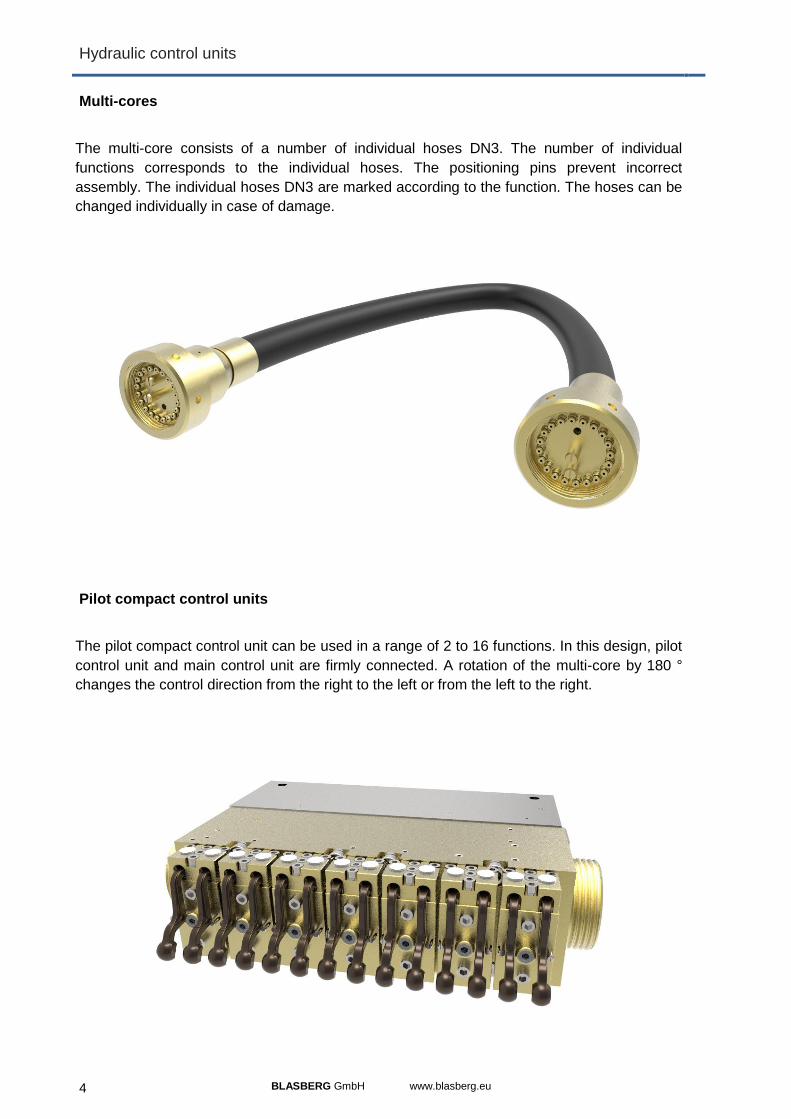
Multi-cores
The multi-core consists of a number of individual hoses DN3. The number of individual
functions corresponds to the individual hoses. The positioning pins prevent incorrect
assembly. The individual hoses DN3 are marked according to the function. The hoses can be
changed individually in case of damage.
Pilot compact control units
The pilot compact control unit can be used in a range of 2 to 16 functions. In this design, pilot
control unit and main control unit are firmly connected. A rotation of the multi-core by 180 °
changes the control direction from the right to the left or from the left to the right.

BLASBERG GmbH www.blasberg.eu 5
Hydraulic control units
Pilot control units
The pilot valves are mounted on the pilot control unit. Main and secondary functions can be
operated. All control units are designed and manufactured according to customer
requirements. The pilot valves operate according to the deadman principle. When the lever is
released, the cylinder stops moving. The pilot control unit is connected to the main control
block in the neighboring shield via the multi-core.
Pilot control unit with 20 functions
Pilot control unit with 10 functions

6 BLASBERG GmbH www.blasberg.eu
Solenoid valves
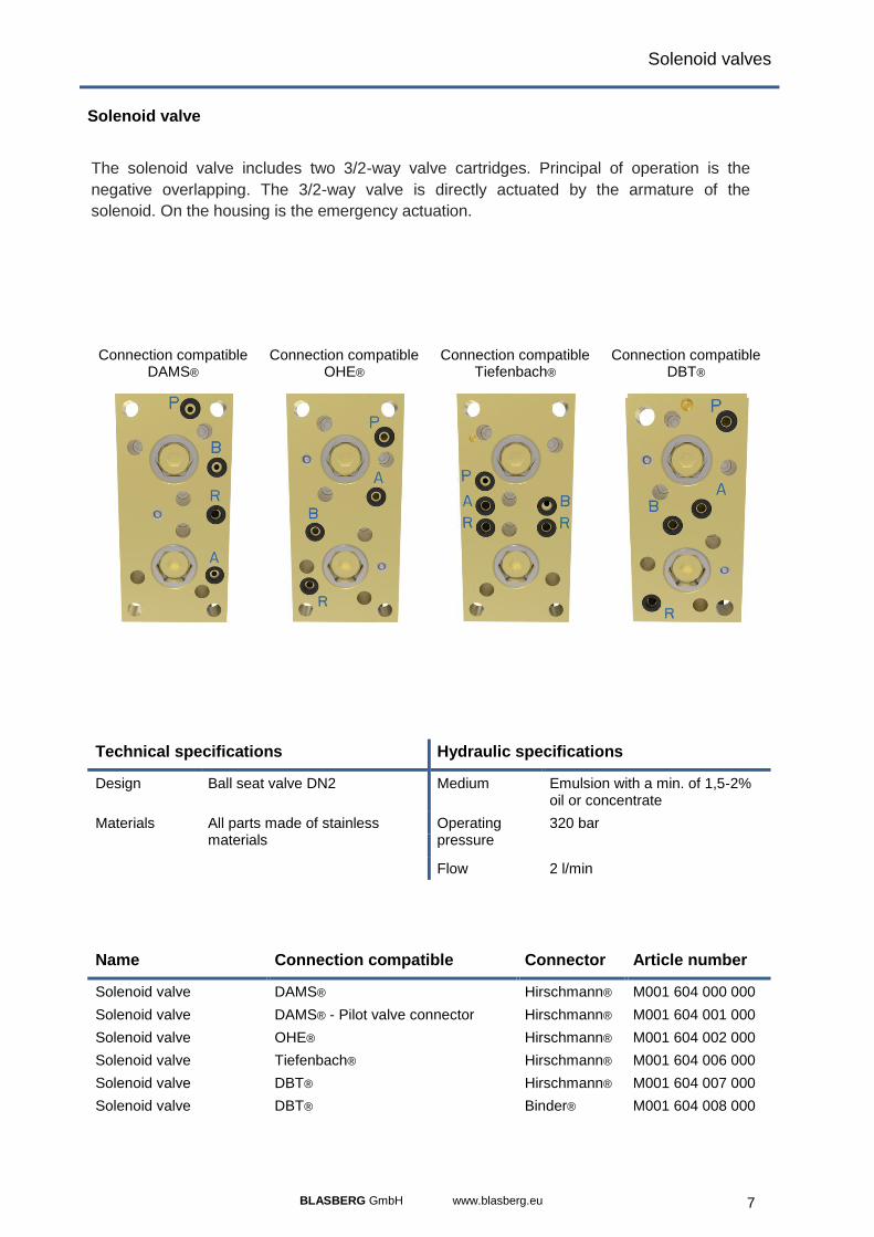
Solenoid valve
The solenoid valve includes two 3/2-way valve cartridges. Principal of operation is the
negative overlapping. The 3/2-way valve is directly actuated by the armature of the
solenoid. On the housing is the emergency actuation.
Solenoid valve Circuit diagram
Technical specifications Hydraulic specifications
Design Ball seat valve DN2 Medium Emulsion with a min. of 1,5-2% oil or concentrate
Materials All parts made of stainless materials
Operating pressure
320 bar
Flow 2 l/min
Name Connection compatible Connector Article number
Solenoid valve DAMS® Hirschmann® M001 604 000 000
Solenoid valve DAMS® - Pilot valve connector Hirschmann® M001 604 001 000
Solenoid valve OHE® Hirschmann® M001 604 002 000
Solenoid valve Tiefenbach® Hirschmann® M001 604 006 000
Solenoid valve DBT® Hirschmann® M001 604 007 000
Solenoid valve DBT® Binder® M001 604 008 000
BLASBERG GmbH www.blasberg.eu 7
Solenoid valves
Solenoid valve
The solenoid valve includes two 3/2-way valve cartridges. Principal of operation is the
negative overlapping. The 3/2-way valve is directly actuated by the armature of the
solenoid. On the housing is the emergency actuation.
Connection compatible DAMS®
Connection compatible OHE®
Connection compatible Tiefenbach®
Connection compatible DBT®
Technical specifications Hydraulic specifications
Design Ball seat valve DN2 Medium Emulsion with a min. of 1,5-2% oil or concentrate
Materials All parts made of stainless materials
Operating pressure
320 bar
Flow 2 l/min
Name Connection compatible Connector Article number
Solenoid valve DAMS® Hirschmann® M001 604 000 000
Solenoid valve DAMS® - Pilot valve connector Hirschmann® M001 604 001 000
Solenoid valve OHE® Hirschmann® M001 604 002 000
Solenoid valve Tiefenbach® Hirschmann® M001 604 006 000
Solenoid valve DBT® Hirschmann® M001 604 007 000
Solenoid valve DBT® Binder® M001 604 008 000

8 BLASBERG GmbH www.blasberg.eu
Spare parts for hydraulic controls
Check valves, pressure relief valves and plug-in filter
Pressure relief valves limit the pressure and protect the hydraulic system.
Check valves release flow in one direction. The flow is blocked in the opposite
direction.
Plug-in filters are used to clean the emulsion to protect the pilot valves. The
medium flows through the filter element from the outside to the inside. The filter is
used in pilot, compact and electrical controls.
M403 005 000 000 M403 005 010 000 M561 004 010 000
Technical specifications Hydraulic specifications
Materials All parts made of stainless materials
Medium Emulsion with a min. of 1,5-2% oil or concentrate
Name Connector Article number
Pressure relief valve M14x1 M403 005 000 000
check valve M14x1 M403 005 010 000
Plug-in filter DN10 M561 004 010 000

BLASBERG GmbH www.blasberg.eu 9
Over-center valves
Over-center valve
Over-center valves are pressure valves. When the consumer is triggered, the valve quickly
opens the outlet side. No pressure intensification can occur. Then it goes over damped into
the load-dependent throttle position. Starting jumps on consumers and associated pitching of
the components moved by them are thereby largely suppressed. The starting behavior is
achieved by way of threaded throttles with bypass check valves in the internal control
channels. The effectiveness of the threaded throttles can be changes within a certain range
and adapted to local requirements.
M127 933 G25 LHK Circuit diagram:
Technical specifications Hydraulic specifications
Design 33-G25-LHK Medium Emulsion with a min. of 1,5-2% oil or concentrate
Materials All parts made of stainless materials
Operating pressure
360 bar
Name V [l/min] Connector Article number
Over-center valve 60 G 1/2 M127 933 G25 LHK

10 BLASBERG GmbH www.blasberg.eu
Pressure relief valves
Pressure relief valves
Pressure relief valves limit the pressure in the working cylinder to a fixed
maximum value (set pressure). The piston of the valve remains closed
until the pressure on the piston surface exceeds the set spring force. The
outflow of the liquid takes place either into the open or into the return line.
The sealing principle of piston valve valves is the sealing of a piston by an
O-ring. The valve is also called the piston O-ring valve.
Circuit diagram:
M031 714 000 000 M031 584 000 000 M031 584 012 000 M031 414 040 000
Technical specifications Hydraulic specifications
Design Pressure relief valve piston-0-ring-valve
Medium Emulsion with a min. of 1,5-2% oil or concentrate
Materials All parts made of stainless materials
Operating pressure
120 – 550 bar
Name Pe [bar] Q [l/min] Connector Article number
Pressure relief valve M27x1,5 Max. 500 80 M27x1,5 M031 714 000 000
Pressure relief valve DN10 250 – 480 100 DN10 M031 584 000 000
Pressure relief valve DN12 250 – 480 100 DN12 M031 584 012 000
Pressure relief valve DN10 250 – 450 300 DN10 M031 414 040 000

BLASBERG GmbH www.blasberg.eu 11
Pressure relief valves
Pressure relief valves
Pressure relief valves limit the pressure in the working cylinder to a fixed
maximum value (set pressure). The piston of the valve remains closed
until the pressure on the piston surface exceeds the set spring force. The
outflow of the liquid takes place either into the open or into the return line.
The sealing principle of piston valve valves is the sealing of a piston by an
O-ring. The valve is also called the piston O-ring valve.
Circuit diagram:
M031 414 040 012 M031 184 010 000 M031 184 012 000 M031 184 020 000
Technical specifications Hydraulic specifications
Design Pressure relief valve piston-0-ring-valve
Medium Emulsion with a min. of 1,5-2% oil or concentrate
Materials All parts made of stainless materials
Operating pressure
120 – 550 bar
Name Pe [bar] Q [l/min] Connection Article number
Pressure relief valve DN12 250 – 450 300 DN12 M031 414 040 012
Pressure relief valve DN10 Max. 510 400 DN10 M031 184 010 000
Pressure relief valve DN12 Max. 510 400 DN12 M031 184 012 000
Pressure relief valve DN20 Max. 510 400 DN20 M031 184 020 000

12 BLASBERG GmbH www.blasberg.eu
Pressure relief valve
Pressure relief valve
Pressure relief valves limit the pressure in the working cylinder to a fixed
maximum value (set pressure). The piston of the valve remains closed
until the pressure on the piston surface exceeds the set spring force. The
outflow of the liquid takes place either into the open or into the return line.
The sealing principle of piston valve valves is the sealing of a piston by an
O-ring. The valve is also called the piston O-ring valve.
Circuit diagram:
M031 234 003 000 M031 234 001 000 M031 624 000 000
Technical specifications Hydraulic specifications
Design Pressure relief valve piston-0-ring-valve
Medium Emulsion with a min. of 1,5-2% oil or concentrate
Materials All parts made of stainless materials
Operating pressure
120 – 550 bar
Name Pe [bar] Q [l/min] Connection Article number
Pressure relief valve DN20/25 max. 510 1000 DN20/25 M031 234 003 000
Pressure relief valve M40 x 2 max. 510 1000 M40 x 2 M031 234 001 000
Pressure relief valve M40 x 2 max. 550 2600 M40 x 2 M031 624 000 000

BLASBERG GmbH www.blasberg.eu 13
Pressure relief valve
Spare parts for pressure relief valves
Pressure limiting valves limit the pressure in the working cylinder to a
fixed maximum value (set pressure PE of the DBV). The piston of the
valve remains closed until the pressure on the piston surface exceeds the
set spring force. The outflow of the liquid takes place either into the open
or into the return line. The pressure relief valves can be repaired using the
replacement piston with sealing kit.
Circuit diagram:
M031 504 010 003 M031 584 003 000 M031 414 040 003
M031 184 000 003 M031 234 000 003 M031 624 000 003
Name Pe [bar] Spare part for Article number
Piston with sealing kit max. 500 M031 714 000 000 M031 504 010 003
Piston with sealing kit 250 – 480 M031 584 000 000 M031 584 003 000
Piston with sealing kit 250 – 480 M031 584 000 012 M031 584 003 000
Piston with sealing kit 250 – 450 M031 414 040 000 M031 414 040 003
Piston with sealing kit 250 – 450 M031 414 040 012 M031 414 040 003
Piston with sealing kit max. 510 M031 184 010 000 M031 184 000 003
Piston with sealing kit max. 510 M031 184 012 000 M031 184 000 003
Piston with sealing kit max. 510 M031 184 020 000 M031 184 000 003
Piston with sealing kit max. 510 M031 234 003 000 M031 234 000 003
Piston with sealing kit max. 510 M031 234 001 000 M031 234 000 003
Piston with sealing kit max. 550 M031 624 000 000 M031 624 000 003

14 BLASBERG GmbH www.blasberg.eu
Way valves
3/2-Way valve cartridges
The main control valve cartridge is a 3/2-way valve with the nominal size
DN12 or DN20 with the connections DN10, DN12 or DN20. The valve
cartridge operates according to the cone-seat principle. The valve
cartridge allows large flow quantities with low pressure loss. In the flow
direction the cartridge is installed and reaches the maximum flow in this
installation. The piston of the valve cartridge is made of stainless steel
and is protected against wear. The valve cartridge is used in combination
with a pilot valve in direct pilot controls and electric controls.
Circuit diagram:
M005 004 010 000 M005 004 012 000 M005 004 020 000 M005 004 020 020
Technical specifications Hydraulic specifications
Design 3/2-way cone seat valve Medium Emulsion with a min. of 1,5-2% oil or concentrate
Materials All parts made of stainless materials
Operating pressure
350 bar
Name Connector Q [l/min] Article number
3/2 Way valve cartridge DN10 DN10 400 M005 004 010 000
3/2 Way valve cartridge DN12 DN12 600 M005 004 012 000
3/2 Way valve cartridge DN20 DN20 600 M005 004 020 000
3/2 Way valve cartridge DN20 DN20 1000 M005 004 020 020

BLASBERG GmbH www.blasberg.eu 15
Way valves
3/2-Way valve cartridges
The main control valve cartridge is a 3/2-way valve with the nominal size
DN12 or DN20 with the connections DN10, DN12 or DN20. The valve
cartridge operates according to the cone-seat principle. The valve
cartridge allows large flow quantities with low pressure loss. In the flow
direction the cartridge is installed and reaches the maximum flow in this
installation. The piston of the valve cartridge is made of stainless steel
and is protected against wear. The valve cartridge is used in combination
with a pilot valve in direct pilot controls and electric controls.
Circuit diagram:
M006 004 010 000 M006 004 012 000 M005 004 020 040 M006 004 020 000
Technical specifications Hydraulic specifications
Design 3/2-way cone seat valve Medium Emulsion with a min. of 1,5-2% oil or concentrate
Materials All parts made of stainless materials
Operating pressure
350 bar
Name Connector Q [l/min] Article number
3/2 Way valve cartridge DN10 DN10 400 M006 004 010 000
3/2 Way valve cartridge DN12 DN12 600 M006 004 012 000
3/2 Way valve cartridge DN20 DN20 1000 M005 004 020 040
3/2 Way valve cartridge DN20 DN20 1000 M006 004 020 000

16 BLASBERG GmbH www.blasberg.eu
Way valves
3/2-Wegeventilpatrone
The main control valve cartridge is a 3/2-way valve with the connections
DN12 or DN20. The valve cartridge operates according to the cone-seat
principle. The valve cartridge allows large flow quantities with low
pressure loss. In the flow direction the cartridge is installed and reaches
the maximum flow in this installation. The piston of the valve cartridge is
made of stainless steel and is protected against wear. The valve cartridge
is used in combination with a pilot valve in direct pilot controls and electric
controls.
Circuit diagram:
M012 003 024 000 M012 003 024 100 M012 003 024 110 M012 003 025 130
Technical specifications Hydraulic specifications
Design 3/2-way cone seat valve Medium Emulsion with a min. of 1,5-2% oil or concentrate
Materials All parts made of stainless materials
Operating pressure
350 bar
Name Connector Article number
3/2 Way valve cartridge DN12 long version DN12 M012 003 024 000
3/2 Way valve cartridge DN12 long version DN12 M012 003 024 100
3/2 Way valve cartridge DN12 short version DN12 M012 003 024 110
3/2 Way valve cartridge DN12 short with throttle DN12 M012 003 025 130

BLASBERG GmbH www.blasberg.eu 17
Way valves
3/2-Wegeventilpatrone
The main control valve cartridge is a 3/2-way valve with the connections
DN12 or DN20. The valve cartridge operates according to the cone-seat
principle. The valve cartridge allows large flow quantities with low
pressure loss. In the flow direction the cartridge is installed and reaches
the maximum flow in this installation. The piston of the valve cartridge is
made of stainless steel and is protected against wear. The valve cartridge
is used in combination with a pilot valve in direct pilot controls and electric
controls.
Circuit diagram:
M012 003 024 190 M012 003 026 130
Technical specifications Hydraulic specifications
Design 3/2-way cone seat valve Medium Emulsion with a min. of 1,5-2% oil or concentrate
Materials All parts made of stainless materials
Operating pressure
350 bar
Name Connector Article number
3/2 Way valve cartridge DN20 DN20 M012 003 024 190
3/2 Way valve cartridge DN20 with throttle DN20 M012 003 026 130

18 BLASBERG GmbH www.blasberg.eu
Way valves
3/2 Way valve cartridge series M004 004
The main control valve cartridge is a 3/2-way valve with nominal width
DN10. The valve cartridge operates according to the cone-seat principle.
The cartridge allows high flow rates with low pressure loss. In the flow
direction the cartridge is installed and reaches the maximum flow in this
installation. The piston of the valve cartridge is made of stainless steel
and is protected against wear. The valve cartridge is used in combination
with a pilot valve in direct pilot controls and electric controls.
Circuit diagram:
M004 004 000 000
M004 004 001 000
Technical specifications Hydraulic specifications
Design 3/2-way cone seat valve Medium Emulsion with a min. of 1,5-2% oil or concentrate
Materials All parts made of stainless materials
Operating pressure
320 bar
Name Nominal width Q [l/min] Article number
3/2 Way valve cartridge DN10 DN10 400 M004 004 000 000
3/2 Way valve cartridge DN10 DN10 400 M004 004 001 000

BLASBERG GmbH www.blasberg.eu 19
Way valves
Piston valve for HV4 pilot valve
The piston valve is a spare part for the HV4 control of OHE TYPE 64.103.01. The valve is a
4-3 way valve. The chambers are vacuum soldered. The piston is made of stainless steel
and hardened.
M112 764 103 901
Technical specifications Hydraulic specifications
Materials All parts made of stainless materials
Medium Emulsion with a min. of 1,5-2% oil or concentrate
Name Article number
Piston valve for HV4 pilot valve M112 764 103 901

20 BLASBERG GmbH www.blasberg.eu
Way valves
Pilot valves (DAMS® Connection compatible)
The pilot control valve is a double 3/2-way valve. The pilot control valves operate according to
the deadman principle, which means that after the lever has been released, the cylinder stops
moving. The valve operates with a negative switching overlap and is pressure-free in the non-
actuated state. During the switching process, the return is first closed; the pressure is
released and connected to the return. This is the reason why the valve is very soft. Locking
levers are mounted for functions that require permanent pressure. The connection of the pilot
control valves is compatible with Dams®.
M180 194 000 000 M180 294 000 000 M180 394 000 000 M180 494 000 000
Technical specifications Hydraulic specifications
Design Ball seat valve DN3 Medium Emulsion with a min. of 1,5-2% oil or concentrate
Materials All parts made of stainless materials
Operating pressure
320 bar
Dimension 88 x 40 x 30 mm Flow 20 l/min
Name Options Connection Article number
Pilot valve both normally closed DAMS® M180 194 000 000
Pilot valve right normally closed, left locked DAMS® M180 294 000 000
Pilot valve right locked, left normally closed DAMS® M180 394 000 000
Pilot valve both locked DAMS® M180 494 000 000

BLASBERG GmbH www.blasberg.eu 21
Way valves
Pilot valves (DAMS® Connection compatible and Centering hole)
The pilot control valve is a double 3/2-way valve. The pilot control valves operate according to
the deadman principle, which means that after the lever has been released, the cylinder stops
moving. The valve operates with a negative switching overlap and is pressure-free in the non-
actuated state. During the switching process, the return is first closed; the pressure is
released and connected to the return. This is the reason why the valve is very soft. Locking
levers are mounted for functions that require permanent pressure. The connection of the pilot
control valves is compatible with Dams®.
M180 184 000 000 M180 284 000 000 M180 384 000 000 M180 484 000 000
Technical specifications Hydraulic specifications
Design Ball seat valve DN3 Medium Emulsion with a min. of 1,5-2% oil or concentrate
Materials All parts made of stainless materials
Operating pressure
320 bar
Dimension 88 x 40 x 30 mm Flow 20 l/min
Name Options Connection Article number
Pilot valve both normally closed DAMS® M180 184 000 000
Pilot valve right normally closed, left locked DAMS® M180 284 000 000
Pilot valve right locked, left normally closed DAMS® M180 384 000 000
Pilot valve both locked DAMS® M180 484 000 000

22 BLASBERG GmbH www.blasberg.eu
Way valves
Pilot valves (Tiefenbach® Connection compatible)
The pilot control valve is a double 3/2-way valve. The pilot control valves operate according to
the deadman principle, which means that after the lever has been released, the cylinder stops
moving. The valve operates with a negative switching overlap and is pressure-free in the non-
actuated state. During the switching process, the return is first closed; the pressure is
released and connected to the return. This is the reason why the valve is very soft. Locking
levers are mounted for functions that require permanent pressure. The connection of the pilot
control valves is compatible with Tiefenbach®.
M180 194 085 000 M180 294 085 000 M180 394 085 000 M180 494 085 000
Technical specifications Hydraulic specifications
Design Ball seat valve DN3 Medium Emulsion with a min. of 1,5-2% oil or concentrate
Materials All parts made of stainless materials
Operating pressure
320 bar
Dimension 84 x 40 x 30 mm Flow 20 l/min
Name Options Connection Article number
Pilot valve both normally closed Tiefenbach® M180 194 085 000
Pilot valve right normally closed, left locked Tiefenbach® M180 294 085 000
Pilot valve right locked, left normally closed Tiefenbach® M180 394 085 000
Pilot valve both locked Tiefenbach® M180 494 085 000

BLASBERG GmbH www.blasberg.eu 23
Way valves
Replacement cartridge for pilot valves
The pilot control valve is a double 3/2-way valve. The pilot control valves operate according to
the deadman principle, which means that after the lever has been released, the cylinder stops
moving. The valve operates with a negative switching overlap and is pressure-free in the non-
actuated state. During the switching process, the return is first closed; the pressure is
released and connected to the return. This is the reason why the valve is very soft. Locking
levers are mounted for functions that require permanent pressure. The replacement cartridges
are available for the respective pilot valves.
M180 X94 085 000 M180 X84 000 000 M180 X94 000 000
Technical specifications Hydraulic specifications
Design Ball seat valve DN3 Medium Emulsion with a min. of 1,5-2% oil or concentrate
Materials All parts made of stainless materials
Operating pressure
320 bar
Name Connection Spare part for Article number
Valve cartridge for pilot valve Tiefenbach® M180 X94 085 000 M180 X94 085 100
Valve cartridge for pilot valve DAMS® M180 X84 000 000 M180 XX4 000 100
Valve cartridge for pilot valve DAMS® M180 194 000 000 M180 XX4 000 100

24 BLASBERG GmbH www.blasberg.eu
Single prop valves
Single prop valves and cartridge
The single prop valve is used to operate and Limit pressure in single props. The pressure
relief valve integrated in the single props secures the prop against overpressure. By inserting
the key into the bore of the single ram valve, the piston valve can be actuated mechanically.
The nozzle valve is opened by the rotation of the key and the prop withdraws.
.
M031 204 000 000 M031 504 000 000
M031 204 009 000 M031 504 010 050
Technical specifications Hydraulic specifications
Design Single prop valve Setting side: cone seat Pressure side: piston-0-ring valve Withdraw side: seat valve
Medium Emulsion with a min. of 1,5-2% oil or concentrate
Flow 60 l/min
Operating pressure
280 – 500 bar
Materials All parts made of stainless materials
Name Spare part for Article number
Single prop valve Klöckner M031 204 000 000
Single prop valve cartridge K with nozzle without outer sleeve (I u. II)
Klöckner M031 204 009 000
Single prop valve Salzgitter M031 504 000 000
Single prop valve cartridge S with nozzle without outer sleeve (I u. II)
Salzgitter M031 504 010 050

BLASBERG GmbH www.blasberg.eu 25
Single prop valves
Setting gun
The setting gun is used to set the single prop. The pistol is used to propel the prop in
combination with the single prop valve. The pressure relief valve integrated in the single prop
secures the prop against the set overpressure.
M990 024 000 000
Technical specifications Hydraulic specifications
Materials All parts made of stainless materials
Medium Emulsion with a min. of 1,5-2% oil or concentrate
Name Article number
Setting gun M990 024 000 000

26 BLASBERG GmbH www.blasberg.eu
Check valves
In-line check valves (female/male)
The in-line check valves of all nominal sizes and connection variants with
Female / Female or Female / Male allow the flow in one direction. The
flow is blocked in the opposite direction.
Circuit diagram:
M951 004 010 000 M951 004 012 000 M951 004 020 000
M951 004 025 000 M951 004 032 000
Technical specifications Hydraulic specifications
Design In-line check valve Cone seat valve
Medium Emulsion with a min. of 1,5-2% oil or concentrate
Materials All parts made of stainless materials
Operating pressure
Max. 530 bar
Name Connection Connection Pe [bar] Article number
In-line check valve DN10 Female/Male 530 M951 004 010 000
In-line check valve DN12 Female/Male 500 M951 004 012 000
In-line check valve DN20 Female/Male 450 M951 004 020 000
In-line check valve DN25 Female/Male 400 M951 004 025 000
In-line check valve DN32 Female/Male 300 M951 004 032 000

BLASBERG GmbH www.blasberg.eu 27
Check valves
In-line check valves (Female/Female)
The in-line check valves of all nominal sizes and connection variants with
Female / Female or Female / Male allow the flow in one direction. The
flow is blocked in the opposite direction.
Circuit diagram:
M951 004 010 050 M951 004 012 050 M951 004 020 050 M951 004 025 050
M951 004 032 050 M951 004 050 070 M951 004 050 075 M951 004 050 052
Technical specifications Hydraulic specifications
Design In-line check valve Cone seat valve
Medium Emulsion with a min. of 1,5-2% oil or concentrate
Materials All parts made of stainless materials
Operating pressure
Max. 530 bar
Name Connection Connection Pe [bar] Article number
In-line check valve DN10 Female/Female 530 M951 004 010 050
In-line check valve DN12 Female/Female 500 M951 004 012 050
In-line check valve DN20 Female/Female 450 M951 004 020 050
In-line check valve DN25 Female/Female 400 M951 004 025 050
In-line check valve DN32 Female/Female 300 M951 004 032 050
In-line check valve DN50 Female/Female 90 M951 004 050 070
In-line check valve DN50 Female/Female 350 M951 004 050 075
In-line check valve DN50 Female/Female 90 M951 004 050 052

28 BLASBERG GmbH www.blasberg.eu
Check valves
Prop check valves
The hydraulically unlockable prop pilot operated check valve consists of a 2-2-way valve
cartridge. The valve operates according to the cone-seat principle and is closed in the non-
activated position.
M850 854 020 062 M850 854 012 020
M854 104 012 210 M854 104 010 000
Technical specifications Hydraulic specifications
Design cone seat valve Medium Emulsion with a min. of 1,5-2% oil or concentrate
Materials All parts made of stainless materials
Nominal pressure
420 bar
Connection DN10
Connection DN 10; DN20; DN12
Name Article number
Unlockable prop check valve DN12 with tandem piston M850 854 020 062
Unlockable prop check valve M850 854 012 020
Valve cartridge with tandem piston M854 104 012 210
Valve cartridge M854 104 010 000

BLASBERG GmbH www.blasberg.eu 29
Check valves
Cylinder check valves
The hydraulically unlockable prop pilot operated check valve consists of a
2-2-way valve cartridge. The valve operates according to the cone-seat
principle and is closed in the non-activated position.
Circuit diagram:
M850 854 020 027 M854 104 012 210
M854 104 012 010 M854 104 012 115
Technical specifications Hydraulic specifications
Design cone seat valve Hydraulically unlockable
Medium Emulsion with a min. of 1,5-2% oil or concentrate
Materials All parts made of stainless materials
Operating pressure
500 bar
Name Spare part for Article number
Check valve DN20 with tandem piston, Hydraulically unlockable
M850 854 020 027
Valve cartridge with tandem piston M854 104 012 210
Screw-in socket with tandem piston M854 104 012 210 M854 104 012 010
Valve insert M854 104 012 210 M854 104 012 115
Valve insert M854 104 010 000 M854 104 012 115

30 BLASBERG GmbH www.blasberg.eu
Check valves
Twin check valves
The unlockable twin check valve DN10 (twin RSV) consists of two check valves cartridges.
The twin check valve is used to bring the working cylinder into a certain position by the
hydraulic pressure until the return flow of the medium is released by a control signal from the
other check valve. The unlockable twin check valve operates as follows: If the medium flows
through the one check valve, the other is relieved and the return flow can take place. (PT =
piston space, NT = annulus)
M811 854 000 062 M811 854 000 065
M854 204 010 100 M854 204 010 000
Technical specifications Hydraulic specifications
Design cone seat valve Medium Emulsion with a min. of 1,5-2% oil or concentrate
Materials All parts made of stainless materials
Nominal pressure
420 bar
Connection DN10
Name Article number
Unlockable twin check valve with tandem piston M811 854 000 062
Unlockable twin check valve M811 854 000 065
2/2- way valve cartridge with tandem piston M854 204 010 100
2/2- way valve cartridge M854 204 010 000

BLASBERG GmbH www.blasberg.eu 31
Shuttle valves
Spring and pressure loaded shuttle valves
Spring or pressure loaded shuttle valves are used in the shield support. These valves are
used for water spray valve while controlling a shield function or to pressurise both sides of a
cylinder. Shuttle valves are available either in ball seat or in cone seat design with parts in
DN10 or DN12. The spring gives the cone a defined position.
M530 204 010 000 M530 304 010 000
M530 204 012 000 M530 304 012 000
Technical specifications Hydraulic specifications
Design Spring loaded cone seat valve Pressure loaded cone seat valve
Medium Emulsion with a min. of 1,5-2% oil or concentrate
Materials All parts made of stainless materials
Operating pressure
350 bar
Name Connection Technology Article number
Pressure loaded shuttle valve DN10 DN10 Pressure M530 204 010 000
Pressure loaded shuttle valve DN12 DN12 Pressure M530 204 012 000
Spring loaded shuttle valve DN10 DN10 Spring M530 304 012 000
Spring loaded shuttle valve DN12 DN12 Spring M530 304 012 000

32 BLASBERG GmbH www.blasberg.eu
Filter units
In-line Filter (Connection Female/Male)
In-line filters of all nominal sizes protect the hydraulic system. High dirty
capacity and low pressure loss characterize these filters. The medium
flows through the filter element from the outside to the inside. The design
of the in-line filter is female/male. The replacement filter allows quick
repair of the in-line filters.
Circuit diagram:
M561 044 010 000 M561 044 012 000 M561 044 020 000
M561 044 012 010 M561 044 012 010 M561 044 020 010
Technical specifications Hydraulic specifications
Design Sieving filter Medium Emulsion with a min. of 1,5-2% oil or concentrate Filter density 25; 40 und 80 [μm]
Materials All parts made of stainless materials
Operating pressure
320 bar
Name Connection Connection Article number
In-line Filter DN10 Female/Male M561 044 010 000
In-line Filter DN12 Female/Male M561 044 012 000
In-line Filter DN20 Female/Male M561 044 020 000
Replacement filter DN10, DN12 M561 044 012 010
Replacement filter DN20 M561 044 020 010

BLASBERG GmbH www.blasberg.eu 33
Filter units
In-line Filter (Connection Female/female)
In-line filters of all nominal sizes protect the hydraulic system. High dirty
capacity and low pressure loss characterize these filters. The medium
flows through the filter element from the outside to the inside. The design
of the in-line filter is female/female. The replacement filter allows quick
repair of the in-line filters.
Circuit diagram:
M561 044 010 050 M561 044 012 050 M561 044 020 050
M561 044 012 010 M561 044 012 010 M561 044 020 010
Technical specifications Hydraulic specifications
Design Sieving filter Medium Emulsion with a min. of 1,5-2% oil or concentrate Filter density 25; 40 und 80 [μm]
Materials All parts made of stainless materials
Operating pressure
320 bar
Name Connection Connection Article number
In-line Filter DN10 Female/Female M561 044 010 050
In-line Filter DN12 Female/Female M561 044 010 050
In-line Filter DN20 Female/Female M561 044 010 050
Replacement filter DN10, DN12 M561 044 012 010
Replacement filter DN20 M561 044 020 010

34 BLASBERG GmbH www.blasberg.eu
Water spray valves
Water spray valves and cartridge
Water spray valves guarantee complete wetting of the working area in
order to protect miners from dust hazards. The water spray valve contains
a 2/2-way valve cartridge. Depending on the design, the valve can be
controlled from one or two directions.
Circuit diagram:
M400 534 000 000
M400 534 100 000
Technical specifications Hydraulic specifications
Design 2/2-way cone seat valve Medium Emulsion with a min. of 1,5-2% oil or concentrate
Materials All parts made of stainless materials
Nominal pressure
350 bar
Connection DN10
Name Article number
Water spray valve DN10 M400 534 000 000
Water spray valve cartridge M400 534 100 000
Changes and errors excepted. Similar pictures.
OHE® is a registered trademark of OHE GmbH. Germany
DAMS® is a registered trademark of DAMS GmbH, Germany
Tiefenbach® is a registered trademark of Tiefenbach GmbH, Germany
DBT® is a registered trademark of DBT GmbH, Germany
Hirschmann® is a registered trademark of Belden Electronics GmbH, Germany
Binder® is a registered trademark of Franz Binder GmbH & Co. Elektrische Bauelemente KG, Germany

Hydraulic controls
Pilot valves
Way valves
Single prop valves
Check valve
Shuttle valves
Filter
Water spray valves
BLASBERG GmbH Ringstraße 10a
42553 Velbert
Germany
Tel: +49 /(0)2053 / 49 342 - 0
Fax: +49 /(0)2053 / 49 342 – 22
www.blasberg.eu

2 BLASBERG GmbH www.blasberg.eu
BLASBERG GmbH
Ringstraße 10a
42553 Velbert
Germany
Tel: +49 /(0)2053 / 49 342 - 0
Fax: +49 /(0)2053 / 49 342 – 22
www.blasberg.eu