chapter 10 helical gears ( 斜齿圆柱齿轮). 10 - 2 force on helical gear teeth left hand...
TRANSCRIPT

Chapter 10 Helical gears (斜齿圆柱齿轮)
10- 2 Force on helical gear teeth
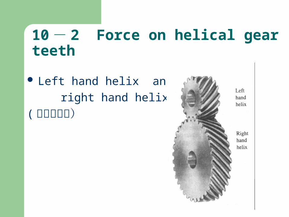
Left hand helix and
right hand helix
(左旋和右旋)

Helical gear geometry and forces

Force analysis of gear system
A gear train is composed of four helical gears with the shaft axes in a single plane. The gears have a 20 normal pressure angle and a 15helix angle and a normal module of mn=2mm .Gear 1is cut right-handed and has 16 teeth. The
gears on shaft b have 56 and 27 teeth respectively.. Gear 4 has 60 teeth. The driver rotates at 970 rpm and transmits 5kW. a) Calculate the center distance between shafts a,b and b,c. b) Calculate the pitch diameter of each gear. C)indicate the Wt 、Wr and Wx on each gear of shaft b.

The figure shows a gear train composed of a pair of straight bevel gears and a pair of helical gears. Shaft a is the input shaft of the train and delivers 17kW at a speed of 720 rpm. The bevel gears have a module of 5mm and a face with of gear is 50mm. The helical gears have a normal module of 6mm.
a)If the thrust forces on shaft b counteract , Indicate the hand of the helical
gears. b) . Indicate the Wt 、Wr and Wx on each gear of shaft b.

Example 10-1 A helical gear has a normal diametral pitch of
8, a normal pressure angle of 20º 32 teeth, a face width of 3.00 in, and a helix angle of 15º. Compute the diametral pitch, the transverse pressure angle, and the pitch diameter. If the gear is rotating at 650 rpm while transmitting 7.50 hp, compute the pitch line speed, the tangential force, the axial force, and the radial force.

10-3 stresses in helical gear teethThe bending stress:
where Ko = overload factor for bending strength Ks = size factor for bending strength Km = load distribution factor for bending strength KB = rim thickness factor Kv= dynamic factor for bending strengthSee bottom of page 399

10-4 pitting resistance for helical gear teeth
The contact stress
Where Cp= elastically coefficient (table 9-10)
I=geometry factor (table 10-1 10-2)
IFD
KKKKWCpSc
P
VmSOt

10-5 design of helical gears
A pair of helical gears for a milling machine drive is to transmit 65 hp with a pinion speed of
3 450 rpm and a gear speed of 1 100 rpm. The power is from an electric motor. Design the gears.