chapter7-drone-real-time particle systems on the gpu
TRANSCRIPT
Chapter 7: Real-Time Particle Systems on the GPU in Dynamic Environments
80
Chapter 7
Real-Time Particle Systems on the GPU in Dynamic
Environments
Shannon Drone13 Microsoft Corporation
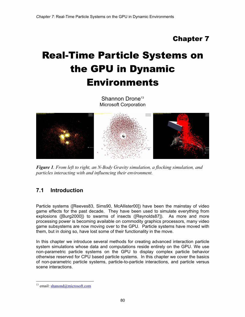
Figure 1. From left to right, an N-Body Gravity simulation, a flocking simulation, and particles interacting with and influencing their environment. 7.1 Introduction Particle systems ([Reeves83, Sims90, McAllister00]) have been the mainstay of video game effects for the past decade. They have been used to simulate everything from explosions ([Burg2000]) to swarms of insects ([Reynolds87]). As more and more processing power is becoming available on commodity graphics processors, many video game subsystems are now moving over to the GPU. Particle systems have moved with them, but in doing so, have lost some of their functionality in the move. In this chapter we introduce several methods for creating advanced interaction particle system simulations whose data and computations reside entirely on the GPU. We use non-parametric particle systems on the GPU to display complex particle behavior otherwise reserved for CPU based particle systems. In this chapter we cover the basics of non-parametric particle systems, particle-to-particle interactions, and particle versus scene interactions.
13 email: [email protected]

Advanced Real-Time Rendering in 3D Graphics and Games Course – SIGGRAPH 2007
81
For the intents of this chapter, we base our approach on an assumption that the particle system data is not instrumental to gameplay and that the CPU does not need to results of particle system operations to perform any other game-related functions. However, it is a fairly straightforward extension of our approach to provide particle data back to the CPU by read-back. 7.2 Rendering System Requirements While many of the methods described here can be adapted to work on the majority of consumer video graphics hardware currently in the market, some techniques require the use of more advanced features that can only be found on Direct3D 10-level graphics devices (as described in [Blythe06]). For the following techniques we assume that the video hardware is a recent video card that supports at least a Direct3D 10 level of functionality. In our case we are specifically going to take advantage of such features of this generation of hardware as additive alpha blending; instancing support; the ability render directly to volume textures; the ability to sample textures or data buffers from any stage of the pipeline; support for pixel, vertex, and geometry shaders; the ability to save transformed geometry back into GPU memory; texture array support; and automatic generation of mip-maps. 7.3 Non-Parametric Particle Systems Parametric or stateless particle systems are easy to handle in programmable graphics pipelines. Because each particle position is described parametrically the position of the particle at any time can be determined by plugging that time into an equation of motion. This approach has two main benefits. The first is that it requires no extra storage for intermediate particle state. The second is that it is an exact analytical solution to the path of motion for the particle. No integration of the equations of motion is required to find the position of the particle. Unfortunately, there are drawbacks to using parametric systems. The main one is that once set, the motion of a particle cannot change. This limits the ability of a parametric particle system to react to its environment in real-time. In addition, it limits the system to paths of motion with known analytical solutions (as described in [Lutz04]). For our work, we use non-parametric particle systems similar to [Lutz04]. These work on the premise that the equations of acceleration are integrated over the course of the simulation to compute instantaneous velocity. The velocity equation is integrated over the course of the simulation to compute instantaneous position. This approach is less accurate than a purely analytical parametric solution, but maintains a level of flexibility and interaction far beyond a parametric system.
Chapter 7: Real-Time Particle Systems on the GPU in Dynamic Environments
82
7.3.1 Storage Requirement In order to integrate the equations of acceleration and velocity, we must store the immediate values for the previous frame’s instantaneous velocity and position. These will be known as the particle’s state. For the remaining techniques, we can store particle state using either of two storage objects readily available on current graphics hardware. The first option is to store state in a vertex buffer. In this approach, each vertex represents the state of one particle in its entirety. It must contain at a minimum, the instantaneous position and velocity of the particle at the current time value. The particles are stored linearly in the vertex buffer object. The second option is to store the particle state in series of floating point textures. Whereas [Lutz04] used several individual textures to store the data, we split the data between multiple slices of a single texture array. A texture array is a single object that acts as a container for an array of traditional textures. The first array slice stores instantaneous position and the second instantaneous velocity. Additional array slices may be used to store additional data. This data could be stored in one-dimensional textures, but size limitations on one-dimensional textures for current API and hardware versions would limit us to 8192 particles in the best case. Therefore, we store particle state in two-dimensional textures where the height and width of the texture are the next largest integral square of the number of particles.
7.3.2 Integrating the Equations of Motion Because the particle state is integrated using a series of instantaneous accelerations and velocities, the accuracy of the solution depends entirely on the length of time between the calculation of the previous values and the current values as well as the integration technique used. Simple Euler integration will work in most cases where the behavior is simple or where the time between calculations is sufficiently small. However, a more advanced integration such as a Runge-Kutta based integration scheme maybe be used where further accuracy is required. Note that using a more advanced integration solution may require storage of several previous particle states. For the techniques expressed here, we use Euler integration.
7.3.3 Saving Particle States The current methodology of integrating particle motion requires a read-modify-write operation on the particle state data. The Euler integration scheme for velocity requires that the current velocity be known and added to the instantaneous acceleration scaled by the current time step. Unfortunately, read-modify-write operations are illegal in the programmable parts of the current graphics pipeline (they are allowed in the blend stages which are currently not programmable). The solution is use a “ping-pong” technique to essentially double buffer the data. In the particle update phase, the buffer

Advanced Real-Time Rendering in 3D Graphics and Games Course – SIGGRAPH 2007
83
or texture being sampled contains the instantaneous particle state for the previous frame. The particle update phase stores the new instantaneous particle state in other buffer or texture. The buffers or textures are swapped for the next frame so that the particle update phase is always reading from the previous frame’s data.
7.3.4 Changing Behaviors Because our particles are no longer affixed to a predestined path of motion, changing behaviors of individual particles is as easy as changing their individual velocities or positions. While these will result in an immediate change of motion for the particle, a change in position will cause a break in the C1 continuity (or the position curve), while a change in velocity will cause a break in the C2 continuity (i..e the derivative of the position curve). In the following techniques, we will only change acceleration, and therefore only break C3 of the position curve. This results in a much smoother visual appearance of particle motion. 7.4 Particles That React to Other Particles
Figure 2. Flocking and gravity simulations
Chapter 7: Real-Time Particle Systems on the GPU in Dynamic Environments
84
7.4.1 N-Body Problems Many particle systems require that every particle influence every other particle in the system. These are generally classified as N-Body problems. We outline a method of dealing with N-Body problems on the GPU.
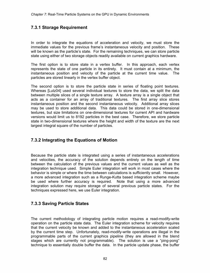
7.4.2 Force Splatting for N2 Particle Interactions The goal of force splatting is to project the force from one particle onto all other particles during a single operation. In this case, the operation is the rendering of a quad primitive. We create a texture that acts and an accumulation buffer for all forces applied to the particles. This buffer will be the target of the rasterization operations that will accumulate particle forces. Each texel in the force texture holds the accumulated forces acting upon a single particle. We also create a stack of N quad primitives, where N is the number of particles in the system. The dimensions of the quads are such that they will exactly cover the force buffer when rasterized. The four vertices of each quad in the stack contain a vertex element which identifies the exact particle represented by the quad. During rasterization, this interpolated vertex element is used to fetch properties of the particle from the particle texture or the particle buffer.
Figure 3. Force splatting by rendering multiple into a force texture with alpha blending During the rasterization of a single quad, the forces are calculated between the particle being rasterized to and the particle represented by the vertex element in the vertices of the quad. Forces are accumulated by rendering successive quad with additive alpha blending enabled. While less than elegant in terms of algorithmic complexity, the force splatting algorithm exploits the fast rasterization and alpha blending capabilities of modern graphics hardware without the need to continually recreate complex space partitioning structures on the GPU.

Advanced Real-Time Rendering in 3D Graphics and Games Course – SIGGRAPH 2007
85
7.4.3 Gravity Simulation
Figure 4. N-body gravity simulation using force splatting to accumulate forces between all N particles
7.4.3.1 Using Force Splatting for Gravity Interactions To compute the gravitational force of all particles to all other particles, we use the method of force splatting mentioned above to accumulate all of the forces imparted on each particle in the system. In the particle update phase, this force is divided by the particle’s mass to determine the instantaneous acceleration of the particle. The equations of motion are integrated, and the particle system is updated.

Chapter 7: Real-Time Particle Systems on the GPU in Dynamic Environments
86
7.4.4 Flocking Particles on the GPU
Figure 5. A boids implementation handled entirely on the GPU. Particles use force splatting for collision avoidance, and separation while using fast mip map generation for coherence and goal seeking. A single space-ship mesh is then instanced using particle position and orientation as a transform. Perhaps more relevant to game development is the idea of flocking particle systems. Oftentimes particle systems are used to create the illusion of flocks of birds or bugs swarming around a light or fallen comrade. Traditional flocking behaviors need to follow a few simple rules in order to look plausible. In this situation, the rules are collision avoidance, separation, cohesion, and alignment. See [Reynolds87, Reynolds99] for in-depth descriptions of flocking behaviors.
7.4.4.1 Force Splatting for Collision Avoidance and Separation The flocking simulation takes advantage of the previous N2 force splatting to avoid collisions between particles as well as to maintain a certain comfortable separation between all particles. Instead of computing the gravitational attraction between particles,
Advanced Real-Time Rendering in 3D Graphics and Games Course – SIGGRAPH 2007
87
we’re computing a repellant force for each particle based upon either how close the particles are to colliding or how much space is between particles.
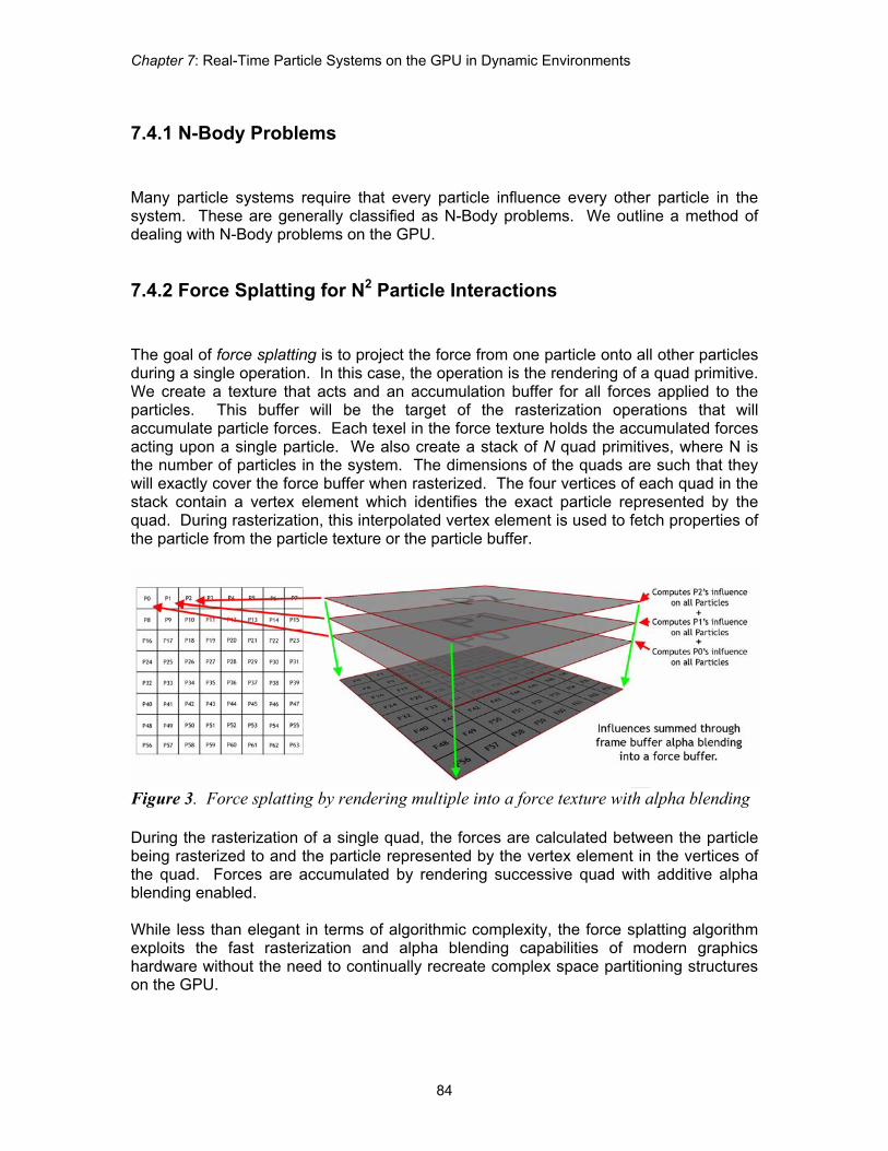
7.4.4.2 Fast Averaging for Cohesion and Alignment Behaviors such as cohesion and alignment rely on the knowledge of the average position and average velocity of the particles respectively. Fortunately, modern graphics hardware provides a fast way of averaging entire textures by being able to generate mip-maps on the fly. By sampling from the smallest mip-level during the particle update phase, we can create a force vector from the particle to the center of mass for cohesion or create a force vector that aligns our particle with the average velocity of all other particles. This force vector is added to the force vector sampled from the force accumulation texture.
Figure 6. Fast averaging of particle states by generating mip-maps
7.5 Particles Reacting to Their Environments In order for non-parametric particle systems to have a true advantage over parametric or scripted systems, they must react to their environments as well as to each other.
Chapter 7: Real-Time Particle Systems on the GPU in Dynamic Environments
88
7.5.1 Reacting to Spherical Objects
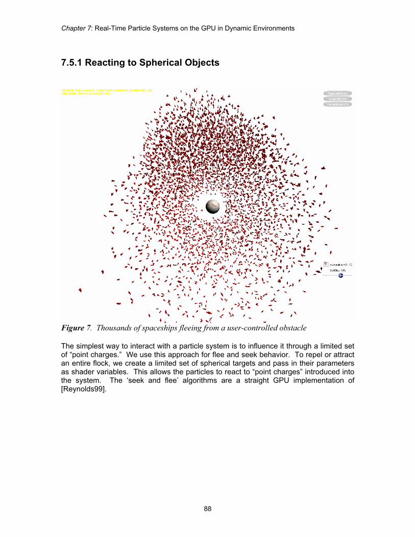
Figure 7. Thousands of spaceships fleeing from a user-controlled obstacle The simplest way to interact with a particle system is to influence it through a limited set of “point charges.” We use this approach for flee and seek behavior. To repel or attract an entire flock, we create a limited set of spherical targets and pass in their parameters as shader variables. This allows the particles to react to “point charges” introduced into the system. The ‘seek and flee’ algorithms are a straight GPU implementation of [Reynolds99].
Advanced Real-Time Rendering in 3D Graphics and Games Course – SIGGRAPH 2007
89
7.5.2 Reacting to Arbitrary Objects Using Render-to-Volume
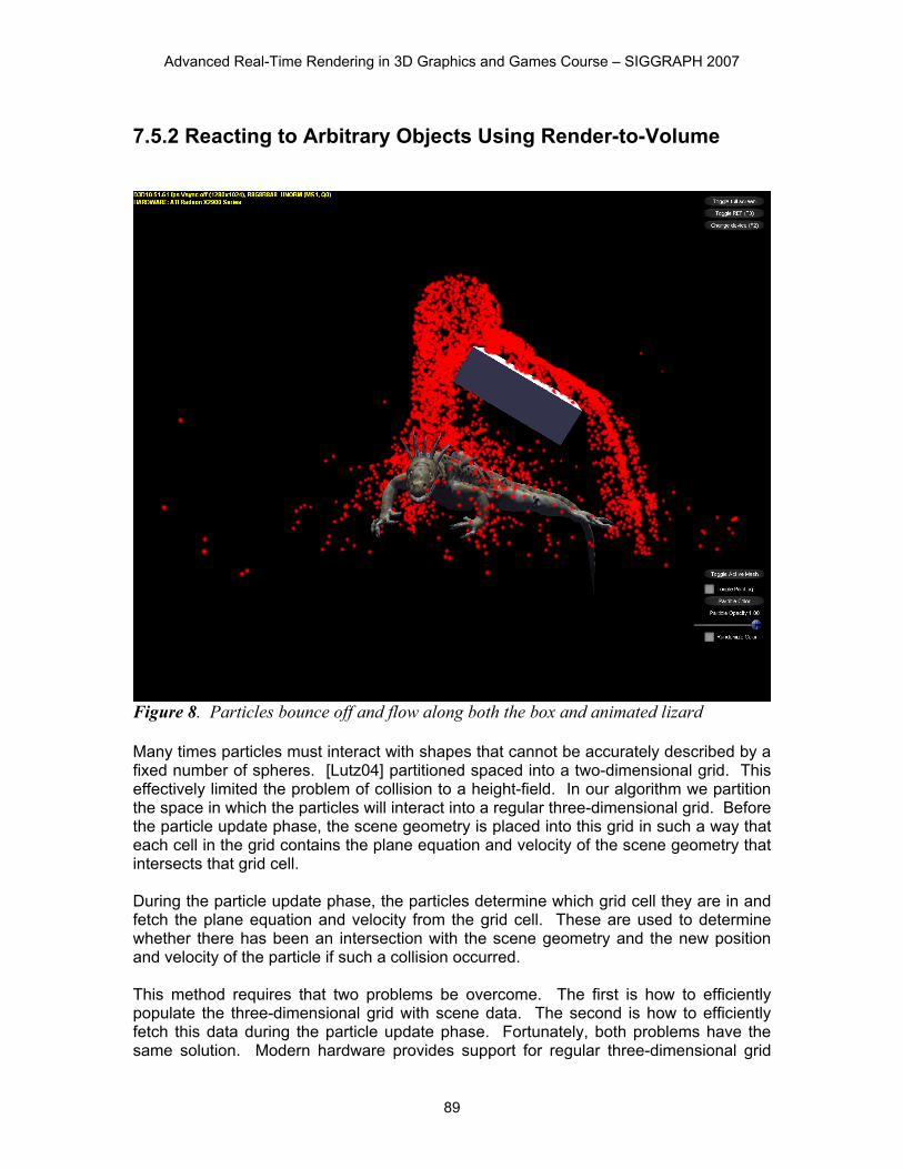
Figure 8. Particles bounce off and flow along both the box and animated lizard Many times particles must interact with shapes that cannot be accurately described by a fixed number of spheres. [Lutz04] partitioned spaced into a two-dimensional grid. This effectively limited the problem of collision to a height-field. In our algorithm we partition the space in which the particles will interact into a regular three-dimensional grid. Before the particle update phase, the scene geometry is placed into this grid in such a way that each cell in the grid contains the plane equation and velocity of the scene geometry that intersects that grid cell. During the particle update phase, the particles determine which grid cell they are in and fetch the plane equation and velocity from the grid cell. These are used to determine whether there has been an intersection with the scene geometry and the new position and velocity of the particle if such a collision occurred. This method requires that two problems be overcome. The first is how to efficiently populate the three-dimensional grid with scene data. The second is how to efficiently fetch this data during the particle update phase. Fortunately, both problems have the same solution. Modern hardware provides support for regular three-dimensional grid

Chapter 7: Real-Time Particle Systems on the GPU in Dynamic Environments
90
structures in the form of volume textures. Additionally, volume textures can be rendered into or sampled using the graphics hardware.
7.5.2.1 Populating the Volume Texture The volume texture must be populated with the scene geometry once slice at a time. Normally this would require a separate invocation of the rendering pipeline for each slice of the volume and then again for each object to be rendered. However, the latest advances in graphics hardware provide the ability to bind all slices of the volume to the pipeline at once and selectively output geometry to each slice, therefore reducing the process to one invocation of the rendering pipeline for each object. This latest advancement in graphics hardware comes in the form of a new addition to the rendering pipeline called the geometry shader. In addition to being able to specify output slices into a volume render target, the geometry shader can also perform operations on whole primitives. The process works as follows: the scene geometry is drawn with hardware instancing turned on. We draw S instances of the scene geometry where S is the number of slices of the volume texture. In the shader, each triangle primitive is sent to a different slice of the volume depending on the instance ID of the geometry.
Figure 9. Rendering an object into a volume using instancing to send it to all slices

Advanced Real-Time Rendering in 3D Graphics and Games Course – SIGGRAPH 2007
91
Using the aforementioned geometry shader, the plane equation for the primitive is computed and passed along to the pixel shader along with the velocities of each of the vertices. In order to ensure only geometry that passes through a particular slice ends up being rasterized to that slice, user specified clip planes are provided to clip any geometry that falls outside of its specified slice. The pixel shader then outputs the plane equation and interpolated velocity into the volume texture.
Figure 10. The plane equation and velocity are rendered into each voxel of the volume
7.5.2.2 Sampling the Volume Texture
In the particle update phase, the particle volume texel that encompasses the particle is sampled for its plane equation and velocity. The particle is then checked for collisions against the plane equation. If a collision occurs, the particle is deflected according to its own velocity, the plane equation, and the plane velocity.
Chapter 7: Real-Time Particle Systems on the GPU in Dynamic Environments
92
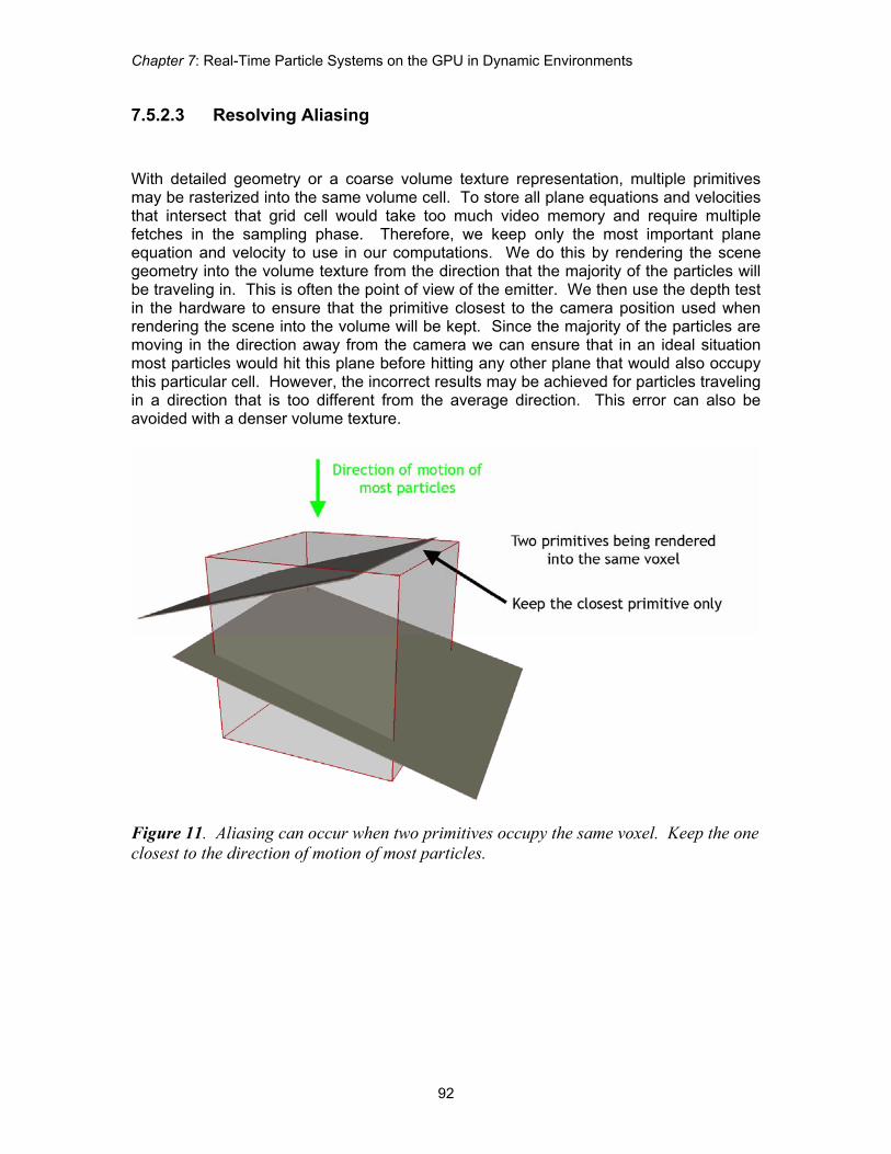
7.5.2.3 Resolving Aliasing With detailed geometry or a coarse volume texture representation, multiple primitives may be rasterized into the same volume cell. To store all plane equations and velocities that intersect that grid cell would take too much video memory and require multiple fetches in the sampling phase. Therefore, we keep only the most important plane equation and velocity to use in our computations. We do this by rendering the scene geometry into the volume texture from the direction that the majority of the particles will be traveling in. This is often the point of view of the emitter. We then use the depth test in the hardware to ensure that the primitive closest to the camera position used when rendering the scene into the volume will be kept. Since the majority of the particles are moving in the direction away from the camera we can ensure that in an ideal situation most particles would hit this plane before hitting any other plane that would also occupy this particular cell. However, the incorrect results may be achieved for particles traveling in a direction that is too different from the average direction. This error can also be avoided with a denser volume texture.
Figure 11. Aliasing can occur when two primitives occupy the same voxel. Keep the one closest to the direction of motion of most particles.

Advanced Real-Time Rendering in 3D Graphics and Games Course – SIGGRAPH 2007
93
Figure 12. One way to combat aliasing is to use a denser volume texture 7.6 Environments That React to Particles
Figure 13. The particles paint into the diffuse channel of the box and lizard when they intersect the objects.
Chapter 7: Real-Time Particle Systems on the GPU in Dynamic Environments
94
Finally, we show how particles can actually affect their environments. We use the particles to affect the appearance of the world geometry.
7.6.1 Painting with Particles Using a Gather Approach Finally, we show how the appearance of the scene geometry can change based upon it’s interaction with particles. In particular, the particles will apply paint to any part of the object that they encounter.
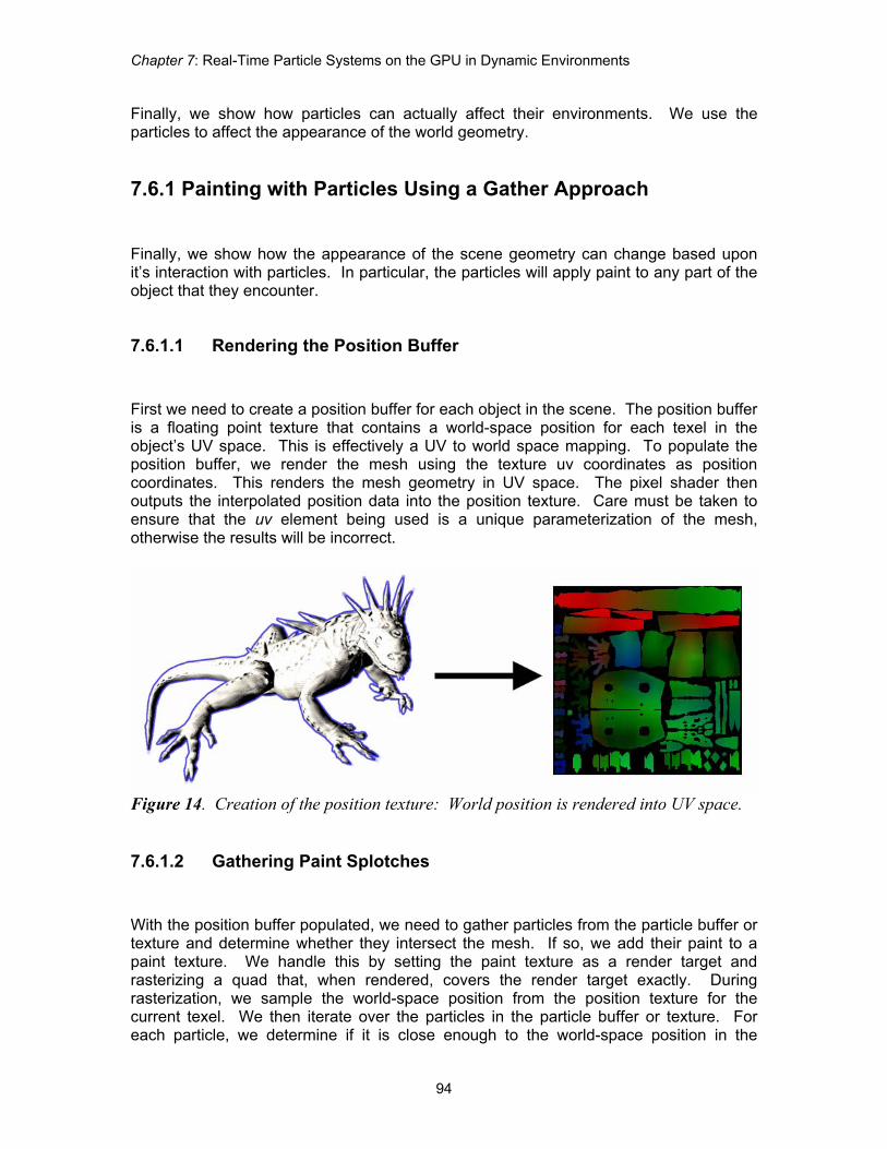
7.6.1.1 Rendering the Position Buffer First we need to create a position buffer for each object in the scene. The position buffer is a floating point texture that contains a world-space position for each texel in the object’s UV space. This is effectively a UV to world space mapping. To populate the position buffer, we render the mesh using the texture uv coordinates as position coordinates. This renders the mesh geometry in UV space. The pixel shader then outputs the interpolated position data into the position texture. Care must be taken to ensure that the uv element being used is a unique parameterization of the mesh, otherwise the results will be incorrect.
Figure 14. Creation of the position texture: World position is rendered into UV space.
7.6.1.2 Gathering Paint Splotches With the position buffer populated, we need to gather particles from the particle buffer or texture and determine whether they intersect the mesh. If so, we add their paint to a paint texture. We handle this by setting the paint texture as a render target and rasterizing a quad that, when rendered, covers the render target exactly. During rasterization, we sample the world-space position from the position texture for the current texel. We then iterate over the particles in the particle buffer or texture. For each particle, we determine if it is close enough to the world-space position in the

Advanced Real-Time Rendering in 3D Graphics and Games Course – SIGGRAPH 2007
95
position buffer to leave any paint. If so, we add the paint influence to the total paint output for this pixel shader invocation.
Figure 15. A pixel shader passes over the position texture. For each particle, it determines whether the current position intersects the particle. If it does, it outputs an appropriate amount of paint into the diffuse texture.
7.6.1.3 Amortizing the Gather over Time For systems containing thousands of particles, iterating over all particles during gather time may not provide the best frame rate. For hardware with a fixed instruction count it may not be possible to loop over all particles. We amortize the cost of gathering over several frames by determining a fixed amount of particles to gather. For example, for the first frame we gather the first G particles. For the next frame we gather the next G particles, and so on until we loop back around to the beginning of the particle buffer. This gives much better performance with little loss in the quality of the effect.
7.7 Acknowledgements We would like to thank Matt Dudley for the lizard art. 7.8 References [BLYTHE06] BLYTHE, D. 2006. The Direct3D 10 system. ACM Trans. Graph. 25, 3, pp. 724-
734. [BURG00] J. VAN dER BURG. 2000. Building an Advanced Particle System. Gamasutra,
June 2000.

Chapter 7: Real-Time Particle Systems on the GPU in Dynamic Environments
96
[LUTZ04] LUTZ, L. 2004. Bulding a Million Particle System. In proceedings of Game
Developers Conference, San Francisco, CA, March 2004. [MCALLISTER00] McAllister, D. K. 2000. The Design of an API for Particle Systems.
University of North Carolina Technical Report TR 00-007 [REEVES83] REEVES, W. T. 1983. Particle systems -- a technique for modeling a class of
fuzzy objects. ACM Transactions on Graphics, 2(2), pp. 91-108, Apr. 1983. [REYNOLDS87] REYNOLDS, C. 1987. Flocks, Herds and Schools: A Distributed Behavioural
Model. Computer Graphics, 21(4), pp.25-34. [REYNOLDS99] REYNOLDS, C. W. 1999. Steering Behaviors for Autonomous Characters, in
the proceedings of Game Developers Conference 1999 held in San Jose, California. Miller Freeman Game Group, San Francisco, California. pp. 763-782.
[SIMS90] SIMS, K. 1990. Particle Animation and Rendering Using Data Parallel
Computation. ACM Computer Graphics (SIGGRAPH '90), 24(4), pp. 405-413, August 1990.