city of laredo - environmental services departmentesd.ci.laredo.tx.us/esdweb/swgm1.pdf · the...
TRANSCRIPT

CITY OF LAREDO
STORM WATER MANAGEMENT
GUIDANCE MANUAL

TABLE OF CONTENTS
SECTION 1 DESIGN CRITERIA and SUPPLEMENTAL INFORMATION
1 . RAINFALL INTENSITY AND MAXIMUM DURATION DETERMINATION . . . . . . . . . . . 1 a . Rainfall Intensity (i) . . . . . . . . . . . . . . . . . . . . . . . . . . . . . . . . . . . . . . . . . . . . . . . 1 b . Maximum Expected Rainfall: . . . . . . . . . . . . . . . . . . . . . . . . . . . . . . . . . . . . . . . . 2
2 . RUNOFF COEFFICIENTS . . . . . . . . . . . . . . . . . . . . . . . . . . . . . . . . . . . . . . . . . . . . . . . 2 a . Recommended Rational Method "C" Values . . . . . . . . . . . . . . . . . . . . . . . . . . . . 2 b . Recommended SCS Method "CN" Values . . . . . . . . . . . . . . . . . . . . . . . . . . . . . 3
3 . ALLOWABLE MANNING'S "n" COEFFICIENTS . . . . . . . . . . . . . . . . . . . . . . . . . . . . . . . 4
. . . . . . . . . . . . . . . . . . . . . 4 . FREEBOARD AND SUPERELEVATION REQUIREMENTS 9 a . Freeboard . . . . . . . . . . . . . . . . . . . . . . . . . . . . . . . . . . . . . . . . . . . . . . . . . . . . . . . 9 b . Superelevation . . . . . . . . . . . . . . . . . . . . . . . . . . . . . . . . . . . . . . . . . . . . . . . . . . . 9
5 . STORM WATER RUNOFF CALCULATION METHODS . . . . . . . . . . . . . . . . . . . . . . . 10
6 . DESIGN GUIDELINES FOR WATER QUALITY CONTROL BASINS . . . . . . . . . . . . . 10 a . Water Quality Volume . . . . . . . . . . . . . . . . . . . . . . . . . . . . . . . . . . . . . . . . . . . . 10 b . Storm Water Quality Treatment Options . . . . . . . . . . . . . . . . . . . . . . . . . . . . . . 11
i . Off-Line detention . . . . . . . . . . . . . . . . . . . . . . . . . . . . . . . . . . . . . . . . . 11 II . On-Line detention . . . . . . . . . . . . . . . . . . . . . . . . . . . . . . . . . . . . . . . . . 11 iii . WetDetention . . . . . . . . . . . . . . . . . . . . . . . . . . . . . . . . . . . . . . . . . . . . 11
. . . . . . . . . . . . . . . . . . . . . . . . . . . . . . . . . . . . . . . . . . . . . . . . . . . . . . . . . 7 . EASEMENTS 12
8 . RETAINING WALL DESIGN . . . . . . . . . . . . . . . . . . . . . . . . . . . . . . . . . . . . . . . . . . . . . 12
SECTION 2 BEST MANAGEMENT PRACTICES
BMP 1 . Interceptor Swale BMP 2 . Diversion Dike BMP 3 . Pipe Slope Drain BMP 4 . Vegetation BMP 5 . Mulching BMP 6 . Erosion Control Mats BMP 7 . Silt Fence BMP 8 . Permanent Structural Controls BMP 9 . Hay Bale Dike BMP 10 . Triangular Sediment Filter Dike BMP 11 . Inlet Protection BMP 12 . Stone Outlet Sediment Trap

BMP 13 - Sediment Basin BMP 14 - Check Dams BMP 15 - Stabilized Construction Entry BMP 16 - Sandbag Berm BMP 17 - Lime Stabilization Control BMP BMP 18 - Solid Waste Management BMP 19 - Hazardous Waste Management BMP 20 - Concrete Waste Management BMP 21 - Infiltration BMP 22 - Retention Ponds BMP 23 - Extended Detention Basin BMP 24 - Porous Pavement BMP 25 - OilNVater Separators BMP 26 - Vehicle and Equipment Maintenance / Repair BMP 27 - Vehicle and Equipment Washing, Cleaning BMP 28 - Vehicle and Equipment Fueling BMP 29 - Spill Prevention and Control

SECTION 1
DESIGN CRITERIA and
SUPPLEMENTAL INFORMATION

RAINFALL INTENSITY AND MAXIMUM DURATION DETERMINATION
a. Rainfall Intensity (i)
Rainfall intensity (i) is the average rainfall rate in inches per hour, and is selected on the basis of design rainfall duration and design frequency of occurrence. The design duration is equal to the time of concentration for the drainage area under consideration. The design frequency of occurrence is a statistical variable which is established by design standards or chosen by the engineer as a design parameter.
The rainfall intensity used in the rational method is read from the intensity-duration- frequency curves based on the selected design frequency and design duration.
The following equation represents mathematically the City of Laredo intensity- duration-frequency curves:
where:
i = Average rainfall intensity, inches per hour t = Storm duration, minutes b,d & e = Coefficients for different storm frequencies
The values for b,d and e as published in TXDOT Hydraulics Manual, 1987, are:
City of Laredo Intensity-Duration-Frequency Curve Coefficients I
Laredo Storm Water Management Guidance Manual
I Area Y
I Webb I I
I County
-
2-Year 5-Year 1 10-Year 1 25-Year 5O-yearJ 100-Year All - - - - -- -* - -
I Frequenc~es
083 81 66 0.801 0812 90
e b e b e b e b e b e b
0.781 95 0781
-
103
--
d
077 110 9 6 -

b. Maximum Expected Rainfall:
I Duration (Hours) , 1 2 1 5 10 26 50 100
r - -- - - - -
MAXIMUM EXPECTED RAINFALL AMOUNTS (INCHES) PER DURATION
FOR RECURRENCE INTERVALS
RUNOFF COEFFICIENTS
a. Recommended Rational Method "C" Values
1 Rainfall
1 Average Runoff Coefficient for "C" in formula Q = CIA
Rainfall Recurrence Interval (Years) I
I 1 Parks & permanent open space (AG)
HYDROLOGIC SOIL GROUPS
Multi-Family (RSM, R-2, R-3, B-I)
- - - -
I Commercial ' (8-3, 8-4, M- 1, M-2)
-- - - -
Central Business District (8-2)
-
Sandy & Silty Classification) Aggregated Loams
Silts ,
Laredo Storm Water Management Guidance Manual
Clay Loam. Heavy Plastic Shallow Sandy Clays I
Loams 1
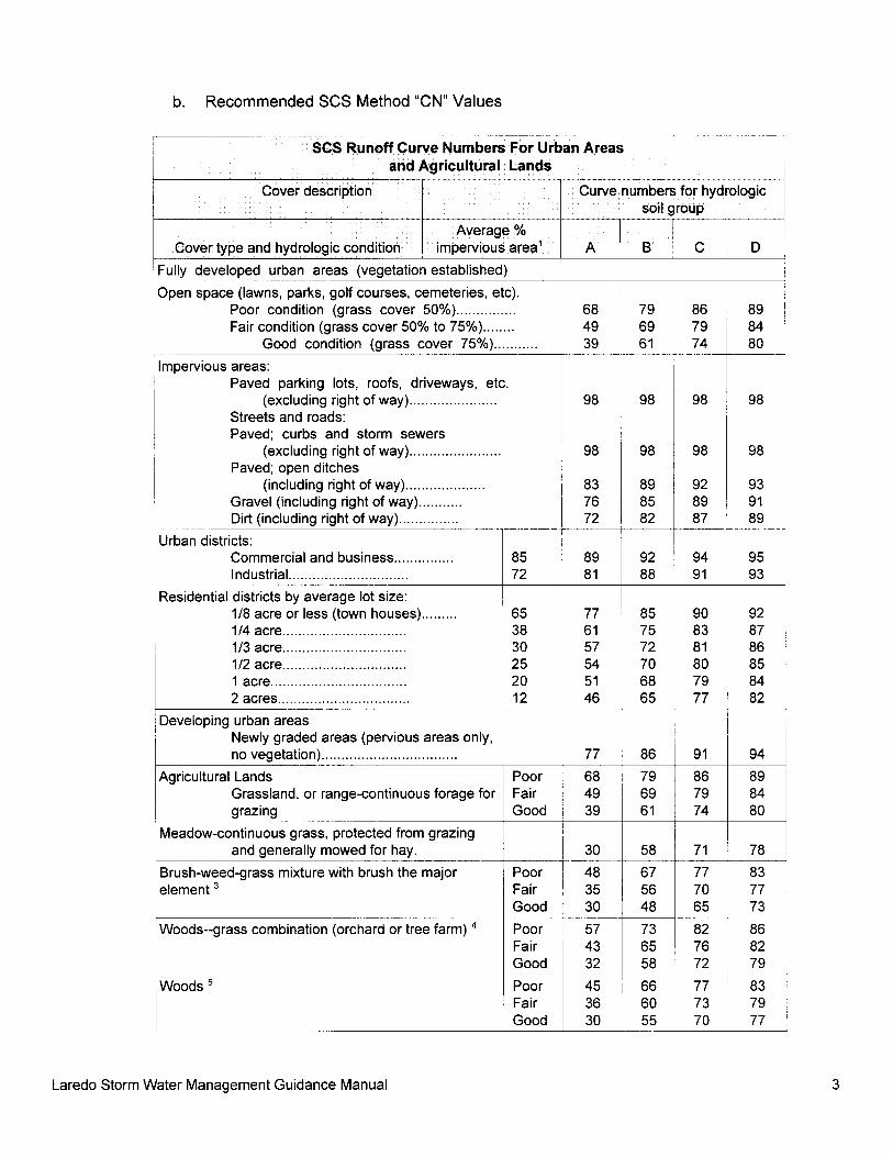
b. Recommended SCS Method "CN" Values
I Fully developed urban areas (vegetation established) - -. - .- --
Open space (lawns, parks, golf courses, cemeteries, etc). ............... ~ Poor condition (grass cover 50%)
........ I Fair condition (grass cover 50% to 75%) I ........... L-
Good condition (grass cover 75%)
Impervious areas: Paved parking lots, roofs, driveways, etc.
(excluding right of way) ...................... Streets and roads: Paved; curbs and storm sewers
(excluding right of way) .......................
- .-- - - -
SCS Runoff Curve Numbers For Urban Areas and Agricultural Lands
I
Paved; open ditches (including right of way) ....................
Gravel (including right of way) ........... ...............
- - -. Dirt (including right of way)
Urban districts: Commercial and business ............... Industrial ..............................
Cover description
Cover type and hydrologic condition
Residential districts by average lot size: ......... 118 acre or less (town houses)
............................. 114 acre..
............................. 113 acre.. 112 acre.. .............................
.................................. 1 acre 2 acres .................................
Average % impervious area1
Developing urban areas Newly graded areas (pervious areas only, no vegetation) ..................................
Agricultural Lands Grassland, or range-continuous forage for grazing
.- -. -
Meadow-continuous grass, protected from grazing and generally mowed for hay.
Brush-weed-grass mixture with brush the major element
Poor Fair Good
Curve numbers for hydrologic soil group
& ~ i
I
Good 30
A
Poor Fair
Woods--grass combination (orchard or tree farm)
B
Poor 57 Fair 43 Good 32
Woods
C
Fair Poor ~ ::
D
I Good 1 30
Laredo Storm Water Management Guidance Manual

Cover description 1 Curve numbers for hydrologic
Average %
Poor: less than 50 percent ground cover or heavily grazed with no mulch. Fair: 50 to 75 percent ground cover and not heavily grazed. Good: greater than 75 percent ground cover and lightly or only occasionally
grazed.
soil group I
Cover type and hydrologic condition 1 imperviois area1
Farmsteads--buildings, lanes, driveways and , surrounding lots.
Poor: less than 50 percent ground cover. Fair: 50 to 75 percent ground cover. Good: greater than 75 percent ground cover
Curve numbers shown were computed for areas with 50 percent woods and 50 percent grass (pasture) cover. Other combinations of conditions may be computed from the curve numbers for woods and pasture.
' The average percent impervious area shown was used to develop the composite curve numbers. Other assumptions are as follows: impervious areas are directly connected to the drainage system, impervious areas have a curve number of 98 and pervious areas are considered equivalent to open space in good hydrologic condition.
A
Poor: Forest litter, small trees and brush are destroyed by heavy grazing or regular burning.
Fair: Woods are grazed but not burned, and some forest litter covers the soil. Good: Woods are protected from grazing, and litter and brush adequately cover
the soil.
B I C i D
Source: Soil Conservation Service. TR-55: Urban Hvdroloav for Small Watersheds
59 74 82 86
3. ALLOWABLE MANNING'S "n" COEFFICIENTS
~~~e of channel and description 1 Minimum / Normal haximum
a. Brass, smooth 1 0.009 0.01 0 0.013
A. Closed Conduits Flowing Partly Full - -- --
A-I. Metal
, b. Steel I
I l
1. Lock bar and welded
2. Riveted and spiral
c. Cast iron 0.010 0.013 0.014 1
Laredo Storm Water Management Guidance Manual

I
/Type of channel and description 1 Minimum 1 Normal / Maximum
1 2. Uncoated 1 0.011 0.014 0.016 1 d. Wrought iron I I I
I
1 1. Black 0.012 0.014 0.015 1 I
i 2. Galvanized 0.013 0.016 0.017 1 1 e. Corrugated metal 1 I i 1 1 1. Subdrain 1 0.017 0.019 0.021 1 I 2. Storm Drain 1 0.021 0.024 0.030 1
A-2. Non Metal 1 1 a. Lucite 1 0.008 0.009 I 0.010 1
1 b. Glass ( 0.009 0.010 0.013
2. Mortar
1 c. Cement Lpp-
1 1. Neat, surface
d. Concrete I 1 1 I 1. Culvert, straight and free of debris 0.010 1 0.011 1 0.013
I
0.010 0.011
2. Culvert with bends, connections and some I 0.01 1 0.013 0.014 debris I
I I I
0.013
1 3. Finished 1 0.011 0.012 0.014 ~ I
I 4. Sewer with manholes, inlet, etc., straight 1 0.013 0.015 0.017 '
1 5. Unfinished, steel form 1 0.012 0.013 0.014
1 6. Unfinished, smooth wood form 1 0.012 0.014 0.016
1 7. Unfinished, rough wood form 0.01 5 0.017 0.020
1. Common drainage tile 1 0.011 0.013 0.017 1
1. Stave - - - -- -.
0.010 0.012 I 0.014 --- 7
I 2. Vitrified sewer 1 0.011 1 0.014 0.017
2. Laminated, treated 1 0.01 5 0.017
I 1 0.013 0.015 0.017 ' 3. Vitrified sewer with manholes, inlet, etc.
0.020 1
I 4. Vitrified subdrain with open joint 1 0.013 0.015 0.017
f. clay 1 I I
1 g. Brickwork 1 1 1 I
1. Glazed 1 0.011 0.013 , 0.015 I I 2. Lined with cement mortar / 0.012 1 0.015 0.017
I h. Sanitary sewers coated with sewage slimes, with i 0.012
0.013 0.016 bends and connections
i. Paved invert, sewer, smooth bottom 1 0.016 0.01 9 0.020
j. Rubble masonry, cemented
Laredo Storm Water Management Guidance Manual

1 B. Lined or Built-up Channels I I
I
Type of channel and description I -- - -- I I Minimum
1 B-1. Metal
1 a. Smooth steel surface ~ 1
Normal
I I 1. Unpainted 0.011 0.012 0.014 1
Maximum --A
I 2. Painted 0.012 0.013 i 0.017
1 b. Corrugated I 1 1 I 1 8-2. Nonmetal 1 i
1 a. Cement I / 1. Neat, surface 0.010 1 0.011 0.013
2. Mortar i 0.01 1 0.013 0.01 5
b. wood I i I
1. Planed, treated 1 0.010 0.012 0.014 1
2. Planed, creosoted 1 0.011 0.012 0.015
1 3. Unplaned 1 0.011 0.013 0.015
4. Plank with battens
5. Lined with roofing paper
c. Concrete ! I I 1. Trowel finish 1 0.011 0.013 0.015
2. Float finish / 0.013 0.015 0.016
I 3. Finished, with gravel on bottom 1 0.015 0.017 0.020 I I 4. Unfinished 1 0.014 0.017 0.020
1 5. Gunite, good section 1 0.016 0.019 0.023
1 1. Dressed stone in mortar
6. Gunite, wavy section
7. On good excavated rock ---
8. On irregular excavated rock
d. Concrete bottom float finished with sides of
1 2. Random stone in mortar 1 0.017 1 0.020 0.024
1 3. Cement rubble masonry, plastered I
0.016 0.020 1 0.024
0.018 0.022
0.017 0.020
0.022 0.027
I I 4. Cement rubble masonry 0.020 0.025 1 0.030
0.025 - - --i
I
I
1 e. Gravel bottom with sides of 1 1 1. Formed concrete 0.017 I 0.020 0.025
2. Random stone mortar - . .
3. Dry rubble or riprap
/ f. Brick I 1 1 I 1. Glazed
- . 0.01 1
- - ----- 0.012
1 _ -- 0.015
Laredo Storm Water Management Guidance Manual 6

I g. Masonry I I I I
~~~e of channel and description - -
1. Cemented rubble 0.017 0.025 0.030 1 2. Dry rubble 0.023 0.032 0.035
Minimum
h. Dressed ashler 0.013 0.015 0.017
1 i. Asphalt 1 I
Normal
1 1. Smooth 1 0.013 0.013
Maximum
1 2. Rough 1 0.016 0.016 I - / j. Vegetal lining 1 0.030 0.500
I C. Excavated or Dredged 1 I I I
/ a. Earth, straight and uniform I I I
1. Clean, recently completed 0.020
2. Clean, after weathering . -- - -
0.025
3. Gravel, uniform section, clean 0.022 0.025 0.030
1 4. With short grass, few weeds
b. Earth, winding and sluggish 1 1. No vegetation I 0.023 0.025 0.030
2. Grass, some weeds 0.025 0.030 0.033
3. Dense weeds or aquatic plants in deep channels
I I 4. Earth bottom and rubble sides 0.028 I 0.030 0.035
I 5. Stony bottom and weedy banks I 0.025 0.035 0.040 I 6. Cobble bottom and clean sides L-- - - - -- -
I c. Dragline-excavated or dredged
I r - I. NO vegetation
2. Light brush on banks - I d. Rock cuts I - - - -. -
1. Smooth and uniform 0.040
2. Jagged and irregular
e. Channels not maintained, weeds and brush uncut 1 I I
1. Dense weeds, high as flow depth
2. Clean bottom, rush on sides . -
0.040 0.050 0.080
3. Same, highest stage of flow 1 0.045 0.070 0.110 1 4. Dense brush high stage 1 0.080 1 0.100 0.140 1
D. Natural Streams 1 1 I D-1. Minor streams (top width at flood stage 4 0 0 ft) 0.250 0.030 1 0.033 1 a. Streams on plain
1. Clean. straight, full stage, no rifts or deep pools 0.025 ) 0.030 0.033 1 -- -- -.
Laredo Storm Water Management Guidance Manual

~~~e of channel and description 1 Minimum 1 Normal 1 Maximum ~ I I 2. Same as above, but more stones and weeds 1 0.030 , 0.035 0.040 1
3. Clean, winding, some pools and shoals / 0.033 1 0.040 0.045
I 4. Same as above, but some weeds and stones 1 0.035 0.045 0.050
5. Same as above, lower stages, more ineffective 0.050 slopes and sections
I I 6. Same as 4, but more stones
7. Sluggish reaches, weedy, deep pools I 0.050 0.070 1 0 0 8 q - --
8. Very weedy reaches, deep pools, or floodways 0.075 0.100 0.150 with heavy stand of timber and underbrush
I I
b. Mountain streams, no vegetation in channel, banks i usually steep, trees and bush along banks submerged at high stages 1
5. Same as above, but with flood stage reaching 0.100 branches
1. Bottom: gravels, cobbles, and few boulders 0.030 - -- -- - - - - -
0.040 0.050
2. Bottom: cobbles with large boulders 1 0.040 0.070
Pasture, no brush -- -- . - --- -
1. Short grass 0.025 0.030 0.035
2. High grass I _
0.030 0.035 0.050
b. Cultivated areas
Laredo Storm Water Management Guidance Manual
-- - - -- - - -
- 1. No crop -- --
I 2. Mature row crops - -- - r-
3. Mature field crops I -- --
c. Brush
k-- 1. Scattered brush, heavy weeds
2. Light brush and trees, in winter -
3. Light brush and trees, in summer -
4. Medium dense brush, in winter
I 5. Medium dense brush, in summer &--_ - - - - -- - -- --
- d. Trees
- -- - - -- ---
1. Dense willows, summer straight --
0.110 0.01 5 0.200
I 2 Cleared land with tree stumps, no sprouts 0.030 ' 0.040 0.050
1 3. Same as above, but with heavy growth of 0.050 0.060 0.080
4. Heavy stand of timber, a few down trees, little 0.100 0.120 undergrowth, flood stage below branches
0.020
0.025
0.030
0.035
0.035
0.040
0.030 0.040 - ---
0.035 I 0.045
0.040 0.050
I
+ - -
0.050 0.070
0.050 0.060 - -
0.060 0.080 v- --
0.045 0.070 0.110 I - ---
0.070 0.100 -
0.160

iType of channel and description 1 Minimum ! Normal 1 Maximum
' D-3 Major streams (top width at flood stage >lo0 ft). I The "n" value is less than that for minor streams of I similar description, because banks offer less I effective resistance.
I a. Regular section with no boulders or brush 0.025 - 0.060 1 / b. Irregular and rough section 1 0.035 - 1 0 . 1 0 0 !
Laredo Storm Water Management Guidance Manual

4. FREEBOARD AND SUPERELEVATION REQUIREMENTS
a. Freeboard: Adequate channel freeboard shall be provided for the 100-year storm in reaches flowing at critical depth by using Equation 2 or the elevation of the energy grade line, whichever is less.
where, HFB = Freeboard height, ft V = Velocity, ft/sec d = Depth of flow, ft
Freeboard shall be in added to superelevation, standing waves and/or other water surface disturbances. Concrete side slopes shall be extended to provide freeboard. Freeboard shall not be obtained by the construction of levees. Minimum freeboard for all channels shall be 1' above the 100-year water surface elevation.
b. Superelevation: Superelevation of the water surface shall be determined at all horizontal curves which deviate more than 45 degrees off the projected centerline. An approximation of the superelevation at a channel bend can be obtained from the following equation:
where h = Superelevation, ft V = Flow velocity, ft/sec T,= Top width of channel, ft r, = Centerline radius of curvature, ft g = Acceleration due to gravity, ft/sec2
The freeboard shall be measured above the superelevation water surface.
Laredo Storm Water Management Guidance Manual

5. STORM WATER RUNOFF CALCULATION METHODS
-- Storm Runoff Calculation Methods
Contributing Area Runoff Methods*
Less than 100 Acres Rational or VRlM SCS TabularlGraphical
I 100 Acres-400 Acres SCS TabularlGraphical 1 TR-20 or HEC-1
400 Acres - 15 mi2 SCS TR-20 or HEC-1 ~ Greater than 15 mi2 SCS TR-20 or HEC-1 ~ ' VRIM, Variable Rainfall Intensity Method
SCS, TabularIGraphical and TR-20 Methods 3 It is recommended that the hand calculated SCS Tabular Method not be used for
areas greater than 400 acres due to the rigorous nature of the calculations and likelihood of error. Other model methodologies may be used if pre-authorized by the City Engineer.
.- -
6. DESIGN GUIDELINES FOR WATER QUALITY CONTROL BASINS
Storm water can have significant impact on the water quality of Laredo's creeks and on the Rio Grande. Treatment of this storm water by filtration and/or sedimentation improves water quality by removing suspended particulate matter and associated constituents such as bacteria, nutrients and metals.
Filtration systems are the primary water quality control structures. In order to ensure the long-term effectiveness of these systems, it is necessary to protect the filter media from excessive sediment loading. Typically a sediment trapping structure is required to be located prior to the filtration basin.
The sedimentation basin consists of an inlet structure, outlet structure and basin liner. The sedimentation basin design should maximize the distance from where the heavier sediment is deposited near the inlet to where the outlet structure is located. This will improve basin performance and reduce maintenance requirements.
a. Water Quality Volume
The primary control strategy for water quality basins is to capture and isolate the "first flush" volume of storm water runoff for treatment. This "first flush" volume is outlined in section 24.59.5.4.1 of the Storm Water Management Ordinance for the three water quality treatment options. The water quality volume must consist of runoff from all impervious surfaces such as roadways, parking areas and roof tops; additionally, runoff from all pervious areas which provide contributing drainage to impervious areas must also be included in the water quality volume. Water quality treatment is not required for runoff from lands left in their natural
Laredo Storm Water Management Guidance Manual

state, e.g., greenbelts and open spaces; natural state may include areas restored to natural state. Runoff from these areas must be routed around the water quality basin or it must be included in the water quality volume. Off-site contributing drainage should be routed around the water quality basin. If this is not done, off- site contributing areas must be included in the water quality volume.
b. Storm Water Quality Treatment Options - Off-Line, On-Line and Wet Detention
I. Off-Line detention
Off-line detention is the capture and isolation of the water quality volume typically achieved by using isolation and diversion baffles and weirs. A typical approach for achieving isolation of the water quality volume is to construct an isolation/diversion weir in the storm water channel such that the height of the weir equals the height of water in the water quality basin when the entire water quality volume is being held. When additional runoff greater than the water quality volume enters the storm water channel it will spill over the isolation/diversion weir and mixing with the already isolated water quality volume shall be minimal.
Because travel time from distant contributing areas reduces the effectiveness of the water quality volume in capturing all of the first flush runoff, a maximum contributing drainage area of 50 acres per filtration basin system is recommended.
ii. On-Line detention:
On-line detention consists of providing the water quality volume within the storm water management facility, below the storm water outflow invert. This volume is to be discharged slowly (>24 hrs ) to increase the potential for sedimentation.
iii. Wet Detention
Wet detention is a treatment system that utilizes water-tolerant vegetation and which removes pollutants through settling, absorption by soils, and nutrient uptake by vegetation, and in which a design water pool is normally maintained which has a capacity to provide extended detention for the required storm water treatment volume above a permanent water level.
Laredo Storm Water Management Guidance Manual

7. EASEMENTS
All channel easements should be a minimum of 15' on either side of the channel measured from the 100 year water surface elevation plus 1' of freeboard. All closed drainage easements shall meet the following minimum standards, unless special circumstances warrant additional or reduced easements, as determined by the City Engineer:
36" and under I 15' i
I
Pipe Size I
(in inches)
I 42" through 54" 1 20' ~ I
I
Minimum Easement Width (in feet) --I
~ 60" through 66" ~ 25' ~
8. RETAINING WALL DESIGN
72" and above
Retaining walls shall be designed using the best available information and current acceptable level of practice in the field of structural engineering. The design should refer to the appropriate ACI manuals for concrete design and ASHTO standards for anticipated loadings where applicable.
30'
Laredo Storm Water Management Guidance Manual

SECTION 2
BEST MANAGEMENT
PRACTICES

The Best Management Practices (BMPs) in this manual provide environmental protection measures for the majority of situations experienced on a construction site. It is intended to provide the ContractorlEngineer with information concerning the application and effectiveness of various BMPs. It is important to note that this manual does not provide an exhaustive list of BMPs. There are many new publications and studies being conducted into the designing and testing of new BMPs. If there is any unique construction activity not covered by this manual, other design manuals should be reviewed.
The structural BMPs contained within this manual, in large part, address the protection of the environment from contaminants already borne by storm water runoff. The following is a list of Preventive MaintenanceIGood Housekeeping activities that, if followed, limit the potential for pollutants to be present in the environment and available for uptake by runoff. These Preventive MaintenanceIGood Housekeeping activities should be followed in conjunction with the structural BMPs to limit the possibility of storm water contamination:
Preventive Maintenance
Do not connect floor drains in potential pollutant source areas to storm drains, surface water conveyance systems, receiving water bodies, or to the ground.
Cover and contain materials, equipment, waste and compost piles that could cause leachate contamination of storm water.
Conduct all oily parts cleaning, steam cleaning, or pressure washing of equipment or containers inside a building, or on an impervious contained area, such as a concrete pad. These areas should be drained to appropriate BMPs andlor the sanitary sewer system where allowed by the local sewer authority.
Use drip pans to collect leaks and spills from equipment and vehicles that are stored outside.
For the storage of liquids use containers, such as steel and plastic drums, that are rigid and durable, corrosion resistant to the weather and fluid content, non-absorbent, water tight, rodent-proof, and equipped with a close-fitting cover.
For the temporary storage of solid wastes contaminated with liquids or other potential pollutant materials use dumpsters, garbage cans, drums and comparable containers, which are durable, corrosion resistant, non-absorbent, non-leaking, and quipped with either a solid cover or screen cover to prevent littering. If covered with a screen, the container must be stored under a lean-to or equivalent structure.
Where feasible store potential storm water pollutant materials inside a building or under a cover andlor containment.
Minimize use of toxic cleaning solvents, such as chlorinated solvents, and other toxic chemicals.
Laredo Storm Water Management Guidance Manual

Recycle waste materials such as solvents, coolants, oils, degreasers, and batteries to the maximum extent feasible.
Empty drip pans immediately after a spill or leak is collected in an uncovered area.
Stencil warning signs at storm water catch basins and drains indicating not to discharge waste to a receiving water body.
Good Housekeeping:
Promptly contain and clean-up solid and liquid pollutant leaks and spills, including oils, solvents, fuels, and dust on any exposed soil, vegetation, or paved area.
Sweep paved material handling and storage areas monthly, or more frequently, if needed, for the collection and disposal of dust and debris that could contaminate storm water.
Do not hose down pollutants from any area to the ground, a storm drain, conveyance ditch, or receiving water.
Clean oils, debris, sludge, etc. from all BMP systems, including catch basins, settlingldetention basins, oillwater separators, boomed areas, and conveyance systems, regularly.
Promptly repair or replace all substantially cracked or otherwise damaged paved process, secondary containment, high-intensity parking and any other drainage areas, which can be contaminated by pollutant material leaks or spills.
Promptly repair all leaking connections, pipes, hoses, valves, etc. which can contaminate storm water.
Clean up pollutant liquid leaks and spills in impervious uncovered containment areas at the end of each working day.
Use solid absorbents, e.g., clay and peat absorbents and rags for cleanup of liquid spillslleaks, where practicable.
Laredo Storm Water Management Guidance Manual

IntentionallyBlank

Laredo Storm Water Management Guidance Manual 22
APPLICATIONS
POLLUTANT REMOVAL
IMPLEMENTATIONREQUIREMENTS
BMP -
INTERCEPTOR SWALE
1
Perimeter Control
Slope Protection
HI Sediment
LO Oil & Grease
LO Nutrients & Toxics
HI Floatables
MED Other ConstructionWastes
MED Capital Costs
MED Maintenance
LO Training
HI Suitability to slopes>5%
DESCRIPTIONAn interceptor swale is a trapezoidal or parabolic channel which collects waterand directs it to a desired location. The interceptor swale can be lined withnative vegetation or a protective lining, depending upon the slope and designvelocities.
APPLICATIONSInterceptor swales are used to reduce the amount and speed of flow and conveyit to a stabilized outfall. Placement at the top of a sloping disturbed area keepsrunoff from crossing disturbed areas where there is a high risk of erosion.Placement at the toe of slopes from disturbed areas allows the collection ofsediment-laden runoff for treatment prior to discharge from the site.
Interceptor swales are commonly installed prior to commencement of major soildisturbing activities. Temporary swales are useful in protecting specific areas,such as staging, storage or fueling areas, and smaller disturbed areas duringphased construction.
Vegetated interceptor swales are also effective as permanent storm watercontrols. To remain in place as permanent controls, the swales must be de-signed to handle post-construction runoff, must be permanently stabilized, andshould be routinely inspected and maintained.
DESIGN CRITERIA� Depth of flow in the swale shall be based on a 2-year design storm peak
flow. Positive overflow must be provided to accommodate larger storms.� Side slopes of the swale shall not exceed 3:1.� Minimum design channel freeboard shall be 6 inches.� The minimum required channel stabilization shall be grass, erosion control
mats, or mulching. For grades in excess of 2 percent or velocities exceed-ing 6 feet per second, stabilization consisting of high velocity erosion controlmats, or a 3-inch layer of crushed stone or riprap is required. Velocitiesexceeding 8 feet per second are discouraged.

Laredo Storm Water Management Guidance Manual 23
INTERCEPTOR SWALEDESIGN CRITERIA (CONT.)
¨ Swales must be designed for flow capacity based on Manning�s Equation to ensure proper channel section.¨ Check dams can be used to reduce velocities in steep swales. Refer to the Check Dam BMP sheet for
additional information.¨ Possible impacts to upstream or downstream stream reaches should be considered.¨ Swales must maintain a positive grade to an acceptable outlet.¨ Swales which will remain in place longer than 15 days should be stabilized.¨ Swales should remain in place until the area being protected has been permanently stabilized.
MAINTENANCE REQUIREMENTSInterceptor swales must be inspected once each week and following a storm event of 0.5 inches or greater.Repairs to the swales must be made promptly to ensure continued protection of the site.
ADVANTAGES
+ Simple and effective for channeling runoff away from areas subject to erosion
+ Can handle flows from large drainage areas
+ Inexpensive
DISADVANTAGES
- Cause erosion and sediment transport due to concentrated flows if constructed improperly
- Discourages vegetation growth if velocities too high
- Require ongoing maintenance, inspections and repairs

Laredo Storm Water Management Guidance Manual 24
APPLICATIONS
POLLUTANT REMOVAL
IMPLEMENTATIONREQUIREMENTS
BMP -
DIVERSION DIKE
DESCRIPTIONA diversion dike is a ridge constructed of earth which is used to protect workareas from up slope runoff and to divert sediment-laden runoff to stabilizeddischarge outlets. The dike consists of compacted soil stabilized either withnative vegetation for low velocity flows or with riprap or erosion control mats forhigher velocity flows.
APPLICATIONSDiversion dikes are used in construction areas to control erosion, sedimentationor flood damage. Placement at the top of a sloping disturbed area preventsrunoff from crossing disturbed areas where there is a high risk of erosion.Placement at the toe of slopes from disturbed areas allows the collection ofsediment-laden runoff for treatment prior to discharge from the site.
Diversion dikes are commonly installed at the perimeter of construction siteswhich are subject to large quantities of runoff from neighboring sites. Used incombination with drainage swales, the diversion dike can be quickly installedwith a minimum of equipment and costs, using the swale excavation as the dike.Use of diversion dikes can reduce the costs associated with structural controlsnot only by reducing the quantity of flow but also by directing runoff to a centrallocation for treatment.
DESIGN CRITERIA¨ The maximum contributing drainage area should be less than 10 acres
depending upon site conditions.¨ The dike shall have capacity for the 2-year design storm peak flow.¨ The maximum width of the flow at the dike shall be 20 feet.¨ Side slopes of the diversion dike shall not exceed 3:1.¨ Minimum width of the embankment at the top shall be 2 feet.¨ Minimum embankment height shall be 18 inches as measured from the toe
of the slope.
Perimeter Control
Slope Protection
HI Sediment
LO Oil & Grease
LO Nutrients & Toxics
MED Floatables
MED Other ConstructionWastes
MED Capital Costs
MED Maintenance
LO Training
HI Suitability to slopes>5%
2

Laredo Storm Water Management Guidance Manual 25
DIVERSION DIKE
DESIGN CRITERIA (cont.)¨ Where velocities are less than 6 feet per second, the minimum stabilization for the dike and adjacent flow
areas is grass, erosion control mats, or mulch. Where the velocities exceed 6 feet per second, crushedstone, riprap or high velocity erosion control mats should be used. Velocities greater than 8 feet persecond are discouraged.
¨ Possible impacts to upstream or downstream conditions should be considered.¨ The flow line at the dike must be maintained on a positive grade to an acceptable outlet.¨ Dikes should remain in place until the area being protected has been permanently stabilized.¨ Due to potential interference with movement of construction equipment, dike locations should be carefully
considered prior to installation.
MAINTENANCE REQUIREMENTSDiversion dikes must be inspected once each week and following a storm event of 0.5 inches or greater.Repairs must be made promptly to ensure continued protection of the site.
ADVANTAGES
+ Simple and effective for channeling runoff away from areas subject to erosion
+ Inexpensive due to readily available construction materials
DISADVANTAGES
- Effectiveness limited by improper design and construction
- Require ongoing maintenance, inspections and repairs

Laredo Storm Water Management Guidance Manual 26
APPLICATIONS
POLLUTANT REMOVAL
IMPLEMENTATIONREQUIREMENTS
BMP -
PIPE SLOPE DRAIN
Slope Protection
MED Floatables
LO Oil & GreaseSedimentNutrients & ToxicsOther ConstructionWastes
HI Capital Costs
HI Maintenance
LO Training
HI Suitability toslopes >5%
3
DESCRIPTIONA pipe slope drain is a temporary pipe installation which conveys water down adisturbed slope to the outfall. Pipe slope drains are typically constructed fromflexible piping with stabilized areas at the top and toe of the slope. Often atemporary headwall is constructed at the top of the slope to anchor the pipe andprevent undercutting.
APPLICATIONSPipe slope drains are used on sites with long, unstabilized, steep slope areaswhich are disturbed and subject to erosion from sheet flow. Interceptor swalesor diversion dikes are commonly used to divert flow into the pipe slope drain.Pipe slope drains can service relatively large drainage areas, but do not provideany pollutant removal. Discharges from pipe slope drains must, therefore, bedirected to a treatment BMP prior to discharge from the site.
Pipe slope drains are also effective as permanent storm water controls. Toremain in place as permanent controls, the drains must be designed to handlepost-construction runoff, must be permanently stabilized, and should be routinelyinspected and maintained. Permanent pipe slope drains are often installedbelow grade.
DESIGN CRITERIA¨ A standard corrugated metal pipe with a prefabricated flared end section
and integral toe plate which extends a minimum of 6 inches from the bottomof the end section may be used as the entrance. The grade of the entranceshall not exceed 3%.
¨ The berm/diversion dike at the entrance shall have a minimum height of thepipe diameter plus 6 inches and a minimum width of 3 times the pipe diam-eter.
¨ Watertight collars or gasketed watertight fittings shall be used to connect allsections of the pipe slope drain.
¨ All sediment-laden runoff conveyed by the pipe slope drain shall be directedto a sediment trapping facility.

Laredo Storm Water Management Guidance Manual 27
PIPE SLOPE DRAIN
DESIGN CRITERIA (CONT.)
¨ Maximum drainage area for individual pipe slope drains shall be 5 acres. For areas larger than 5 acres,multiple pipe slope drains shall be used.
¨ Temporary pipe slope drains are to be sized to accommodate runoff flows equivalent to a 10-year storm ascalculated using the Rational Method and Manning�s Equation, but in no case shall pipes be sized smallerthan is shown in the following table:
Minimum Pipe Size Maximum Contributing Drainage Area
12" 0.5 Acres
18" 1.5 Acres
21" 2.5 Acres
24" 3.5 Acres
30" 5.0 Acres
¨ Both the inlet and outfall of the pipe slope drain should be properly stabilized. Grass can typically be used forthe inlet, but the outlet, at a minimum, will require the use of crushed stone or riprap to protect against thehigh velocities.
¨ Drains must be located away from construction areas to avoid damage from construction equipment.¨ The area upstream of the pipe slope drain typically must be graded to direct flow into the inlet.
MAINTENANCE REQUIREMENTSPipe slope drains must be inspected once each week and following every storm event of 0.5 inches or greater.Damage to joints or clogging of pipe must be repaired promptly to ensure continued protection of the site. Wherethe diversion dike at the top of the slope has eroded, the dike must be reinforced with sandbags or a concretecollar to prevent failure. Erosion around the pipe drain should be stabilized with erosion control mats, crushedstone, riprap, concrete pavement, or other acceptable methods.
ADVANTAGES
+ Reduces or eliminates erosion by transporting water down steep slopes or by draining saturated soils
+ Easy to install and require little maintenance if installed properly.
DISADVANTAGES
- May require ongoing maintenance, inspections and repairs
- Requires stabilization of the area disturbed by installation to prevent erosion
- May clog during large storm event

Laredo Storm Water Management Guidance Manual 28
APPLICATIONS
POLLUTANT REMOVAL
IMPLEMENTATIONREQUIREMENTS
BMP -
VEGETATION
Slope Protection
Channel Protection
Temporary Stabilization
Permanent Stabilization
HI Sediment
MED Nutrients & Toxics
LO Oil & GreaseFloatablesOther ConstructionWastes
HI Suitability toslopes >5%
MED Capital CostsMaintenance
LO Training
4
DESCRIPTIONThe use of vegetation as a Best Management Practice consists of installinggrasses or groundcovers to prevent erosion of topsoil. Vegetation can be usedalone or as a protective lining for other BMPs.
APPLICATIONSVegetation effectively reduces erosion from swales, stock piles, berms andalong roadways and therefore has a wide range of applicability. Leaving vegeta-tive strips around a site is an excellent means of protecting an area disturbed byutility or site development construction.
Vegetation has applicability for both temporary and permanent erosion control.Temporarily vegetating stockpiles may have a higher initial cost, but, dependingon the length of time the cover will remain in place, may be cost-effective whencompared to the expense of maintaining tarps or covers.
Vegetation is not an appropriate erosion control measure in areas which aresubject to heavy pedestrian or vehicular traffic.
DESIGN CRITERIA¨ Interim or final grading must be completed prior to seeding. Steep slopes
should be eliminated.¨ Other erosion control structures, such as dikes, swales, diversions, etc.,
should be installed prior to seeding.¨ Groove or furrow slopes steeper than 3:1 on the contour line before seeding.¨ Provide 4-6 inches of topsoil over rock, gravel or otherwise unsuitable soils.
The seed-bed should be well pulverized, loose and uniform.¨ Use only high quality, USDA certified seed.

Laredo Storm Water Management Guidance Manual 29
VEGETATION
DESIGN CRITERIA (CONT.)
¨ Select an appropriate species or species mix adapted to local climate, soil conditions and season accordingto the following table. Consult with the local office of the U.S. Soil Conservation Service (SCS) or other localsources for selection of proper species and application techniques.
¨ The seeding application rate should be in accordance with that recommended by the SCS or other localexpert.
¨ Fertilizer should be applied according to manufacturer�s recommendation with proper spreading equipment.The typical application rate for a 10-10-10 grade fertilizer is 700-1000 lb/acre. DO NOT APPLY EXCESSFERTILIZER.
¨ If hydro-seeding, do not mix seed and fertilizer more than 30 minutes prior to application.¨ Apply seed using a cyclone seeder, seed drill, cultipacker or hydroseeder.¨ Provide adequate hydration to aid in establishment of vegetation.¨ Use appropriate mulching techniques where necessary.
MAINTENANCE REQUIREMENTSProtect newly seeded area from excessive runoff and traffic until vegetation is established. A watering andfertilizing schedule should be developed and implemented to assist in establishment of the vegetation. Onceestablished, maintain as necessary to address erosion.
DISADVANTAGES
- Erosion and sediment transport from concentrated flows can occur if seed does not take
- Significant watering may be required during dry season to establish vegetation
ADVANTAGES
+ Simple and effective stabilizing areas
+ Inexpensive

Laredo Storm Water Management Guidance Manual 30
APPLICATIONS
POLLUTANT REMOVAL
IMPLEMENTATIONREQUIREMENTS
BMP -
MULCHING
Slope Protection
Temporary Stabilization
HI Sediment
LO Oil & Grease
Nutrients & Toxics
Floatables
Other ConstructionWastes
MED Capital Costs
Maintenance
LO Training
Suitability toslopes >5%
5
DESCRIPTIONMulching is the application of a protective layer of material on bare areas toreduce erosion caused by the impact energy of rainfall. The types of materialwhich can be used for mulching include organic materials such as hay, woodchips, or pine bark and inorganic materials.
APPLICATIONSMulching is used for either temporary or permanent stabilization of areas whichhave been cleared of vegetation. Mulching is also used to protect areas whichhave been seeded until the grass has established itself. Both the risk of erosionand moisture loss due to the action of rain, wind and sunlight are reduced by theapplication of mulch. In addition, mulch slows runoff from disturbed areas andallows for the deposition of previously entrained sediments.
Mulching can be used alone or in combination with other techniques. Netting orother means of anchoring the mulch may be used to assist in stabilization ofdisturbed areas. Some manufacturers produce pre-packaged mulching material(for instance, hay inside biodegradable netting) which reduce the labor require-ments for placing mulch.
DESIGN CRITERIA¨ If using a prepackaged mulch material, follow the manufacturers installation
instructions.¨ The selection of mulch material depends largely on the slope, climate, and
soil type. Cost and availability of materials are also considerations. Strawor hay are recommended due to low cost, wide availability and biodegrad-ability.
¨ Mulch should be applied uniformly and evenly over areas without concen-trated water flow.
¨ Typical application rates are approximately two tons per acre of dry straw orhay. For other materials coverage should be based on the manufacturersinstructions or such that 25% of the soil is visible through the mulching.
¨ On slopes exceeding 3-5%, anchoring may be required to keep the mulch inplace.
¨ Organic mulches typically biodegrade over time. Reapplication may berequired to provide adequate protection.

Laredo Storm Water Management Guidance Manual 31
MULCHING
MAINTENANCE REQUIREMENTSMulched areas must be inspected weekly and following storm events of 0.5 inches or greater. Thin or bare areasshould be covered with fresh mulch material. High traffic areas will require application of fresh mulch on a routinebasis to provide adequate protection.
ADVANTAGES
+ Provides immediate protection to exposed soils.
+ Retains moisture which may reduce watering requirements for vegetation establishment.
+ Does not require removal due to natural biodegradation.
+ Inexpensive.
DISADVANTAGES
- May delay germination of seeds due to reduction in soil surface temperature.
- May be easily blown or washed away if not properly anchored.
- Mulch materials such as wood chips may absorb nutrients required for plant growth.
- Mulch materials that are washed off may clog other site BMPs.

Laredo Storm Water Management Guidance Manual 32
APPLICATIONS
POLLUTANT REMOVAL
IMPLEMENTATIONREQUIREMENTS
BMP -
EROSION CONTROL MATS
DESCRIPTIONErosion control mats are manufactured geomembranes or biodegradable fabricswhich are placed over disturbed areas to provide protection from erosion. Awide variety of vendors produce erosion control mats to promote vegetationestablishment and protect banks from high velocity flows.
APPLICATIONSErosion control mats provide temporary or permanent stabilization protection tobarren or disturbed areas. Erosion control mats are particularly helpful in areasthat are difficult to stabilize such as steep slopes, drainage swales, embank-ments, or high pedestrian traffic areas.
DESIGN CRITERIA¨ Erosion control mats should be installed in accordance with the
manufacturer�s instructions.¨ After installation the matting should be checked to ensure that the matting is
in uniform contact with the soil, that lap joints are well secured, and thatanchor staples are flush with the ground.
MAINTENANCE REQUIREMENTSInstallations of erosion control matting must be inspected weekly and followingsignificant storm events of 0.5 inches or greater. Missing or loose mats must bereplaced or reanchored promptly to ensure continued protection of the site.
Slope Protection
Sediment Trapping
Temporary Stabilization
Permanent Stabilization
MED Sediment
LO Oil & Grease
LO Nutrients & Toxics
LO Floatables
LO Other ConstructionWastes
HI Capital Costs
MED Maintenance
MED Training
MED Suitability toslopes >5%
6

Laredo Storm Water Management Guidance Manual 33
EROSION CONTROL MATS
ADVANTAGES
+ Relatively inexpensive for certain applications.
+ Easy to install.
+ Wide variety of materials available for many uses.
DISADVANTAGES
- Effectiveness is highly dependent upon selection of proper material and correct installation.

Laredo Storm Water Management Guidance Manual 34
APPLICATIONS
POLLUTANT REMOVAL
IMPLEMENTATIONREQUIREMENTS
BMP -
PERMANENT STRUCTURAL CONTROLS
DESCRIPTIONPermanent structural controls consist of gabions, retaining walls, riprap, non-bioderadeable geotextile and geoweb products. These controls are designed toprovide permanent stabilization of slopes and channels that will continue toexperience erosive velocities following construction. These controls can bedesigned to provide erosion protection (gabion mats, rock riprap, geotextile, etc.)and/or structural slope control (gabions, retaining walls, geo web, etc.).
APPLICATIONSPermanent erosion control devices should only be used to stabilize areas with ahigh potential for erosion at the conclusion of the contruction phase. Areas witha high potential for erosion include any channel section with velocities greaterthan 6 fps as well as localized obstructoins to the natural channel flow regime(crossings, culverts, discharge pipes, etc.) that may cause localized erosion.Due to the complex nature of the flow regime requiring permanent structuralcontrols, these controls should be engineered.
DESIGN CRITERIA¨ Manufacturers design guidelines should be followed in all permanent
structural control applications.¨ Permanent structural controls may need to be provided at localized obstruc-
tions to the flow regime.¨ Design of structural slope controls should consider area soils, wall height
and groundwater conditions and should be engineered.¨ When using permanent erosion structural controls the channel side slopes
shall not exceed 3:1.¨ Anchoring of the permanent control is critical as undermining of the founda-
tion and washout of sediments at the edges can cause catastrophic failure ofthe structural control.
¨ Impacts to upstream and downstream conditions should be considered.¨ Check dams may be used to reduce velocities in steep swales. Refer to the
Check Dam fact sheet for additional information.7
HI Capital Costs
MED Maintenance
Training
HI Suitability to slopes>5%
LO Oil & Grease
I Sediment
Nutrients & Toxics
FloatablesOther ConstructionWastes
Perimeter Control
Slope Protection
Channel Protection
Temporary Stabilization
Permanent Stabilization

Laredo Storm Water Management Guidance Manual 35
DESIGN CRITERIA (cont.)
¨ Anchoring of the permanent controls is critical as undermining of the foundation and washout of sediments atthe edges can cause catastrophic failure of the structure.
¨ Swales must be designed for flow capacity based on Manning�s Equation to ensure proper channel section.¨ Check dams can be used to reduce velocities in steep swales. Refer to the Check Dam fact sheet for addi-
tional information.¨ Impacts to upstream or downstream conditions should be considered.¨ Swales must maintain a positive grade to an acceptable outlet.
MAINTENANCE REQUIREMENTSPermanent structural controls must be inspected annually to ensure that the BMP is providing adequate protectionand has not been washed away or undermined by flows to ensure continued protection of the site. Any damageto the permanent structural control should be repaired immediately
ADVANTAGES
+ Can provide structural stability to steep channel slopes.
+ Can provide long term effective erosion and slope control.
+ Able to handle high velocity flows
DISADVANTAGES
- Cause erosion and sediment transport due to concentrated flows if constructed improperly.
- Discourages vegetation growth if the velocities are too high
- Requires ongoing maintenance, inspections and repairs.
- Expensive to design and construct.
- May require additional state and federal permitting.
PERMANENT STRUCTURAL CONTROLS

Laredo Storm Water Management Guidance Manual 36
APPLICATIONS
POLLUTANT REMOVAL
IMPLEMENTATIONREQUIREMENTS
BMP -
SILT FENCE
Perimeter Control
Slope Protection
Sediment Trapping
HI Sediment
MED Floatables
LO Oil & GreaseNutrients & ToxicsOther ConstructionWastes
MED Capital Costs
HI Maintenance
LO Training
MED Suitability toslopes >5%
8
DESCRIPTIONSilt fencing consists of filter fabric stretched between support posts to catchsheet flow drainage from disturbed areas. The filter fabric is supported bychicken wire or other backing material and is toed in with an anchor trench at thebase. Properly designed and installed silt fence can be very effective andeconomical because it can be re-located on the current construction site, and/orre-used at other construction sites.
APPLICATIONSSilt fences are used to treat overland, non-concentrated flows from disturbedareas. Silt fences are used most often as perimeter control for both site devel-opment projects and linear (roadway) projects. Most effective with coarse tosilty soil types, silt fences are subject to clogging when used with clay soil types.Silt fences are not appropriate for treating concentrated flows.
DESIGN CRITERIA¨ Silt fences should be located along a line of constant elevation where
possible.¨ The maximum slope permissible adjacent to the fence is 1:1.¨ Maximum distance of flow to the silt fence should be less than 200 feet.¨ Maximum concentrated flow to the silt fence should be no greater than 1
cubic foot per second per 20 feet of fence.¨ If 50% or less of the soil to be contained, by weight, passes the U.S.
Standard Sieve No. 200, select the equivalent opening size (EOS) to retain85% of the soil.
¨ The maximum opening size shall be 70 (#70 sieve) and the minimumopening size shall be 100 (#100 sieve).
¨ If 85% or more of the soil to be contained, by weight, passes the U.S.Standard Sieve No. 200, silt fencing shall not be used due to cloggingpotential.
¨ Provide sufficient room between the silt fence and other obstructions for theoperation of the sediment removal equipment to properly maintain the fence.
¨ The ends of the fence should be turned upstream to prevent bypass ofsediment-laden flow.

Laredo Storm Water Management Guidance Manual 37
SILT FENCE
MAINTENANCE REQUIREMENTSSilt fencing runs must be inspected weekly and following significant storm events of 0.5 inches or greater.Routine removal of sediment must be performed to ensure continued successful operation of the fencing. Thesediment should be removed when it reaches a depth of approximately one-half the height of the fence. If thefabric becomes clogged, either clean or replace the filter fabric.
ADVANTAGES
+ Removes sediment and prevents downstream damage from sediment deposits.
+ Reduces the speed of runoff flow.
+ Minimal clearing and grubbing required for installation.
+ Inexpensive.
DISADVANTAGES
- May result in failure from improper choice of pore size in the filter fabric or improper installation.
- Should not be used in streams.
- Is only appropriate for small drainage areas with overland flow.
- Frequent inspection and maintenance is necessary to ensure effectiveness.

Laredo Storm Water Management Guidance Manual 38
APPLICATIONS
POLLUTANT REMOVAL
IMPLEMENTATIONREQUIREMENTS
BMP -
DESCRIPTIONA hay bale dike is a temporary barrier constructed of hay bales which have beenanchored in place. Most commonly, wooden stakes or steel rebar is used toanchor the straw bales. Hay bales are used either to intercept and redirect flowor to serve as a filtration device.
APPLICATIONSHay bale dikes are typically only used on small residential sites since they arelimited to controlling runoff from small drainage areas on relatively flat slopes.
Hay bales can also be used as check dams but are limited to small water-courses due to problems with adequately securing the bales.
DESIGN CRITERIA¨ Hay bale dikes should be placed along a line of constant elevation.¨ Hay bale dikes are only suitable for treating sheet flows across grades of 2%
or less.¨ Maximum contributing drainage area shall not exceed 0.25 acre per 100
linear feet of dike.¨ Maximum distance of flow to the hay bale dike should not exceed 100 feet.¨ Minimum dimensions for individual bales shall be 30 inches long, 18 inches
high, 24 inches wide, and shall weigh no less than 50 pounds when dry.¨ Each hay bale shall be placed into an excavated trench, having a minimum
depth of 4 inches and a width to accommodate the bales.¨ To prevent seepage or bypass, hay bales shall be positioned so that there is
no gap between bales.¨ Each individual bale shall be held in place by a minimum of 2 stakes, driven
to a depth 6 inches below the bottom of the 4 inch trench (10 inches mini-mum). The first stake shall be driven at an angle to the previously installedbale.
¨ The ends of the dike shall be angled up-slope to prevent bypass of stormwater.
¨ Place bales on sides so that bindings are not buried for future disposal.
HAY BALE DIKE
Perimeter Control
MED SedimentFloatables
LO Oil & GreaseNutrients & ToxicsOther ConstructionWastes
MED Capital Costs
HI Maintenance
LO Training
MED Suitability toslopes >5%
9

Laredo Storm Water Management Guidance Manual 39
HAY BALE DIKE
MAINTENANCE REQUIREMENTSHay bale dikes should be inspected weekly for missing or deteriorated bales which should be replaced promptly.Sediment should be removed from behind the bales when it reaches a depth of approximately 6 inches. Due tonatural decomposition of the hay bales, the bales must be replaced at intervals no less than every three months.
ADVANTAGES
+ Simple and inexpensive.
+ Will biodegrade on site.
DISADVANTAGES
- Nonrecyclable.
- Installation with wooden stakes or rebar may create maintenance nuisance after completion of project if notremoved.
- Effectiveness of straw bales is limited and may be further reduced by failure to maintain the hay bales.
- Require frequent inspections to ensure continued sediment removal.

Laredo Storm Water Management Guidance Manual 40
APPLICATIONS
POLLUTANT REMOVAL
IMPLEMENTATIONREQUIREMENTS
BMP -
TRIANGULAR SEDIMENT FILTER DIKE
Perimeter Control
Slope Protection
Sediment Trapping
Channel Protection
HI Sediment
MED Floatables
LO Oil & GreaseNutrients & ToxicsOther ConstructionWastes
MED Capital Costs
MED Maintenance
LO Training
MED Suitability to slopes>5%
10
DESCRIPTIONA triangular sediment filter dike is a self contained silt fence consisting of filterfabric wrapped around a wire mesh frame which has a triangular cross section.The triangular sediment filter dike when weighted with rock or sand bags, isuseful on pavements and in other areas where it is impractical to install the postsor to entrench the fabric. This dike is sturdier and can be reused.
APPLICATIONSAs noted above, triangular sediment filter dikes are useful in paved areas orwhere stakes and entrenchment are impractical. They are used to provideperimeter control by detaining sediment-laden flow and can be used to preventsediment-laden flow from entering streams or storm sewers. Triangular sedi-ment filter dikes can be used to control more concentrated and higher velocityflows than silt fences.
DESIGN CRITERIA¨ Dikes shall be installed along a line of constant elevation.¨ Maximum slope perpendicular to the dike shall be less than 1:1.¨ Maximum drainage flow to the dike shall be 11 cubic feet per second per
100 linear feet of dike.¨ Maximum distance of flow to the dike shall be less than 200 feet.¨ Maximum concentrated flow to the dike shall be 1 cubic foot per second or
less.¨ If 50% or less of the soil to be contained, by weight, passes the U.S. Stan-
dard Sieve No. 200, select the equivalent opening size (EOS) to retain 85%of the soil.
¨ The maximum opening size shall be 70 (#70 sieve) and the minimumopening size shall be 100 (#100 sieve).
¨ If 85% or more of the soil to be contained, by weight, passes the U.S.Standard Sieve No. 200, a triangular sediment filter dike should not be useddue to clogging potential.
¨ Provide sufficient room between the filter dike and other obstructions for theoperation of the sediment removal equipment to properly maintain the dike.
¨ The ends of the dike should be turned upstream to prevent bypass ofsediment-laden flow.

Laredo Storm Water Management Guidance Manual 41
TRIANGULAR SEDIMENT FILTER DIKE
MAINTENANCE REQUIREMENTSTriangular sediment filter dikes must be inspected weekly and following storm events of 0.5 inches or greater.Repairs must be made promptly to ensure continued protection of the site. Sediment should be removed when ithas reached a depth of approximately 6 inches. As with silt fence, the integrity of the filter fabric is important tothe effectiveness of the dike. Overlap between dike sections should be checked on a regular basis and repaired ifdeficient.
ADVANTAGES
+ Removes sediment and prevents downstream damage from sediment deposits.
+ Reduces the speed of runoff flow.
+ Minimal clearing and grubbing required for installation.
+ Inexpensive.
DISADVANTAGES
- May result in failure from improper choice of pore size in the filter fabric or improper installation.
- Should not be used in streams.
- Is only appropriate for small drainage areas with overland flow.
- Frequent inspection and maintenance is necessary to ensure effectiveness.