contour cutting with opos for the sc - summa
TRANSCRIPT
1-25
CONTOURCUTTING WITHOPOS for the SCTABLE OF CONTENTS1 INTRODUCTION .........................................2 POSSIBLE COMPENSATIONS BY OPOS.....
2.1 MISALIGNED MEDIA..................................2.2 SKEWED GRAPHIC.....................................2.3 INCORRECTLY SCALED GRAPHIC ............
3 CREATING A GRAPHIC .............................4 INSERTING THE MARKERS..........................5 PRINTING THE GRAPHIC............................6 LOADING THE MEDIA IN THE CUTTER .......7 SETTING SPECIAL LOAD AND THE OPOS P
7.1 USING SUMMA CUTTER CONTROL............7.2 USING THE CUTTER’S CONTROL PANEL ....
8 REGISTERING THE MARKERS......................9 CUTTING THE CONTOUR ...........................10 AUTOMATING TASKS WITH OPOS.............
10.1 CUTTING MULTIPLE COPIES OF A GRAPHI10.2 CUTTING THE SAME GRAPHIC ON MULTIP
11 CALIBRATING THE SYSTEM........................11.1 OPOS CALIBRATION .................................11.2 MEDIA CALIBRATION ................................
......................................................2
......................................................2
......................................................2
......................................................2
......................................................3
......................................................4
......................................................5
......................................................7
......................................................8ARAMETERS .................................9......................................................9....................................................10....................................................14....................................................15....................................................17C ON THE SAME MEDIA ROLL...17LE MEDIA SHEETS.......................18....................................................22....................................................22....................................................23
OPOS SE User’s Manual
2-25
1 INTRODUCTION
The Optical Positioning System (OPOS) ensures precise contour cutting andCan only be factory installed a SummaCut Series cutter. OPOS is able toprovide this capability by registering black markers that are printed along theoutside of the graphic. A sensor that is mounted at the bottom of the cutter’shead carries out marker registration. Because of this registration process,OPOS can determine the exact position of the printed graphic.
2 POSSIBLE COMPENSATIONS BY OPOS
OPOS can compensate for any combination of the following three errors:
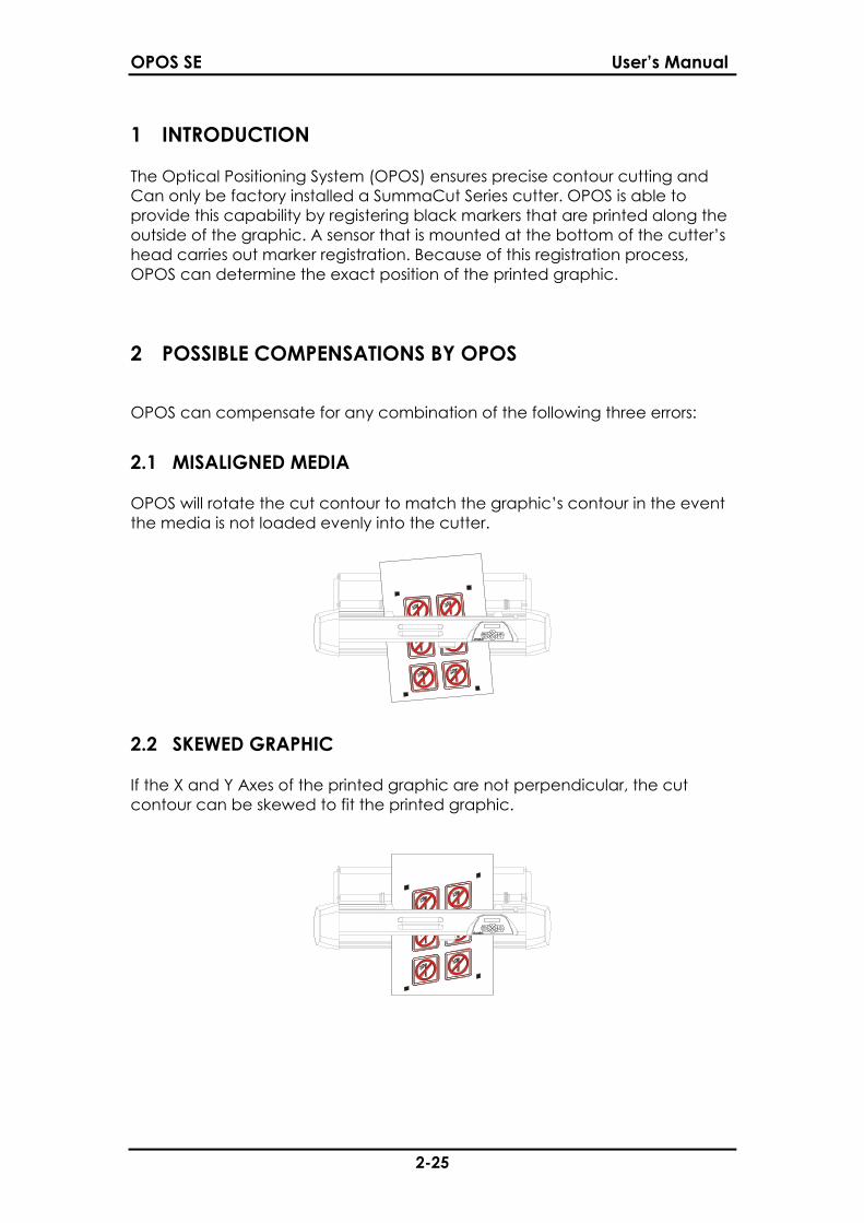
2.1 MISALIGNED MEDIA
OPOS will rotate the cut contour to match the graphic’s contour in the eventthe media is not loaded evenly into the cutter.
2.2 SKEWED GRAPHIC
If the X and Y Axes of the printed graphic are not perpendicular, the cutcontour can be skewed to fit the printed graphic.
OPOS SE User’s Manual
3-25
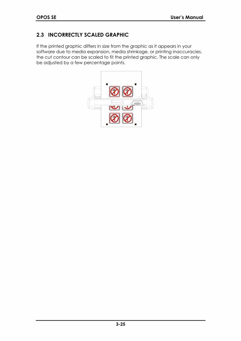
2.3 INCORRECTLY SCALED GRAPHIC
If the printed graphic differs in size from the graphic as it appears in yoursoftware due to media expansion, media shrinkage, or printing inaccuracies,the cut contour can be scaled to fit the printed graphic. The scale can onlybe adjusted by a few percentage points.
OPOS SE User’s Manual
4-25
3 CREATING A GRAPHIC
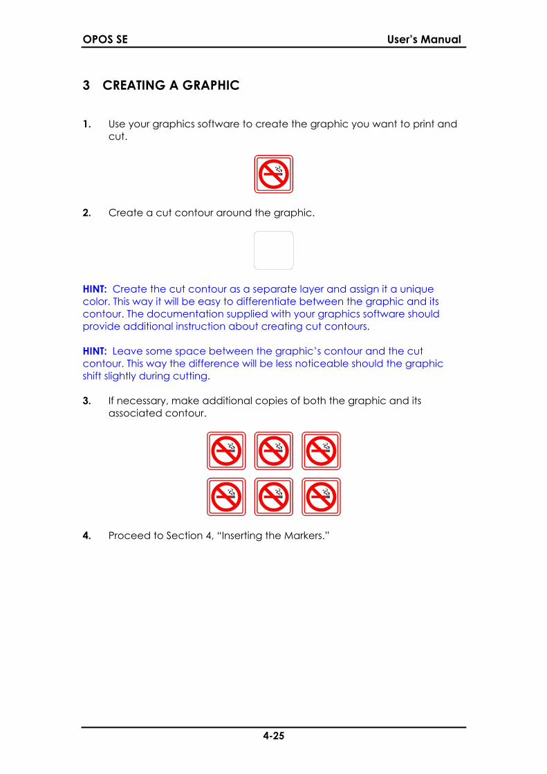
1. Use your graphics software to create the graphic you want to print andcut.
2. Create a cut contour around the graphic.
HINT: Create the cut contour as a separate layer and assign it a uniquecolor. This way it will be easy to differentiate between the graphic and itscontour. The documentation supplied with your graphics software shouldprovide additional instruction about creating cut contours.
HINT: Leave some space between the graphic’s contour and the cutcontour. This way the difference will be less noticeable should the graphicshift slightly during cutting.
3. If necessary, make additional copies of both the graphic and itsassociated contour.
4. Proceed to Section 4, “Inserting the Markers.”

OPOS SE User’s Manual
5-25
4 INSERTING THE MARKERS
1. Insert a marker to represent the Origin. The marker must be a blacksquare. Each of the marker’s four sides should measure 3mm but mustnot be less than 1.2mm or more than 10mm.
HINT: Create all the markers on a separate layer for easier handling.
NOTE: When printing on small media sheets, use smaller markers to minimizewaste of material.
2. Set the line style of the marker to None. Line styles of varying thicknessescan alter the size of the markers.
3. Make sure there is a white margin of about 3 - 4 times the marker sizearound the marker. If anything is printed within this margin, the sensormay be unable to locate the marker.
4. Make sure that the Origin marker is situated below and to the left of allcontours to be cut.
HINT: Manually place an identifying mark on the media to indicate whichmarker is the Origin. This will be helpful when the printed graphic needs to beloaded into the cutter.
5. Insert a horizontally aligned copie of the Origin marker at a knowninterval (X-Distance). Make sure there is enough white space aroundeach marker.
The X-Distance is the distance from the lower left corner of one marker to thelower left corner of the next marker and depends on several factors.Normally, 20cm is an appropriate distance. But, if the marker size is less than3x3mm, the X-Distance should be decreased. The X-Distance must be knownwhen setting the OPOS parameters.
X-Size
Y-Size
OriginMarker
WhiteSpace
OPOS SE User’s Manual
6-25
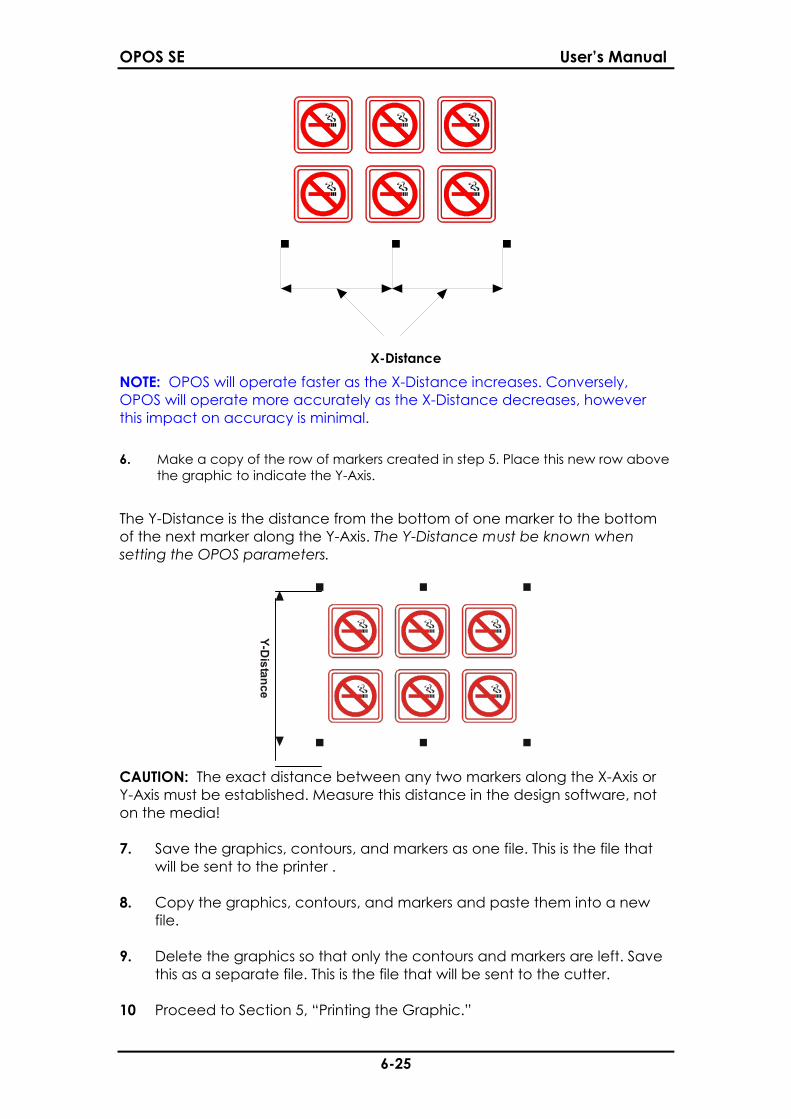
NOTE: OPOS will operate faster as the X-Distance increases. Conversely,OPOS will operate more accurately as the X-Distance decreases, howeverthis impact on accuracy is minimal.
6. Make a copy of the row of markers created in step 5. Place this new row abovethe graphic to indicate the Y-Axis.
The Y-Distance is the distance from the bottom of one marker to the bottomof the next marker along the Y-Axis. The Y-Distance must be known whensetting the OPOS parameters.
Y-Distance
CAUTION: The exact distance between any two markers along the X-Axis orY-Axis must be established. Measure this distance in the design software, noton the media!
7. Save the graphics, contours, and markers as one file. This is the file thatwill be sent to the printer .
8. Copy the graphics, contours, and markers and paste them into a newfile.
9. Delete the graphics so that only the contours and markers are left. Savethis as a separate file. This is the file that will be sent to the cutter.
10 Proceed to Section 5, “Printing the Graphic.”
X-Distance

OPOS SE User’s Manual
7-25
5 PRINTING THE GRAPHIC
1. Print the graphic and its markers with a printer (scale = 100%). Whenprinting on a roll, make sure that the graphic’s Origin marker coincideswith the media’s origin.
2. Make sure there is at least a 1cm (0.4in) between the marker and themedia border. A 2cm (0.8in) margin is preferable.
Min. 1cm
3. Leave a margin of at least 8cm (3.15in) following the print when usingsheets or when cutting the print off a roll.
4. Proceed to Section 6, “Loading the Cutter.”
Origin Marker
Min. 8cm
OPOS SE User’s Manual
8-25
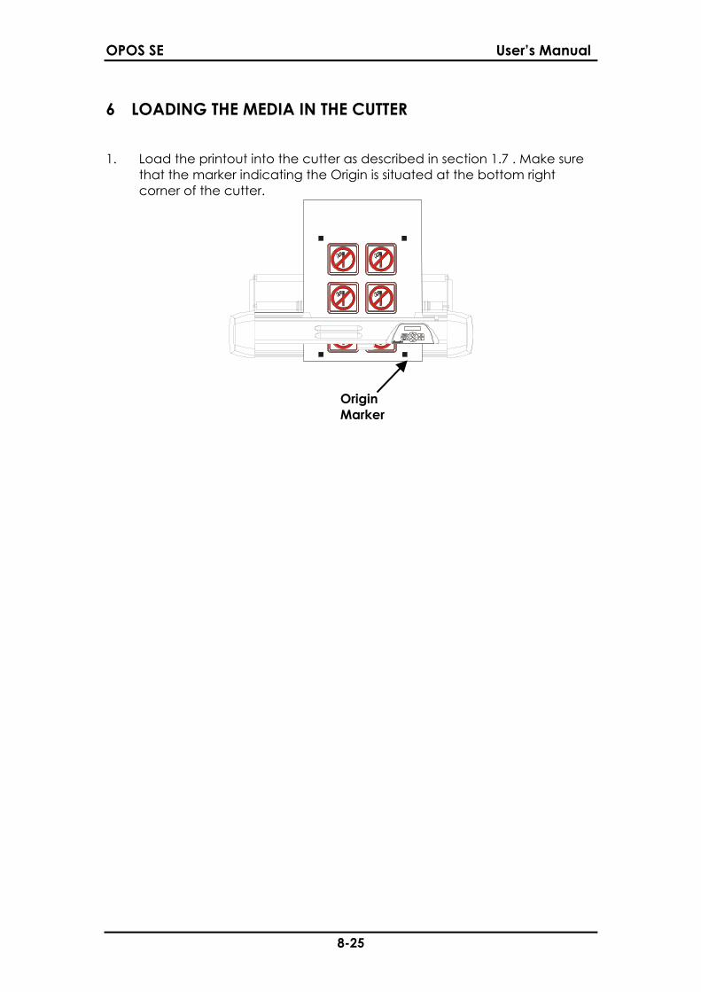
6 LOADING THE MEDIA IN THE CUTTER
1. Load the printout into the cutter as described in section 1.7 . Make surethat the marker indicating the Origin is situated at the bottom rightcorner of the cutter.
OriginMarker
OPOS SE User’s Manual
9-25
7 SETTING SPECIAL LOAD AND THE OPOS PARAMETERS
The Special Load setting determines whether the cutter uses OPOS, or one ofthe three manual alignment methods, for contour navigation.
The OPOS parameters are variables that define the distance, size, andnumber of markers.
The Special Load setting and the OPOS parameters can be set using eitherSumma Cutter Control or the cutter’s control panel.
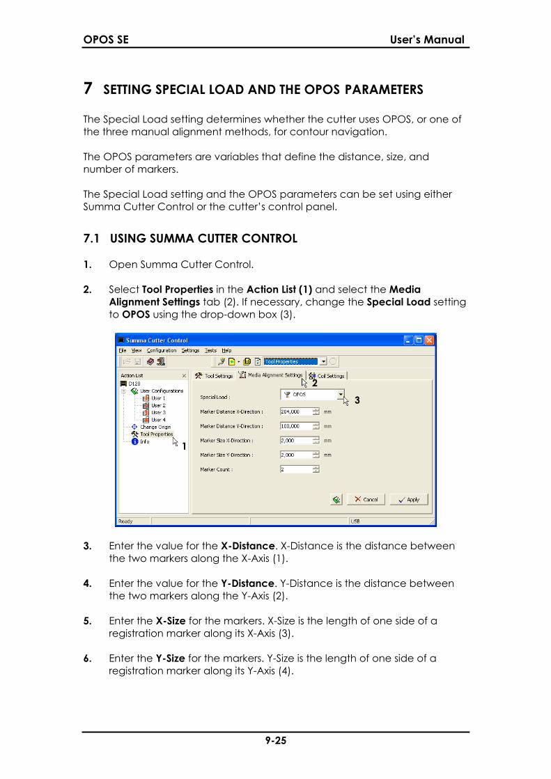
7.1 USING SUMMA CUTTER CONTROL
1. Open Summa Cutter Control.
2. Select Tool Properties in the Action List (1) and select the MediaAlignment Settings tab (2). If necessary, change the Special Load settingto OPOS using the drop-down box (3).
3. Enter the value for the X-Distance. X-Distance is the distance betweenthe two markers along the X-Axis (1).
4. Enter the value for the Y-Distance. Y-Distance is the distance betweenthe two markers along the Y-Axis (2).
5. Enter the X-Size for the markers. X-Size is the length of one side of aregistration marker along its X-Axis (3).
6. Enter the Y-Size for the markers. Y-Size is the length of one side of aregistration marker along its Y-Axis (4).
OPOS SE User’s Manual
10-25
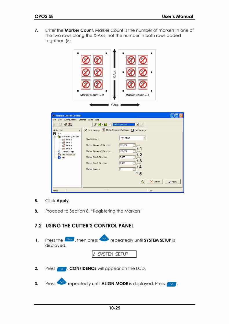
7. Enter the Marker Count. Marker Count is the number of markers in one ofthe two rows along the X-Axis, not the number in both rows addedtogether. (5)
Marker Count = 3Marker Count = 2
X-Ax
is
Y-Axis
8. Click Apply.
8. Proceed to Section 8, “Registering the Markers.”
7.2 USING THE CUTTER’S CONTROL PANEL
1. Press the , then press repeatedly until SYSTEM SETUP isdisplayed.
.. . .... . ..
2. Press . CONFIDENCE will appear on the LCD.
3. Press repeatedly until ALIGN MODE is displayed. Press .
OPOS SE User’s Manual
11-25
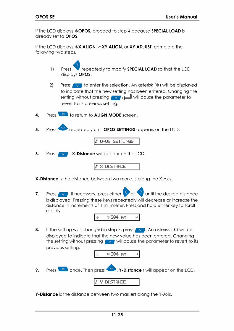
If the LCD displays OPOS, proceed to step 4 because SPECIAL LOAD isalready set to OPOS.
If the LCD displays X ALIGN, XY ALIGN, or XY ADJUST, complete thefollowing two steps.
1) Press repeatedly to modify SPECIAL LOAD so that the LCDdisplays OPOS.
2) Press to enter the selection. An asterisk ( ) will be displayedto indicate that the new setting has been entered. Changing thesetting without pressing will cause the parameter torevert to its previous setting.
4. Press to return to ALIGN MODE screen.
5. Press repeatedly until OPOS SETTINGS appears on the LCD.
.. . .... . ..
6. Press . X-Distance will appear on the LCD.
.. . .... . ..
X-Distance is the distance between two markers along the X-Axis.
7. Press . If necessary, press either or until the desired distanceis displayed. Pressing these keys repeatedly will decrease or increase thedistance in increments of 1 millimeter. Press and hold either key to scrollrapidly.
...... ..
8. If the setting was changed in step 7, press . An asterisk ( ) will bedisplayed to indicate that the new value has been entered. Changingthe setting without pressing will cause the parameter to revert to itsprevious setting.
...... ..
9. Press once. Then press . Y-Distance r will appear on the LCD.
.. . .... . ..
Y-Distance is the distance between two markers along the Y-Axis.
OPOS SE User’s Manual
12-25
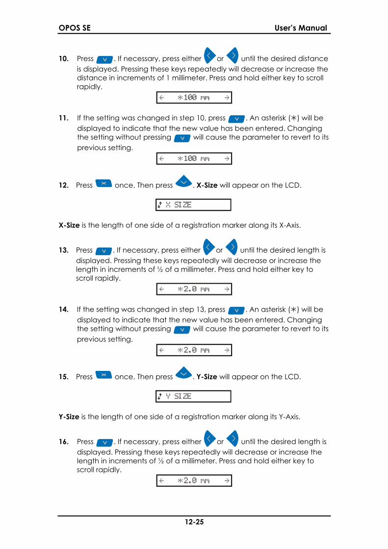
10. Press . If necessary, press either or until the desired distanceis displayed. Pressing these keys repeatedly will decrease or increase thedistance in increments of 1 millimeter. Press and hold either key to scrollrapidly.
...... ..
11. If the setting was changed in step 10, press . An asterisk ( ) will bedisplayed to indicate that the new value has been entered. Changingthe setting without pressing will cause the parameter to revert to itsprevious setting.
...... ..
12. Press once. Then press . X-Size will appear on the LCD.
.. . .... . ..
X-Size is the length of one side of a registration marker along its X-Axis.
13. Press . If necessary, press either or until the desired length isdisplayed. Pressing these keys repeatedly will decrease or increase thelength in increments of ½ of a millimeter. Press and hold either key toscroll rapidly.
...... ..
14. If the setting was changed in step 13, press . An asterisk ( ) will bedisplayed to indicate that the new value has been entered. Changingthe setting without pressing will cause the parameter to revert to itsprevious setting.
...... ..
15. Press once. Then press . Y-Size will appear on the LCD.
.. . .... . ..
Y-Size is the length of one side of a registration marker along its Y-Axis.
16. Press . If necessary, press either or until the desired length isdisplayed. Pressing these keys repeatedly will decrease or increase thelength in increments of ½ of a millimeter. Press and hold either key toscroll rapidly.
...... ..
OPOS SE User’s Manual
13-25
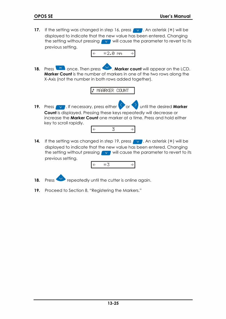
17. If the setting was changed in step 16, press . An asterisk ( ) will bedisplayed to indicate that the new value has been entered. Changingthe setting without pressing will cause the parameter to revert to itsprevious setting.
...... ..
18. Press once. Then press . Marker count will appear on the LCD.Marker Count is the number of markers in one of the two rows along theX-Axis (not the number in both rows added together).
.. . .... .
19. Press . If necessary, press either or until the desired MarkerCount is displayed. Pressing these keys repeatedly will decrease orincrease the Marker Count one marker at a time. Press and hold eitherkey to scroll rapidly.
........ ..
14. If the setting was changed in step 19, press . An asterisk ( ) will bedisplayed to indicate that the new value has been entered. Changingthe setting without pressing will cause the parameter to revert to itsprevious setting.
......
18. Press repeatedly until the cutter is online again.
19. Proceed to Section 8, “Registering the Markers.”
OPOS SE User’s Manual
14-25
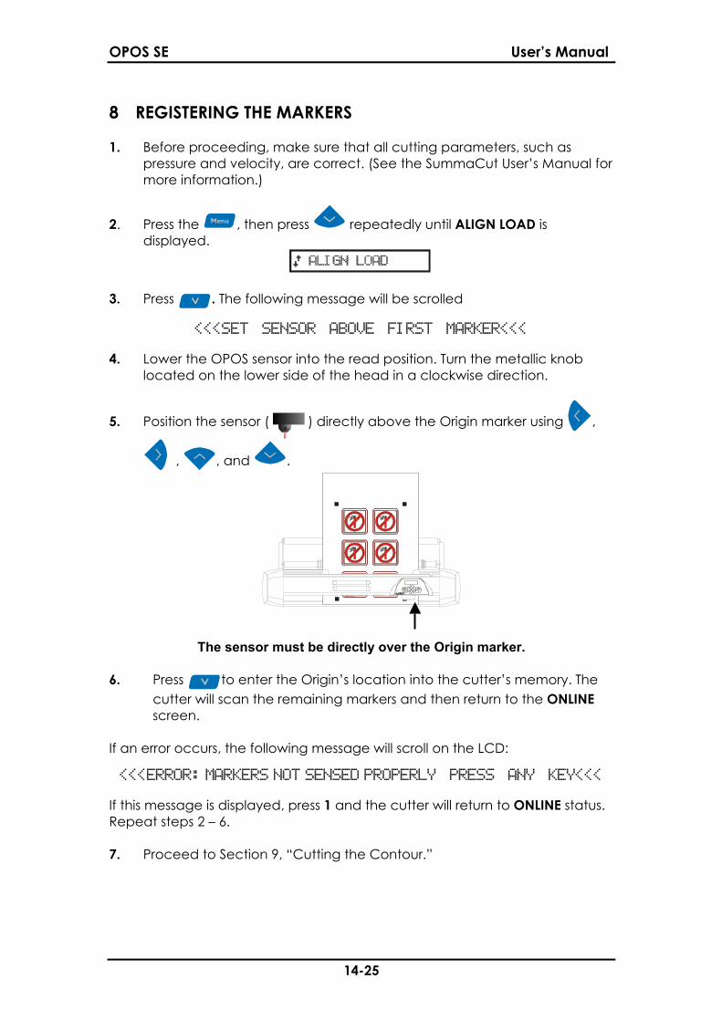
8 REGISTERING THE MARKERS 1. Before proceeding, make sure that all cutting parameters, such as
pressure and velocity, are correct. (See the SummaCut User’s Manual formore information.)
2. Press the , then press repeatedly until ALIGN LOAD isdisplayed.
.. . .... . ..
3. Press . The following message will be scrolled
<<<SET SENSOR ABOVE FIRST MARKER<<<
4. Lower the OPOS sensor into the read position. Turn the metallic knoblocated on the lower side of the head in a clockwise direction.
5. Position the sensor ( ) directly above the Origin marker using ,
, , and .
The sensor must be directly over the Origin marker.
6. Press to enter the Origin’s location into the cutter’s memory. Thecutter will scan the remaining markers and then return to the ONLINEscreen.
If an error occurs, the following message will scroll on the LCD:
<<<ERROR: MARKERS NOT SENSED PROPERLY PRESS ANY KEY<<<
If this message is displayed, press 1 and the cutter will return to ONLINE status.Repeat steps 2 – 6.
7. Proceed to Section 9, “Cutting the Contour.”
OPOS SE User’s Manual
15-25
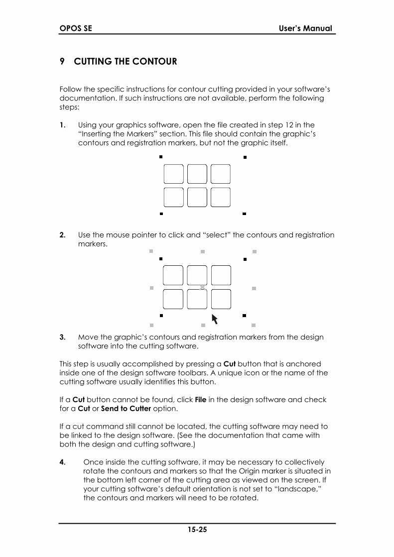
9 CUTTING THE CONTOUR
Follow the specific instructions for contour cutting provided in your software’sdocumentation. If such instructions are not available, perform the followingsteps:
1. Using your graphics software, open the file created in step 12 in the“Inserting the Markers” section. This file should contain the graphic’scontours and registration markers, but not the graphic itself.
2. Use the mouse pointer to click and “select” the contours and registrationmarkers.
3. Move the graphic’s contours and registration markers from the designsoftware into the cutting software.
This step is usually accomplished by pressing a Cut button that is anchoredinside one of the design software toolbars. A unique icon or the name of thecutting software usually identifies this button.
If a Cut button cannot be found, click File in the design software and checkfor a Cut or Send to Cutter option.
If a cut command still cannot be located, the cutting software may need tobe linked to the design software. (See the documentation that came withboth the design and cutting software.)
4. Once inside the cutting software, it may be necessary to collectivelyrotate the contours and markers so that the Origin marker is situated inthe bottom left corner of the cutting area as viewed on the screen. Ifyour cutting software’s default orientation is not set to “landscape,”the contours and markers will need to be rotated.

OPOS SE User’s Manual
16-25
Origin Marker Cutting Area
5. Use the mouse pointer to click and “select” the contours and registrationmarkers.
HINT: Some software will shift the selected contours to the Origin whencutting. This can be avoided by adding a small rectangular spacer that has itsbottom left corner in the Origin. Select this rectangle along with the contours.
6. Make sure that the cutter is connected to the computer and that thecutter is turned on. The cutter’s LCD should indicate that the cutter isONLINE.
7. Click Cut from within the cutting software. The cutter should begincutting the contour and return to ONLINE status when finished.
NOTE: Make sure that only the contours are cut.
OPOS SE User’s Manual
17-25
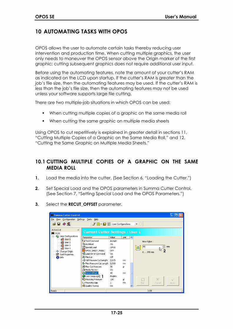
10 AUTOMATING TASKS WITH OPOS
OPOS allows the user to automate certain tasks thereby reducing userintervention and production time. When cutting multiple graphics, the useronly needs to maneuver the OPOS sensor above the Origin marker of the firstgraphic; cutting subsequent graphics does not require additional user input.
Before using the automating features, note the amount of your cutter’s RAMas indicated on the LCD upon startup. If the cutter’s RAM is greater than thejob’s file size, then the automating features may be used. If the cutter’s RAM isless than the job’s file size, then the automating features may not be usedunless your software supports large file cutting.
There are two multiple-job situations in which OPOS can be used:
When cutting multiple copies of a graphic on the same media roll
When cutting the same graphic on multiple media sheets
Using OPOS to cut repetitively is explained in greater detail in sections 11,“Cutting Multiple Copies of a Graphic on the Same Media Roll,” and 12,“Cutting the Same Graphic on Multiple Media Sheets.”
10.1 CUTTING MULTIPLE COPIES OF A GRAPHIC ON THE SAMEMEDIA ROLL
1. Load the media into the cutter. (See Section 6, “Loading the Cutter.”)
2. Set Special Load and the OPOS parameters in Summa Cutter Control.(See Section 7, “Setting Special Load and the OPOS Parameters.”)
3. Select the RECUT_OFFSET parameter.
OPOS SE User’s Manual
18-25
4. Set the RECUT_OFFSET parameter in the New Value window to equal thedistance between the last marker on the first graphic and the first markeron the next graphic. This setting reflects the distance between twographics.
5. Click Apply.
6. Register the markers. (See Section 8, “Registering the Markers.”)
7. Cut the first contour. (See Section 9, “Cutting the Contour.")
8. The cutter will stop after the first contour has been cut and the ONLINEscreen will be displayed.
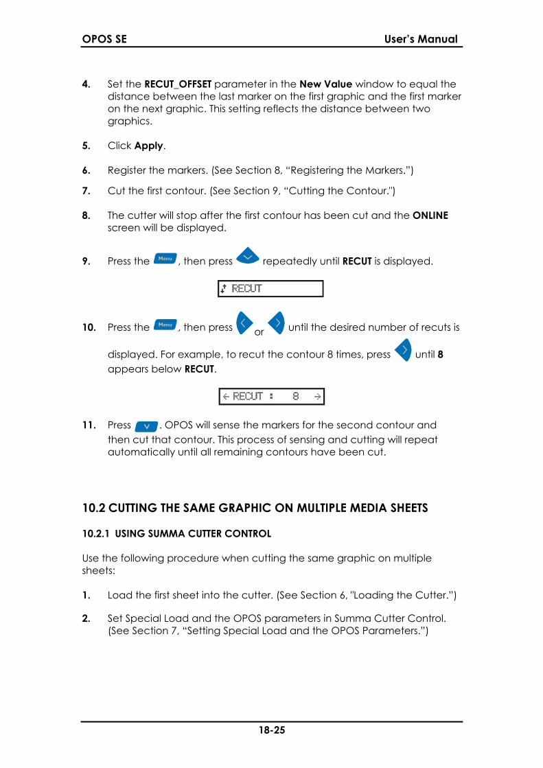
9. Press the , then press repeatedly until RECUT is displayed.
.. . .... ..
10. Press the , then press or until the desired number of recuts is
displayed. For example, to recut the contour 8 times, press until 8appears below RECUT.
.. . ... ..
11. Press . OPOS will sense the markers for the second contour andthen cut that contour. This process of sensing and cutting will repeatautomatically until all remaining contours have been cut.
10.2 CUTTING THE SAME GRAPHIC ON MULTIPLE MEDIA SHEETS
10.2.1 USING SUMMA CUTTER CONTROL
Use the following procedure when cutting the same graphic on multiplesheets:
1. Load the first sheet into the cutter. (See Section 6, "Loading the Cutter.”)
2. Set Special Load and the OPOS parameters in Summa Cutter Control.(See Section 7, “Setting Special Load and the OPOS Parameters.”)

OPOS SE User’s Manual
19-25
3. Select the OPOS_SHEET_MODE parameter. Set OPOS_SHEET_MODE to ONin the New Value window.
4. Click Apply.
5. Register the markers. (See Section 8, “Registering the Markers”.) Thecutter’s LCD will indicate that it is ready to cut the first sheet.
.. . ..
6. Cut the first contour. (See Section 9, “Cutting the Contour.”)
7. Raise the cam rollers and manually remove the sheet.
8. Insert the next sheet into the cutter. Situate the sheet in the same placeas the first sheet.
9. Lower the cam rollers while holding the sheet in place. OPOS will sensethe markers and cutting will resume. Repeat steps 7 - 9 until all sheetshave been cut.
10. To exit OPOS_SHEET_MODE, press the , then press repeatedlyuntil RECUT is displayed.
11. Press .
NOTE: If the cutter is turned off and then back on while OPOS_SHEET_MODE isset to ON, OPOS_SHEET_MODE will be set to OFF. This change will not bereflected in the OPOS_SHEET_MODE parameter in Summa Cutter Control.Therefore, Summa Cutter Control must be refreshed by clicking View and thenRefresh. The OPOS_SHEET_MODE parameter will be set to OFF. Sheet cuttingcan then be resumed by repeating steps 1 - 9.
OPOS SE User’s Manual
20-25
10.2.2 USING THE CUTTER’S CONTROL PANEL
Use the following procedure when cutting the same graphic on multiplesheets:
1. Load the first sheet into the cutter. (See Section 6, “Loading the Cutter.”)
2. Set Special Load and the OPOS parameters using the cutter’s controlpanel. (See Section 7, “Setting Special Load and the OPOSParameters.”)
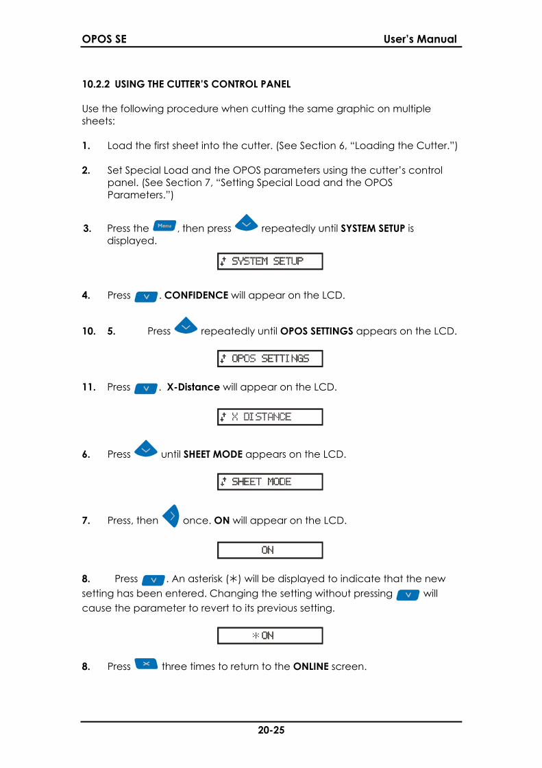
3. Press the , then press repeatedly until SYSTEM SETUP isdisplayed.
.. . .... . ..
4. Press . CONFIDENCE will appear on the LCD.
10. 5. Press repeatedly until OPOS SETTINGS appears on the LCD.
.. . .... . ..
11. Press . X-Distance will appear on the LCD.
.. . .... . ..
6. Press until SHEET MODE appears on the LCD.
.. . ..
7. Press, then once. ON will appear on the LCD.
.. . ..
8. Press . An asterisk ( ) will be displayed to indicate that the newsetting has been entered. Changing the setting without pressing willcause the parameter to revert to its previous setting.
.. . ..
8. Press three times to return to the ONLINE screen.

OPOS SE User’s Manual
21-25
9. Register the markers. (See Section 8, “Registering the Markers”.) Thecutter’s LCD will indicate that it is ready to cut the first sheet.
.. . ..
10. Cut the first contour. (See Section 9, “Cutting the Contour.”)
11. Raise the cam rollers and manually remove the sheet.
12. Insert the next sheet into the cutter. Situate the sheet in the same placeas the first sheet.
13. Lower the cam rollers while holding the sheet in place. OPOS will sensethe markers and cutting will resume. Repeat steps 7 - 9 until all sheetshave been cut.
14. To exit OPOS_SHEET_MODE, press the , then press repeatedlyuntil RECUT is displayed.
11. Press .
OPOS SE User’s Manual
22-25
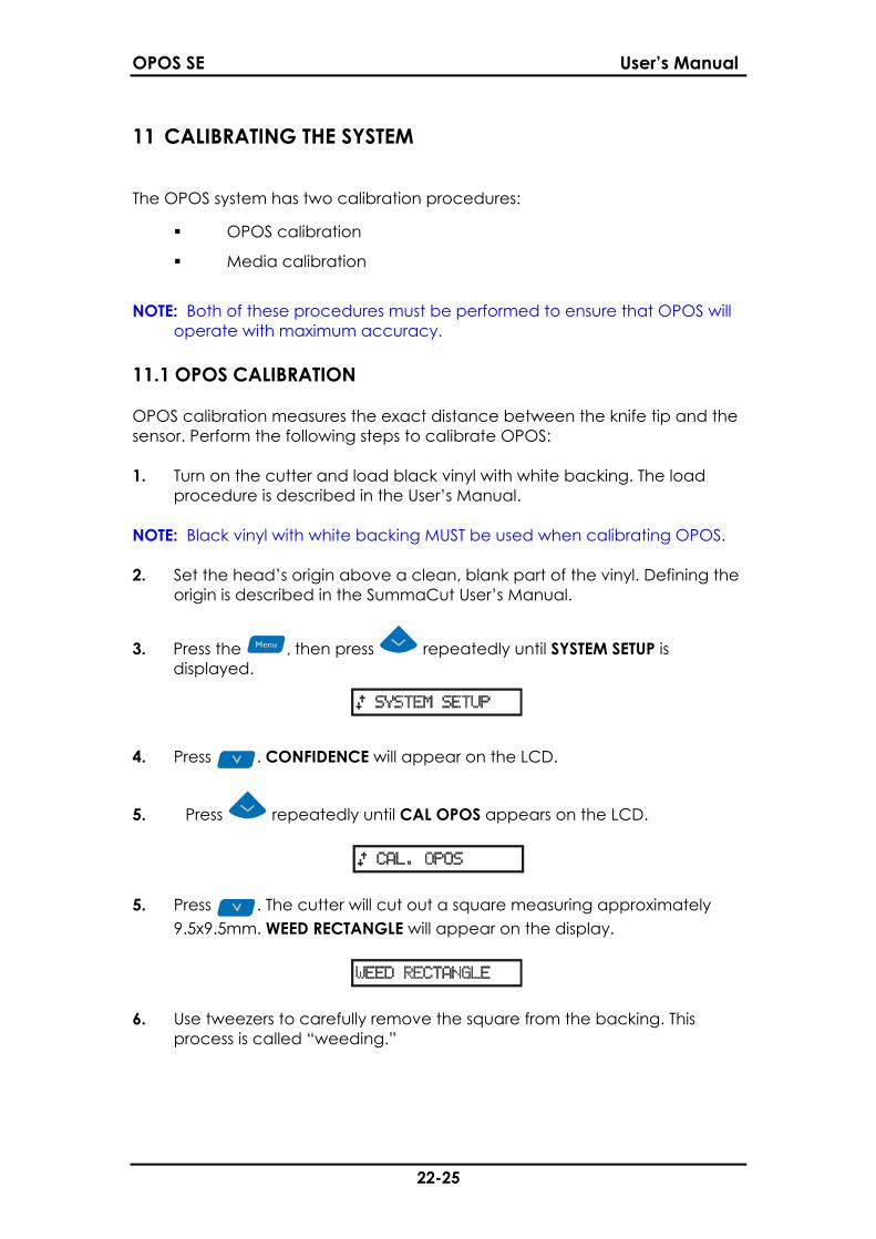
11 CALIBRATING THE SYSTEM
The OPOS system has two calibration procedures:
OPOS calibration
Media calibration
NOTE: Both of these procedures must be performed to ensure that OPOS willoperate with maximum accuracy.
11.1 OPOS CALIBRATION
OPOS calibration measures the exact distance between the knife tip and thesensor. Perform the following steps to calibrate OPOS:
1. Turn on the cutter and load black vinyl with white backing. The loadprocedure is described in the User’s Manual.
NOTE: Black vinyl with white backing MUST be used when calibrating OPOS.
2. Set the head’s origin above a clean, blank part of the vinyl. Defining theorigin is described in the SummaCut User’s Manual.
3. Press the , then press repeatedly until SYSTEM SETUP isdisplayed.
.. . .... . ..
4. Press . CONFIDENCE will appear on the LCD.
5. Press repeatedly until CAL OPOS appears on the LCD.
.. . .
5. Press . The cutter will cut out a square measuring approximately9.5x9.5mm. WEED RECTANGLE will appear on the display.
.. . ..
6. Use tweezers to carefully remove the square from the backing. Thisprocess is called “weeding.”
OPOS SE User’s Manual
23-25
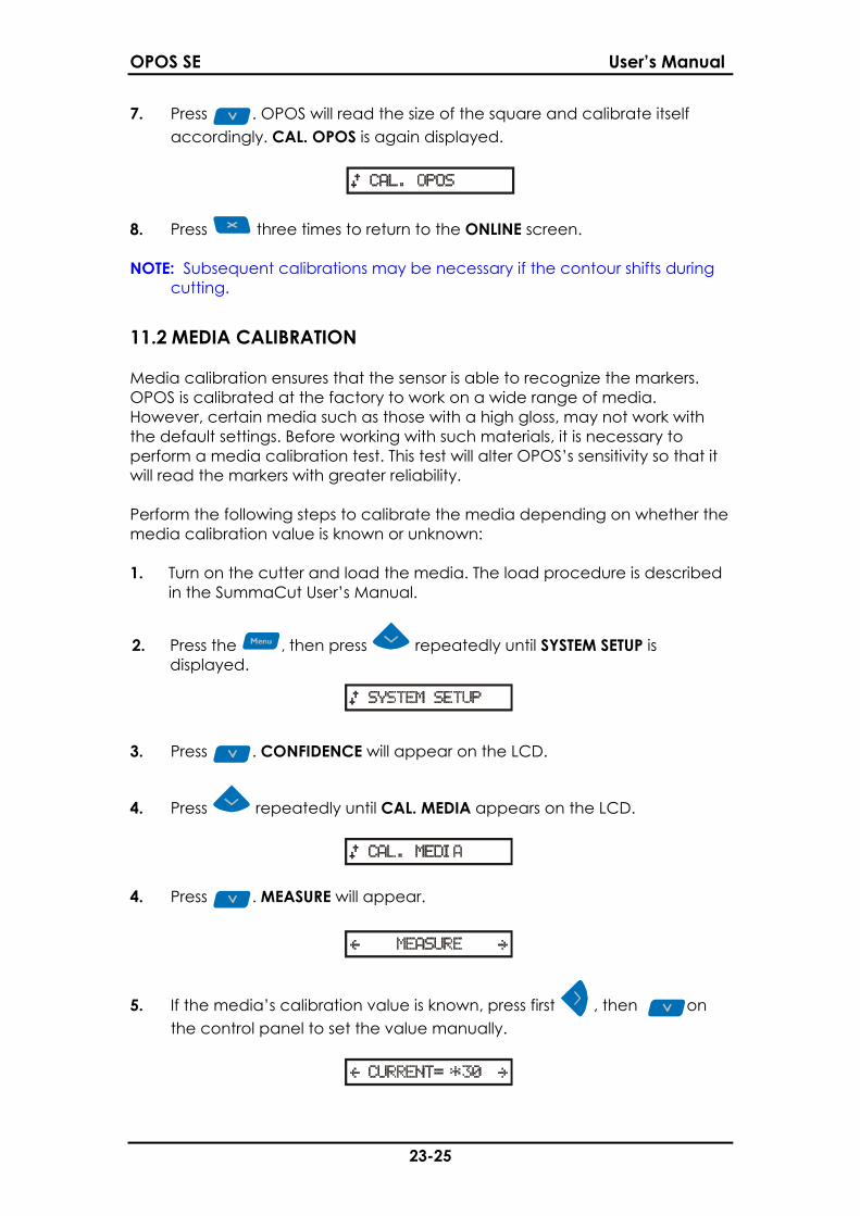
7. Press . OPOS will read the size of the square and calibrate itselfaccordingly. CAL. OPOS is again displayed.
.. . .
8. Press three times to return to the ONLINE screen.
NOTE: Subsequent calibrations may be necessary if the contour shifts duringcutting.
11.2 MEDIA CALIBRATION
Media calibration ensures that the sensor is able to recognize the markers.OPOS is calibrated at the factory to work on a wide range of media.However, certain media such as those with a high gloss, may not work withthe default settings. Before working with such materials, it is necessary toperform a media calibration test. This test will alter OPOS’s sensitivity so that itwill read the markers with greater reliability.
Perform the following steps to calibrate the media depending on whether themedia calibration value is known or unknown:
1. Turn on the cutter and load the media. The load procedure is describedin the SummaCut User’s Manual.
2. Press the , then press repeatedly until SYSTEM SETUP isdisplayed.
.. . .... . ..
3. Press . CONFIDENCE will appear on the LCD.
4. Press repeatedly until CAL. MEDIA appears on the LCD.
.. . .... .
4. Press . MEASURE will appear.
.. . ..
5. If the media’s calibration value is known, press first , then onthe control panel to set the value manually.
.. . ..
OPOS SE User’s Manual
24-25
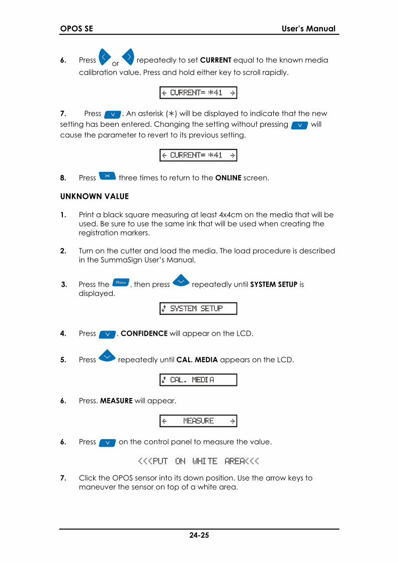
6. Press or repeatedly to set CURRENT equal to the known mediacalibration value. Press and hold either key to scroll rapidly.
.. . ..
7. Press . An asterisk ( ) will be displayed to indicate that the newsetting has been entered. Changing the setting without pressing willcause the parameter to revert to its previous setting.
.. . ..
8. Press three times to return to the ONLINE screen.
UNKNOWN VALUE
1. Print a black square measuring at least 4x4cm on the media that will beused. Be sure to use the same ink that will be used when creating theregistration markers.
2. Turn on the cutter and load the media. The load procedure is describedin the SummaSign User’s Manual.
3. Press the , then press repeatedly until SYSTEM SETUP isdisplayed.
.. . .... . ..
4. Press . CONFIDENCE will appear on the LCD.
5. Press repeatedly until CAL. MEDIA appears on the LCD.
.. . .... .
6. Press. MEASURE will appear.
.. . ..
6. Press on the control panel to measure the value.
<<<PUT ON WHITE AREA<<<
7. Click the OPOS sensor into its down position. Use the arrow keys tomaneuver the sensor on top of a white area.
OPOS SE User’s Manual
25-25
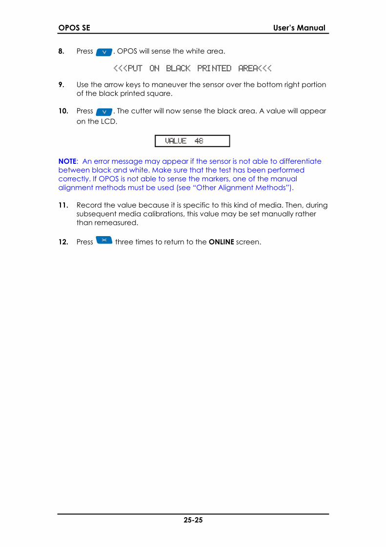
8. Press . OPOS will sense the white area.
<<<PUT ON BLACK PRINTED AREA<<<
9. Use the arrow keys to maneuver the sensor over the bottom right portionof the black printed square.
10. Press . The cutter will now sense the black area. A value will appearon the LCD.
.. . ..
NOTE: An error message may appear if the sensor is not able to differentiatebetween black and white. Make sure that the test has been performedcorrectly. If OPOS is not able to sense the markers, one of the manualalignment methods must be used (see “Other Alignment Methods”).
11. Record the value because it is specific to this kind of media. Then, duringsubsequent media calibrations, this value may be set manually ratherthan remeasured.
12. Press three times to return to the ONLINE screen.