dynamic study and stability analyze of damping cohefision and reactance in tcsc...
TRANSCRIPT
Dynamic study and Stability Analyze of Damping Cohefision and Reactance in TCSC Controller Connected on Optimization SMIB System
Farshad Mogharrab Tehrani Department of Electrical Engineering
Najafabad Branch, Islamic Azad University Isfahan, Iran
Abstract- Thyristor controlled series compensator (TCSC)
controller, can control the line impedance through the introdu
ction of a thyristor-controlled capacitor in series with the
transmission line. The TCSC controller is useful for stability
improvement. Model is different from other paper because
synchronous generator with just field circuit and one damper on q axis is used. While in other studies Phillips-Heffron has
been uses .At the first step, the transition from a capacitive
mode to bypass mode the TCSC controller is modelled with
detailed dynamics. The TCSC controller is modelled in
stability improvement. Then simulated TCSC shows that the
oscillations are changed with escalate the damping coefficient.
Change in value of reactance of the TCSC also affects the
stability of the system. The analysis shows that if compensation
is provided through TCSC controller then the system attains
stability at a faster rate that has come in another paper from
these writers.
Keywords- Power System Stability; Transient Stability Limit; FACTS; Voltage Stability.
I. INTRODUCTION
F ACTs controllers can balance the power flow and thereby using the existing power system network most efficiently. By fast response of FACTs controllers, facts can improve the stability of electrical power systems by helping critically disturbed generators to give away the excess energy got through the acceleration during fault. TCSC is an important device in FACTS family and is widely used as an effective and economical means to solve the power system stability problem. TCSC is an effective and economical means of solving problems of transient stability in long transmission lines. By flexibly quickly and adjusting the reactance of the TCSC, many relevant benefits can be achieved such as the better utilization of transmission capability, efficient power flow control, and transient stability improvement, power oscillation damping, control over sub synchronous resonance (SSR), and fault current limitation. In new past decades, one of the problems that got wide attention is the power system instabilities. With the lack of new generation and transmission facilities and over exploitation of the existing facilities geared by escalate in load demand make these kinds of problems more imminent in modem power systems. The problem of transient stability after a major fault can become a transmission power limiting factor. The power system
978-1-61284-486-2/111$26.00 ©2011 IEEE
270
Ghazanfar Shahgholian, Hossein Pourghassem Department of Electrical Engineering
Najafabad Branch, Islamic Azad University Isfahan, Iran
[email protected], h [email protected]
should adjust to system conditions, In other words, power system should be flexible.
II. FACTS CONTROLLER IN POWER SY STEM
A lot of studies and reports have been published on theses subjects. These Books cover the basic idea about the F ACTs devices. A detailed explanation has been given for all the FACTs devices. FACTs technology clears new opportunities for controlling and enhancing the useable capacity of present, as well as new upgraded lines. The possibility that current through a line can be controlled at a reasonable cost enables a large potential of escalating the capacity of existing lines with longer conductors and use one of the FACTs controller to enable corresponding power to flow through such lines under normal and contingency conditions. These opportunities goes up through the capability of FACTs controllers to control the interrelated parameters that conducts the operation of transmission system including shunt impedance, series impedance, voltage, current, phase angle and the damping of oscillations at various frequencies below the rated frequency. By providing added flexibility , FACTs controllers can enable a line to get power closer to its thermal rating. FACTs technology points to devices that enable flexible electrical power system operation, i.e. controlled active & reactive Power flow redirection in transmission paths. Using power electronics with tum off capability cause F ACTs device offers continuous control of power flow or voltage, against daily load changes or change in network topologies. The second generation FACTs results with much smaller reactive elements by. Because of their fast response FACTs can also improve the stability of an electrical power system by helping critically disturbed generators to give away the extra energy got through the acceleration during fault. A TCSC is a series controlled capacitive reactance that can provide continuous control of power on the AC line over a spread range. A simple understanding of TCSC functioning can be obtained by analyzing the behavior of a variable inductor connected in series with a fixed capacitor, as shown in figure 1. The equivalent impedance Zeq of this LC combination can be expressed as:
(I)

If LCol> I, the reactance of the FC is less than that of the parallel connected variable reactor and this combination provides a variable capacitive reactance. If Loi=l, a resonance develops that result in infinite capacitive impedance, this is an unacceptable condition. If LCol<l, then the combination provides inductance above the value of fixed inductor. This situation corresponds to the inductive venire mode of the TCSC operation, discussed in further section.
C +1-
Figure 1. A variable inductor connected in shunt with a fixed capacitor.
The behavior of TCSC is same to that of the LC parallel combination. The difference is that the LC combination analysis is based on pure sinusoidal voltage and current in the circuit· where as in TCSC because of the voltage and current in'the FC and thyristor controlled reactor (TCR) is not sinusoidal because of thyristor switching. The detail of TCSC working is discussed in further sections. TCSC circuit for the analysis can be shown in figure 2.
Vc{t) �I • .
i�(t) Figure 2. Simplified TCSC circuit.
The steady state thyristor current h can be given as
where
K2 cos 13 iT(t) =--- Im (cos 0Jt - -- cosOJrt) (2) K2 - 2 coskj3
-I3�OJt�I3
(3)
k=: =J;: (4)
The steady state capacitor voltage at the instant OJt = -13 is given as:
V I (t) = I mX e (sin j3t -k cos j3tankj3) (5) e K2_1 At OJ, = 13, iT = 0 capacitor voltage is
ve(t) = ve2 = -vel (6) The final expression for the capacitor voltage is given as
I m X e . k cos 13 . ) V (t)=--(-Slllwt+ --SlllOJrt e K2 -1 coskj3 -13 � OJt � 13 (7)
271
v c (t) = vC2 + Tm Xc (sin OJt - sin 13) 13 � OJt � 1[- 13 (8)
The fundamental component, V CF , is obtained as:
VCF = jj,j {�{ vc(t)sinOJtd(OJt) (9)
The equivalent TCSC reactance is given by:
VCF X� 213+ sin 213 XTCSC =-= Xc ( ) +
1m Xc -Xp 1[ (1 0)
4X� cos 2 j3(Ktan kj3 -tan Kj3) (Xc-Xp)(K2_1�
where V CF is fundamental component of the capacitor voltage, Xc is nominal reactance of the fixed capacitor only, Xp is inductive reactance of inductor connected in parallel with fixed capacitor. The resonant zone is avoided by installing limits on the firing angle. TCSC is mainly used in capacitive zone. The complete system has been represented in terms of SIMULINK blocks in a single integral model. SIMULINK is a software tool associated with MATLAB, used for modeling, simulating and analyzing dynamical systems. Single Machine Infinite Bus (SMIB ) system with all the required components is modeled and is described. Simulink model of SMIB system with TCSC has been illustrated in Figure 3.
'''] eo - I� '� J "'"
Scope 12
---�L+=i
Figure3. Model of SMIB system using TCSC
III. SIMULATION RESULTS
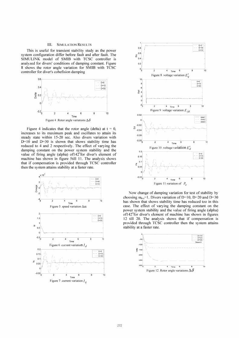
This is useful for transient stability study as the power system configuration differ before fault and after fault. The SIMULINK model of SMIB with TCSC controller is analyzed for divers' conditions of damping constant. Figure 8 shows the rotor angle variation for SMIB with TCSC controller for diver's cohefision damping
0.6-----------------
- 0=0 - - 0=10 OA- 0=30 -
� 0.2 o
-0.2 o 10
Time Figure 4 .Rotor angle variations!J.(j
Figure 4 indicates that the rotor angle (delta) at t = 0, increases to its maximum peak and oscillates to attain its steady state within 15-20 sec. Also divers variation with 0=10 and 0=30 is shown that shows stability time has reduced to 4 and 2 respectively. The effect of varying the damping constant on the power system stability and the value of firing angle (alpha) ofl42ofor diver's element of machine has shown in figure 5till I I. The analysis shows that if compensation is provided through TCSC controller then the system attains stability at a faster rate.
:Q
ro �
E o -2-
I D=O I D=30 - - D=10
40�--�--�--�--�---71C· Time
Figure 5 .speed variation!J.QJ
0=0 1.5- - - 0=10-
-0=30 1-
0.5-
0-
-0.5 0 1C
Time Figure 6 .current variation / d
0.2 D=O D=10 -
-D=30
-0.050c---�-c---�--�---=-----c1C Time
Figure 7 .current variation / q
272
� w
0.8
0.6 0-
w
0.4
0.2
00 4 Time 6 10
Figure 8 .voltage variation E� 10
- 0=0
I 0=10 -0=30
� 34 I
o \ -20:---=-----';-4-T-;m-e ----;O6------O;---�,0
0.02
-0.02
-0.04
-0.06-
Figure 9 . voltage variation Efd data1
- - data2_ data3
4 Time 1C
Figure 10 . voltage variation Ed - 0=0 - - 0=10 -0=30
4 Time 10
Figure I I. variation of Pe
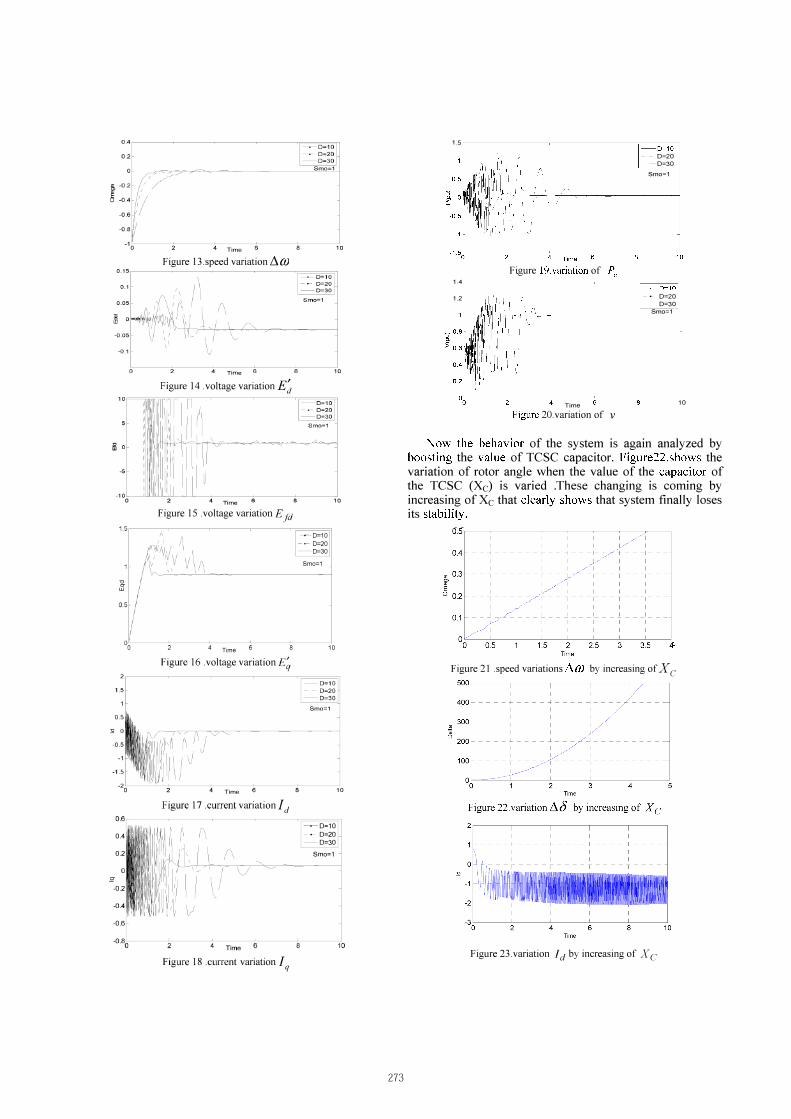
Now change of damping variation for test of stability by choosing COmo=1. Oivers variation of 0=1 0, 0=20 and 0=30 has shown that shows stability time has reduced too in this case. The effect of varying the damping constant on the power system stability and the value of firing angle (alpha) ofl42°for diver's element of machine has shown in figures 12 till 20. The analysis shows that if compensation is provided through TCSC controller then the system attains stability at a faster rate.
-50 -100
� -150 -200
-3000:---cO-----c4-T-im-e��--�-�10 Figure 12 .Rotor angle variations /),,0
0.4 ---�-----------_--=-� . �:;� 1-0.2-
5-
� 0-
-5
-10-o
4 Time Figure 13. speed variation � m
Time Figure 14 . voltage variation E�
Time Figure 15 .voltage variation Erd
D=3� - Smo=1
10
10
10
1.5-------�---�---_===
u rr
w
0.5-
Time
----.-0=10 - 0- 0=20
0=30
Smo=1
10
1.5 1-0=10
- - 0=20 -0=30
Smo=1
-1.50----O----c--
T-;
1.4
1.2
Figure 19.variation of Pc
'1"'1" ' 1!:i:IIIIII:;:', "I" 'I ,,1,11 ' 1 1 1 ' ,
, 'I, II
,11.1 .. '1 " ,
I' , i'
Time
Figure 20.variation of v
'1�0=10 - 0- 0=20
0=30 Smo=1
10
Now the behavior of the system is again analyzed by boosting the value of TCSC capacitor. Figure22.shows the variation of rotor angle when the value of the capacitor of the TCSC (Xc) is varied .These changing is coming by increasing of Xc that clearly shows that system finally loses its stability.
0.5
04
m 0.3 � E o 0.2 - - - - - - - - -
0.1
0.5 1 .5 2.5 Time
3 3.5 4
Figure 16 .voltage variation Eq' A X Figure 21 .speed variations tim by increasing of c
Smo=1
Time 1 0
Figure 17 .current variation I" 0.6-------�---�--------
0.4
0.2
-0.2
-0.6
. 0=10 - � 0=20 -0=30
Smo=1 -
-0.80-------�--
T-; m
-
e
--=-------�
10
Figure 18 .current variation 1'1 Figure 23.variation I d by increasing of Xc
273
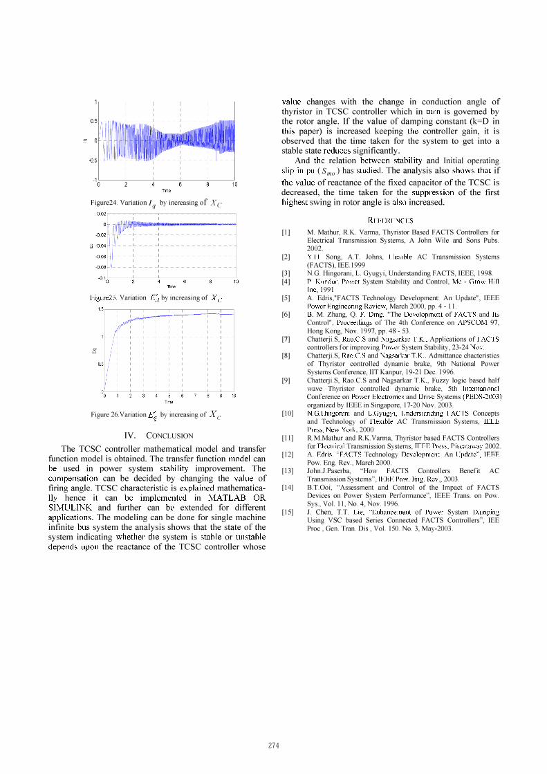
Figure24. Variation I q by increasing of Xc
Figure25. Variation Ed by increasing of Xc:
Figure 26.Variation E� by increasing of Xc
IV. CONCLUSION
The TCSC controller mathematical model and transfer function model is obtained. The transfer function model can be used in power system stability improvement. The compensation can be decided by changing the value of firing angle. TCSC characteristic is explained mathematically hence it can be implemented in MA TLAB OR
SIMULINK and further can be extended for different applications. The modeling can be done for single machine infinite bus system the analysis shows that the state of the system indicating whether the system is stable or unstable depends upon the reactance of the TCSC controller whose
274
value changes with the change in conduction angle of thyristor in TCSC controller which in turn is governed by the rotor angle. If the value of damping constant (k=D in this paper) is increased keeping the controller gain, it is observed that the time taken for the system to get into a stable state reduces significantly.
And the relation between stability and Initial operating slip in pu (Smo) has studied. The analysis also shows that if
the value of reactance of the fixed capacitor of the TCSC is decreased, the time taken for the suppression of the first highest swing in rotor angle is also increased.
REFERENCES
[I] M. Mathur, RK. Varma, Thyristor Based FACTS Controllers for Electrical Transmission Systems, A John Wile and Sons Pubs. 2002.
[2]
[3] [4]
[5]
[6]
[7]
[8]
[9]
[10]
[ 11]
[12]
[13]
[14]
[IS]
Y.H. Song, AT Johns, Flexible AC Transmission Systems (FACTS), IEEI999 N.G. Hingorani, L. Gyugyi, Understanding FACTS, IEEE, 1998. P. Kundur, Power System Stability and Control, Mc - Grow Hill Inc, 1991 A Edris,"FACTS Technology Development An Update", IEEE Power Engineering Review, March 2000, pp. 4 - II. B. M Zhang, Q. F. Ding, "The Development of FACTS and Its Control", Proceedings of The 4th Conference on APSCOM 97, Hong Kong, Nov. 1997, pp. 48 - 53. Chatterji.S, Rao.CS and Nagsarkar TK., Applications of FACTS controllers for improving Power System Stability, 23-24 Nov. Chatterji.S, Rao.CS and Nagsarkar TK., Admittance chacteristics of Thyristor controlled dynamic brake, 9th National Power Systems Conference, llT Kanpur, 19-21 Dec. 1996. Chattezii.S, Rao.CS and Nagsarkar TK , Fuzzy logic based half wave Thyristor controlled dynamic brake, 5th International Conference on Power Electronics and Drive Systems (PEDS-2003) organized by IEEE in Singapore, 17-20 Nov. 2003. N.G.Hingorani and L.Gyugyi, Understanding FACTS Concepts and Technology of Flexible AC Transmission Systems, IEEE Press, New York, 2000 RM.Mathur and RK.Varma, Thyristor based FACTS Controllers for Electrical Transmission Systems, IEEE Press, Piscataway 2002. A Edris, "FACTS Technology Development An Update", IEEE Pow Eng. Rev , March 2000. John.lPaserba, "How FACTS Controllers Benefit AC Transmission Systems", IEEE Pow Eng. Rev., 2003. BTOoi, "Assessment and Control of the Impact of FACTS Devices on Power System Performance", IEEE Trans. on Pow. Sys., Vol. 11, No. 4, Nov. 1996. J Chen, TT Lie, "Enhancement of Power System Damping Using VSC based Series Connected FACTS Controllers", IEE Proc , Gen. Tran. Dis , Vol. 150. No. 3, May-2003.