e200p operation manual - kuna impex operation manual contents preface 1 chapter 1 product...
TRANSCRIPT

E200P Operation Manual
(Version: V1.01)

E200P Operation Manual
Contents
Preface ......................................................................................................... 1 Chapter 1 Product Introduction .............................................................................. 3
1.1 Characteristic ................................................................................................. 3 1.2 Operation Panel ............................................................................................. 3 1.3 Display ........................................................................................................... 4
Chapter 2 Operation Example ................................................................................. 6 2.1 Single-Step .................................................................................................... 6
2.1.1 Background ........................................................................................................ 6 2.1.2 Analysis ............................................................................................................. 6 2.1.3 Procedure .......................................................................................................... 6
2.2 Mutil-Step ....................................................................................................... 7 2.2.1 Background ........................................................................................................ 7 2.2.2 Analysis ............................................................................................................. 7 2.2.3 Procedure .......................................................................................................... 8
Chapter 3 Operation Description .......................................................................... 10 3.1 Tipwizard ..................................................................................................... 10
3.1.1 Start and Stop .................................................................................................. 10 3.1.2 Parameter Setting ............................................................................................ 10 3.1.3 Alarm Reset ..................................................................................................... 10 3.1.4 Monitor ............................................................................................................. 10
3.2 Operation Flow ............................................................................................. 11 3.3 Single-Step .................................................................................................. 11 3.4 Multi-Step ..................................................................................................... 13 3.5 Manual ......................................................................................................... 16 3.6 Alarm and Monitor ........................................................................................ 17
Appendix A Common fault and troubleshooting............................................... 19 Appendix B Alarm List ........................................................................................ 20
Appendix C Parameter Description ....................................................... 21

E200P Operation Manual
1
Preface
Synopsis
This document guides the operator how to operate the E200P press break
numerical control device.
Chapter 1 describes panel and page.
Chapter 2 describes the example operation of the Single-Step and Mutil-Step.
Chapter 3 describes the operation guide of the pages.
Intended Audience
This document is intended for the authorized and properly trained persons:
Device manufacturer: In the device production process, the people who diagnose
the device have the highest managing privileges.
System integrators: usually refers to the technical personnel of machine tool
manufacturers, who can configure the machine parameters to commissioning the
system.
Operator: use the machine to do the programming work, set the programming
constant parameters.
Attention
Copy right is preserved by ESTUN. Do not add or delete part or all of the manual
content without ESTUN’s consent. Do not use part or all of manual content for the
third party’s design.
E200P device provides complete software control and has no mechanical
protection device for operator or the tool machine. Therefore, in case of malfunction,
machine tool must provide protection device for operator and external part of the
machine tool. ESTUN is not responsible for any direct or indirect losses caused by
normal or abnormal operation of the device.
ESTUN preserves the right to modifying this manual in the event of function adding
or print error.
E200P device has the light protection function, but only works on the CLOSED
stage, it is unavailable on others stage.

E200P Operation Manual
2
Caution Sign
The following symbols with an adjoining safety advice or notice are used in this
document. You have to read the safety advices carefully and adhere them strictly!
Risk of injury!
If you do not adhere the safety advise adjoining this symbol, there is
danger to life and health of individuals!
Hazard to individuals!
If you do not adhere the safety advice adjoining this symbol, there is
obvious hazard to individuals!
Note or pointer.
This symbol indicates information that contributes to better understanding.
E200P Operation Manual
3
Chapter 1 Product Introduction
1.1 Characteristic
E200P CNC device is a very suitable for torsional axis bending machine, providing solutions
for most of the machine both complete and economy, with high performance, flexible
configuration, compact structure, easy to use, high reliability characteristic:
Servo control, can realize the backgauge and high accuracy of control block.
Unilateral and bilateral location, to improve the positioning precision and reduce
screw clearance.
The main action of the machine can be configured, such as fast closing, pressing,
decompression, opening.
Backgauge can automatic homing.
Backgauge can be adjusted through the manual keys.
All ports can be configured directly on the device page, and the device has
self-checking function.
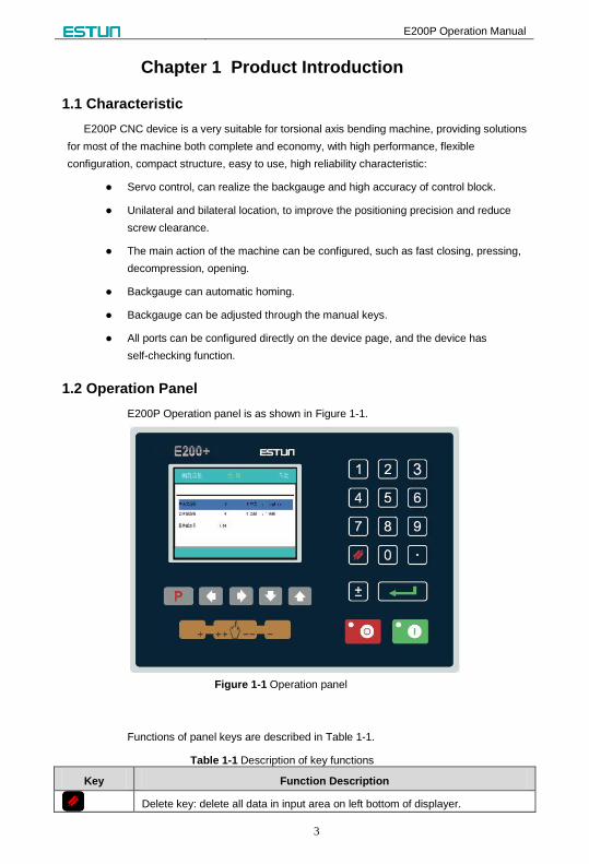
1.2 Operation Panel
E200P Operation panel is as shown in Figure 1-1.
Figure 1-1 Operation panel
Functions of panel keys are described in Table 1-1.
Table 1-1 Description of key functions
Key Function Description
Delete key: delete all data in input area on left bottom of displayer.

E200P Operation Manual
4
Key Function Description
Enter key: confirm the input content. If no content is input, the key has the similar
function to direction key .
Start key: automatic start-up, top left corner of the key is operation indicator
LED. When operation is started, this indicator LED is on.
Stop key: stop operation, top left corner of the key is Stop indicator LED. When
initialize normal start-up and no operation, this indicator LED is on.
Left direction key: page forward, cursor remove
Right direction key: page backward, cursor remove
Up direction key: select parameter upward
Down direction key: select parameter downward
Function switch: switch over different function pages
Symbolic key: user input symbol, or start diagnosis.
~ Numeric key: when setting parameter, input value.
Decimal point key: when set up parameter, input decimal point.
Manual movement key: in case of manual adjustment, make adjustment object
move in forward direction at low speed.
Manual movement key: in case of manual adjustment, make adjustment object
move in backward direction at low speed.
High speed selection key: in case of manual adjustment, press this key and
press simultaneously, make adjustment object move in increasing
direction at high speed, then press , make adjustment object move in
decreasing direction at high speed.
1.3 Display
SINGLE
: DestPosX Unit: mm
X= 100.50 Y = 120.05
XP = 100.50 YP = 300.00
DX = 20.00 HT = 2.00
DLY= 2.00 PP = 150
CP = 100 OPN= 0.00
XP = 120.00
Page name
Interpretation
and Unit
Parameter
editing area
Current Position
Figure 1-2 Display area
Page name: here shows the name of the current page.

E200P Operation Manual
5
Current Position: here shows the relative position of the X-axis and Y-axis.
Parameter editing area: here shows the editable parameters.
Interpretation and Unit: here shows interpretation and unit of parameters the cursor
on.
E200P Operation Manual
6
Chapter 2 Operation Example
2.1 Single-Step
2.1.1 Background
Now, There are a number of material, needs to be processed into workpiece, the
require as following:
Depth of bending is 100.00mm
Position of the backgauge is 80.00mm
Distance of retracting is 5.00mm
Time for the backgauge retract waiting is 2.00s
Time for the block holds the pressure is3.00s
Workpiece is 10.
2.1.2 Analysis
Parameter Setting
XP 80.00mm
YP 100.00mm
DX 5.00mm
HT 3.00s
DLY 2.00s
PP 10
Others According to the actual situation to set.
2.1.3 Procedure
Step 1 When the E200P device is electrified, wait a few seconds into the SINGLE page
(Default page).
Step 2 According to the analysis, press the arrow keys and number keys to modify the
corresponding parameters, as shown in Figure 2-1.
E200P Operation Manual
7
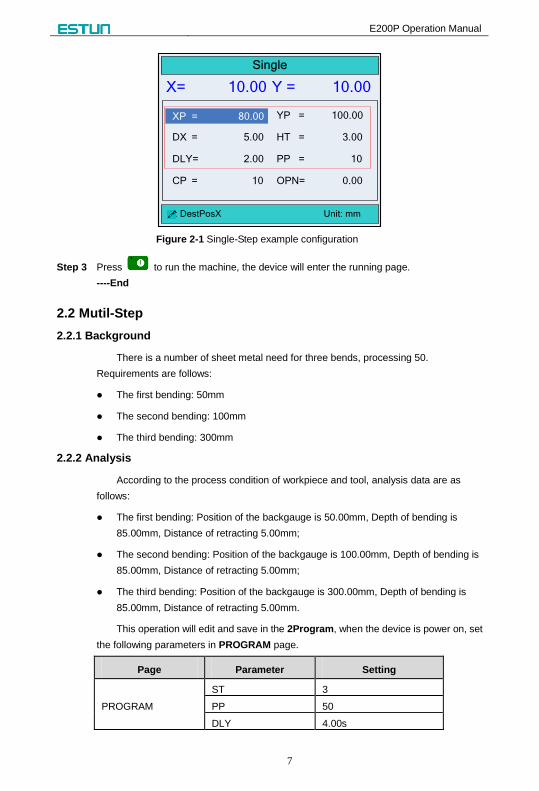
Single
: DestPosX Unit: mm
X= 10.00 Y = 10.00
XP = 80.00 YP = 100.00
DX = 5.00 HT = 3.00
DLY= 2.00 PP = 10
CP = 10 OPN= 0.00
XP = 80.00
Figure 2-1 Single-Step example configuration
Step 3 Press to run the machine, the device will enter the running page.
----End
2.2 Mutil-Step
2.2.1 Background
There is a number of sheet metal need for three bends, processing 50.
Requirements are follows:
The first bending: 50mm
The second bending: 100mm
The third bending: 300mm
2.2.2 Analysis
According to the process condition of workpiece and tool, analysis data are as
follows:
The first bending: Position of the backgauge is 50.00mm, Depth of bending is
85.00mm, Distance of retracting 5.00mm;
The second bending: Position of the backgauge is 100.00mm, Depth of bending is
85.00mm, Distance of retracting 5.00mm;
The third bending: Position of the backgauge is 300.00mm, Depth of bending is
85.00mm, Distance of retracting 5.00mm.
This operation will edit and save in the 2Program, when the device is power on, set
the following parameters in PROGRAM page.
Page Parameter Setting
PROGRAM
ST 3
PP 50
DLY 4.00s

E200P Operation Manual
8
Page Parameter Setting
HT 2.00s
ST 1/3
XP 50.00mm
YP 85.00mm
DX 5.00mm
Repeat Times 1
ST 2/3
XP 100.00mm
YP 85.00mm
DX 5.00mm
Repeat Times 1
ST 3/3
XP 300.00mm
YP 85.00mm
DX 5.00mm
Repeat Times 1
2.2.3 Procedure
Step 1 When the E200P device is electrified, wait a few seconds into the SINGLE page
(Default page).
Step 2 Press to enter PROGRAMS page.
Step 3 Press or arrow key to select 2program, and then press to enter the NO.2
PROGRAM page.
Step 4 According to the analysis, press the arrow keys and number keys to modify the
corresponding parameters, as shown in Figure 2-2.
NO.2 PROGRAM
:
X= 10.00 Y = 10.00
ST: 3 STEP
PP: 50 PIECE
CP: 50 PECE
DLY: 4.00 S
HT: 2.00 S
Figure 2-2 Mutil-Step example configuration
Step 5 Press to enter 1/3ST page, and modify the parameters according to Step4, the
result of modifying is as shown in Figure 2-3.

E200P Operation Manual
9
PROGRAM2 1 / 3ST
:
X= 10.00 Y = 10.00
XP: 50.00 mm
YP: 85.00 mm
DX: 5.00 mm
OPEN DIST: 0.00 mm
Repeat Times: 1 TIMES
Figure 2-3 Step configuration
Step 6 According to Step 5, modify the parameters on the 2/3ST and 3/3ST pages.
Step 7 Press back to PROGRAM page.
Step 8 Press to run the machine, the device will enter the running page.
----End
E200P Operation Manual
10
Chapter 3 Operation Description
3.1 Tipwizard
3.1.1 Start and Stop
After finishing the programming, press to run the machine.
The device starts, the green indicator light.
Only on the SINGLE page, PROAGRAM page or STEP page, the machine can run
after pressing . In other pages, press to run is invalid.
When there is any alarm, the machine cannot start until the alarm is clear, the
machine can start again.
Press to stop the machine immediately, at the same time, the page on the
device backs to the previous programming page.
The device does not start, the red indicator light.
3.1.2 Parameter Setting
When editing the parameter, press to select the parameter you
want to modify, input the value and press to finish.
When editing the parameter, please accord to the tip on the page to edit. If the
value out of range, the page will display Out of range, please input a correct value
again.
3.1.3 Alarm Reset
When there is any alarm, the machine stops immediately. If you want to recover the
machine’s operation, you need to clear the alarm.
On the CONST page, press to enter the ALARM RECORD page, the most of
top is the recent alarm information. Please according to the information on the page
to processing the problem, and then press and to clear the alarm,
finally you can run the machine.
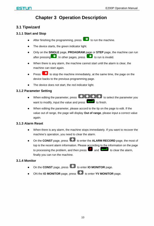
3.1.4 Monitor
On the CONST page, press to enter IO MONITOR page.
ON the IO MONITOR page, press to enter YV MONITOR page.

E200P Operation Manual
11
3.2 Operation Flow Power
on
Single-Step Manual Single Run
Programs Mutil-Step Mutil-Step Run
CONST
System
ParameterDIAGNOSE
IO MONITOR YV MONITORALARM
RECORD
Password: 14789 Password: 5656
PPress Press
lPress
lPress
Press
PressPressPressPress
Press PressPressPress
PPress
PPress
PPress
TchIn PARA
Password: 1212
CONFIG PARA.
Password: 36987
PPress
Figure 3-1 Operation Flow
3.3 Single-Step
In the actual processing, operator user pedal switch to control the bending
process. Because of the SINGLE page has simple and direct parameter, it more
suitable for the bending operation just only one-step.
When the E200P device is electrified, wait a few seconds into the SINGLE page
(Default page), as shown in Figure 3-2.
[Operation guide]:
Press to select the parameter you want to modify, input the
value and press to finish the operation.
After finishing the editing, press to run the machine, the page on the device
enters to RUN page.
Press to stop the machine. The page on the device enters to SINGLE page.
E200P Operation Manual
12
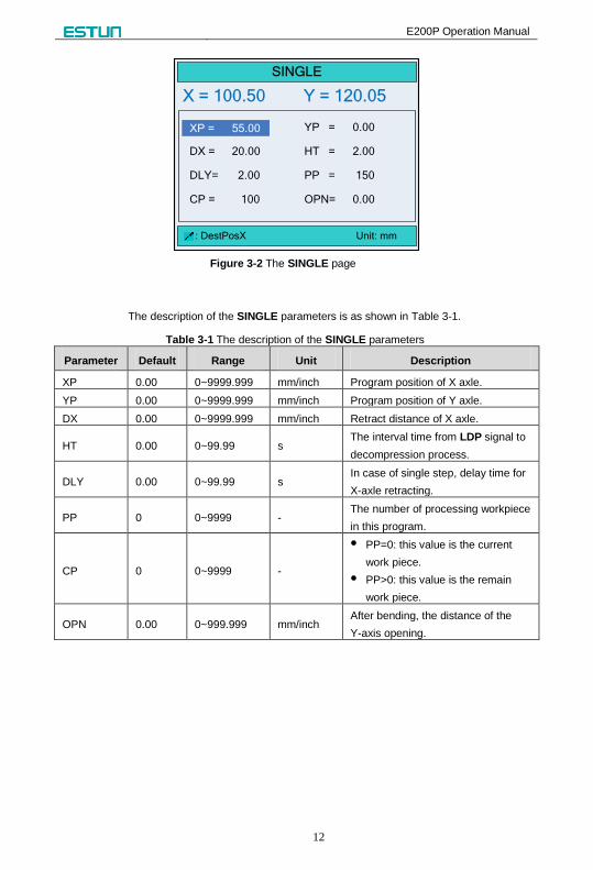
SINGLE
: DestPosX Unit: mm
X = 100.50 Y = 120.05
XP = 55.00 YP = 0.00
DX = 20.00 HT = 2.00
DLY= 2.00 PP = 150
CP = 100 OPN= 0.00
XP = 55.00
Figure 3-2 The SINGLE page
The description of the SINGLE parameters is as shown in Table 3-1.
Table 3-1 The description of the SINGLE parameters
Parameter Default Range Unit Description
XP 0.00 0~9999.999 mm/inch Program position of X axle.
YP 0.00 0~9999.999 mm/inch Program position of Y axle.
DX 0.00 0~9999.999 mm/inch Retract distance of X axle.
HT 0.00 0~99.99 s The interval time from LDP signal to
decompression process.
DLY 0.00 0~99.99 s In case of single step, delay time for
X-axle retracting.
PP 0 0~9999 - The number of processing workpiece
in this program.
CP 0 0~9999 -
PP=0: this value is the current
work piece.
PP>0: this value is the remain
work piece.
OPN 0.00 0~999.999 mm/inch After bending, the distance of the
Y-axis opening.

E200P Operation Manual
13
3.4 Multi-Step
In the actual processing, operator user pedal switch to control the bending
process. In PROGRAM page, you can finish the complex operation with carefully
programmed.
Step 1 When the E200P device is electrified, wait a few seconds into the SINGLE page
(Default page).
Step 2 Press to enter the PROGRAMS page, as shown in Figure 3-3.
[Operation Guide]
- Program-Number is used for storing Mutil-Step programming, in order to work
again. E200P CNC device provide 40 Program-Number to user.
- Press to select the target Program-Number and press
to enter, and then the editorial content is automatically saved in this
program.
PROGRAMS 0 P
: 1program 1 ST
1 2 53 4
11 12 1513 14
6 7 108 9
16 17 2018 19
Figure 3-3 The PROGRAMS page
Step 3 Select the target Program-Number, such as 2program and press to enter
PROGRAM page, as shown in Figure 3-4.
[Operation Guide]: Press to select the parameter you want to modify, input
the value and press to finish the operation.

E200P Operation Manual
14
NO.2 PROGRAM
:
X= 10.00 Y = 10.00
ST: 3 STEP
PP: 0 PIECE
CP: 50 PIECE
DLY: 4.00 S
HT: 2.00 S
Figure 3-4 The PROGRAM page
The description of the PROGRAM parameters is as shown in Figure 3-2.
Table 3-2 The description of the PROGRAM parameters
Parameter Default Range Unit Description
ST 1 0~25 - The total number of steps in this program.
PP 0 0~99999 - The number of processing workpiece in this
program.
CP 0 0~99999 - PP=0: this value is the current work piece.
PP>0: this value is the remain work piece.
DLY 0.00 0~99.99 s In case of single step, delay time for X-axle
retracting.
HT 0.0 0~99.99 s The interval time from LDP signal to
decompression process.
Step 4 After finishing the setting of the PROGRAM page, press to enter STEP page, as
shown in Figure 3-5.
[Operation Guide]:
It automatically makes the step number, according to the value of parameter ST on
the PROGRAM page.
Please pay attention the sequence of the step, e.g. 1 / 3ST: 1 indicates the current
step, 3 indicates the total step. The machine will run in sequence.
Press to enter each step page for editing.
Press to select the parameter you want to modify, input the value and
press to finish the operation.
Press back to PROGRAM page.

E200P Operation Manual
15
PROGRAM2 1 / 3ST
:
X= 10.00 Y = 10.00
XP: 50.00 mm
YP: 85.00 mm
DX: 50.00 mm
OPEN DIST: 0.00 mm
Repeat Times: 1 TIMES
Figure 3-5 The STEP page
The description of STEP parameters is as shown in Table 3-3.
Table 3-3 The description of Step parameters
Parameter Default Range Unit Description
XP 0.00 0~9999.999 mm/inch Program position of X-axis.
YP 0.00 0~9999.999 mm/inch Program position of Y-axis.
DX 0.00 0~9999.999 mm/inch Retract distance of X axle.
OPEN DIST 0.00 0~999.999 mm/inch After bending, the distance of the
Y-axis opening.
Repeat Times 1 1~99 - The repeat times in this step.
Step 5 After finishing operation, you can accord the actual situation to run the machine.
- If you want to run the machine from a certain step, press arrow key to switch
that step page, Press to run, the device enters RUN page.
- If you want to run the machine in in sequence, press back to PROGRAM
page, and then Press to run, the device enters RUN page.
----End

E200P Operation Manual
16
3.5 Manual
In general, operator wants to adjust the backgauge or the block, need to enter
MANUAL page to do relevant operation.
When the E200P device is electrified, wait a few seconds into the SINGLE page
(Default page), press or enter MANUAL page, as shown in Figure 3-6.
[Operation Guide]:
Move the cursor and stay on the axis you want to adjust, press and hold , the
motor control this axis runs to the increment count direction slowly.
Move the cursor and stay on the axis you want to adjust, press and hold , the
motor control this axis runs to the decrement count direction slowly.
Move the cursor and stay on the axis you want to adjust, press and hold
and , the motor control this axis runs to the increment count direction quickly.
Move the cursor and stay on the axis you want to adjust, press and hold
and , the motor control this axis runs to the decrement count direction quickly.
MANUAL
: Unit: mm
X= 10.00
Y= 10.00
Figure 3-6 The MANUAL page

E200P Operation Manual
17
3.6 Alarm and Monitor
On the CONST page, press to enter IO MONITOR page, as shown in Figure
3-7.
程 程
IO程 程 程 程 程 程
程 程 程 程 01 02 03 04 05 06 07 08 09 10 INPUT程 11 12 13 14 15 16 17 18 19 20
程 程 程 程 01 02 03 04 05 06 07 08 09 10 OUTPUT程 11 12 13 14 15 16 17 18 19 20
程 程 程 程 程 程 程 AI程 程 程 程 程 程
程 程
IO程 程 程 程 程 程
程 程 程 程 01 02 03 04 05 06 07 08 09 10 INPUT程 11 12 13 14 15 16 17 18 19 20
程 程 程 程 01 02 03 04 05 06 07 08 09 10 OUTPUT程 11 12 13 14 15 16 17 18 19 20
IO MONITOR
INPUTS
INPUT:
OUTPUTS
OUTPUT:
ST PS PD PU MD SI MR NC
Y1 Y2 Y3 Y4 Y5 EH ER
Figure 3-7 The IO MONITOR page
On the CONST page, press to enter ALARM RECORD page, as shown in
Figure 3-8.
程 程 程 程 程 程
IO程 程 程 程 程 程
程 程 程 程 程 程 程 AI程 程 程 程 程 程
程 程 程 程 程 程
IO程 程 程 程 程 程 ALARM RECORD
NO. REASON
A.22 Mach. Not ready
Figure 3-8 The ALARM RECORD page
On the CONST page, press two times to enter YV MONITOR page, as
shown in Figure 3-9.

E200P Operation Manual
18
YV MONITOR
:
NAME
NOW
CLSD
PRESS
DECMP
YV1 YV2 YV3 YV4 YV5
OPEN
Figure 3-9 The YV MONITOR page
E200P Operation Manual
19
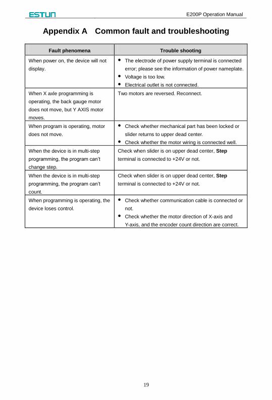
Appendix A Common fault and troubleshooting
Fault phenomena Trouble shooting
When power on, the device will not
display.
The electrode of power supply terminal is connected
error; please see the information of power nameplate.
Voltage is too low.
Electrical outlet is not connected.
When X axle programming is
operating, the back gauge motor
does not move, but Y AXIS motor
moves.
Two motors are reversed. Reconnect.
When program is operating, motor
does not move.
Check whether mechanical part has been locked or
slider returns to upper dead center.
Check whether the motor wiring is connected well.
When the device is in multi-step
programming, the program can’t
change step.
Check when slider is on upper dead center, Step
terminal is connected to +24V or not.
When the device is in multi-step
programming, the program can’t
count.
Check when slider is on upper dead center, Step
terminal is connected to +24V or not.
When programming is operating, the
device loses control.
Check whether communication cable is connected or
not.
Check whether the motor direction of X-axis and
Y-axis, and the encoder count direction are correct.

E200P Operation Manual
20
Appendix B Alarm List
Alarm NO. Alarm Information Alarm Description
A.01 Pieces reached Normal message, that the count reaches a preset value.
A.02 XPos < minimum The current position of X-axis beyond the minimum
value, need manually adjust to the soft limit range.
A.03 XPos > maximum The current position of X-axis or beyond the maximum
value, need manually adjust to the soft limit range.
A.04 YPos < minimum The current position of Y-axis beyond the minimum
value, need manually adjust to the soft limit range.
A.05 YPos > maximum The current position of Y-axis or beyond the maximum
value, need manually adjust to the soft limit range.
A.06 Out of UDP Move the slider to the upper dead point by foot witch.
A.11 Slider Block err. The slider block has been off the upper limit position
when the Y-axis is in positioning.
A.12 Finished work The count reaches the preset value, need to manually
clear alarm.
A.22 Mach. Not ready Need to start the pump power.
A.23 Encoder abnor. The voltage of encoder is abnormal, please check it.
A.24 Comm. Err. Can communication is abnormal, please check whether
the communication port ground is well.
A.25 X-axis Dropped The X-axis driver is missing, need to power on system
and drive again.
A.26 Y-axis Dropped The Y-axis driver is missing, need to power on system
and drive again.
A.27 Can Send Err. The device is not connected to the drive, please
connect the drive.
A.28 Mode Err. That has Switched system in the process of operation
mode, clear the alarm after the restart.
A.29 SafeIn Err. Light signal loss on the CLOSED stage, check the
screen input signal with or without object light signal.
A.30 Power Drop The system voltage is lower than the normal value,
check whether the system voltage is normal.
A.32 Axis Droped When the driven mode is EDS, the drive is offline.
A.51 Drive off
‘Clr+Enter’Reset The main power of servo drive has been off.
AX.60~AX.67 CAN Error The X-axis CAN communication is abnormal, restarting
the system after clearing the alarm.
AY.60~AY.66 CAN Error The Y-axis CAN communication is abnormal, restarting
the system after clearing the alarm.

E200P Operation Manual
21
Appendix C Parameter Description
Parameter Default Range Unit Description
CONST
mm/inch 0 0~1 - 0: mm
1: inch
中文/English 0 0~1 - 0: 中文
1: English
Release Delay 0.50 s
The delay time for the slide
releasing the pressure after
bending.
Hold Delay 0.00 0.00~99.99 s
The default interval time
from LDP signal to
decompression process.
If the parameter HT on the
Single-Step page or the
Multi-Step page is set to 0,
this parameter value is valid.
Retract Delay 0.00 0.00~99.99 s The delay time for the back
gauge will go to retract.
Version - - - The current software version
number.
TchIn PARA
X-tea. in 10.00 0~9999.999 mm/inch
When the teaching of X-axis
is enabling, the operator
assigns to the X-axis of a
correct value, to represent
the backgauge current
position.
Y-tea. in 10.00 0~9999.999 mm/inch
When the teaching of Y-axis
is enabling, the operator
assigns to the Y-axis of a
correct value, to represent
the slider current position.
CONFIG PARA.
YV5->NCRDY 0 0, 1 -
0: Disable, the function of
YV output is normal.
1: Enable, the function of
YV output is changed to
NCRDY output.
E200P Operation Manual
22
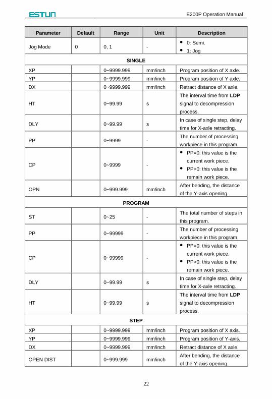
Parameter Default Range Unit Description
Jog Mode 0 0, 1 - 0: Semi.
1: Jog
SINGLE
XP 0~9999.999 mm/inch Program position of X axle.
YP 0~9999.999 mm/inch Program position of Y axle.
DX 0~9999.999 mm/inch Retract distance of X axle.
HT 0~99.99 s
The interval time from LDP
signal to decompression
process.
DLY 0~99.99 s In case of single step, delay
time for X-axle retracting.
PP 0~9999 - The number of processing
workpiece in this program.
CP 0~9999 -
PP=0: this value is the
current work piece.
PP>0: this value is the
remain work piece.
OPN 0~999.999 mm/inch After bending, the distance
of the Y-axis opening.
PROGRAM
ST 0~25 - The total number of steps in
this program.
PP 0~99999 - The number of processing
workpiece in this program.
CP 0~99999 -
PP=0: this value is the
current work piece.
PP>0: this value is the
remain work piece.
DLY 0~99.99 s In case of single step, delay
time for X-axle retracting.
HT 0~99.99 s
The interval time from LDP
signal to decompression
process.
STEP
XP 0~9999.999 mm/inch Program position of X axis.
YP 0~9999.999 mm/inch Program position of Y-axis.
DX 0~9999.999 mm/inch Retract distance of X axle.
OPEN DIST 0~999.999 mm/inch After bending, the distance
of the Y-axis opening.

E200P Operation Manual
23
Parameter Default Range Unit Description
Repeat Times 1~99 - The repeat times in this
step.
