eichenbergergewinde - movetec oy4 © eichenberger gewinde ag – v 12 01 30 d 0 x p fbe 42–45 zye...
TRANSCRIPT
EichenbergerGewinde
100 % Swiss made
Carry ball screws Carry Speed-line high-helix ball screws
Speedy high-helix lead screwsRondo round thread lead screws
Main Catalogue
3© Eichenberger Gewinde AG – V 12 01 30
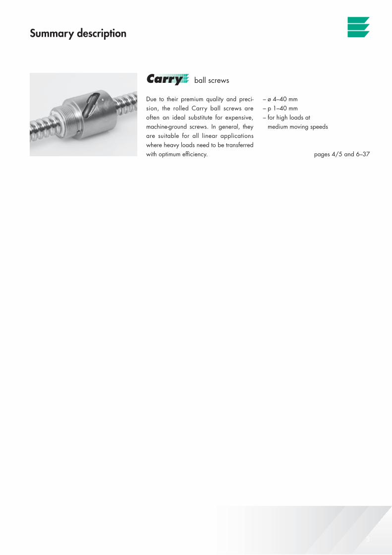
ball screws
Due to their premium quality and preci-sion, the rolled Carry ball screws are often an ideal substitute for expensive, machine-ground screws. In general, they are suitable for all linear applications where heavy loads need to be transferred with optimum efficiency.
– ø 4–40 mm– p 1–40 mm– for high loads at medium moving speeds
pages 4/5 and 6–37
The cold-rolled, wear-resistant Carry Speed-line are marked by an extremely high helix. They provide for high moving speeds and deliver an efficiency which is nothing short of impressive.
– ø 8–25 mm– p 10–50 mm– for medium loads at high moving speeds
pages 4/5 and 38–47
The innovative Speedy high-helix lead screws with helix up to 6 x diameter pro-vide for maximum moving speeds at low rotational speeds or efficient conversion of linear to rotary movements.
– ø 4–36 mm– p 4–200 mm– for low loads at high moving speeds– slide screw unit
pages 48/49 and 50–71
The alternative to trapezoidal screws with remarkable efficiency.
– ø 6–16 mm– p 2–5 mm– for medium loads at medium moving speeds– slide screw unit
pages 48/49 and 72–76
Summary description
high-helix ball screws
high-helix lead screws
round thread lead screws
Eichenberger Gewinde AG page 79
Contract work:
About the Company:
pages 77/78
4 © Eichenberger Gewinde AG – V 12 01 30
d 0 x p
FBE
42–4
5ZY
E40
/41
FBR
26–3
1FB
I22
–25
FGR
16–2
1FG
I12
–15
ZYR
10/1
1ZY
I8/
9
d 0 x p
4 x
1n
n 4
x 1
5 x
2l
n 5
x 2
5 x
3l
5 x
3
6 x
1n
n 6
x 1
6 x
2l
2) 6
x 2
8 x
1n
n 8
x 1
8 x
1.5
ln
8 x
1.5
8 x
2n
nl
ln
n 8
x 2
8 x
2.5
ll
n 8
x 2
.5
8 x
3l
n 8
x 3
8 x
5l
n 8
x 5
8 x
8n
l 8
x 8
8 x
12
nn
8 x
12
10 x
2l
2)l
2)n
2)10
x 2
10 x
3l
2)n
2)10
x 3
10 x
4n
ln
10 x
4
10 x
10
nl
n10
x 1
0
12 x
2n
l 2)
n 2)
12 x
2
12 x
3n
12 x
3
12 x
4n
ll
n12
x 4
12 x
5n
nl
2)l
12 x
5
12.7
x 1
2.7
l12
.7 x
12.
7
12.7
x 2
5.4
nn
12.7
x 2
5.4
14 x
2n
l14
x 2
14 x
4n
2)l
2)l
n 2)
n14
x 4
16 x
2n
ll
2)16
x 2
16 x
5n
2)l
2)l
2)n
2)16
x 5
16 x
10
nn
nl
n16
x 1
0
16 x
16
nn
16 x
16
16 x
50
nn
16 x
50
20 x
2l
2)20
x 2
20 x
5n
2)l
l 2)
n 2)
20 x
5
20 x
10
nl
20 x
10
20 x
20
nn
nl
20 x
20
25 x
5n
ln
25 x
5
25 x
10
nl
25 x
10
25 x
25
nn
nl
25 x
25
32 x
5n
ln
32 x
5
32 x
10
nl
32 x
10
32 x
15
n32
x 1
5
32 x
32
n32
x 3
2
40 x
5n
40 x
5
40 x
20
n40
x 2
0
40 x
40
n40
x 4
0
d 0 x p
FBE
42–4
5ZY
E40
/41
FBR
26–3
1FB
I22
–25
FGR
16–2
1FG
I12
–15
ZYR
10/1
1ZY
I8/
9
d 0 x p
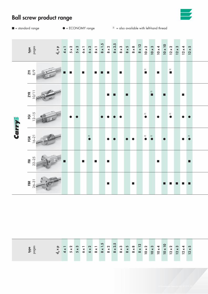
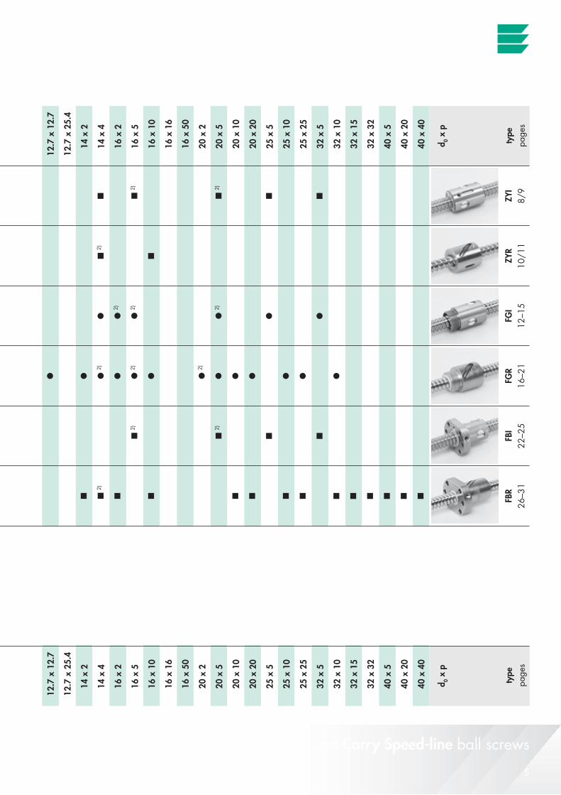
Ball screw product range
= standard range l = ECONOMY range 2) = also available with left-hand threadty
pepa
ges
type
page
s
Carry and Carry Speed-line ball screws
5© Eichenberger Gewinde AG – V 12 01 30
d 0 x p
FBE
42–4
5ZY
E40
/41
FBR
26–3
1FB
I22
–25
FGR
16–2
1FG
I12
–15
ZYR
10/1
1ZY
I8/
9
d 0 x p
4 x
1n
n 4
x 1
5 x
2l
n 5
x 2
5 x
3l
5 x
3
6 x
1n
n 6
x 1
6 x
2l
2) 6
x 2
8 x
1n
n 8
x 1
8 x
1.5
ln
8 x
1.5
8 x
2n
nl
ln
n 8
x 2
8 x
2.5
ll
n 8
x 2
.5
8 x
3l
n 8
x 3
8 x
5l
n 8
x 5
8 x
8n
l 8
x 8
8 x
12
nn
8 x
12
10 x
2l
2)l
2)n
2)10
x 2
10 x
3l
2)n
2)10
x 3
10 x
4n
ln
10 x
4
10 x
10
nl
n10
x 1
0
12 x
2n
l 2)
n 2)
12 x
2
12 x
3n
12 x
3
12 x
4n
ll
n12
x 4
12 x
5n
nl
2)l
12 x
5
12.7
x 1
2.7
l12
.7 x
12.
7
12.7
x 2
5.4
nn
12.7
x 2
5.4
14 x
2n
l14
x 2
14 x
4n
2)l
2)l
n 2)
n14
x 4
16 x
2n
ll
2)16
x 2
16 x
5n
2)l
2)l
2)n
2)16
x 5
16 x
10
nn
nl
n16
x 1
0
16 x
16
nn
16 x
16
16 x
50
nn
16 x
50
20 x
2l
2)20
x 2
20 x
5n
2)l
l 2)
n 2)
20 x
5
20 x
10
nl
20 x
10
20 x
20
nn
nl
20 x
20
25 x
5n
ln
25 x
5
25 x
10
nl
25 x
10
25 x
25
nn
nl
25 x
25
32 x
5n
ln
32 x
5
32 x
10
nl
32 x
10
32 x
15
n32
x 1
5
32 x
32
n32
x 3
2
40 x
5n
40 x
5
40 x
20
n40
x 2
0
40 x
40
n40
x 4
0
d 0 x p
FBE
42–4
5ZY
E40
/41
FBR
26–3
1FB
I22
–25
FGR
16–2
1FG
I12
–15
ZYR
10/1
1ZY
I8/
9
d 0 x p
Carry and Carry Speed-line ball screws
type
page
sty
pepa
ges
6 © Eichenberger Gewinde AG – V 12 01 30
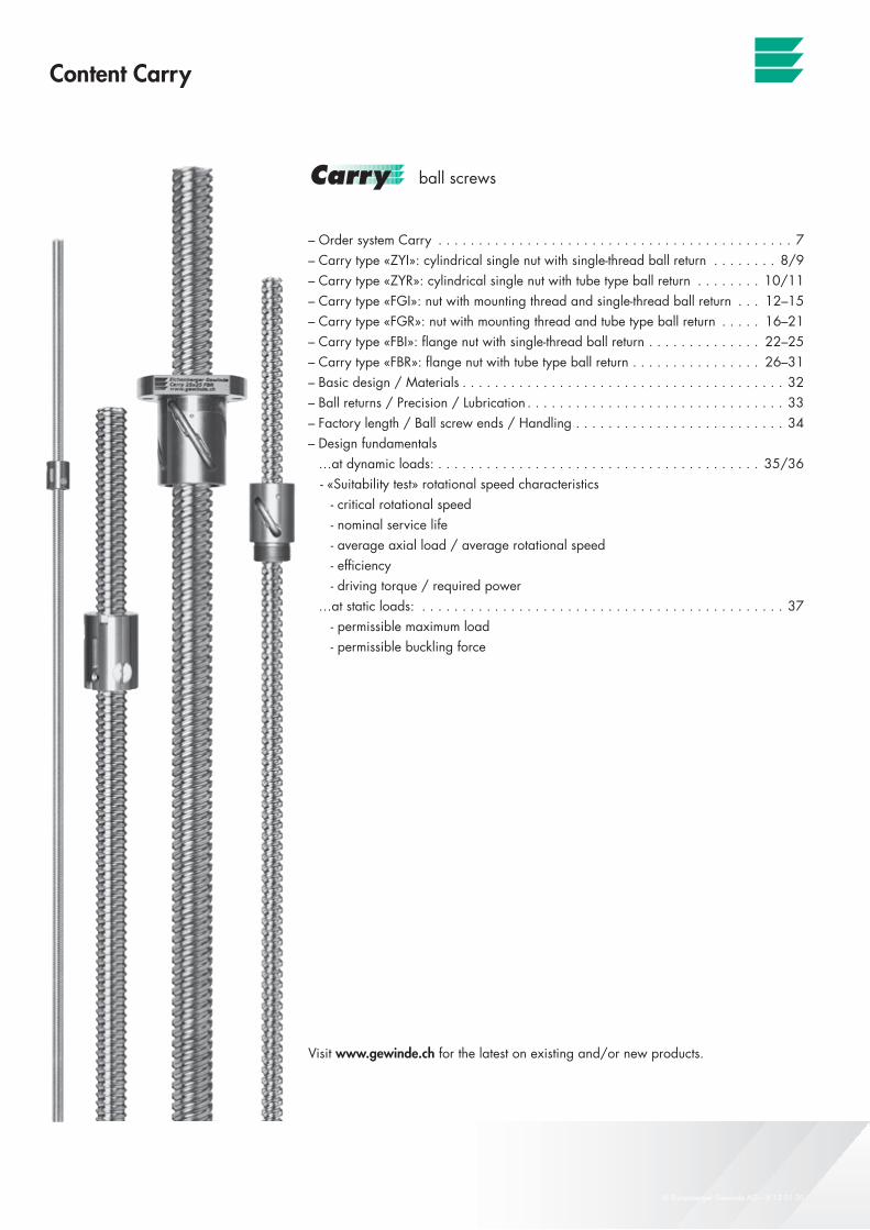
Content Carry
– Order system Carry . . . . . . . . . . . . . . . . . . . . . . . . . . . . . . . . . . . . . . . . . . . . 7– Carry type «ZYI»: cylindrical single nut with single-thread ball return . . . . . . . . 8/9– Carry type «ZYR»: cylindrical single nut with tube type ball return . . . . . . . . 10/11– Carry type «FGI»: nut with mounting thread and single-thread ball return . . . 12–15– Carry type «FGR»: nut with mounting thread and tube type ball return . . . . . 16–21– Carry type «FBI»: flange nut with single-thread ball return . . . . . . . . . . . . . . 22–25– Carry type «FBR»: flange nut with tube type ball return . . . . . . . . . . . . . . . . 26–31– Basic design / Materials . . . . . . . . . . . . . . . . . . . . . . . . . . . . . . . . . . . . . . . . 32– Ball returns / Precision / Lubrication . . . . . . . . . . . . . . . . . . . . . . . . . . . . . . . . 33– Factory length / Ball screw ends / Handling . . . . . . . . . . . . . . . . . . . . . . . . . . 34– Design fundamentals …at dynamic loads: . . . . . . . . . . . . . . . . . . . . . . . . . . . . . . . . . . . . . . . . 35/36 - «Suitability test» rotational speed characteristics - critical rotational speed - nominal service life - average axial load / average rotational speed - efficiency - driving torque / required power …at static loads: . . . . . . . . . . . . . . . . . . . . . . . . . . . . . . . . . . . . . . . . . . . . . 37 - permissible maximum load - permissible buckling force
ball screws
Visit www.gewinde.ch for the latest on existing and/or new products.
Carry ball screws
7© Eichenberger Gewinde AG – V 12 01 30
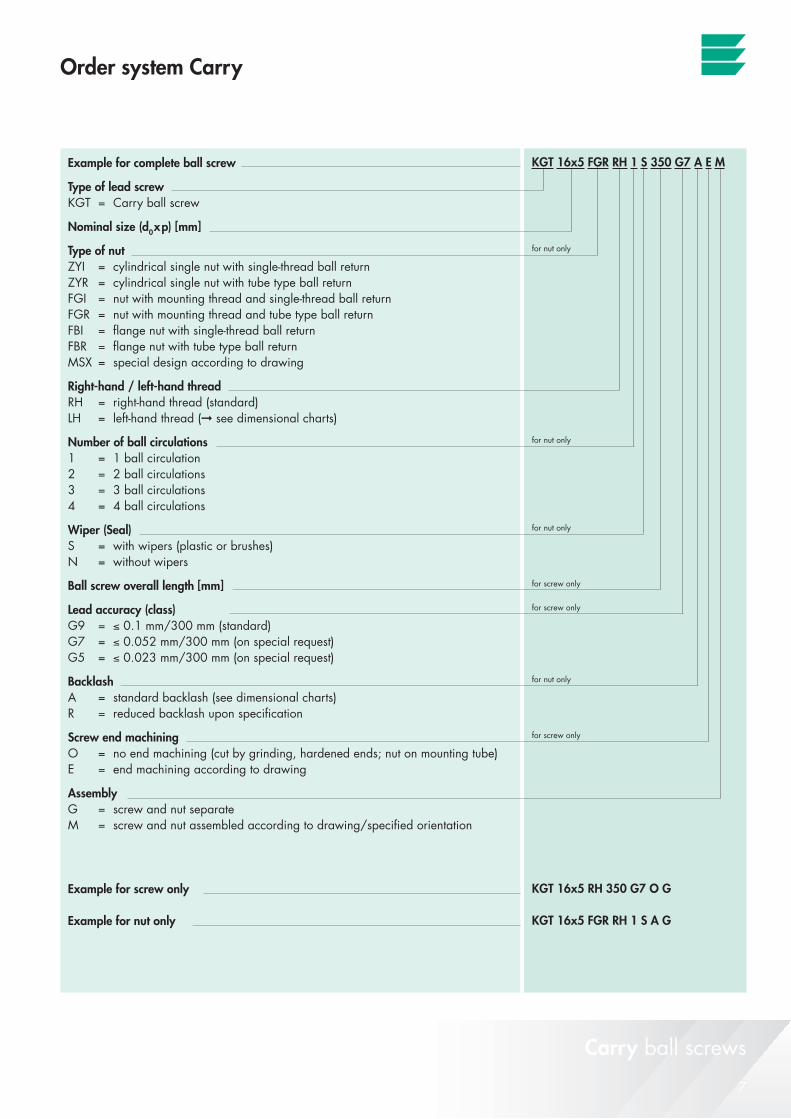
Order system Carry
Example for complete ball screw
Type of lead screwKGT = Carry ball screw
Nominal size (d0xp) [mm]
Type of nutZYI = cylindrical single nut with single-thread ball returnZYR = cylindrical single nut with tube type ball returnFGI = nut with mounting thread and single-thread ball returnFGR = nut with mounting thread and tube type ball returnFBI = flange nut with single-thread ball returnFBR = flange nut with tube type ball returnMSX = special design according to drawing
Right-hand / left-hand threadRH = right-hand thread (standard)LH = left-hand thread (➞ see dimensional charts)
Number of ball circulations1 = 1 ball circulation 2 = 2 ball circulations 3 = 3 ball circulations 4 = 4 ball circulations Wiper (Seal)S = with wipers (plastic or brushes)N = without wipers
Ball screw overall length [mm]
Lead accuracy (class)G9 = ≤ 0.1 mm/300 mm (standard)G7 = ≤ 0.052 mm/300 mm (on special request)G5 = ≤ 0.023 mm/300 mm (on special request)
BacklashA = standard backlash (see dimensional charts)R = reduced backlash upon specification
Screw end machiningO = no end machining (cut by grinding, hardened ends; nut on mounting tube)E = end machining according to drawing
AssemblyG = screw and nut separateM = screw and nut assembled according to drawing/specified orientation
Example for screw only
Example for nut only
KGT 16x5 FGR RH 1 S 350 G7 A E M
KGT 16x5 RH 350 G7 O G
KGT 16x5 FGR RH 1 S A G
for nut only
for nut only
for nut only
for screw only
for screw only
for nut only
for screw only
Carry ball screws
8 © Eichenberger Gewinde AG – V 12 01 30
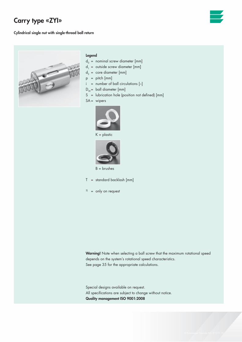
Carry type «ZYI»
Cylindrical single nut with single-thread ball return
Legendd0 = nominal screw diameter [mm]d1 = outside screw diameter [mm]d2 = core diameter [mm]p = pitch [mm]i = number of ball circulations [–]DW = ball diameter [mm]S = lubrication hole (position not defined) [mm]SA = wipers
K = plastic
B = brushes
T = standard backlash [mm]
3) = only on request
Warning! Note when selecting a ball screw that the maximum rotational speed depends on the system’s rotational speed characteristics.See page 35 for the appropriate calculations.
Special designs available on request. All specifications are subject to change without notice.Quality management ISO 9001:2008
Carry ball screws
9© Eichenberger Gewinde AG – V 12 01 30
Carry
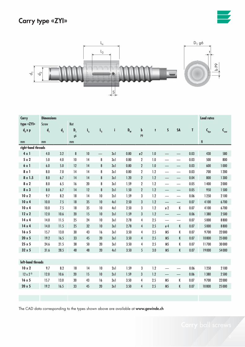
d0 x p d1 d2 D1 Ln L3 i DW b t S SA T g6 P9
mm mm mm N
4 x 1 4.0 3.2 8 10 — 3x1 0.80 ø 2 1.0 — — 0.03 430 580
5 x 2 5.0 4.0 10 14 8 3x1 0.80 2 1.0 — — 0.03 500 800
6 x 1 6.0 5.0 12 14 8 3x1 0.80 2 1.0 — — 0.03 600 1 000
8 x 1 8.0 7.0 14 14 8 3x1 0.80 2 1.2 — — 0.03 700 1 200
8 x 1.5 8.0 6.7 14 14 8 3x1 1.20 2 1.2 — — 0.04 800 1 300
8 x 2 8.0 6.5 16 20 8 3x1 1.59 2 1.2 — — 0.05 1 400 2 000
8 x 3 8.0 6.7 14 12 8 2x1 1.50 2 1.2 — — 0.05 950 1 500
10 x 2 9.7 8.2 18 14 10 2x1 1.59 3 1.2 — — 0.06 1 250 2 100
10 x 4 10.0 7.5 18 35 10 4x1 2.50 3 1.2 — — 0.07 4 100 6 700
10 x 4 10.0 7.5 18 35 10 4x1 2.50 3 1.2 ø 2 K 0.07 4 100 6 700
12 x 2 12.0 10.6 20 15 10 2x1 1.59 3 1.2 — — 0.06 1 380 2 500
14 x 4 14.0 11.5 25 24 10 3x1 2.78 4 2.5 — — 0.07 5 000 8 800
14 x 4 14.0 11.5 25 32 10 3x1 2.78 4 2.5 ø 4 K 0.07 5 000 8 800
16 x 5 15.7 13.0 30 43 16 3x1 3.50 4 2.5 M5 K 0.07 9 700 22 000
20 x 5 19.2 16.5 33 45 20 3x1 3.50 4 2.5 M5 K 0.07 10 800 25 000
25 x 5 24.6 21.5 38 50 20 3x1 3.50 4 2.5 M5 K 0.07 11 700 30 000
32 x 5 31.6 28.5 48 48 20 4x1 3.50 5 3.0 M5 K 0.07 19 000 54 000
10 x 2 9.7 8.2 18 14 10 2x1 1.59 3 1.2 — — 0.06 1 250 2 100
12 x 2 3) 12.0 10.6 20 15 10 2x1 1.59 3 1.2 — — 0.06 1 380 2 500
16 x 5 15.7 13.0 30 43 16 3x1 3.50 4 2.5 M5 K 0.07 9 700 22 000
20 x 5 19.2 16.5 33 45 20 3x1 3.50 4 2.5 M5 K 0.07 10 800 25 000
Carry type «ZYI»
Carry ball screws
The CAD data corresponding to the types shown above are available at www.gewinde.ch
Dimensions Load rates
type «ZYI» Screw Nut
Cdyn Cstat
right-hand threads
left-hand threads
10 © Eichenberger Gewinde AG – V 12 01 30
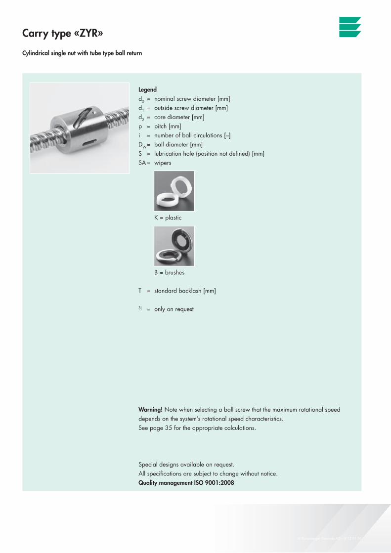
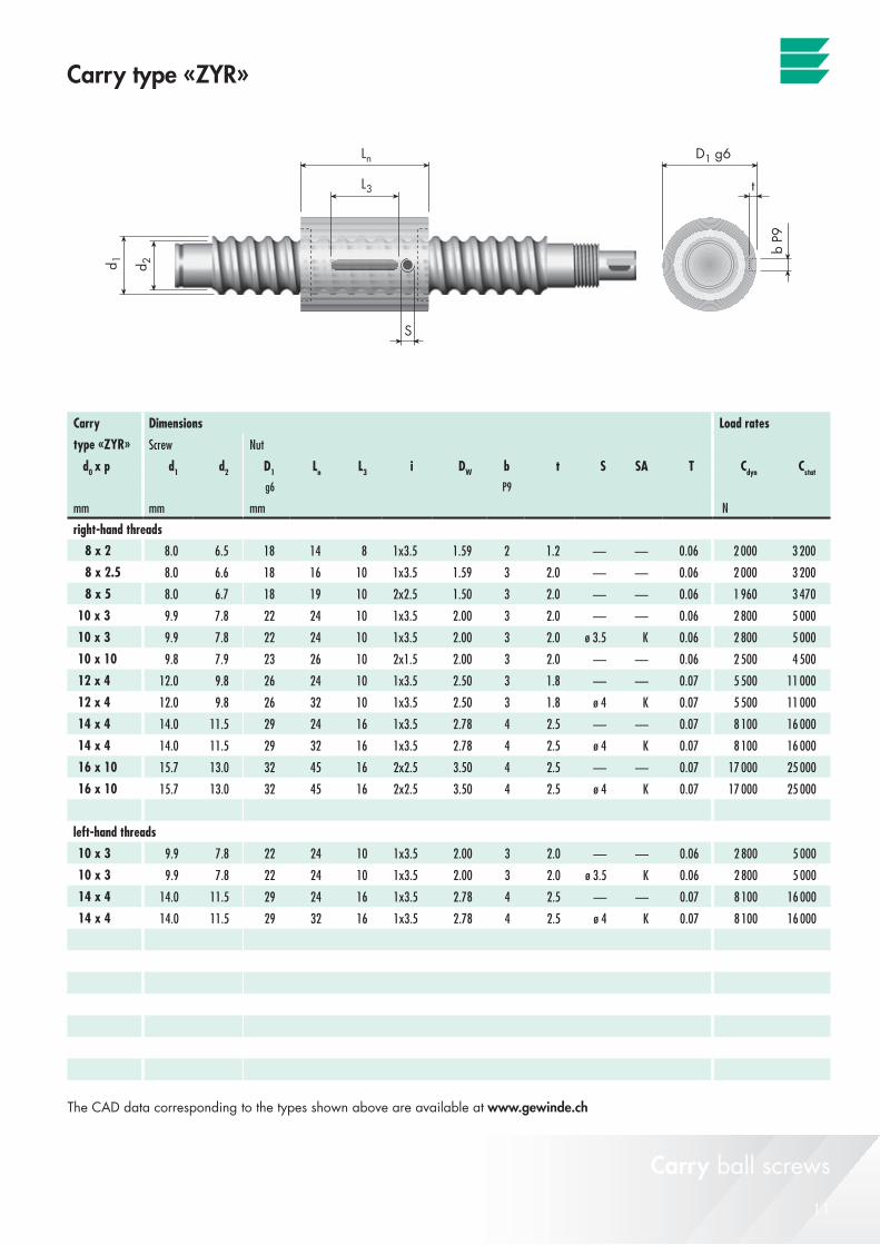
Carry type «ZYR»
Cylindrical single nut with tube type ball return
Legendd0 = nominal screw diameter [mm]d1 = outside screw diameter [mm]d2 = core diameter [mm]p = pitch [mm]i = number of ball circulations [–]DW = ball diameter [mm]S = lubrication hole (position not defined) [mm]SA = wipers
K = plastic
B = brushes
T = standard backlash [mm]
3) = only on request
Warning! Note when selecting a ball screw that the maximum rotational speed depends on the system’s rotational speed characteristics.See page 35 for the appropriate calculations.
Special designs available on request. All specifications are subject to change without notice.Quality management ISO 9001:2008
Carry ball screws
11© Eichenberger Gewinde AG – V 12 01 30
Carry
d0 x p d1 d2 D1 Ln L3 i DW b t S SA T g6 P9
mm mm mm N
8 x 2 8.0 6.5 18 14 8 1x3.5 1.59 2 1.2 — — 0.06 2 000 3 200
8 x 2.5 8.0 6.6 18 16 10 1x3.5 1.59 3 2.0 — — 0.06 2 000 3 200
8 x 5 8.0 6.7 18 19 10 2x2.5 1.50 3 2.0 — — 0.06 1 960 3 470
10 x 3 9.9 7.8 22 24 10 1x3.5 2.00 3 2.0 — — 0.06 2 800 5 000
10 x 3 9.9 7.8 22 24 10 1x3.5 2.00 3 2.0 ø 3.5 K 0.06 2 800 5 000
10 x 10 9.8 7.9 23 26 10 2x1.5 2.00 3 2.0 — — 0.06 2 500 4 500
12 x 4 12.0 9.8 26 24 10 1x3.5 2.50 3 1.8 — — 0.07 5 500 11 000
12 x 4 12.0 9.8 26 32 10 1x3.5 2.50 3 1.8 ø 4 K 0.07 5 500 11 000
14 x 4 14.0 11.5 29 24 16 1x3.5 2.78 4 2.5 — — 0.07 8 100 16 000
14 x 4 14.0 11.5 29 32 16 1x3.5 2.78 4 2.5 ø 4 K 0.07 8 100 16 000
16 x 10 15.7 13.0 32 45 16 2x2.5 3.50 4 2.5 — — 0.07 17 000 25 000
16 x 10 15.7 13.0 32 45 16 2x2.5 3.50 4 2.5 ø 4 K 0.07 17 000 25 000
10 x 3 9.9 7.8 22 24 10 1x3.5 2.00 3 2.0 — — 0.06 2 800 5 000
10 x 3 9.9 7.8 22 24 10 1x3.5 2.00 3 2.0 ø 3.5 K 0.06 2 800 5 000
14 x 4 14.0 11.5 29 24 16 1x3.5 2.78 4 2.5 — — 0.07 8 100 16 000
14 x 4 14.0 11.5 29 32 16 1x3.5 2.78 4 2.5 ø 4 K 0.07 8 100 16 000
Carry type «ZYR»
Carry ball screws
The CAD data corresponding to the types shown above are available at www.gewinde.ch
Dimensions Load rates
type «ZYR» Screw Nut
Cdyn Cstat
right-hand threads
left-hand threads
12 © Eichenberger Gewinde AG – V 12 01 30
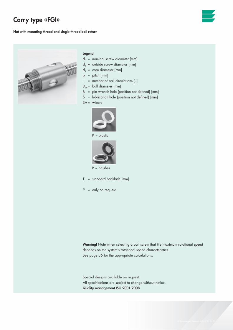
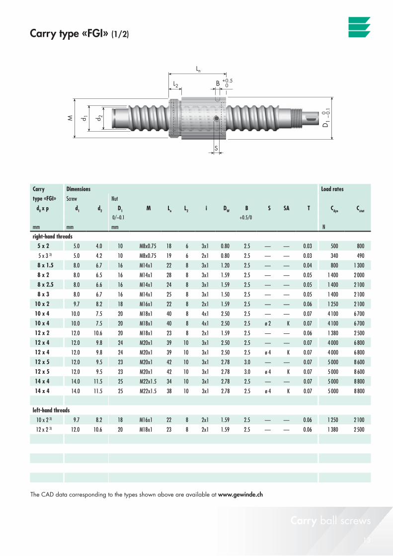
Carry type «FGI»
Nut with mounting thread and single-thread ball return
Legendd0 = nominal screw diameter [mm]d1 = outside screw diameter [mm]d2 = core diameter [mm]p = pitch [mm]i = number of ball circulations [–]DW = ball diameter [mm]B = pin wrench hole (position not defined) [mm]S = lubrication hole (position not defined) [mm]SA = wipers
K = plastic
B = brushes
T = standard backlash [mm]
3) = only on request
Warning! Note when selecting a ball screw that the maximum rotational speed depends on the system’s rotational speed characteristics.See page 35 for the appropriate calculations.
Special designs available on request. All specifications are subject to change without notice.Quality management ISO 9001:2008
Carry ball screws
13© Eichenberger Gewinde AG – V 12 01 30
Carry
d0 x p d1 d2 D1 M Ln L2 i DW B S SA T 0/–0.1 +0.5/0
mm mm mm N
5 x 2 5.0 4.0 10 M8x0.75 18 6 3x1 0.80 2.5 — — 0.03 500 800
5 x 3 3) 5.0 4.2 10 M8x0.75 19 6 2x1 0.80 2.5 — — 0.03 340 490
8 x 1.5 8.0 6.7 16 M14x1 22 8 3x1 1.20 2.5 — — 0.04 800 1 300
8 x 2 8.0 6.5 16 M14x1 28 8 3x1 1.59 2.5 — — 0.05 1 400 2 000
8 x 2.5 8.0 6.6 16 M14x1 24 8 3x1 1.59 2.5 — — 0.05 1 400 2 100
8 x 3 8.0 6.7 16 M14x1 25 8 3x1 1.50 2.5 — — 0.05 1 400 2 100
10 x 2 9.7 8.2 18 M16x1 22 8 2x1 1.59 2.5 — — 0.06 1 250 2 100
10 x 4 10.0 7.5 20 M18x1 40 8 4x1 2.50 2.5 — — 0.07 4 100 6 700
10 x 4 10.0 7.5 20 M18x1 40 8 4x1 2.50 2.5 ø 2 K 0.07 4 100 6 700
12 x 2 12.0 10.6 20 M18x1 23 8 2x1 1.59 2.5 — — 0.06 1 380 2 500
12 x 4 12.0 9.8 24 M20x1 39 10 3x1 2.50 2.5 — — 0.07 4 000 6 800
12 x 4 12.0 9.8 24 M20x1 39 10 3x1 2.50 2.5 ø 4 K 0.07 4 000 6 800
12 x 5 12.0 9.5 23 M20x1 42 10 3x1 2.78 3.0 — — 0.07 5 000 8 600
12 x 5 12.0 9.5 23 M20x1 42 10 3x1 2.78 3.0 ø 4 K 0.07 5 000 8 600
14 x 4 14.0 11.5 25 M22x1.5 34 10 3x1 2.78 2.5 — — 0.07 5 000 8 800
14 x 4 14.0 11.5 25 M22x1.5 38 10 3x1 2.78 2.5 ø 4 K 0.07 5 000 8 800
10 x 2 3) 9.7 8.2 18 M16x1 22 8 2x1 1.59 2.5 — — 0.06 1 250 2 100
12 x 2 3) 12.0 10.6 20 M18x1 23 8 2x1 1.59 2.5 — — 0.06 1 380 2 500
Carry type «FGI» (1/2)
Carry ball screws
The CAD data corresponding to the types shown above are available at www.gewinde.ch
Dimensions Load rates
type «FGI» Screw Nut
Cdyn Cstat
right-hand threads
left-hand threads

14 © Eichenberger Gewinde AG – V 12 01 30
Carry type «FGI»
Nut with mounting thread and single-thread ball return
Legendd0 = nominal screw diameter [mm]d1 = outside screw diameter [mm]d2 = core diameter [mm]p = pitch [mm]i = number of ball circulations [–]DW = ball diameter [mm]B = pin wrench hole (position not defined) [mm]S = lubrication hole (position not defined) [mm]SA = wipers
K = plastic
B = brushes
T = standard backlash [mm]
3) = only on request
Warning! Note when selecting a ball screw that the maximum rotational speed depends on the system’s rotational speed characteristics.See page 35 for the appropriate calculations.
Special designs available on request. All specifications are subject to change without notice.Quality management ISO 9001:2008
Carry ball screws
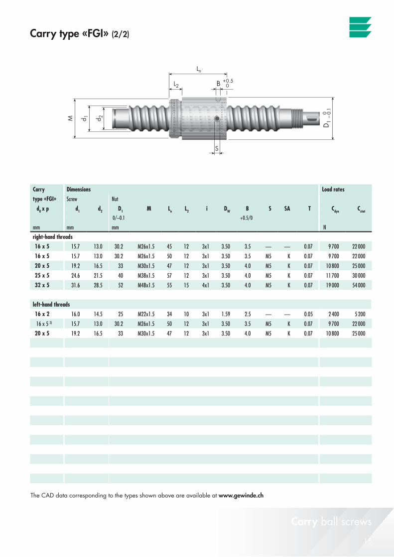
15© Eichenberger Gewinde AG – V 12 01 30
Carry
d0 x p d1 d2 D1 M Ln L2 i DW B S SA T0/–0.1 +0.5/0
mm mm mm N
16 x 5 15.7 13.0 30.2 M26x1.5 45 12 3x1 3.50 3.5 — — 0.07 9 700 22 000
16 x 5 15.7 13.0 30.2 M26x1.5 50 12 3x1 3.50 3.5 M5 K 0.07 9 700 22 000
20 x 5 19.2 16.5 33 M30x1.5 47 12 3x1 3.50 4.0 M5 K 0.07 10 800 25 000
25 x 5 24.6 21.5 40 M38x1.5 57 12 3x1 3.50 4.0 M5 K 0.07 11 700 30 000
32 x 5 31.6 28.5 52 M48x1.5 55 15 4x1 3.50 4.0 M5 K 0.07 19 000 54 000
16 x 2 16.0 14.5 25 M22x1.5 34 10 3x1 1.59 2.5 — — 0.05 2 400 5 200
16 x 5 3) 15.7 13.0 30.2 M26x1.5 50 12 3x1 3.50 3.5 M5 K 0.07 9 700 22 000
20 x 5 19.2 16.5 33 M30x1.5 47 12 3x1 3.50 4.0 M5 K 0.07 10 800 25 000
Carry ball screws
The CAD data corresponding to the types shown above are available at www.gewinde.ch
Carry type «FGI» (2/2)
Dimensions Load rates
type «FGI» Screw Nut
Cdyn Cstat
right-hand threads
left-hand threads

16 © Eichenberger Gewinde AG – V 12 01 30
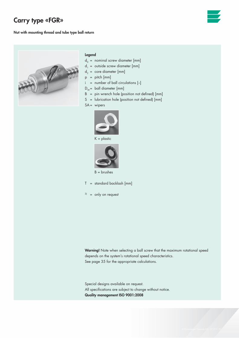
Carry type «FGR»
Nut with mounting thread and tube type ball return
Legendd0 = nominal screw diameter [mm]d1 = outside screw diameter [mm]d2 = core diameter [mm]p = pitch [mm]i = number of ball circulations [–]DW = ball diameter [mm]B = pin wrench hole (position not defined) [mm]S = lubrication hole (position not defined) [mm]SA = wipers
K = plastic
B = brushes
T = standard backlash [mm]
3) = only on request
Warning! Note when selecting a ball screw that the maximum rotational speed depends on the system’s rotational speed characteristics.See page 35 for the appropriate calculations.
Special designs available on request. All specifications are subject to change without notice.Quality management ISO 9001:2008
Carry ball screws
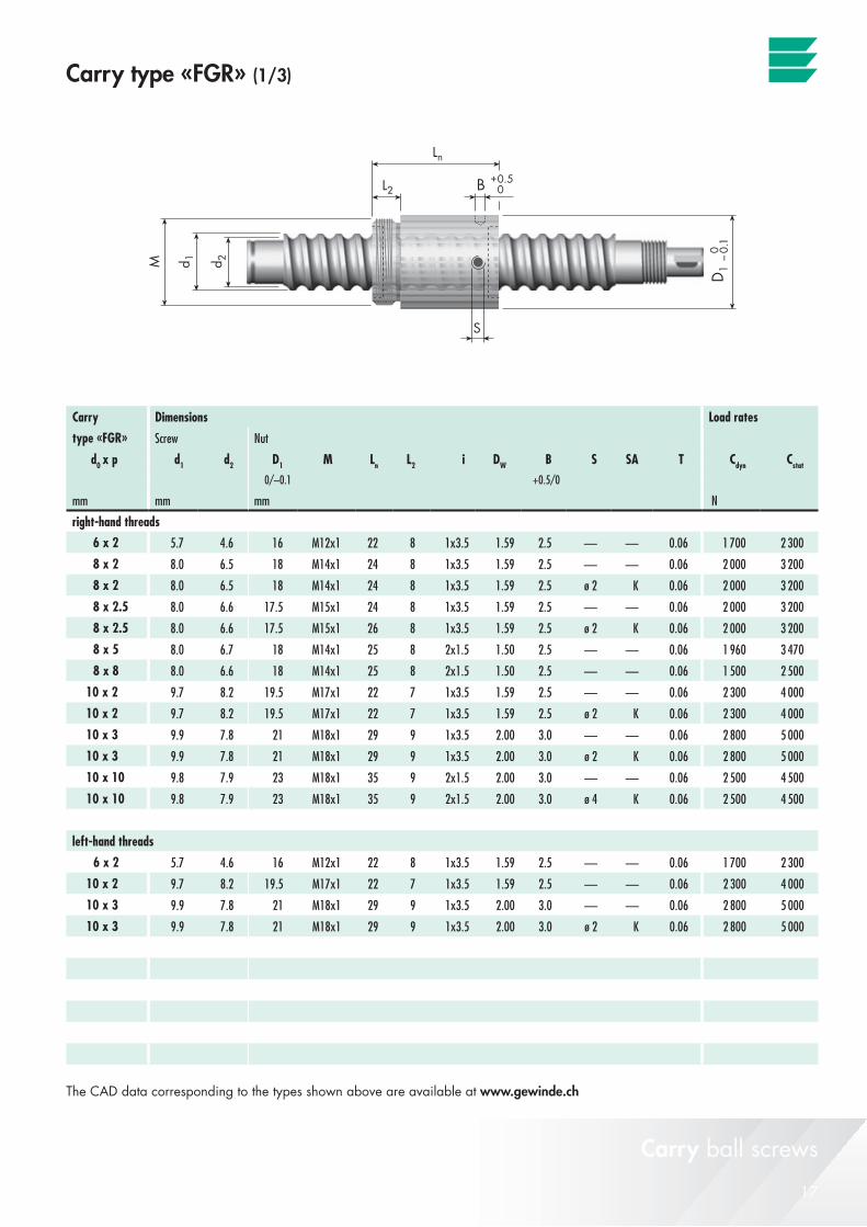
17© Eichenberger Gewinde AG – V 12 01 30
Carry
d0 x p d1 d2 D1 M Ln L2 i DW B S SA T 0/–0.1 +0.5/0
mm mm mm N
6 x 2 5.7 4.6 16 M12x1 22 8 1x3.5 1.59 2.5 — — 0.06 1 700 2 300
8 x 2 8.0 6.5 18 M14x1 24 8 1x3.5 1.59 2.5 — — 0.06 2 000 3 200
8 x 2 8.0 6.5 18 M14x1 24 8 1x3.5 1.59 2.5 ø 2 K 0.06 2 000 3 200
8 x 2.5 8.0 6.6 17.5 M15x1 24 8 1x3.5 1.59 2.5 — — 0.06 2 000 3 200
8 x 2.5 8.0 6.6 17.5 M15x1 26 8 1x3.5 1.59 2.5 ø 2 K 0.06 2 000 3 200
8 x 5 8.0 6.7 18 M14x1 25 8 2x1.5 1.50 2.5 — — 0.06 1 960 3 470
8 x 8 8.0 6.6 18 M14x1 25 8 2x1.5 1.50 2.5 — — 0.06 1 500 2 500
10 x 2 9.7 8.2 19.5 M17x1 22 7 1x3.5 1.59 2.5 — — 0.06 2 300 4 000
10 x 2 9.7 8.2 19.5 M17x1 22 7 1x3.5 1.59 2.5 ø 2 K 0.06 2 300 4 000
10 x 3 9.9 7.8 21 M18x1 29 9 1x3.5 2.00 3.0 — — 0.06 2 800 5 000
10 x 3 9.9 7.8 21 M18x1 29 9 1x3.5 2.00 3.0 ø 2 K 0.06 2 800 5 000
10 x 10 9.8 7.9 23 M18x1 35 9 2x1.5 2.00 3.0 — — 0.06 2 500 4 500
10 x 10 9.8 7.9 23 M18x1 35 9 2x1.5 2.00 3.0 ø 4 K 0.06 2 500 4 500
6 x 2 5.7 4.6 16 M12x1 22 8 1x3.5 1.59 2.5 — — 0.06 1 700 2 300
10 x 2 9.7 8.2 19.5 M17x1 22 7 1x3.5 1.59 2.5 — — 0.06 2 300 4 000
10 x 3 9.9 7.8 21 M18x1 29 9 1x3.5 2.00 3.0 — — 0.06 2 800 5 000
10 x 3 9.9 7.8 21 M18x1 29 9 1x3.5 2.00 3.0 ø 2 K 0.06 2 800 5 000
Carry type «FGR» (1/3)
Carry ball screws
The CAD data corresponding to the types shown above are available at www.gewinde.ch
Dimensions Load rates
type «FGR» Screw Nut
Cdyn Cstat
right-hand threads
left-hand threads

18 © Eichenberger Gewinde AG – V 12 01 30
Carry type «FGR»
N ut with mounting thread and tube type ball return
Legendd0 = nominal screw diameter [mm]d1 = outside screw diameter [mm]d2 = core diameter [mm]p = pitch [mm]i = number of ball circulations [–]DW = ball diameter [mm]B = pin wrench hole (position not defined) [mm]S = lubrication hole (position not defined) [mm]SA = wipers
K = plastic
B = brushes
T = standard backlash [mm]
3) = only on request
Warning! Note when selecting a ball screw that the maximum rotational speed depends on the system’s rotational speed characteristics.See page 35 for the appropriate calculations.
Special designs available on request. All specifications are subject to change without notice.Quality management ISO 9001:2008
Carry ball screws
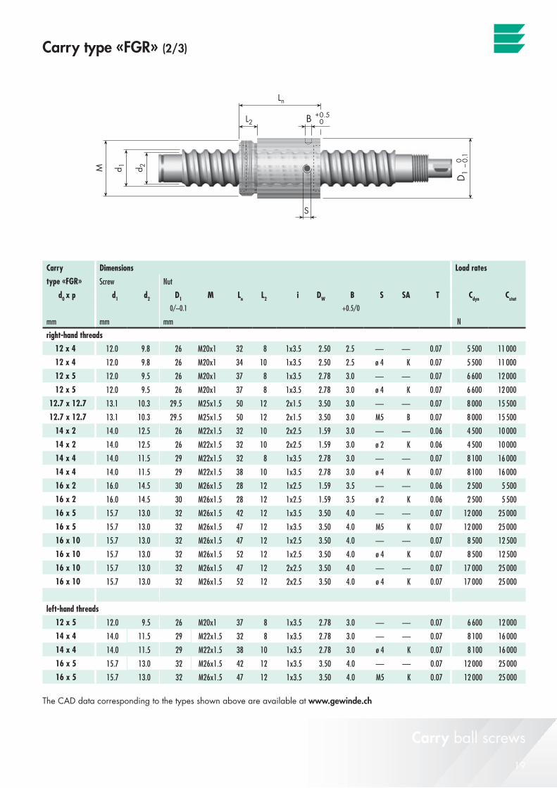
19© Eichenberger Gewinde AG – V 12 01 30
Carry
d0 x p d1 d2 D1 M Ln L2 i DW B S SA T 0/–0.1 +0.5/0
mm mm mm N
12 x 4 12.0 9.8 26 M20x1 32 8 1x3.5 2.50 2.5 — — 0.07 5 500 11 000
12 x 4 12.0 9.8 26 M20x1 34 10 1x3.5 2.50 2.5 ø 4 K 0.07 5 500 11 000
12 x 5 12.0 9.5 26 M20x1 37 8 1x3.5 2.78 3.0 — — 0.07 6 600 12 000
12 x 5 12.0 9.5 26 M20x1 37 8 1x3.5 2.78 3.0 ø 4 K 0.07 6 600 12 000
12.7 x 12.7 13.1 10.3 29.5 M25x1.5 50 12 2x1.5 3.50 3.0 — — 0.07 8 000 15 500
12.7 x 12.7 13.1 10.3 29.5 M25x1.5 50 12 2x1.5 3.50 3.0 M5 B 0.07 8 000 15 500
14 x 2 14.0 12.5 26 M22x1.5 32 10 2x2.5 1.59 3.0 — — 0.06 4 500 10 000
14 x 2 14.0 12.5 26 M22x1.5 32 10 2x2.5 1.59 3.0 ø 2 K 0.06 4 500 10 000
14 x 4 14.0 11.5 29 M22x1.5 32 8 1x3.5 2.78 3.0 — — 0.07 8 100 16 000
14 x 4 14.0 11.5 29 M22x1.5 38 10 1x3.5 2.78 3.0 ø 4 K 0.07 8 100 16 000
16 x 2 16.0 14.5 30 M26x1.5 28 12 1x2.5 1.59 3.5 — — 0.06 2 500 5 500
16 x 2 16.0 14.5 30 M26x1.5 28 12 1x2.5 1.59 3.5 ø 2 K 0.06 2 500 5 500
16 x 5 15.7 13.0 32 M26x1.5 42 12 1x3.5 3.50 4.0 — — 0.07 12 000 25 000
16 x 5 15.7 13.0 32 M26x1.5 47 12 1x3.5 3.50 4.0 M5 K 0.07 12 000 25 000
16 x 10 15.7 13.0 32 M26x1.5 47 12 1x2.5 3.50 4.0 — — 0.07 8 500 12 500
16 x 10 15.7 13.0 32 M26x1.5 52 12 1x2.5 3.50 4.0 ø 4 K 0.07 8 500 12 500
16 x 10 15.7 13.0 32 M26x1.5 47 12 2x2.5 3.50 4.0 — — 0.07 17 000 25 000
16 x 10 15.7 13.0 32 M26x1.5 52 12 2x2.5 3.50 4.0 ø 4 K 0.07 17 000 25 000
12 x 5 12.0 9.5 26 M20x1 37 8 1x3.5 2.78 3.0 — — 0.07 6 600 12 000
14 x 4 14.0 11.5 29 M22x1.5 32 8 1x3.5 2.78 3.0 — — 0.07 8 100 16 000
14 x 4 14.0 11.5 29 M22x1.5 38 10 1x3.5 2.78 3.0 ø 4 K 0.07 8 100 16 000
16 x 5 15.7 13.0 32 M26x1.5 42 12 1x3.5 3.50 4.0 — — 0.07 12 000 25 000
16 x 5 15.7 13.0 32 M26x1.5 47 12 1x3.5 3.50 4.0 M5 K 0.07 12 000 25 000
Carry type «FGR» (2/3)
Carry ball screws
The CAD data corresponding to the types shown above are available at www.gewinde.ch
Dimensions Load rates
type «FGR» Screw Nut
Cdyn Cstat
right-hand threads
left-hand threads
20 © Eichenberger Gewinde AG – V 12 01 30
Carry type «FGR»
N ut with mounting thread and tube type ball return
Legendd0 = nominal screw diameter [mm]d1 = outside screw diameter [mm]d2 = core diameter [mm]p = pitch [mm]i = number of ball circulations [–]DW = ball diameter [mm]B = pin wrench hole (position not defined) [mm]S = lubrication hole (position not defined) [mm]SA = wipers
K = plastic
B = brushes
T = standard backlash [mm]
3) = only on request
Warning! Note when selecting a ball screw that the maximum rotational speed depends on the system’s rotational speed characteristics.See page 35 for the appropriate calculations.
Special designs available on request. All specifications are subject to change without notice.Quality management ISO 9001:2008
Carry ball screws
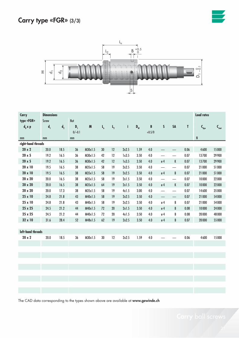
21© Eichenberger Gewinde AG – V 12 01 30
Carry
d0 x p d1 d2 D1 M Ln L2 i DW B S SA T 0/–0.1 +0.5/0
mm mm mm N
20 x 2 20.0 18.5 36 M30x1.5 30 12 2x2.5 1.59 4.0 — — 0.06 4 600 15 000
20 x 5 19.2 16.5 36 M30x1.5 42 12 1x3.5 3.50 4.0 — — 0.07 13 700 29 900
20 x 5 19.2 16.5 36 M30x1.5 42 12 1x3.5 3.50 4.0 ø 4 K 0.07 13 700 29 900
20 x 10 19.5 16.5 38 M35x1.5 58 19 2x2.5 3.50 4.0 — — 0.07 21 000 51 000
20 x 10 19.5 16.5 38 M35x1.5 58 19 2x2.5 3.50 4.0 ø 4 B 0.07 21 000 51 000
20 x 20 20.0 16.5 38 M35x1.5 58 19 2x1.5 3.50 4.0 — — 0.07 10 000 22 000
20 x 20 20.0 16.5 38 M35x1.5 64 19 2x1.5 3.50 4.0 ø 4 K 0.07 10 000 22 000
20 x 20 20.0 17.3 38 M35x1.5 58 19 4x1.5 3.00 4.0 — — 0.07 14 600 35 000
25 x 10 24.8 21.8 43 M40x1.5 58 19 2x2.5 3.50 4.0 — — 0.07 21 000 54 000
25 x 10 24.8 21.8 43 M40x1.5 58 19 2x2.5 3.50 4.0 ø 4 B 0.07 21 000 54 000
25 x 25 24.5 21.2 44 M40x1.5 72 20 2x1.5 3.50 4.0 ø 4 B 0.08 10 000 24 000
25 x 25 24.5 21.2 44 M40x1.5 72 20 4x1.5 3.50 4.0 ø 4 B 0.08 20 000 48 000
32 x 10 31.6 28.4 52 M48x1.5 62 19 2x2.5 3.50 4.0 ø 4 B 0.07 20 000 55 000
20 x 2 20.0 18.5 36 M30x1.5 30 12 2x2.5 1.59 4.0 — — 0.06 4 600 15 000
Carry type «FGR» (3/3)
Carry ball screws
The CAD data corresponding to the types shown above are available at www.gewinde.ch
Dimensions Load rates
type «FGR» Screw Nut
Cdyn Cstat
right-hand threads
left-hand threads
22 © Eichenberger Gewinde AG – V 12 01 30
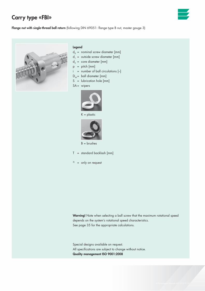
Carry type «FBI»
Flange nut with single-thread ball return (following DIN 69051: flange type B nut, master gauge 3)
Legendd0 = nominal screw diameter [mm]d1 = outside screw diameter [mm]d2 = core diameter [mm]p = pitch [mm]i = number of ball circulations [–]DW = ball diameter [mm]S = lubrication hole [mm]SA = wipers
K = plastic
B = brushes
T = standard backlash [mm]
3) = only on request
Warning! Note when selecting a ball screw that the maximum rotational speed depends on the system’s rotational speed characteristics.See page 35 for the appropriate calculations.
Special designs available on request. All specifications are subject to change without notice.Quality management ISO 9001:2008
Carry ball screws
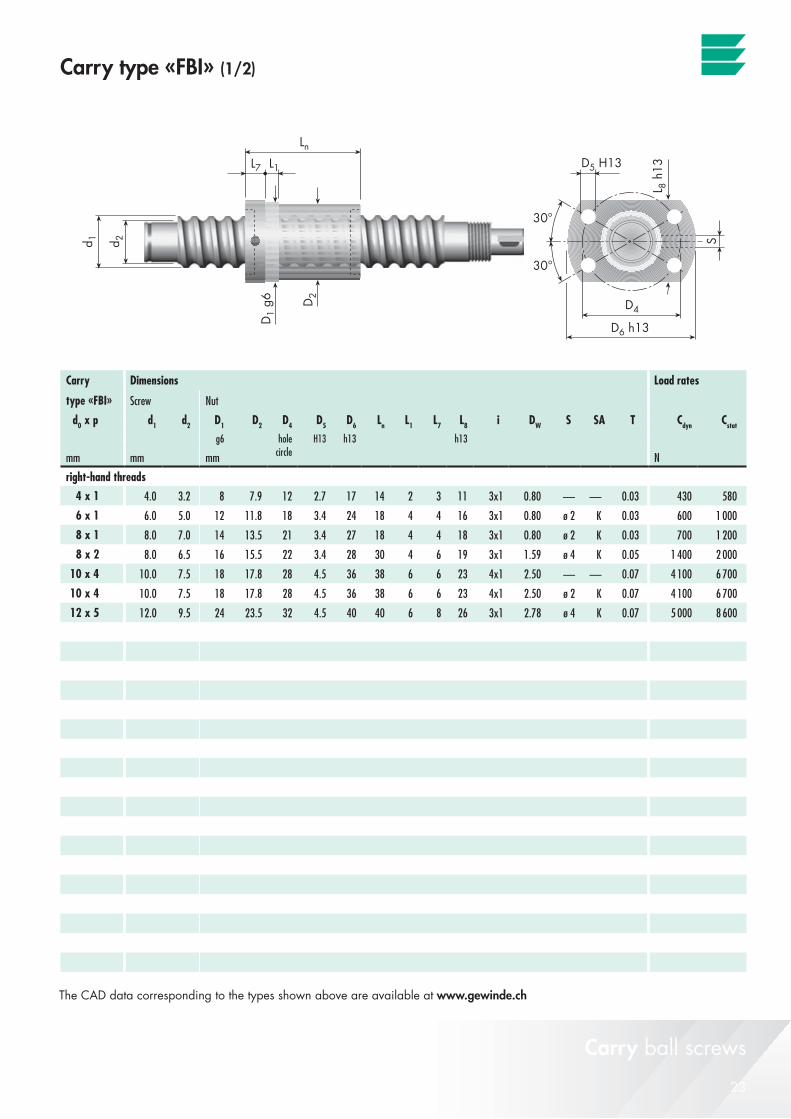
23© Eichenberger Gewinde AG – V 12 01 30
Carry
d0 x p d1 d2 D1 D2 D4 D5 D6 Ln L1 L7 L8 i DW S SA Tg6 H13 h13 h13
mm mm mm N
4 x 1 4.0 3.2 8 7.9 12 2.7 17 14 2 3 11 3x1 0.80 — — 0.03 430 580
6 x 1 6.0 5.0 12 11.8 18 3.4 24 18 4 4 16 3x1 0.80 ø 2 K 0.03 600 1 000
8 x 1 8.0 7.0 14 13.5 21 3.4 27 18 4 4 18 3x1 0.80 ø 2 K 0.03 700 1 200
8 x 2 8.0 6.5 16 15.5 22 3.4 28 30 4 6 19 3x1 1.59 ø 4 K 0.05 1 400 2 000
10 x 4 10.0 7.5 18 17.8 28 4.5 36 38 6 6 23 4x1 2.50 — — 0.07 4 100 6 700
10 x 4 10.0 7.5 18 17.8 28 4.5 36 38 6 6 23 4x1 2.50 ø 2 K 0.07 4 100 6 700
12 x 5 12.0 9.5 24 23.5 32 4.5 40 40 6 8 26 3x1 2.78 ø 4 K 0.07 5 000 8 600
Carry type «FBI» (1/2)
Carry ball screws
The CAD data corresponding to the types shown above are available at www.gewinde.ch
Dimensions Load rates
type «FBI» Screw Nut
Cdyn Cstat
holecircle
right-hand threads

24 © Eichenberger Gewinde AG – V 12 01 30
Carry type «FBI»
Flange nut with single-thread ball return (following DIN 69051: flange type B nut, master gauge 1)
Legendd0 = nominal screw diameter [mm]d1 = outside screw diameter [mm]d2 = core diameter [mm]p = pitch [mm]i = number of ball circulations [–]DW = ball diameter [mm]S = lubrication hole [mm]SA = wipers
K = plastic
B = brushes
T = standard backlash [mm]
3) = only on request
Warning! Note when selecting a ball screw that the maximum rotational speed depends on the system’s rotational speed characteristics.See page 35 for the appropriate calculations.
Special designs available on request. All specifications are subject to change without notice.Quality management ISO 9001:2008
Carry ball screws
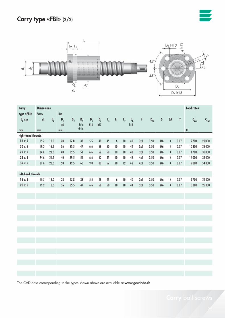
25© Eichenberger Gewinde AG – V 12 01 30
Carry
d0 x p d1 d2 D1 D2 D4 D5 D6 Ln L1 L7 L8 i DW S SA Tg6 H13 h13 h13
mm mm mm N
16 x 5 15.7 13.0 28 27.8 38 5.5 48 45 6 10 40 3x1 3.50 M6 K 0.07 9 700 22 000
20 x 5 19.2 16.5 36 35.5 47 6.6 58 50 10 10 44 3x1 3.50 M6 K 0.07 10 800 25 000
25 x 5 24.6 21.5 40 39.5 51 6.6 62 50 10 10 48 3x1 3.50 M6 K 0.07 11 700 30 000
25 x 5 24.6 21.5 40 39.5 51 6.6 62 55 10 10 48 4x1 3.50 M6 K 0.07 14 000 35 000
32 x 5 31.6 28.5 50 49.5 65 9.0 80 57 10 12 62 4x1 3.50 M6 K 0.07 19 000 54 000
16 x 5 15.7 13.0 28 27.8 38 5.5 48 45 6 10 40 3x1 3.50 M6 K 0.07 9 700 22 000
20 x 5 19.2 16.5 36 35.5 47 6.6 58 50 10 10 44 3x1 3.50 M6 K 0.07 10 800 25 000
Carry type «FBI» (2/2)
Carry ball screws
The CAD data corresponding to the types shown above are available at www.gewinde.ch
Dimensions Load rates
type «FBI» Screw Nut
Cdyn Cstat
holecircle
right-hand threads
left-hand threads

26 © Eichenberger Gewinde AG – V 12 01 30
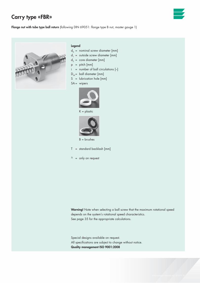
Carry type «FBR»
Flange nut with tube type ball return (following DIN 69051: flange type B nut, master gauge 3)
Legendd0 = nominal screw diameter [mm]d1 = outside screw diameter [mm]d2 = core diameter [mm]p = pitch [mm]i = number of ball circulations [–]DW = ball diameter [mm]S = lubrication hole [mm]SA = wipers
K = plastic
B = brushes
T = standard backlash [mm]
3) = only on request
Warning! Note when selecting a ball screw that the maximum rotational speed depends on the system’s rotational speed characteristics.See page 35 for the appropriate calculations.
Special designs available on request. All specifications are subject to change without notice.Quality management ISO 9001:2008
Carry ball screws
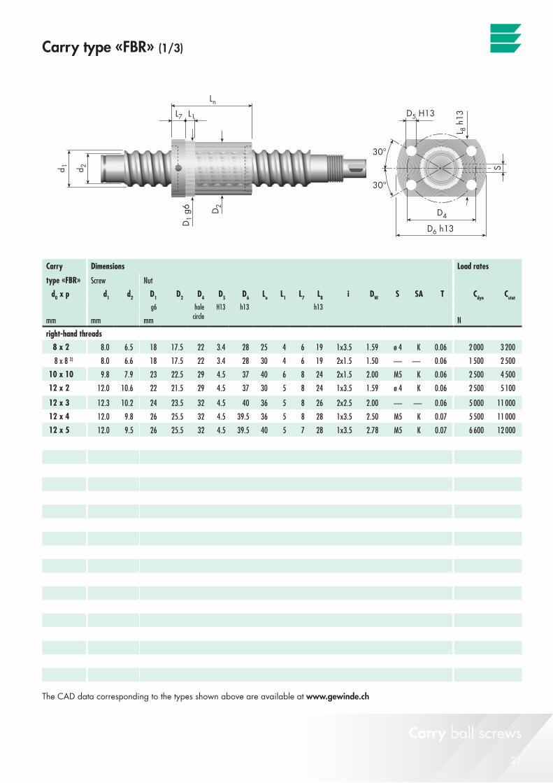
27© Eichenberger Gewinde AG – V 12 01 30
Carry
d0 x p d1 d2 D1 D2 D4 D5 D6 Ln L1 L7 L8 i DW S SA Tg6 H13 h13 h13
mm mm mm N
8 x 2 8.0 6.5 18 17.5 22 3.4 28 25 4 6 19 1x3.5 1.59 ø 4 K 0.06 2 000 3 200
8 x 8 3) 8.0 6.6 18 17.5 22 3.4 28 30 4 6 19 2x1.5 1.50 — — 0.06 1 500 2 500
10 x 10 9.8 7.9 23 22.5 29 4.5 37 40 6 8 24 2x1.5 2.00 M5 K 0.06 2 500 4 500
12 x 2 12.0 10.6 22 21.5 29 4.5 37 30 5 8 24 1x3.5 1.59 ø 4 K 0.06 2 500 5 100
12 x 3 12.3 10.2 24 23.5 32 4.5 40 36 5 8 26 2x2.5 2.00 — — 0.06 5 000 11 000
12 x 4 12.0 9.8 26 25.5 32 4.5 39.5 36 5 8 28 1x3.5 2.50 M5 K 0.07 5 500 11 000
12 x 5 12.0 9.5 26 25.5 32 4.5 39.5 40 5 7 28 1x3.5 2.78 M5 K 0.07 6 600 12 000
Carry type «FBR» (1/3)
Carry ball screws
The CAD data corresponding to the types shown above are available at www.gewinde.ch
Dimensions Load rates
type «FBR» Screw Nut
Cdyn Cstat
holecircle
right-hand threads
28 © Eichenberger Gewinde AG – V 12 01 30
Carry type «FBR»
Flange nut with tube type ball return (following DIN 69051: flange type B nut, master gauge 1)
Legendd0 = nominal screw diameter [mm]d1 = outside screw diameter [mm]d2 = core diameter [mm]p = pitch [mm]i = number of ball circulations [–]DW = ball diameter [mm]S = lubrication hole [mm]SA = wipers
K = plastic
B = brushes
T = standard backlash [mm]
3) = only on request
Warning! Note when selecting a ball screw that the maximum rotational speed depends on the system’s rotational speed characteristics.See page 35 for the appropriate calculations.
Special designs available on request. All specifications are subject to change without notice.Quality management ISO 9001:2008
Carry ball screws
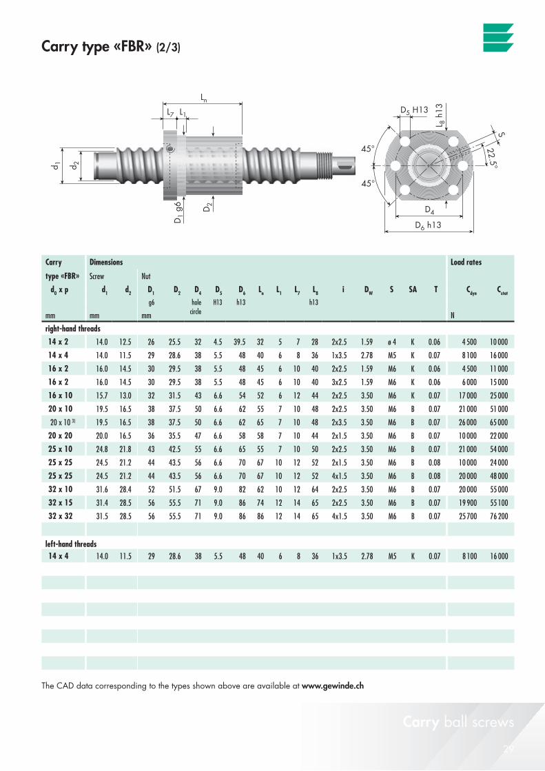
29© Eichenberger Gewinde AG – V 12 01 30
Carry
d0 x p d1 d2 D1 D2 D4 D5 D6 Ln L1 L7 L8 i DW S SA Tg6 H13 h13 h13
mm mm mm N
14 x 2 14.0 12.5 26 25.5 32 4.5 39.5 32 5 7 28 2x2.5 1.59 ø 4 K 0.06 4 500 10 000
14 x 4 14.0 11.5 29 28.6 38 5.5 48 40 6 8 36 1x3.5 2.78 M5 K 0.07 8 100 16 000
16 x 2 16.0 14.5 30 29.5 38 5.5 48 45 6 10 40 2x2.5 1.59 M6 K 0.06 4 500 11 000
16 x 2 16.0 14.5 30 29.5 38 5.5 48 45 6 10 40 3x2.5 1.59 M6 K 0.06 6 000 15 000
16 x 10 15.7 13.0 32 31.5 43 6.6 54 52 6 12 44 2x2.5 3.50 M6 K 0.07 17 000 25 000
20 x 10 19.5 16.5 38 37.5 50 6.6 62 55 7 10 48 2x2.5 3.50 M6 B 0.07 21 000 51 000
20 x 10 3) 19.5 16.5 38 37.5 50 6.6 62 65 7 10 48 2x3.5 3.50 M6 B 0.07 26 000 65 000
20 x 20 20.0 16.5 36 35.5 47 6.6 58 58 7 10 44 2x1.5 3.50 M6 B 0.07 10 000 22 000
25 x 10 24.8 21.8 43 42.5 55 6.6 65 55 7 10 50 2x2.5 3.50 M6 B 0.07 21 000 54 000
25 x 25 24.5 21.2 44 43.5 56 6.6 70 67 10 12 52 2x1.5 3.50 M6 B 0.08 10 000 24 000
25 x 25 24.5 21.2 44 43.5 56 6.6 70 67 10 12 52 4x1.5 3.50 M6 B 0.08 20 000 48 000
32 x 10 31.6 28.4 52 51.5 67 9.0 82 62 10 12 64 2x2.5 3.50 M6 B 0.07 20 000 55 000
32 x 15 31.4 28.5 56 55.5 71 9.0 86 74 12 14 65 2x2.5 3.50 M6 B 0.07 19 900 55 100
32 x 32 31.5 28.5 56 55.5 71 9.0 86 86 12 14 65 4x1.5 3.50 M6 B 0.07 25 700 76 200
14 x 4 14.0 11.5 29 28.6 38 5.5 48 40 6 8 36 1x3.5 2.78 M5 K 0.07 8 100 16 000
Carry type «FBR» (2/3)
Carry ball screws
The CAD data corresponding to the types shown above are available at www.gewinde.ch
Dimensions Load rates
type «FBR» Screw Nut
Cdyn Cstat
holecircle
right-hand threads
left-hand threads

30 © Eichenberger Gewinde AG – V 12 01 30
Carry type «FBR»
Flange nut with tube type ball return (following DIN 69051: flange type B nut, master gauge 2)
Legendd0 = nominal screw diameter [mm]d1 = outside screw diameter [mm]d2 = core diameter [mm]p = pitch [mm]i = number of ball circulations [–]DW = ball diameter [mm]S = lubrication hole [mm]SA = wipers
K = plastic
B = brushes
T = standard backlash [mm]
3) = only on request
Warning! Note when selecting a ball screw that the maximum rotational speed depends on the system’s rotational speed characteristics.See page 35 for the appropriate calculations.
Special designs available on request. All specifications are subject to change without notice.Quality management ISO 9001:2008
Carry ball screws
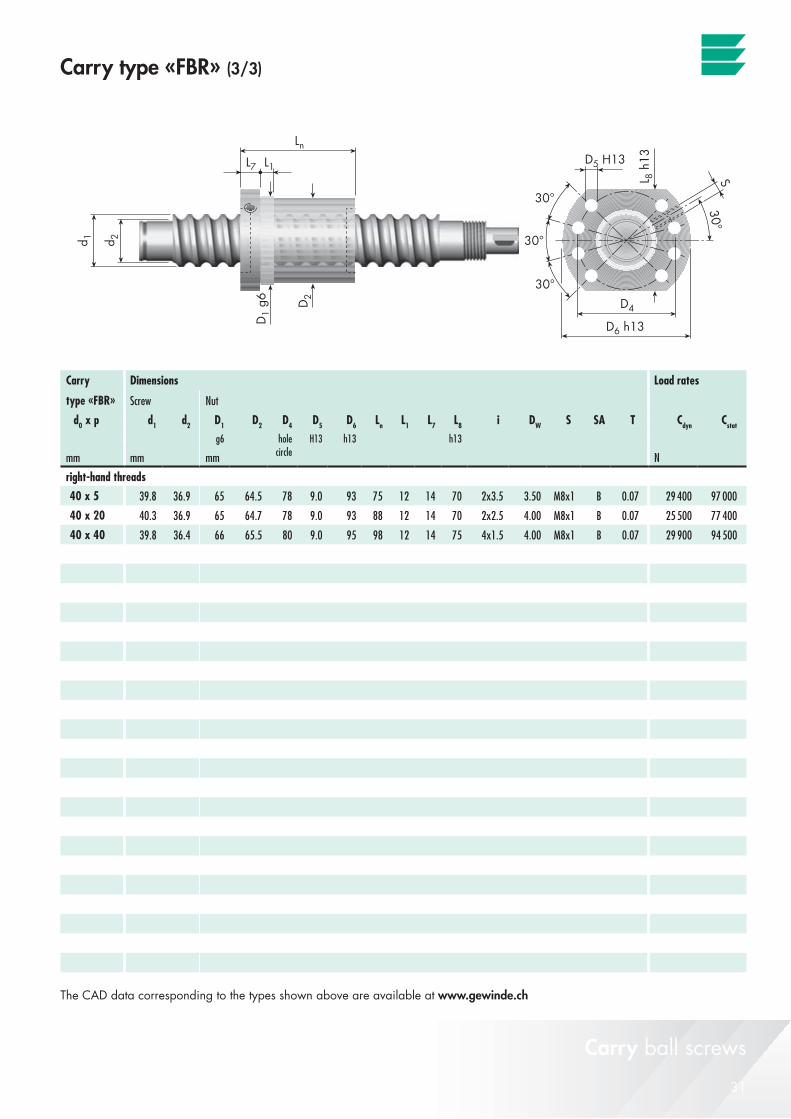
31© Eichenberger Gewinde AG – V 12 01 30
Carry
d0 x p d1 d2 D1 D2 D4 D5 D6 Ln L1 L7 L8 i DW S SA Tg6 H13 h13 h13
mm mm mm N
40 x 5 39.8 36.9 65 64.5 78 9.0 93 75 12 14 70 2x3.5 3.50 M8x1 B 0.07 29 400 97 000
40 x 20 40.3 36.9 65 64.7 78 9.0 93 88 12 14 70 2x2.5 4.00 M8x1 B 0.07 25 500 77 400
40 x 40 39.8 36.4 66 65.5 80 9.0 95 98 12 14 75 4x1.5 4.00 M8x1 B 0.07 29 900 94 500
Carry type «FBR» (3/3)
Carry ball screws
The CAD data corresponding to the types shown above are available at www.gewinde.ch
Dimensions Load rates
type «FBR» Screw Nut
Cdyn Cstat
holecircle
right-hand threads
32 © Eichenberger Gewinde AG – V 12 01 30
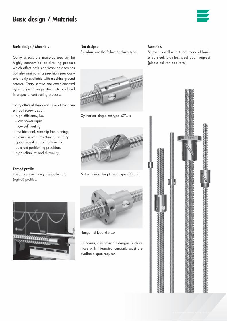
Nut designsStandard are the following three types:
Cylindrical single nut type «ZY…»
Nut with mounting thread type «FG…»
Flange nut type «FB…»
Of course, any other nut designs (such as those with integrated cardanic axis) are available upon request.
Basic design / Materials
Basic design / Materials
Carry screws are manufactured by the highly economical cold-rolling process which offers both significant cost savings but also maintains a precision previously often only available with machine-ground screws. Carry screws are complemented by a range of single steel nuts produced in a special cost-cutting process.
Carry offers all the advantages of the inher-ent ball screw design:– high efficiency, i.e. - low power input - low self-heating– low frictional, stick-slip-free running– maximum wear resistance, i.e. very good repetition accuracy with a constant positioning precision.– high reliability and durability.
Thread profileUsed most commonly are gothic arc (ogival) profiles.
MaterialsScrews as well as nuts are made of hard-ened steel. Stainless steel upon request (please ask for load rates).
Carry ball screws
33© Eichenberger Gewinde AG – V 12 01 30
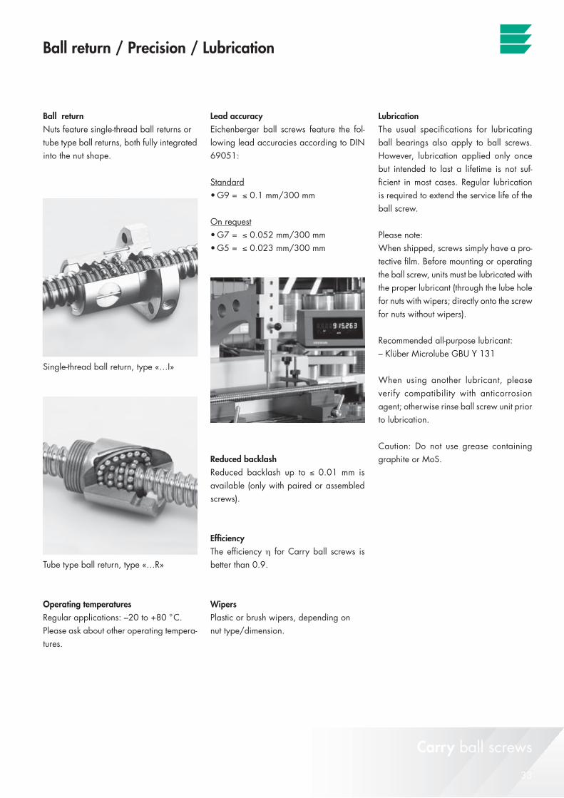
Ball return / Precision / Lubrication
Ball returnNuts feature single-thread ball returns or tube type ball returns, both fully integrated into the nut shape.
Single-thread ball return, type «…I»
Tube type ball return, type «…R»
Operating temperaturesRegular applications: –20 to +80 °C. Please ask about other operating tempera-tures.
Lead accuracyEichenberger ball screws feature the fol-lowing lead accuracies according to DIN 69051:
Standard•G9=≤ 0.1 mm/300 mm
On request•G7=≤ 0.052 mm/300 mm •G5=≤ 0.023 mm/300 mm
Reduced backlashReduced backlash up to ≤ 0.01 mm is available (only with paired or assembled screws).
EfficiencyThe efficiency η for Carry ball screws is better than 0.9.
WipersPlastic or brush wipers, depending on nut type/dimension.
LubricationThe usual specifications for lubricating ball bearings also apply to ball screws. However, lubrication applied only once but intended to last a lifetime is not suf-ficient in most cases. Regular lubrication is required to extend the service life of the ball screw.
Please note:When shipped, screws simply have a pro-tective film. Before mounting or operating the ball screw, units must be lubricated with the proper lubricant (through the lube hole for nuts with wipers; directly onto the screw for nuts without wipers).
Recommended all-purpose lubricant:– Klüber Microlube GBU Y 131
When using another lubricant, please verify compatibility with anticorrosion agent; otherwise rinse ball screw unit prior to lubrication.
Caution: Do not use grease containing graphite or MoS.
Carry ball screws
34 © Eichenberger Gewinde AG – V 12 01 30
Factory length / Ball screw ends / Handling
Factory lengthIn general, Eichenberger screws are available as threaded rods, approx. 2.8 to 3 m long. Upon request, lengths up to 6 m are available, depending on diameter and supply market situation.
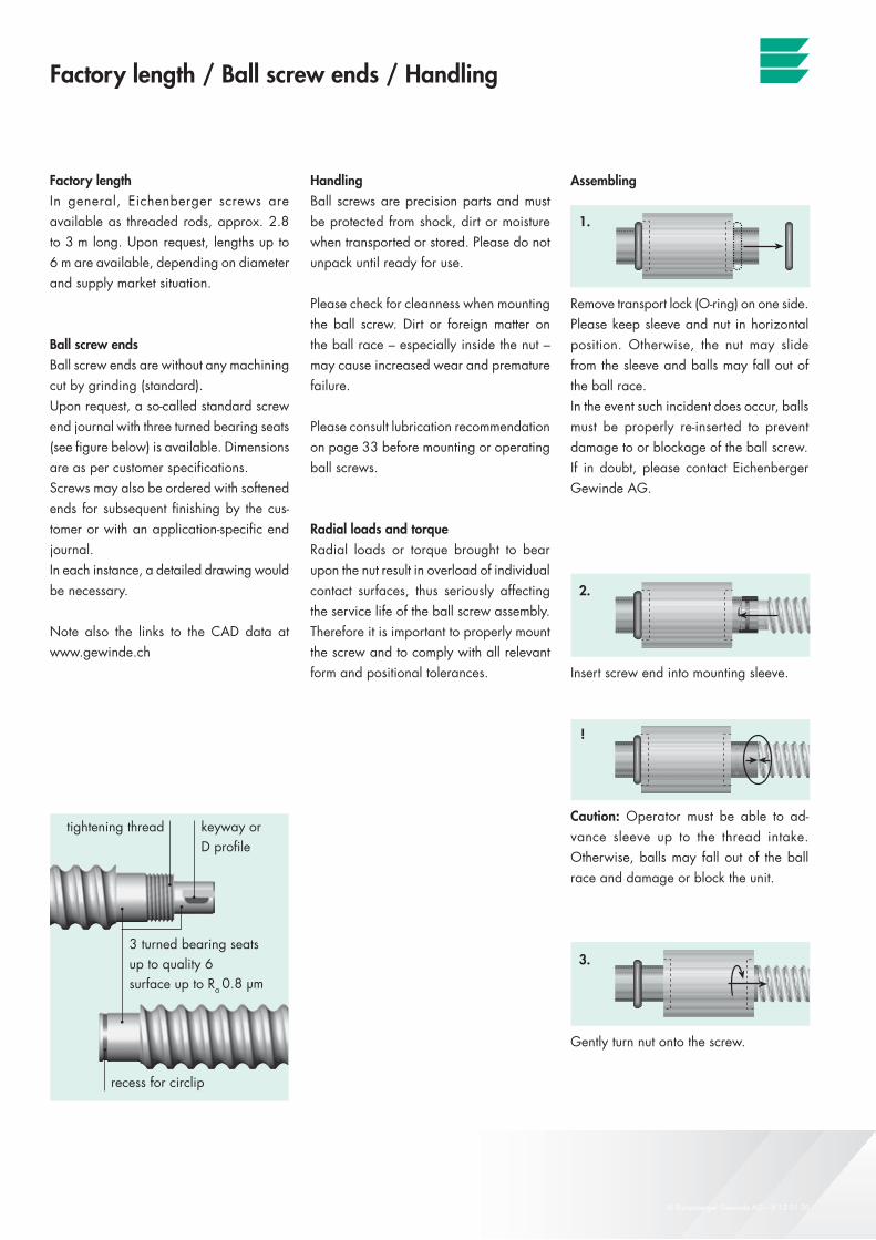
Ball screw endsBall screw ends are without any machining cut by grinding (standard). Upon request, a so-called standard screw end journal with three turned bearing seats (see figure below) is available. Dimensions are as per customer specifications. Screws may also be ordered with softened ends for subsequent finishing by the cus-tomer or with an application-specific end journal.In each instance, a detailed drawing would be necessary.
Note also the links to the CAD data at www.gewinde.ch
HandlingBall screws are precision parts and must be protected from shock, dirt or moisture when transported or stored. Please do not unpack until ready for use.
Please check for cleanness when mounting the ball screw. Dirt or foreign matter on the ball race – especially inside the nut – may cause increased wear and premature failure.
Please consult lubrication recommendation on page 33 before mounting or operating ball screws.
Radial loads and torqueRadial loads or torque brought to bear upon the nut result in overload of individual contact surfaces, thus seriously affecting the service life of the ball screw assembly. Therefore it is important to properly mount the screw and to comply with all relevant form and positional tolerances.
Assembling
1.
Remove transport lock (O-ring) on one side.Please keep sleeve and nut in horizontal position. Otherwise, the nut may slide from the sleeve and balls may fall out of the ball race.In the event such incident does occur, balls must be properly re-inserted to prevent damage to or blockage of the ball screw.If in doubt, please contact Eichenberger Gewinde AG.
2.
Insert screw end into mounting sleeve.
!
Caution: Operator must be able to ad-vance sleeve up to the thread intake. Otherwise, balls may fall out of the ball race and damage or block the unit.
3.
Gently turn nut onto the screw.
3 turned bearing seats up to quality 6surface up to Ra 0.8 µm
recess for circlip
tightening thread keyway orD profile
Carry ball screws
35© Eichenberger Gewinde AG – V 12 01 30
la
la
la
la
F [N]F1
F2
F3
q1 q2 q3 q4
F4
• q = 100 [%]
Fm
[%]
The following are the relevant calculations which underly screw design and safe operation.
For detailed information on ball screw design, please refer to DIN 69051.
«Suitability test» rotational speed characteristics
When selecting a ball screw it is important to first ensure that the correct nut design for the ball return system required to support the maximum rotational speed demanded by the application is used (independet of the screw length).
The maximum rotational speed is based on the system’s rotational speed characteristics and the outside screw diameter:
nmax = –––––––––––––––––––——– [min-1]
nmax = maximum rotational speed [min-1]
Rotational speed characteristics [–] for– single-thread ball return: 60 000 (Carry «…I» types)– tube type ball return: 80 000 (Carry «…R» types)– end cap ball return: 80 000 (Carry Speed-line «…E» types)
d1 = outside screw diameter [mm]
Design fundamentals
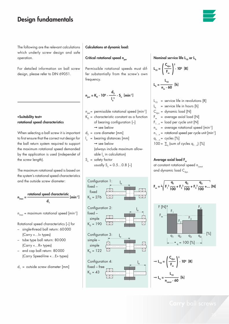
Calculations at dynamic load:
Critical rotational speed nper
Permissible rotational speeds must dif-fer substantially from the screw’s own frequency.
nper = KD · 106 · —— · Sn [min-1]
nper = permissible rotational speed [min-1]KD = characteristic constant as a function of bearing configuration [–] ➞ see belowd2 = core diameter [mm]la = bearing distances [mm] ➞ see below (always include maximum allow- able la in calculation)Sn = safety factor usually Sn = 0.5…0.8 [–]
Configuration 1: fixed – fixed KD = 276
Configuration 2: fixed – simple KD = 190
Configuration 3: simple – simple KD = 122
Configuration 4: fixed – free KD = 43
d2
la2
Nominal service life L10 or Lh
L10 = (––––)3
· 106 [R]
Lh = ––––––– [h]
L10 = service life in revolutions [R]Lh = service life in hours [h]Cdyn = dynamic load [N]Fm = average axial load [N]F1…n = load per cycle unit [N]nm = average rotational speed [min-1]n1…n = rotational speed per cycle unit [min-1]q1…n = cycles [%]100 = ∑q (sum of cycles q1…n) [%]
Average axial load Fm
at constant rotational speed nconst
and dynamic load Cdyn
Fm = 3 F13 ––– + F2
3 ––– + F33 ––– +… [N]
➞ L10 = (––––)3
· 106 [R]
➞ Lh = –––––––– [h]
Cdyn
Fm
L10
nm · 60
q1 q2 q3
100 100 100
Cdyn
Fm
L10
nconst · 60
Carry ball screws
rotational speed characteristic
d1
36 © Eichenberger Gewinde AG – V 12 01 30
n [min-1]n1
n2
n3
q1 q2 q3 q4
n4
• q = 100 [%]
nm
[%]
Design fundamentals
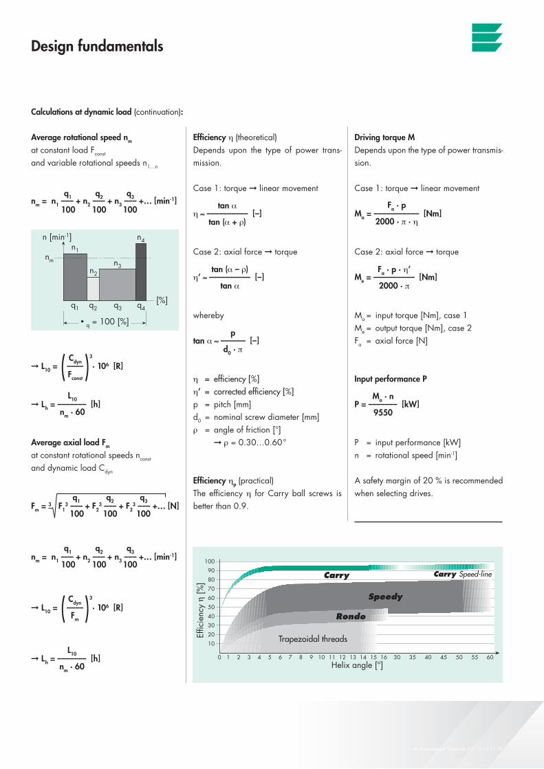
Driving torque MDepends upon the type of power transmis-sion.
Case 1: torque ➞ linear movement
Ma = ––––––––––– [Nm]
Case 2: axial force ➞ torque
Me = –––––––––– [Nm]
Ma = input torque [Nm], case 1Me = output torque [Nm], case 2Fa = axial force [N]
Input performance P
P = ––––––– [kW]
P = input performance [kW]n = rotational speed [min-1]
A safety margin of 20 % is recommended when selecting drives.
Fa · p
2000 · π · η
Ma · n
9550
Fa · p · η’
2000 · π
Average rotational speed nm
at constant load Fconst
and variable rotational speeds n1…n
nm = n1 ––– + n2 ––– + n3 ––– +… [min-1]
➞ L10 = (––––)3
· 106 [R]
➞ Lh = ––––––– [h]
Average axial load Fm
at constant rotational speeds nconst
and dynamic load Cdyn
Fm = 3 F13 ––– + F2
3 ––– + F33 ––– +… [N]
nm = n1 ––– + n2 ––– + n3 ––– +… [min-1]
➞ L10 = (––––)3
· 106 [R]
➞ Lh = ––––––– [h]
Cdyn
Fconst
L10
nm · 60
Cdyn
Fm
L10
nm · 60
Efficiency η (theoretical)Depends upon the type of power trans-mission.
Case 1: torque ➞ linear movement
η ≈ –––––––––– [–]
Case 2: axial force ➞ torque
η’ ≈ –––––––––– [–]
whereby
tan α ≈ –––––– [–]
η = efficiency [%]η’ = corrected efficiency [%]p = pitch [mm]d0 = nominal screw diameter [mm]ρ = angle of friction [°] ➞ ρ = 0.30…0.60°
Efficiency ηp (practical)The efficiency η for Carry ball screws is better than 0.9.
tan α
tan (α + ρ)
tan (α – ρ)
tan α
p
d0 · π
q1 q2 q3
100 100 100
q1 q2 q3
100 100 100
q1 q2 q3
100 100 100
Calculations at dynamic load (continuation):
Carry ball screws
37© Eichenberger Gewinde AG – V 12 01 30
la
la
la
la
Design fundamentals
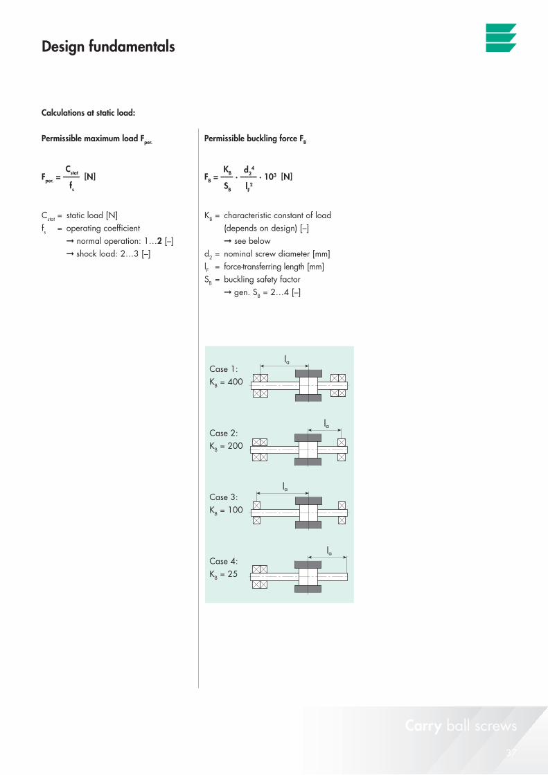
Calculations at static load:
Permissible maximum load Fper.
Fper. = —— [N]
Cstat = static load [N]fs = operating coefficient ➞ normal operation: 1…2 [–] ➞ shock load: 2…3 [–]
Permissible buckling force FB
FB = ––– · –––– · 103 [N]
KB = characteristic constant of load (depends on design) [–] ➞ see below d2 = nominal screw diameter [mm]lF = force-transferring length [mm]SB = buckling safety factor ➞ gen. SB = 2…4 [–]
Case 1: KB = 400
Case 2: KB = 200
Case 3: KB = 100
Case 4: KB = 25
KB
SB
d24
lF2
Cstat
fs
Carry ball screws
Beromünster
Menziken
�Basel
Aarau Lenzburg Zürich�
Reinach
LuzernBern
Beinwil a/See
Hallwilersee
Burg
Sursee
A2
A2
A1
A1
EichenbergerGewinde
Eichenberger Gewinde AGGrenzstrasse 30CH-5736 BurgSwitzerlandPhone +41 62 765 10 10Fax +41 62 765 10 [email protected]
When in Burg, follow the signs to Eichenberger Gewinde.
For detailed directions, please visit our website
www.gewinde.ch and click «Directions».
© Eichenberger Gewinde AG
The contents of this publication is protected by copyright held
by the publisher and may not be reproduced (even in part)
unless permission is granted. Every care has been taken to
ensure the accuracy of the information contained herein but
no liability shall be accepted for any loss or damage whether
direct, indirect or consequential resulting from or in connection
with the use of the information contained herein. This catalogue
supersedes previous catalogues in which the data deviate from
those contained herein. Data subject to change as required by
technological developments.
Edition: V 12 01 30 e