epg ~ final noise abatement policy and addendum - arizona
TRANSCRIPT

1 ADOT NAP Rev 2011-07-13
ARIZONA DEPARTMENT OF TRANSPORTATION
NOISE ABATEMENT POLICY
EFFECTIVE DATE: July 13, 2011
APPROVED BY: DATE: FLOYD ROEHRICH, State Engineer Arizona Department of Transportation
APPROVED BY: DATE: KARLA S. PETTY, Division Administrator
Federal Highway Administration
ARIZONA DEPARTMENT OF TRANSPORTATION ENVIRONMENTAL PLANNING GROUP
PHOENIX, ARIZONA
www.ADOTenvironmental.com 602-712-7767
Replaces Noise Abatement Policy issued 12/5/05, Amended 8/24/07.

2 ADOT NAP Rev 2011-07-13

3 ADOT NAP Rev 2011-07-13
TABLE OF CONTENTS 1. INTRODUCTION 2. APPLICABILITY 3. DEFINITIONS 4. ANALYSIS OF TRAFFIC NOISE
a. Selection of Design Year and Logical Termini b. Areas of Use and Receiver Placement c. Measurements of existing noise levels d. Traffic Noise Prediction e. Use of Noise Contour Lines f. Activity Categories g. Noise Impact Threshold
5. NOISE ABATEMENT CRITERIA TABLE 6. ANALYSIS OF NOISE ABATEMENT MEASURES
a. Line-of-Sight b. Prohibited Abatement Measures
7. FEASIBILITY a. Engineering Feasibility b. Acoustic Feasibility
8. REASONABLENESS a. Preferences of Property Owners and Residents b. Noise Reduction Design Goal c. Cost Effectiveness
1. Third Party Funding 9. INVENTORY AND REPORTING OF ABATEMENT MEASURES 10. INTERACTION WITH LOCAL JURISDICTIONS
a. Consultation with Local Jurisdictions b. Use of Local Jurisdiction Noise Abatement Policies on FHWA Projects c. Noise Compatible Land Use Planning
11. FEDERAL PARTICIPATION 12. CONSTRUCTION NOISE
Appendices
Appendix A: 23 CFR 772 Appendix B: Highway Traffic Noise Analysis and Abatement Guidance Revised January 2011 Appendix C: FHWA Report “Measurement of Highway-Related Noise” Appendix D: ADOT Traffic Noise Study Report Format Guide

4 ADOT NAP Rev 2011-07-13
1. INTRODUCTION In the Federal-aid Highway Act of 1972, Congress required the Federal Highway Administration (FHWA) to develop a noise standard for new Federal-aid highway projects. While providing national criteria and requirements for all highway agencies, the FHWA Noise Standard gives highway agencies flexibility that reflects state-specific objectives in approaching the problem of highway traffic and construction noise. In addition to defining traffic noise impacts, the FHWA Noise Standard requires that noise abatement measures be considered when traffic noise impacts are identified for Federal projects. Noise abatement measures that are found to be feasible and reasonable are eligible for Federal-aid participation in the same manner as other eligible project costs. This document contains the Arizona Department of Transportation (ADOT) policy on highway traffic noise and construction noise and describes ADOT’s implementation of the requirements of the FHWA Noise Standard at 23 Code of Federal Regulations (CFR) Part 772 (see Appendix A). This noise abatement policy was developed by ADOT and approved by FHWA. 2. APPLICABILITY This policy applies to all Type I Federal highway projects in the State of Arizona; that is, any projects that receive Federal-aid funds or are otherwise subject to FHWA approval. They include Federal projects that are administered by Local Public Agencies (LPAs) as well as ADOT. If there are any questions about whether a project is subject to this policy or the FHWA Noise Standard, contact the ADOT Environmental Planning Group Air and Noise Technical Team (602-712-7767). Due to the long lead time to complete a traffic noise study, these questions should be resolved early in the project development process. In addition to Federal projects, this policy shall also apply to other State-funded projects that involve: 1) construction of a highway on new alignment; or 2) a significant change in the horizontal or vertical alignment of an existing highway; or 3) adding new through lanes to an existing highway. The FHWA noise standard also outlines requirements for State transportation agencies that wish to develop voluntary programs to build noise barriers along existing highways, known as Type II projects. ADOT does not currently have a Type II program. 3. DEFINITIONS Abatement. A reduction in noise level. Benefited Receptor. The recipient of an abatement measure that receives a noise reduction of at least 5 dB(A). CFR. The Code of Federal Regulations. Common Noise Environment. A group of receptors within the same Activity Category in Table 1 that are exposed to similar noise sources and levels; traffic volumes, traffic mix, and speed; and topographic features. Generally, common noise environments occur between two secondary noise sources, such as interchanges, intersections, cross-roads. Date of Public Knowledge. The date of approval of the Categorical Exclusion (CE), the Finding of No Significant Impact (FONSI), or the Record of Decision (ROD), as defined in 23 CFR 771. For State-funded projects, the Date of Public Knowledge is the date of approval of the appropriate environmental document. Decibel (dB). A unit for measuring sound levels.

5 ADOT NAP Rev 2011-07-13
Decibel, A-weighted Scale (dBA). Sound levels are typically measured using a statistically weighted scale. Because the A scale most closely represents the range of human hearing, units of measurement for highway sound levels will use the A-weighted scale and be designated with dBA. Design Year. The future year used to estimate the probable traffic volume for which a highway is designed. Existing Noise Levels. The hour that currently has the worst noise level resulting from the combination of natural and mechanical sources and human activity present in a particular area. Feasibility. The combination of acoustical and engineering factors considered in the evaluation of a noise abatement measure. FHWA. Federal Highway Administration Impacted Receptor. A receptor that has or is predicted to have noise levels higher than the noise impact threshold for their appropriate category or which is predicted to receive a substantial noise increase. Insertion Loss. A term used in noise analysis to describe the projected noise reduction that results when a noise barrier is placed between a noise source and a receiver. Leq. The equivalent steady-state sound level which in a stated period of time contains the same acoustic energy as the time-varying sound level during the same time period, with Leq(h) being the hourly value of Leq. Level Of Service (LOS.)A term that describes the relationship between traffic volume and traffic speed, consisting of six levels (A, B, C, D, E, and F) Multifamily Dwelling. A residential structure containing more than one residence. Each residence in a multifamily dwelling shall be counted as one receptor when determining impacted and benefited receptors. NEPA. National Environmental Policy Act. Noise. Unwanted sound. Noise Abatement Criteria (NAC). Criteria established by FHWA based on land use that identify when a noise impact will occur. Noise Barrier. A physical obstruction that is constructed between the highway noise source and the noise sensitive receptor(s) that lowers the noise level, including stand alone noise walls, noise berms (earth or other material), and combination berm/wall systems. Noise Impact Threshold. The decibel level at which predicted noise levels approach the Noise Abatement Criteria (NAC) Permitted. A definite commitment to develop land with an approved specific design of land use activities as evidenced by the issuance of a building permit. Predicted Noise Level. The noise level likely to occur in the design year based on the worst expected traffic noise conditions. Property Owner. An individual or group of individuals that holds a title, deed, or other legal documentation of ownership of a property or a residence. Reasonableness. The combination of social, economic, and environmental factors considered in the evaluation of a noise abatement measure. Receiver. A location used in noise modeling to represent the measured or predicted noise level at a particular point. Receptor. A discrete or representative location of a noise sensitive area(s), for any of the land uses listed in Table 1. Residence. A dwelling unit. Either a single family residence or each dwelling unit in a multifamily dwelling. Substantial noise increase. An increase in noise levels of 15 dB(A) in the predicted noise level over the existing noise level.

6 ADOT NAP Rev 2011-07-13
Traffic Noise Impacts. Design year build condition noise levels that approach or exceed the NAC listed in Table 1 for the future build condition; or design year build condition noise levels that create a substantial noise increase over existing noise levels. Type I Project.
(1) The construction of a highway on new location; or, (2) The physical alteration of an existing highway where there is either:
a. Substantial Horizontal Alteration. A project that halves the distance between the traffic noise source and the closest receptor between the existing conditions to the future build condition. For example, if a house is located 200’ away from a transportation facility, altering the alignment of the roadway such that it is only 100’ away from the house would qualify as a substantial alteration; or,
b. Substantial Vertical Alteration. A project that removes shielding therefore exposes the line-of-sight between the receptor and the traffic noise source. This is done by either altering the vertical alignment of the highway or by altering the topography between the highway traffic noise source and the receptor; or,
(3) The addition of a through-traffic lane(s). This includes the addition of a through-traffic lane that functions as a HOV lane, High-Occupancy Toll (HOT) lane, bus lane, or truck climbing lane; or,
(4) The addition of an auxiliary lane, except for when the auxiliary lane is a turn lane; or, (5) The addition or relocation of interchange lanes or ramps added to a quadrant to complete an
existing partial interchange; or, (6) Restriping existing pavement for the purpose of adding a through-traffic lane or an auxiliary
lane; or, (7) The addition of a new or substantial alteration of a weigh station, rest stop, ride-share lot or
toll plaza. (8) If a project is determined to be a Type I project under this definition then the entire project
area as defined in the environmental document is a Type I project. Type II Project. A Federal or Federal-aid highway project for noise abatement on an existing highway. Type III Project. A Federal or Federal-aid highway project that does not meet the classifications of a Type I or Type II project. Type III projects do not require a noise analysis. 4. ANALYSIS OF TRAFFIC NOISE For Type I projects, a traffic noise analysis is required for all build alternatives under detailed study in the National Environmental Policy Act (NEPA) process. That is, all reasonable alternatives that have been retained for detailed analysis in the categorical exclusion documentation, environmental assessment or environmental impact statement and not rejected as unreasonable during the alternatives screening process. If any segment or component of an alternative meets the definition of a Type I project, then the entire alternative is considered to be Type I and is subject to the noise analysis requirements. This analysis must include an analysis of traffic noise impacts for each Activity Category present in the study area, and should follow the format presented in “Traffic Noise Study Report Format Guide for Arizona Department of Transportation Projects”, included as Appendix D. Through the traffic noise analysis and prior to the Date of Public Knowledge, ADOT will identify:
1. noise abatement measures that are feasible and reasonable; and 2. noise impacts for which no abatement appears to be feasible and reasonable; and 3. the need for further noise analysis, in the event that the design and public involvement
processes are slated to continue after the approval of the NEPA documentation.

7 ADOT NAP Rev 2011-07-13
For tiered Environmental Impact Statements or other studies that will examine broad corridors, the appropriate scope and methodology of the noise analysis should be discussed with FHWA and other participating agencies early in the project planning process. a. Selection of Design Year and Logical Termini The Design Year for prediction of future noise levels should be the same as that used in the environmental document. Likewise, the limits of the noise impact study area should use logical termini that are in keeping with those used for the overall environmental analysis of the project. However, regardless of the logical termini used by the remainder of the project analysis, the noise impact study area must include all areas which are predicted by the noise model to be impacted by project activities. b. Areas of Use and Receiver Placement When determining locations for receiver placement when either measuring or predicting noise levels, primary consideration should be given to areas of frequent use. Balconies, patios, playgrounds, or ramadas are examples of such areas. In locations where it is not readily apparent where the areas of frequent use are located, receivers should be located near the building entrance or walkway. The noise study should indicate how many receptors are represented by each receiver.
1. Non-Residential Land Use In non-residential areas such as many of the Category C, D, and E locations listed in Section 5 where the number of receptors is not easily defined, the number and placement of receivers should consider the size of the area as well as the amount and intensity of use, as follows:
a. Determine the base number of receptors in the area: divide the total land area of the receiver by 7,500 square feet, roughly the average size of a residential lot in Arizona.
b. Considering the intensity of use, assign one of the following values to each activity area:
i. .5 – Low Intensity Area. A part of an area that receives limited use, or which is used primarily during non-peak traffic hours. Possible Examples: A general use section of a park, an overflow section of a camping ground, etc.
ii. 1 – Moderate Intensity Area. A part of an area that receives use comparable to a standard residence. Possible Examples: a small youth activity center, a designated picnic area, etc.
iii. 2 – High Intensity Area. An area which is used by either a moderate amount of people constantly or by a large number of people at one time. Possible Examples: a community center or swimming pool, a busy playground, or a courtyard.
c. Multiply the number of receivers from (a) by the intensity of use determined in (b), and place those receivers where the activity is most likely to occur. If this can’t be determined, then the receivers should be distributed evenly across the area.
Example: A city park is located next to the transportation facility, and consists of an area 1000’ long by 500’ wide. It contains a youth swimming area (30,000 square feet, High Intensity), a picnic area (75,000 square feet, Moderate Intensity) and a Soccer Field (90,000 square feet, Moderate Intensity); the remaining 305,000 square feet of general use area is considered to be Low Intensity. The youth swimming area will be assigned 8 receptors (4 x 2), the picnic area and soccer field will be assigned 10 and 12 receptors respectively, and the remaining area will have 21 (41 x .5) receptors spread across it evenly.
8 ADOT NAP Rev 2011-07-13
c. Measurements of existing noise levels All measurements of existing noise levels must be done in accordance with “Measurements of Highway Related Noise” (FHWA-PD-96-046 DOT-VNTSC-FHWA-96-5). Noise measurements should use three sampling periods that are 15 minutes long at a minimum when determining the Leq(1h); in low traffic volume areas, the sampling period should be increased to 30 minutes in length.
d. Traffic Noise Prediction Pursuant to 23 CFR 772.9, the Traffic Noise Model (TNM) is the model approved by FHWA for predicting existing and future noise levels on transportation projects. Existing and future noise levels must be predicted for the no-build alternative as well as all reasonable build alternatives under consideration in the NEPA document; predictions are not required for those alternatives that have been determined to be not reasonable and therefore rejected for detailed analysis. The noise model run used to predict existing noise levels must have been validated as per 23 CFR 772.11(d)(2). When predicting noise levels for the design year, a ‘worst-case’ approach should be used, wherein the traffic characteristics that produce the worst traffic noise impact should be used in the analysis. In general this should reflect LOS C traffic conditions during the peak noise hour, with traffic moving at 5 miles per hour above the posted speed limit; however, if future traffic volumes are less than maximum LOS C volumes then future traffic volumes will be utilized. If no other information is available, the peak hourly volume should be 10% of the predicted daily volume. An exception to this ‘worst-case’ approach is pavement type, as all TNM-noise level predictions must utilize ‘average’ pavement type unless FHWA approval to use a different pavement type has been obtained. All noise level measurements and predictions should be rounded to the nearest whole number prior to impact determination or mitigation analysis. e. Use of Noise Contour Lines Noise contour lines may not be used to predict future noise levels for either impact determination or abatement purposes. Upon request of the local land use planning agency or local public agency, noise contour lines may be produced during the noise analysis process for project alternative screening and and use planning purposes only. f. Activity Categories The activity categories, their NAC, and examples of receivers that fall into each category are presented in Table 1. Land which is permitted but which has not yet been developed will be considered under the appropriate category for the permitted development. Considerations which apply only to certain categories are:
Activity Category A: All Category A designations must be approved by FHWA on a case-by-case basis. Proposals and justifications for designating land as Category A will be submitted by ADOT to the Arizona FHWA Division Office and FHWA Headquarters.
Activity Category B: There are no special considerations which apply specifically to Category B receivers.
Activity Category C, Section 4(f) Properties: For properties subject to Section 4(f) protection, impacts must be evaluated by FHWA on a case-by-case basis to determine if there is a “substantial impairment” to the intended use of the property. Section 4(f) protections do not apply to state-funded projects.
Activity Category D: An indoor analysis shall only be done after exhausting all outdoor analysis options. If there are indoor areas of use which are distinct from exterior areas of use
9 ADOT NAP Rev 2011-07-13
considered under Category C, both should be considered as separate receptors for determination of impact and cost-per-benefited receptor.
Activity Category E: There are no special considerations which apply specifically to Category E receivers.
Activity Category F: no highway noise analysis is required for this category. Activity Category G: pursuant to 23 CFR 772.17(a), predicted noise levels will be
determined for each segment of undeveloped land within the study area of the project, using receivers located at and approximately 300’ away from the proposed Right of Way line.
g. Noise Impact Threshold While the FHWA traffic noise regulations do not define the point at which a noise level ‘approaches’ the NAC, each state highway agency is required to establish a definition that is at least 1 dBA less than the NAC for that land use category. The point at which noise levels approach the NAC is defined by ADOT as:
3 dBA for Categories A, B, C, D, and E There is no noise impact threshold for Category F or Category G locations.
10 ADOT NAP Rev 2011-07-13
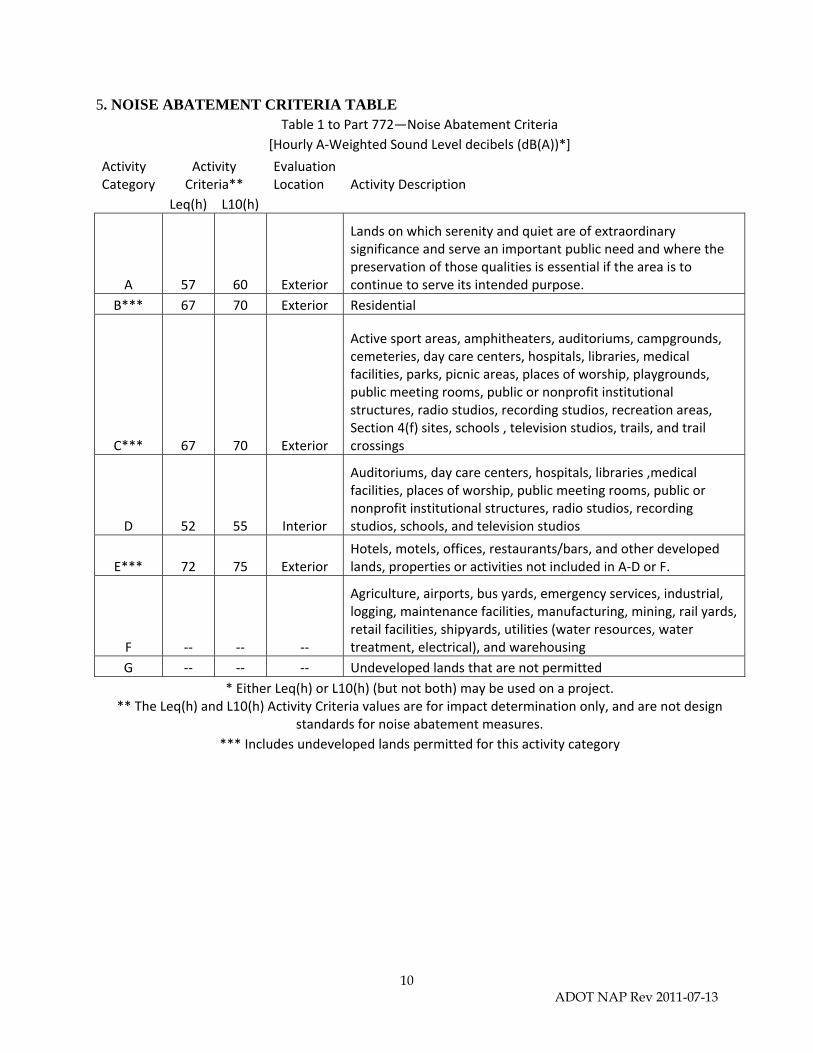
5. NOISE ABATEMENT CRITERIA TABLE Table 1 to Part 772—Noise Abatement Criteria
[Hourly A‐Weighted Sound Level decibels (dB(A))*]
Activity Category
Activity Criteria**
Evaluation Location Activity Description
Leq(h) L10(h)
A 57 60 Exterior
Lands on which serenity and quiet are of extraordinary significance and serve an important public need and where the preservation of those qualities is essential if the area is to continue to serve its intended purpose.
B*** 67 70 Exterior Residential
C*** 67 70 Exterior
Active sport areas, amphitheaters, auditoriums, campgrounds, cemeteries, day care centers, hospitals, libraries, medical facilities, parks, picnic areas, places of worship, playgrounds, public meeting rooms, public or nonprofit institutional structures, radio studios, recording studios, recreation areas, Section 4(f) sites, schools , television studios, trails, and trail crossings
D 52 55 Interior
Auditoriums, day care centers, hospitals, libraries ,medical facilities, places of worship, public meeting rooms, public or nonprofit institutional structures, radio studios, recording studios, schools, and television studios
E*** 72 75 Exterior Hotels, motels, offices, restaurants/bars, and other developed lands, properties or activities not included in A‐D or F.
F ‐‐ ‐‐ ‐‐
Agriculture, airports, bus yards, emergency services, industrial, logging, maintenance facilities, manufacturing, mining, rail yards, retail facilities, shipyards, utilities (water resources, water treatment, electrical), and warehousing
G ‐‐ ‐‐ ‐‐ Undeveloped lands that are not permitted
* Either Leq(h) or L10(h) (but not both) may be used on a project. ** The Leq(h) and L10(h) Activity Criteria values are for impact determination only, and are not design
standards for noise abatement measures.
*** Includes undeveloped lands permitted for this activity category
11 ADOT NAP Rev 2011-07-13
6. ANALYSIS OF NOISE ABATEMENT MEASURES When traffic noise impacts are identified, noise abatement shall be considered and evaluated
for feasibility and reasonableness. Each analysis should consider the following abatement measures: Acquisition of Right-of-Way to provide a Buffer Zone Change to Horizontal or Vertical Alignment Insulation of Category D land use facilities when exterior noise abatement is not feasible
and reasonable Traffic Management Measures
o Control Devices o Traffic/Vehicle Restrictions
Noise Barriers o Noise Walls o Noise Berms o Combination Wall/Berm
a. Line-of-Sight When feasible/reasonable to do so, abatement measures should be designed to at least break
the line-of-sight between traffic and receivers so as to achieve the maximum noise abatement.
b. Other Measures 1. Vegetation/Landscaping: As it requires 100’ of dense evergreen vegetation to provide a
noticeable reduction in noise levels, this may not be considered for abatement of highway noise.
2. Quiet Pavements: May not be used as an abatement measure on Federally funded or approved projects unless specifically included in an FHWA-approved Quiet Pavement Pilot Program.
a. ADOT and FHWA currently have an Agreement which allows ADOT to investigate the use of rubberized asphalt as a potential noise abatement measure for noise impacts on Type-1 projects. Application of this abatement measure is pending the results of the Quiet Pavement Pilot Program research project.
7. FEASIBILITY a. Engineering Feasibility The initial consideration for each potential abatement measure should be the engineering factors that determine whether it is possible to design and construct the measure. These factors include:
1. Safety: abatement measures will not be constructed in such a way as to create a potential safety hazard or to inhibit response to a safety emergency.
2. Barrier height: Due to safety, structural and wind load considerations, ADOT will not normally construct noise barriers higher than 20 feet .
3. Topography: the topography of the local area may potentially preclude the use or reduce the effectiveness of certain noise abatement measures such as barriers and berms.
4. Drainage: any noise abatement measure constructed must provide for adequate drainage, both as a safety concern and to prolong the lifespan of the roadway.
5. Utilities: in the event of a conflict between existing or planned utilities and potential noise abatement measures, any extra cost involved with utility relocation or modification may be included in the wall cost when comparing against the cost-per-benefited-receptor.

12 ADOT NAP Rev 2011-07-13
6. Maintenance requirements: abatement measures must be designed and constructed in such a way as to allow access to perform maintenance activities both for the barrier and for adjacent properties.
7. Access to adjacent properties: abatement measures must not be designed or constructed in a manner that denies access to any property adjacent to the barrier.
8. Overall project purpose: the use of abatement measures must be consistent with the overall purpose of the project.
b. Acoustic Feasibility The FHWA noise regulation at 23 CFR 772.13(d)(1)(i) requires each State highway agency to set a criterion for acoustic feasibility. In some instances, the noise level at a particular location may be affected by an alternate noise source such as other roadways/streets, railroads, industrial facilities, and airplane flight paths. In such locations, noise abatement for the proposed transportation project may not be acoustically feasible, since a substantial overall noise reduction cannot be achieved due to other noise sources. To be considered acoustically feasible, a noise abatement measure must achieve at least a 5 dB(A) reduction at 50% of impacted receptors. In such cases, the noise analysis for the location must consider the impact of the alternate noise source when determining acoustic feasibility. Regardless of the presence of alternate noise sources, barriers which are otherwise reasonable and feasible will be constructed. 8. REASONABLENESS There are three reasonableness factors or “tests” that must be met for a noise abatement measure to be considered reasonable: a. Viewpoints or Preferences of Property Owners and Residents The preferences of the property owners and residents of the benefited receptors of a noise barrier will be taken into account when determining whether the barrier is considered reasonable. Noise barriers that are otherwise feasible and reasonable will automatically be considered to be desired unless the public involvement aspect of the NEPA process indicates that a substantial portion of benefited receptors are opposed to the barriers. In that case, ADOT will make a good faith effort to determine the preferences of the property owners and/or legal occupants of each benefited receptor location through a survey process. If less than a 50% response rate of property owner and residents is achieved and a substantial portion of the received responses are opposed to the recommended abatement measures, then further outreach will be attempted through the use of public meetings until either a 50% response rate is achieved or it becomes apparent that such a level of response is not possible due to situational concerns. ADOT will make a decision as to the reasonableness of the recommended mitigation based on the results of this process. b. Noise Reduction Design Goal Noise barriers should be designed to reduce projected unmitigated noise levels by at least 7 dBA for benefited receptors closest to the transportation facility. To be considered reasonable, at least half of the benefited receptors in the first row shall achieve this level of noise reduction.. c. Cost Effectiveness The maximum reasonable cost of abatement is $49,000 per benefited receptor (cost-per-benefited-receptor) with barrier costs calculated at $35 per square foot, $55 per square foot if constructed on a structure. The cost of an abatement measure is the total cost of that measure
13 ADOT NAP Rev 2011-07-13
divided by all the benefited receptors protected by that abatement. The cost-per-benefited-receptor and barrier-cost-per-square-foot require FHWA approval, and will be re-calculated on a regular interval, not to exceed five years, in the following manner:
The cost-per-benefited receptor is determined by taking the square-foot cost of barriers determined below and multiplying by 1400 square feet.
The square-foot cost of barriers is determined by taking the greater of the current square-foot cost value or the average cost of construction of actual barriers for the preceding 5 years + 20%.
The current values were approved by FHWA on 07/13/2011. 1. Third Party Funding Third party funding cannot be used to make up the difference in cost between the reasonable cost-per-benefited-receptor and the actual cost of the barrier. Third party funding can only be used to pay for additional features such as landscaping, aesthetic treatments, alternative barrier materials, etc. for noise barriers that are feasible and already meet cost-effectiveness criteria. 9. INVENTORY AND REPORTING OF ABATEMENT MEASURES ADOT shall maintain an inventory of all constructed noise abatement measures, including the following parameters: Type of abatement; Cost (overall cost, unit cost per/sq. ft.); Average height; Length; Area; Location (State, county, city, route); Year of construction; Average insertion loss/noise reduction as reported by the model in the final noise analysis or
most recent addendum; NAC category(s) protected; Material(s) used in construction (i.e., precast concrete, berm, block, cast in place concrete, brick,
metal, wood, fiberglass, combination, plastic [transparent, opaque, other]; Features (i.e., absorptive, reflective, surface texture); Foundation (ground mounted, on structure); and Project type (Type I, Type II, and optional project types such as State funded, county funded,
tollway/turnpike funded, other, unknown). This information shall be reported to FHWA as requested by either the FHWA Division office or FHWA Resource Center 10. INTERACTION WITH LOCAL JURISDICTIONS a. Consultation with Local Jurisdictions ADOT will consult with all local jurisdictions as part of the noise analysis process, and will consider the wishes of the local jurisdiction when considering noise abatement measures. b. Use of Local Jurisdiction Noise Abatement Policies on FHWA Projects Any FHWA-funded or –approved project which is administered by a Local Public Agency and which meets the requirements for a Type I project will utilize the ADOT Noise Abatement
14 ADOT NAP Rev 2011-07-13
Policy for determination of traffic noise impacts and feasibility/reasonableness of potential noise abatement. c. Noise Compatible Land Use Planning For any project where there are Category G lands, future noise levels at and approximately 300’ away from the right of way line will be predicted for each segment of undeveloped lands. Following FHWA approval of the Noise Study Technical Report, this information will be made available to the local officials with the responsibility for making zoning/permitting decisions for that location. This information will be accompanied by the statement: “This information is presented purely to assist with noise-compatible land use planning decision making. Abatement for lands permitted after the Date of Public Knowledge for this project is not eligible for Federal Aid.” 11. FEDERAL PARTICIPATION For Type I projects, federal funds may be used for noise abatement measures when traffic noise impacts have been identified and abatement measures have been determined to be feasible and reasonable. These abatement measures which may be considered include noise barriers, traffic management measures, horizontal or vertical alignment alterations, acquisition of property to serve as a buffer zone, or noise insulation of activity category D land use facilities. Post-installation maintenance and operational costs for noise insulation are not eligible for Federal-aid funding. 12. CONSTRUCTION NOISE ADOT’s Standard Specifications for Highway and Bridge Construction (ADOT 2008b) stipulate that all exhaust systems on equipment should be in good working order and properly designed engine enclosures and intake silencers should be used where appropriate. The Standard Specifications also stipulate that ADOT employees and contractors will follow all local rules and ordinances; this includes any local ordinances related to construction site and equipment. For all Type I Projects, ADOT will consider the effects of noise from project construction activities and will determine any additional measures that are needed in the plans or specifications to minimize or eliminate adverse impacts from construction noise. To minimize noise impacts during construction, each noise study should recommend that stationary or idling equipment be located as far away from receptors as possible. Any abatement measures dealing with construction noise determined to be necessary, reasonable, and feasible will be included in the project plans and specifications.

39820 Federal Register / Vol. 75, No. 133 / Tuesday, July 13, 2010 / Rules and Regulations
by reference at the National Archives and Records Administration (NARA). For information on the availability of this material at NARA, call 202–741– 6030, or go to: http://www.archives.gov/ federal_register/ code_of_federal_regulations/ ibr_locations.html.
Issued in Renton, Washington, on June 25, 2010. Ali Bahrami, Manager, Transport Airplane Directorate, Aircraft Certification Service. [FR Doc. 2010–16435 Filed 7–12–10; 8:45 am]
BILLING CODE 4910–13–P
DEPARTMENT OF TRANSPORTATION
Federal Highway Administration
23 CFR Part 772
[FHWA Docket No. FHWA–2008–0114]
RIN 2125–AF26
Procedures for Abatement of Highway Traffic Noise and Construction Noise
AGENCY: Federal Highway Administration (FHWA), DOT. ACTION: Final rule.
SUMMARY: This final rule amends the Federal regulations on the Procedures for Abatement of Highway Traffic Noise and Construction Noise. The final rule clarifies and adds definitions, the applicability of this regulation, certain analysis requirements, and the use of Federal funds for noise abatement measures.
DATES: Effective date: July 13, 2011. Incorporation by reference: The
incorporation by reference of certain publications listed in the regulations is approved by the Director of the Federal Register as of July 13, 2011. FOR FURTHER INFORMATION CONTACT: Mr. Mark Ferroni, Office of Natural and Human Environment, (202) 366–3233, or Mr. Robert Black, Office of the Chief Counsel, (202) 366–1359, Federal Highway Administration, 1200 New Jersey Avenue, SE., Washington, DC 20590.
SUPPLEMENTARY INFORMATION:
Electronic Access
This document and all comments received by the DOT Docket Facility, Room PL–401, may be viewed through www.regulations.gov. Regulations.gov is available 24 hours each day, 365 days each year. Electronic submission and retrieval help and guidelines are available under the help section of this Web site.
An electronic copy of this document may be downloaded by using a computer, modem, and suitable communications software from the Government Printing Office’s Electronic Bulletin Board Service at (202) 512– 1661. Internet users may also reach the Office of the Federal Register’s home page at: http://www.archives.gov and the Government Printing Office’s Web page at: http://www.access.gpo.gov/nara.
Background The FHWA developed the noise
regulation as required by section 136 of the Federal-Aid Highway Act of 1970 (codified at 23 U.S.C. 109(i)). The regulation applies to highway construction projects where a State department of transportation has requested Federal funding for participation in the project. The FHWA noise regulation, found at 23 CFR 772, requires a highway agency to investigate traffic noise impacts in areas adjacent to federally funded highways for the proposed construction of a highway on a new location or the reconstruction of an existing highway that either significantly changes the horizontal or vertical alignment or increases the number of through-traffic lanes. If the highway agency identifies impacts, it must consider abatement. The highway agency must incorporate all feasible and reasonable noise abatement into the project design.
The FHWA published the ‘‘Highway Traffic Noise Analysis and Abatement Policy and Guidance’’ (Policy and Guidance), dated June 1995 (available at http://www.fhwa.dot.gov/environment/ noise/polguide/polguid.pdf), which provides guidance and policy on highway traffic and construction noise abatement procedures for Federal-aid projects. While updating the 1995 Policy and Guidance, the FHWA determined that certain changes to the noise regulations were necessary.
As a result, the FHWA published a Notice of Proposed Rulemaking (NPRM) on September 17, 2009 (74 FR 47762). This final rule amends sections 772.1, 772.5 to 772.17, and Table 1—Noise Abatement Criteria. Sections 772.3 and 772.19 are not amended by this final rule, and Appendix A—National Reference Energy Mean Emission Levels as a Function of Speed, is removed by this final rule. This final rule also reorganizes various sections and parts of sections throughout the NPRM to institute a more logical order in the regulation. This reorganization does not change the meaning of the regulation and is not substantive in nature.
In the preamble of the NPRM, the FHWA specifically asked for comments
on the cost of abatement, third party funding for abatement, and maintaining a noise abatement inventory. The FHWA appreciates the comments received on this section. A summary of the comments received and the FHWA’s response to these comments can be found in the discussion of comments section.
The preamble of the NPRM requested comments on a proposed timeline for highway agencies to revise and have the FHWA approve their noise policies. Changes to this timeline have been made based on the comments received. Therefore, highway agencies will need to submit their revised noise policy, meeting the requirements of this final rule, to FHWA for approval within 6 months from the publication date of this final rule. The FHWA will review the highway agency’s revised noise policy for conformance to the final rule and uniform and consistent application nationwide. The highway agency will provide FHWA a review schedule for approval of their revised noise policy that does not exceed 3 months from the highway agency’s first submission of the revised noise policy to the FHWA. Each review of the document by FHWA should have a duration of at least 14 days for the initial and subsequent reviews. The highway agency’s main point of contact for this review will be the FHWA Division Office in their State. Each highway agency’s revised noise document will be concurrently reviewed by three FHWA offices to ensure uniform and consistent application of this final rule nationwide (one from the respective Division Office, one from the Resource Center, and one from Headquarters). Failure to submit a revised noise policy in accordance with the final rule could result in a delay in FHWA’s approval of Federal-aid highway projects that require a noise analysis. The highway agency would be required to implement the new standard no later than 12 months from the date this final rule was published in the Federal Register.
Grandfathering to the pre-final rule of 23 CFR 772 should be considered for Federal-aid highway projects for which the Categorical Exclusion, Finding of No Significant Impact, or Record of Decision has been signed by the effective date of this final rule. The State highway agency should coordinate with their FHWA Division Office to determine which projects, if any, should be completed under the previous 23 CFR 772 and highway agency’s previously approved noise policy.
The FHWA has updated the Policy and Guidance document to reflect what is presented in this final rule. Highway
VerDate Mar<15>2010 16:12 Jul 12, 2010 Jkt 220001 PO 00000 Frm 00034 Fmt 4700 Sfmt 4700 E:\FR\FM\13JYR1.SGM 13JYR1jlent
ini o
n D
SK
J8S
OY
B1P
RO
D w
ith R
ULE
S

39821 Federal Register / Vol. 75, No. 133 / Tuesday, July 13, 2010 / Rules and Regulations
agencies should use this document for additional guidance when developing their revised noise policies in compliance with this final rule. To further assist highway agencies in revising their noise policies, the FHWA has developed a policy template for the highway agencies to use if they desire to do so. The updated guidance and optional policy template can be found at: http://www.fhwa.dot.gov/ environMent/noise/index.htm.
Discussion of Comments The agency received comments from
25 State highway agencies (California, Florida, Georgia, Illinois, Kentucky, Louisiana, Maryland, Massachusetts, Michigan, Minnesota, Mississippi, Missouri, Montana, North Carolina, New Jersey, New York, Ohio, Oregon, Pennsylvania, South Carolina, Tennessee, Texas, Virginia, Washington, and Wisconsin), 1 county highway agency (Anoka County Highway Department, Minnesota), 1 national organization (American Association of State Highway and Transportation Officials (AASHTO)), 7 noise consultants or consulting firms (Bergmann Associates, Inc., Bowlby & Associates, Environmental Acoustics, Inc., Environmental Science Associates, HNTB Corporation, Karel Cubic and Sharon Paul Carpenter), 1 university (East Carolina University), and 1 private citizen (Jennifer Leigh Hanson).
There were several comments received that were general in nature. Three State highway agencies and one private consultant expressed that they generally agreed with the NPRM. One private consultant commented that the numbering of the regulation should not skip the even numbers. The FHWA will retain the numbering sequence that the regulation currently has. One private consultant commented on the parentheses used on the ‘‘A’’ of dB(A). It is FHWA’s position that since the metric used to assess highway traffic noise levels is the A-weighted decibel, that decibel be illustrated by ‘‘dB’’ and the parentheses are needed around the ‘‘A’’ to illustrate the A-weighting. The parentheses are commonly used by the highway noise industry and will be retained in the final rule. Two State highway agencies and a university commented that quiet pavements should be allowed as a federally funded noise abatement measure. While the FHWA recognizes the efforts of many State highway agencies and the pavement industries, there are still too many unknowns that currently prohibit the use of pavement as a noise abatement measure. One national organization commented that while they
recognize the importance of uniform and consistent application of this regulation nationwide, they encourage the FHWA to incorporate flexibility to accommodate regional and State- specific needs. The FHWA has incorporated flexibility while setting specific parameters throughout this final rule. There are numerous situations in the final rule where the State highway agency is permitted to completely define a definition or process, or define a definition or process within the parameters set by the FHWA.
Based on comments received, the FHWA has changed the order and titles of several of the sections. The current section 772.17 ‘‘Traffic Noise Predication’’ is now section 772.9, with the same title. The current section 772.9 ‘‘Analysis of traffic noise impacts and abatement measures’’ is now section 772.11, with the title ‘‘Analysis of traffic noise impacts.’’ The ‘‘and abatement measures’’ of this title has been removed as it is redundant with the noise abatement section. The current section 772.11 ‘‘Noise abatement’’ is now section 772.13, with the new title of ‘‘Analysis of noise abatement,’’ which keeps consistent with the previous section dealing with the analysis of traffic noise impacts. The current section 772.13 ‘‘Federal participation’’ is now section 772.15 with the same title. The current section 772.15 ‘‘Information for local officials’’ is now section 772.17 with the same title.
Section-by-Section Discussion of Comments
Section 772.1—Purpose
In section 772.1, the FHWA is adding the word ‘‘livability’’ to this section, not based on comments received, but to incorporate the DOT Secretary’s livability initiative.
Section 772.3—Noise Standards
In section 772.3, no changes have been made to this section based on comments received; however, one State highway agency commented on the difference between the use of the words ‘‘accordance’’ and ‘‘conformance.’’ The FHWA did not use these two terms to show a difference in meaning, but rather to illustrate agreement between both the regulation and the noise standard.
Section 772.5—Definitions
In section 772.5, three State highway agencies and one private consultant commented that the definitions should be placed in alphabetical order. The FHWA agrees and the definitions are now listed and discussed in this final rule in alphabetical order. Also, one
State highway agency suggested adding a definition for substantial noise reduction. The FHWA disagrees with the addition of ‘‘substantial noise reduction’’ since this principle is adequately addressed in the other sections of the final rule.
Benefited Receptor, 10 State highway agencies, 1 national organization, and 5 private consultants commented on the definition of benefited receptor. Eleven commenters generally support the definition with minor or no revisions, with two comments desiring additional flexibility in defining and applying benefited receptors. Three comments concerned the issues of benefited receptors that are impacted and benefited receptors that are not impacted, and two comments were concerned with a discernable 5 dB(A) change in noise versus a perceptible 3 dB(A) change in noise.
The FHWA has changed the definition to indicate that a benefited receptor is a ‘‘recipient of an abatement measure that receives a noise reduction at or above the minimum threshold of 5 dB(A), but not to exceed the highway agency’s reasonableness design goal.’’ The definition retains the 5 dB(A) minimum threshold, but provides flexibility to State highway agencies by allowing the agency to define a benefited receptor as one benefitting from a reduction in noise level that is between 5 dB(A) and the agency’s design goal. These changes ensure construction of effective noise abatement measures. Generally, a 5 dB(A) change in noise levels is deemed discernible by a person with normal hearing. Noise abatement activities should result in a discernible 5 dB(A) change in noise level rather than a perceptible 3 dB(A) change in noise level. This approach provides a consistent approach throughout this final rule. State highway agencies will still be able to differentiate between benefiting impacted and non-impacted receivers within their own policies. States may continue weighting impacted receptors greater than non-impacted receptors when making decisions about reasonableness of noise abatement.
Common Noise Environment, seven State highway agencies, one national organization, and three private consultants commented on the definition of common noise environment. The definition was generally supported with minor changes or clarifications requested. Two commenters disagreed with the definition. Based on a comment from the New York DOT, the FHWA has added ‘‘within the same Activity Category in Table 1’’ to the definition,
VerDate Mar<15>2010 16:12 Jul 12, 2010 Jkt 220001 PO 00000 Frm 00035 Fmt 4700 Sfmt 4700 E:\FR\FM\13JYR1.SGM 13JYR1jlent
ini o
n D
SK
J8S
OY
B1P
RO
D w
ith R
ULE
S

39822 Federal Register / Vol. 75, No. 133 / Tuesday, July 13, 2010 / Rules and Regulations
with the other comments being addressed in sec. 772.13 Analysis of Noise Abatement. The FHWA is addressing the concept of common noise environment by defining the parameters for cost averaging to ensure cost averaging is applied uniformly and consistently nationwide. States can continue to consider each neighborhood as its own noise environment. The definition allows States flexibility to consider common noise environments within the project. A noise analysis should consider secondary sources, including non-highway noise sources, as part of the common noise environment. The final rule acknowledges that a common noise environment may span an entire project area and requires consideration of a common noise environment for land uses within the same activity category.
Date of Public Knowledge, one State highway agency, one national organization, and one private consultant agreed and supported the addition of this definition. No changes were made based on comments received, however, ‘‘CE’’ and ‘‘ROD’’ were spelled out and ‘‘as defined in 23 CFR 771’’ was added to provide additional clarification.
Noise Reduction Design Goal, based on comments received, the FHWA is defining ‘‘noise reduction design goal’’ to be ‘‘[t]he optimum desired dB(A) noise reduction determined from calculating the difference between future build noise levels with abatement, to future build noise levels without abatement. The noise reduction design goal shall be at least 7 dB(A), but not more than 10 dB(A).’’ The FHWA is defining ‘‘Noise Reduction Design Goal’’ to remove the disconnect that occurs with a 5 dB(A) substantial decrease criterion and substantial increase criteria’s 5–15 dB(A) range.
Design Year, two State highway agencies, one national organization, and a private consultant commented in support of the definition of design year. The FHWA made no changes to this definition in the final rule.
Existing Noise Levels, two State highway agencies, one national organization, and one private consultant commented on the definition of existing noise levels. Most comments expressed support of the definition with minor clarifications. One State highway agency sought additional clarification on what are, and how to address, non-highway traffic noise sources. It is FHWA’s position that an effective noise analysis should consider major noise sources in the environment including transportation, industry, and background noise.
Feasibility, two State highway agencies, one national organization, and two private consultants commented on the definition of feasibility. The definition was generally supported with minor revisions. Based on the comments, the FHWA added ‘‘considered in the evaluation of’’ to the definition to clarify that the combination of acoustical and engineering factions shall be examined when considering noise abatement measures. Other comments dealt with how to apply feasibility and therefore are better suited to in sec. 772.13 where feasible noise abatement is further addressed.
Impacted Receptor, four State highway agencies, one national organization, and two private consultants submitted comments generally supportive of the definition of impacted receptor, with minor revisions regarding redundancy, and allowing State highway agencies to define. The FHWA made several changes to this definition. The definition was simplified by removing the text that made it redundant with the definition of traffic noise impacts.
L10, four State highway agencies, one national organization, and two private consultants commented on this definition. Many of the comments recommended the definition be deleted because the metric is obsolete. Although currently the L10 metric is not the most applicable metric to use on highway projects, the L10 and Leq metrics were a part of this regulation from its genesis. As a result, the State of Minnesota has a law requiring the use of L10, and therefore this metric will remain in the final rule with no changes.
Multifamily Dwelling, six State highway agencies, a national organization, and two private consultants generally support the definition of multifamily dwellings with some minor revisions including, allowing the highway agency to define the term, and a request for addition flexibility and additional guidance from the FHWA. Massachusetts DOT disagreed with the definition, indicating that, as proposed, the definition of multifamily structures would skew the cost reasonableness calculations. It is FHWA’s position that the purpose of any environmental analysis is to quantify impacts first, and explore methods to mitigate those impacts. The approach of only looking at first floor receptors ignores the possibility that impacts may occur at upper floor residences. The analysis to determine impacts shall be for all outdoor areas of frequent human use, both on the ground and on balconies (if present). This does
not automatically result in feasible and reasonable noise abatement measures being determined for upper lever receptors. When a multifamily dwelling has a common exterior area of frequent human use, each unit of the multifamily dwelling that has access to that common exterior shall be included in the feasible and reasonable analysis. Multifamily development does not ‘‘skew’’ the determination of feasible and reasonable noise abatement measures. Providing noise abatement for multifamily development results in noise abatement for a higher number of people who may be using individual or common exterior areas. Frequency of use is not based on a comparison between how a single family dwelling would use their outdoor area versus how a multifamily dwelling would use their outdoor area. This process allows all receptors to be analyzed for noise impacts, and allows all impacted receptors to be considered for noise abatement. To add clarification, the FHWA added ‘‘when determining impacted and benefiting receptors’’ to the end of the second sentence.
Noise Barrier, based on comments received, the FHWA is defining ‘‘noise barrier’’ to be ‘‘[a] physical obstruction that is constructed between the highway noise source and the noise sensitive receptor(s) that lowers the noise environment, to include stand alone noise walls, noise berms (earth or other material), and combination berm/wall systems.’’ Noise barriers have been a longstanding proven noise abatement measure and therefore it is necessary to clarify that a noise barrier can be a wall, berm or a combination berm/wall system.
Permitted, three State highway agencies, one national organization, one county highway department, and one private consultant commented that there should be more of a definite commitment to develop, and therefore suggested renaming this definition ‘‘permitted’’ instead of ‘‘planned, designed and programmed.’’ There was also a comment to retain flexibility in interpreting a definite commitment. The FHWA agrees, and has changed this definition to ‘‘permitted’’ and removed all references to ‘‘planned, designed and programmed’’ from the final rule. The FHWA also added ‘‘as evidence by issuance of a building permit’’ to the definition.
Property Owner, three State highway agencies, one national organization, and a private consultant generally supported the definition of ‘‘property owner’’ with minor changes. The FHWA modifies this definition to include ‘‘holds a title,
VerDate Mar<15>2010 16:12 Jul 12, 2010 Jkt 220001 PO 00000 Frm 00036 Fmt 4700 Sfmt 4700 E:\FR\FM\13JYR1.SGM 13JYR1jlent
ini o
n D
SK
J8S
OY
B1P
RO
D w
ith R
ULE
S

39823 Federal Register / Vol. 75, No. 133 / Tuesday, July 13, 2010 / Rules and Regulations
deed or other legal documentation of ownership.’’
Reasonableness, two State highway agencies, one national organization, and two private consultants commented on the definition of ‘‘reasonableness.’’ The definition was generally supported with minor revisions. Based on the comments of a private consultant, the FHWA added ‘‘considered in the evaluation of’’ to the definition to clarify that the combination of social, economic and environmental factions shall be considered when considering noise abatement measures. Other comments provided suggested adding that reasonableness is based on common sense and good judgment. It is FHWA’s position that this leaves reasonableness open to personal opinion rather than using an objective approach and has not made the suggested change in the final rule.
Receptor, based on changes made from comments received, the FHWA is defining ‘‘receptor,’’ to be ‘‘a discrete or representative location of a noise sensitive area(s), for any of the land uses list in Table 1.’’
Residence, four State highway agencies, one national organization and two private consultants commented on their general approval of this definition for ‘‘residence.’’ Additional comments include surveying multifamily residents and the use of a basic unit of measure. A discussion on how to survey multifamily residents is not appropriate for the definition section, but is address later in the final rule.
The NPRM had proposed to define ‘‘severe noise impact’’ in sec. 772.5(s). Nine State highway agencies, one county highway agency, one national organization, and five private consultants commented on the definition of severe noise impact. Based on the comments received, the FHWA has removed this definition from the final rule due to the conflict from the commenters on size and scale of the range, and since the definition would likely be misinterpreted to mean that the noise levels or noise level increases must fall within those ranges.
The NPRM had proposed to define ‘‘special land use facilities’’ in sec. 772.5(e). Seven State highway agencies, one national organization, and three private consultants commented on the definition of ‘‘special land use facilities.’’ The FHWA removed this term from the final rule based on changes to the activity categories presented in Table 1. There are now seven activity categories in order to break out various land uses into more appropriate groupings.
Statement of Likelihood, based on changes made from comments received, the FHWA is defining ‘‘statement of likelihood,’’ to be ‘‘a statement provided in the environmental clearance document based on the feasibility and reasonableness analysis completed at the time of environmental document is being approval.’’
Substantial Construction, six State highway agencies, one county highway agency, one national organization and two private consultants comment on the definition of ‘‘substantial construction.’’ The definition was generally supported with recommendations. Based on the comments received, the FHWA is removing from the definition ‘‘the filing of a plat plan or an occurrence of a similar action,’’ and the word ‘‘original’’ before ‘‘highway.’’ The final rule will retain this definition to help State highway agencies clarify when development must occur for Type II eligibility and for potential Type I reasonableness considerations.
Substantial Noise Increase, based on comments received from eight State highway agencies and two private consultants, the FHWA is defining ‘‘substantial noise increase,’’ to be ‘‘One of two types of highway traffic noise impacts. For a Type I project, an increase in noise levels of 5 to 15 dB(A) in the design year over the existing noise level.’’
Traffic Noise Impacts, four State highway agencies, a national organization, and two private consultants commented on the definition of traffic noise impacts, with general support of the definition. Comments pertained to the inclusion of design year and reference to future condition as well as how to address other noise sources. The FHWA has added ‘‘design year’’ and ‘‘design year build condition’’ to the final rule. It is FHWA’s position that an effective noise analysis should consider major noise sources in the environment including transportation, industry, and background noise. Without a project noise levels may exist that exceed the noise abatement criteria (NAC), but there are no impacts without a project.
Type I Project, 14 State highway agencies, 1 national organization, and 6 private consultants commented on this section. The majority of the comments referenced the use of a 3 dB(A) increase in determining a significant change for a Type I project, followed by the redundancy of the first two sentences, and use of the word ‘‘significant.’’ The FHWA has revised this section to remove the first sentence and replace ‘‘significant’’ with ‘‘substantial.’’ The use of a 3 dB(A) increase in determining a
substantial change has been removed. The factor for determining a substantial horizontal change is a halving the distance between the noise source and the closest receiver between the existing condition to the future build condition. The factor for determining a substantial vertical change is ‘‘a project that removes shielding therefore exposing the line-of-sight between the receptor and the traffic noise source exposing the receptor to additional traffic noise. This is done by either altering the vertical alignment of the highway or by altering the topography between the highway traffic noise source and the receptor.’’
Twelve State highway agencies, 1 national organization, and 4 private consultant firms commented on what constitutes a Type I project for the addition of a through traffic lane or an auxiliary lane. Additional comments were provided on bus lanes, turn lanes, restriping travel lanes, weight stations, toll plazas, ride-share lots, and rest stops. Based on the comments received, the FHWA changed the definition of Type I project to now include bus lanes as through traffic lanes. The definition further clarifies that left turn lanes are not considered an auxiliary lane, and additional qualifying activities were added including ‘‘restriping existing pavement for the purpose of adding a through-traffic lane or an auxiliary lane’’ and ‘‘the addition of a new or substantial alteration of a weigh station, rest stop, ride-share lots and toll plaza.’’ Finally, the FHWA adds clarifying language to make clear that ‘‘if a project is determined to be a Type I project under this definition then the entire project area as defined in the environmental document is a Type I project.’’
Five State highway agencies and one private consultant supported this section and suggested moving the addition of new interchanges or ramps to an existing facility to its own subsection. The FHWA agrees. The final rule will reflect that the ‘‘addition of new interchanges or ramps added to a quadrant to complete an existing partial interchange’’ will be its own section under the Type I definition.
Type II Project, one State highway agency and one private consultant commented that they were in support of this section on Type II projects. One State highway agency commented that it is not necessary for a State highway agency to develop a Type II program. The FHWA disagrees and did not change this section in the final rule. As supported in the 1995 guidance document, a Type II noise abatement program is appropriate to ensure statewide consistency.
VerDate Mar<15>2010 16:12 Jul 12, 2010 Jkt 220001 PO 00000 Frm 00037 Fmt 4700 Sfmt 4700 E:\FR\FM\13JYR1.SGM 13JYR1jlent
ini o
n D
SK
J8S
OY
B1P
RO
D w
ith R
ULE
S

39824 Federal Register / Vol. 75, No. 133 / Tuesday, July 13, 2010 / Rules and Regulations
Type III Project, nine State highway agencies and two private consultants commented on the creation of a Type III project. The majority of the comments were in support of the Type III project type, with some asking FHWA to provide examples of Type III projects and to develop a template for documenting Type III. One commenter requested clarifying that Type III projects do not need a noise analysis performed. The FHWA agrees and, as a result, added ‘‘Type III projects do not require a noise analysis’’ to the definition of a Type III project. Examples of Type III projects and a template for documenting Type III projects will be provided in FHWA guidance.
Section 772.7—Applicability Two State highway agencies and a
private consultant expressed support for the expansion of this section of the regulation. In sec. 772.7(a)(1), one State highway agency expressed support for the proposed change, but a private consultant requested additional clarification because item (1) requires applicability for any project requiring ‘‘FHWA approval regardless of funding sources.’’ Therefore, a highway agency, other than the State DOT, such as a county or local highway agency is required to comply with 23 CFR 772 when one of its projects involves a new or modified access to an Interstate highway. This is a correct interpretation of what the FHWA intended, therefore no changes to this section were made.
In sec. 772.7(a)(2), one State highway agency expressed support for this provision in the regulation. This applies to all Federal and Federal-aid highway projects authorized under Title 23, United States Code. Therefore, this regulation applies to any highway project or multimodal project that is funded with Federal-aid highway funds. A county highway agency stated that the above statement appears to contradict the statement made under the Regulatory Flexibility Act that the proposed rule would not have a significant economic impact on a substantial number of small entities. The rulemaking addresses the obligation of Federal funds to States for Federal- aid highway projects. As such, it affects only States, and States are not included in the definition of small entity set forth in 5 U.S.C. 601. Therefore, the Regulatory Flexibility Act does not apply and the FHWA certifies that the final rule would not have a significant economic impact on a substantial number of small entities. Local public agencies have never had an exemption from complying with 23 CFR 772. The
proposed rule does not present a new economic impact. The proposed changes in the rule will not result in an increase in the likelihood of construction of noise abatement.
In sec. 772.7(b), no comments were received, but the FHWA has modified this section in the final rule to provide additional clarification and to tie into the proposed requirement in the NPRM that this final rule will require State highway agencies to revise their noise polices in conformance with this final rule. The section now states ‘‘For FHWA approval, the highway agency shall develop noise policies in conformance with this regulation and shall apply these policies uniformly and consistently statewide.’’
Section 772.7(d) was proposed in the NPRM as sec. 772.7(c)(1), and is now listed as sec. 772.7(d). Two State highway agencies commented on this section. While one expressed support, the other State highway agency requested clarification on the intent of the section regarding use of State-only funds to avoid noise abatement. It is FHWA’s position that the rule applies to any Federal or Federal-aid project. This means that the regulation applies to any project that includes a Federal action. No changes were made to this section.
Section 772.7(e) was proposed in the NPRM as sec. 772.7(c)(2) and is now listed as sec. 772.7(e). A national organization, eight State highway agencies, and three private consultants commented on this section. Some comments offered support for this clarification of Type II program requirements, while others questioned the need for a priority system and the status of States that already have a system in place. A private consultant recommended insertion of language that the ranking system serves as a guide, but not a requirement for selection for funding. A State highway agency requested a template for a priority system. The FHWA disagrees with the need to incorporate the ranking of potential Type II project as language in the final rule. State highway agencies will submit their existing ranking system to FHWA for approval when they submit their updated noise policies. The concept of a priority system is not new. This is a longstanding practice on the part of States with active Type II programs. The priority system restricts construction of ‘‘political’’ noise barriers under the guise of a Type II program when a State does not actually have a Type II program in place and has no intent of developing a Type II program. The priority system ensures uniform and consistent application of this provision of the rule.
The following was added to this section ‘‘The highway agency shall re-analyze the priority system on a regular interval, not to exceed 5 years.’’ A private consultant recommended adding a new section (3) to include ‘‘If a highway agency chooses to participate in a Type II program, the highway agency must have a statewide outreach program to inform local officials and the public of the items in § 772.15(a)(i)–(iv).’’ If States choose to participate in a Type II program, they should also act to encourage local communities to enact noise compatible land use planning to limit the expenditure of Federal highway dollars to construct Type II noise barriers in the future. The FHWA agrees with the concept, but not with the application of this idea. The circumstances that lead to a Type II project occurred in the past. State highway agencies should take the opportunity of a Type II project to inform local officials about noise compatible planning concepts to avoid future Type I projects. The development of this outreach effort should be a part of any Type II program.
Section 772.7(f), was proposed in the NPRM as sec. 772.7(c)(3) and is now listed as 772.7(f). A State highway agency and a private consultant requested a listing of the types of projects classified as Type III. The FHWA believes the rule clearly states that Type III projects are any project that falls outside the definition of a Type I or Type II project. The FHWA noise guidance provides additional information on this topic. A private consultant suggested adding language that NEPA may require noise analysis on Type III projects. A State highway agency recommended changing ‘‘not required’’ to ‘‘optional.’’ The FHWA declines to make these changes in the final rule. The proposed and final language does not prohibit States from performing a noise analysis on Type III projects if they determine an analysis is necessary due to unusual characteristics of a particular project. Two State highway agencies commented on this section. One recommended elimination of Type III as a descriptor and the other expressed approval of the new designation. The FHWA retains the Type III project designation with no changes.
Section 772.9—Traffic Noise Prediction Section 772.9, traffic noise prediction,
is sec. 772.17 in the existing regulation. Moving the traffic noise prediction section from 772.17 to 772.9 was done to place the activities associated with traffic noise prediction in chronological order with the overall procedures for
VerDate Mar<15>2010 16:12 Jul 12, 2010 Jkt 220001 PO 00000 Frm 00038 Fmt 4700 Sfmt 4700 E:\FR\FM\13JYR1.SGM 13JYR1jlent
ini o
n D
SK
J8S
OY
B1P
RO
D w
ith R
ULE
S

39825 Federal Register / Vol. 75, No. 133 / Tuesday, July 13, 2010 / Rules and Regulations
abating highway traffic noise. Due to the new numbering of this section, the provisions presented below are numbered and identified as presented in this final rule and not how they were presented in the NPRM.
In sec. 772.9(a), one State highway agency and a private consultant commented that FHWA should continue to require use of the Traffic Noise Model (TNM) and remove reference to other models that may be compatible with TNM until alternate models are tested and approved for use through a change in the regulation. These entities further commented that FHWA should limit use of TNM to the most recent version. It is FHWA’s position that the provision in the regulation to use other models determined compatible with TNM must appear in the regulation so that FHWA may work with other software developers in their efforts to implement the TNM acoustic code if their noise models for testing and approval. Therefore, ‘‘or any other model determined to by the FHWA to be consistent with the methodology of the FHWA TNM’’ will remain in the final rule. Lastly, the FHWA will update this regulation as necessary to require use of updated versions of the TNM.
Ten State highway agencies, a national organization, and two private consultants expressed concerns about proposed restrictions on use of the TNM Lookup Tables; four State highway agencies recommended additional restrictions on the use of the TNM Lookup Tables, and one State highway agency along with three private consultants recommended eliminating use of the Lookup Tables, or developing a replacement. This final rule eliminates use of the TNM Lookup Tables in either form to predict noise levels on Federal or Federal-aid projects. The FHWA developed the Lookup tables to provide TNM users with a simple screening tool for highway analyses. The tables were to supplement TNM to obtain quick estimates. The intended use of the estimates is to inform planners about the potential scope of their project, or to educate the public. The Lookup Tables are not a substitute for the TNM or for routine use in performing a noise analysis. Many practitioners started using the Lookup Tables due to long calculation times inherent with the use of the FHWA TNM when compared with the previous model. However, the dramatically increased speed of computers currently available on the market reduces the model run times to a fraction of what could be accomplished a few years ago. Further, a narrow interpretation of the previous rule indicates the changes to the
regulation requiring use of the FHWA TNM eliminated the option to use the TNM Lookup Tables. However, use of the TNM Lookup Tables continued as a legacy. The FHWA has removed this provision proposed in the NPRM from this final rule. The FHWA clarifies through this final rule that the TNM Lookup Tables are not an acceptable model for use on Federal or Federal-aid highway projects. The FHWA will not update the TNM Lookup Tables for future versions of the FHWA TNM. The FHWA will retract the allowable use of the TNM Lookup as it has outlived its intended use.
In sec. 772.9(b), two State highway agencies and a university commented that quieter pavement should be allowed as a mitigation measure. As previously discussed, it is FHWA’s position that there are still too many unknowns regarding the viability of quieter pavements as a mitigation measure. However, State highway agencies, the pavement industry, and the FHWA are researching various parts of this overall initiative. The FHWA is actively researching how to better incorporate more specific pavement types in the FHWA TNM. As a result the FHWA added this provision which states, ‘‘average pavement type shall be used in the FHWA TNM for future noise level prediction unless a highway agency substantiates the use of a different pavement type for approval by the FHWA.’’ However, the FHWA is actively seeking highway agencies to assist in our research to better account for pavements in the FHWA TNM by engaging themselves in the experimental use of the specific pavement types currently in the FHWA TNM on projects.
In sec. 772.9(c), six State highway agencies, a national organization, and two private consultants questioned restrictions or wanted additional clarification on the use of noise contours. The final rule ties use of noise contours to information provided to local officials to satisfy sec. 772.17 Information for Local Officials and permits use of contours for some preliminary studies.
Section 772.11—Analysis of Traffic Noise Impacts
Section 772.11, titled ‘‘analysis of traffic noise impacts,’’ was sec. 772.9 in the proposed regulation. The FHWA has removed ‘‘and abatement measures’’ from the title of this section since sec. 772.13 of the final rule now deals with abatement measures. Due to the new numbering of this section, the provisions presented below are identified as presented in this final rule
and not how they were numbered in the NPRM. This and other organizational changes were done in response to a comment from a private consultant, who indicated that this section should separate the analysis and abatement portions into their respective sections of the regulation, and pointed out that there is a long-standing disconnect between the intent of this portion of the regulation and the practice of most State highway agencies in applying the regulation. The first condition is ‘‘where no exterior activities are to be affected by the traffic noise.’’ The typical application would be an apartment building with no outdoor balconies, patios, or common grounds activity areas. The second condition is ‘‘where the exterior activities are far from or physically shielded from the roadway in a manner that prevents an impact on exterior activities.’’ The implication of the second condition is that if the apartment, pool, and playground are on the side of the building away from the highway then one would need to consider the interior of the apartments facing the highway as Activity Category E. Few State highway agencies currently consider apartments as Category E. Instead, they analyze the playground and pool as exterior Category B, find that they are not impacted, and then fail to consider abatement for the apartments.
In sec. 772.11, one State highway agency had a general comment requesting that FHWA provide an opinion on a highway agency changing its definition of ‘‘substantial increase.’’ It is the opinion of the FHWA that highway agencies may decide at its discretion to change established criterion within the allowable requirement of this final rule. However, highway agencies should consider past practices and the possible consequences of any changes they make to their noise policy and procedures.
No comments were received on sec. 772.11(a), but to provide clarification on how to analyze projects, the FHWA added sec. 772.11(a)(1) ‘‘For projects on new alignments, determine traffic noise impacts by field measurements’’ and sec. 772.11(a)(2) ‘‘for projects on existing alignments, prediction of existing and design year traffic noise impacts.’’
In sections 772.11(a)(1) and (a)(2), three State highway agencies and two private consultants requested rewording of this section to clarify determination of existing and future noise levels. The final rule clarifies that existing levels are determined through measurement or prediction. This is because there are times when the ‘‘existing’’ condition and the current year are not the same year.
VerDate Mar<15>2010 16:12 Jul 12, 2010 Jkt 220001 PO 00000 Frm 00039 Fmt 4700 Sfmt 4700 E:\FR\FM\13JYR1.SGM 13JYR1jlent
ini o
n D
SK
J8S
OY
B1P
RO
D w
ith R
ULE
S

39826 Federal Register / Vol. 75, No. 133 / Tuesday, July 13, 2010 / Rules and Regulations
In this case, predicting existing noise levels is necessary. The final rule clarifies prediction of future noise levels. A State highway agency requested clarification on determining existing noise levels on new alignment projects; the final rule covers new alignment and modification of existing alignment scenarios.
Two private consultants commented on sec. 772.11(b). One requested a definition of frequent human use and the other recommended a connection between exterior areas and frequent human use. The FHWA did not provide a definition for frequent human use, but did make the connection between exterior areas and frequent human use, by stating ‘‘In determining traffic noise impacts, a highway agency shall give primary consideration to exterior areas where frequent human use occurs.’’ The FHWA also moved this provision to sec. 772.11 Analysis of traffic noise impacts.
In sec. 772.11(c)(1), one State highway agency expressed support for this provision while a second State highway agency requested expansion of the language to allow analysis of a single worst-case alternative in place of similar multiple project alternatives. It is FHWA’s position that the language in the final rule does not preclude analysis of a worst-case scenario during preliminary engineering and early environmental studies; however, the highway agency must analyze all alternatives under detailed study as part of a final noise analysis.
Under sec. 772.11(c)(2), one national organization, four State highway agencies, and one private consultant sought additional clarification on the level of analysis necessary for various land use categories and project alternatives. They also suggested deemphasizing land uses previously listed in Activity Category C, which are primarily commercial activities. It is the FHWA’s position that this provision of the rule does not require a separate noise analysis for each Activity Category. The rule requires that the noise analysis include a complete noise analysis of all land uses inside the project study area. Past practice of many highway agencies was to ignore certain Activity Categories, particularly Category C, because the highway agency determined that it is not reasonable to provide noise abatement for that Activity Category. Reasonableness decisions cannot precede determination of impacts. The regulation first requires consideration of impacts, then consideration for abatement. The focus of a noise analysis has always been, and will continue to be, on exterior areas of frequent human use. Consideration of
Activity Category C land use is unlikely to result in a large increase in the number of receivers within a noise model because Category C receptors do not necessarily have areas of frequent human use.
In sec. 772.11(c)(2)(i), three State highway agencies and two private consultants commented on Activity Category A, offering general support or minor wording changes. One of the State highway agencies requested additional clarification on when to start the process to designate a land use as Category A and suggested that this may work better through inter-agency consultation rather than through FHWA approval. The FHWA has determined the recommended wording changes are unnecessary. It is appropriate for the determination of Activity Category A receptors to occur early in the process and through the inter-agency consultation process; however, the final determination for this designation remains a FHWA decision. To further clarify Activity Category A, ‘‘the exterior impact criteria for lands * * *.’’ has been added to this provision.
In sec. 772.11(c)(2)(ii), in response to comments received, the designation of Activity Category B has been revised to include the exterior criteria for only residential land uses. The provision states, ‘‘[t]his activity category includes the exterior impact criteria for single- family and multifamily residences.’’
In sec. 772.11(c)(2)(iii), eight State highway agencies, one national organization, and one private consultant commented their general support of this provision and requested that FHWA provide a standardized method to evaluate reasonableness for special land use facilities. The term ‘‘special land use facilities’’ has been removed from the final rule. There are several logical and fair ways to evaluate certain types of land use, one approach is the Florida Department of Transportation’s method. The FHWA will provide examples of other methods in the updated noise guidance document. The final rule changes references from special land uses to the actual activity category based on the reorganized Table 1. To provide additional clarification, the designation of Activity Category C has been revised to include a variety of land use facilities as listed in Table 1. This provision states ‘‘Activity Category C. This activity category includes the exterior impact criteria for a variety of land use facilities. Each highway agency shall adopt a standard practice for analyzing these land use facilities that is consistent and uniformly applied statewide.’’
In sections 772.11(c)(2)(iv), (v), and (vi), three State highway agencies and three private consultants offered comments on this section. Two highway agencies offered general support, however, the remaining highway agency and the private consultants offered suggestions on consideration of commercial land use in a noise analysis. The final rule modifies Table 1 to segregate certain commercial land use from noise generating commercial and industrial land uses.
One private consultant requested additional clarification on the timing of interior noise studies in sec. 772.11(c)(2)(iv). The consideration for the analysis may occur prior to noise monitoring. It is FHWA’s position that the noise analyst should be able to identify interior locations that require monitoring during preliminary field work while developing a monitoring plan. One national organization and eight State highway agencies requested additional clarification on the analysis requirements for interior areas. It is FHWA’s position that an interior analysis is only required when all exterior analysis alternatives are exhausted or in cases where there are no exterior activities. To provide extra clarification on which land use categories can be considered for an interior noise analysis, the FHWA has indicated ‘‘exterior’’ and/or ‘‘interior’’ within each Activity Category.
In sec. 772.11(c)(2)(v), in response to comments received, the designation of Activity Category E has been revised to address the exterior impact criteria for less noise sensitive developed lands.
In response to comments received, a new Activity Category F was created in sec. 772.11(c)(2)(vi) to include developed lands that are not sensitive to highway traffic noise.
In sec. 772.11(c)(2)(vii), the FHWA provided clarification on undeveloped lands. Undeveloped lands were listed as Activity Category D in the NPRM, but due to the changes to Table I, undeveloped lands are now listed under Activity Category G in this final rule. Three State highway agencies commented that this section is overly broad for considering whether a property is planned for development and suggested limiting this consideration to issuance of a building permit. This final rule has revised the existing regulation to limit consideration to the issuing of a building permit. Five State highway agencies requested further clarification on the purpose of predicting noise levels on undeveloped land. It is FHWA’s position that providing local officials with the best estimate of future
VerDate Mar<15>2010 16:12 Jul 12, 2010 Jkt 220001 PO 00000 Frm 00040 Fmt 4700 Sfmt 4700 E:\FR\FM\13JYR1.SGM 13JYR1jlent
ini o
n D
SK
J8S
OY
B1P
RO
D w
ith R
ULE
S
39827 Federal Register / Vol. 75, No. 133 / Tuesday, July 13, 2010 / Rules and Regulations
noise levels on undeveloped land is a longstanding requirement of 23 CFR 772 and is necessary to help avoid future noise impacts due to incompatible development. The Pennsylvania DOT commented that predication of noise levels for undeveloped lands which contain threatened or endangered species could become problematic when coordinating with resource agencies. It is important to remember that 23 CFR 772 is concerned with noise impacts on the human environment. Extrapolation of impact thresholds within the regulation to other species requires an incorrect interpretation of the regulation and the NAC. Additionally, concern about the effects of highway noise and actual impacts to species resulting from highway noise may occur in the absence of a noise analysis. Also, the current zoning of a property is an indicator of future development, but the zoning may change. The purpose of the information provided to local officials is avoiding future noise impacts. Section 17 of the final rule details the analysis requirements for information for local officials. As a result the FHWA has replaced ‘‘planned, designed and programmed’’ with ‘‘permitted.’’ Section 772.11(c)(2)(vii)(A) indicates that the date of issuance of a building permit shall be by the local jurisdiction or by the appropriate governing entity. Section 772.11(c)(2)(vii)(B) indicates that if ‘‘undeveloped land is determined to be permitted, then the highway agency shall assign the land to the appropriate Activity Category and study it in the same manner as developed lands in that Activity Category.’’ This is to ensure that a noise analysis is done for the permitted land use. Section 772.11(c)(2)(vii)(C) indicates that noise levels shall be determined in accordance with sec. 772.17(a).
The FHWA received no comments on sec. 772.11(d) and (d)(1), but the FHWA wanted to clarify the intent of this section, sec. 772.11(d) now states ‘‘the analysis of traffic noise impacts shall include a(n):’’. This was done to clarify that 772.11(d)(1) to (4) all must be a part of a noise analysis.
To provide additional clarification, the FHWA has added sections 772.11(d)(2) and 772.11(d)(3) on validation and the noise meter type to be used on projects. Section 772.11(d)(2) states ‘‘For projects on new or existing alignments, validate predicted noise level through comparison between measured and predicted levels’’ and sec. 772.11(d)(3) states ‘‘Measurement of noise levels. Use an ANSI Type I or Type II integrating sound level meter.’’ The inclusion on the type of noise meters to be used on a Federal-aid
highway project is a result of industry standard and the FHWA guidance on which type of meters should be used.
Thirteen State highway agencies, a national organization, two private consultants, and a private individual expressed concern about the 500’ study area as proposed in sec. 772.11(d)(4). The final rule eliminates this provision and instead requires State highway agencies to determine project limits to determine all traffic noise impacts for the design year. This section now states ‘‘Identification of project limits to determine all traffic noise impacts for the design year for the build alternative. For Type II projects, traffic noise impacts shall be determined from current year conditions.’’ Two State highway agencies and one private consultant commented on sec. 772.11(d)(4), indicating that this section is inconsistent in that it discusses evaluation of impacts prior to a determination of future noise levels. This approach in the regulation may lead to some confusion. The FHWA reorganized the final rule to include separate sections requiring determination of noise levels and evaluation of noise impacts. Three State highway agencies commented that a disconnect occurs with a 5 dB(A) substantial decrease criterion and a substantial increase criteria in the range of 10–15 dB(A). The FHWA is clarifying that a 5 dB(A) reduction meets the acoustic feasibility requirement. Essentially, this reduction means that the noise abatement measure decreases noise impacts, but may not be optimal. To address this, FHWA introduces a design goal reasonableness criterion in the final rule. The final rule also expands substantial increase to a range of 5–15 dB(A). This provides States with additional flexibility to define substantial increases. Three State highway agencies and two private consultants requested clarification or removal of the phrase ‘‘lower threshold limit,’’ in sec. 772.11(d)(3)(ii). The final rule clarifies this issue by stating in that, ‘‘[t]he substantial noise increase criterion is independent of the absolute noise level.’’ In the past, some highway agencies applied the substantial noise increase criterion by linking it to an absolute noise level, meaning that a substantial noise increase was only considered from that absolute noise level or higher noise level. Typically a highway agency’s noise policy would state ‘‘a substantial noise increase occurs when the design year noise level results in an increase of 15 dB(A) or more over existing noise levels as long as the predicted noise level is 55 dB(A) or
above,’’ or something similar. This language represented a misapplication of 23 CFR 772 and the noise guidance, and could result in situations where receptors may experience noise increases of more than 15 dB(A), but there would not be a substantial impact. Any noise increase that meets or exceeds that State highway agency criteria for a substantial increase is an impact, regardless of the absolute noise level.
Section 772.13—Analysis of Noise Abatement
Section 772.9(a) of NPRM has been moved to sec. 772.13(a) based on comments received. Three State highway agencies recommended wording changes to this section. The final rule uses ‘‘abate’’ rather than ‘‘mitigate’’ to clarify that the focus of the regulation when dealing with impacts is in on abatement of impacts rather than mitigation of impacts. The FHWA added for clarification ‘‘when traffic noise impacts are identified, noise abatement shall be considered and evaluated for feasibility and reasonableness.’’
No comments were received on section 772.13(b), which in the NPRM was section 772.11(a) but the FHWA has revised it to stress that primary consideration is given to exterior areas where frequent human use occurs. Five State highway agencies expressed concerns with section 772.11(b) of the NPRM which states ‘‘In situations where no exterior activities are to be affected by the traffic noise, or where the exterior activities are far from or physically shielded from the roadway in a manner that prevents an impact on exterior activities, a highway agency shall use Activity Category E as the basis for determining noise impacts,’’ may result in additional interior analysis requirements. The FHWA agrees and has eliminated this section in the final rule.
Three States and one private consultant expressed support for including sec. 772.12(c)(1) in the rule. In sec. 772.13(c)(2), a private consultant commented on including a new provision on the proper use of absorptive treatment on noise barriers. As a result, the FHWA added sec. 772.13(c)(2), which states, ‘‘If a highway agency chooses to add absorptive treatments to a noise barrier as a functional enhancement, the highway agency shall adopt a standard practice for using absorptive treatment that is consistent and uniformly applied statewide.’’ It is FHWA position that if a highway agency wants to use absorptive treatments on noise barriers, that they develop a standard practice
VerDate Mar<15>2010 16:12 Jul 12, 2010 Jkt 220001 PO 00000 Frm 00041 Fmt 4700 Sfmt 4700 E:\FR\FM\13JYR1.SGM 13JYR1jlent
ini o
n D
SK
J8S
OY
B1P
RO
D w
ith R
ULE
S

39828 Federal Register / Vol. 75, No. 133 / Tuesday, July 13, 2010 / Rules and Regulations
listing what situations the highway agency will consider absorptive treatments.
In sec. 772.13(d)(1), seven State highway agencies, one national organization, six private consultants, and one private individual commented on this section. Comments were primarily about application of the ‘‘majority’’ requirement to the entire project rather than to each neighborhood or increasing the substantial reduction criterion to a higher threshold. It is FHWA’s position that highway agencies should make noise abatement decisions on a neighborhood basis when determining achievement of a substantial reduction. Considering all noise abatement measures in a project could penalize some neighborhoods where noise abatement is clearly effective because it is not possible to provide an effective design for a different neighborhood. Similarly, considering all noise abatement measures in the project jointly may result in construction of noise abatement that is not feasible at some locations because of highly effective abatement at other locations within the project. The FHWA does not advocate, or support for funding, construction of ineffective noise abatement measures.
A private consultant commented that the 5 dB(A) threshold for acoustic feasibility is too small. As such, the final rule clarifies that 5 dB(A) is the minimum requirement for a feasible barrier. The final rule also incorporates a new reasonableness criterion that each highway agency must establish a design goal of 7–10 dB(A). Further explanation of reasonableness design goal can be found in the discussion of 772.13(d)(2)(iii). Changes to this section in the final rule provide greater flexibility to States to identify a targeted number of impacted receivers necessary for a noise abatement measure to meet feasibility requirements. The FHWA has added the following, ‘‘The highway agency shall define, and receive FHWA approval for, the number of receptors that must achieve this reduction for the noise abatement measure to be feasible and explain the basis for this determination.’’
A State highway agency proposed averaging feasibility over the entire project. It is FHWA’s position that averaging feasibility across the project to obtain a majority is a flawed approach to evaluate acoustic feasibility as it may result in construction of barriers that are not acoustically feasible. To take the example to the extreme, it is possible that one neighborhood could have 100 percent acoustic feasibility while a
second has 0 percent acoustic feasibility and the State highway agency would build no barriers because there was no majority of receptors that achieved a 5 dB(A) reduction.
In sec. 772.13(d)(1)(ii), three State highway agencies and a private consultant requested additional clarification on what ‘‘safe’’ means. A private consultant recommended listing the non-acoustical feasibility factors to consider. Additional clarification will be provided in the guidance document. However, the final rule includes the factors to consider for feasibility. The following sentence was added ‘‘Factors to consider are safety, barrier height, topography, drainage, utilities, and maintenance of the abatement measure, maintenance access to adjacent properties, and access to adjacent properties (i.e. arterial widening projects).’’
In sec. 772.13(d)(2), one State highway agency commented that FHWA should establish the reasonable cost of abatement for all States. The FHWA disagrees with this comment. The final rule requires States to develop cost reasonableness criteria based on historical construction cost as published in the NPRM. This is necessary to accommodate the spectrum of costs for various States and the various approaches States take to quantify construction costs. For example, some States only consider the cost of post, panels, and foundations when estimating the construction cost of a noise barrier, while others may include other factors such as design, maintenance of traffic, clearing and grubbing, etc. A State highway agency and a private consultant recommended placing cost as the primary cost reasonableness criterion. The final rule has three reasonableness criteria State highway agencies must consider: cost effectiveness, desires of the public, and design goal. A State may determine the abatement measure is not reasonable if it does not meet any of the three criteria. A county highway agency expressed concern that only the State would determine the reasonableness factors in the State noise policy and recommended a broader definition of reasonableness. The rule intentionally provides a narrow selection of reasonableness factors to ensure uniform and consistent application of the rule nationwide. Similarly, each State highway agency noise policy will list reasonableness factors considered by the State on all projects within the State regardless of jurisdiction to ensure statewide uniform and consistent application of the noise policy. State highway agencies may not tailor
reasonableness factors to suit a particular jurisdiction or project.
Nineteen State highway agencies, one national organization, seven private consultants, and one private individual were concerned about various provisions of sec. 772.13(d)(2)(i). The concerns centered on two issues: (1) the requirement to obtain responses from a majority of benefited receptors, and (2) the limitation of surveying property owners rather than residents. A State highway agency expressed concerns about Executive Order 12898 compliance. The FHWA recognizes that the requirement to obtain a majority is overly proscriptive. Highway agencies should devise public involvement programs that satisfy their State’s needs. States may institute schemes to give additional weight to the views of impacted residents, but must consider the views of benefited residents. The final rule requires solicitation of the views of residents and property owners. One State highway agency and one private consultant indicated concern with the provision that, ‘‘The highway agency is not required to consider the viewpoints of other entities to determine reasonableness, unless explicitly authorized by the benefited property owner.’’ It is FHWA’s position that this provision prevents entities other than benefiting residents from vetoing noise abatement on public right- of-way. Another State highway agency expressed that its current practice is to count a lack of response from a residence to a survey as a no vote for the barrier. Two State highway agencies requested clarifying language for the meaning of ‘‘desires’’ or substituting the word ‘‘views.’’ It is FHWA’s position that the failure to respond to a survey may demonstrate lack interest in noise abatement, particularly when there is a low response rate from the community, but only explicit ‘‘no’’ votes should be considered as ‘‘no’’ votes. States may institute schemes to give additional weight to the views of impacted residents, but must consider the views of benefited residents. The final rule incorporates the phrase ‘‘point of view’’ in place of ‘‘desire.’’ This is to eliminate confusion over the meaning of ‘‘views,’’ which in the past version of the rule, may have been confused with what people could see rather than their opinion. To provide a more uniform and consistent application nationwide, the following was added to this provision ‘‘The highway agency shall solicit the viewpoints form all of the benefited receptors and obtain enough responses to document a decision on either desiring or not desiring the noise
VerDate Mar<15>2010 16:12 Jul 12, 2010 Jkt 220001 PO 00000 Frm 00042 Fmt 4700 Sfmt 4700 E:\FR\FM\13JYR1.SGM 13JYR1jlent
ini o
n D
SK
J8S
OY
B1P
RO
D w
ith R
ULE
S

39829 Federal Register / Vol. 75, No. 133 / Tuesday, July 13, 2010 / Rules and Regulations
abatement measure. The highway agency shall define, and receive FHWA approval for, the number of receptors that are needed to constitute a decision and explain the basis for this determination.’’
In sec. 772.13(d)(2)(ii), a State highway agency and a private consultant expressed concern that the proposed rule appeared to change cost as a reasonableness factor from cost effectiveness, as historically applied, to cost of the measure. It is FHWA’s position that this was an unintentional change in the language of the proposed rule. The final rule clarifies that State highway agencies must consider the cost effectiveness of the abatement measure rather than considering the overall cost of the abatement measure in terms of the project cost. ‘‘The maximum square footage of abatement/benefited receptor,’’ was added to this provision as a way to determine a baseline cost reasonableness value.
Seven State highway agencies and three private consultants commented on the proposed change in sec. 772.13(d)(2)(ii) on how States determine cost reasonableness. All generally agreed with the new provision, but expressed that the provision should provide flexibility to develop cost reasonableness criteria outside the traditional scheme of cost per benefited receptor. One State expressed concern about what factors to include in the cost estimate, and a consultant indicated that States with little or no experience in building noise barriers could have difficulty establishing cost reasonableness criteria due to limited experience. Another State expressed concern about how the reevaluation of construction costs could affect projects caught in the process. It is FHWA’s position that the final rule provides flexibility for State highway agencies to use alternate cost reasonableness schemes based on construction cost. The State highway agency and the FHWA should coordinate consideration of factors to include in the construction cost estimate and apply the same values to all projects. The cost estimate is based on averages, which include projects that may cost more or less than the average. The FHWA recognizes that some States have less experience than others with noise abatement construction. The FHWA provides additional information in the noise guidance. The reevaluation should focus on the construction costs with resulting changes in the cost reasonableness threshold. For example, if construction costs increase by 10 percent between evaluations, the cost reasonableness threshold should increase by a like
amount. This way, a location determined cost reasonable at one time, would not fail to meet the cost reasonableness criteria later. This is similar to the approach recommended below regarding geographic differences.
In sec. 772.13(d)(2)(ii), two private consultants expressed concern about the provision to allow for geographical differences for cost reasonableness within a State. One suggested removing the provision entirely because it could be difficult to implement and monitor. The other wanted to ensure that wording of the final rule would ensure that identical neighborhoods in a State would have the same opportunity for noise abatement despite geographical differences in construction cost. It is the FHWA’s position that the final rule retains this subsection as an option provision as proposed in the NPRM. The language in the final rule ensures that geographical cost differences will not affect a neighborhood’s opportunity to receive noise abatement. State highway agencies implementing this provision will ensure that the cost reasonableness criteria/construction cost ratio is the same statewide. For example, the unit cost in City A is $12.50/sq. ft. and the cost per benefiting residence is $25,000. City B is much more expensive with a unit cost of $25/ sq. ft. Therefore, the cost per benefiting residence in City B is $50,000.
Based on comments received from four State highway agencies, two private consultants, and a private citizen on obtaining a substantial noise reduction, the FHWA is incorporating noise reduction design goals as the new sec. 772.13(d)(2)(iii). The FHWA is defining ‘‘Noise Reduction Design Goal’’ to remove the disconnect that occurs with a 5 dBA substantial decrease criterion and substantial increase criteria’s 5–15 dBA range. This provision states, ‘‘[n]oise Reduction design goals for highway traffic noise abatement measures. When noise abatement measure(s) are being considered, a highway agency shall achieve a noise reduction design goal. The highway agency shall define the design goal of at least 7 dB(A) but not more than 10 dB(A), and define the value of benefited receptors that must achieve this design goal. The highway agency shall define the design goal of at least 7 dB(A) but not more than 10 dB(A). The highway agency shall define, and receive FHWA approval for, the number of benefited receptors that must achieve this design goal and explain the basis for this determination.’’ Defining the number of benefited receptors that must achieve this design goal assures that a too
balanced approach is taken when defining a design goal.
In sections 772.13(d)(2)(vi) and (v), five State highway agencies and two private consultants commented on the optional reasonableness factors and the statement ‘‘No single reasonableness factor should be used as the sole basis for determining reasonableness.’’ One State recommended removal of the optional abatement measures and that States should define these criteria in their own policies. Another State also requested inclusion of factors related to local zoning compliance in the final rule. The final rule clarifies that the provision about single reasonableness factors only applies to the optional factors. Inclusion of the optional reasonableness factors is based on example reasonableness factors in the 1995 guidance. The rule provides flexibility for States to choose additional reasonableness factors that work best for them. States are not required to incorporate the optional reasonableness factors. The final rule does not explicitly address local zoning. The final rule provides flexibility to address this under the optional factor of date of development. The FHWA has no control over zoning practices of local governments. As a result of these comments the FHWA added sec. 772.13(d)(2)(iv) to state, ‘‘[t]he reasonableness factors listed in § 772.13(d)(5)(i), (ii) and (iii), must collectively be achieved in order for a noise abatement measure to be deemed reasonable. Failure to achieve § 772.13(d)(5)(i), (ii) or (iii), will result in the noise abatement measure being deemed not reasonable’’ and modified sec. 772.13(d)(2)(v) to indicated that in addition to the required factors listed in sec. 772.13(d)(2)(i), (ii) and (iii), a highway agency may use the factors within this provision. A sentence was added to clarify that no single optional reasonableness factor could be used to determine reasonableness. In sec. 772.13(e), a national organization, six State highway agencies, and a private consultant requested clarification on substantial increase and the benefited receiver thresholds. The final rule clarifies that benefited receptors must obtain a reduction at or above 5 dB(A), but not exceed the highway agency’s reasonableness design goal. This approach provides flexibility to establish different reasonableness criteria for receptors that are impacted and benefiting, versus receptors that are not impacted and benefiting.
Thirteen State highway agencies and four private consultants commented on the inclusion of the noise barrier inventory in the regulation at sec.
VerDate Mar<15>2010 16:12 Jul 12, 2010 Jkt 220001 PO 00000 Frm 00043 Fmt 4700 Sfmt 4700 E:\FR\FM\13JYR1.SGM 13JYR1jlent
ini o
n D
SK
J8S
OY
B1P
RO
D w
ith R
ULE
S

39830 Federal Register / Vol. 75, No. 133 / Tuesday, July 13, 2010 / Rules and Regulations
772.13(f). The commenters questioned whether this fulfills the current FHWA practice of collecting this information triennially and requested that FHWA specify or clarify the items State highway agencies must report. Two of the States speculated that Federal funding should pay for this effort since it is in the Federal Participation Section. One State sought clarification on whether they would have to report historical data in the format required in the regulation. It is FHWA’s position that this new provision in the regulation does codify FHWA’s noise barrier inventory that State highway agencies have voluntarily completed every 3 years since the 1990’s. The final rule will state all required parameters and clarifies that noise reduction is the average insertion loss/reduction from the installed abatement measure. There is no intention to require reporting of previously reported data. The next inventory collection will start with abatement measures constructed in 2008, 2009, and 2010. The information collected for this inventory will be the same as previous inventories since this time period occurred before the publication of this final rule and before the implementation of this final rule. The inventory beginning with abatement measures constructed in 2011 and thereafter will be collected in accordance with this final rule. The following is been added to this provision, ‘‘The inventory shall include the following parameters: Type of abatement; cost (overall cost, unit cost per/sq. ft.); average height; length; area; location (State, county, city, route); year of construction; average insertion loss/ noise reduction as reported by the model in the noise analysis; NAC category(s) protected; material(s) used (precast concrete, berm, block, cast in place concrete, brick, metal, wood, fiberglass, combination, plastic (transparent, opaque, other); features (absorptive, reflective, surface texture); foundation (ground mounted, on structure); project type (Type I, Type II, and optional project types such as State funded, county funded, tollway/ turnpike funded, other, unknown).’’
There were no specific comments on actual text of sec. 772.13(g), but based on the comments received on various parts of this regulation regarding the disconnect between the environmental clearance and the final design noise analysis and documentation, the FHWA has included sec. 772.13(g)(3), which states, ‘‘[d]ocumentation of highway traffic noise impacts: The environmental document shall identify locations where noise impacts are predicted to occur,
where noise abatement is feasible and reasonable and locations with impacts that have no feasible or reasonable noise abatement alternative. For environmental clearance, this analysis shall be completed to the extent that design information on the alterative(s) under study in the environmental document is available at the time the environmental clearance document is completed. A statement of likelihood shall be included in the environmental document since feasibility and reasonableness determinations may change due to changes in project design after approval of the environmental document. The statement of likelihood shall include the preliminary location and physical description of noise abatement measures determined feasible and reasonable in the preliminary analysis. The statement of likelihood shall also indicate that final recommendations on the construction of an abatement measure(s) is determined during the completion of the project’s final design and the public involvement processes.’’
In sec. 772.13(h), one State highway agency and one private consultant recommended a change from ‘‘planned, designed and programmed’’ to ‘‘permitted.’’ The final rule incorporates this change. One State highway agency wanted ‘‘in accordance with the Highway Agency approved noise Policy’’ added to the regulation. Because the FHWA requires all States to have an approved noise policy, the FHWA feels this change would be unnecessary.
In sec. 772.13(i), eight State highway agencies and two private consultants expressed general support for this new provision on design build projects in the regulation, but expressed concern that changes to the project during construction may result in implementation of unneeded environmental commitments, and commented on the relationship between the final and preliminary noise abatement design. The FHWA understands the concerns expressed in the comments; however, the FHWA is concerned that absent a commitment to provide abatement determined reasonable and feasible in the environmental document, and based on the acoustic design developed in the noise analysis, there may be cases where value engineering efforts or other cost savings measures may result in changes to the abatement design that reduce the effectiveness of the noise abatement measures. States are also encouraged to consider developing performance based specifications within their noise policies that apply to design build project to accommodate the project
flexibility inherent in the design build process and ensure constructed noise abatement is effective.
Section 772.13(j) was proposed as sec. 772.9(d) in the NPRM. This provision was moved to the analysis of noise abatement since it deals with paying for noise abatement. Ten State highway agencies, two private consultants, and one private individual commented on this section largely supporting the provision and in some cases, seeking minor clarification. In one case, a State highway agency commented that this provision could force States to provide abatement that is not feasible or reasonable. Another commented that this provision could unfairly skew noise abatement to those with greater funds, and a private individual wanted clarification on the timing of the funding. One State also wanted clarification on the entities that count as third parties. Some of the comments make it clear that the wording in the NPRM was not clear. The intent is for all noise abatement measures to stand on their own without contributing additional funds. The final rule states, ‘‘Third party funding is not allowed on a Federal or Federal-aid Type I or Type II project if the noise abatement measure would require the additional funding from the third party to be considered feasible and/or reasonable. Third party funding is acceptable on a Federal or Federal-aid highway Type I or Type II project, to make functional enhancements, such as absorptive treatment and access doors or aesthetic enhancements to a noise abatement measure already determined feasible and reasonable.’’ The inclusion of functional enhancements in third party funding covers items that the third party may want in the noise barrier, but are not essential. Listing components such as absorptive treatment and functional enhancements differentiates between what a community may want in a noise barrier and what is necessary for an effective noise barrier. States should develop policies that include consideration for aesthetics, absorptive treatments, functional enhancements such as access doors, fire safety features, etc. Communities desiring functional enhancements or aesthetic treatment beyond that provided for in the State noise policy could contribute toward those enhancements. Third parties are any entity other than the State highway agency and DOT operating administrations.
Section 772.13(k) was proposed as provision 772.9(d) in the NPRM. This provision was moved to the analysis of noise abatement since it deals with cost averaging noise abatement. This
VerDate Mar<15>2010 16:12 Jul 12, 2010 Jkt 220001 PO 00000 Frm 00044 Fmt 4700 Sfmt 4700 E:\FR\FM\13JYR1.SGM 13JYR1jlent
ini o
n D
SK
J8S
OY
B1P
RO
D w
ith R
ULE
S
39831 Federal Register / Vol. 75, No. 133 / Tuesday, July 13, 2010 / Rules and Regulations
provision was moved to the analysis of noise abatement since it deals with paying for noise abatement. The final rule incorporates the concept of cost averaging across the project with some limitations as presented in a comment from a private consultant. This section now states, ‘‘on a Type I or a Type II project, a highway agency has the option to cost average noise abatement among benefited receptors within common noise environments, if no single common noise environment exceeds two times the highway agency’s cost reasonableness criteria and collectively all common noise environments being averaged do not exceed the highway agency’s cost reasonableness criteria.’’
Section 772.15—Federal Participation In sec. 772.15(b), a State highway
agency remarked that this section was always confusing and offered clarifying language. The FHWA agrees and revised this provision to largely include the language as presented in section 339(b) of the National Highway System Designation Act of 1995. As a result, sec. 772.15(b)(1) states, ‘‘No funds made available out of the Highway Trust Fund may be used to construct Type II noise barriers, as defined by this regulation, if such barriers were not part of a project approved by the FHWA before the November 28, 1995.’’ November 28, 1995, is the date that the National Highway System Designation Act went into effect. A private consultant expressed that this section limits Type II projects to those that were ‘‘proposed where land development or substantial construction predated the existence of any highway.’’ The definition for substantial construction is ‘‘the granting of a building permit prior to right-of- way acquisition or construction approval for the highway.’’ The wording and meaning of definition and this provision differ and need to be reconciled. The FHWA agrees and the final rule addresses this by removing ‘‘any’’ and largely stating the language as presented in the National Highway System Designation Act of 1995. As a result, sec. 772.15(b)(2) states ‘‘Federal funds are available for Type II noise barriers along lands that were developed or were under substantial construction before approval of the acquisition of the rights-of-ways for, or construction of, the existing highway.’’
In sec. 772.15(b)(3), two State highway agencies questioned the restriction on Type II funding eliminating locations previously determined not feasible or reasonable for a Type I project. One of these agencies questioned whether this is still
the case after a re-evaluation of an environmental document. It is FHWA’s position that if a Type I location is not cost-reasonable based on the construction of homes at the time of that project, then that location is not cost- reasonable later for a Type II project. Highway agencies typically divide the overall cost of a noise abatement measure by the number of benefiting residences to determine a cost per benefiting residence. An abatement measure is cost reasonable if the cost per residence does not exceed the State’s criteria. The only way the neighborhood becomes cost reasonable is if the number of residences increases. The new residences would not predate the facility and cannot count in the cost- reasonableness calculation. The only way to consider the commenter’s approach is if the highway agency increased the allowable cost per benefited residence relative to the construction cost. This potentially exposes the highway agency to going back to look at previous decisions on other Type I and Type II projects to see if the highway agency inappropriately excluded locations from receiving noise abatement. This situation would not necessarily include Type I projects that involve a re-evaluation of an existing environmental document, but those circumstances would be scarce. Typically, a location determined not reasonable in an environmental document that is later determined reasonable in a re-evaluation results from construction of additional residences that result in a lower average cost per benefited residence and result in abatement not cost reasonable under the earlier document achieving the cost- reasonableness threshold. In this case, the highway agency would offer noise abatement to the neighborhood as part of the Type I project, eliminating the need to consider the location for a Type II project. The FHWA made no changes to this provision.
In sec. 772.15(c), one State highway agency sought clarification on some of the available noise abatement measures, specifically regarding the need to meet the feasibility and reasonableness criteria and regarding the purchase of land. It is FHWA’s position that any proposed noise abatement measure must achieve the feasibility and reasonableness requirements established in the highway agency’s noise policy. The section on acquisition of real property provides highway agencies with the authority to acquire right-of- way for the purpose of noise barrier construction. The statement regarding unimproved property is there to
highlight that highway agencies cannot use this provision to purchase a residence just so the State can tear it down and construct a noise barrier for the second row of houses. Three highway agencies and a university recommended including quieter pavements as noise abatement, with one noting a large body of research completed by the State to support this approach. It is FHWA’s position that there are still too many unknowns regarding pavement to consider its use as a noise abatement measure. These issues include acoustic longevity and construction variability. The FHWA has provisions for highway agencies to enter into a Quiet Pavement Pilot Program or to perform Quiet Pavement Research. The FHWA acknowledges the valuable research performed by various highway agencies; however, the regulation must be applicable nationwide and not just in one State. No changes were made to this provision.
In sec. 772.15(c)(1), six State highway agencies and three private consultants expressed support for FHWA’s position clarifying that vegetation is not an appropriate noise abatement measure, but recommended removal of references to funding for aesthetic purposes. The FHWA has removed reference to funding for landscaping from the regulation. One State highway agency and one private consultant indicated concerns with the approach to make five of the noise abatement alternatives optional and only require consideration of noise barriers because this approach contradicts the long-standing practice to avoid, minimize, and then mitigate. It is the FHWA’s position that the language in the final rule allows States to consider all noise abatement measures listed in the regulation while requiring only consideration of noise barriers. This approach provides highway agencies with the flexibility they need to accomplish the recommended approach if the highway agency chooses to do so.
A private consultant recommended adding a new section to 772.15(c) regarding absorptive cladding applied to an existing reflective surface as a noise abatement measure. Because the final rule does not preclude States from considering this approach as a noise abatement measure, no changes were made to this provision.
In sec. 772.15(c)(4), two State highway agencies and one private consultant commented on buffer zones. One highway agency requested further clarification in the updated FHWA noise guidance. Another highway agency requested limitation to planned, designed, and programmed land use and
VerDate Mar<15>2010 16:12 Jul 12, 2010 Jkt 220001 PO 00000 Frm 00045 Fmt 4700 Sfmt 4700 E:\FR\FM\13JYR1.SGM 13JYR1jlent
ini o
n D
SK
J8S
OY
B1P
RO
D w
ith R
ULE
S

39832 Federal Register / Vol. 75, No. 133 / Tuesday, July 13, 2010 / Rules and Regulations
a private consultant wanted the addition of ‘‘to move noise-sensitive receptors farther from the source’’ added to the subsection. The FHWA addresses buffer zones in the guidance document. Regarding the comment on planned, designed and programmed land use, the purpose of the buffer zone for noise abatement could also be to stop potential alignment shifts toward existing noise sensitive land uses outside the buffer zone. The intent of the buffer zone is to provide separation between potentially developable land and highways. Regarding the added language, this may imply that FHWA may actually move residences away from an existing highway to a new location to purchase the property as a buffer zone. Since this is not the intent of the regulation, no changes were made to this provision.
In sec. 772.15(c)(5), two State highway agencies and one private consultant expressed support for this provision regarding noise insulation and recommended incorporating any additional expenses accrued by the property owner after project completion. The FHWA agrees and the final rule incorporates this idea by referring to additional expenses as post-installation maintenance and operational costs. Also, to clarify what land uses are eligible for noise insulation, this provision now states, ‘‘noise insulation or Activity Category D land use facilities listed in table 1.’’
Eight State highway agencies and three private consultants expressed concerns about the provision in the NPRM regarding severe noise impact criteria in the regulation. Based on these comments, the FHWA has removed this provision on severe noise impacts from the final rule. It is FHWA’s position that the regulation currently requires a highway agency to define ‘‘substantial increase,’’ which recognizes all potential impacts that could result from the proposed project. Adding another layer of impact with the title of ‘‘severe’’ is problematic to the noise analysis and will create even more confusion to the public. Severe noise impacts could cause inconsistencies in the application of the noise analysis process, since it would require establishing another feasibility and cost reasonableness factor. As stated throughout this final rule, application of this regulation needs to be applied consistently and uniformly statewide. Also, ‘‘severe’’ noise impacts could be confusing to the public, since they typically feel that they are all severely impacted regardless of the noise level or increase in noise levels.
Section 772.17—Information for Local Officials
In sec. 772.17, 13 State highway agencies and 4 private consultants commented about the requirements in section 772.1 (section 772.15 in the NPRM) regarding information for local officials. Some comments were about the numbering of the section, which has been corrected in the final rule, and others were about the apparent redundancy in two of the subsections. There were also concerns about the extent of a statewide outreach program and some confusion about whether outreach to local officials is a new requirement. There was also opposition to the requirement to implement a statewide outreach program prior to considering date of development as a reasonableness criterion. It is FHWA’s position that highway agencies may use information in the FHWA publication ‘‘The Audible Landscape.’’ The FHWA is considering updating this document to incorporate additional planning strategies. The final rule also clarifies the minimum information provided to local officials, which is the distance from the highway to the impact criteria for each exterior land use in Table 1 of this regulation. The requirement to inform local officials about future noise impacts on undeveloped lands has been part of this regulation since its inception. Unfortunately, few highway agencies properly fulfill this requirement. It is likely that many municipalities have never had a Federal project that provided the opportunity for the highway agency to inform them about noise compatible planning practices. The FHWA recognizes that State governments often have little control over local planning; however, FHWA has also promoted noise compatible planning strategies for more than 30 years with little active involvement by States on the issue. It is incumbent on State highway agencies, therefore, to demonstrate that they have educated local officials on noise issues if date of development may preclude some locations from receiving noise abatement. The FHWA noise guidance provides additional clarification on statewide outreach programs. For clarification, the FHWA modified sec. 772.17(a) to include reference to Type I projects and section 772.17(a)(2) to state, ‘‘[a]t a minimum, identify the distance to the exterior noise abatement criteria in Table 1. The best estimation of the future design year noise levels at various distances from the edge of the nearest travel lane * * *’’
In sec. 772.17(b), a private individual expressed that the rule should expand
the date of development to allow State highway agencies to give additional weight to older residences. It is FHWA’s position that highway agencies with statewide noise compatible planning outreach programs may consider date of development in their decisions to provide abatement. The regulation currently authorizes highway agencies to fund Type II programs on a voluntary basis to provide abatement for locations that predate adjacent highways in the absence of a Type I project. For clarification, the FHWA modified this provision to state, ‘‘If a highway agency chooses to participate in a Type II noise program or to use the date of development as one of the factors in determining the reasonableness of a Type I noise abatement measure, the highway agency shall have a statewide outreach program * * * ’’
Section 772.19—Construction Noise In sec. 772.19, five State highway
agencies, one national organization, and one private consultant commented that FHWA should provide additional regulatory guidance to address construction noise including a regulatory reference to the Roadway Construction Noise Model. It is FHWA’s position that there is sufficient information regarding construction noise available in the construction noise handbook. The model will remain an option for use by States to predict construction noise impacts for projects. As such, no changes were made to this provision.
Table 1 to Part 772—Noise Abatement Criteria
Eight State highway agencies, a national organization and two private consultants provided comments on Table 1. Some of the same entities also provided comments in other sections of the regulation related to Table 1. The comments generally centered on the opposition to include trails, trail crossings, and cemeteries; recommended inclusion of additional land use categories; recommended elimination of some Category C land uses; or recommended reorganization of the table to better differentiate between land use categories. The FHWA disagrees with removal of trails and trail crossing and cemeteries from Table 1. These are recreational and noise sensitive areas eligible for consideration under previous FHWA guidance. The FHWA disagrees with the elimination of Category C land uses. Historical data based on highway agencies not including Category C locations in their noise analyses or their public involvement may paint an inaccurate
VerDate Mar<15>2010 16:12 Jul 12, 2010 Jkt 220001 PO 00000 Frm 00046 Fmt 4700 Sfmt 4700 E:\FR\FM\13JYR1.SGM 13JYR1jlent
ini o
n D
SK
J8S
OY
B1P
RO
D w
ith R
ULE
S

39833 Federal Register / Vol. 75, No. 133 / Tuesday, July 13, 2010 / Rules and Regulations
portrait of commercial property owner interest in noise abatement since many highway agencies failed to include commercial land uses in noise analyses or involve them in the public involvement process. The FHWA agrees Table 1 needs to better differentiate business land uses that require analysis. The final rule includes a reorganization of Table 1 to help clarify this issue and adds day care, television studios, radio studios, and recording studios as noise sensitive land uses. This reorganization includes the following Activity Categories:
Activity Category A, this activity category still provides the exterior activity criteria for ‘‘Lands on which serenity and quiet are of extraordinary significance and serve an important public need and where the preservation of those qualities is essential if the area is to continue to serve its intended purpose.’’ No changes were made to this activity category.
Activity Category B, this activity category now only includes the exterior activity criteria for residential properties. All other land uses that were associated with this activity category in the past have been reorganized into other activity categories.
Activity Category C, this activity category is now the exterior activity criteria for the following land uses: ‘‘active sport areas, amphitheaters, auditoriums, campgrounds, cemeteries, day care centers, hospitals, libraries, medical facilities, parks, picnic areas, places of worship, playgrounds, public meeting rooms, public or non-profit institutional structures, radio studios, recording studios, recreation areas, Section 4(f) sites, schools, television studios, trails, and trail crossings.’’ The exterior activity criteria for Activity Category C are the same as the exterior activity criteria for Activity Category B. The reason why the land uses associated with these activity categories are in separate categories is that the land used in Activity Category C includes a variety of land use facilities that require each highway agency to adopt a standard uniform and consistent practice in assessing their impacts and abatement measures.
Activity Category D, this activity category is now the interior activity criteria for the following land uses: ‘‘auditoriums, day care centers, hospitals, libraries, medical facilities, places of worship, public meeting rooms, public or non-profit institutional structures, radio studios, recording studios, schools, and television studios.’’ The activity description for Activity Category D is similar to the activity description for Activity Category C. The
difference between the Activity Category C and D is the exterior verses interior criteria.
Activity Category E, this activity category is now the exterior activity criteria for the following land uses: ‘‘hotels, motels, offices, restaurants/bars, and other developed lands, properties or activities not included in A–D or F.’’ These land use facilities are less sensitive to highway traffic noise, and therefore have a higher activity criteria.
Activity Category F, this activity category has no activity criteria associated for the following land uses: ‘‘agriculture, airports, bus yards, emergency services, industrial, logging, maintenance facilities, manufacturing, mining, rail yards, retail facilities, shipyards, utilities (water resources, water treatment, electrical), and warehousing.’’ These land use facilities are not sensitive to highway traffic noise and/or do not have exterior areas of frequent human use and therefore no activity criteria is appropriate to apply.
Activity Category G, this activity category has no activity criteria associated for undeveloped lands that are not permitted. Undeveloped land is not sensitive to highway traffic noise and does not have exterior areas of frequent human use.
Rulemaking Analyses and Notices
Executive Order 12866 (Regulatory Planning and Review) and DOT Regulatory Policies and Procedures
The FHWA has determined that this final rule is not a significant regulatory action within the meaning of Executive Order 12866 and is not significant within the meaning of the U.S. Department of Transportation regulatory policies and procedures.
The final rule revises requirements for traffic noise prediction on Federal-aid highway projects to be consistent with the current state-of-the-art technology for traffic noise prediction. It is anticipated that the economic impact of this rulemaking would be minimal; therefore, a full regulatory evaluation is not required.
Regulatory Flexibility Act
In compliance with the Regulatory Flexibility Act (RFA) (Pub. L. 96–354, 5 U.S.C. 601–612), the FHWA has evaluated the effects of this final rule on small entities and anticipates that this action would not have a significant economic impact on a substantial number of small entities. The amendments address traffic noise prediction on certain State highway projects. As such, it affects only States, and States are not included in the
definition of small entity set forth in 5 U.S.C. 601. Therefore, the RFA does not apply, and the FHWA certifies that the final rule would not have a significant economic impact on a substantial number of small entities.
Unfunded Mandates Reform Act of 1995
This final rule would not impose unfunded mandates as defined by the Unfunded Mandates Reform Act of 1995 (Pub. L. 104–4, March 22, 1995, 109 Stat. 48). The actions proposed in this final rule would not result in the expenditure by State, local, and tribal governments, in the aggregate, or by the private sector, of $141.3 million or more in any one year (2 U.S.C. 1532). Additionally, the definition of ‘‘Federal Mandate’’ in the Unfunded Mandates Reform Act excludes financial assistance of the type in which State, local, or tribal governments have authority to adjust their participation in the program in accordance with changes made in the program by the Federal Government. The Federal-aid highway program permits this type of flexibility.
Executive Order 13132 (Federalism)
This final rule has been analyzed in accordance with the principles and criteria contained in Executive Order 13132, dated August 4, 1999, and it has been determined that this final rule does not have a substantial direct effect or sufficient federalism implications on States that would limit the policymaking discretion of the States. Nothing in this final rule directly preempts any State law or regulation or affects the States’ ability to discharge traditional State governmental functions.
Executive Order 12372 (Intergovernmental Review)
Catalog of Federal Domestic Assistance Program Number 20.205, Highway Planning and Construction. The regulations implementing Executive Order 12372 regarding intergovernmental consultation on Federal programs and activities apply to this program.
National Environmental Policy Act
The FHWA has analyzed this final rule for the purpose of the National Environmental Policy Act (42 U.S.C. 4321 et seq.) and anticipates that this action would not have any effect on the quality of the human and natural environment, since it updates the specific reference to acceptable highway traffic noise prediction methodology and removes unneeded references to a
VerDate Mar<15>2010 16:12 Jul 12, 2010 Jkt 220001 PO 00000 Frm 00047 Fmt 4700 Sfmt 4700 E:\FR\FM\13JYR1.SGM 13JYR1jlent
ini o
n D
SK
J8S
OY
B1P
RO
D w
ith R
ULE
S

39834 Federal Register / Vol. 75, No. 133 / Tuesday, July 13, 2010 / Rules and Regulations
specific noise measurement report and vehicle noise emission levels.
Paperwork Reduction Act
Under the Paperwork Reduction Act of 1995 (PRA) (44 U.S.C. 3501, et seq.), Federal agencies must obtain approval from the Office of Management and Budget (OMB) for each collection of information they conduct, sponsor, or require through regulations. The FHWA determined that this final rule would affect a currently approved information collection for OMB Control Number 2125–0622, titled ‘‘Noise Barrier Inventory Request.’’ The OMB approved this information collection on July 30, 2008, at a total of 416 burden hours, with an expiration date of July 31, 2011.
Executive Order 13175 (Tribal Consultation)
The FHWA has analyzed this final rule under Executive Order 13175, dated November 6, 2000, and believes that it would not have substantial direct effects on one or more Indian tribes; would not impose substantial direct compliance costs on Indian tribal governments; and would not preempt tribal law. This rulemaking primarily applies to noise prediction on State highway projects and would not impose any direct compliance requirements on Indian tribal governments; nor would it have any economic or other impacts on the viability of Indian tribes. Therefore, a tribal summary impact statement is not required.
Executive Order 13211 (Energy Effects)
The FHWA has analyzed this final rule under Executive Order 13211, Actions Concerning Regulations that Significantly Affect Energy Supply, Distribution or Use. We have determined that this final rule would not be a significant energy action under that order because any action contemplated would not be likely to have a significant adverse effect on the supply, distribution, or use of energy. Therefore, the FHWA certifies that a Statement of Energy Effects under Executive Order 13211 is not required.
Executive Order 12630 (Taking of Private Property)
The FHWA has analyzed this final rule under Executive Order 12630, Governmental Actions and Interference with Constitutionally Protected Property Rights. The FHWA does not anticipate that this final rule would affect a taking of private property or otherwise have taking implications under Executive Order 12630.
Executive Order 12988 (Civil Justice Reform)
This action meets applicable standards in sections 3(a) and 3(b)(2) of Executive Order 12988, Civil Justice Reform, to minimize litigation, eliminate ambiguity and reduce burden.
Executive Order 13045 (Protection of Children)
The FHWA has analyzed this final rule under Executive Order 13045, Protection of Children from Environmental Health Risks and Safety Risks. The FHWA certifies that this final rule would not cause an environmental risk to health or safety that may disproportionately affect children.
Regulation Identification Number A regulation identification number
(RIN) is assigned to each regulatory action listed in the Unified Agenda of Federal Regulations. The Regulatory Information Service Center publishes the Unified Agenda in April and October of each year. The RIN number contained in the heading of this document can be used to cross-reference this action with the Unified Agenda.
List of Subjects in 23 CFR Part 772 Highways and roads, Incorporation by
reference, Noise control. Issued on: June 21, 2010.
Victor M. Mendez, Administrator.
■ In consideration of the foregoing, the FHWA revises part 772 of title 23, Code of Federal Regulations, to read as follows:
PART 772—PROCEDURES FOR ABATEMENT OF HIGHWAY TRAFFIC NOISE AND CONSTRUCTION NOISE
Sec. 772.1 Purpose. 772.3 Noise standards. 772.5 Definitions. 772.7 Applicability. 772.9 Traffic noise prediction. 772.11 Analysis of traffic noise impacts. 772.13 Analysis of noise abatement. 772.15 Federal participation. 772.17 Information for local officials. 772.19 Construction noise. Table 1 to Part 772—Noise Abatement
Criteria
Authority: 23 U.S.C. 109(h) and (i); 42 U.S.C. 4331, 4332; sec. 339(b), Pub. L. 104– 59, 109 Stat. 568, 605; 49 CFR 1.48(b).
§ 772.1 Purpose. To provide procedures for noise
studies and noise abatement measures to help protect the public’s health, welfare and livability, to supply noise abatement criteria, and to establish requirements for information to be given
to local officials for use in the planning and design of highways approved pursuant to title 23 U.S.C.
§ 772.3 Noise standards. The highway traffic noise prediction
requirements, noise analyses, noise abatement criteria, and requirements for informing local officials in this regulation constitute the noise standards mandated by 23 U.S.C. 109(1). All highway projects which are developed in conformance with this regulation shall be deemed to be in accordance with the FHWA noise standards.
§ 772.5 Definitions. Benefited Receptor. The recipient of
an abatement measure that receives a noise reduction at or above the minimum threshold of 5 dB(A), but not to exceed the highway agency’s reasonableness design goal.
Common Noise Environment. A group of receptors within the same Activity Category in Table 1 that are exposed to similar noise sources and levels; traffic volumes, traffic mix, and speed; and topographic features. Generally, common noise environments occur between two secondary noise sources, such as interchanges, intersections, cross-roads.
Date of Public Knowledge. The date of approval of the Categorical Exclusion (CE), the Finding of No Significant Impact (FONSI), or the Record of Decision (ROD), as defined in 23 CFR part 771.
Design Year. The future year used to estimate the probable traffic volume for which a highway is designed.
Existing Noise Levels. The worst noise hour resulting from the combination of natural and mechanical sources and human activity usually present in a particular area.
Feasibility. The combination of acoustical and engineering factors considered in the evaluation of a noise abatement measure.
Impacted Receptor. The recipient that has a traffic noise impact.
L10. The sound level that is exceeded 10 percent of the time (the 90th percentile) for the period under consideration, with L10(h) being the hourly value of L10.
Leq. The equivalent steady-state sound level which in a stated period of time contains the same acoustic energy as the time-varying sound level during the same time period, with Leq(h) being the hourly value of Leq.
Multifamily Dwelling. A residential structure containing more than one residence. Each residence in a multifamily dwelling shall be counted as one receptor when determining impacted and benefited receptors.
VerDate Mar<15>2010 16:12 Jul 12, 2010 Jkt 220001 PO 00000 Frm 00048 Fmt 4700 Sfmt 4700 E:\FR\FM\13JYR1.SGM 13JYR1jlent
ini o
n D
SK
J8S
OY
B1P
RO
D w
ith R
ULE
S
39835 Federal Register / Vol. 75, No. 133 / Tuesday, July 13, 2010 / Rules and Regulations
Noise Barrier. A physical obstruction that is constructed between the highway noise source and the noise sensitive receptor(s) that lowers the noise level, including stand alone noise walls, noise berms (earth or other material), and combination berm/wall systems.
Noise Reduction Design Goal. The optimum desired dB(A) noise reduction determined from calculating the difference between future build noise levels with abatement, to future build noise levels without abatement. The noise reduction design goal shall be at least 7 dB(A), but not more than 10 dB(A).
Permitted. A definite commitment to develop land with an approved specific design of land use activities as evidenced by the issuance of a building permit.
Property Owner. An individual or group of individuals that holds a title, deed, or other legal documentation of ownership of a property or a residence.
Reasonableness. The combination of social, economic, and environmental factors considered in the evaluation of a noise abatement measure.
Receptor. A discrete or representative location of a noise sensitive area(s), for any of the land uses listed in Table 1.
Residence. A dwelling unit. Either a single family residence or each dwelling unit in a multifamily dwelling.
Statement of Likelihood. A statement provided in the environmental clearance document based on the feasibility and reasonableness analysis completed at the time the environmental document is being approved.
Substantial Construction. The granting of a building permit, prior to right-of-way acquisition or construction approval for the highway.
Substantial noise increase. One of two types of highway traffic noise impacts. For a Type I project, an increase in noise levels of 5 to 15 dB(A) in the design year over the existing noise level.
Traffic Noise Impacts. Design year build condition noise levels that approach or exceed the NAC listed in Table 1 for the future build condition; or design year build condition noise levels that create a substantial noise increase over existing noise levels.
Type I Project. (1) The construction of a highway on new location; or,
(2) The physical alteration of an existing highway where there is either:
(i) Substantial Horizontal Alteration. A project that halves the distance between the traffic noise source and the closest receptor between the existing condition to the future build condition; or,
(ii) Substantial Vertical Alteration. A project that removes shielding therefore exposing the line-of-sight between the receptor and the traffic noise source. This is done by either altering the vertical alignment of the highway or by altering the topography between the highway traffic noise source and the receptor; or,
(3) The addition of a through-traffic lane(s). This includes the addition of a through-traffic lane that functions as a HOV lane, High-Occupancy Toll (HOT) lane, bus lane, or truck climbing lane; or,
(4) The addition of an auxiliary lane, except for when the auxiliary lane is a turn lane; or,
(5) The addition or relocation of interchange lanes or ramps added to a quadrant to complete an existing partial interchange; or,
(6) Restriping existing pavement for the purpose of adding a through-traffic lane or an auxiliary lane; or,
(7) The addition of a new or substantial alteration of a weigh station, rest stop, ride-share lot or toll plaza.
(8) If a project is determined to be a Type I project under this definition then the entire project area as defined in the environmental document is a Type I project.
Type II Project. A Federal or Federal- aid highway project for noise abatement on an existing highway. For a Type II project to be eligible for Federal-aid funding, the highway agency must develop and implement a Type II program in accordance with section 772.7(e).
Type III Project. A Federal or Federal- aid highway project that does not meet the classifications of a Type I or Type II project. Type III projects do not require a noise analysis.
§ 772.7 Applicability. (a) This regulation applies to all
Federal or Federal-aid Highway Projects authorized under title 23, United States Code. Therefore, this regulation applies to any highway project or multimodal project that:
(1) Requires FHWA approval regardless of funding sources, or
(2) Is funded with Federal-aid highway funds.
(b) In order to obtain FHWA approval, the highway agency shall develop noise policies in conformance with this regulation and shall apply these policies uniformly and consistently statewide.
(c) This regulation applies to all Type I projects unless the regulation specifically indicates that a section only applies to Type II or Type III projects.
(d) The development and implementation of Type II projects are
not mandatory requirements of section 109(i) of title 23, United States Code.
(e) If a highway agency chooses to participate in a Type II program, the highway agency shall develop a priority system, based on a variety of factors, to rank the projects in the program. This priority system shall be submitted to and approved by FHWA before the highway agency is allowed to use Federal-aid funds for a project in the program. The highway agency shall re- analyze the priority system on a regular interval, not to exceed 5 years.
(f) For a Type III project, a highway agency is not required to complete a noise analysis or consider abatement measures.
§ 772.9 Traffic noise prediction.
(a) Any analysis required by this subpart must use the FHWA Traffic Noise Model (TNM), which is described in ‘‘FHWA Traffic Noise Model’’ Report No. FHWA–PD–96–010, including Revision No. 1, dated April 14, 2004, or any other model determined by the FHWA to be consistent with the methodology of the FHWA TNM. These publications are incorporated by reference in accordance with section 552(a) of title 5, U.S.C. and part 51 of title 1, CFR, and are on file at the National Archives and Record Administration (NARA). For information on the availability of this material at NARA, call (202) 741–6030 or go to http://www.archives.gov/ federal_register/ code_of_federal_regulations/ ibr_locations.html. These documents are available for copying and inspection at the Federal Highway Administration, 1200 New Jersey Avenue, SE., Washington, DC 20590, as provided in part 7 of title 49, CFR. These documents are also available on the FHWA’s Traffic Noise Model Web site at the following URL: http://www.fhwa.dot.gov/ environment/noise/index.htm.
(b) Average pavement type shall be used in the FHWA TNM for future noise level prediction unless a highway agency substantiates the use of a different pavement type for approval by the FHWA.
(c) Noise contour lines may be used for project alternative screening or for land use planning to comply with § 772.17 of this part, but shall not be used for determining highway traffic noise impacts.
(d) In predicting noise levels and assessing noise impacts, traffic characteristics that would yield the worst traffic noise impact for the design year shall be used.
VerDate Mar<15>2010 16:12 Jul 12, 2010 Jkt 220001 PO 00000 Frm 00049 Fmt 4700 Sfmt 4700 E:\FR\FM\13JYR1.SGM 13JYR1jlent
ini o
n D
SK
J8S
OY
B1P
RO
D w
ith R
ULE
S

39836 Federal Register / Vol. 75, No. 133 / Tuesday, July 13, 2010 / Rules and Regulations
§ 772.11 Analysis of traffic noise impacts.
(a) The highway agency shall determine and analyze expected traffic noise impacts.
(1) For projects on new alignments, determine traffic noise impacts by field measurements.
(2) For projects on existing alignments, predict existing and design year traffic noise impacts.
(b) In determining traffic noise impacts, a highway agency shall give primary consideration to exterior areas where frequent human use occurs.
(c) A traffic noise analysis shall be completed for:
(1) Each alternative under detailed study;
(2) Each Activity Category of the NAC listed in Table 1 that is present in the study area;
(i) Activity Category A. This activity category includes the exterior impact criteria for lands on which serenity and quiet are of extraordinary significance and serve an important public need, and where the preservation of those qualities is essential for the area to continue to serve its intended purpose. Highway agencies shall submit justifications to the FHWA on a case-by-case basis for approval of an Activity Category A designation.
(ii) Activity Category B. This activity category includes the exterior impact criteria for single-family and multifamily residences.
(iii) Activity Category C. This activity category includes the exterior impact criteria for a variety of land use facilities. Each highway agency shall adopt a standard practice for analyzing these land use facilities that is consistent and uniformly applied statewide.
(iv) Activity Category D. This activity category includes the interior impact criteria for certain land use facilities listed in Activity Category C that may have interior uses. A highway agency shall conduct an indoor analysis after a determination is made that exterior abatement measures will not be feasible and reasonable. An indoor analysis shall only be done after exhausting all outdoor analysis options. In situations where no exterior activities are to be affected by the traffic noise, or where the exterior activities are far from or physically shielded from the roadway in a manner that prevents an impact on exterior activities, the highway agency shall use Activity Category D as the basis of determining noise impacts. Each highway agency shall adopt a standard practice for analyzing these land use facilities that is consistent and uniformly applied statewide.
(v) Activity Category E. This activity category includes the exterior impact criteria for developed lands that are less sensitive to highway noise. Each highway agency shall adopt a standard practice for analyzing these land use facilities that is consistent and uniformly applied statewide.
(vi) Activity Category F. This activity category includes developed lands that are not sensitive to highway traffic noise. There is no impact criteria for the land use facilities in this activity category and no analysis of noise impacts is required.
(vii) Activity Category G. This activity includes undeveloped lands.
(A) A highway agency shall determine if undeveloped land is permitted for development. The milestone and its associated date for acknowledging when undeveloped land is considered permitted shall be the date of issuance of a building permit by the local jurisdiction or by the appropriate governing entity.
(B) If undeveloped land is determined to be perrmitted, then the highway agency shall assign the land to the appropriate Activity Category and analyze it in the same manner as developed lands in that Activity Category.
(C) If undeveloped land is not permitted for development by the date of public knowledge, the highway agency shall determine noise levels in accordance with 772.17(a) and document the results in the project’s environmental clearance documents and noise analysis documents. Federal participation in noise abatement measures will not be considered for lands that are not permitted by the date of public knowledge.
(d) The analysis of traffic noise impacts shall include:
(1) Identification of existing activities, developed lands, and undeveloped lands, which may be affected by noise from the highway;
(2) For projects on new or existing alignments, validate predicted noise level through comparison between measured and predicted levels;
(3) Measurement of noise levels. Use an ANSI Type I or Type II integrating sound level meter;
(4) Identification of project limits to determine all traffic noise impacts for the design year for the build alternative. For Type II projects, traffic noise impacts shall be determined from current year conditions;
(e) Highway agencies shall establish an approach level to be used when determining a traffic noise impact. The approach level shall be at least 1 dB(A) less than the Noise Abatement Criteria
for Activity Categories A to E listed in Table 1 to part 772;
(f) Highway agencies shall define substantial noise increase between 5 dB(A) to 15 dB(A) over existing noise levels. The substantial noise increase criterion is independent of the absolute noise level.
(g) A highway agency proposing to use Federal-aid highway funds for a Type II project shall perform a noise analysis in accordance with § 772.11 of this part in order to provide information needed to make the determination required by § 772.13(a) of this part.
§ 772.13 Analysis of noise abatement. (a) When traffic noise impacts are
identified, noise abatement shall be considered and evaluated for feasibility and reasonableness. The highway agency shall determine and analyze alternative noise abatement measures to abate identified impacts by giving weight to the benefits and costs of abatement and the overall social, economic, and environmental effects by using feasible and reasonable noise abatement measures for decision- making.
(b) In abating traffic noise impacts, a highway agency shall give primary consideration to exterior areas where frequent human use occurs.
(c) If a noise impact is identified, a highway agency shall consider abatement measures. The abatement measures listed in § 772.15(c) of this part are eligible for Federal funding.
(1) At a minimum, the highway agency shall consider noise abatement in the form of a noise barrier.
(2) If a highway agency chooses to use absorptive treatments as a functional enhancement, the highway agency shall adopt a standard practice for using absorptive treatment that is consistent and uniformly applied statewide.
(d) Examination and evaluation of feasible and reasonable noise abatement measures for reducing the traffic noise impacts. Each highway agency, with FHWA approval, shall develop feasibility and reasonableness factors.
(1) Feasibility: (i) Achievement of at least a 5 dB(A)
highway traffic noise reduction at impacted receptors. The highway agency shall define, and receive FHWA approval for, the number of receptors that must achieve this reduction for the noise abatement measure to be acoustically feasible and explain the basis for this determination; and
(ii) Determination that it is possible to design and construct the noise abatement measure. Factors to consider are safety, barrier height, topography, drainage, utilities, and maintenance of
VerDate Mar<15>2010 16:12 Jul 12, 2010 Jkt 220001 PO 00000 Frm 00050 Fmt 4700 Sfmt 4700 E:\FR\FM\13JYR1.SGM 13JYR1jlent
ini o
n D
SK
J8S
OY
B1P
RO
D w
ith R
ULE
S

39837 Federal Register / Vol. 75, No. 133 / Tuesday, July 13, 2010 / Rules and Regulations
the abatement measure, maintenance access to adjacent properties, and access to adjacent properties (i.e. arterial widening projects).
(2) Reasonableness: (i) Consideration of the viewpoints of
the property owners and residents of the benefited receptors. The highway agency shall solicit the viewpoints of all of the benefited receptors and obtain enough responses to document a decision on either desiring or not desiring the noise abatement measure. The highway agency shall define, and receive FHWA approval for, the number of receptors that are needed to constitute a decision and explain the basis for this determination.
(ii) Cost effectiveness of the highway traffic noise abatement measures. Each highway agency shall determine, and receive FHWA approval for, the allowable cost of abatement by determining a baseline cost reasonableness value. This determination may include the actual construction cost of noise abatement, cost per square foot of abatement, the maximum square footage of abatement/ benefited receptor and either the cost/ benefited receptor or cost/benefited receptor/dB(A) reduction. The highway agency shall re-analyze the allowable cost for abatement on a regular interval, not to exceed 5 years. A highway agency has the option of justifying, for FHWA approval, different cost allowances for a particular geographic area(s) within the State, however, the highway agancy must use the same cost reasonableness/ construction cost ratio statewide.
(iii) Noise reduction design goals for highway traffic noise abatement measures. When noise abatement measure(s) are being considered, a highway agency shall achieve a noise reduction design goal. The highway agency shall define, and receive FHWA approval for, the design goal of at least 7 dB(A) but not more than 10 dB(A), and shall define the number of benefited receptors that must achieve this design goal and explain the basis for this determination.
(iv) The reasonableness factors listed in § 772.13(d)(5)(i), (ii) and (iii), must collectively be achieved in order for a noise abatement measure to be deemed reasonable. Failure to achieve § 772.13(d)(5)(i), (ii) or (iii), will result in the noise abatement measure being deemed not reasonable.
(v) In addition to the required reasonableness factors listed in § 772.13(d)(5)(i), (ii), and (iii), a highway agency has the option to also include the following reasonableness factors: Date of development, length of time receivers have been exposed to highway
traffic noise impacts, exposure to higher absolute highway traffic noise levels, changes between existing and future build conditions, percentage of mixed zoning development, and use of noise compatible planning concepts by the local government. No single optional reasonableness factor can be used to determine reasonableness.
(e) Assessment of Benefited Receptors. Each highway agency shall define the threshold for the noise reduction which determines a benefited receptor as at or above the 5 dB(A), but not to exceed the highway agency’s reasonableness design goal.
(f) Abatement Measure Reporting: Each highway agency shall maintain an inventory of all constructed noise abatement measures. The inventory shall include the following parameters: type of abatement; cost (overall cost, unit cost per/sq. ft.); average height; length; area; location (State, county, city, route); year of construction; average insertion loss/noise reduction as reported by the model in the noise analysis; NAC category(s) protected; material(s) used (precast concrete, berm, block, cast in place concrete, brick, metal, wood, fiberglass, combination, plastic (transparent, opaque, other); features (absorptive, reflective, surface texture); foundation (ground mounted, on structure); project type (Type I, Type II, and optional project types such as State funded, county funded, tollway/ turnpike funded, other, unknown). The FHWA will collect this information, in accordance with OMB’s Information Collection requirements.
(g) Before adoption of a CE, FONSI, or ROD, the highway agency shall identify:
(1) Noise abatement measures which are feasible and reasonable, and which are likely to be incorporated in the project; and
(2) Noise impacts for which no noise abatement measures are feasible and reasonable.
(3) Documentation of highway traffic noise abatement: The environmental document shall identify locations where noise impacts are predicted to occur, where noise abatement is feasible and reasonable, and locations with impacts that have no feasible or reasonable noise abatement alternative. For environmental clearance, this analysis shall be completed to the extent that design information on the alterative(s) under study in the environmental document is available at the time the environmental clearance document is completed. A statement of likelihood shall be included in the environmental document since feasibility and reasonableness determinations may change due to changes in project design
after approval of the environmental document. The statement of likelihood shall include the preliminary location and physical description of noise abatement measures determined feasible and reasonable in the preliminary analysis. The statement of likelihood shall also indicate that final recommendations on the construction of an abatement measure(s) is determined during the completion of the project’s final design and the public involvement processes.
(h) The FHWA will not approve project plans and specifications unless feasible and reasonable noise abatement measures are incorporated into the plans and specifications to reduce the noise impact on existing activities, developed lands, or undeveloped lands for which development is permitted.
(i) For design-build projects, the preliminary technical noise study shall document all considered and proposed noise abatement measures for inclusion in the NEPA document. Final design of design-build noise abatement measures shall be based on the preliminary noise abatement design developed in the technical noise analysis. Noise abatement measures shall be considered, developed, and constructed in accordance with this standard and in conformance with the provisions of 40 CFR 1506.5(c) and 23 CFR 636.109.
(j) Third party funding is not allowed on a Federal or Federal-aid Type I or Type II project if the noise abatement measure would require the additional funding from the third party to be considered feasible and/or reasonable. Third party funding is acceptable on a Federal or Federal-aid highway Type I or Type II project to make functional enhancements, such as absorptive treatment and access doors or aesthetic enhancements, to a noise abatement measure already determined feasible and reasonable.
(k) On a Type I or Type II projects, a highway agency has the option to cost average noise abatement among benefited receptors within common noise environments if no single common noise environment exceeds two times the highway agency’s cost reasonableness criteria and collectively all common noise environments being averaged do not exceed the highway agency’s cost reasonableness criteria.
§ 772.15 Federal participation. (a) Type I and Type II projects.
Federal funds may be used for noise abatement measures when:
(1) Traffic noise impacts have been identified; and
(2) Abatement measures have been determined to be feasible and
VerDate Mar<15>2010 16:12 Jul 12, 2010 Jkt 220001 PO 00000 Frm 00051 Fmt 4700 Sfmt 4700 E:\FR\FM\13JYR1.SGM 13JYR1jlent
ini o
n D
SK
J8S
OY
B1P
RO
D w
ith R
ULE
S

39838 Federal Register / Vol. 75, No. 133 / Tuesday, July 13, 2010 / Rules and Regulations
reasonable pursuant to § 772.13(d) of this chapter.
(b) For Type II projects. (1) No funds made available out of the Highway Trust Fund may be used to construct Type II noise barriers, as defined by this regulation, if such noise barriers were not part of a project approved by the FHWA before the November 28, 1995.
(2) Federal funds are available for Type II noise barriers along lands that were developed or were under substantial construction before approval of the acquisition of the rights-of-ways for, or construction of, the existing highway.
(3) FHWA will not approve noise abatement measures for locations where such measures were previously determined not to be feasible and reasonable for a Type I project.
(c) Noise Abatement Measures. The following noise abatement measures may be considered for incorporation into a Type I or Type II project to reduce traffic noise impacts. The costs of such measures may be included in Federal- aid participating project costs with the Federal share being the same as that for the system on which the project is located.
(1) Construction of noise barriers, including acquisition of property rights, either within or outside the highway right-of-way. Landscaping is not a viable noise abatement measure.
(2) Traffic management measures including, but not limited to, traffic
control devices and signing for prohibition of certain vehicle types, time-use restrictions for certain vehicle types, modified speed limits, and exclusive lane designations.
(3) Alteration of horizontal and vertical alignments.
(4) Acquisition of real property or interests therein (predominantly unimproved property) to serve as a buffer zone to preempt development which would be adversely impacted by traffic noise. This measure may be included in Type I projects only.
(5) Noise insulation of Activity Category D land use facilities listed in Table 1. Post-installation maintenance and operational costs for noise insulation are not eligible for Federal- aid funding.
§ 772.17 Information for local officials. (a) To minimize future traffic noise
impacts on currently undeveloped lands of Type I projects, a highway agency shall inform local officials within whose jurisdiction the highway project is located of:
(1) Noise compatible planning concepts;
(2) The best estimation of the future design year noise levels at various distances from the edge of the nearest travel lane of the highway improvement where the future noise levels meet the highway agency’s definition of ‘‘approach’’ for undeveloped lands or properties within the project limits. At
a minimum, identify the distance to the exterior noise abatement criteria in Table 1;
(3) Non-eligibility for Federal-aid participation for a Type II project as described in § 772.15(b).
(b) If a highway agency chooses to participate in a Type II noise program or to use the date of development as one of the factors in determining the reasonableness of a Type I noise abatement measure, the highway agency shall have a statewide outreach program to inform local officials and the public of the items in § 772.17(a)(1) through (3).
§ 772.19 Construction noise.
For all Type I and II projects, a highway agency shall:
(a) Identify land uses or activities that may be affected by noise from construction of the project. The identification is to be performed during the project development studies.
(b) Determine the measures that are needed in the plans and specifications to minimize or eliminate adverse construction noise impacts to the community. This determination shall include a weighing of the benefits achieved and the overall adverse social, economic, and environmental effects and costs of the abatement measures.
(c) Incorporate the needed abatement measures in the plans and specifications.
TABLE 1 TO PART 772—NOISE ABATEMENT CRITERIA [Hourly A–Weighted Sound Level_decibels (dB(A)) 1]
Activity category Activity Leq(h) Criteria 2
L10(h) Evaluation
location Activity description
A .................. 57 60 Exterior ........ Lands on which serenity and quiet are of extraordinary significance and serve an important public need and where the preservation of those qualities is essential if the area is to continue to serve its intended purpose.
B 3 ................ 67 70 Exterior ........ Residential. C 3 ................ 67 70 Exterior ........ Active sport areas, amphitheaters, auditoriums, campgrounds, cemeteries, day
care centers, hospitals, libraries, medical facilities, parks, picnic areas, places of worship, playgrounds, public meeting rooms, public or nonprofit in-stitutional structures, radio studios, recording studios, recreation areas, Sec-tion 4(f) sites, schools, television studios, trails, and trail crossings.
D .................. 52 55 Interior ......... Auditoriums, day care centers, hospitals, libraries, medical facilities, places of worship, public meeting rooms, public or nonprofit institutional structures, radio studios, recording studios, schools, and television studios.
E 3 ................ 72 75 Exterior ........ Hotels, motels, offices, restaurants/bars, and other developed lands, prop-erties or activities not included in A–D or F.
F .................. ........................ ........................ ..................... Agriculture, airports, bus yards, emergency services, industrial, logging, main-tenance facilities, manufacturing, mining, rail yards, retail facilities, ship-yards, utilities (water resources, water treatment, electrical), and warehousing.
G .................. ........................ ........................ ..................... Undeveloped lands that are not permitted.
1 Either Leq(h) or L10(h) (but not both) may be used on a project. 2 The Leq(h) and L10(h) Activity Criteria values are for impact determination only, and are not design standards for noise abatement measures. 3 Includes undeveloped lands permitted for this activity category.
VerDate Mar<15>2010 16:12 Jul 12, 2010 Jkt 220001 PO 00000 Frm 00052 Fmt 4700 Sfmt 9990 E:\FR\FM\13JYR1.SGM 13JYR1jlent
ini o
n D
SK
J8S
OY
B1P
RO
D w
ith R
ULE
S

39839 Federal Register / Vol. 75, No. 133 / Tuesday, July 13, 2010 / Rules and Regulations
[FR Doc. 2010–15848 Filed 7–12–10; 8:45 am]
BILLING CODE 4910–22–P
DEPARTMENT OF HOMELAND SECURITY
Coast Guard
33 CFR Part 165
[Docket No. USCG–2009–1056]
RIN 1625–AA11
Regulated Navigation Area; Hudson River and Port of NY/NJ
AGENCY: Coast Guard, DHS. ACTION: Temporary interim rule with request for comments.
SUMMARY: The Coast Guard is establishing a regulated navigation area (RNA) from Port Coeymans, New York on the Hudson River to Jersey City, New Jersey on Upper New York Bay, and from Jersey City to the Willis Avenue Bridge site on the Harlem River, New York, including all waters of the East River between these two locations. This action is necessary to provide for the safety of life on the navigable waters during the load out and transit of the Willis Avenue Bridge replacement span. DATES: This rule is effective from July 13, 2010 through October 31, 2010. The RNA will be enforced from 3 a.m. on Monday, July 12, 2000, to 11:30 p.m. on Saturday, August 7, 2010. Comments and related material must reach the Coast Guard on or before August 12, 2010. Requests for public meetings must be received by the Coast Guard on or before August 12, 2010. ADDRESSES: Documents indicated in this preamble as being available in the docket are part of docket USCG–2009– 1056 and are available online by going to http://www.regulations.gov, inserting USCG–2009–1056 in the ‘‘Keyword’’ box, and then clicking ‘‘Search.’’ They are also available for inspection or copying at the Docket Management Facility (M–30), U.S. Department of Transportation, West Building Ground Floor, Room W12–140, 1200 New Jersey Avenue, SE., Washington, DC 20590, between 9 a.m. and 5 p.m., Monday through Friday, except Federal holidays.
You may submit comments identified by docket number USCG–2009–1056 using any one of the following methods:
(1) Federal eRulemaking Portal: http://www.regulations.gov.
(2) Fax: 202–493–2251. (3) Mail: Docket Management Facility
(M–30), U.S. Department of Transportation, West Building Ground Floor, Room W12–140, 1200 New Jersey
Avenue, SE., Washington, DC 20590– 0001.
(4) Hand delivery: Same as mail address above, between 9 a.m. and 5 p.m., Monday through Friday, except Federal holidays. The telephone number is 202–366–9329.
To avoid duplication, please use only one of these four methods. See the ‘‘Public Participation and Request for Comments’’ portion of the SUPPLEMENTARY INFORMATION section below for instructions on submitting comments.
FOR FURTHER INFORMATION CONTACT: If you have questions on this interim rule, call or e-mail Mr. Jeff Yunker, Waterways Management Division at Coast Guard Sector New York, telephone 718–354–4195, e-mail [email protected]. If you have questions on viewing the docket, call Renee V. Wright, Program Manager, Docket Operations, telephone 202–366– 9826. SUPPLEMENTARY INFORMATION:
Public Participation and Request for Comments
We encourage you to participate in this rulemaking by submitting comments and related materials. All comments received will be posted, without change, to http:// www.regulations.gov and will include any personal information you have provided.
As this temporary interim rule will be in effect before the end of the comment period, the Coast Guard will evaluate and revise this rule as necessary to address significant public comments.
Submitting Comments
If you submit a comment, please include the docket number for this rulemaking (USCG–2009–1056), indicate the specific section of this document to which each comment applies, and provide a reason for each suggestion or recommendation. You may submit your comments and material online (via http:// www.regulations.gov) or by fax, mail or hand delivery, but please use only one of these means. If you submit a comment online via http:// www.regulations.gov, it will be considered received by the Coast Guard when you successfully transmit the comment. If you fax, hand deliver, or mail your comment, it will be considered as having been received by the Coast Guard when it is received at the Docket Management Facility. We recommend that you include your name and a mailing address, an e-mail address, or a telephone number in the
body of your document so that we can contact you if we have questions regarding your submission.
To submit your comment online, go to http://www.regulations.gov, click on the ‘‘submit a comment’’ box, which will then become highlighted in blue. In the ‘‘Document Type’’ drop down menu select ‘‘Proposed Rule’’ and insert ‘‘USCG–2009–1056’’ in the ‘‘Keyword’’ box. Click ‘‘Search’’ then click on the balloon shape in the ‘‘Actions’’ column. If you submit comments by mail or hand delivery, submit them in an unbound format, no larger than 81⁄2; by 11 inches, suitable for copying and electronic filing. If you submit comments by mail and would like to know that they reached the Facility, please enclose a stamped, self-addressed postcard or envelope. We will consider all comments and material received during the comment period and may change this rule based on your comments.
Viewing Comments and Documents To view comments, as well as
documents mentioned in this preamble as being available in the docket, go to http://www.regulations.gov, click on the ‘‘read comments’’ box, which will then become highlighted in blue. In the ‘‘Keyword’’ box insert ‘‘USCG–2010– 0176’’ and click ‘‘Search.’’ Click the ‘‘Open Docket Folder’’ in the ‘‘Actions’’ column. You may also visit the Docket Management Facility in Room W12–140 on the ground floor of the Department of Transportation West Building, 1200 New Jersey Avenue, SE., Washington, DC 20590, between 9 a.m. and 5 p.m., Monday through Friday, except Federal holidays. We have an agreement with the Department of Transportation to use the Docket Management Facility.
Privacy Act Anyone can search the electronic
form of comments received into any of our dockets by the name of the individual submitting the comment (or signing the comment, if submitted on behalf of an association, business, labor union, etc.). You may review a Privacy Act notice regarding our public dockets in the January 17, 2008, issue of the Federal Register (73 FR 3316).
Public Meeting We do not now plan to hold a public
meeting. You may submit a request for one using one of the four methods specified under ADDRESSES. Please explain why you believe a public meeting would be beneficial. If we determine that one would aid revising this rule, we will hold one at a time and place announced by a later notice in the Federal Register.
VerDate Mar<15>2010 16:12 Jul 12, 2010 Jkt 220001 PO 00000 Frm 00053 Fmt 4700 Sfmt 4700 E:\FR\FM\13JYR1.SGM 13JYR1jlent
ini o
n D
SK
J8S
OY
B1P
RO
D w
ith R
ULE
S

June 2010 Revised January 2011
1
Highway Traffic Noise: Analysis and Abatement Guidance
June 2010 Revised January 2011
2
TABLE OF CONTENTS TABLE OF CONTENTS......................................................................................................................2
THREE-PART APPROACH TO HIGHWAY TRAFFIC NOISE ABATEMENT ................................6 Noise Compatible Planning ..............................................................................................................6 Source Control .................................................................................................................................7
Table 1: Maximum Noise Emission Levels as Required by EPA for Newly Manufactured Trucks with GVWR Over 10,000 Pounds ................................................................................................................................................................................... 7 Table 2: Maximum Noise Emission Levels as Required by EPA for In Use Medium and Heavy Trucks with GVWR Over 10,000 Pounds Engaged in Interstate Commerce ...................................................................................................................... 7
Highway Traffic Noise Abatement ....................................................................................................8 NOISE FUNDAMENTALS ................................................................................................................8
Figure 1: Conceptualizing Equivalent Sound Level, LEQ ............................................................................................. 9 Decibel Addition ..............................................................................................................................9
Table 3: Rules for Combining Sound Levels by "Decibel Addition" .............................................................................. 9 Decibel Changes, Loudness, and Energy Loss ..................................................................................9
Table 4: Decibel Changes, Loudness, and Energy Loss ................................................................................................ 10 Sound Propagation ......................................................................................................................... 10 Vehicle Categories ......................................................................................................................... 10 Variables Affecting Highway Traffic Noise ..................................................................................... 10
FHWA HIGHWAY TRAFFIC NOISE REGULATION .................................................................. 11 772.1 PURPOSE................................................................................................................................... 11 772.3 NOISE STANDARDS ................................................................................................................... 11 772.5 DEFINITIONS ............................................................................................................................. 11
Design Goal ................................................................................................................................... 14 Type I Projects ............................................................................................................................... 14
Highway on New Location ......................................................................................................................................... 14 Physical Alteration of an Existing Highway ................................................................................................................ 14 No Change between Existing and Future Highway Traffic Noise Levels ...................................................................... 15 Weigh Stations, Rest Stops and Toll Plazas ................................................................................................................. 15 NEPA versus 23 CFR 772 Analysis Requirements....................................................................................................... 15 Tiered Environmental Impact Statements (EIS’s) ........................................................................................................ 16
Type II Projects .............................................................................................................................. 16 Background ................................................................................................................................................................ 16 Type II Project Requirements ..................................................................................................................................... 16 Developing a Type II Program .................................................................................................................................... 17 Priority Rating Systems .............................................................................................................................................. 18
Type III Projects............................................................................................................................. 18 Template for Type III Project Documentation.............................................................................................................. 19
772.7 APPLICABILITY. ...................................................................................................................... 19 Written State Highway Traffic Noise Policies ................................................................................. 20
772.9 TRAFFIC NOISE PREDICTION. ..................................................................................................... 20 FHWA Traffic Noise Model (FHWA TNM) ..................................................................................... 21
Average Pavement...................................................................................................................................................... 21 Noise Contours........................................................................................................................................................... 21
Traffic Characteristics ................................................................................................................... 21 Posted vs. Operating Speeds ....................................................................................................................................... 22
772.11 ANALYSIS OF TRAFFIC NOISE IMPACTS .................................................................................... 22 Determining Existing Noise Levels ................................................................................................. 24

June 2010 Revised January 2011
3
Traffic Noise Impacts ..................................................................................................................... 24 Impact Determination..................................................................................................................... 24 Substantial Increase ....................................................................................................................... 25 Noise Abatement Criteria (NAC) .................................................................................................... 25
Activity Category A ................................................................................................................................................... 27 Activity Category B.................................................................................................................................................... 27 Activity Category C.................................................................................................................................................... 27 Examples on Determining Cost-Reasonableness of Non-residential Land Uses. ............................................................ 28 Activity Category D ................................................................................................................................................... 28 Activity Category E .................................................................................................................................................... 28 Activity Category F .................................................................................................................................................... 29 Activity Category G ................................................................................................................................................... 29
Receiver Locations for Highway Traffic Noise Analyses ................................................................. 29 Exterior Areas of Frequent Human Use ....................................................................................................................... 30 Predicting Interior Noise Levels .................................................................................................................................. 30 Table 6: Building Noise Reduction Factors ................................................................................................................. 30 Study Area ................................................................................................................................................................. 30 Existing Highway Traffic Noise Measurements ........................................................................................................... 31 Model Validation ....................................................................................................................................................... 31 Model Calibration ...................................................................................................................................................... 31
Prediction of Future Highway Traffic Noise Levels for Study Alternatives ...................................... 32 772.13 ANALYSIS OF NOISE ABATEMENT ............................................................................................ 32
Table 7: Relationship Between Decibel, Energy, and Loudness .................................................................................... 36 Noise Abatement Documentation .................................................................................................... 36
Example Statement of Likelihood ............................................................................................................................... 37 Determining Feasible and Reasonable Highway Traffic Noise Abatement ...................................... 37 Determining Benefited Receptors ................................................................................................... 38 Feasibility ...................................................................................................................................... 38
Acoustic Feasibility .................................................................................................................................................... 38 Reasonableness .............................................................................................................................. 38
Viewpoint of Affected Residents and Property Owners ................................................................................................ 39 Allowable Cost of Highway Traffic Noise Abatement ................................................................................................. 39 Example of Regional Cost Differences ........................................................................................................................ 39 Noise Reduction Design Goal ..................................................................................................................................... 39 Determining Receptors ............................................................................................................................................... 40 Optional Reasonabless Factors .................................................................................................................................... 40 Date of Development .................................................................................................................................................. 40 Exposure to Higher Absolute Highway Traffic Noise Levels ....................................................................................... 41 Large Increases over Existing Noise Levels ................................................................................................................. 41 Build vs. No-Build ..................................................................................................................................................... 41 Mixed Zoning Development ....................................................................................................................................... 41 Noise Compatible Planning......................................................................................................................................... 41
Abatement Measure Reporting ....................................................................................................... 41 Third Party Participation ............................................................................................................... 42
772.15 FEDERAL PARTICIPATION ........................................................................................................ 42 Funding .......................................................................................................................................... 43
772.17 INFORMATION FOR LOCAL OFFICIALS ....................................................................................... 43 Noise Compatible Planning ............................................................................................................ 44 Date of Public Knowledge .............................................................................................................. 44 Statewide Outreach Program ......................................................................................................... 44
772.19 CONSTRUCTION NOISE ............................................................................................................ 45 Construction Noise Analysis ........................................................................................................... 45
Roadway Construction Noise Model ........................................................................................................................... 45

June 2010 Revised January 2011
4
Construction Noise Impacts ........................................................................................................................................ 46 Construction Noise Abatement Measures .................................................................................................................... 46 Severe Construction Noise Impacts ............................................................................................................................. 46
APPENDIX A: HIGHWAY TRAFFIC NOISE ANALYSIS PROCESS ......................................... 47 HIGHWAY TRAFFIC NOISE ANALYSIS .................................................................................................. 47
Identifying Activity Categories and Applicable NAC of Adjacent Land Uses ................................... 47 Determination of Existing Highway Traffic Noise Levels ................................................................ 47 Prediction of Future Highway Traffic Noise Levels ........................................................................ 48
Pavement Types ......................................................................................................................................................... 48 Pavement Type When Predicting Existing Highway Traffic Noise Levels: ................................................................... 48
Identification and Consideration of Highway Traffic Noise Abatement ........................................... 49 Feasibility and Reasonableness Determination and Worksheet ..................................................................................... 49
Construction Noise Analyses .......................................................................................................... 49 Coordination with Local Governments ........................................................................................... 49 Federal-aid Highway Projects Involving Other Modes of Transportation ....................................... 50
Aircraft Noise ............................................................................................................................................................ 50 Rail Noise .................................................................................................................................................................. 50 Transit Noise .............................................................................................................................................................. 50
APPENDIX B: HIGHWAY TRAFFIC NOISE REPORTING ........................................................ 52 Noise Analysis Documentation ....................................................................................................... 52
Noise Analysis Contents ............................................................................................................................................. 52 Existing Noise Environment Documentation Example .................................................................... 53 Future Noise Environment Documentation Example....................................................................... 54 Traffic Noise Impact Documentation Example ................................................................................ 54 Consideration of Abatement Documentation Example .................................................................... 54
Table 9: Example of Abatement Information for an environmental document ............................................................... 55 Reporting Decibel Levels................................................................................................................ 55 Construction Noise Documentation ................................................................................................ 56 Coordination with Local Officials .................................................................................................. 56
APPENDIX C: HIGHWAY TRAFFIC NOISE ABATEMENT MEASURES ................................ 57 ABATEMENT MEASURES IN 23 CFR 772.............................................................................................. 57 NOISE BARRIERS ................................................................................................................................ 57
Technical Considerations and Barrier Effectiveness ....................................................................... 57 Table 8: Barrier Attenuation ....................................................................................................................................... 58 Noise Barrier Material Types ...................................................................................................................................... 58 Shadow Zone ............................................................................................................................................................. 58 Figure 2: Noise Barrier Shadow Zone ......................................................................................................................... 58 Shadow Effect of Noise Barrier .................................................................................................................................. 58 Public Perception ....................................................................................................................................................... 58 Receiver Locations for Noise Barrier Design ............................................................................................................... 59 Design Considerations ................................................................................................................................................ 59 Visual Impact ............................................................................................................................................................. 60 Graffiti ....................................................................................................................................................................... 60 Reflection of Noise from a Noise Barrier..................................................................................................................... 60 Noise Barrier Structural and Safety Design Criteria ..................................................................................................... 61
TRAFFIC MANAGEMENT ..................................................................................................................... 62 ALTERATION OF HORIZONTAL AND VERTICAL ALIGNMENTS ............................................................... 62 ACQUISITION OF PROPERTY RIGHTS FOR NOISE BARRIER OR BUFFER ZONES........................................ 62
June 2010 Revised January 2011
5
NOISE INSULATION ............................................................................................................................. 63 VISUAL SCREENING ............................................................................................................................ 63
Vegetation ...................................................................................................................................... 63 Figure 3: Vegetation .................................................................................................................................................. 63
Privacy Fencing ............................................................................................................................. 64 Flexibility in Decision Making........................................................................................................ 64
APPENDIX D: FEASIBILITY AND REASONABLENESS WORKSHEET EXAMPLE ............. 65 REASONS FOR DECISION: ............................................................................................................ 65
APPENDIX E: TYPE II PROGRAM EXAMPLES .......................................................................... 67 MASSACHUSETTS ............................................................................................................................... 67 OHIO .................................................................................................................................................. 67 TENNESSEE ........................................................................................................................................ 67 TEXAS ............................................................................................................................................... 67
APPENDIX F: DETERMINING THE REASONABLE COST OF ABATEMENT ....................... 68
APPENDIX G: HIGHWAY TRAFFIC-INDUCED VIBRATION ................................................... 76

June 2010 Revised January 2011
6
INTRODUCTION
Some of the most pervasive sources of noise in the environment come from transportation systems. Highway traffic noise is a dominant noise source in urban and rural environments. In response to the problems associated with highway traffic noise, the United States Code of Federal Regulations Part 772 (23 CFR 772), "Procedures for Abatement of Highway Traffic Noise and Construction Noise," establishes standards for abatement of highway traffic noise. The purpose of this document is to provide Federal Highway Administration (FHWA) guidance for the applying 23 CFR 772 in the analysis and abatement of highway traffic noise. Following this guidance is strictly voluntary. It is based on lessons learned and best practices and does not constitute the establishment of an FHWA standard. Not all studies are the same; therefore this guidance is intended to be non‐prescriptive, and its application flexible and scalable to the type and complexity of the analysis to be undertaken. THREE-PART APPROACH TO HIGHWAY TRAFFIC NOISE ABATEMENT Effective control of highway traffic noise requires (1) control of land use planning adjacent to highways, (2) quieter vehicles, and (3) when feasible and reasonable, abatement of highway traffic noise for individual projects. The first component is traditionally an area of local responsibility. The other components are the joint responsibility of private industry and of Federal, State, and local governments.
Noise Compatible Planning The Federal government has no authority to regulate land use planning or the land development process on non-Federal lands. The FHWA and other Federal agencies encourage State and local governments to practice land use planning and control near highways. The FHWA advocates that local governments use their regulatory authority to prohibit incompatible development adjacent to highways, or require planning, design and construction of developments that minimize highway traffic noise impacts.
Some State and local governments have enacted statutes for land use planning and control. For example, California requires local governments to consider the adverse environmental effects of highway traffic noise in their land development process. Additionally, the law gives local governments broad powers to pass ordinances relating to the use of land, including the location, size, and use of buildings and open space. Wisconsin has a State law, which requires formal adoption of a local resolution supporting the construction of a proposed noise barrier that documents the existence of local land use controls to prevent the future need for noise barriers adjacent to freeways and expressways. State or local governments may not use this type of legislation to override construction of a noise barrier deemed feasible and reasonable. It is FHWA’s position that per 772.13 (d)(2)(i) only the residents and property owners at benefiting receptors can make a determination on desirability of feasible and reasonable noise abatement on public right-of-way. Other States and local governments have similar laws, but the entire issue of land use is extremely complicated. Many competing considerations enter into land use control decisions, making it unlikely that land use planning and control will eliminate incompatible land development near highways.

June 2010 Revised January 2011
7
Source Control The Noise Control Act of 1972 authorizes the U.S. Environmental Protection Agency (EPA) to establish noise regulations to control major sources of noise, including transportation vehicles and construction equipment. Additionally, this legislation requires EPA to issue noise emission standards for motor vehicles used in interstate commerce (vehicles used to transport commodities across State boundaries) and requires the Federal Motor Carrier Safety Administration (FMCSA) to enforce these noise emission standards. The EPA established regulations, which set emission level standards for newly manufactured medium and heavy trucks with a gross vehicle weight rating (GVWR) greater than 10,000 pounds and capable of operating on a highway or street. Table 1 shows the maximum noise emission levels allowed by the EPA noise regulations for these vehicles.
Table 1: Maximum Noise Emission Levels as Required by EPA for Newly Manufactured Trucks with GVWR Over 10,000 Pounds
Effective Date Maximum Noise Level 50 Feet from Centerline of Travel*
January 1, 1988 80 dB(A)
* Using the Society of Automotive Engineers, Inc. (SAE), test procedure for acceleration under 35 mph
The Federal government also has authority to regulate noise emission levels for existing (in use) medium and heavy trucks with a GVWR of more than 10,000 pounds that are engaged in interstate commerce. Table 2 shows the EPA emission level standards for in use medium and heavy trucks engaged in interstate commerce. The FMCSA enforces these standards. State or local governments have regulatory authority over all other vehicles.
Table 2: Maximum Noise Emission Levels as Required by EPA for In Use Medium and Heavy Trucks with GVWR Over 10,000 Pounds Engaged in Interstate Commerce
Effective Date Speed Maximum Noise Level 50 Feet from Centerline of Travel
January 8, 1986
< 35 mph 83 dB(A)
> 35 mph 87 dB(A)
Stationary 85 dB(A)

June 2010 Revised January 2011
8
Highway Traffic Noise Abatement The National Environmental Policy Act (NEPA) of 1969 provides broad authority and responsibility to Federal agencies for evaluating and mitigating adverse environmental effects, including highway traffic and construction noise. NEPA directs the Federal government to use all practical means and measures to promote the general welfare and foster a healthy environment. The Federal-Aid Highway Act of 1970 (23 USC §109(i)) specifically addresses the abatement of highway traffic noise. This law mandates FHWA to develop highway traffic noise standards. The law requires promulgation of highway traffic noise level criteria for various land use activities. The law further provides that FHWA not approve the plans and specifications for a Federal-aid highway project unless the project includes adequate highway traffic noise abatement measures to implement the appropriate noise level standards. The FHWA has developed and implemented regulations for the analysis and mitigation of highway traffic noise in Federal-aid highway projects.
The FHWA highway traffic noise regulation is 23 CFR 772. The regulation requires the following during the planning and design of a highway project: (1) identification of highway traffic noise impacts; (2) examination of potential abatement measures; (3) the incorporation of reasonable and feasible highway traffic noise abatement measures into the highway project; (4) coordination with local officials to provide helpful information on compatible land use planning and control; and (5) identification and incorporation of necessary measures to abate construction noise. The regulation contains highway traffic Noise Abatement Criteria (NAC) for different types of land uses and human activities. Highway traffic noise impacts occur when the predicted highway traffic noise levels approach or exceed the noise abatement criteria, or when the predicted highway traffic noise levels substantially exceed the existing highway traffic noise levels. The regulation does not require meeting the abatement criteria in every instance, and do not define the criteria as design standards for highway traffic noise abatement. Rather, the regulation requires that FHWA make every feasible and reasonable effort to provide substantial noise reduction when highway traffic noise impacts occur. Compliance with 23 CFR 772 is a prerequisite for granting Federal-aid highway funds for construction or reconstruction of a highway. Local zoning and design requirements, such as height limits on fencing and walls are not acceptable limitations on the configuration or design of noise abatement.
NOISE FUNDAMENTALS Sound is when an object moves; the rustling of leaves as the wind blows, the air passing through our vocal chords, the almost invisible movement of speakers. The movements cause vibrations of the molecules in air to move in waves like ripples on water. When the vibrations reach our ears, we hear what we call sound. Noise is unwanted sound. The vibration of sound pressure waves in the air produces sound. Sound pressure levels used to measure the intensity of sound are described in terms of decibels. The decibel (dB) is a logarithmic unit, which expresses the ratio of the measured sound pressure level to a standard reference level. Sound is composed of various frequencies, but the human ear does not respond to all frequencies. Frequencies to which the human ear does not respond are filtered out when measuring highway traffic noise levels. Sound level meters are usually equipped with weighting circuits, which filter out selected frequencies. The A-scale on a sound level meter best approximates the frequency response of the human ear. Sound pressure levels measured on the A-scale of a sound meter are abbreviated dB(A).

June 2010 Revised January 2011
9
In addition to noise varying in frequency, noise intensity fluctuates with time. The most common descriptor of environmental noise in the United States of America is the equivalent (energy average) sound level. The equivalent sound level is the steady state, A-weighted sound level which contains the same amount of acoustic energy as the actual time varying, A-weighted sound level over a specified period of time (see Figure 1). If the time period is one hour, the descriptor is the hourly equivalent sound level, Leq(h), which is widely used by highway agencies as a descriptor of highway traffic noise. An additional descriptor, which is sometimes used, is the L10. This is simply the A-weighted sound level that is exceeded 10 percent of the time.
Figure 1: Conceptualizing Equivalent Sound Level, LEQ
Decibel Addition As mentioned above, decibels are logarithmic units and are not added arithmetically. Table 3 provides general procedures for decibel addition. This table shows that the sound pressure level from two equal sources is 3 dB greater than the sound pressure level of just one source. So, two trucks producing 90 dB each combine to produce 93 dB, not 180 dB. In other words, a doubling of the noise source produces only a 3 dB increase in the sound pressure level. Studies have shown that this increase is barely perceptible by the human ear.
Table 3: Rules for Combining Sound Levels by "Decibel Addition"
When two decibel values differ by Add the following amount to the higher value
0 or l dB 3 dB
2 or 3 dB 2 dB
4 to 9 dB 1 dB
10 dB or more 0 dB *For noise levels known or desired to an accuracy or +l decibel (acceptable for traffic noise analyses)
Decibel Changes, Loudness, and Energy Loss Most observers perceive an increase or decrease of 10 dB in the sound pressure level as doubling or halving of the sound. For example, 70 dB will sound twice as loud as 60 dB. Table 4 shows the relationship between decibel changes and the corresponding relative loudness, as well as the actual loss in energy that occurs with each change.

June 2010 Revised January 2011
10
Table 4: Decibel Changes, Loudness, and Energy Loss Sound Level Change Relative Loudness Acoustic Energy Loss
0 dB(A) Reference 0
-3 dB(A) Barely Perceptible Change 50%
-5 dB(A) Readily Perceptible Change 67%
-10 dB(A) Half as Loud 90%
-20 dB(A) 1/4 as Loud 99%
-30 dB(A) 1/8 as Loud 99.9%
Sound Propagation Sound intensity decreases in proportion with the square of the distance from the source. Generally, sound levels for a point source will decrease by 6 dB(A) for each doubling of distance. Sound levels for a highway line source vary differently with distance, because sound pressure waves propagate along the line and overlap at the point of measurement. A long, closely spaced, continuous line of vehicles along a roadway becomes a line source and produces a 3 dB(A) decrease in sound level for each doubling of distance. However, experimental evidence has shown that where sound from a highway propagates close to “soft” ground (e.g., plowed farmland, grass, crops, etc.), a more suitable drop-off rate to use is not 3 dB(A) but rather 4.5 dB(A) per distance doubling.
Vehicle Categories For the purpose of highway traffic noise analyses, motor vehicles fall into one of five categories: 1. Automobiles - vehicles with two axles and four tires;
2. Medium trucks - all cargo vehicles with two axles and six tires; 3. Heavy trucks - all cargo vehicles with three or more axles;
4. Buses - all vehicles designed to carry more than nine passengers; and 5. Motorcycles – all vehicles with two or three tires and an open-air driver/passenger
compartment The emission levels of all five-vehicle types increase as a function of the logarithm of their speed. In other words, the highway traffic noise levels increases with increasing speed for all five vehicle types.
Variables Affecting Highway Traffic Noise The level of highway traffic noise primarily depends on three things:
1. The volume of the traffic, 2. The speed of the traffic, and
3. The number of trucks in the flow of the traffic. Generally, heavier traffic volumes, higher speeds, and greater numbers of trucks increase the loudness of highway traffic noise. Vehicle noise is primarily a combination of the noises produced by the engine, exhaust, and tires. Defective mufflers or other faulty equipment on vehicles can increase the loudness of highway traffic noise. Any condition (such as a steep incline) that causes heavy laboring of motor

June 2010 Revised January 2011
11
vehicle engines will also increase highway traffic noise levels. Additionally, other, more complicated factors affect the loudness of highway traffic noise. For example, as a person moves away from a highway, distance, terrain, vegetation, and natural and manmade obstacles reduce highway traffic noise levels. Highway traffic noise is not usually a serious problem for people who live more than 500 feet from heavily traveled freeways or more than 100 to 200 feet from lightly traveled roads. In quiet settings, however, such as rural areas, people notice highway traffic noise over greater distances. Pavement type can also affect noise generated at the tire/pavement interface.
FHWA HIGHWAY TRAFFIC NOISE REGULATION The following discussion will address those requirements and point out the most important issues related to the requirements. Each section of 23 CFR 772 follows with a discussion of that section. Some sections are self explanatory and need only a sentence or two of discussion. Other, more complicated sections will have greater discussion. The regulation specifies the requirements highway agencies must meet when using Federal-aid funds for highway projects.
772.1 Purpose PURPOSE. To provide procedures for noise studies and noise abatement measures to help protect the public health welfare and livability, to supply noise abatement criteria, and to establish requirements for information to be given to local officials for use in the planning and design of highways approved pursuant to Title 23, United States Code (U.S.C.). Protection of the public health and welfare is an important responsibility that FHWA helps to accomplish during the planning and design of a highway project. The U.S. Congress has directed FHWA to develop noise standards with passage of the 1970 Federal-Aid Highway Act. Concerned citizens and States encouraged Congress to provide this protection.
772.3 Noise Standards NOISE STANDARDS. The highway traffic noise prediction requirements, noise analyses, noise abatement criteria, and requirements for informing local officials in this directive constitute the noise standards mandated by 23 U.S.C. 109(i). All highway projects which are developed in conformance with this directive shall be deemed to be in conformance with the Federal Highway Administration (FHWA) noise standards.
This section makes 23 CFR 772 in its entirety the FHWA highway traffic noise standard. The standard is required by 23 U.S.C. 109(i). Some people mistake the highway traffic noise abatement criteria for the FHWA standard. Early on, FHWA did not want to be restricted to specific highway traffic noise levels that are unachievable in many highway projects. The standard developed by FHWA best serves the public in terms of protection and reasonable cost.
772.5 Definitions Benefited Receptor. The recipient of an abatement measure that receives a noise reduction at or above the minimum threshold of 5 dB(A), but not to exceed the highway agency’s reasonableness design goal.
Common Noise Environment. A group of receptors within the same Activity Category in Table 1 that are exposed to similar noise sources and levels; traffic volumes, traffic mix, and speed; and

June 2010 Revised January 2011
12
topographic features. Generally, common noise environments occur between two secondary noise sources, such as interchanges, intersections, cross-roads.
Date of Public Knowledge. The date of approval of the Categorical Exclusion (CE), the Finding of No Significant Impact (FONSI), or the Record of Decision (ROD), as defined in 23 CFR 771.
Design Year. The future year used to estimate the probable traffic volume for which a highway is designed.
Existing Noise Levels. The worst noise hour resulting from the combination of natural and mechanical sources and human activity usually present in a particular area.
Feasibility. The combination of acoustical and engineering factors considered in the evaluation of a noise abatement measure.
Impacted Receptor. The recipient that has a traffic noise impact.
L10. The sound level that is exceeded 10 percent of the time (the 90th percentile) for the period under consideration, with L10(h) being the hourly value of L10.
Leq. The equivalent steady-state sound level which in a stated period of time contains the same acoustic energy as the time-varying sound level during the same time period, with Leq(h) being the hourly value of Leq.
Multifamily Dwelling. A residential structure containing more than one residence. Each residence in a multifamily dwelling shall be counted as one receptor when determining impacted and benefited receptors.
Noise Barrier. A physical obstruction that is constructed between the highway noise source and the noise sensitive receptor(s) that lowers the noise level, including stand alone noise walls, noise berms (earth or other material), and combination berm/wall systems.
Noise Reduction Design Goal. The optimum desired dB(A) noise reduction determined from calculating the difference between future build noise levels with abatement, to future build noise levels without abatement. The noise reduction design goal shall be at least 7 dB(A), but not more than 10 dB(A).
Permitted. A definite commitment to develop land with an approved specific design of land use activities as evidenced by the issuance of a building permit.
Property Owner. An individual or group of individuals that holds a title, deed, or other legal documentation of ownership of a property or a residence.
Reasonableness. The combination of social, economic, and environmental factors considered in the evaluation of a noise abatement measure.
Receptor. A discrete or representative location of a noise sensitive area(s), for any of the land uses listed in Table 1.
Residence. A dwelling unit. Either a single family residence or each dwelling unit in a multifamily dwelling.
Statement of Likelihood. A statement provided in the environmental clearance document based on the feasibility and reasonableness analysis completed at the time the environmental document is

June 2010 Revised January 2011
13
being approved.
Substantial Construction. The granting of a building permit, prior to right-of-way acquisition or construction approval for the highway.
Substantial noise increase. One of two types of highway traffic noise impacts. For a Type I project, an increase in noise levels of 5 to 15 dB(A) in the design year over the existing noise level.
Traffic Noise Impacts. Design year build condition noise levels that approach or exceed the NAC listed in Table 1 for the future build condition; or design year build condition noise levels that create a substantial noise increase over existing noise levels.
Type I Project. (1) The construction of a highway on new location; or,
(2) The physical alteration of an existing highway where there is either:
(i) Substantial Horizontal Alteration. A project that halves the distance between the traffic noise source and the closest receptor between the existing condition to the future build condition; or,
(ii) Substantial Vertical Alteration. A project that removes shielding therefore exposing the line-of-sight between the receptor and the traffic noise source. This is done by either altering the vertical alignment of the highway or by altering the topography between the highway traffic noise source and the receptor; or,
(3) The addition of a through-traffic lane(s). This includes the addition of a through-traffic lane that functions as a HOV lane, High-Occupancy Toll (HOT) lane, bus lane, or truck climbing lane; or,
(4) The addition of an auxiliary lane, except for when the auxiliary lane is a turn lane; or,
(5) The addition or relocation of interchange lanes or ramps added to a quadrant to complete an existing partial interchange; or,
(6) Restriping existing pavement for the purpose of adding a through-traffic lane or an auxiliary lane; or,
(7) The addition of a new or substantial alteration of a weigh station, rest stop, ride-share lot or toll plaza.
(8) If a project is determined to be a Type I project per § 772.5 then the entire project area as defined in the environmental document is a Type I project.
Type II Project. A Federal or Federal-aid highway project for noise abatement on an existing highway. For a Type II project to be eligible for Federal-aid funding, the highway agency must develop and implement a Type II program in accordance with section 772.7(e).
Type III Project. A Federal or Federal-aid highway project that does not meet the classifications of a Type I or Type II project. Type III projects do not require a noise analysis.
Most of these definitions are self explanatory. However, the definitions for Design Goal, Design Year, Type I Projects, Type II Projects and Type III Projects warrant further attention because they introduce

June 2010 Revised January 2011
14
new items or clarify longstanding terms. Clarification on some terms occurs where they appear in the regulation.
Design Goal The design goal is a reasonableness factor indicating a specific reduction in noise levels that highway agencies use to identify that a noise abatement measure effectively reduces noise. It is a comparison of the design year noise level with the abatement measure to the design year noise level without the abatement measure. Some States already used a design goal to specify a substantial decrease as discussed in prior FHWA guidance. The Design Goal establishes a criterion, selected by the highway agency that noise abatement must achieve. The design goal is not the same as acoustic feasibility, which is the minimum level of effectiveness of a noise abatement measure. Acoustic feasibility indicates that the noise abatement measure can at a minimum achieve a discernible reduction in noise levels. The highway agency will choose a single value within the range of 7-10 d(BA) for use on all projects and will determine a number of receptors that must achieve the design goal for the abatement measure to achieve this reasonableness criterion. If an abatement measure does not meet the reasonable design goal, the measure is not reasonable for inclusion in the project’s plans, specifications and estimates and is not eligible for federal funding.
Type I Projects Highway on New Location Construction of a highway on new location is self-explanatory. There is no highway before the construction, and there will be one afterwards. The addition of interchanges and ramps (e.g., adding a ramp in a quadrant to complete an existing partial interchange, adding a new lane to an existing ramp that is carried all the way to the mainline, etc.) to existing highways would also be a highway on new location and must be classified as a Type I project.
Physical Alteration of an Existing Highway Changes in vertical alignment cover a variety of scenarios that are not limited to physical changes to the roadway. Changes to side slopes or other terrain features may also result in a Type I project. A project that exposes a receptor to a new noise source due to a vertical change or includes vertical changes that expose the receptor(s) to previously a shielded traffic noise source(s) is a Type I project. For example, a project that involves cutting back a slope that exposes a receptor to an existing highway is a Type I project. Similarly, a project that changes an at grade intersection to an overpass is a Type I project, because it substantially alters the vertical alignment of the roadway, exposes receptors to a new noise source and the operational improvements likely result in increased speeds and more noise. Changes in the horizontal alignment that reduce the distance between the source and receiver by half or more result in a Type I project. Identification of the physical alteration of an existing highway which increases the number of through traffic lanes requires considering the through traveled way--that portion of the highway constructed for the movement of vehicles, exclusive of the shoulders and turn lanes. The addition of a full lane to the mainline of a highway is a Type I project. The addition of an auxiliary lane is also a Type I project, unless the auxiliary lane is a turn lane. The addition of truck climbing lanes to existing highways can create significant changes in alignment and/or add through-traffic lanes, if the truck-climbing lane is long enough to function as a through-traffic lane and/or increases capacity.
The addition of a new through lane requires analysis on both sides of the highway whether the new

June 2010 Revised January 2011
15
lane(s) are all in one direction of travel or in both directions. New through lanes result in added capacity, more traffic and usually, more traffic noise.
Similarly, the addition of high-occupancy vehicle (HOV) lanes or high occupancy toll (HOT) lanes to highways are also Type I projects, whether added in the median or on the outside of the existing highway, since they add through-traffic lanes. Highway traffic noise analysis is required for both sides of the highway even HOV or HOT lanes added to one side of the highway. Frequently, HOV or HOT projects cause little or no change in the existing or future noise environment. However, highway traffic noise impacts may occur, since existing noise levels may already approach or exceed noise abatement criteria. In these instances, the highway agency must consider and implement abatement if feasible and reasonable.
New lanes also occur due to restriping projects. In this case, the pavement width may remain the same, but the project designates an additional traffic lane(s) by restriping the existing pavement.
No Change between Existing and Future Highway Traffic Noise Levels A commonly held viewpoint is that a highway traffic noise analyses is not necessary for projects that do not change the noise environment - that is, no change in the noise levels from those that exist today or no change in the noise levels from those that will exist in the future if no project is implemented (e.g., 70 dB(A) existing and 70 dB(A) in the future, with or without the project). However, the FHWA highway traffic noise regulations were developed to specifically address the improvement of situations where existing highway traffic noise levels are already high (i.e., a highway traffic noise impact already exists). Thus, highway traffic noise analyses are required for all Type I projects, even when there is no change in the surrounding noise environment. A parallel occurs with highway projects that upgrade or improve substandard safety features even though the overall goal of the project is not specifically safety-related. A project with any Type I work is a Type I project, and a highway traffic noise analysis is required for the entire project, as defined in the project’s environmental document.
Weigh Stations, Rest Stops and Toll Plazas Expansion or new construction of weigh stations, rest stops and toll plazas require analysis as Type I projects. They require special attention and consideration for determining existing and future noise levels. These land uses include a mix of stationary and mobile sources. Noise analysts should develop a methodology in coordination with the highway agency noise coordinator to determine existing and future noise levels at these locations.
NEPA versus 23 CFR 772 Analysis Requirements There is a major difference between NEPA and 23 CFR 772 requirements for determining highway traffic noise impacts. Under NEPA, a proposed alternative is compared with a baseline (the future, no-build scenario, also called the no-build alternative) to determine whether highway traffic noise impacts will occur. That is, the proposed project causes an impact when it changes the noise level compared to the no-build condition. Changes that are less than 3 dB(A) may be considered negligible or unimportant under NEPA because they are barely perceptible. The absolute noise level, however, may be important to consider if it reaches or exceeds the level of speech interference, i.e., the NAC for that land activity category. Some highway agencies require analysis of the no build and comparison to existing and or future noise levels to satisfy NEPA. 23 CFR 772 does not require analysis of the no build scenario.
23 CFR 772, however, defines highway traffic noise impacts differently: a highway traffic noise impact occurs when a build alternative’s predicted noise level approaches or exceeds the NAC, or represents a

June 2010 Revised January 2011
16
substantial increase over existing noise levels. Even if predicted noise levels decrease in the future as a result of the project, e.g. from 72 dB(A) to 69 dB(A) at a Category B site, there is still a highway traffic noise impact under 23 CFR 772, and abatement must be considered. A highway traffic noise analysis based on NEPA requirements may also be necessary in the extremely rare instance where the project itself is expected to create a highway traffic noise impact (e.g., side slopes are flattened as part of a project to improve an intersection and the resultant highway traffic noise levels approach or exceed the NAC and are at least 3 dB(A) greater than existing noise levels). Consider this type of project on a case-by-case basis in accordance with NEPA.
Tiered Environmental Impact Statements (EIS’s) The highway agency should coordinate with the FHWA Division Office for projects developed under a Tiered EIS with regard to application of a Type I designation. In most cases, it is appropriate to make the Type I project designation under the Tier 2 environmental document.
Type II Projects The following discussion outlines measures that can be taken in the Federal-aid highway program to abate highway traffic noise problems along existing highways. The discussion highlights the prioritization process for highway projects that provide this abatement and presents information on the methods used by selected States to accomplish the prioritization.
Background The Federal Aid Highway Act of 1970 required the FHWA to develop highway traffic noise standards for use in the planning and design of new highway projects. These standards were promulgated, in the form of a regulation, by FHWA on February 8, 1973. Later, because of pressure received from a number of States, this provision was amended by the Federal Aid Highway Act of 1973 to permit the control of highway traffic noise on previously constructed highways. As a result, FHWA's highway traffic noise regulation, currently contained in 23 CFR 772, was revised to provide for Federal participation in noise abatement projects along existing highways. The regulation defines these types of projects as Type II projects (these projects are also often referred to as retrofit projects). The development and implementation of Type II projects are not mandatory requirements of Federal law or regulation. A program to implement such projects results from a strictly optional decision by a State to provide highway traffic noise abatement along existing highways.
Type II Project Requirements The FHWA highway traffic noise regulations limits funding participation of Type II highway traffic noise abatement measures for projects approved before November 28, 1995, or projects proposed along lands where land development or substantial construction predated the highway. In addition, FHWA will not approve highway traffic noise abatement measures at locations where such measures were previously determined not to be feasible and reasonable for a Type I project. When considering abatement measures for Type II projects, the "date of the existence of development" along the highway is often mixed. Some development will predate the existence of any highway and some development will have occurred after the original highway was constructed. If a highway agency elects to implement Type II projects, the highway agency and the FHWA Division Office should jointly establish appropriate procedures to determine ways to address locations with different dates of development. Type II projects that utilize Federal funding in whole or part must satisfy 23 CFR 772 and NEPA

June 2010 Revised January 2011
17
requirements. Normally, a Type II project will qualify as a Categorical Exclusion, unless other environmental impacts are identified that require additional investigation. Despite the level of documentation, a Type II project requires the same level of analyses and documentation as is required for a Type I project.
Developing a Type II Program The highway traffic noise regulation provides highway agencies with considerable flexibility for designing their own Type II highway traffic noise abatement program, including the very important task of individual project prioritization. The regulation requires that the overall highway traffic noise abatement benefits outweigh the overall adverse social, economic, and environmental (SEE) effects and the costs of the highway traffic noise abatement measures. This determination relies on good judgment by highway agencies, rather than prescriptive Federal procedures since the individual States are in the best position to make these determinations on a local basis.
These procedures consider factors related to the land development. Factors to consider include: 1. The amount of development that predates the existence of any highway;
2. The amount of development that occurred after the construction of a highway but prior to the existence of Federal requirements related to highway traffic noise; and
3. The amount of development that predates a major change in the character of a highway, e.g., the highway has changed from a low-speed, local street to a high-speed freeway. The highway agency should utilize the "date of the existence of development" procedures when approving abatement measures for Type II projects. Federal could prorate participation in proportion to the amount of pre-existing development.
A highway agency voluntarily requesting Federal-aid participation for eligible Type II projects is required to perform a highway traffic noise analysis of sufficient scope to:
1. Identify that a highway traffic noise impact exists, 2. Demonstrate that the proposed highway traffic noise abatement measures will reduce the highway
traffic noise impact, and 3. Determine that the overall highway traffic noise abatement benefits outweigh the overall adverse
social, economic, and environmental effects and the costs of the highway traffic noise abatement measures.
While the first two criteria are relatively easy to quantify, the third criterion, along with cost considerations, becomes more difficult to quantify. The FHWA has not developed or specified any one method of analysis for Type II projects. Instead, States are encouraged to use good judgment in the consideration of all relevant factors, both beneficial and adverse. The FHWA does not expect all factors to be quantified, but does expect a decision based on the SEE benefits and disbenefits of the highway traffic noise abatement measures. If a highway agency chooses to engage in a Type II Program, FHWA requires the highway agency to develop a priority ranking system to allow for consistent and uniform application throughout the State.
Projects for Type II highway traffic noise abatement may include the following abatement measures: 1. Traffic management measures (e.g., traffic control devices and signing for prohibition of certain
June 2010 Revised January 2011
18
vehicle types, time use restrictions for certain vehicle types, modified speed limits, and exclusive lane designations),
2. Alteration of horizontal and vertical alignments, 3. Construction of noise barriers, and
4. Noise insulation of public use or nonprofit institutional structures
Priority Rating Systems The highway agencies have great flexibility in developing and structuring a Type II program. One program management tool that highway agencies have found to be essential is a priority rating system. Such a system enables them to uniformly and equitably handle highway traffic noise impacts and complaints along existing highways while providing a rational basis for an important part of a very tough decision making process. A priority ranking system is required by 772.7(e). Use of a priority rating system indicates the relative priority of individual projects with other potential Type II projects in a State. Factors to consider include:
1. Applicable State law, 2. Type of development to be protected, 3. Magnitude of the highway traffic noise impact, 4. Cost: total amount cost per receiver, 5. Population density of the affected area, 6. Day/night use of the property, 7. Feasibility and practicability of highway traffic noise abatement at the site, 8. Availability of funds, 9. Existing noise levels, 10. Achievable noise reduction, 11. Intrusiveness of highway traffic noise, 12. Public's attitude, 13. Local government's efforts to control land use adjacent to the highway, 14. Date of construction of adjoining development, 15. Increase in highway traffic noise since the development was constructed, 16. Local noise ordinances, 17. Feasibility of abating the highway traffic noise with traffic control measures.
These factors are not in any order, but indicate that highway agencies should base implementation of a Type II program upon a wide range of varying considerations.
Please see Appendix E for Type II program examples.
Type III Projects Type III projects describe any project that does not fulfill the criteria of a Type I or Type II project. Generally, the list of projects described in 23 CFR 771.117(c) and (d) comprise the list of Type III projects, with some exceptions; as discussed below, where the project clearly meets the definition of a Type I or Type II project. 771.117(c)(6) The installation of noise barriers or alterations to existing publicly owned buildings to provide for noise reduction.

June 2010 Revised January 2011
19
771.117(c)(12) Improvements to existing rest areas and truck weigh stations. Improvements to existing rest areas and truck weigh stations that involve increased capacity for overnight parking, relocation of parking facilities closer to noise sensitive land uses or other changes in the configuration of the facility that would meet the description of a Type I project.
771.117(c)(13) Ridesharing activities Construction or expansion of an existing ride-share lot and access roads to a ride-share lot are a Type I project. 771.117 (d)(1) Modernization of a highway by resurfacing, restoration, rehabilitation, reconstruction, adding shoulders, or adding auxiliary lanes (e.g., parking, weaving, turning, climbing). Construction of auxiliary lanes other than turn lanes are a Type I project per the definition of a Type I project provided in 772.5. 771.117 (d)(3) Bridge rehabilitation, reconstruction or replacement or the construction of grade separation to replace existing at-grade railroad crossings. Construction of a grade separation to replace existing at-grade railroad crossings is a Type I project because it results in either a new highway on new alignment or a significant change in the vertical alignment of an existing highway. In some cases, the grade separation project results in an overall benefit to the noise environment due to reduced requirements to sound train horns at grade separated crossings. Highway agencies may consider this benefit in the noise analysis. Bridge replacements may result in a Type I project if the bridge is realigned or is substantially different from the existing bridge. 771.117 (d)(5) Construction of new truck weigh stations or rest areas.
Construction of new truck weigh stations or rest areas is a Type I project per the definition of a Type I project provided in 772.5.
Sometimes, unusual projects fall outside the standard definition of a Type I project. Generally, if a project results in a new noise source, the highway agency should consider a noise analysis for the project. The regulation does not preclude highway agencies from performing a noise analysis for a project that does not strictly meet the Type I or Type II criteria, but may result in a new noise source.
Template for Type III Project Documentation Project Name: The referenced project meets the criteria for a Type III project established in 23 CFR 772. Therefore, the project requires no analysis for highway traffic noise impacts. Type III projects do not involve added capacity, construction of new through lanes or auxiliary lanes, changes in the horizontal or vertical alignment of the roadway or exposure of noise sensitive land uses to a new or existing highway noise source. _____ DOT acknowledges that a noise analysis is required if changes to the proposed project result in reclassification to a Type I project.
772.7 Applicability. (a) This regulation applies to all Federal or Federal-aid Highway Projects authorized under title 23, United States Code. Therefore, this regulation applies to any highway project or multimodal project that:

June 2010 Revised January 2011
20
(1) Requires FHWA approval regardless of funding sources, or
(2) Is funded with Federal-aid highway funds.
(b) In order to obtain FHWA approval, the highway agency shall develop noise policies in conformance with this regulation and shall apply these policies uniformly and consistently statewide.
(c) This regulation applies to all Type I projects unless the regulation specifically indicates that a section only applies to Type II or Type III projects.
(d) The development and implementation of Type II projects are not mandatory requirements of section 109(i) of title 23, United States Code.
(e) If a highway agency chooses to participate in a Type II program, the highway agency shall develop a priority system, based on a variety of factors, to rank the projects in the program. This priority system shall be submitted to and approved by FHWA before the highway agency is allowed to use Federal-aid funds for a project in the program. The highway agency shall re-analyze the priority system on a regular interval, not to exceed 5 years.
(f) For a Type III project, a highway agency is not required to complete a noise analysis or consider abatement measures.
The regulation applies to all Type I and Type II projects that require FHWA approval and/or receive Federal-aid funding. The implementation of a Type II program is optional and not mandatory. Type III projects do not require a noise analysis.
Written State Highway Traffic Noise Policies All highway agencies must adopt written statewide highway traffic noise policies approved by FHWA. Division Administrators are delegated the authority to approve the State policies after a coordinated review that includes the FHWA headquarters noise staff and Resource Center personnel with highway noise expertise. The policies must demonstrate compliance with 23 Code of Federal Regulations Part 772 and the highway traffic noise policy contained herein. Send copies of approved policies to HEPN-20. The approved policy is the primary document the highway agency uses to implement the requirements of the regulation. In some cases, the highway agency may use separate noise policy and guidance documents. In this case, both documents require FHWA approval following the above process.
772.9 Traffic Noise Prediction. (a) Any analysis required by this subpart must use the FHWA Traffic Noise Model (TNM), which is described in “FHWA Traffic Noise Model” Report No. FHWA–PD–96–010, including Revision No. 1, dated April 14, 2004, or any other model determined by the FHWA to be consistent with the methodology of the FHWA TNM. These publications are incorporated by reference in accordance with section 552(a) of title 5, U.S.C. and part 51 of title 1, CFR, and are on file at the National Archives and Record Administration (NARA). For information on the availability of this material at NARA, call (202) 741–6030 or go to http://www.archives.gov/federal_register/code_of_federal_regulations/ibr_locations.html. These documents are available for copying and inspection at the Federal Highway Administration, 1200 New Jersey Avenue, SE, Washington, DC 20590, as provided in part 7 of title 49, CFR. These documents are also available on the FHWA’s Traffic Noise Model Web site at the following URL:
June 2010 Revised January 2011
21
http://www.fhwa.dot.gov/environment/noise/index.htm.
(b) Average pavement type shall be used in the FHWA TNM for future noise level prediction unless a highway agency substantiates the use of a different pavement type for approval by the FHWA.
(c) Noise contour lines may be used for project alternative screening or for land use planning to comply with § 772.17, but shall not be used for determining highway traffic noise impacts.
(d) In predicting noise levels and assessing noise impacts, traffic characteristics that would yield the worst traffic noise impact for the design year shall be used.
FHWA Traffic Noise Model (FHWA TNM) The FHWA TNM, version 2.5 (or the latest version), is required for use in all highway traffic noise analyses for Federal-aid highway projects that begin on or after May 2, 2005. The FHWA will update 23 CFR 772 as necessary to accommodate new or updated releases of the FHWA TNM. For additional information regarding the FHWA TNM, please go to http://www.fhwa.dot.gov/environment/noise/tnm/index.htm.
Average Pavement Highway agencies must use TNM average pavement when analyzing future conditions unless there is an agreement with FHWA to use a different pavement type. States may propose use of a different pavement type for approval by coordinating with FHWA. The highway agency must demonstrate that a current TNM pavement is an acoustic match for a pavement used by the State, or provide sufficient data to FHWA to incorporate a specific pavement within the TNM. Noise Contours Noise contour lines are useful for screening and to provide information to local officials (772.17); however, some caution is necessary when using noise contour lines. Noise analysts usually develop the noise contours using the Noise Contour function of the FHWA TNM, or by modeling discrete receiver points and extrapolating between them. Either method can result in an inaccurate portrayal of the noise environment. When using the Noise Contour function, users must ensure the grid spacing provides a sufficient resolution to provide good results and when using discrete receivers, the user must ensure the receivers are close enough to enable relatively accurate extrapolation between receiver points.
Traffic Characteristics Highway traffic noise levels sensitive to traffic characteristics used to predict future traffic noise levels. The "worst hourly traffic noise impact" occurs at a time when truck volumes and vehicle speeds are the greatest, typically when traffic is free flowing and at or near level of service (LOS) C conditions. The numbers of medium and heavy trucks are very important. In large urban areas, this worst hourly traffic noise impact will usually not coincide with peak traffic periods, when LOS may drop to D or less.
Estimation of the worst hourly traffic noise provides flexibility to highway agencies to consider the effects of seasonal traffic or limit consideration to the typical worst noise hour experienced within the project area.
June 2010 Revised January 2011
22
Posted vs. Operating Speeds Highway agencies should use either the posted speed limit or the operating speed (highest overall speed at which a driver can travel on a given highway under favorable weather conditions and under prevailing traffic conditions, with any time exceeding the safest speed as determined by the design speed on a section-by-section basis) to predict highway traffic noise levels. Highway agencies should use the operating speed if it is determined to be consistently higher than the posted speed limit. In determining the operating speed along an existing highway, the first step is to identify the period during which the worst highway traffic noise impacts occur. Then determine the speed driving a vehicle in the traffic stream and recording the average speed. Speed may also be determined by using radar meters or other devices to measure speeds at a point along the highway (with no adjustments to the actual instrument measurements). Use caution when using radar meters to determine speed since the presence of a radar meter may result in speeds below the typical speed for the facility. Average measured speeds arithmetically to calculate a time mean speed (as defined in Highway Capacity Manual 2000). Use the "traffic stream" speed or the time-mean speed to represent the operating speed.
772.11 Analysis of Traffic Noise Impacts (a) The highway agency shall determine and analyze expected traffic noise impacts.
(1) For projects on new alignments, determine traffic noise impacts by field measurements.
(2) For projects on existing alignments, predict existing and design year traffic noise impacts.
(b) In determining traffic noise impacts, a highway agency shall give primary consideration to exterior areas where frequent human use occurs.
(c) A traffic noise analysis shall be completed for:
(1) Each alternative under detailed study;
(2) Each Activity Category of the NAC listed in Table 1 that is present in the study area;
(i) Activity Category A. This activity category includes the exterior impact criteria for lands on which serenity and quiet are of extraordinary significance and serve an important public need, and where the preservation of those qualities is essential for the area to continue to serve its intended purpose. Highway agencies shall submit justifications to the FHWA on a case-by-case basis for approval of an Activity Category A designation.
(ii) Activity Category B. This activity category includes the exterior impact criteria for single-family and multifamily residences.
(iii) Activity Category C. This activity category includes the exterior impact criteria for a variety of land use facilities. Each highway agency shall adopt a standard practice for analyzing these land use facilities that is consistent and uniformly applied statewide.
(iv) Activity Category D. This activity category includes the interior impact criteria for certain land use facilities listed in Activity Category C that may have interior uses. A highway agency shall conduct an indoor analysis after a determination is
June 2010 Revised January 2011
23
made that exterior abatement measures will not be feasible and reasonable. An indoor analysis shall only be done after exhausting all outdoor analysis options. In situations where no exterior activities are to be affected by the traffic noise, or where the exterior activities are far from or physically shielded from the roadway in a manner that prevents an impact on exterior activities, the highway agency shall use Activity Category D as the basis of determining noise impacts. Each highway agency shall adopt a standard practice for analyzing these land use facilities that is consistent and uniformly applied statewide.
(v) Activity Category E. This activity category includes the exterior impact criteria for developed lands that are less sensitive to highway noise. Each highway agency shall adopt a standard practice for analyzing these land use facilities that is consistent and uniformly applied statewide.
(vi) Activity Category F. This activity category includes developed lands that are not sensitive to highway traffic noise. There is no impact criteria for the land use facilities in this activity category and no analysis of noise impacts is required.
(vii) Activity Category G. This activity includes undeveloped lands.
(A) A highway agency shall determine if undeveloped land is permitted for development. The milestone and its associated date for acknowledging when undeveloped land is considered permitted shall be the date of issuance of a building permit by the local jurisdiction or by the appropriate governing entity.
(B) If undeveloped land is determined to be perrmitted, then the highway agency shall assign the land to the appropriate Activity Category and analyze it in the same manner as developed lands in that Activity Category.
(C) If undeveloped land is not permitted for development by the date of public knowledge, the highway agency shall determine noise levels in accordance with 772.17(a) and document the results in the project’s environmental clearance documents and noise analysis documents. Federal participation in noise abatement measures will not be considered for lands that are not permitted by the date of public knowledge.
(d) The analysis of traffic noise impacts shall include:
(1) Identification of existing activities, developed lands, and undeveloped lands, which may be affected by noise from the highway;
(2) For projects on new or existing alignments, validate predicted noise level through comparison between measured and predicted levels;
(3) Measurement of noise levels. Use an ANSI Type I or Type II integrating sound level meter;
(4) Identification of project limits to determine all traffic noise impacts for the design year for the build alternative. For Type II projects, traffic noise impacts shall be determined from current year conditions;
(e) Highway agencies shall establish an approach level to be used when determining a traffic noise

June 2010 Revised January 2011
24
impact. The approach level shall be at least 1 dB(A) less than the Noise Abatement Criteria for Activity Categories A to E listed in Table 1;
(f) Highway agencies shall define substantial noise increase between 5 dB(A) to 15 dB(A) over existing noise levels. The substantial noise increase criterion is independent of the absolute noise level.
(g) A highway agency proposing to use Federal-aid highway funds for a Type II project shall perform a noise analysis in accordance with §772.11 of this part in order to provide information needed to make the determination required by §772.13(a) of this part.
Determining Existing Noise Levels Noise measurements taken in the project study area determine existing noise levels for projects on new alignment. There are times when a combination of measurement and modeling are appropriate, such as in areas that are already heavily developed. Existing noise levels for projects on existing alignment are usually determined through modeling per 772.11(a)(2). Analysts may combine modeling with noise measurements to help determine existing noise levels and establish the loudest noise hour. Please note that use of the term predict within the regulation references modeling. Traffic Noise Impacts A highway traffic noise impact occurs when the predicted existing or future highway traffic noise levels approach or exceed the noise abatement criteria (NAC) or when predicted existing or future highway traffic noise levels substantially exceed the existing highway traffic noise level, even though the predicted levels may not exceed the NAC. This definition reflects the FHWA position that highway traffic noise impacts can occur under either of two separate conditions:
1. Future noise levels are approach or exceed the NAC; or 2. Future noise levels result in a substantial increase over the existing noise environment
(substantial increase). To assess the highway traffic noise impact of a proposed project, highway agencies must evaluate both criteria. While the FHWA highway traffic noise regulations do not define "approach or exceed,” all highway agencies must establish a definition of "approach" that is at least 1 dB(A) less than the NAC in a whole decibel form for use in identifying impacts in a highway traffic noise analyses.
Impact Determination These sound levels are to determine impacts. These are the absolute levels requiring consideration for abatement for all Activity Categories except Category F. Design highway traffic noise abatement to meet or exceed the highway agency’s reasonable design goal - not to attain the noise abatement criteria.
Highway traffic noise impacts can occur below the NAC. The NAC are not the Federal standards or desirable noise levels; they are not design goals for noise barrier construction. 23 CFR 772 as a whole constitutes the standards mandated by the Federal-Aid Highway Act of 1970. Highway agencies should design traffic noise abatement to achieve the reasonableness design goal as defined in their noise policy. The NAC are absolute values which, when approached or exceeded, require the consideration of highway traffic noise abatement measures. State highway agencies may not establish minimum thresholds for consideration of noise abatement. The highway agency must consider noise abatement for projects predicted to result in highway traffic noise impacts.

June 2010 Revised January 2011
25
A highway traffic noise impact can occur even if predicted future highway traffic noise levels are lower than existing levels, as long as the predicted future levels approach or exceed the NAC.
Substantial Increase The 23 CFR 772 purposefully provides the highway agencies with flexibility to establish their own definition of “substantial increase.” A 5dB(A) increase is a discernible increase in noise levels and a 10 dB(A) increase in noise levels is a doubling of the perceived loudness while a 15 dB(A) increase in noise levels represents more than a doubling of the loudness. Factors such as available resources, the public's attitudes toward highway traffic noise, and the absolute noise levels may influence a State's definition. highway agencies may define a “substantial increase” to be a 5 dB(A) to 15 dB(A) increase in noise levels. A “substantial increase” may occur at any absolute noise level, i.e., there is a not a threshold below which a “substantial increase” does not occur. The FHWA will accept a uniformly and consistently applied well reasoned definition. The highway agency must define substantial increase in the State highway traffic noise policy. Substantial increase impacts occur due to the increase in noise level and are independent of an absolute noise level. For example, a State’s substantial increase criterion is 15 dBA. If the existing noise level at a receptor is 30 dBA and the design year build noise level is 45 dBA, then the receptor is impacted. There is no minimum threshold for substantial increase impacts. In documenting any substantial increase in highway traffic noise levels in the environmental documentation for a project, take care to avoid the use of the phrase “significant increase.” FHWA Technical Advisory 6640.8A discourages the use of the word “significant” in FHWA documents because it is seldom meaningful in and of itself. (http://environment.fhwa.dot.gov/projdev/impTA6640.asp) If it is used, it should be used in a manner consistent with the Council on Environmental Quality definition at 40 CFR 1508.27. Always use the phrase “substantial increase” to address this type of potential highway traffic noise impact.
Noise Abatement Criteria (NAC) The use of subjective descriptors to describe highway traffic noise impacts is not required. Highway traffic noise impacts occur based upon the definition contained in 23 CFR 772. This definition does not contain subjective descriptors. If there are impacts, the highway agency must consider highway traffic noise abatement measures and implement them if found to be feasible and reasonable. Traffic noise impacts do not occur without a project. Discussion of impacts in a noise analysis is relevant only when discussing the build alternatives under study. Existing and no build noise levels may exceed the NAC, but they are not impacts because no project occurs in either case. Describing existing and no build noise levels as impacts may result in public concern about noise abatement, since State highway agencies are required to consider noise abatement where noise impacts occur. In developing the NAC contained in the highway traffic noise regulations, the FHWA attempted to strike a balance between that which is most desirable and that which is feasible. Factors such as technical feasibility, the unique characteristics of highway generated noise, cost, overall public interest, and other agency objectives were important elements in the process of setting a standard. The FHWA established values for the NAC by attempting to balance the control of future increases in highway traffic noise levels and the economic, physical, and aesthetic considerations related to highway traffic noise abatement measures. The FHWA considered several in establishing the criteria, including
1. Hearing impairment:

June 2010 Revised January 2011
26
This approach considers very loud noises seldom encountered for a highway project beyond the roadway proper.
2. Annoyance, sleep, and task interference or disturbance: This approach was desirable in principle but was not practicable to reduce highway noise levels to these thresholds.
3. Interference with speech communication:
There is a lot of available research usefully applied to the problem of highway traffic noise. The NAC are noise levels associated with interference of speech communication and are a compromise between noise levels that are desirable and those that are achievable. FHWA believes that our regulations provide a balanced approach to the problem of highway traffic-generated noise.
Table 5: 23 CFR, Part 772, Table 1 Noise Abatement Criteria (NAC) [Hourly A-Weighted Sound Level decibels (dBA)\1\]
Activity Category
Activity Criteria\2\ Evaluation Location
Activity Description
Leq(h) L10(h)
A 57 60 Exterior Lands on which serenity and quiet are of extraordinary significance and serve an important public need and where the preservation of those qualities is essential if the area is to continue to serve its intended purpose.
B\3\ 67
70
Exterior
Residential
C\3\ 67 70 Exterior Active sport areas, amphitheaters, auditoriums, campgrounds, cemeteries, day care centers, hospitals, libraries, medical facilities, parks, picnic areas, places of worship, playgrounds, public meeting rooms, public or nonprofit institutional structures, radio studios, recording studios, recreation areas, Section 4(f) sites, schools, television studios, trails, and trail crossings
D 52
55
Interior
Auditoriums, day care centers, hospitals, libraries, medical facilities, places of worship, public meeting rooms, public or nonprofit institutional structures, radio studios, recording studios, schools, and television studios
E\3\ 72 75 Exterior Hotels, motels, offices, restaurants/bars, and other developed lands, properties or activities not included in A-D or F.

June 2010 Revised January 2011
27
F -- -- -- Agriculture, airports, bus yards, emergency services, industrial, logging, maintenance facilities, manufacturing, mining, rail yards, retail facilities, shipyards, utilities (water resources, water treatment, electrical), and warehousing
G -- -- -- Undeveloped lands that are not permitted
\1\ Either Leq(h) or L10(h) (but not both) may be used on a project.
\2\ The Leq(h) and L10(h) Activity Criteria values are for impact determination only, and are not design standards for noise abatement measures.
\3\ Includes undeveloped lands permitted for this activity category
Activity Category A Activity Category A includes lands on which serenity and quiet are of extraordinary significance and serve an important public need and where the preservation of those qualities is essential if the area is to continue to serve its intended purpose. Some examples of lands that have been analyzed as Activity Category A receivers include the Tomb of the Unknown Soldier, a monastery, an outdoor prayer area of a facility for nuns, and an amphitheater. The FHWA must approve a land use as Activity Category A before a noise analysis on an Activity Category A is initiated.
Activity Category A land uses are analyzed at this stricter standard even if the land use is identified within an activity category with a higher NAC.
Activity Category B Activity Category B includes exterior criteria for residential land use. This includes single family (including mobile home parks) and multi-family residences. When analyzing areas with multi-family dwelling units, the analyst must identify all dwelling units predicted to experience highway traffic noise impacts. This may include units above the ground level. Consider abatement for all identified highway traffic noise impacts and implement abatement that is feasible and reasonable. Multi-family dwelling units often have associated common areas for recreational or other use. The highway agency should develop a method to evaluate the number of receptors used to represent these locations considering the use, potential use and capacity limits of the activity area. These common areas are typically available for use by residents of the entire multi-family facility rather than limited to those units near the highway. The number of receptors for common areas includes all users or potential users of the impacted common area(s).
Activity Category C Category C includes the exterior areas of a variety of nonresidential land uses not specifically covered in Category A or B. This category may include public or private facilities. Determination of cost effectiveness is sometimes problematic for nonresidential land uses because it is difficult to determine the number of impacted receptors. Evaluation of other reasonableness factors is just like evaluating residential areas. Obtain the opinions of the owners and users through the public involvement process.
Campgrounds may cause some confusion when determining the appropriate land use category since some campgrounds, such as recreational vehicle parks, have long-term use and function as mobile home parks. The FHWA encourages highway agencies to carefully consider the context of the use of campground and similar facilities when identifying the appropriate land use category.

June 2010 Revised January 2011
28
It is not acceptable to the FHWA to apply a fixed number of equivalent residences (e.g. 1, 5 or 10) to all non-residential land uses or any particular non-residential land use. The equivalent number of residences needs to be based on the context and intensity of each non-residential land use within the project area. Section 4(f) properties must be analyzed as Activity Category C even if the land use without Section 4(f) designation would be exempt from analysis. Section 4(f) properties are analyzed at this stricter standard even if the Section 4(f) is identified within an activity category with a higher NAC. For additional information on Section 4(f) refer to 23 CFR 774. Examples on Determining Cost-Reasonableness of Non-residential Land Uses. Equivalent Number of Residences
At least two highway agencies have used a method to identify an equivalent number of residences to help assess the cost reasonableness of abatement for parks or other recreational areas. This approach involves identifying the representative lot size of residential development and dividing the land area of portion of the park that is within the study area by the area of the representative lot size. For example, the typical lot size in a community is 60’x120’ or 7,200 square feet (SF). Noise modeling predicts noise impacts from the project to a distance of 350’. A park in the community is adjacent to the project and has 1000’ of frontage. The total impacted area of the park is 350,000 (SF). Divide this by the typical lot size of 7,200 SF for an equivalent number of receivers equal to 48.6. The park is representative of 49 receivers. This approach is acceptable to the FHWA.
The Florida Method
The Florida DOT established a policy in A Method to Determine Reasonableness and Feasibility of Noise Abatement at Special Use Locations FL-ER-65-97 to evaluate cost reasonableness of nonresidential development. This method evaluates the intensity of use of the facility and assigns a value to each user to determine cost reasonableness. Activity Category D Activity Category D includes the interior of a variety of nonresidential public and private facilities that may be sensitive to increase noise levels. Some land uses in Activity Category D overlap with some land uses in Activity Category C. Only consider the interior levels at these land uses after fully completing an analysis of any outdoor activity areas or determining that exterior abatement measures are not feasible or reasonable.
Activity Category E Activity Category E is the exterior criteria for, motels, hotels, offices and other developed lands not included in A-D or F. When determining the number or receivers for Activity Category E land uses, the highway agency should make this determination in the same manner that the number or receivers were determined for multi-family residences. Example: If the number of receptors for an apartment complex was determined by taking the total number of units in the building or if the determination involved the capacity limit for the pool or outdoor use area, then this philosophy should be applied to Activity

June 2010 Revised January 2011
29
Category E land uses as well. Hotels and motels may cause some confusion when determining the appropriate land use category since all or part of some hotels and motels function as apartment buildings. The FHWA encourages highway agencies to carefully consider the context and use of hotels and motels when identifying the appropriate land use category.
Activity Category F Activity Category F includes a number of land uses that are not sensitive to noise. No noise analysis is required for these locations.
Activity Category G Activity Category G includes undeveloped lands. Although consideration of mitigation is not required under 23 CFR 772, the highway agency must determine and document highway traffic noise levels and provide this information to local officials. The minimum information to provide is the distance to the impact threshold of each land use category. By providing local government with the best estimate of future noise levels, the highway agency may place responsibility for noise abatement on local government and/or property owner.
A highway agency proposing to use Federal-aid highway funds for a Type II project shall perform a noise analysis in accordance with §772.11 in order to provide information needed to make the determination required by §772.13(a). Section 772.11(d) lists the minimum requirements needed to evaluate impacts and abatement for each alternative under detailed study for the proposed highway project. The analysis should present the highway traffic noise impacts and evaluation of alternative abatement measures in a comparative format. This approach clearly identifies the potential highway traffic noise impacts and likely abatement measures associated with the various alternatives. Section 772.11(d)(1) requires the identification of existing activities and developed lands. This identification includes not only the type (e.g., residential, commercial), but also the number or extent of activities. Some analysts overlook this quantification. Quantification of existing activities is vital to address the extent of the highway traffic noise impact on the people living near the highway project. This quantification is also important to determine the number of receptors that benefit from a proposed highway traffic noise abatement measure.
Receiver Locations for Highway Traffic Noise Analyses A receiver location is an area where analysts measure and/or model highway traffic noise levels. The choice of receiver locations in highway traffic noise analyses rests with the noise analyst; receiver locations are normally restricted to “exterior areas of frequent human use.” Interior locations are only used where there are no outside activities (e.g., in places of worship, hospitals, libraries, theaters, etc.) or where the exterior areas have characteristics that prevent highway traffic noise impacts on exterior activities (e.g., located far from the highway or already shielded from highway traffic noise). highway agencies typically use one of three locations for exterior receivers:
1. At or near the highway right-of-way line;
2. At or near a building in residential or commercial areas; or

June 2010 Revised January 2011
30
3. At an area between the right-of-way line and a building where frequent human activity occurs, such as a patio, pool, or play area in the yard of a home.
Any of these locations are acceptable, as long as a highway agency chooses one location and applies it uniformly and consistently in all its analyses. The State’s noise policy may require methods to determine receiver locations.
Exterior Areas of Frequent Human Use “Exterior areas of frequent human use” are normally located on the ground level, but may include balconies of multi-story residences. When analyzing areas with multi-family dwelling units (e.g., apartments, condominiums, etc.), the analyst should choose an exterior area, such as a patio, playground, or picnic area between the highway and the actual building, if one exists. If there are no ground level exterior areas, the analyst may choose a balcony/deck location for analysis.
A highway agency needs to evaluate the context and intensity of the land use when determining frequent human use.
For Category D, if there are no “exterior areas of frequent human use,” the analyst should complete the analysis using interior noise abatement criteria.
Predicting Interior Noise Levels For preliminary analysis, noise analysts may collect field measurements or use the TNM to estimate the noise reduction factors rather than obtaining the factors from detailed acoustical analysis. In the absence of calculations or field measurements, compute interior noise level predictions by subtracting noise reduction factors from the predicted exterior levels for the building in question, using the information in Table 6. Noise analysts should take interior noise measurements for the final noise analysis and abatement design for locations where highway agencies consider noise insulation as an abatement measure. Table 6: Building Noise Reduction Factors Building Type Window Condition Noise Reduction Due to
Exterior of the Structure
All Open 10 dB
Light Frame Ordinary Sash (closed) 20 dB
Storm Windows 25 dB
Masonry Single Glazed 25 dB
Double Glazed 35 dB
*The windows shall be considered open unless there is firm knowledge that the windows are in fact kept closed almost every day of the year.
FHWA publication FHWA-DP-45-1R, Sound Procedures for Measuring Highway Noise: Final Report provides procedures to measure building noise reductions.
Study Area Section 772.11(d)(4) requires the highway agency to identify all receptors impacted by a project. This
June 2010 Revised January 2011
31
approach to determining the study area provides flexibility and avoids establishing an arbitrary distance for study that may not be appropriate in all cases. Use of the model is probably the easiest way to determine the extent of impacts from a specific highway.
Existing Highway Traffic Noise Measurements Existing highway traffic noise measurements are made to represent an hourly equivalent sound level, Leq(h). Statistical accuracy requires minimum measurements of approximately eight minutes. Most highway agencies have automated measurement equipment and typically measure 15-minute time periods to represent the Leq(h). This is acceptable if unusual events do not occur during the noisiest hour. Measurements along low-volume highways may require longer measurement periods (e.g., 30-60 minutes) to attain desirable statistical accuracy. If information is not available to identify the noisiest hour of the day or if there is public controversy at a specific location, 24-hour measurements may be necessary.
Use noise meters with sufficient accuracy to yield valid data for the particular project (ANSI S1.4-1983, TYPE II or better). Adopt and follow procedures to ensure measurements have consistent and supportable validity. Note traffic conditions, climatic conditions, and land uses at the time of measurement.
Model Validation 23 CFR 772.11(d)(2) requires validation to verify the accuracy of noise model runs used to predict existing noise levels for the project (This has nothing to do with validation of the FHWA TNM model, which accomplished in the TNM Validation Study).The model is validated if existing highway traffic noise levels and predicted highway traffic noise levels for the existing condition are within +/-3 dB(A). Validation of the model requires a series of noise measurements along a project, preferably taking noise measurements within each noise sensitive area (NSA) or neighborhood along with simultaneous traffic counts and determination of vehicle speeds. In certain situations, consider multiple measurements at each location at different times and different days to account for variations in traffic. Measurements should be performed in accordance with the methodology presented in Measurement of Highway Related Noise FHWA-PD-96-046. Model the sites using traffic volumes and speeds collected during the measurement. If the measured and predicted highway traffic noise levels are within +/3 dB(A) for measurements taken at an NSA, then the model is considered valid and can be used to predict existing highway traffic noise levels for that NSA. If the model is not within +/-3 dB(A) for all the measurements, then the model is not considered valid until additional measurements are made or until the analyst identifies the reason for the discrepancy and makes a correction within the model. In some circumstances, it is not possible to identify a specific reason for not validating a specific measurement location. In these circumstances, document the discrepancy in the noise analysis report. Do not make adjustments to the receiver to account for the difference in measured and modeled levels.
Model Calibration Calibration of a noise model, where the user adjusts the noise level at a specific receiver to account for differences between measured and modeled noise levels, is not routinely advisable. Problems with validating most models usually are due to errors in input values or due to environmental conditions not accounted for in the model rather than problems with TNM. Users are encouraged to exhaust input options or attempt to determine if environmental conditions are a contributing factor prior to making receiver adjustments. Potential environmental factors include the condition of pavement, presences of reflecting structures and measurements taken in unsuitable meteorological conditions. Typically,

June 2010 Revised January 2011
32
calibration involves the situations where the model is consistently over-predicting or under-predicting by an amount greater than 3 dBA. Adjusting the model by the difference between the measured and predicted values is a possible solution. The analyst must determine and document the reasons or causes for the difference between measured and predicted highway traffic noise levels and the actual level of the adjustment. Generally, differences in measured and predicted noise levels greater than +/- 3 dBA occur due to a site condition not accounted for in the model such as ground type, meteorological effects or contributions from non-transportation related noise sources.
Prediction of Future Highway Traffic Noise Levels for Study Alternatives The next step involved in the highway traffic noise study is analysis of the noise levels expected to occur with the proposed highway. Estimate noise levels for each of the potential project alternatives. Some States require analysis of the "do-nothing" or no-build case to satisfy NEPA requirements. Document the method used to predict highway traffic noise levels and traffic data for the various alternatives.
Identification of Highway Traffic Noise Impacts for Study Alternatives A highway traffic noise impact occurs when:
1. The projected highway traffic noise levels approach or exceed the noise abatement criteria in 23 CFR 772, or
2. The projected highway traffic noise levels substantially exceed existing highway traffic noise levels in an area.
The next step in the highway traffic noise analysis involves a comparison of the predicted noise levels for each project alternative with the highway traffic noise abatement criteria and existing noise levels. This comparison identifies any highway traffic noise impacts associated with each alternative in terms of a substantial increase in noise levels or approach or exceeding of the NAC. Table 5 lists the highway traffic NAC from 23 CFR 772. Each State defines a substantial noise increase in its highway traffic noise policy based on the parameters provided in 23 CFR 772.11(f). Highway agencies must consider abatement when the noise analysis identifies future highway traffic noise impacts. Highway traffic noise analyses should recognize and consider absolute noise levels as well as substantial increases in noise levels when identifying highway traffic noise impacts and when considering highway traffic noise abatement measures. Please see Appendix B for additional information on noise analysis documentation.
772.13 Analysis of Noise Abatement (a) When traffic noise impacts are identified, noise abatement shall be considered and evaluated for feasibility and reasonableness. The highway agency shall determine and analyze alternative noise abatement measures to abate identified impacts by giving weight to the benefits and costs of abatement and the overall social, economic, and environmental effects by using feasible and reasonable noise abatement measures for decision-making.
(b) In abating traffic noise impacts, a highway agency shall give primary consideration to exterior areas where frequent human use occurs.
(c) If a noise impact is identified, a highway agency shall consider abatement measures. The abatement measures listed in §772.15(c) of this chapter are eligible for Federal funding.
June 2010 Revised January 2011
33
(1) At a minimum, the highway agency shall consider noise abatement in the form of a noise barrier.
(2) If a highway agency chooses to use absorptive treatments as a functional enhancement, the highway agency shall adopt a standard practice for using absorptive treatment that is consistent and uniformly applied statewide.
(d) Examination and evaluation of feasible and reasonable noise abatement measures for reducing the traffic noise impacts. Each highway agency, with FHWA approval, shall develop feasibility and reasonableness factors.
(1) Feasibility:
(i) Achievement of at least a 5 dB(A) highway traffic noise reduction at impacted receptors. The highway agency shall define, and receive FHWA approval for, the number of receptors that must achieve this reduction for the noise abatement measure to be acoustically feasible and explain the basis for this determination; and
(ii) Determination that it is possible to design and construct the noise abatement measure. Factors to consider are safety, barrier height, topography, drainage, utilities, and maintenance of the abatement measure, maintenance access to adjacent properties, and access to adjacent properties (i.e. arterial widening projects).
(2) Reasonableness:
(i) Consideration of the viewpoints of the property owners and residents of the benefited receptors. The highway agency shall solicit the viewpoints of all of the benefited receptors and obtain enough responses to document a decision on either desiring or not desiring the noise abatement measure. The highway agency shall define, and receive FHWA approval for, the number of receptors that are needed to constitute a decision and explain the basis for this determination.
(ii) Cost effectiveness of the highway traffic noise abatement measures. Each highway agency shall determine, and receive FHWA approval for, the allowable cost of abatement by determining a baseline cost reasonableness value. This determination may include the actual construction cost of noise abatement, cost per square foot of abatement, the maximum square footage of abatement/benefited receptor and either the cost/benefited receptor or cost/benefited receptor/dB(A) reduction. The highway agency shall re-analyze the allowable cost for abatement on a regular interval, not to exceed 5 years. A highway agency has the option of justifying, for FHWA approval, different cost allowances for a particular geographic area(s) within the State, however, the highway agancy must use the same cost reasonableness/construction cost ratio statewide.
(iii) Noise reduction design goals for highway traffic noise abatement measures. When noise abatement measure(s) are being considered, a highway agency shall achieve a noise reduction design goal. The highway agency shall define, and receive FHWA approval for, the design goal of at least 7 dB(A) but not more than 10 dB(A), and shall define the number of benefited receptors that must achieve this design

June 2010 Revised January 2011
34
goal and explain the basis for this determination.
(iv) The reasonableness factors listed in §772.13(d)(5)(i), (ii) and (iii), must collectively be achieved in order for a noise abatement measure to be deemed reasonable. Failure to achieve §772.13(d)(5)(i), (ii) or (iii), will result in the noise abatement measure being deemed not reasonable.
(v) In addition to the required reasonableness factors listed in §§772.13(d)(5)(i), (ii) and (iii), a highway agency has the option to also include the following reasonableness factors: date of development, length of time receivers have been exposed to highway traffic noise impacts, exposure to higher absolute highway traffic noise levels, changes between existing and future build conditions, percentage of mixed zoning development, and use of noise compatible planning concepts by the local government. No single optional reasonableness factor can be used to determine reasonableness.
(e) Assessment of Benefited Receptors. Each highway agency shall define the threshold for the noise reduction which determines a benefited receptor as at or above the 5 dB(A), but not to exceed the highway agency’s reasonableness design goal.
(f) Abatement Measure Reporting: Each highway agency shall maintain an inventory of all constructed noise abatement measures. The inventory shall include the following parameters: type of abatement; cost (overall cost, unit cost per/sq. ft.); average height; length; area; location (State, county, city, route); year of construction; average insertion loss/noise reduction as reported by the model in the noise analysis; NAC category(s) protected; material(s) used (precast concrete, berm, block, cast in place concrete, brick, metal, wood, fiberglass, combination, plastic (transparent, opaque, other); features (absorptive, reflective, surface texture); foundation (ground mounted, on structure); project type (Type I, Type II, and optional project types such as State funded, county funded, tollway/turnpike funded, other, unknown). The FHWA will collect this information, in accordance with OMB’s Information Collection requirements.
(g) Before adoption of a CE, FONSI, or ROD, the highway agency shall identify:
(1) Noise abatement measures which are feasible and reasonable, and which are likely to be incorporated in the project; and
(2) Noise impacts for which no noise abatement measures are feasible and reasonable.
(3) Documentation of highway traffic noise abatement: The environmental document shall identify locations where noise impacts are predicted to occur, where noise abatement is feasible and reasonable, and locations with impacts that have no feasible or reasonable noise abatement alternative. For environmental clearance, this analysis shall be completed to the extent that design information on the alterative(s) under study in the environmental document is available at the time the environmental clearance document is completed. A statement of likelihood shall be included in the environmental document since feasibility and reasonableness determinations may change due to changes in project design after approval of the environmental document. The statement of likelihood shall include the preliminary location and physical description of noise abatement measures determined feasible and reasonable in the preliminary analysis. The statement of likelihood shall also

June 2010 Revised January 2011
35
indicate that final recommendations on the construction of an abatement measure(s) is determined during the completion of the project’s final design and the public involvement processes.
(h) The FHWA will not approve project plans and specifications unless feasible and reasonable noise abatement measures are incorporated into the plans and specifications to reduce the noise impact on existing activities, developed lands, or undeveloped lands for which development is permitted.
(i) For design-build projects, the preliminary technical noise study shall document all considered and proposed noise abatement measures for inclusion in the NEPA document. Final design of design-build noise abatement measures shall be based on the preliminary noise abatement design developed in the technical noise analysis. Noise abatement measures shall be considered, developed, and constructed in accordance with this standard and in conformance with the provisions of 40 CFR 1506.5(c) and 23 CFR 636.109.
(j) Third party funding is not allowed on a Federal or Federal-aid Type I or Type II project if the noise abatement measure would require the additional funding from the third party to be considered feasible and/or reasonable. Third party funding is acceptable on a Federal or Federal-aid highway Type I or Type II project to make functional enhancements, such as absorptive treatment and access doors or aesthetic enhancements, to a noise abatement measure already determined feasible and reasonable.
(k) On a Type I or Type II projects, a highway agency has the option to cost average noise abatement among benefited receptors within common noise environments if no single common noise environment exceeds two times the highway agency’s cost reasonableness criteria and collectively all common noise environments being averaged do not exceed the highway agency’s cost reasonableness criteria.
Section 772.13(c)(1) requires consideration of noise barriers as an abatement measure when highway traffic noise impacts occur. Highway agencies may optionally consider use of the alternative abatement measures listed in 772.15(c)(2)-(5). As noted in Section 772.5, highway traffic noise impacts occur when noise levels approach or exceed the noise abatement criteria or when predicted levels substantially exceed existing levels. Consequently, this section requires consideration of highway traffic noise abatement for both of these types of noise impacts. However, measures such as traffic management, alteration of alignment, or purchase of land for use as a buffer zone usually do not provide a substantial noise reduction, or are determined to be not feasible and reasonable due to cost, right-of-way requirements, or project purpose. Noise barriers are the abatement measure most often associated with the concept of highway traffic noise abatement.
Abatement consideration should weigh the abatement benefits, costs, and overall SEE effects. The highway agency must incorporate abatement measures determined feasible and reasonable in project plans, specifications and estimates. If the highway agency identifies highway traffic noise impact for a project, they must consider abatement as part of the proposed project. The highway agency may not delay this consideration to a future date or make abatement part of a Type II program. A feasible abatement measure provides at least a 5 dB(A) reduction in highway traffic noise levels. When highway traffic noise abatement is proposed, an attempt to achieve the greatest reduction possible is necessary by meeting the highway agency defined design goal.

June 2010 Revised January 2011
36
Table 7: Relationship Between Decibel, Energy, and Loudness A-Level Reduction % of Energy Removed Divide Loudness by
3 dB(A) 50 1.2
6 dB(A) 75 1.5
10 dB(A) 90 2
20 dB(A) 99 4
A reduction of 10 dB(A) (say 75 dB(A) to 65 dB(A)) is perceived by the public as a halving of the loudness. This is an easily recognizable change. 5 dB(A) and 7 dB(A) changes can also be recognized, but to a lesser degree. Keep two points in mind: (1) any reduction will improve the noise environment in such areas as annoyance, speech interference, task interference, etc., and (2) no matter the level of reduction, until noise reaches a very low level (about Leq = 55 dB(A)), the clearly audible highway traffic noise will continue to dominate the noise environment.
Noise Abatement Documentation Good program management supports the need for highway traffic noise abatement decision-making criteria and procedures. The decision on whether or not to implement a highway traffic noise abatement measure must not be arbitrary or capricious. The reasoning should be available and supportable, particularly if the answer is "no" and is contrary to the desires of the affected residents. Highway agencies must base the decision on consistent and uniform application of established criteria and procedures and document the criteria and procedures in the State’s highway traffic noise policy.
Present the following information for each abatement measure: 1. Description of the measure
2. Anticipated costs, problems, and disadvantages 3. Predicted design year noise reduction compared to existing levels and other factors deemed
necessary to report. Section 13 ties the highway traffic noise regulation to the NEPA requirements. The choice of the word "likely" was deliberate. If a decision maker is to make an informed decision and make the public aware of the impacts, the State must make its intentions known. If the State later decides abatement is unwarranted, the decision should have strong support. Sates should qualify the meaning of “likely," to avoid confusion when noise abatement is determined unwarranted. When a project involves consideration of more than one barrier, the State should include a statement of "likelihood" for each barrier in the environmental document.

June 2010 Revised January 2011
37
Example Statement of Likelihood Based on the studies thus far accomplished, the State intends to install highway traffic noise abatement measures in the form of a barrier at . These preliminary indications of likely abatement measures are based upon preliminary design for a barrier cost of $______ that will reduce the noise level by dB(A) for residences. If it subsequently develops during final design that these conditions have substantially changed, the abatement measures might not be provided. A final decision regarding installation of the abatement measure(s) will be made upon completion of the project’s final design and the public involvement processes.
The viewpoints of the impacted residents and property owners should be a major consideration in determining the reasonableness of highway traffic noise abatement measures for proposed highway construction projects. These viewpoints should be determined and addressed during the environmental phase of project development. The will and desires of the public should be an important factor in dealing with the overall problems of highway traffic noise. Highway agencies should incorporate highway traffic noise consideration in their on-going activities for public involvement in the highway program, i.e., and reexamine the residents' views on the desirability and acceptability of abatement periodically during project development.
The key words in the statement of likelihood are feasible and reasonable. Feasibility deals primarily with engineering considerations (e.g., can a barrier be built given the topography of the location; can a substantial noise reduction be achieved given certain access, drainage, safety, or maintenance requirements; are other predominating noise sources present in the area, etc.). Reasonableness is a more subjective criterion than feasibility. It implies that the highway agency applied common sense and good judgment in arriving at a decision. Reasonableness should be based on a number of factors -- not just one criterion. For a detailed explanation of feasibility and reasonableness of abatement, see the discussions in Section IV: Highway Traffic Noise Analysis and Documentation.
Determining Feasible and Reasonable Highway Traffic Noise Abatement Feasibility deals primarily with engineering considerations (e.g., can a barrier be built given the topography of the location; can a substantial noise reduction be achieved given certain access, drainage, safety, or maintenance requirements; are other noise sources present in the area, etc.). Address safety, maintenance, and drainage concerns for highway traffic noise abatement measures during preliminary and final project design. These issues should be part of the feasibility determination and can usually be resolved through use of good design practices.
Reasonableness is a more subjective criterion than feasibility. It implies that decision makers applied good judgment in arriving at a decision. Reasonableness should be based on a number of factors -- not just one criterion. The criteria used for determining feasibility and reasonableness should indicate a broad consideration of conditions that apply in a given location. The criteria should allow identification of the overall benefits, and the overall adverse SEE effects, of the highway traffic noise abatement.
Quantification or weighting of each of the criteria allows their use in making a more objective decision. This should allow the decision to be more supportable and more easily explained. The criteria should be responsive to the need to provide highway traffic noise abatement. Conversely, highway agencies should consider the effects on overall cost to the highway program when quantifying the criteria. Consequently,

June 2010 Revised January 2011
38
the criteria need to be prudently developed. Flexibility is an important element of good highway traffic noise abatement decision-making criteria and procedures. The criteria and procedures should be objective enough to be quantifiable, but they should also be flexible enough to allow the decision maker to make meaningful judgments on a case-by-case basis for special circumstances. The criteria and procedures should permit consideration of "gray areas" and remain flexible when applied. There are instances where highway agencies determine abatement feasible and reasonable even though it falls outside some of the established criteria and procedures, e.g., it costs more than the reasonable cost index (including benefit to a fewer number of people), absolute highway traffic noise levels are lower but increases in existing highway traffic noise levels are great, changes in highway traffic noise levels are small but the absolute levels are high, or increases in highway traffic noise levels since initial development occurred are great.
Determining Benefited Receptors When determining receiver units for the reasonableness criteria, include all benefited residences, regardless of whether they are impacted. Highway agencies must define the threshold of noise reduction, which determines a "benefited" residence as a reduction of not less than 5 dB(A) per 23 CFR 772.13(e).
Feasibility Feasibility generally deals with considering whether it is possible to build an abatement measure given site constraints and whether the abatement measure provides a minimum reduction in noise levels. Feasibility is limited by:
1. Topography, 2. Access requirements for driveways, ramps, etc., 3. The presence of local cross streets, or 4. Are other noise sources in the area (e.g. aircraft over flights)? 5. Addressing the project purpose 6. Drainage 7. Utilities 8. Maintenance 9. Noise reduction (acoustic feasibility)
Acoustic Feasibility A noise abatement measure is NOT FEASIBLE unless the measure achieves a noise reduction of at least 5 dB(A) for the number of impacted receptors the highway agency identified in their noise policy. Blocking the line of site between the source and receptor usually provides a 5 dB(A) noise reduction.
Reasonableness Reasonableness is a more subjective criterion than feasibility. It implies that decision makers applied good judgment in arriving at a decision. Decision makers should base reasonableness on a number of factors, considering all of the individual, specific circumstances of a particular project.

June 2010 Revised January 2011
39
Viewpoint of Affected Residents and Property Owners FHWA highway traffic noise regulation requires consideration of the viewpoints of the impacted residents and property owners in determining the reasonableness of abatement. Highway agencies should not provide abatement if most of the residents and owners do not want it. There are, however, no easy methods to determine viewpoints or arrive at a conclusion regarding their desires. Decision makers should also consider commercial establishment’s desire to maintain visibility, but the primary consideration is to provide abatement for impacted noise sensitive land uses. Available technologies, in the form of transparent noise barriers, provide highway agencies with the opportunity to satisfy the concerns of commercial activities and those who desire noise abatement.
Some highway agencies reach a decision after holding public meetings or conducting personal surveys. In the case of rental properties, consider the views of both the owner and the residents in the decision making process.
Allowable Cost of Highway Traffic Noise Abatement Cost of an abatement measure is an important consideration but only one of three reasonableness factors that must be considered. Each highway agency is required to incorporate a cost index in their highway traffic noise policy. Most highway agencies typically determine reasonable cost by using either a cost/receiver or cost/receiver/dB(A) reduction index. Recently, some States started using a maximum square footage per benefitted residence. Some highway agencies may choose to implement a tiered approach to cost reasonableness based on regional cost differences within the State. This approach conforms to the regulation. However, the ratio of the unit cost of abatement and the reasonable cost per residence must remain the same statewide.
Example of Regional Cost Differences In one part of a State, the unit cost for noise barrier construction is $15 per square foot and the allowable cost per benefitting residence is $20,000. In another part of the State with higher construction and materials cost, the unit cost for noise barrier construction is $30 per square foot. The allowable cost per benefiting residence in the more expensive location is $40,000 since the unit cost in the more expensive are is double the unit cost in other areas of the State.
Highway agencies must ensure that the reasonable cost of abatement is justified based on actual construction costs and clearly communicate all reasonableness criteria to the public. Appendix F provides information on using construction costs to help determine the reasonable cost of abatement.
Noise Reduction Design Goal The objective of noise abatement is not to reduce predicted noise levels to the noise abatement criteria. The goal of noise abatement is to provide a substantial reduction in noise level as defined by the design goal. A predicted noise level of 69 dB(A) for a Category B activity (see Table 5) should not be reduced to the noise abatement criterion of 67 dB(A). 23 CFR 772.13(d)(2)(iii) introduces the requirement for highway agencies to identify a design goal of at 7-10 dBA to encourage design and construction of effective noise abatement measures. The highway agency will establish the design goal within their noise policy. The noise abatement measure must meet or exceed the highway agency design goal to achieve this reasonableness criterion. Choosing a decibel reduction between 7 and 10 defines the design goal, howeve:, actual noise reductions can exceed the design goal.
June 2010 Revised January 2011
40
Determining Receptors Receivers are discrete points within a noise model that represent noise sensitive land uses. An individual receiver may represent multiple receptors. The highway agency highway traffic noise policy must clearly delineate the method used to count receptors in the noise analysis. The number of receptors should include all dwelling units, e.g., owner-occupied, rental units, mobile homes, etc. Count each unit in a multifamily building as one receptor. The highway agency highway traffic noise policy must also delineate how receptor units are determined for special land uses, such as parks, recreation areas, cemeteries, etc.
Optional Reasonabless Factors In addition to the required reasonableness factors listed in §§772.13(d)(2)(i), (ii) and (iii), a highway agency has the option to also include the following reasonableness factors: date of development, length of time receivers have been exposed to highway traffic noise impacts, exposure to higher absolute highway traffic noise levels, changes between existing and future build conditions, percentage of mixed zoning development, and use of noise compatible planning concepts by the local government. Since the viewpoints of affected residents and property owners, allowable cost of highway traffic noise abatement and noise reduction design goal are the required factors and no single optional reasonableness factor can be used to determine reasonableness, by default, the optional reasonableness factors can only be used to go above and beyond a highway agecies’ feasible and reasonable noise abatement. This typically would result in allowing a higher allowable cost based on the number of additional resonableness factors that are satisfied. Date of Development When considering date of development for Type I projects, some highway agencies categorize land uses into those that predate the existence of the highway and those developed after the highway and consider land uses that predate the highway more favorably than land uses postdating the highway. Date of development can be important for highway agencies with an established record of providing noise compatible planning information to local officials and for highway agencies that have established an outreach program to provide noise compatible planning strategies in accordance with 772.17(b). After an outreach program is in place, highway agencies may include date of development as part of the reasonableness determination. Highway agencies may not use date of development as a single criterion to determine reasonableness per 772.13(d)(2)(v). Highway agencies are encouraged to use caution when considering date of development as a reasonableness criterion. The requirement to inform local officials about noise compatible planning is a longstanding component of 23 CFR 772; however, implementation of that requirement by highway agencies was historically inconsistent. The noise policy needs to outline how the highway agency satisfies 772.17.
This discussion on the date of development applies to Type I projects only since date of development has specific meaning to Type II project per 772.15(b).
June 2010 Revised January 2011
41
Exposure to Higher Absolute Highway Traffic Noise Levels It is acceptable to give weight to areas with higher absolute highway traffic noise levels. Typically absolute noise levels found along highways range from 60-80 dB(A). When using this criterion remember impact levels for the various NAC activity categories.
Large Increases over Existing Noise Levels It is acceptable to give weight in decision making to large increases over existing noise levels. This approach gives greater consideration to projects for highways on new location and major reconstruction than it does to projects of smaller magnitude along existing highways. Additionally, a small increase at a higher absolute level (e.g., 70 dB(A) to 75 dB(A)) can be more important and justify greater consideration than a similar increase at a lower absolute level (e.g., 50 dB(A) to 55 dB(A)). Likewise, a large increase at a lower absolute level (e.g., 40 dB(A) to 55 dB(A)) can be less important and justify less consideration than a similar increase at a higher absolute level (e.g., 55 dB(A) to 70 dB(A)).
Build vs. No-Build It is acceptable to consider larger changes in highway traffic noise levels predicted to occur with the project than without the project. This approach provides additional weight to highway projects with major changes in roadway location or design.
Mixed Zoning Development It is acceptable to give less consideration for abatement to areas of mixed zoning or development and to areas where existing local plans call for zoning changes to a less noise sensitive use.
Noise Compatible Planning It is acceptable to give added weight to areas that demonstrate implementation of efforts to prevent incompatible growth and development along highways.
Abatement Measure Reporting The requirements of 772.13(f) replace the triennial noise abatement inventory. Information collected is largely the same, but the language in the regulation allows for reporting of abatement measures other than noise barriers. The New York and Ohio Departments of Transportation developed noise barrier inventory management systems to accommodate the reporting requirements and to assist with identifying noise barrier maintenance needs. FHWA recommends that highway agencies develop protocols for the collection and reporting of this information to ensure they provide accurate and useable data.

June 2010 Revised January 2011
42
Third Party Participation To comply with environmental justice requirements, when a noise barrier’s cost is higher than the highway agency’s cost allowance, it is not acceptable to allow a third party to contribute funds to make up the difference. A third party may contribute funds to make functional or aesthetic enhancements to a noise barrier already determined to be feasible and reasonable. A highway agency may consider local participation for Type II projects if the noise abatement measure is feasible and reasonable without consideration for the local participation amount. For example, a state highway agency may require a local match of 20% of the cost of the Type II project. This amount may go toward paying for the project, but not to offset costs of abatement that exceed the cost reasonableness criterion in the state noise policy. The feasibility and reasonableness determination is performed independently of the local contribution.
772.15 Federal Participation (a) Type I and Type II projects. Federal funds may be used for noise abatement measures when:
(1) Traffic noise impacts have been identified; and
(2) Abatement measures have been determined to be feasible and reasonable pursuant to §772.13(d) of this chapter.
(b) For Type II projects.
(1) No funds made available out of the Highway Trust Fund may be used to construct Type II noise barriers, as defined by this regulation, if such noise barriers were not part of a project approved by the FHWA before the November 28, 1995.
(2) Federal funds are available for Type II noise barriers along lands that were developed or were under substantial construction before approval of the acquisition of the rights-of-ways for, or construction of, the existing highway.
(3) FHWA will not approve noise abatement measures for locations where such measures were previously determined not to be feasible and reasonable for a Type I project.
(c) Noise Abatement Measures. The following noise abatement measures may be considered for incorporation into a Type I or Type II project to reduce traffic noise impacts. The costs of such measures may be included in Federal-aid participating project costs with the Federal share being the same as that for the system on which the project is located.
(1) Construction of noise barriers, including acquisition of property rights, either within or outside the highway right-of-way. Landscaping is not a viable noise abatement measure.
(2) Traffic management measures including, but not limited to, traffic control devices and signing for prohibition of certain vehicle types, time-use restrictions for certain vehicle types, modified speed limits, and exclusive lane designations.
(3) Alteration of horizontal and vertical alignments.
(4) Acquisition of real property or interests therein (predominantly unimproved property) to serve as a buffer zone to preempt development which would be adversely impacted by traffic noise. This measure may be included in Type I projects only.

June 2010 Revised January 2011
43
(5) Noise insulation of Activity Category D land use facilities listed in Table 1. Post-installation maintenance and operational costs for noise insulation are not eligible for Federal-aid funding.
Section 772.15(a) identifies the rules that guide the funding of highway traffic noise abatement on highway projects. These rules apply to Type I and Type II projects. Highway agencies may not use Federal-aid highway funds as payment or compensation for a highway traffic noise impact through the purchase of a noise easement from a property owner. The FHWA highway traffic noise regulations limit use of Federal funds to reducing traffic noise impacts and providing highway traffic noise abatement benefits. Monetary compensation accomplishes neither of these requirements.
Section 772.15(b) limits funding participation of highway traffic noise abatement measures for projects approved before November 28, 1995 (the date of passage 1995 National Highway System Designation Act), or proposed where development or substantial construction predated the existence of the highway. If the existing highway is a six-lane freeway, this means development must have been in place prior to the construction of the first paved two-lane roadway. In addition, FHWA will not approve highway traffic noise abatement measures at locations where such measures were previously determined not feasible and reasonable for a Type I project. When considering funding eligibility for Type II projects, often, the "date of the existence of development" along the highway is mixed. Some development predates the existence of the highway and some development will have occurred after construction of the original highway. In States that elect to implement Type II projects, the highway agency and its respective FHWA Division Office should jointly establish appropriate procedures to address locations with different dates of development. States may consider the status of the highway in the decision-making process. For example, if most of the residential development occurred when the highway was a two-lane road, but now the highway is an interstate, it is appropriate to consider the neighborhood for Type II if the development occurred prior to requirements for highway agencies to consider highway noise for their projects.
Funding The participating share for the highway traffic noise mitigation measure is the same as that for the system on which the project is located. Although most highway traffic noise abatement occurs along Interstate highways, highway agency’s may use Federal funds for abatement measures along other types of highways, if highway traffic noise impacts exist and the project meets the criteria in 772.15(a).
Property owners cannot receive Federal funds as monetary compensation in lieu of noise abatement. It is the highway agency’s responsibility to ensure that Federal funds are properly used.
Appendix C provides additional information about eligible abatement measures.
772.17 Information for local officials (a) To minimize future traffic noise impacts on currently undeveloped lands of Type I projects, a highway agency shall inform local officials within whose jurisdiction the highway project is located of:
(1) Noise compatible planning concepts;
(2) The best estimation of the future design year noise levels at various distances from the

June 2010 Revised January 2011
44
edge of the nearest travel lane of the highway improvement where the future noise levels meet the highway agency’s definition of “approach” for undeveloped lands or properties within the project limits. At a minimum, identify the distance to the exterior noise abatement criteria in Table 1;
(3) Non-eligibility for Federal-aid participation for a Type II project as described in §772.15(b).
(b) If a highway agency chooses to participate in a Type II noise program or to use the date of development as one of the factors in determining the reasonableness of a Type I noise abatement measure, the highway agency shall have a statewide outreach program to inform local officials and the public of the items in §772.17(a)(1)- (3).
Noise Compatible Planning Highway traffic noise is a program of shared responsibility. The FHWA encourages State and local governments to practice noise compatible land planning and control near highways. Local governments may use their power to regulate land development to prohibit noise-sensitive land uses adjacent to a highway, or require developers to plan, design, and construct projects that minimize highway traffic noise impacts on adjacent developments.
The prevention of future impacts is one of the most important parts of highway traffic noise control. New development and highways can be compatible. But, local government officials need to know what highway traffic noise levels to expect from a highway and what techniques they can use to prevent future impacts. Highway agencies can inform local officials by including a table of future noise levels at specific locations or a figure of distances to typical noise levels along the roadway. Encourage local officials to make this such information available for disclosure in real estate transactions. Make local officials aware of the eligibility requirements for Federal-aid participation in Type II projects.
Date of Public Knowledge Highway agencies must identify the date when they officially notify the public of the adoption of the location of a proposed highway project. This date establishes the "date of public knowledge" and determines the date when the FHWA and highway agencies are no longer responsible for providing highway traffic noise abatement for new development, which occurs adjacent to the proposed highway project. The "date of public knowledge" cannot precede the date of approval of the Categorical Exclusion (CE), the Finding of No Significant Impact (FONSI), or the Record of Decision (ROD). The FHWA and highway agencies are not responsible for providing highway traffic noise abatement for development permitted after the “date of public knowledge”. However, for Type I project, the FHWA and highway agencies are responsible for analyzing and documenting the existing and future levels on these lands. The highway agency should make local governments aware of these results.
Statewide Outreach Program Statewide outreach programs are at the discretion of the highway agency, but states must implement a program to use date of development as a reasonableness criterion or if the state chooses to implement a Type II program. The objective of the program is to provide information on noise compatible planning to local officials and avoid future noise impacts or to encourage local governments to enact requirements for developer provided noise abatement. States may apply the program by jurisdiction, but must develop a uniform and consistent approach for use statewide.

June 2010 Revised January 2011
45
Example 1 – Jurisdiction Based Program: A State highway agency plans to widen the beltway around a major city. The beltway goes through several local jurisdictions providing the highway agency the opportunity to provide noise compatible planning information to the county commission, the metropolitan planning organization, various township trustees and officials from several cities and towns along the beltway. By implementing the statewide outreach program and providing noise compatible planning information to these officials, the highway agency may consider date of development for future projects in those jurisdictions. The key to a Jurisdiction Based Program is uniform and consistent application of the program on a project by project basis. A uniform and consistent approach makes this a statewide outreach program even though implementation of the program occurs gradually.
Example 2 – Statewide Program: A State may decide to implement the outreach program statewide in one effort. They may accomplish this by providing noise compatible planning information directly to local officials in all jurisdictions statewide, including notification of the intention to use date of development as part of the decision-making criteria when considering noise abatement.
772.19 Construction Noise For all Type I and II projects, a highway agency shall:
(a) Identify land uses or activities that may be affected by noise from construction of the project. The identification is to be performed during the project development studies.
(b) Determine the measures that are needed in the plans and specifications to minimize or eliminate adverse construction noise impacts to the community. This determination shall include a weighing of the benefits achieved and the overall adverse social, economic, and environmental effects and costs of the abatement measures.
(c) Incorporate the needed abatement measures in the plans and specifications.
The impact of construction noise does not appear to be serious in most instances. Consider the following items to ensure adequate consideration of potential construction noise impacts during highway project development:
Construction Noise Analysis Calculation of construction noise levels is usually not necessary for highway traffic noise analyses. The decision to develop a detail construction noise analysis usually results from combination of factors including the scale and scope of the project along with public concern about construction noise. In some cases, the decision to complete a construction noise analysis may occur after construction begins resulting from public complaints. It is best to anticipate public concerns so the project plans, specification and estimates include consideration for construction noise abatement where necessary.
Roadway Construction Noise Model If the highway agency anticipates a construction noise impact at a particular sensitive receiver, they have the option to use the FHWA Roadway Construction Noise Model (FHWA RCNM). This model uses the database for the construction noise prediction spreadsheet developed for the Central Artery/Tunnel Project in Boston, Massachusetts (CA/T Project). The CA/T Project is the largest urban construction project ever conducted in the United States and has the most comprehensive noise control specification

June 2010 Revised January 2011
46
ever developed in the United States. RCNM incorporates the CA/T Project’s noise limit criteria and extensive construction equipment noise database that allows the user to modify parameters to their needs. Users can activate and analyze multiple pieces of equipment simultaneously and define multiple receptor locations including land-use type and baseline noise levels. The FHWA RCNM calculates sound level results for multiple metrics. The FHWA RCNM has two main uses:
1. To easily predict noise emission from construction equipment; 2. To determine a construction work plan’s compliance with noise limits.
Users may quickly create a variety of construction work scenarios and determine the impact of changing construction equipment and adding/removing the effects of shielding due to noise mitigation devices such as barriers. The user provides receptor information (description, land use and baseline sound levels) and equipment information (by choosing from the default list or adding new equipment). Find additional information regarding the FHWA RCNM at http://www.trafficnoisemodel.org/main.html.
Construction Noise Impacts For the majority of highway projects, highway agencies may address potential impacts of highway construction noise in a general manner in the noise analysis; noting the temporary nature of the impacts. The analysis should indicate the anticipated types of construction and noise levels associated with these activities from information available in existing literature and present this information in the noise analysis.
Construction Noise Abatement Measures Highway traffic noise analyses should identify measures to mitigate potential highway construction noise impacts using a common-sense approach. Highway agencies may incorporate low-cost, easy-to-implement measures into project plans and specifications (e.g., work-hour limits, equipment muffler requirements, location of haul roads, eliminate of "tail gate banging", ambient sensitive back-up alarms, community rapport, and complaint mechanisms).
Severe Construction Noise Impacts Major urban projects with unusually severe highway construction noise impacts require extensive analyses. The analyst should identify sensitive receivers, existing noise levels, predicted construction noise levels and evaluate impacts to indicate their severity. Abatement measures may be quite costly and should be thoroughly discussed and justified in the analyses. The use of portable noise barriers and special quieting devices on construction equipment are possible alternatives for construction noise mitigation.

June 2010 Revised January 2011
47
Appendix A: HIGHWAY TRAFFIC NOISE ANALYSIS PROCESS There is no one size fits all approach to the level of analysis necessary for various levels of environmental documents. One project may result in significant impacts on the natural environment, have no noise impacts and require an EIS, while another project processed as a CE may not have any significant impacts, but has numerous noise impacts. Various approaches to NEPA among States with programmatic agreements with the FHWA may also result in similar projects processed as different environmental documents in different States. The information below is a general guide to the level of documentation needed, but State approaches may vary.
Highway Traffic Noise Analysis The level of detail and effort for the highway traffic noise analysis required for each alternative of a proposed project should be commensurate with the type of project and the impacts and/or issues with which it is associated. 23 CFR 772.11 and .13 provide the general content of a highway traffic noise analysis. The major objectives of a highway traffic noise study for new highway construction or a highway improvement are:
1. To identify areas of potential highway traffic noise impact for each study alternative;
2. To determine existing noise levels; 3. To predict future noise levels and identify impacts;
4. To evaluate abatement measures for these impacts 5. To compare the various study alternatives based on predicted highway traffic noise impacts and
the associated social, economic and environmental effects of abatement. Highway traffic noise studies provide information primarily to government decision makers and the lay public. For the government decision maker, the study should provide a portion of the data needed for the informed selection of a satisfactory project alternative and appropriate abatement measures. For the lay public, the study should provide discussion of potential impacts in any areas of concern to the public.
Identifying Activity Categories and Applicable NAC of Adjacent Land Uses The first step in the highway traffic noise study is to determine the activity category and applicable NAC for all land uses adjacent to each project alternative. Select representative locations for all activity categories to determine existing and future noise levels.
Determine status of undeveloped lands. Consider permitted land as developed for the purposes of the noise analysis. Assign the appropriate activity category to the permitted land and assess highway traffic noise impacts accordingly.
Determination of Existing Highway Traffic Noise Levels Establish existing highway traffic noise levels by field measurements for all developed and permitted land uses and activities. Field measurements are preferred because existing noise levels are usually a composite of environmental noise sources and highway traffic noise prediction models are applicable only to noise originating from a specific source. If it is clear that existing noise levels at locations of

June 2010 Revised January 2011
48
interest are predominantly due to a highway, calculate existing noise levels using the FHWA Traffic Noise Model (TNM).
When making existing noise measurements consider the following: 1. Time of day, e.g., peak hour vs. any other time of day;
2. Day of week, e.g., weekend day vs. work day; 3. Week of year, e.g., tourist season vs. off-season;
4. Representativeness of the noise, and 5. Extenuating circumstances that may alter noise levels, e.g. construction
Twenty-four hour noise measurement may help determine the loudest traffic hour. The measurement should yield the worst hourly highway traffic noise level generated from representative noise sources for that area. The period with the highest sound levels may not be at the peak traffic hour but instead, during some period when traffic volumes are lower but the truck mix or vehicle speeds are higher. Measurements should be made at representative locations - that is, residential neighborhoods, commercial and industrial areas, parks, places of worship, schools, hospitals, libraries, etc.
Representativeness relates to the noise typically found in a given location. Aircraft noise is usually representative near an airport but not in areas having no airport; the noise from barking dogs is usually representative near kennels but not in a residential neighborhood; and the noise from ambulance or police sirens is usually representative near hospitals or police stations but not in other locations.
Prediction of Future Highway Traffic Noise Levels 23 CFR 772 requires use of the FHWA TNM to predict future highway traffic noise levels for Federal or Federal-aid projects.
Pavement Types The FHWA TNM contains four pavement types to select from when developing a model run. There are three generalized individual pavement types and an “Average” pavement type. The three individual pavement types are: dense graded asphalt (DGAC), open graded asphalt (OGAC), and Portland cement concrete (PCC). “Average” pavement type is a combination of DGAC and PCC. Each individual pavement type is associated with vehicle source noise emission levels (source levels) measured along highways with the corresponding pavement type. “Average” pavement type is the default pavement type in the FHWA TNM to predict existing and future noise levels. Per 23 CFR 772.9(b), all highway agencies must use “Average” pavement type unless they obtain FHWA approval to use another pavement type for predicting future noise levels.
Pavement Type When Predicting Existing Highway Traffic Noise Levels: When using the FHWA TNM to predict existing highway traffic noise levels, users may select one of the FHWA TNM-defined pavement types to predict the existing highway traffic noise conditions. The selection of an individual pavement type in the prediction of existing highway traffic noise levels is optional to highway agency’s to implement and should only be done in conjunction with taking measurements of existing levels. If the highway agency does not opt to use an individual pavement type, then it must use “Average” pavement type in their prediction of existing highway traffic noise levels. Highway agencies may opt to use one of the FHWA TNM defined (individual) pavement types when

June 2010 Revised January 2011
49
predicting existing highway traffic noise levels on a project-by-project basis, if clearly stated in the highway agency’s noise policy, environmental documents and noise analysis documents.
Identification and Consideration of Highway Traffic Noise Abatement The next step in the highway traffic noise analysis is comparison of the various study alternatives based on predicted highway traffic noise impacts and the associated social, economic and environmental effects of abatement.
It is FHWA's policy to ensure that projects incorporate all feasible and reasonable abatement measures to minimize highway traffic noise impacts to the extent practicable. Highway agencies must fulfill this commitment to minimize highway traffic noise impacts through prudent application of FHWA's highway traffic noise regulation and the State noise policy.
23 CFR 772.13(g) requires that “...before adoption of a final environmental impact statement or finding of no significant impact, the highway agency shall identify highway traffic noise abatement measures which are feasible and reasonable and which are likely to be incorporated in the project....” This is frequently the most difficult part of the highway traffic noise analysis for a proposed highway project. Highway agency decision makers often ask, "What does feasible and reasonable mean? How should we determine feasibility and reasonableness?" The following discussion assists in answering these questions.
Feasibility and Reasonableness Determination and Worksheet Each highway agency should develop its own factors under both the feasibility and reasonableness criteria. Keeping in mind that the following are required factors:
1. Feasibility: At least a 5 dB(A) highway traffic noise reduction is achieved at the majority of the impacted receivers.
2. Reasonableness: Point of view of benefitting property owners and residents 3. Reasonableness: Allowable cost of highway traffic noise abatement
4. Reasonableness: Meets or exceeds the reasonable design goal The report must provide thorough documentation of the feasibility and reasonableness analysis. Each highway agency should develop a worksheet to evaluate feasibility and reasonableness. Please see Appendix D for an example feasibility and reasonableness worksheet.
Construction Noise Analyses The highway agency must address consideration of construction noise in the environmental document. A construction noise documentation example is in Appendix B – Highway Traffic Noise Reporting.
Coordination with Local Governments The final part of the highway traffic noise analysis is coordination with local officials whose jurisdictions are affected. The primary purpose of this coordination is to promote compatibility between land development and highways. The highway agency should also coordinate with the local governments when the local governments are opposed to the recommended noise abatement that was determined to be feasible and reasonable. This coordination should determine if the local government’s reasons for the opposition are justified, such as for safety reasons. The local governments cannot arbitrarily veto and/or restrict the length or height of

June 2010 Revised January 2011
50
the mitigation measure that was determined to be feasible and reasonable based on an unjustified reason such as visual quality. The FHWA will determine if the justification is arbitrary (e.g. visual, aesthetics, inappropriate use of safety, etc.). If the justification is arbitrary, then the FHWA will not authorize the Federal-aid project unless the recommended noise abatement is included.
The highway agency should furnish the following information to appropriate local governments for all Federal-aid highway projects:
• Estimated future highway traffic noise levels at various distances from the highway improvement.
• The locations where local communities should protect future land development from becoming incompatible with anticipated highway traffic noise levels.
• Information on the eligibility requirements for Federal-aid participation in Type II projects as described in Section 772.15(b) of 23 CFR 772.
Federal-aid Highway Projects Involving Other Modes of Transportation Highway traffic noise analyses should include noise from all sources. The reasonableness of providing highway traffic noise abatement for identified impacts should include consideration of the ability to abate the noise from all sources, not just highway traffic noise. Highway traffic noise analysis may sometimes involve noise emanating from more than one mode of transportation - that is, the analysis may include aircraft noise and/or rail/transit noise. For this type of analysis, use an Ldn noise descriptor to combine the noise levels from all the sources. If the analysis is for a Federal-aid highway project, Federal Highway Administration noise requirements apply. The existing noise levels should include all the representative noise sources. The FWHA TNM limits consideration of existing noise levels to highway sources; however, analysts should consider other major noise sources, including other transportation sources, when designing noise abatement. Failure to account for other environmental noise may result in ineffective noise abatement.
Aircraft Noise Calculate aircraft noise using the Federal Aviation Administration’s Integrated Noise Model.
Rail Noise If a highway project includes a rail line, calculate the rail noise levels using the procedure outlined in the FHWA document entitled: “Advanced Prediction and Abatement of Highway Traffic Noise, June 1982”. Highway traffic noise levels should be converted from Leq(h) to Ldn using the procedure outlined in the above referenced document. Impacts should be identified using FHWA’s two impact criteria, assuming Ldn=Leq(h), and the feasibility and reasonableness of any potential abatement measures should be determined considering all the sources of noise. If a noise analysis is being done for a railroad project, the Federal Railroad Administration’s (FRA) “Guidance on Assessing Noise and Vibration Impacts” should be should be referenced for appropriate requirements and analysis procedures. This guidance is at: http://www.fra.dot.gov/us/content/253.
Transit Noise Calculate transit noise using the Federal Transit Administration (FTA) noise requirements. The analysis should follow the procedures contained in the FTA’s Transit Noise and Vibration Impact Assessment

June 2010 Revised January 2011
51
Guidance, dated May 2006. This document is at: http://www.fta.dot.gov/documents/FTA_Noise_and_Vibration_Manual-complete.pdf.

June 2010 Revised January 2011
52
Appendix B: Highway Traffic Noise Reporting Noise Analysis Documentation The final product of a highway traffic noise study should be a clear, concise written discussion of the study. This report gives the reader a detailed description of all the elements of the analysis done for the study including information on noise fundamentals and regulatory requirements. Additionally, the environmental document for Type I projects, i.e., Categorical Exclusion (CE), Environmental Assessment/Finding of No Significant Impact (EA/FONSI), Environmental Impact Statement (EIS), should contain a brief summary of the important points found in the highway traffic noise study report. The project development records should fully document the highway traffic noise analysis level-of-effort, strategies considered, adjacent resident’s views on the desirability and acceptability of abatement, and a final decision on the feasibility and reasonableness of abatement.
Section 772.11(a) is the major requirement to prepare a highway traffic noise analyses on all Type I projects. However, these requirements include evaluation of noise reduction benefits, abatement cost, and SEE effects. This evaluation requires a balancing by the highway agency of benefits and disbenefits. Section 772.13 covers noise reduction benefits and abatement cost. The public involvement process strongly influences balancing noise abatement and the SEE effects of the mitigation. The people who live next to the highway project can best evaluate if the abatement benefits will outweigh the SEE effects. The highway agencies should not do this evaluation without public involvement. It is also important to remember that noise abatement consideration should be an inherent project consideration incorporated and considered in the total project development decision. A noise analysis is required for all Type I and Type II projects regardless of their classification (i.e. controlled access, uncontrolled-access roads). A simplified example of noise analysis documentation follows. A complete noise analysis should clearly describe each alternative under study and detail the adjacent land uses. Accurately labeled aerial photography and aerial photography with project alternative overlays also help readers visualize the project and gain a better understanding of the context and intensity of the proposed project. The noise analysis should include the following information. Examples of some of the sections follow. The order or format is not required, but the following provides a representation of the information needed in a highway traffic noise study.
Noise Analysis Contents Section1 Include Discussion Of:
1. Executive Summary
Concise project description, noise impacts, abatement considerations, commitments
2. Project History and Background Information
Project planning, detailed project description, purpose and need, ancillary improvements, characteristics of noise
1 NHI Noise Course Lesson 11 Noise Study Documentation

June 2010 Revised January 2011
53
3. Existing Conditions
Land uses, traffic conditions, roadway information
4. Existing Noise Environment
NSAs, sensitive receptors, measurement procedures and equipment, measured noise levels, modeled existing noise levels, FHWA NAC activity areas, basis for determining worst-case existing noise conditions
5. Analysis Methodology
FHWA and State noise policies, analysis procedure/model /version, validation/calibration process and results, model inputs, analysis years
6. Future Noise Environment
No-Build and Build noise levels and comparisons, increase over existing levels
7. Traffic Noise Impacts
Comparison with FHWA and State noise policies, identification of impacted and non-impacted receptors
8. Consideration of Abatement
NAC, abatement options considered and examples, feasible/reasonable determinations, findings and recommendations, acoustical profiles
9. Construction Noise
Phases, levels, impacts, abatement considerations
10. Public Involvement
Community meetings/input, survey/voting results, abatement commitments, effects of public input
11. Coordination with Local Officials
Related contacts, input, and information provided
12. Noise Report Appendices
This section includes field data sheets, traffic data, FHWA TNM data files, feasible/reasonable worksheets, calibration certificates, etc. Some highway agencies may require submission of some or all of this information digitally to reduce the size of the report.
Existing Noise Environment Documentation Example Figure __ is a plan map of the study area and shows the location of the noise measurement sites. The microphone was located 5 feet above the ground. Measurement Site Nos. l, 2, and 4 are along the existing Airport Drive and near the apartment buildings closest to the project roadway. The selected sites are representative of receptors in the project study area and document existing noise levels and traffic conditions at the residential area where the potential for noise impacts due to the project exists. Sites 3 and 5 are located in residential areas near the location of the proposed extension of Airport Drive. This area has the lowest existing noise levels in the project corridor. Sites 6 and 7 are near the other roadways in the study area that carry substantial traffic and connect to the proposed project.
The existing noise measurements occurred during midday hours on June 12 and 13, 1988. The temperature varied around 22 degrees C, and winds were light and variable, having little effect on sound propagation over moderate distances.

June 2010 Revised January 2011
54
Field staff collected noise measurements with an ABC Model 123 portable integrating sound level meter set to collect the A-weighted Leq at a slow response time. During the measurement, field staff noted ambient noise sources and counted local traffic. The duration of each measurement period was between 20 and 35 minutes.
Future Noise Environment Documentation Example The noise analysis includes prediction of 2025 noise levels at each receiver for each of the seven alternatives under consideration using the FHWA TNM. This model uses the number and type of vehicles on the planned roadway, their speeds, and the physical characteristics of the road, e.g., curves, hills, depressed, elevated, etc. Preliminary alignment and roadway elevation characteristics were available for use in this noise analysis. The models included existing natural or man-made barriers, but did not assume inclusion of any noise abatement measures. The model uses traffic volumes obtained from the Metropolitan Council Regional Traffic Assignment Model. The noise predictions made in this report are highway related noise predictions for the traffic conditions during the design year. For this analysis, the peak hour volumes and corresponding speeds for trucks and automobiles result in the noisiest conditions. During all other periods, the noise levels will be less than indicated in this report.
Traffic Noise Impact Documentation Example The traffic noise analysis for the proposed actions predicts greatest noise impacts to occur at residential sites near the proposed loop location. Table No. 7 shows the result of this analysis. The average increase at the selected sites is +12 dB(A). The largest increases (up to +25 dB(A)) occur at rural residences close to the proposed highway. For the preferred Alternate 3, 52 single family residences, 12 multiple family residences and 2 places of worship approach or exceed the noise abatement criteria. Fifty-two single family residences, 28 multiple family residences, 2 businesses, and 2 places of worship will experience a substantial increase in existing noise levels.
Consideration of Abatement Documentation Example The most likely method available to reduce noise levels and alleviate noise impacts from Airport Drive is incorporation of noise abatement measures into the highway design. Since the alignment and grade of Airport Drive are established, noise barriers beside the roadway are the most acceptable means of noise abatement. . . . The first proposed barrier location is along Airport Drive at the East Avenue-Fair Oaks apartment complex. The proposed barrier is located 12 feet from the edge of Airport Drive, is about 1,770 feet long, and runs from a point about 150 feet north of the edge of Niners Road at the Airport Drive intersection to about 70 feet north of the northernmost apartment building. A barrier 10 feet above grade level provides 9-11 dB reduction in the noise levels at the nearest building, first floor elevation (5 feet above ground). This reduces the predicted exterior Leq noise levels near these buildings from 73-74 dB to 62-65 dB and achieves the 7 d(BA) reasonableness design goal. . . . The cost of noise barriers depends directly on the material used to build it. Depending upon material selection, barrier costs including installation may be as little as $15 per lineal foot or as great as $75 per lineal foot. A wooden barriers erected along Airport Drive at the apartments would cost approximately $85,000. The cost of the barrier for the three homes is approximately $35,000.

June 2010 Revised January 2011
55
Table 9: Example of Abatement Information for an environmental document EXISTING AND FUTURE EXTERIOR NOISE LEVELS (Leq in dB(A))
Noise Receiver Number
Land Use Activity Category
Numbers by Activity1
Average Distance to Roadway (Ft)
Noise Abatement Criteria
Measured Existing Noise Level
Future Noise Levels by Project Alternative (Without and With Abatement)2
No-Build
2 3 4
1 B 3 MF 300 67 55 63 66/58
68/60
68/60
2 B 7 SF 170 67 58 58 70/60
72/61
73/65
3 C 2 B 260 72 54 55 67/60
69/60
70/63
4 B 11 SF, 7 MF
100 67 56 62 73/65
75/65
75/69
5 B 16 MF 150 67 52 52 62/59
66/61
67/64
6 B 14 SF 170 67 52 54 75/66
77/69
77/71
7 B 12 SF, 1 MF
200 67 53 56 66/62
69/67
69/66
8 B 2 PW 180 67 53 54 69/61
73/62
73/69
9 C 3 B 150 72 62 67 69/- 69/- 70/-
10 B 7 SF, 1 MF 230 67 57 61 69/66
69/64
70/64
1 SF-Single Family Residence, B-Business
MF-Multiple Family Residence, PW-Place of Worship
2 66/58: 66 without abatement/58 with abatement
Reporting Decibel Levels Highway agencies may consider reporting noise levels to the whole decibel by either rounding or truncating measured or modeled noise levels. Reporting noise levels to the tenth of a decibel may imply a false sense of accuracy and precision. Use caution in presenting material as this approach may result in presenting contradictory information to the public since the TNM reports noise levels to the tenth of a

June 2010 Revised January 2011
56
decibel. If a highway agency implements reporting of noise levels to the whole decibel, the highway agency should develop custom output tables from TNM for inclusion in noise analysis reports that round or truncate the results per the highway agency’s noise policy.
Construction Noise Documentation It is difficult to predict levels of construction noise at a particular receiver or group of receivers. Heavy machinery, the major source of noise in construction, is constantly moving in unpredictable patterns. Daily construction normally occurs during daylight hours when people tolerate occasional loud noises. The duration for individual receivers should be short; therefore, there are no anticipated disruptions of normal activities. However, the project plans and specifications include provisions requiring the contractor to make every reasonable effort to minimize construction noise through abatement measures such as work-hour controls and maintenance of muffler systems. For additional information on construction noise, please refer to the FHWA Construction Noise Handbook (FHWA-HEP-06-015) and the Roadway Construction Noise Model (RCNM). Both are located at http://www.fhwa.dot.gov/environment/noise/cnstr_ns.htm. Coordination with Local Officials This section documents the coordination process with local officials. The highway agency provides the specific information given to local officials to satisfy 23 CFR 772.17, notably, the best estimate of future noise levels on undeveloped land adjacent to the project within their jurisdiction and noise compatible planning strategies.

June 2010 Revised January 2011
57
Appendix C: HIGHWAY TRAFFIC NOISE ABATEMENT MEASURES
Abatement Measures in 23 CFR 772 Early in the planning stages of most highway improvements, highway agencies prepare a highway traffic noise study. The purpose of this study is to determine whether the project will result in highway traffic noise impacts. If the predicted highway traffic noise levels cause an impact, the highway traffic noise study must consider highway traffic noise abatement measures to reduce the highway traffic noise levels. If an FHWA approved highway traffic noise abatement measure is determined to be feasible and reasonable, then the highway agency must incorporate the noise abatement measure in the project design. The FHWA approved highway traffic noise abatement measures include creating buffer zones, constructing barriers, installing noise insulation in buildings, and managing traffic. With the exception of noise insulation, the highway agency must maintain the noise abatement measure in perpetuity.
Noise Barriers Technical Considerations and Barrier Effectiveness Noise barriers are the most commonly used form of noise abatement and are the only form of noise abatement required for consideration on Federal or Federal-aid projects in accordance with 772.13(c)(1). Noise barriers are solid obstructions built between the highway and the receivers along the highway. Effective noise barriers can reduce noise levels by 10 decibels, cutting the loudness of traffic noise in half. Barriers come in the form of:
1. Earthen mounds along the road, called earth berms 2. High, vertical barriers, called noise barriers or
3. A combination of earth berms and noise barriers Earth berms have a very natural appearance and are usually attractive. However, due to their large footprint, very tall berms require large amounts of land. Noise barriers require less space, but may have height restrictions because of structural requirements and aesthetic considerations. Noise barriers are of wood, stucco, concrete, masonry, metal, and other materials. Some States also include aesthetic requirements for color and texture applications on noise barriers to improve their appearance.
Noise barriers have limitations. For a noise barrier to work, it must be high enough and long enough to block the view of a road. Noise barriers do very little good for homes on a hillside overlooking a road or for buildings, which rise above the barrier. A noise barrier can achieve a 5 dB noise level reduction when it is tall enough to break the line-of-sight from the highway to the receiver and it can achieve an approximate 1 dB additional noise level reduction for each 2 feet of height after it breaks the line of sight (with a maximum theoretical total reduction of 20 dB(A)). To avoid undesirable end effects, a good general rule is that the barrier should extend 4 times as far in each direction as the distance from the receiver to the barrier. Openings in noise barriers for driveway connections or intersecting streets reduce the effectiveness of barriers. In some areas, homes are scattered too far apart to permit construction of noise barriers at a reasonable cost.
Noise barriers can be quite effective in reducing highway traffic noise for receivers within approximately 200 feet of a highway. Table 8 summarizes barrier attenuation.

June 2010 Revised January 2011
58
Table 8: Barrier Attenuation Reduction in Sound
Level Reduction in Acoustic Energy Difficulty To Obtain Reduction
5 dB(A) 70% Simple
10 dB(A) 90% Attainable
15 dB(A) 97% Very Difficult
20 dB(A) 99% Nearly Impossible
Noise Barrier Material Types There are no Federal requirements or FHWA regulations related to the selection of material types in the construction of highway traffic noise barriers. Individual highway agencies select the material types to use when building their barriers. Highway agencies normally make this selection based on a number of factors such as aesthetics, durability, maintenance, cost, public comments, etc. The FHWA does not specify the type of material to use for noise barrier construction, but the material type chosen must meet State specifications approved by the FHWA. The material chosen should be rigid and of sufficient density (approximately 4 pounds/square foot minimum) to provide a k loss of 20 dB(A) greater than the expected reduction in the noise diffracted over the top of the barrier.
Shadow Zone Noise barriers and earthen berms create a shadow zone. The vertical nature of a noise barrier or earthen berm causes an area of decreased sound energy on the non-highway side due to diffraction, reflection and transmission loss. Receivers that are located in the shadow zone (see Figure 2), will benefit the most from the noise barrier or earth berm.
Figure 2: Noise Barrier Shadow Zone
Shadow Effect of Noise Barrier The noise barrier protects the shielded house, but leaves the unshielded house unprotected.
Public Perception Overall, public reaction to noise barriers appears to be positive. There is, however, a wide diversity of specific reactions to barriers. Residents adjacent to barriers have stated that conversations in households

June 2010 Revised January 2011
59
are easier, sleeping conditions are improved; they have a more relaxing environment, open windows more often, and use yards more in the summer. Other perceived benefits include: increased privacy, cleaner air, improved view and a rural sense, and healthier lawns and shrubs. Negative reactions have included a restriction of view, a feeling of confinement, a loss of air circulation, a loss of sunlight and lighting, and poor maintenance of the barrier. Motorists have sometimes complained of a loss of view or scenic vistas and a feeling of being "walled in" when traveling adjacent to barriers. Residents near a barrier seem to feel that barriers effectively reduce highway traffic noise and that the benefits of barriers outweigh the disadvantages of the barriers.
Commercial property owners may oppose noise barrier construction because the barrier may block the line of site to the property.
Highway agencies should inform all affected residents and property owners that noise barriers do not eliminate highway traffic noise. Some noise will remain, even with the construction of highly effective barriers.
Receiver Locations for Noise Barrier Design Highway agencies have options for receiver locations for barrier design:
1. At or near a building in residential or commercial areas, and
2. At an area between the right-of-way line and a building where frequent human activity occurs. Either of these locations is acceptable, as long as a highway agency chooses one location and applies it uniformly and consistently in all its analyses It is important to note that using an area at or near the highway right-of-way line as a receiver location for barrier design will produce an inappropriate amount of noise reduction and should, therefore, be avoided.
Design Considerations A successful design approach for noise barriers should be multidisciplinary and include architects/planners, landscape architects, roadway engineers, acoustical engineers, and structural engineers. Receiver locations and noise reduction goals influence acoustical considerations and in conjunction with non-acoustical considerations, such as maintenance, safety, aesthetics, physical construction, cost, and community participation, determine various barrier design options. The designers should consider the psychological effect on the passing motorist; designing barriers within the context of the setting. This means different design considerations for dense, urban settings than for open suburban or rural areas. The design should also avoid monotony for the motorist. At normal roadway speeds, visual perception of noise barriers will tend to be of the overall design of the barrier and its color and surface texture. Due to the scale of barriers, a primary objective is to achieve a visually pleasing design by avoiding a tunnel effect with major variations in material type and surface treatment (texture and color). Some localities may desire installation of special icon panels depicting works of art or perhaps emblems significant to the area. Highway agencies are encouraged to work with local governments to help improve the appearance of noise barriers using context sensitive solutions. The design approach for noise barriers may vary considerably depending upon roadway design constraints. For example, the design problem both from an acoustic and visual standpoint is substantially different for a straight roadway alignment with narrow right-of-way and little change in vertical grades when compared to a roadway configuration with a wide right-of-way and variations in horizontal and

June 2010 Revised January 2011
60
vertical alignments. In the former case, the roadway designer is limited in the options of visual design to minor differences in form, surface treatment, and landscaping. In the latter case, the designer has the opportunity employ a range of design alternatives to develop a visually pleasing and effective barrier. From both a visual and a safety standpoint, noise barriers should not begin or end abruptly. There are several alternatives to achieve a gradual transition from the ground plane to the desired barrier height. One concept is to begin or terminate the barrier in an earth berm or mound. Other possibilities include adding a slope to the top of the barrier, curving the barrier in a transition form, stepping the barrier down in height, or terminating the barrier in a vegetative planter. The concept of terminating the barrier in a vegetative planter in areas where climatic conditions are conducive to continued vegetative growth.
Visual Impact A major consideration in the design of a noise barrier is the visual impact on the adjoining land use. An important concern is the scale relationship between the barrier and activities along the roadway right-of-way. A tall barrier near a low-scale single-family detached residential area could have a severe adverse visual effect. In addition, a tall barrier placed close to residences could create detrimental shadows. One solution to the potential problem of scale relationship is to provide staggered horizontal elements to a noise barrier to reduce the visual impact through introduction of landscaping in the foreground. This can also allow for additional sunlight and air movement in the residential area. In general, it is desirable to locate a noise barrier approximately four times its height from residences and to provide landscaping near the barrier to avoid visual dominance. Carefully consider the visual character of noise barriers in relationship to the environment. The barriers should reflect the character of their surroundings as much as possible. Where strong architectural elements of adjoining activities occur in close proximity to barrier locations, consider the relationship of material, surface texture, and color in the barrier design. In other areas, particularly those near roadway structures or other transportation elements, it may be desirable that proposed noise barriers have a strong visual relationship, either physically or by design concept, to the roadway elements. Preserve aesthetic views and scenic vistas to the extent possible. However, the highway agency cannot reject feasible and reasonable noise barrier based on visual impacts without justification. Local governments cannot arbitrarily veto and/or restrict the length or height of an abatement measure determined feasible and reasonable based on visual quality concerns. In this case, the FHWA will not authorize the Federal-aid project unless the recommended noise abatement is included in the project design, plans and specifications. In general, a successful design approach for noise barriers is to utilize a consistent color and surface treatment, with landscaping elements used to soften foreground views of the barrier. It is usually desirable to avoid excessive detail, which tends to increase the visual dominance of the barrier and may provide a distraction for motorists.
Graffiti Graffiti on noise barriers can be a potential problem. A possible solution to this problem is applying an anti-graffiti coating or using materials. Landscaping and plantings near barriers can discourage graffiti as well as to add visual quality.
Reflection of Noise from a Noise Barrier Construction of a noise barrier on the opposite side of the highway from a receiver will not result in a substantial increase in highway traffic noise levels. If the direct noise levels and the reflected noise

June 2010 Revised January 2011
61
levels are not abated by natural or artificial terrain features, the noise increase is theoretically limited to 3 dB(A), due to a doubling of energy from the noise source. In practice, however, not all of the acoustical energy reflects back to the receiver. Some of the energy is diffracted over the barrier, some is reflected to points other than the receiver, some is scattered by ground coverings (e.g., grass and shrubs), and some is blocked by the vehicles on the highway. Additionally, some of the reflected energy to the receiver is lost due to the longer path that it must travel. Attempts to conclusively measure this reflective increase have rarely show an increase of greater than 1-2 dB(A), an increase that is not perceptible to the average human ear.
Multiple reflections of noise between two parallel plane surfaces, such as noise barriers or retaining walls on both sides of a highway, can theoretically reduce the effectiveness of individual barriers and contribute to overall noise levels. However, studies of the issue have not indicated problems associated with this type of reflective noise. Any measured increases in noise levels have been less than can be perceived by normal human hearing. Studies have suggested that to avoid a reduction in the performance of parallel reflective noise barriers, the width to height ratio of the roadway section to the barriers should be at least 10:1. The width is the distance between the barriers, and the height is the average height of the barriers above the roadway. This means that two parallel barriers 10 feet tall should be at least 100 feet apart. Highway agencies must include provisions in their noise policy for use of absorptive treatment on roadside structures. This includes noise barriers, retaining walls, bridges and any other structure the highway agency may consider for application of a sound absorptive material.
Noise Barrier Structural and Safety Design Criteria To provide standard structural design criteria for the preparation of noise barrier plans and specifications, the American Association of State Highway and Transportation Officials (AASHTO) Subcommittee on Bridges and Structures developed "Guide Specifications for Structural Design of Sound Barriers," which was published in 1989 and amended in 1992 and 2002. These specifications allow for more consistency and less conservatism in barrier design. Highway agencies are encouraged to apply realistic noise barrier structural design practices and to avoid overly conservative design procedures, especially those related to wind load criteria.
AASHTO has also published a "Guide on Evaluation and Abatement of Traffic Noise: 1993 (code GTN-3)." This report contains a good discussion of the problem of highway traffic noise and ways to address the problem in the United States. It presents a discussion very similar to that found in FHWA literature. Copies of the report are available from on the AASHTO homepage: http://www.aashto.org/aashto/organization.nsf/homepage/overview.

June 2010 Revised January 2011
62
There are several safety considerations to keep in mind when designing a noise barrier. The designer must consider the effect on site distance for drivers. There AASHTO Green Book provides design requirements for Stopping Sight Distance (SSD) Decision Sight Distance (DSD), and the Horizontal Sightline Offset (HSO).
Designers must also consider the safety of the traveling public and those on adjacent properties when considering possible vehicle impacts with noise barriers. Several States use specially designed noise barriers on bridges to guard against dislodging of the barrier onto roads below the bridge. Another factor to consider is the presence of a noise barrier within the clear zone and the need for safety barriers in these circumstances.
Traffic Management Controlling traffic can sometimes reduce highway traffic noise problems. Possible ways to achieve this are:
1. Prohibiting trucks from certain streets and roads,
2. Permitting trucks to use certain streets and roads only during daylight hours, 3. Timing traffic lights to achieve smooth traffic flow and to eliminate the need for frequent
acceleration and deceleration, 4. Reducing speed limits reduces highway traffic noise levels; however, an approximate reduction of
20 mph is necessary for a readily perceptible decrease in noise levels.
Alteration of Horizontal and Vertical Alignments A change in the horizontal or vertical alignment of the highway may reduce noise levels at noise sensitive receivers. Suppressing the highway’s vertical alignment to create a natural berm between the highway and receivers or shifting the highway’s horizontal alignment away from noise sensitive receivers and closer to less sensitive receivers are two methods to accomplish this measure. Usually, this approach is limited to use on projects on new alignment as a means of avoiding impacts rather than as an abatement measure. It is may be very expensive to alter the alignment of a highway to reduce noise levels.
Acquisition of Property Rights for Noise Barrier or Buffer Zones The highway agency may acquire property rights to allow for the construction of a noise barrier. Include the cost of property purchased by the highway agency in the barrier’s reasonableness determination. Buffer zones can only be used in Type I projects. The potential use of buffer zones applies to predominantly unimproved property; not to purchase homes or developed property to create a noise buffer zone. Highway agencies may purchase unimproved property to preclude future highway traffic noise impacts.
Buffer zones are undeveloped, open spaces that border a highway (as defined by this policy). Buffer zones occur when a highway agency purchases land or development rights, in addition to the normal right-of-way, to prohibit construction of future dwellings close to the highway. This prevents the possibility of exposing new dwellings to an excessive noise level from nearby highway traffic. An additional benefit of buffer zones is that they often improve the roadside appearance. However, because of the tremendous amount of needed land and because in many cases dwellings already border existing roads, creating buffer zones is often not possible. The intention of this provision is for purchase of

June 2010 Revised January 2011
63
currently undeveloped land. The highway agency should not consider purchase of developed land to create buffer zones.
The purchase of a noise easement is not eligible for Federal-aid participation.
Noise Insulation Highway agencies must consider noise insulation for noise impacts associated with all land uses listed in Category D. Insulating buildings can greatly reduce highway traffic noise. Sometimes this involves installation of sound absorbing material in the walls of a new building during construction. However, insulation can be costly because air conditioning is usually necessary once the windows are sealed. In some parts of the country, highway agencies do not have the authority to insulate buildings; thus, in those States, insulation cannot be included as part of a highway project. Noise insulation is normally limited to public use structures such as places of worship, schools and hospitals. The highway agency should consider entering into a legal agreement with the owners of a building that will receive noise insulation specifying the noise insulation requirements, such as the sound transmission class (STC) of windows and doors used for noise insulation, and ensuring the owners understand that they bear all post installation expenses such as utilities and maintenance. The State noise policy should also cover these issues.
Visual Screening Vegetation Vegetation, if it is high enough, wide enough, and dense enough and opaque may reduce highway traffic noise. A 200-foot width of dense vegetation can reduce noise by 10 decibels. It is usually impossible, however, to plant enough vegetation along a road to achieve such reductions. See Figure 3. Roadside vegetation may create a psychological effect, if not an actual lessening of highway traffic noise levels. Since a substantial noise reduction does not occur until vegetation matures, the FHWA does not consider the planting of vegetation to be a highway traffic noise abatement measure. The planting of trees and shrubs provides psychological benefits and by providing visual screening, privacy, or aesthetic treatment, but not highway traffic noise abatement.
Figure 3: Vegetation
Vegetation and Noise Reduction

June 2010 Revised January 2011
64
Privacy Fencing Privacy fencing provides a visual screen between the source and receptor, but is unlikely to provide a discernible reduction in noise levels. Like vegetation, this screening may provide psychological relief, but not highway traffic noise abatement.
Flexibility in Decision Making The basis for the Federal-aid highway program is a strong State-Federal partnership. At the core of that partnership is a philosophy of trust and flexibility, and a belief that the States are in the best position to make investment decisions on the needs and priorities of their citizens. The FHWA highway traffic noise regulations give highway agencies flexibility to determine the feasibility and reasonableness of highway traffic noise abatement; balancing the benefits of highway traffic noise abatement against the overall adverse social, economic and environmental effects and costs of the highway traffic noise abatement measures. The highway agency must base its determination on the interest of the overall public good, keeping in mind all the elements of the highway program (need, funding, environmental impacts, public involvement, etc.).

June 2010 Revised January 2011
65
Appendix D: Feasibility and Reasonableness Worksheet Example
HIGHWAY TRAFFIC NOISE ABATEMENT FOR PROJECT: Highway Traffic Noise Abatement Measure: Feasibility Is the proposed noise abatement measure acoustically feasible? Yes No
Reasonableness Reasonableness Factors Yes No
High Low High Low
Required*
1 Viewpoints of property owners and residents
2 Cost effectiveness
3 Measure achieves noise reduction design goal
Optional**
4 Date of development
5 Duration of exposure
6 Change in noise level between existing and future build condition
7 Percentage of mixed zoning
8 Use of noise compatible planning concepts by local officials
* 23 CFR 772.13(d)(2)(iv) requires that the abatement measure must collectively be achieve each of these criteria to be reasonable.
** 23 CFR 772.13(d)(2)(v) allows consideration of these optional abatement measures, which cannot singly eliminate an abatement measure that meets the requirements of 1-3 above.
Reasons for Decision:
Provide reasons for the decision here. Summary:

June 2010 Revised January 2011
66
One of the most difficult parts of traffic noise analysis is determining the reasonableness and feasibility of abatement. This discussion has addressed the details of determining the reasonableness and feasibility of noise abatement. Good program management supports the need for highway traffic noise abatement decision-making policies. Abatement decision-making must not be arbitrary and capricious. The reasoning for decisions should be available and supportable. Objective, quantifiable decision making criteria can aid in promoting better public understanding and acceptance of decisions. Inclusion of a wide range of reasonableness criteria provides greater flexibility in abatement decision-making. Such flexibility is essential to allow for consideration of special circumstances in individual cases. Highway agencies should not rigidly apply their policies.

June 2010 Revised January 2011
67
Appendix E: Type II Program Examples Below are several examples of Type II programs in three States and a comprehensive review of Type II programs prepared for Texas DOT. Several other States have Type II programs that may provide examples of priority ranking systems. Those below provide a sampling of different approaches to developing a priority system. Massachusetts Performed a statewide noise study and identified locations where noise levels exceed 78 dBA in the loudest hour. These fifty-three locations make up the Type II priority list. For more information, go to http://www.mhd.state.ma.us/default.asp?pgid=content/barriers01&sid=about.
Ohio Uses a calculation called the Noise Abatement Priority Index (NAPI) to rank neighborhoods where 90% of development predates the adjacent highway. The index scores various factors such as highway volume, age of the development, and housing density within 400’ of the highway and ranks the neighborhoods statewide. For additional information, please refer to ODOT’s Standard Procedure for Analysis and Abatement of Highway Traffic Noise (February 2010). Tennessee Performed a statewide evaluation to identify locations eligible for consideration as Type II projects and identified 21 locations for the Type II project list. For more information, see http://www.adc40.org/presentations/summer2005/05_Bowlby%20TRB%202005%20TDOT%20Type%20II%20Program.pdf. Texas The Texas Department of Transportation offers a comprehensive review of Type II programs in the Study of Statewide Type II Noise Abatement Program for the Texas Department of Transportation (February 2000). This document evaluates the Type II programs implemented by other State highway agencies and provides a good overview into the decision-making processes involved in establishing a Type II program. This document is available at: http://www.utexas.edu/research/ctr/pdf_reports/1754_1.pdf.
June 2010 Revised January 2011
68
Appendix F: Determining the Reasonable Cost of Abatement 23 CFR 772.13(d)(2)(ii) requires highway agencies to determine the basis for the reasonable cost of abatement on actual construction costs. One way to determine the reasonable cost of abatement to evaluate the actual unit costs of recently constructed noise barriers in the State and identifying a range of unit costs. This information, coupled with data on the range of costs per residence of constructed noise barriers or in some cases, the square footage of noise barrier per residence will help guide the highway agency to develop the cost reasonableness criteria for the State. The regulation requires reevaluation of the cost reasonableness criteria at a minimum of every five years. States may choose to incorporate an inflation adjustment based on historical or projected trends. One benefit of using the maximum square feet per benefited residence approach is that this value remains constant. Actual costs may increase, but the highway agency guards against stepping away from perceived commitments to provide noise abatement due to escalating costs. It may be difficult to get a grasp of the actual constructed cost of noise abatement. There are costs associated with a project that a line item in project bid tabulations does not capture. Each highway agency should determine what expenses to include in noise abatement cost valuations. It is valid to simply look at the bid cost of post and panels, but it is equally valid to include other items directly related to providing noise abatement such as design, purchase of right-of-way, maintenance of traffic, deployment costs, clearing and grubbing, grading, reseeding and mulching, cost of safety barriers and any other project costs related to the constructed noise abatement measure. The examples below do not provide all possible cost categories for States to consider, but are illustrative of possible items to include in the cost estimate.
Standalone noise abatement projects, such as Type II projects, can help identify the full unit cost of noise abatement. In a Type II project, the entire project is usually about construction of noise abatement, usually in the form of a noise barrier. The project includes all the associated costs of design and construction, making it pretty easy to divide the total project cost by the square footage of constructed noise barrier to find the unit cost of the project. The following tables follow an option for project cost projections. Determining project construction cost is the starting point to identifying future costs. Users could also apply these tables at the program level or for future projects help get a better idea of whether a project that is cost reasonable today, will remain cost reasonable years from now given the projection of cost increases predicted to occur between design and construction.
Highway agencies may identify a typical unit cost for noise abatement and identify other features that are project specific. For example, several items shown in the tables below, such as foundations, clearing and grubbing, reseeding, drilled shafts, grading and the barriers, are typical for most projects. Other expenditures, such as purchase of right-of-way, installation of safety barriers and utility relocations are specific to some projects. The noise barrier input function in the TNM provides users with the ability to establish a cost per square foot of wall area, which could include all the typical costs, plus an additional value based on the length of the barrier, which could include atypical costs. This approach avoids assuming the worst case scenario for all projects, but allows highway agencies to account for additional expenses that occur with some projects. NOTE: The values in the table are illustrative and do not necessarily reflect actual costs.

June 2010 Revised January 2011
69
Noise Barrier Construction Project Table C1 Summary of Base Cost ($)
Unit Cost Number
of Total Cost Item unit ($) Units ($)
1.6 Right of Way acre 10,000.0 1.1 11,478.4 1.7 Clearing and Grubbing sf 3.50 50,000.0 175,000.0 1.8 Road and Access cf 5.00 5,000.0 25,000.0 1.9 Grading cf 5.00 8,000.0 40,000.0
1.10 Noise Barrier sf 7.31 55,860.0 408,108.0 1.11 Foundations unit 1,760.0 250.0 440,000.0 1.12 Seeding and Mulching sf 0.11 100,000.0 11,000.0 1.13 Landscaping lump sum 84,173.6 1.14 Drilled Shafts unit 100.00 250.0 25,000.0 1.15 Total 1,219,760.0
1.16 Wall Area (sf) 55,860 # Residences 112
1.17 Barrier Length (ft) 5,000 1.18 Average Height 11.17
1.19 Average sf Barrier Cost 7.31 Max Cost/Res 35,000.0
Input Values
This table shows the summary of base costs for a noise barrier project without consideration for physical or financial contingencies. The project includes program elements for a standalone noise barrier project.
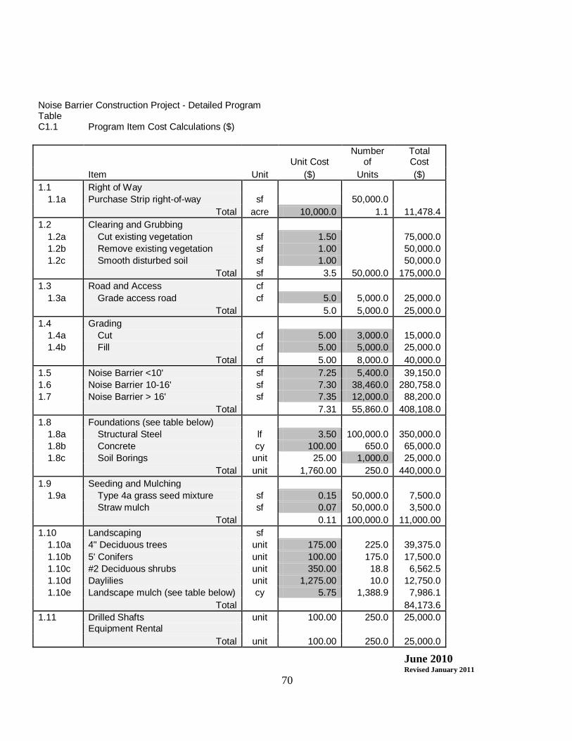
June 2010 Revised January 2011
70
Noise Barrier Construction Project - Detailed Program Table C1.1 Program Item Cost Calculations ($)
Unit Cost Number
of Total Cost
Item Unit ($) Units ($) 1.1 Right of Way
1.1a Purchase Strip right-of-way sf 50,000.0 Total acre 10,000.0 1.1 11,478.4
1.2 Clearing and Grubbing 1.2a Cut existing vegetation sf 1.50 75,000.0 1.2b Remove existing vegetation sf 1.00 50,000.0 1.2c Smooth disturbed soil sf 1.00 50,000.0 Total sf 3.5 50,000.0 175,000.0
1.3 Road and Access cf 1.3a Grade access road cf 5.0 5,000.0 25,000.0
Total 5.0 5,000.0 25,000.0 1.4 Grading
1.4a Cut cf 5.00 3,000.0 15,000.0 1.4b Fill cf 5.00 5,000.0 25,000.0
Total cf 5.00 8,000.0 40,000.0 1.5 Noise Barrier <10' sf 7.25 5,400.0 39,150.0 1.6 Noise Barrier 10-16' sf 7.30 38,460.0 280,758.0 1.7 Noise Barrier > 16' sf 7.35 12,000.0 88,200.0 Total 7.31 55,860.0 408,108.0 1.8 Foundations (see table below)
1.8a Structural Steel lf 3.50 100,000.0 350,000.0 1.8b Concrete cy 100.00 650.0 65,000.0 1.8c Soil Borings unit 25.00 1,000.0 25,000.0 Total unit 1,760.00 250.0 440,000.0
1.9 Seeding and Mulching 1.9a Type 4a grass seed mixture sf 0.15 50,000.0 7,500.0 Straw mulch sf 0.07 50,000.0 3,500.0
Total 0.11 100,000.0 11,000.00 1.10 Landscaping sf
1.10a 4" Deciduous trees unit 175.00 225.0 39,375.0 1.10b 5' Conifers unit 100.00 175.0 17,500.0 1.10c #2 Deciduous shrubs unit 350.00 18.8 6,562.5 1.10d Daylilies unit 1,275.00 10.0 12,750.0 1.10e Landscape mulch (see table below) cy 5.75 1,388.9 7,986.1 Total 84,173.6
1.11 Drilled Shafts unit 100.00 250.0 25,000.0 Equipment Rental Total unit 100.00 250.0 25,000.0

June 2010 Revised January 2011
71
Table C1.1.1 Right-of-way required Length of Barrier 5,000 Width needed for construction 10 Total Area Required 50000 Table C1.1.2 Foundation Table # Units/Foundation Unit (10' depth typical) Structural Steel lf 400 concrete cy 2.6 Table C1.1.3 Mulch Table
Depth in feet Area in sf area in sy Volume cy
Landscape Mulch cy 0.25 50000 5,555.56 1,388.89
Tables C1.1 – C1.1.3 provide the input values for the cost of the project program elements. The gray boxes are input values for the number of units needed and the unit cost.
Table C2
Derivation of Total Cost in Constant Prices ($)
Base Cost Physical Contingencies Design Supervision Total Cost
Item ($) Percent ($) Percent ($) Percent ($) ($)
2.5 Right of Way 11,478.4 5% 573.9 7% 843.7 3% 361.6 13257.6
2.6
Clearing and Grubbing 175,000.0 5% 8,750.0 7% 12862.5 3% 5512.5 202125.0
2.7 Road and Access 25,000.0 5% 1,250.0 7% 1837.5 3% 787.5 28875.0
2.8 Grading 40,000.0 5% 2,000.0 7% 2940.0 3% 1260.0 46200.0
2.9 Noise Barrier 408,108.0 5% 20,405.4 7% 29995.9 3% 12855.4 471364.7
2.12 Foundations 440,000.0 5% 22,000.0 7% 32340.0 3% 13860.0 508200.0
2.13 Seeding and Mulching 11,000.0 5% 550.0 7% 808.5 3% 346.5 12705.0
2.14 Landscaping 84,173.6 5% 4,208.7 7% 6186.8 3% 2651.5 97220.5
2.15 Drilled Shafts 25,000.0 5% 1,250.0 7% 1837.5 3% 787.5 28875.0
2.16 Total 1,219,760.0 60,414.1 88,808.7 38,060.9 1,395,565.3

June 2010 Revised January 2011
72
Input Values Table C2 gives the opportunity to capture some costs that are not captured in the previous tables. Physical contingencies represent an extra amount to account for changes in project quantities or other added expenses directly related to changes in a particular program element.

June 2010 Revised January 2011
73
Table C3 Distribution of Cost (Percent of Work Completed) Item 2005 2006 2007 2008 2009 2010 Total
3.6 Design 0% 50% 50% 0% 0% 0% 100% 3.7 Supervision 0% 0% 10% 40% 40% 10% 100% 3.8 Right of Way 25% 50% 25% 0% 0% 0% 100% 3.9 Clearing and Grubbing 0% 0% 100% 0% 0% 0% 100%
3.10 Road and Access 0% 0% 100% 0% 0% 0% 100% 3.11 Grading 0% 0% 50% 50% 0% 0% 100% 3.12 Noise Barrier 0% 0% 0% 25% 50% 25% 100% 3.15 Foundations 0% 0% 0% 50% 50% 0% 100% 3.16 Seeding and Mulching 0% 0% 0% 0% 0% 100% 100% 3.17 Landscaping 0% 0% 0% 0% 0% 100% 100% 3.18 Drilled Shafts 0% 0% 0% 50% 50% 0% 100% 3.19 Total 0%
Input Values
Table C3 provides the opportunity to identify the distribution of cost based on the percentage of work completed in each year of the project. This information is not necessary for all projects, or likely, the information is not known during project planning. The information in this table feeds into some of the following tables. Table C4
Distribution of Cost, In Constant Prices ($)
Item 2005 2006 2007 2008 2009 2010 Total
4.6 Design 0.0 44,404.3 44,404.3 0.0 0.0 0.0 88,808.70 4.7 Supervision 0.0 0.0 3,806.1 15,224.3 15,224.3 3,806.1 38,060.87
4.8 Right of Way 3,013.1 6,026.2 3,013.1 0.0 0.0 0.0 12,052.34
4.9 Clearing and Grubbing 0.0 0.0 183,750.0 0.0 0.0 0.0 183,750.00
4.10 Road and Access 0.0 0.0 26,250.0 0.0 0.0 0.0 26,250.00
4.11 Grading 0.0 0.0 21,000.0 21,000.0 0.0 0.0 42,000.00
4.12 Noise Barrier 0.0 0.0 0.0 107,128.4 214,256.7 107,128.4 428,513.40
4.15 Foundations 0.0 0.0 0.0 231,000.0 231,000.0 0.0 462,000.00
4.16 Seeding and Mulching 0.0 0.0 0.0 0.0 0.0 11,550.0 11,550.00
4.17 Landscaping 0.0 0.0 0.0 0.0 0.0 88,382.3 88,382.29
4.18 Drilled Shafts 0.0 0.0 0.0 13,125.0 13,125.0 0.0 26,250.00
4.19 Total 3,013.1 50,430.5 282,223.5 387,477.7 473,606.0 210,866.7 1,407,617.60
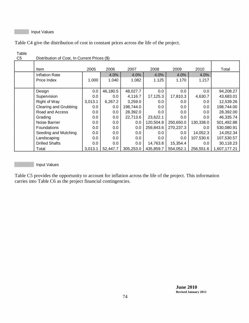
June 2010 Revised January 2011
74
Input Values Table C4 give the distribution of cost in constant prices across the life of the project. Table C5 Distribution of Cost, In Current Prices ($) Item 2005 2006 2007 2008 2009 2010 Total Inflation Rate 4.0% 4.0% 4.0% 4.0% 4.0% Price Index 1.000 1.040 1.082 1.125 1.170 1.217 Design 0.0 46,180.5 48,027.7 0.0 0.0 0.0 94,208.27 Supervision 0.0 0.0 4,116.7 17,125.3 17,810.3 4,630.7 43,683.01 Right of Way 3,013.1 6,267.2 3,259.0 0.0 0.0 0.0 12,539.26 Clearing and Grubbing 0.0 0.0 198,744.0 0.0 0.0 0.0 198,744.00 Road and Access 0.0 0.0 28,392.0 0.0 0.0 0.0 28,392.00 Grading 0.0 0.0 22,713.6 23,622.1 0.0 0.0 46,335.74 Noise Barrier 0.0 0.0 0.0 120,504.8 250,650.0 130,338.0 501,492.88 Foundations 0.0 0.0 0.0 259,843.6 270,237.3 0.0 530,080.91 Seeding and Mulching 0.0 0.0 0.0 0.0 0.0 14,052.3 14,052.34 Landscaping 0.0 0.0 0.0 0.0 0.0 107,530.6 107,530.57 Drilled Shafts 0.0 0.0 0.0 14,763.8 15,354.4 0.0 30,118.23 Total 3,013.1 52,447.7 305,253.0 435,859.7 554,052.1 256,551.6 1,607,177.21 Input Values
Table C5 provides the opportunity to account for inflation across the life of the project. This information carries into Table C6 as the project financial contingencies.

June 2010 Revised January 2011
75
Table C6 Cost Summary ($) Physical Financial Total Cost % of Summary Base Cost Contingency Contingency Current $ Total
6.5 Design 88,808.7 5,399.6 94,208.27 5.9% 6.6 Supervision 38,060.9 5,622.1 43,683.01 2.7% 6.7 Right of Way 11,478.4 573.9 486.9 12,539.3 0.8% 6.8 Clearing and Grubbing 175,000.0 8,750.0 14,994.0 198,744.00 12.4% 6.9 Road and Access 25,000.0 1,250.0 2,142.0 28,392.00 1.8% 6.1 Grading 40,000.0 2,000.0 4,335.7 46,335.74 2.9%
6.11 Noise Barrier 408,108.0 20,405.4 72,979.5 501,492.88 31.2% 6.14 Foundations 440,000.0 22,000.0 68,080.9 530,080.91 33.0% 6.15 Seeding and Mulching 11,000.0 550.0 2,502.3 14,052.34 0.9% 6.16 Landscaping 84,173.6 4,208.7 19,148.3 107,530.57 6.7% 6.17 Drilled Shafts 25,000.0 1,250.0 3,868.2 30,118.23 1.9% 6.18 Total 1,346,629.6 60,988.0 199,559.6 1,607,177.21 100.0% 6.19 Cost Distribution 6.20 as % of base cost 100.0% 4.5% 14.8% 119.3% 6.21 as % of total cost 83.8% 3.8% 12.4% 100.0% 6.22 6.23 Cost Indicators Cost 6.24 Base Cost 6.25 Construction 873,108.00 6.26 Site Preparation 240,000.00
6.27 Landscaping/Site
Finishing 95,173.61 6.28 Right of Way 11,478.42 6.29 Total Base Cost 1,219,760.03 6.30 Design + Supervision 126,869.57 6.31 Phys Contingencies 60,988.00 6.32 Financial Contingencies 199,559.61 6.33 Total Current Cost 1,607,177.21
6.34 Barrier Square Footage 55,860.00
6.35 Avg cost/sf of noise barrier ($) 28.77
6.36 Cost per Residence 14,349.80 6.37 Cost Reasonable ? Yes
Input Values
Table C6 provides a summary of total project costs and an outcome of the projects cost reasonableness based on projected costs.

June 2010 Revised January 2011
76
Appendix G: Highway Traffic-Induced Vibration There are no Federal requirements directed specifically to highway traffic induced vibration. All studies the highway agencies have done to assess the impact of operational traffic induced vibrations have shown that both measured and predicted vibration levels are less than any known criteria for structural damage to buildings. In fact, normal living activities (e.g., closing doors, walking across floors, operating appliances) within a building have been shown to create greater levels of vibration than highway traffic. Address vibration concerns on a case-by-case basis as deemed appropriate in the noise analysis or in a standalone vibration analysis report.

FHWA-PD-96-046DOT-VNTSC-FHWA-96-5
Measurement ofHighway-Related Noise
U.S. Departmentof Transportation
Federal HighwayAdministration
Cynthia S.Y. LeeGregg G. Fleming
U.S. Department of Transportation Research and Special Programs AdministrationJohn A. Volpe National Transportation Systems CenterAcoustics Facility, DTS-75Kendall SquareCambridge, MA 02142-1093
Final ReportMay 1996
This document is available to the public through the National Technical Information Service, Springfield, VA 22161
Prepared for Prepared by
U.S. Department of Transportation U.S. Department of TransportationFederal Highway Administration Research and Special Programs AdministrationOffice of Environment and Planning John A. Volpe National Transportation Systems Center
Washington, D.C. 20590 Acoustics Facility, DTS-75Kendall SquareCambridge, MA 02142-1093
FOREWORD
Noise is an important environmental consideration for highway plannersand designers. It can annoy and cause psychological or physiologicalharm, depending on frequency characteristics and loudness. The U.S.Department of Transportation and State transportation agencies arecharged with the responsibility of optimizing compatibility of highwayoperations with environmental concerns. Highway noise problems havebeen addressed by numerous investigations, including evaluations ofthe following:
(1) noise sources and highway noise reference energy mean emission levels;(2) noise impacts at receptor locations;(3) effects of site geometry, meteorology, ground surface conditions, and barriers on noise propagation; and(4) alternative methods of mitigating noise impacts.
Precise, uniform, state-of-the-art, highway traffic noise measurementprocedures for assessing impacts in the vicinity of roadways, anddesigning effective, cost-efficient noise barriers, are a recognizedneed in the highway noise community.
This report provides Federal, State, and local transportation agencieswith a set of standardized procedures for measuring and assessinghighway-related noise. It replaces "Sound Procedures for MeasuringHighway Noise" published by the FHWA in 1981.
NOTICE
This document is disseminated under the sponsorship of the Departmentof Transportation in the interest of information exchange. TheUnited States Government assumes no liability for its contents or usethereof. This report does not constitute a standard, specification,or regulation. The United States Government does not endorse products or manufactur-ers. Trade or manufacturers' names appear herein solely because theyare considered essential to the object of this document.

REPORT DOCUMENTATION PAGE Form ApprovedOMB No. 0704-0188
Public reporting burden for this collection of information is estimated to average 1 hour per response, including the time for reviewinginstructions, searching existing data sources, gathering and maintaining the data needed, and completing and reviewing the collection ofinformation. Send comments regarding this burden estimate or any other aspect of this collection of information, including suggestionsfor reducing this burden, to Washington Headquarters Services, Directorate for information Operations and Reports, 1215 Jefferson DavisHighway, Suite 1204, Arlington, VA 22202-4302, and to the Office of Management and Budget, Paperwork Reduction Project (0704-0188),Washington, DC 20503.
1. AGENCY USE ONLY (Leave blank) 2. REPORT DATE
May 1996
3. REPORT TYPE AND DATES COVERED Final ReportJanuary 1995 - May 1996
4. TITLE AND SUBTITLEMEASUREMENT OF HIGHWAY-RELATED NOISE
5. FUNDING NUMBERS
HW666/H60086. AUTHOR(S)Cynthia S.Y. Lee, Gregg G. Fleming
7. PERFORMING ORGANIZATION NAME(S) AND ADDRESS(ES)U.S. Department of TransportationResearch and Special Programs AdministrationJohn A. Volpe National Transportation Systems CenterAcoustics FacilityCambridge, MA 02142-1093
8. PERFORMING ORGANIZATION REPORT NUMBER
DOT-VNTSC-FHWA-96-5
9. SPONSORING/MONITORING AGENCY NAME(S) AND ADDRESS(ES)U.S. Department of TransportationFederal Highway AdministrationOffice of Environment and PlanningWashington, D.C. 20590
10. SPONSORING/MONITORING AGENCY REPORT NUMBER
FHWA-PD-96-046
11. SUPPLEMENTARY NOTESFHWA Program Managers: Robert E. Armstrong and Steven A. Ronning, HEP-41, Office ofEnvironment and Planning; FHWA Contacts: Howard A. Jongedyk, HNR-20, Office ofEngineering Research and Development.
12a. DISTRIBUTION/AVAILABILITY STATEMENTThis document is available to the public through the NationalTechnical Information Service, Springfield, VA 22161
12b. DISTRIBUTION CODE
13. ABSTRACT (Maximum 200 words)The U.S. Department of Transportation, Research and Special Programs Administration,John A. Volpe National Transportation Systems Center (Volpe Center), AcousticsFacility, in support of the Federal Highway Administration (FHWA), Office ofEnvironment and Planning, has developed the “Measurement of Highway-Related Noise.” This document reflects significant improvements and changes in noise measurementtechnologies that have evolved since the 1981 FHWA publication, Sound Procedures forMeasuring Highway Noise.
This report documents the recommended procedures for the measurement of (1) existingnoise; (2) vehicle noise emissions; (3) barrier insertion loss; (4) constructionequipment noise; (5) noise reduction due to buildings; and (6) occupational noiseexposure.
14. SUBJECT TERMSNoise, Highway Noise, Noise Measurement, Noise Prediction,Traffic Noise Model, FHWA TNM, Noise Barrier, Parallel NoiseBarrier, Insertion Loss, Existing Noise, Vehicle Noise Emission,REMEL, Building Noise, Construction Noise
15. NUMBER OF PAGES
189
16. PRICE CODE
17. SECURITY CLASSIFICATION OF REPORT Unclassified
18. SECURITY CLASSIFICATION OF THIS PAGE Unclassified
19. SECURITY CLASSIFICATION OF ABSTRACT Unclassified
20. LIMITATION OF ABSTRACT Unlimited
NSN 7540-01-280-5500 Standard Form 298 (Rev. 2-89)Prescribed by ANSI Std. 239-18

ii
298-102


iv
ACKNOWLEDGMENTS
The U.S. Department of Transportation, Research and Special Programs
Administration, John A. Volpe National Transportation Systems Center
(Volpe Center), Acoustics Facility, in support of the Federal HighwayAdministration (FHWA), Office of Environment and Planning, has
developed the "Measurement of Highway-Related Noise."
Major contributors of the Acoustics Facility staff members are:
Amanda S. Rapoza, Dave R. Read, and Christopher J. Roof who provided
field measurement and data reduction and analysis expertise.
Thanks also go to Rudolph Hendriks (Caltrans), Grant S. Anderson
(Harris Miller Miller & Hanson Inc.), and Frank Iacaveno (Acentech
Inc.) for their field measurement and analysis expertise and input.

v
conversion chart
vi
TABLE OF CONTENTS
Section Page
1. INTRODUCTION . . . . . . . . . . . . . . . . . . . . . 1
1.1 BACKGROUND . . . . . . . . . . . . . . . . . . . 2
1.2 OBJECTIVE . . . . . . . . . . . . . . . . . . . . 2
2. TERMINOLOGY . . . . . . . . . . . . . . . . . . . . . 5
3. INSTRUMENTATION . . . . . . . . . . . . . . . . . . . 17
3.1 ACOUSTIC INSTRUMENTATION . . . . . . . . . . . . 173.1.1 Microphone System (Microphone and
Preamplifier) . . . . . . . . . . . . . . 183.1.1.1 Microphone Type . . . . . . . . . . 193.1.1.2 Microphone Size . . . . . . . . . . 213.1.1.3 Microphone Incidence . . . . . . . 21
3.1.2 Recording System . . . . . . . . . . . . . 233.1.3 Measurement System . . . . . . . . . . . . 26
3.1.3.1 Graphic Level Recorder . . . . . . 263.1.3.2 Sound Level Meter . . . . . . . . . 273.1.3.3 One-Third Octave-Band Analyzer . . 273.1.3.4 Characteristics of the Measurement
System . . . . . . . . . . . . . . 283.1.3.4.1 Bandwidth . . . . . . . . . 283.1.3.4.2 Frequency Weighting . . . . 283.1.3.4.3 Input Gain Control . . . . . 313.1.3.4.4 Exponential Time-Averaging . 313.1.3.4.5 Temperature and Humidity
Effects . . . . . . . . . . . 323.1.4 Calibrator . . . . . . . . . . . . . . . . 333.1.5 Microphone Simulator . . . . . . . . . . . 343.1.6 Pink Noise Generator . . . . . . . . . . . 353.1.7 Windscreen . . . . . . . . . . . . . . . . 35
3.2 METEOROLOGICAL INSTRUMENTATION . . . . . . . . . 363.2.1 Anemometer . . . . . . . . . . . . . . . . 363.2.2 Thermometer, Hygrometer, and Psychrometer 38
TABLE OF CONTENTS (continued)

vii
Section Page
3.3 VEHICLE-SPEED DETECTION UNIT . . . . . . . . . . 403.3.1 Doppler-Radar Gun . . . . . . . . . . . . 403.3.2 Stopwatch . . . . . . . . . . . . . . . . 413.3.3 Light Sensor . . . . . . . . . . . . . . . 413.3.4 Pneumatic Line . . . . . . . . . . . . . . 41
3.4 TRAFFIC-COUNTING DEVICE . . . . . . . . . . . . . 423.4.1 Video Camera . . . . . . . . . . . . . . . 423.4.2 Counting Board . . . . . . . . . . . . . . 423.4.3 Pneumatic Line . . . . . . . . . . . . . . 43
3.5 SPECIAL PURPOSE INSTRUMENTATION . . . . . . . . . 433.5.1 Tachometer . . . . . . . . . . . . . . . . 433.5.2 Artificial Noise Source . . . . . . . . . 433.5.3 Noise Dosimeter . . . . . . . . . . . . . 44
3.6 SUPPORT INSTRUMENTATION . . . . . . . . . . . . . 44
3.7 MANUFACTURERS AND VENDORS . . . . . . . . . . . . 453.7.1 Acoustic Instrumentation . . . . . . . . . 45
3.7.1.1 Microphone System . . . . . . . . . 453.7.1.2 Recording System . . . . . . . . . 463.7.1.3 Measurement System . . . . . . . . 47
3.7.1.3.1 Graphic Level Recorder . . . 473.7.1.3.2 Sound Level Meter . . . . . 473.7.1.3.3 One-Third Octave-Band Analyzer48
3.7.1.4 Calibrator . . . . . . . . . . . . 493.7.1.5 Microphone Simulator . . . . . . . 493.7.1.6 Pink Noise Generator . . . . . . . 493.7.1.7 Windscreen . . . . . . . . . . . . 49
3.7.2 Meteorological Instrumentation . . . . . . 503.7.3 Vehicle-Speed Detection Unit . . . . . . . 503.7.4 Traffic-Counting Device . . . . . . . . . 51
3.7.4.1 Video Camera . . . . . . . . . . . 513.7.5 Special Purpose Instrumentation . . . . . 51
3.7.5.1 Tachometer . . . . . . . . . . . . 513.7.5.2 Artificial Noise Source . . . . . . 513.7.5.3 Noise Dosimeter . . . . . . . . . . 52
TABLE OF CONTENTS (continued)
Section Page
4. EXISTING-NOISE MEASUREMENTS IN THE VICINITY OF HIGHWAYS 53

viii
4.1 SITE SELECTION . . . . . . . . . . . . . . . . . 534.1.1 Site Characteristics . . . . . . . . . . . 53
4.1.1.1 Overall Sound Level Measurements . 534.1.1.2 Change in Sound Level Measurements 54
4.1.2 Microphone Location . . . . . . . . . . . 564.1.2.1 Reference Microphone . . . . . . . 564.1.2.2 Receiver . . . . . . . . . . . . . 57
4.2 NOISE DESCRIPTORS . . . . . . . . . . . . . . . . 58
4.3 INSTRUMENTATION . . . . . . . . . . . . . . . . . 58
4.4 SAMPLING PERIOD . . . . . . . . . . . . . . . . . 59
4.5 MEASUREMENT PROCEDURES . . . . . . . . . . . . . 60
4.6 DATA ANALYSIS . . . . . . . . . . . . . . . . . . 614.6.1 Overall Sound Level Measurement Analysis . 614.6.2 Change in Sound Level Measurement Analysis 614.6.3 Ambient Adjustments . . . . . . . . . . . 62
5. VEHICLE NOISE EMISSION LEVEL MEASUREMENTS FOR HIGHWAYNOISE PREDICTION MODELS . . . . . . . . . . . . . . . 65
5.1 SITE SELECTION . . . . . . . . . . . . . . . . . 655.1.1 Site Characteristics . . . . . . . . . . . 655.1.2 Microphone Location . . . . . . . . . . . 675.1.3 Vehicle Types . . . . . . . . . . . . . . 67
5.2 NOISE DESCRIPTORS . . . . . . . . . . . . . . . . 68
5.3 INSTRUMENTATION . . . . . . . . . . . . . . . . . 69
5.4 SAMPLING PERIOD . . . . . . . . . . . . . . . . . 695.4.1 Event Quality . . . . . . . . . . . . . . 705.4.2 Minimum Separation-Distance . . . . . . . 715.4.3 Recommended Number of Samples . . . . . . 72
TABLE OF CONTENTS (continued)
Section Page
5.5 MEASUREMENT PROCEDURES . . . . . . . . . . . . . 73
5.6 DATA ANALYSIS . . . . . . . . . . . . . . . . . . 755.6.1 Development of REMEL Regression Equations 75

ix
6. HIGHWAY BARRIER INSERTION LOSS MEASUREMENTS . . . . . 79
6.1 SITE SELECTION . . . . . . . . . . . . . . . . . 806.1.1 Site Characteristics . . . . . . . . . . . 816.1.2 Microphone Location . . . . . . . . . . . 82
6.1.2.1 Reference Microphone . . . . . . . 826.1.2.2 Receiver . . . . . . . . . . . . . 84
6.2 NOISE DESCRIPTORS . . . . . . . . . . . . . . . . 85
6.3 INSTRUMENTATION . . . . . . . . . . . . . . . . . 85
6.4 SAMPLING PERIODS . . . . . . . . . . . . . . . . 86
6.5 MEASUREMENT PROCEDURES . . . . . . . . . . . . . 866.5.1 Predicted BEFORE levels for the "Indirect
Predicted" Method . . . . . . . . . . . . 886.6 DATA ANALYSIS . . . . . . . . . . . . . . . . . . 88
6.6.1 Ambient Adjustments . . . . . . . . . . . 896.6.2 Reflections and/or Edge-Diffraction Bias
Adjustment . . . . . . . . . . . . . . . . 906.6.3 Insertion Loss . . . . . . . . . . . . . . 91
6.7 PARALLEL NOISE BARRIERS . . . . . . . . . . . . . 92
6.8 NOISE BARRIER SOUND TRANSMISSION CLASS . . . . . 95
7. CONSTRUCTION EQUIPMENT NOISE MEASUREMENTS FORHIGHWAY-RELATED PROJECTS . . . . . . . . . . . . . . . 97
7.1 SITE SELECTION . . . . . . . . . . . . . . . . . 987.1.1 Site Characteristics . . . . . . . . . . . 987.1.2 Microphone Location . . . . . . . . . . . 99
TABLE OF CONTENTS (continued)
Section Page
7.2 NOISE DESCRIPTORS . . . . . . . . . . . . . . . 100
7.3 INSTRUMENTATION . . . . . . . . . . . . . . . 100
7.4 SAMPLING PERIOD . . . . . . . . . . . . . . . . 101
7.5 MEASUREMENT PROCEDURE . . . . . . . . . . . . . 101

x
7.6 DATA ANALYSIS . . . . . . . . . . . . . . . . . 1027.6.1 Ambient Adjustments . . . . . . . . . . 1037.6.2 Determination of the Equivalent Sound Level
for Each Type of Construction Equipment 1047.6.3 Determination of the Total Equivalent Sound
Level . . . . . . . . . . . . . . . . . 105
8. BUILDING NOISE REDUCTION MEASUREMENTS IN THE VICINITYOF A HIGHWAY . . . . . . . . . . . . . . . . . . . . 107
8.1 SITE SELECTION . . . . . . . . . . . . . . . . 1078.1.1 Site Characteristics . . . . . . . . . . 107
8.1.1.2 Interior Measurements . . . . . . 1078.1.1.2 Exterior Measurements . . . . . . 108
8.1.2 Microphone Location . . . . . . . . . . 1088.1.2.1 Interior Measurements . . . . . . 1088.1.2.2 Exterior Measurements . . . . . . 109
8.1.3 Artificial Noise Source Position . . . . 110
8.2 NOISE DESCRIPTORS . . . . . . . . . . . . . . . 110
8.3 INSTRUMENTATION . . . . . . . . . . . . . . . . 111
8.4 SAMPLING PERIOD . . . . . . . . . . . . . . . . 111
8.5 MEASUREMENT PROCEDURE . . . . . . . . . . . . . 112
8.6 DATA ANALYSIS . . . . . . . . . . . . . . . . . 1138.6.1 Ambient Adjustments . . . . . . . . . . 114
TABLE OF CONTENTS (continued)
Section Page
9. HIGHWAY-RELATED OCCUPATIONAL NOISE EXPOSURE MEASUREMENTS115
9.1 SITE SELECTION . . . . . . . . . . . . . . . . 1169.1.1 Noise Dosimeter . . . . . . . . . . . . 1169.1.2 Sound Level Meter . . . . . . . . . . . 117
9.2 NOISE DESCRIPTORS . . . . . . . . . . . . . . . 117
9.3 INSTRUMENTATION . . . . . . . . . . . . . . . . 118
9.4 SAMPLING PERIOD . . . . . . . . . . . . . . . . 118

xi
9.5 MEASUREMENT PROCEDURES . . . . . . . . . . . . 118
9.6 DATA ANALYSIS . . . . . . . . . . . . . . . . . 1199.6.1 Determination of Noise Dose . . . . . . 1209.6.2 Determination of Noise Exposure . . . . 121
10. REPORT DOCUMENTATION . . . . . . . . . . . . . . . . 123
10.1 SITE SKETCHES . . . . . . . . . . . . . . . . 12310.1.1 Plan View . . . . . . . . . . . . . . . 12310.1.2 Elevation View . . . . . . . . . . . . 124
10.2 SOURCE DESCRIPTION . . . . . . . . . . . . . . 124
10.3 INSTRUMENTATION DESCRIPTION . . . . . . . . . 124
10.4 METEOROLOGICAL DATA . . . . . . . . . . . . . 124
10.5 GROUND SURFACE CHARACTERIZATION . . . . . . . 125
10.6 BARRIER CHARACTERISTICS . . . . . . . . . . . 125
10.7 MEASUREMENT PROCEDURES . . . . . . . . . . . . 125
10.8 ACOUSTICAL DATA . . . . . . . . . . . . . . . 125
10.9 INCIDENTAL OBSERVATIONS AND CONCLUSIONS . . . 125TABLE OF CONTENTS (continued)
Section Page
APPENDIX A RELATIVE HUMIDITY COMPUTATION . . . . . . 127
APPENDIX B SAMPLE DATA LOG SHEETS . . . . . . . . . . 129
APPENDIX C MINIMUM SEPARATION-DISTANCE CRITERIA FOR NOISEEMISSION LEVEL MEASUREMENTS . . . . . . . 157
APPENDIX D SAMPLE REPORT DOCUMENTATION . . . . . . . 161
REFERENCES . . . . . . . . . . . . . . . . . . . . . . . 171
INDEX . . . . . . . . . . . . . . . . . . . . . . . . . . 179

xii
LIST OF FIGURES
Figure Page
1. Graphical representation of LAE and LAFmx noisedescriptors . . . . . . . . . . . . . . . . . . . . . 14
2. Generic measurement instrumentation setup . . . . . . 17
3. Recommended microphone position relative to supportdevice . . . . . . . . . . . . . . . . . . . . . . . . 19
4. Microphone incidence . . . . . . . . . . . . . . . . . 22
5. Components of a sound level meter . . . . . . . . . . 27
6. Frequency weighting . . . . . . . . . . . . . . . . . 29
7. Exponential time-averaging . . . . . . . . . . . . . . 32
8. Site geometry . . . . . . . . . . . . . . . . . . . . 66
9. Correction for contaminating vehicles . . . . . . . . 71
10. Vehicle emissions measurement plan view . . . . . . . 73
11. Graphical form of the FHWA TNM regression equation . . 77
12. Reference microphone-position 1 . . . . . . . . . . . 83
13. Reference microphone-position 2 . . . . . . . . . . . 83
14. Receiver positions . . . . . . . . . . . . . . . . . . 84
15. Microphone positions for construction equipment noisemeasurements . . . . . . . . . . . . . . . . . . . . . 99
16. Microphone positions for building noise reductionmeasurements . . . . . . . . . . . . . . . . . . . . 109
17. Loudspeaker position . . . . . . . . . . . . . . . . 110
18. Sample plan view . . . . . . . . . . . . . . . . . . 123
LIST OF FIGURES (continued)

xiii
Figure Page
19. Sample elevation view . . . . . . . . . . . . . . . 124
20. Minimum separation distance between two similarvehicles . . . . . . . . . . . . . . . . . . . . . . 159
LIST OF TABLES
Table Page
1. Frequency weighting . . . . . . . . . . . . . . . . . 30
2. B&K Model 0237 windscreen typical response corrections 36
3. Classes of wind conditions . . . . . . . . . . . . . . 38
4. Classes of cloud cover . . . . . . . . . . . . . . . . 56
5. Sampling periods . . . . . . . . . . . . . . . . . . . 59
6. Recommended minimum number of samples . . . . . . . . 72
7. Guideline for categorizing parallel barrier sitesbased on the width-to-height ratio . . . . . . . . . . 94
8. Sample instrumentation log . . . . . . . . . . . . . 130
9. Blank instrumentation log . . . . . . . . . . . . . 131
10. Sample site data log . . . . . . . . . . . . . . . . 132
11. Blank site data log . . . . . . . . . . . . . . . . 133
12. Sample meteorological data log . . . . . . . . . . . 134
13. Blank meteorological data log . . . . . . . . . . . 135
LIST OF TABLES (continued)
Table Page
14. Existing noise measurements
xiv
Sample acoustic data log . . . . . . . . . . . . . . 136
15. Existing noise measurementsBlank acoustic data log . . . . . . . . . . . . . . 137
16. Existing noise measurementsSample vehicle data log . . . . . . . . . . . . . . 138
17. Existing noise measurementsBlank vehicle data log . . . . . . . . . . . . . . . 139
18. Vehicle emission level measurementsSample acoustic data log . . . . . . . . . . . . . . 140
19. Vehicle emission level measurementsBlank acoustic data log . . . . . . . . . . . . . . 141
20. Vehicle emission level measurementsSample vehicle data log . . . . . . . . . . . . . . 142
21. Vehicle emission level measurementsBlank vehicle data log . . . . . . . . . . . . . . . 143
22. Barrier insertion loss measurementsSample acoustic data log . . . . . . . . . . . . . . 144
23. Barrier insertion loss measurementsBlank acoustic data log . . . . . . . . . . . . . . 145
24. Barrier insertion loss measurementsSample vehicle data log . . . . . . . . . . . . . . 146
25. Barrier insertion loss measurementsBlank vehicle data log . . . . . . . . . . . . . . . 147
26. Construction equipment noise measurementsSample acoustic data log . . . . . . . . . . . . . . 148
LIST OF TABLES (continued)
Table Page
27. Construction equipment noise measurementsBlank acoustic data log . . . . . . . . . . . . . . 149

xv
28. Building noise reduction measurementsSample acoustic data log . . . . . . . . . . . . . . 150
29. Building noise reduction measurementsBlank acoustic data log . . . . . . . . . . . . . . 151
30. Building noise reduction measurementsSample vehicle data log . . . . . . . . . . . . . . 152
31. Building noise reduction measurementsBlank vehicle data log . . . . . . . . . . . . . . . 153
32. Sample occupational noise exposure data log . . . . 154
33. Blank occupational noise exposure data log . . . . . 155

1. INTRODUCTION
The U.S. Dapartment of Transportation, Research and Special Programs
Administration, John A. Volpe National Transportation Systems Center
(Volpe Center), Acoustics Facility, in support of the Federal HighwayAdministration (FHWA), Office of Environment and Planning, has
developed the “Measurement of Highway-Related Noise.” This document
reflects substantial improvements and changes in noise measurement
technologies that have evolved since the 1981 FHWA publication, Sound
Procedures for Measuring Highway Noise.
Section 1 presents a general overview, as well as an historical
perspective. Section 2 presents definitions of terminology used
throughout the document. Section 3 presents field measurement
instrumentation generalized to subsequent sections of the document.
Section 4 describes the recommended practice for performing existing-
noise measurements in the vicinity of a highway. Section 5 describes
the recommended practice for the measurement of vehicle noise
emissions for use with highway noise prediction models. Section 6
describes the procedures for the measurement of highway barrier
insertion loss. Section 7 describes the procedures for the
measurement of construction equipment noise for highway-related
projects. Section 8 describes the procedures for the measurement of
the noise reduction performance of buildings in the vicinity of a
highway. Section 9 describes the measurement of highway-related
occupational noise exposure. Section 10 details the recommended
information for properly documenting final reports prepared in
support of a highway project.
1.1 BACKGROUND
Noise is an important environmental consideration for highway
planners and designers. Transportation agencies measure different
aspects of highway noise to determine or predict community impacts
during urban planning. However, measurement instrumentation and

2
procedures have varied from program to program and agency toagency.(1) Precise, uniform, field measurement practice allows for
valid comparison of results from similar studies performed by a
variety of transportation practitioners and researchers.
Sound Procedures for Measuring Highway Noise was written over a
decade ago. Since then, substantial advancements have been made in
the methodology and technology of noise measurement, barrier analysis
and design, and noise measurement instrumentation. In addition,
highway noise modeling software has recently improved. The Federal
Highway Administration has replaced the STAndard Method In Noise
Analysis (STAMINA, Version 2.0)(2) with the FHWA Traffic Noise Model
(FHWA TNM®), Version 1.0.(3) The FHWA TNM uses a Microsoft Windows-
based interface and includes a 1994/1995 Reference Energy Mean
Emission Level (REMEL) data base,(4) as well as state-of-the-art
acoustic algorithms. Consequently, the FHWA identified the need to
develop and document a new highway-traffic noise measurement document
which reflects these recent advancements.
1.2 OBJECTIVE
The objective of this document is to provide a uniform, state-of-the-
art reference for highway noise practitioners and researchers, which
addresses measurement and analysis instrumentation, site selection,
measurement procedures, and data reduction and analysis techniques.
Each of these topics is addressed separately for each of the
following areas of concern:
(1) Existing-noise in the vicinity of a highway (Section 4);
(2) Vehicle noise emissions for use with highway noise prediction
models (Section 5); (3) Highway barrier insertion loss (Section 6);

3
(4) Construction equipment noise for highway-related projectsSection 7);
(5) Noise reduction due to buildings in the vicinity of a highway
(Section 8); and
(6) Highway-related occupational noise exposure (Section 9).

5
2. TERMINOLOGY
This section presents pertinent terminology used throughout the
document. These terms are highlighted with boldface type when they
first appear in subsequent sections. Note: Definitions are generallyconsistent with those of the American National Standards Institute
(ANSI) and References 5 through 8.
A-WEIGHTING: A frequency weighting network used to account for
changes in sensitivity as a function of frequency (See Section
3.1.3.4.2).
ABSORPTION COEFFICIENT: See Sound absorption coefficient.
ACOUSTIC ENERGY: Commonly referred to as sound energy, or just plain
energy, acoustic energy is arithmetically equivalent to 10[Sound Pressure
level (SPL)/10], where SPL is expressed in decibels re 20 :Pa.
AMBIENT NOISE: All-encompassing sound that is associated with a given
environment, excluding the analysis system’s electrical noise and the
sound source of interest.
ARTIFICIAL NOISE SOURCE: An acoustical source that is controlled in
position and calibrated as to output power, spectral content, and
directivity.
AUDIOMETRY: The measurement of human hearing acuity.
ANTI-ALIAS FILTER: A low-pass filter applied to the input signal of a
digital system prior to the digitization process. This filter,
unique to digital systems, ensures that spurious signals (alias
signals) resulting from the digitization process are not contributing

6
components of the sampled signal. An anti-alias filter must beincluded in all digital systems, prior to the analog-to-digital
conversion.
BACKGROUND NOISE: All-encompassing sound of a given environment that
includes ambient, as well as analysis system noise, excluding the
sound source of interest.
COMMUNITY-NOISE EXPOSURE LEVEL (CNEL, denoted by the symbol Lden): A
24-hour time-averaged LAE (see definition below), adjusted for
average-day sound source operations. In the case of highway noise, a
single operation is equivalent to a single vehicle pass-by. The
adjustment includes a 5-dB penalty for vehicle pass-bys occurring
between 1900 and 2200 hours, local time, and a 10-dB penalty for
those occurring between 2200 and 0700 hours, local time. The Lden
noise descriptor is used primarily in the state of California. Lden
is computed as follows:
Lden = LAE + 10*log10(Nday + 3*Neve + 10*Nnight) - 49.4 (dB)
where:
LAE = Sound exposure level in dB (See definition below);
Nday = Number of vehicle pass-bys between 0700 and 1900 hours,
local time;
Neve = Number of vehicle pass-bys between 1900 and 2200 hours,
local time;
Nnight = Number of vehicle pass-bys between 2200 and 0700 hours,
local time; and
49.4 = A normalization constant which spreads the acoustic energy
associated with highway vehicle pass-bys over a 24-hour
period, i.e., 10*log10(86,400 seconds per day) = 49.4 dB.

7
CONTAMINATION: (See Noise Contamination).
DAY-NIGHT AVERAGE SOUND LEVEL (DNL, denoted by the symbol Ldn): A 24-
hour time-averaged LAE (See definition on Page 14), adjusted for
average-day sound source operations. In the case of highway noise, a
single operation is equivalent to a single vehicle pass-by. Theadjustment includes a 10-dB penalty for vehicle pass-bys occurring
between 2200 and 0700 hours, local time. Ldn is computed as follows:
Ldn = LAE + 10*log10(Nday + Neve + 10*Nnight) - 49.4 (dB)
where:
LAE = Sound exposure level in dB (See definition on Page 14);
Nday = Number of vehicle pass-bys between 0700 and 1900 hours,
local time;
Neve = Number of vehicle pass-bys between 1900 and 2200 hours,
local time;
Nnight = Number of vehicle pass-bys between 2200 and 0700 hours,
local time; and
49.4 = A normalization constant which spreads the acoustic energy
associated with highway vehicle pass-bys over a 24-hour
period, i.e., 10*log10(86,400 seconds per day) = 49.4 dB.
DECIBEL (dB): A unit of level which denotes the ratio between two
quantities that are proportional to power; the number of decibels is
10 times the base 10 logarithm of this ratio. For the purpose of
this document, the reference level is 20 :Pa, or the threshold of
human hearing.
DIFFRACTED WAVE: A sound wave whose front has been changed in
direction by an obstacle in the propagation medium, typically airfor the purposes of this document.
8
DIVERGENCE: The spreading of sound waves from a source in a free
field environment. In the case of highway noise, two types of
divergence are common, spherical and cylindrical. Spherical
divergence is that which would occur for sound emanating from a point
source, e.g., a single vehicle pass-by. It is independent of
frequency, and is computed using a 20*log10(d1/d2) relationship. For
example, if the sound level from a point source at 15 m was 90 dB, at
30 m it would be 84 dB due to divergence, i.e., 90 + 20*log10(15/30).
Cylindrical divergence is that which would occur for sound emanating
from a line source, e.g., a single vehicle pass-by. It is
independent of frequency, and is computed using a 10*log10(d1/d2)
relationship. For example, if the sound level from a point source at
15 m was 90 dB, at 30 m it would be 87 dB due to divergence, i.e.,
90 + 10*log10(15/30).
DOPPLER EFFECT: The change in the observed frequency of a wave in a
transmission system caused by a time rate of change in the effective
length of the path of travel between the source and the point of
observation.
DYNAMIC RANGE: The difference between the highest input sound
pressure level achievable without exceeding a specified non-linearity
or distortion of the output signal, for a specified frequency range,
and the lowest input sound pressure level for which the level
linearity is within specified tolerances.
EQUIVALENT SOUND LEVEL (TEQ, denoted by the symbol LAeqT): Ten times
the base-10 logarithm of the ratio of time-mean-squared instantaneous
A-weighted sound pressure, during a stated time interval, T (where
T=t2-t1), to the square of the standard reference sound pressure.
For the purpose of this document, the reference sound pressure is 20

9
:Pa, or the threshold of human hearing. LAeqT is related to LAE bythe following equation:
LAeqT = LAE - 10*log10(t2-t1) (dB)
where:
LAE = Sound exposure level in dB (See definition on Page 14).
EXCHANGE RATE: The amount a sound level is increased or decreased to
preserve a certain noise exposure when the exposure duration is
doubled or halved. Typically, for transportation-related noise, an
exchange rate of 3 dB is used; for occupational noise exposure, 5 dB
is used.
FAR-FIELD: That portion of a point source’s sound field in which the
sound pressure level (due to this sound source) decreases by 6 dB per
doubling of distance from the source, i.e., spherical divergence; or
if the sound source is linear, then the far-field is the portion of
the sound field in which the sound pressure level decreases by 3 dB
per doubling of distance.
FREE FIELD: A sound field whose boundaries exert a negligible
influence on the sound waves. In a free-field environment, sound
spreads spherically from a source and decreases in level at a rate of
6 dB per doubling of distance from a point source, and at a rate of 3
dB per doubling of distance from a line source.
GROUND ATTENUATION: The change in sound level, either positive or
negative, due to intervening ground between source and receiver.
Ground attenuation is a relatively complex acoustic phenomenon, which
is a function of ground characteristics, source-to-receiver geometry,
and the spectral characteristics of the source. A commonly used
10
rule-of-thumb for propagation over soft ground (i.e., grass, terrain)is that ground effects will account for about 1.5 dB per doubling of
distance. However, this relationship is quite empirical and tends to
break down for distances greater than about 30 to 61 m (100 to 200
ft).
GROUND IMPEDANCE: A complex function of frequency relating the sound
transmission characteristics of a ground surface type. Measurements
to determine ground impedance must be made in accordance with the
ANSI Standard for measuring ground impedance scheduled for
publication in the second half of 1996.(50)
HARD GROUND: Any highly reflective surface in which the phase of the
sound energy is essentially preserved upon reflection; examples
includes water, asphalt and concrete.
INSERTION LOSS (IL): The difference in levels before and after
installation of a barrier, where the source, terrain, ground, and
atmospheric conditions have been judged as equivalent.
LAE: See Sound exposure level.
LAeq: See Equivalent sound level.
LAFmx and LASmx: See Maximum sound level.
Lden: See Community-noise exposure level.
Ldn: See Day-night average sound level.
L90: A statistical descriptor describing the sound level exceeded 90
percent of a measurement period.

* Rule-of-Thumb
11
LINE SOURCE: Multiple point sources moving in one direction radiating
sound cylindrically. Note: Sound levels measured from a line source
decrease at a rate of 3 dB per doubling of distance.
LOWER BOUND TO INSERTION LOSS: The value reported for insertion loss
when background levels are not measured or are too high to determinethe full attenuation potential of the barrier.
MAXIMUM SOUND LEVEL (MXFA or MXSA, denoted by the symbol LAFmx or
LASmx, respectively): The maximum, A-weighted sound level associated
with a given event (See Figure 1). Fast-scale response (LAFmx) and
slow-scale response (LASmx) characteristics effectively damp a signal
as if it were to pass through a low-pass filter with a time constant
of 125 and 1000 milliseconds, respectively. See Section 3.1.3.4.4
for a more detailed discussion of exponential time-averaging.
NEAR FIELD: The sound field (between the source and the far field).
The near field exists under optimal conditions at distances less than
four times the largest sound source dimension.
NOISE: Any unwanted sound.
NOISE BARRIER: The structure, or structure together with other
material, that potentially alters the noise at a site from a BEFORE
condition to an AFTER condition.
NOISE CONTAMINATION: Any noise event, other than that which is
intended for measurement. Contamination typically occurs when the
background noise is within 10 dB of the noise produced by the source
intended for measurement.*
12
NOISE DOSE: A measure of the noise exposure to which a person is
subjected in the workplace. For the purposes of this document, the
workplace is any highway-related environment.
NOISE REDUCTION COEFFICIENT (NRC): A single-number rating of the
sound absorption properties of a material; it is the arithmetic meanof the Sabine absorption coefficients (See below) at 250, 500, 1000,
and 2000 Hz, rounded to the nearest multiple of 0.05.
PINK NOISE: A random signal for which the spectrum density, i.e.,
narrow-band signal, varies as the inverse of frequency. In other
words, one-third octave-band spectral analysis of pink noise yields a
flat response across all frequency bands.
POINT SOURCE: Source that radiates sound spherically. Note: Sound
levels measured from a point source decrease at a rate of 6 dB per
doubling of distance.
SABINE ABSORPTION COEFFICIENT ("Sab): Absorption coefficient obtained
in a reverberation room by measuring the time rate of decay of the
sound energy density with and without a patch of the sound-absorbing
material under test laid on the floor. These measurements are
performed in accordance with the American Society of Testing and
Materials (ASTM) Standard C 423-90a.
SOFT GROUND: Any highly absorptive surface in which the phase of the
sound energy is changed upon reflection; examples include terrain
covered with dense vegetation or freshly fallen snow. (Note: at
grazing angles greater than 20 degrees, which can commonly occur at

* Rule-of-Thumb
13
short ranges, or in the case of elevated sources, soft ground becomesa good reflector and can be considered hard ground).*
SOUND ABSORPTION COEFFICIENT ("): (See also Sabine Absorption
Coefficient) The ratio of the sound energy, as a function of
frequency, absorbed by a surface, to the sound energy incident uponthat surface.
SOUND EXPOSURE LEVEL (SEL, denoted by the symbol LAE): Ten times the
logarithm to the base 10 of the ratio of a given time integral of
squared instantaneous A-weighted sound pressure to the squared
reference sound pressure of 20 :Pa, the threshold of human hearing.
The time interval must be long enough to include a majority of the
sound source’s acoustic energy. As a minimum, this interval should
encompass the 10 dB down points (See Figure 1).
Figure 1. Graphical representation of L AE and LAFmx noise descriptors.
In addition, LAE is related to LAeqT by the following equation:
LAE = LAeqT + 10*log10(t2-t1) (dB)
where LAeqT = Equivalent sound level in dB (See definition above).

14
SOUND PRESSURE LEVEL (SPL): Ten times the logarithm to the base 10 of
the ratio of the time-mean-squared pressure of a sound, in a stated
frequency band, to the square of the reference sound pressure of 20
:Pa, the threshold of human hearing.
SOUND TRANSMISSION CLASS (STC): A single-number rating used to
compare the sound insulation properties of barriers.
SPECTRUM: A signal's resolution expressed in component frequencies or
fractional octave bands.


16
3. INSTRUMENTATION
This section describes field measurement instrumentation, acoustic
and otherwise. It also includes a list of instrumentation
manufacturers.
3.1 ACOUSTIC INSTRUMENTATION
Figure 2 presents a generic, acoustic-measurement-instrumentation
setup. Subsequent subsections address individual components of thisgeneric setup.
All acoustic instrumentation should be calibrated annually by its
manufacturer, or other certified laboratory to verify accuracy.
Where applicable, all calibrations shall be traceable to the National
Institute of Standards and Technology (NIST).
Figure 2. Generic measurement instrumentation setup.
3.1.1 Microphone System (Microphone and Preamplifier)

* As previously noted, all terms defined in the Terminology section arehighlighted when they first appear in the main body of the text of thisdocument.
17
A microphone transforms sound-pressure variations into electricalsignals, that are in turn measured by instrumentation such as a sound
level meter, a one-third octave-band spectrum analyzer, or a graphic
level recorder. These electrical signals are also often recorded on
tape for later off-line analysis. Microphone characteristics are
further addressed in ANSI S1.4-1983.(9)
A compatible preamplifier, if not engineered as part of the
microphone system, should also always be used. A preamplifier
provides high-input impedance and constant, low-noise* amplification
over a wide frequency range.(10) Also, depending upon the type of
microphone being used (See Section 3.1.1.1), a preamplifier may also
provide a polarization voltage to the microphone.
The microphone system (microphone and preamplifier) should be
supported using a tripod or similar device, such as an anchoredconduit. Care should be taken to isolate the microphone system from
the support, especially if the support is made up of a metal
composite. In certain environments, the support can act as an
antenna, picking up errant radio frequency interference which can
potentially contaminate data. Common isolation methods include
encapsulating the microphone system in nonconductive material (e.g.,
nylon) prior to fastening it to the support.
In addition, it is important to ensure that the microphone system is
positioned relative to the support device, such that contamination
due to sound reflections from the support is minimized. Research has
shown that a position directly behind the support device provides for
minimum interference (See Figure 3).(11)

18
Figure 3. Recommended microphone position relative to support
device.
Once supported appropriately, the microphone should be positioned asdiscussed in Section 3.1.1.3. The microphone system should then be
connected to the measuring/recording instrumentation via an extension
cable. At least 15 m (50 ft) of cable is recommended. Thus, any
potential contamination of the measured data due to operator activity
can be minimized.
3.1.1.1 Microphone Type
Condenser (or electrostatic or capacitor) microphones are recommended
for a wide range of measurement purposes because of their high
stability, reasonably high sensitivity, excellent response at high
frequencies, and very low electrical noise characteristics. There
are two types of condenser microphones: conventional and electret.
Conventional condenser microphones characterize magnitude changes in
sound pressure in terms of variations in electrical capacitance.
Sound pressure changes incident upon the diaphragm of a microphone
change the spacing between the diaphragm and the microphone
backplate. This dynamic change in the gap between the diaphragm and
backplate translates to a change in electrical capacitance.
In the case of a conventional condenser microphone, a polarization
voltage must be applied to the backplate. Typically, a polarization
voltage of between 50 and 200 V is applied to the microphone

19
backplate by the preamplifier. Due to the requirement that apolarization voltage be supplied from a source external to the
microphone, i.e., the microphone is not a “closed” system,
measurements made with a conventional condenser microphone are often
adversely effected by atmospheric conditions, especially high
humidity. High humidity can result in condensation between the
microphone diaphragm and backplate. Condensation can cause arcing of
the polarization voltage, rendering the measured data essentially
useless.(8,12) To minimize condensation effects, the use of
dehumidifying chambers, desiccants, and nonconductive back coating,
such as quartz, can be used. Several manufacturers provide devices
to minimize this often-overlooked potential problem.
Electret condenser microphones, on the other hand, use a thin plastic
sheet with a conductive coating on one side as a backplate. This
design allows the microphone to maintain its own polarization, i.e.,
often referred to as a “pre-polarized” design.(10) "Pre-polarization"
allows the electret microphone to be essentially a “closed” system,
eliminating the potential for condensation in high-humidity
environments.
One drawback to electret microphones is they are often less sensitive
at high frequencies. In addition, there are currently no electret
microphones known to the authors which provide nearly flat response
characteristics at grazing incidence, which is the incidence of
choice for transportation-related noise measurements (See Section3.1.1.3).
3.1.1.2 Microphone Size
The diameter of a microphone diaphragm directly affects its useablefrequency range, dynamic range (or level sensitivity), and
directivity. For example, as the microphone diameter becomes
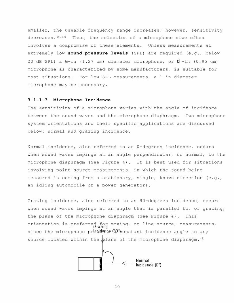
20
smaller, the useable frequency range increases; however, sensitivitydecreases.(8,13) Thus, the selection of a microphone size often
involves a compromise of these elements. Unless measurements at
extremely low sound pressure levels (SPL) are required (e.g., below
20 dB SPL) a ½-in (1.27 cm) diameter microphone, or d-in (0.95 cm)
microphone as characterized by some manufacturers, is suitable for
most situations. For low-SPL measurements, a 1-in diameter
microphone may be necessary.
3.1.1.3 Microphone Incidence
The sensitivity of a microphone varies with the angle of incidence
between the sound waves and the microphone diaphragm. Two microphone
system orientations and their specific applications are discussed
below: normal and grazing incidence.
Normal incidence, also referred to as 0-degrees incidence, occurs
when sound waves impinge at an angle perpendicular, or normal, to the
microphone diaphragm (See Figure 4). It is best used for situations
involving point-source measurements, in which the sound being
measured is coming from a stationary, single, known direction (e.g.,an idling automobile or a power generator).
Grazing incidence, also referred to as 90-degrees incidence, occurs
when sound waves impinge at an angle that is parallel to, or grazing,
the plane of the microphone diaphragm (See Figure 4). This
orientation is preferred for moving, or line-source, measurements,
since the microphone presents a constant incidence angle to any
source located within the plane of the microphone diaphragm.(8)

21
Figure 4. Microphone incidence.
Grazing incidence is commonly used for the measurement of highway,
aircraft, and guided-transit noise. If other than grazing incidence
is used for the measurement of moving noise sources, correction of
the measured data in accordance with manufacturer-published response
curves is required. This process can be quite complex because the
incidence angle is continually changing, thus requiring continuously
varying corrections. It is perfectly acceptable to position a
microphone for grazing incidence even if it has its flattest
frequency response characteristics in a normal incidence
configuration, as long as the appropriate manufacturer-published
corrections are applied, and as long as the required corrections do
not exceed certain limits.(14) If the manufacturer does not provide
the appropriate incidence corrections, testing must be performed in
accordance with ANSI S1.10-1986.(15)
For the unique situation of measuring randomly occurring sounds, such
as the case with ambient noise measurements, or existing-noise
measurements where the location of the sound source can be arbitrary,
microphone corrections should be based on random-incidence response
curves.
3.1.2 Recording System
Components of the measurement system are discussed separately in
Section 3.1.3, so as to make a distinction between the actual
recorded data, as would be heard by the human ear, and the actual
sound level data computed as a result of some form of electrical/
arithmetic process.
22
There are two basic types of tape recorders: analog and digital. Analog recorders store signals as continuous variations in the
magnetic state of the particles on the tape. Digital recorders store
signals as a combination of binary “1s” and “0s.” Most digital
recorders represent a continually varying analog level using many
discrete 16-bit words, i.e., a unique combination of 16 “1s” and
“0s.” The number of 16-bit words depends upon the sampling rate of
the particular recorder.
The sampling rate must be at least twice the highest frequency of
interest, which is often 20 kHz for transportation-related
measurements. In theory, this means that one second of continuously
varying analog data is represented by at least 40,000 discrete 16-bit
combinations of “1s” and “0s.” However, practically, due to the
design limitations on anti-alias filters (anti-alias filters are
described later in this section), a sampling rate of 44,000 to 48,000is common, i.e., 44,000 to 48,000 discrete 16-bit combinations of
“1s” and “0s.”
Not all field measurement systems will include a tape recorder. A
recorder offers the unique capability of repeated playback of the
measured noise source, thus allowing for more detailed analyses. The
electrical characteristics of a tape recorder shall conform to the
guidelines set in IEC 1265 and ANSI S1.13-1971 for frequency response
and signal-to-noise ratio.(14,16)
The advantages of modern digital over analog recorders are numerous.
Digital recorders typically have much wider frequency response
characteristics, as well as a much larger dynamic range. About the
only advantage analog recorders have is that they typically are less
expensive, although the cost difference is decreasing.

23
When selecting a specific model of tape recorder, there are threeimportant issues and/or differences associated with the use of
digital versus analog recorders that require consideration. They are
as follows:
• Anti-Alias Filters: An anti-alias filter is a low-pass filter
applied to the input signal of a digital system prior to the
digitization process. This filter, unique to digital systems,
ensures that spurious signals (alias signals) resulting from
the digitization process are not contributing components of the
sampled signal. An anti-alias filter must have attenuation
characteristics which ensure the contribution of aliased
frequency components in the output are reduced to a negligible
level.(17,18)
• System Overloads: The overload point in a digital system is a
well-defined point controlled by the maximum size of the bit-
register used in the digitization process. When the size of
the bit-register is exceeded, "hard" limiting occurs, followed
by instantaneous distortion. In most cases, the dynamic range
of a digital recorder is specified from this "hard" limiting
point, and the overload and full-scale indicators are
referenced to it.
In contrast, analog recorders have no clearly defined overload
point and generally "soft" limiting (a gradual process) begins
around 6 dB above the full scale (0 dB) on a volume unit (VU)meter, with the subsequent gradual increase in distortion.
A safety margin of at least 10 dB, and preferably 20 dB,
between the overload point and the expected maximum level of
the data to be digitally recorded, including calibration data,
should be maintained.

24
• Dynamic Range: A substantial advantage of digital recorders isthat they offer an extended dynamic range, resulting in an
extended operating range available. Dynamic range is typically
specified from the "hard" overload point, and to guard against
overload, a 10- to 20-dB safety margin is recommended, thus
reducing the effective operating range by 10 to 20 dB.
Additionally, the amplitude linearity error of a digital
recorder increases as signal levels decrease, thus, reducing
the effective operating range of the recorder. This is also
true of analog recorders.
3.1.3 Measurement System
There are three general acoustic measurement systems discussed in
this section: graphic level recorders (GLRs), sound level meters
(SLMs), and one-third octave-band analyzers.
3.1.3.1 Graphic Level Recorder
A graphic level recorder (GLR) connected to the analog output of the
measuring or recording instrumentation is typically used in the field
to provide a visual, real-time history of the measured noise level.
A GLR plot varies in level at a known, constant pen-speed rate and
response time that may be adjusted to approximate exponential time-
averaging, i.e., fast-scale and slow-scale response characteristics
(See Section 3.1.3.4.4).(10) It is valuable in visually judging
ambient levels and verifying the acoustic integrity of individual
events.
3.1.3.2 Sound Level Meter
For the purposes of all measurements discussed herein, sound level
meters (SLMs) should perform true numeric integration and averaging
in accordance with ANSI S1.4-1983.(9) Components of an SLM include

25
(See Figure 5): a microphone with preamplifier, an amplifier,frequency weighting (See Section 3.1.3.4.2), input gain control (See
Section 3.1.3.4.3), time-averaging (See Section 3.1.3.4.4), and an
output indicator or display.(8) Selection of a specific model of
sound level meter should be based upon cost and the level of accuracy
desired.
Figure 5. Components of a sound level meter.
The accuracy of an SLM is characterized by its "type." There are
three types of sound level meters available: Types 0, 1, and 2. Type
0 sound level meters are used for laboratory reference purposes,
where the highest precision is required. Type 1 sound level meters
are designed for precision field measurements and research.(9) Either
Type 1 or Type 2 sound level meters are acceptable for use in traffic
noise analyses for Federal-aid highway projects.
3.1.3.3 One-Third Octave-Band Analyzer
When the frequency characteristics of the sound source being measured
are of concern, a one-third octave-band analyzer should be employed.
In most cases, such a unit would not be employed directly in the
field, but would be used subsequent to field measurements in tandem
with tape-recorded data (See Section 3.1.2). Such units can be
employed to determine noise spectra, as well as compute various noise
descriptors, such as LAeqT and LAE. If consistency with previously
measured data is desired, one-third octave-band filters must be shown
to comply with a Type 1-D Butterworth filter, as defined in ANSI
S1.11-1986.(19) The Type 1-D Butterworth filter design has existed in

26
analyzers for decades. However, manufacturers are now providingfilter-shape algorithms which depart from the traditional Butter
worth design, and more closely resemble “ideal” filters, which allow
essentially no energy outside of the pass-band.
Use of octave-band analyzers is not precluded; however, one-third
octave-band analysis is preferred.
3.1.3.4 Characteristics of the Measurement System
3.1.3.4.1 Bandwidth
The bandwidth of a measurement instrument refers to its frequency
range of operation. Most measurement instrumentation of interest for
readers of this document will accurately measure levels in the
frequency range 20 Hz to 20 kHz, the audible range for humans.
Typically, measurement of one-third octave-band data between 50 Hz
and 10 kHz will satisfy the objectives of highway-related studies.
3.1.3.4.2 Frequency Weighting
Frequency weighting is used to account for changes in sensitivity of
the human ear as a function of frequency. Three standard weighting
networks, A, B, and C, are used to account for different responses to
sound pressure levels (See Table 1 and Figure 6).(8,20) Note: The
absence of frequency weighting is referred to as "flat" response.
C-weighting is essentially linear. B-weighting reflects the ear's
response to sounds of moderate pressure level. A-weighting reflects
the ear's response to sounds of lower pressure level.(20) A-weightingis the most widely used system for assessing transportation-related
noise. In fact, unless otherwise stated, noise descriptors for
transportation-related activity are assumed to be A-weighted. Most
SLMs and one-third octave-band analyzers offer A- and C-weighting

27
options. B-weighting has essentially become obsolete. Note: It isalso important to note that the response for the A-, B-, and C-
weighting curves are all referenced to a frequency of 1 kHz. In
other words, the weighting at 1 kHz for all three curves is zero.
Figure 6. Frequency weighting.
28
Table 1. Frequency weighting.
One-Third Octave-BandCenter Frequency
A B C
20 -50.4 -24.2 -6.2
25 -44.8 -20.5 -4.4
31.5 -39.5 -17.1 -3.0
40 -34.5 -14.1 -2.0
50 -30.3 -11.6 -1.3
63 -26.2 -9.4 -0.8
80 -22.4 -7.3 -0.5
100 -19.1 -5.6 -0.3
125 -16.2 -4.2 -0.2
160 -13.2 -2.9 -0.1
200 -10.8 -2.0 0
250 -8.7 -1.4 0
315 -6.6 -0.9 0
400 -4.8 -0.5 0
500 -3.2 -0.3 0
630 -1.9 -0.1 0
800 -0.8 0 0
1000 0 0 0
1250 0.6 0 0
1600 1.0 0 -0.1
2000 1.2 -0.1 -0.2
2500 1.3 -0.2 -0.3
3150 1.2 -0.4 -0.5
4000 1.0 -0.7 -0.8
5000 0.6 -1.2 -1.3
6300 -0.1 -1.9 -2.0
8000 -1.1 -2.9 -3.0
10000 -2.5 -4.3 -4.4
12500 -4.3 -6.1 -6.2
16000 -6.7 -8.5 -8.6
20000 -9.3 -11.2 -11.3

29
3.1.3.4.3 Input Gain Control
The input gain of a measurement system should be adjusted to provide
for maximum dynamic range while preserving a modest safety factor to
avoid overload. Dynamic range is the difference in decibels between
the maximum and minimum levels that can be accurately measured. To
avoid system overload, it is recommended that the gain be set such
that the expected maximum level of the source being measured is
between 10 and 20 decibels below overload. In the absence of a
standard that addresses linear operating ranges for general field
measurement studies, it is recommended that the linear operating
range of the measurement system is in accordance with tolerances
specified in IEC 1265, a standard specific to aircraft noise
measurement.(14)
3.1.3.4.4 Exponential Time-Averaging
Exponential time-averaging is a method of stabilizing instrumentation
response to signals with changing amplitudes over time using a low-
pass filter with a known, electrical time constant. The time
constant is defined as the time required for the output level to
reach 67 percent of the input, assuming a step-function input.
Also, the output level will typically reach 100 percent of an input-
step-function after approximately five time constants.
The exponential time-averaged output produced by the low-pass filteris a running average dominated by the most recent value but smoothed
out by the contribution of the preceding values. Two exponential
time-averaging, response settings are applicable for this document:
fast and slow, with time constants (J) of 0.125 and 1 second,
respectively (See Figure 7).

30
Fi
gure 7. Exponential time-averaging.
Slow response is typically used for measurements of sound source
levels which vary slowly as a function of time, such as aircraft.
Fast response is typically used for measuring individual highway
vehicle pass-bys (See Section 5). Slow response is recommended for
the measurement of long-term impact due to highway noise, where
impulsive noises are not dominant.
3.1.3.4.5 Temperature and Humidity Effects
Temperature and humidity can affect the sensitivity of many types of
instrumentation, including microphones and spectrum analyzers. For
example, most current-generation digital audio tape (DAT) recorders
have a built-in dew sensor which monitors condensation, and will
prevent operation under high-humidity situations. As discussed in
Section 3.1.1.1, non-electret condenser microphones are subject to
arcing under high-humidity conditions. Also, battery life is
substantially shortened when subject to prolonged low temperatures.
Manufacturers' recommendations for acceptable temperature and
humidity ranges for equipment operation should be followed.
Typically, these range from -10°C to 50°C (14°F to 122°F) and from 5
to 90 percent relative humidity.

31
3.1.4 Calibrator
An acoustic calibrator provides a means of checking the entire
acoustic instrumentation system’s (i.e., microphone, cables, and
recording instrumentation) sensitivity by producing a known sound
pressure level (referred to as the calibrator’s reference level) at aknown frequency, typically 94 or 114 dB at 1 kHz, or 124 dB at 250
Hz. The calibrator used for measurements described herein shall meet
the Type 1L performance requirements of IEC 942.(21)
Calibration of acoustic instrumentation must be performed at least at
the beginning and end of each measurement session, and before and
after any changes are made to system configuration or components. In
addition, it is strongly recommended that calibration be performed at
hourly intervals throughout the session.
The following procedure should be used to determine calibration (CAL)
adjustments prior to data analysis:
! If the final calibration of the acoustic instrumentation
differs from the initial calibration by 1 dB or less, all data
measured with that system during the time between calibrations
should be adjusted by arithmetically adding to the data the
following CAL adjustment:
CAL adjustment = reference level - [(CALINITIAL + CALFINAL) / 2]
For example:• reference level = 114.0 dB• initial calibration level = 114.1 dB• final calibration level= 114.3 dBTherefore:
CAL adjustment = 114.0-[(114.1+114.3)/2] = -0.2 dB

32
! If the final calibration of the acoustic instrumentationdiffers from the initial calibration by greater than 1 dB, all
data measured with that system during the time between
calibrations should be discarded and repeated; and the
instrumentation should be thoroughly checked.
3.1.5 Microphone Simulator
In accordance with ANSI S1.13-1971,(16) the electronic noise floor of
the entire acoustic instrumentation system should be established on a
daily basis by substituting the measurement microphone with a passive
microphone simulator (dummy microphone) and recording the noise floor
for a period of at least 30 seconds.
A dummy microphone electrically simulates the actual microphone by
providing a known fixed (i.e., passive) capacitance which is
equivalent to the minimum capacitance the microphone is capable of
providing. This allows for valid measurement of the system’s
electronic noise floor.
With the microphone removed and the simulator inserted in its place,
all input channels of the instrumentation system should be monitored
using headphones. Extraneous signals, such as radio interference or
hum, can result when the system is located near antennae, power
lines, transformers, or power generators. The system can be
especially susceptible to such interference when using long cables
which essentially act as antennae for such signals. Extraneous
signals detected must be eliminated or reduced to a negligible level,
i.e., at least 40 dB below the expected maximum level of the noise
source being measured. This can usually be accomplished by re-
orienting the instrumentation and/or cables, using shorter cable,checking and cleaning grounding contacts, or in a worst-case

33
scenario, moving the instrumentation system away from the source ofthe interference, if the position of the source is known.
3.1.6 Pink Noise Generator
The frequency response characteristics of the entire acousticinstrumentation system should be established on a daily basis by
measuring and storing 30 seconds of pink noise. Pink noise is a
random signal for which the spectrum density, i.e., narrow-band
signal, varies as the inverse of frequency. In other words, one-
third octave-band spectral analysis of pink noise yields a flat
response across all frequency bands.
3.1.7 Windscreen
Windscreens should be placed atop all microphones used in outdoor
measurements. A windscreen is a porous sphere placed atop a
microphone to reduce the effects of wind-generated noise on the
microphone diaphragm. The windscreen should be clean, dry, and in
good condition. A new windscreen is preferred.
Typically, the effect on the measured sound level due to the
insertion of a windscreen into an acoustic instrumentation system can
be neglected. As an example, Table 2 shows typical response
corrections to be applied to the measured data to account for the
insertion of a Brüel & Kjær Model 0237 windscreen, the most commonlyused windscreen for transportation-related noise measurements, into
an acoustic instrumentation system. These corrections should not be
considered typical for other model windscreens. If a manufacturer
does not provide corrections and high precision measurements are
desired, tests in an anechoic chamber would be required.
Table 2. B&K Model 0237 windscreen typical response corrections.(12)
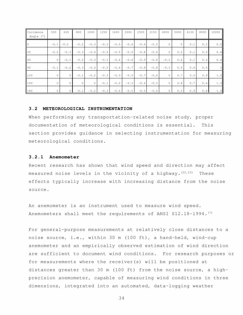
34
Incidence Angle (°)
500 630 800 1000 1250 1600 2000 2500 3150 4000 5000 6130 8000 10000
0 -0.1 -0.2 -0.2 -0.3 -0.3 -0.5 -0.6 -0.6 -0.5 0 0 0.1 0.2 0.5
30 -0.2 -0.3 -0.3 -0.4 -0.4 -0.5 -0.5 -0.8 -0.6 0 0.2 0.1 0.5 0.6
60 0 -0.1 -0.2 -0.3 -0.3 -0.4 -0.6 -0.9 -0.8 -0.2 0.4 0.1 0.4 0.6
90 -0.1 -0.2 -0.3 -0.4 -0.5 -0.6 -0.7 -0.8 -0.8 -0.3 0.5 0.6 0.5 1
120 0 0 -0.1 -0.2 -0.3 -0.3 -0.5 -0.7 -0.6 0 0.7 0.5 0.9 1.2
150 0 0 0 0 -0.1 -0.2 -0.3 -0.4 -0.3 0 0.8 0.7 0.6 1.3
180 0 0 -0.1 -0.2 -0.3 -0.4 -0.5 -0.5 -0.4 0 0.5 0.9 0.8 1.4
3.2 METEOROLOGICAL INSTRUMENTATION
When performing any transportation-related noise study, proper
documentation of meteorological conditions is essential. This
section provides guidance in selecting instrumentation for measuring
meteorological conditions.
3.2.1 Anemometer
Recent research has shown that wind speed and direction may affect
measured noise levels in the vicinity of a highway.(22,23) These
effects typically increase with increasing distance from the noise
source.
An anemometer is an instrument used to measure wind speed.
Anemometers shall meet the requirements of ANSI S12.18-1994.(7)
For general-purpose measurements at relatively close distances to a
noise source, i.e., within 30 m (100 ft), a hand-held, wind-cup
anemometer and an empirically observed estimation of wind direction
are sufficient to document wind conditions. For research purposes or
for measurements where the receiver(s) will be positioned at
distances greater than 30 m (100 ft) from the noise source, a high-
precision anemometer, capable of measuring wind conditions in three
dimensions, integrated into an automated, data-logging weather
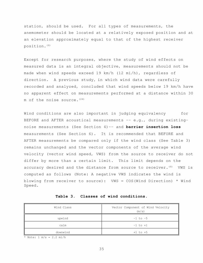
35
station, should be used. For all types of measurements, theanemometer should be located at a relatively exposed position and at
an elevation approximately equal to that of the highest receiver
position.(6)
Except for research purposes, where the study of wind effects on
measured data is an integral objective, measurements should not be
made when wind speeds exceed 19 km/h (12 mi/h), regardless of
direction. A previous study, in which wind data were carefully
recorded and analyzed, concluded that wind speeds below 19 km/h have
no apparent effect on measurements performed at a distance within 30
m of the noise source.(24)
Wind conditions are also important in judging equivalency for
BEFORE and AFTER acoustical measurements -- e.g., during existing-
noise measurements (See Section 4)-- and barrier insertion loss
measurements (See Section 6). It is recommended that BEFORE and
AFTER measurements be compared only if the wind class (See Table 3)
remains unchanged and the vector components of the average wind
velocity (vector wind speed, VWS) from the source to receiver do not
differ by more than a certain limit. This limit depends on the
accuracy desired and the distance from source to receiver.(6) VWS is
computed as follows (Note: A negative VWS indicates the wind is
blowing from receiver to source): VWS = COS(Wind Direction) * WindSpeed.
Table 3. Classes of wind conditions.
Wind Class Vector Component of Wind Velocity(m/s)
upwind -1 to -5
calm -1 to +1
downwind +1 to +5
* Note: 1 m/s = 2.2 mi/h

36
Specifically, to keep the error due to wind conditions to less than±1 dB and distances less than 70 m (230 ft), this limit should be 1.0m/s (2.2 mi/h). If it is desired to keep the acoustical error within±0.5 dB and distances less than 70 m, at least four BEFORE and fourAFTER measurements should be made within the limit of 1.0 m/s (2.2mi/h). However, these 1.0 m/s (2.2 mi/h) limits are not applicablefor a calm wind class when strong winds with a small vector componentin the direction of propagation exist. In other words, BEFORE/AFTERmeasurements in such instances should be avoided.(25)
3.2.2 Thermometer, Hygrometer, and PsychrometerA thermometer for measuring ambient temperature and a hygrometer formeasuring relative humidity should be used in conjunction with allnoise measurement studies. An alternative is to use a psychrometerwhich is capable of measuring both dry and wet bulb temperature. Dryand wet bulb temperatures can then be used to compute relativehumidity (See Appendix A).
For general purpose measurements, use of a sling psychrometer isrecommended. For research purposes, a high-precision system may beneeded, such as an automated, fast-response, data-logging weatherstation.
The thermometer or other temperature sensor should have an accuracyof ±5 percent or better at full scale. All temperature sensorsshould be shielded from direct solar radiation. In addition, avariable-height support-device may be necessary for the measurementof temperature profiles.(6)
Temperature and humidity can affect measured sound levels, typicallyto a much lesser degree than wind. In the case where the noisesource is on pavement, such as vehicle emissions (See Section 5),measurements should not be made unless the pavement is dry; emission

37
levels may be influenced by up to 2 dB by moisture on roadsurfaces.(26)
In addition, atmospheric absorption can substantially reduce measuredsound levels, especially at high frequencies in a low temperature,low-humidity environment. As such, it is important to use cautioncomparing measured data taken under substantially differenttemperature and humidity conditions, especially when the distancefrom source to receiver is quite large, or when the sound source isdominated primarily by higher frequencies. It is very difficult toprovide general rules-of-thumb, or guidance for quantifyingatmospheric absorption because of the many parameters involved;however, there are several standards which provide algorithms forcomputing such effects.(27,28,29)
3.3 VEHICLE-SPEED DETECTION UNIT
Measured sound levels of transportation-related vehicles are a directfunction of vehicle speed. This section discusses variousinstruments for measuring vehicle speed.
3.3.1 Doppler-Radar Gun
A Doppler-radar gun may be used to measure vehicle speed. When using
a radar gun, it should be placed at least 120 m (400 ft) upstream of
traffic flow, relative to the noise measurement microphone, and
directed toward the vehicles as they approach the microphone. Thisplacement has been shown to minimize effects on traffic flow
resulting from driver curiosity.(4)
The radar gun should be positioned at a distance of no greater than
10 m (31 ft) from the centerline of the path of the vehicle being
measured. This will ensure that the angle subtended by the axis of
the radar antenna and the direction of travel of the vehicle will be
less than 5 degrees, when the vehicle is at the microphone pass-by
point, assuming the 120 m offset distance mentioned above is

38
maintained. The resulting uncertainty in vehicle speed readings, dueto angular effects on Doppler accuracy, will not exceed 0.5 km/h
(0.28 mi/h) over a speed range from 15 to 110 km/h (10 to 70
mi/h).(30)
Some manufacturers now offer speed guns which are based on laser
technology. Such units would also be appropriate for determining
vehicle speed.
3.3.2 Stopwatch
A stopwatch may be used to determine vehicle speed. Cones or
observers at known distances from one another should be positioned
along the roadway. A separation distance of at least 15 m (50 ft)
should be maintained. Start/stop the stopwatch at the instants the
vehicle reaches the pass-by points. The vehicle's speed is simply
determined by dividing the distance by the measured time period. A
similar method for determining vehicle speed could also be used in
conjunction with a video camera processing a time-synchronized
display.
3.3.3 Light Sensor
Light sensors may also be used to determine vehicle speed. Position
the light sensors at known distances from one another along the
roadway. A separation distance of at least 15 m (50 ft) should
be maintained. The light sensors are triggered at the instants the
vehicle reaches the pass-by points. The triggering of the sensors
typically results in a signal being sent to some type of electronic
detector, which in turn is programmed to read and store time of day,
or compute elapsed time between pulses from a computer or other time
base. Light sensor systems are commercially available at most
electronic stores. The signal detector system may also by used to
trigger the start and stop of acoustic data collection.

39
3.3.4 Pneumatic Line
Pneumatic lines may also be positioned at known locations from one
another along the roadway to determine vehicle speed. The pressure
in the pneumatic line increases when a vehicle passes over it,
causing a mechanical switch to close. The vehicle's speed isdetermined by dividing the known distance by the measured time
period. The mechanical switches may also be used to trigger the
start and stop of acoustic data collection.
3.4 TRAFFIC-COUNTING DEVICE
For many transportation-related measurements, the collection of
traffic data, including the logging of vehicle types, as defined in
Section 5.1.3, vehicle-type volumes, and average vehicle speed may be
required for: (1) determination of site equivalence (See Existing-
Noise Measurements in Section 4 and Barrier Insertion Loss
Measurements in Section 6); or (2) input into a highway traffic noise
prediction model. This section discusses various instruments for the
counting and classification of roadway traffic, including the use of
a video camera, counting board, or pneumatic line. If none of these
instruments is available, meticulous pencil/paper tabulation should
be used.
3.4.1 Video Camera
A video camera can be used to record traffic in the field and perform
counts off-line at a later time. This approach, however, would
require strict time synchronization between the acoustic
instrumentation and the camera.
3.4.2 Counting Board
A counting board is simply a board with three or more incrementing
devices, depending on the number of vehicle types. Each device is
manually triggered to increment for a given type of vehicle pass-by.

40
3.4.3 Pneumatic Line
A pneumatic line may also be used to determine traffic counts. The
pressure in the line increases when a vehicle passes over it, causing
a mechanical switch to close. The mechanical switch triggers aninternal counting mechanism to increment. The disadvantage of using
a pneumatic line is that the specific vehicle mix, i.e., automobiles
versus trucks, as well as other vehicle types, is not preserved.
3.5 SPECIAL PURPOSE INSTRUMENTATION
3.5.1 Tachometer
A tachometer indicates or measures the revolutions per minute of arevolving shaft. A tachometer may be used to more completely
characterize noise sources, primarily for the purpose of research. A
tachometer may also be used for the measurement of special equipment,
e.g., power generators.
3.5.2 Artificial Noise Source
A fixed, artificial noise source, such as a loudspeaker, may be used
in place of the actual noise source, usually when the actual source
is not available, such as might be the case for building noise-
reduction measurements (See Section 8). Where measurements using a
loudspeaker source are to be directly compared with measurements made
using the actual noise source, a high-powered omnidirectional
loudspeaker system is recommended to properly simulate the direct and
reflected sounds of the source.(31)
The loudspeaker should produce signals of random noise filtered in
one-third octave-bands. Loudspeaker directional characteristics
shall be such that at 2000 Hz, the free-field radiated signal out to
an angle of 45 degrees shall drop no more than 6 dB relative to the

41
on-axis signal. In addition, the loudspeaker must supply sufficientoutput for measurements within the band range of 100 to 4000 Hz.(32)
3.5.3 Noise Dosimeter
In accordance with ANSI S1.25-1991(33) and the U.S. OccupationalSafety and Health Administration (OSHA), a noise dosimeter is a small
device that integrates sound pressure over time to determine a
subject’s noise dose, as a percentage of a manually set maximum
criterion determined by OSHA.(8)
Similar to a sound level meter (See Figure 5 in Section 3.1.3.2),
components of a noise dosimeter include: a microphone with
preamplifier, an amplifier, A-weighting (See Section 3.1.3.4.2), a
squaring device, slow exponential time-averaging (See Section
3.1.3.4.4), an exchange rate of 5 dB, and an output indicator or
display.
3.6 SUPPORT INSTRUMENTATION
Care should be taken to ensure that all support instrumentation is
compatible with the acoustic instrumentation. For example,
headphones should have an input impedance suitable for the recording
instrumentation's output impedance. In addition, for maximum power
transfer and minimum distortion, cables used with this equipment
should have a matching impedance. Finally, sufficient back-up
equipment, such as batteries, chargers, data sheets, floppy
diskettes, etc., should always be available.
3.7 MANUFACTURERS AND VENDORS
The following is a suggested list of sources for the instrumentation
discussed in Section 3.(34) It is not an endorsement by the FHWA, nor
is it meant to be complete, but is intended solely as a guide for
readers.
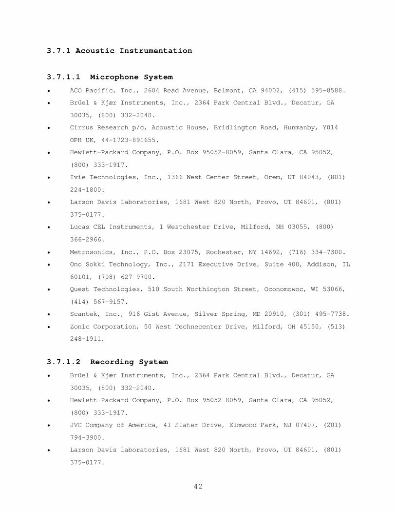
42
3.7.1 Acoustic Instrumentation
3.7.1.1 Microphone System
• ACO Pacific, Inc., 2604 Read Avenue, Belmont, CA 94002, (415) 595-8588.
• Brüel & Kjær Instruments, Inc., 2364 Park Central Blvd., Decatur, GA
30035, (800) 332-2040.
• Cirrus Research p/c, Acoustic House, Bridlington Road, Hunmanby, Y014
OPH UK, 44-1723-891655.
• Hewlett-Packard Company, P.O. Box 95052-8059, Santa Clara, CA 95052,
(800) 333-1917.
• Ivie Technologies, Inc., 1366 West Center Street, Orem, UT 84043, (801)
224-1800.
• Larson Davis Laboratories, 1681 West 820 North, Provo, UT 84601, (801)
375-0177.
• Lucas CEL Instruments, 1 Westchester Drive, Milford, NH 03055, (800)
366-2966.
• Metrosonics, Inc., P.O. Box 23075, Rochester, NY 14692, (716) 334-7300.
• Ono Sokki Technology, Inc., 2171 Executive Drive, Suite 400, Addison, IL
60101, (708) 627-9700.
• Quest Technologies, 510 South Worthington Street, Oconomowoc, WI 53066,
(414) 567-9157.
• Scantek, Inc., 916 Gist Avenue, Silver Spring, MD 20910, (301) 495-7738.
• Zonic Corporation, 50 West Technecenter Drive, Milford, OH 45150, (513)
248-1911.
3.7.1.2 Recording System
• Brüel & Kjær Instruments, Inc., 2364 Park Central Blvd., Decatur, GA
30035, (800) 332-2040.
• Hewlett-Packard Company, P.O. Box 95052-8059, Santa Clara, CA 95052,
(800) 333-1917.
• JVC Company of America, 41 Slater Drive, Elmwood Park, NJ 07407, (201)
794-3900.
• Larson Davis Laboratories, 1681 West 820 North, Provo, UT 84601, (801)
375-0177.

43
• Lucas CEL Instruments, 1 Westchester Drive, Milford, NH 03055, (800)
366-2966.
• Metrosonics, Inc., P.O. Box 23075, Rochester, NY 14692, (716) 334-7300.
• Quest Technologies, 510 South Worthington Street, Oconomowoc, WI 53066,
(800) 245-0779.
• Racal Recorders, Inc., 15375 Barranca Parkway, Suite H-101, Irvine, CA
92718, (714) 727-3444.
• Scantek, Inc., 916 Gist Avenue, Silver Spring, MD 20910, (301) 495-7738.
• Sony Electronics Inc., 3300 Zanker Road, San Jose, CA 95134, (408) 432-
1600.
• TEAC, 7733 Telegraph Road, Montebello, CA 90640, (213) 726-0303.
• Technics, Panasonic East, 50 Meadowlands Parkway, Secaucus, NJ 07094,
(201) 348-7250.
• Tritek, Inc., 155 Middlesex Turnpike, Burlington, MA 01803, (617) 272-
4550.
• Zonic Corporation, 50 West Technecenter Drive, Milford, OH 45150, (513)
248-1911.
3.7.1.3 Measurement System
3.7.1.3.1 Graphic Level Recorder
• Brüel & Kjær Instruments, Inc., 2364 Park Central Blvd., Decatur, GA
30035, (800) 332-2040.
• Hewlett-Packard Company, P.O. Box 95052-8059, Santa Clara, CA 95052,
(800) 333-1917.
3.7.1.3.2 Sound Level Meter
• ACO Pacific, Inc., 2604 Read Avenue, Belmont, CA 94002, (415) 595-8588.
• Brüel & Kjær Instruments, Inc., 2364 Park Central Blvd., Decatur, GA
30035, (800) 332-2040.
• Cirrus Research p/c, Acoustic House, Bridlington Road, Hunmanby, Y014
OPH UK, 44-1723-891655.

44
• Hewlett-Packard Company, P.O. Box 95052-8059, Santa Clara, CA 95052,
(800) 333-1917.
• Ivie Technologies, Inc., 1366 West Center Street, Orem, UT 84043, (801)
224-1800.
• Larson Davis Laboratories, 1681 West 820 North, Provo, UT 84601, (801)
375-0177.
• Lucas CEL Instruments, 1 Westchester Drive, Milford, NH 03055, (800)
366-2966.
• Metrosonics, Inc., P.O. Box 23075, Rochester, NY 14692, (716) 334-7300.
• Ono Sokki Technology, Inc., 2171 Executive Drive, Suite 400, Addison, IL
60101, (708) 627-9700.
• Quest Technologies, 510 South Worthington Street, Oconomowoc, WI 53066,
(800) 245-0779.
• Scantek, Inc., 916 Gist Avenue, Silver Spring, MD 20910, (301) 495-7738.
• Tritek, Inc., 155 Middlesex Turnpike, Burlington, MA 01803, (617) 272-
4550.
• Zonic Corporation, 50 West Technecenter Drive, Milford, OH 45150, (513)
248-1911.
3.7.1.3.3 One-Third Octave-Band Analyzer
• ACO Pacific, Inc., 2604 Read Avenue, Belmont, CA 94002, (415) 595-8588.
• Brüel & Kjær Instruments, Inc., 2364 Park Central Blvd., Decatur, GA
30035, (800) 332-2040.
• Cirrus Research p/c, Acoustic House, Bridlington Road, Hunmanby, Y014
OPH UK, 44-1723-891655.
• Computational Systems, Inc., 835 Innovation Drive, Knoxville, TN 37932,
(423) 675-2400.
• GW Instruments, 35 Medford Street, Somerville, MA 02143, (617) 625-4096.
• Hewlett-Packard Company, P.O. Box 95052-8059, Santa Clara, CA 95052,
(800) 333-1917.
• Ivie Technologies, Inc., 1366 West Center Street, Orem, UT 84043, (801)
224-1800.
• Larson Davis Laboratories, 1681 West 820 North, Provo, UT 84601, (801)
375-0177.

45
• Lucas CEL Instruments, 1 Westchester Drive, Milford, NH 03055, (800)
366-2966.
• Metrosonics, Inc., P.O. Box 23075, Rochester, NY 14692, (716) 334-7300.
• Ono Sokki Technology, Inc., 2171 Executive Drive, Suite 400, Addison, IL
60101, (708) 627-9700.
• Quest Technologies, 510 South Worthington Street, Oconomowoc, WI 53066,
(800) 245-0779.
• Scantek, Inc., 916 Gist Avenue, Silver Spring, MD 20910, (301) 495-7738.
• Tektronix, Inc., P.O. Box 500, Beaverton, OR 97077, (503) 627-7111.
• Tritek, Inc., 155 Middlesex Turnpike, Burlington, MA 01803, (617) 272-
4550.
• Zonic Corporation, 50 West Technecenter Drive, Milford, OH 45150, (513)
248-1911.
3.7.1.4 Calibrator
• Brüel & Kjær Instruments, Inc., 2364 Park Central Blvd., Decatur, GA
30035, (800) 332-2040.
• Cirrus Research p/c, Acoustic House, Bridlington Road, Hunmanby, Y014
OPH UK, 44-1723-891655.
• Larson Davis Laboratories, 1681 West 820 North, Provo, UT 84601, (801)
375-0177.
• Metrosonics, Inc., P.O. Box 23075, Rochester, NY 14692, (716) 334-7300.
• Scantek, Inc., 916 Gist Avenue, Silver Spring, MD 20910, (301) 495-7738.
3.7.1.5 Microphone Simulator
• Brüel & Kjær Instruments, Inc., 2364 Park Central Blvd., Decatur, GA
30035, (800) 332-2040.
• Larson Davis Laboratories, 1681 West 820 North, Provo, UT 84601, (801)
375-0177.
3.7.1.6 Pink Noise Generator
• Brüel & Kjær Instruments, Inc., 2364 Park Central Blvd., Decatur, GA
30035, (800) 332-2040.

46
• Ivie Technologies, Inc., 1366 West Center Street, Orem, UT 84043, (801)
224-1800.
3.7.1.7 Windscreen
• Brüel & Kjær Instruments, Inc., 2364 Park Central Blvd., Decatur, GA
30035, (800) 332-2040.
• Larson Davis Laboratories, 1681 West 820 North, Provo, UT 84601, (801)
375-0177.
3.7.2 Meteorological Instrumentation
• Climatronics Corp., 1324 Motor Parkway, Hauppauge, NY 11787, (516) 567-
7300.
• Edmund Scientific, Order Dept., Edscorp Bldg., Barrington, NJ 08007-
1380, (609) 573-6250.
• Industrial Instruments & Supplies, P.O. Box 416, County Line Industrial
Park, Southampton, PA 18966, (215) 396-0822.
• Larson Davis Laboratories, 1681 West 820 North, Provo, UT 84601, (801)
375-0177.
• R.M Young Company, 2801 Aero-Park Drive, Traverse City, MI 49686, (616)
946-3980.
• Robert E. White Instruments, 34 Commercial Wharf, Boston, MA 02110,
(617) 742-3045.
• Viking Instruments, 525 Main Street, S. Weymouth, MA 02190, (800) 325-
0360.
3.7.3 Vehicle-Speed Detection Unit
• Applied Concepts, 717 Sherman, Suite 300, Richardson, TX 75081, (214)
578-5100.
• CMI Inc., 316 East Ninth Street, Owensboro, KY 42301, (502) 685-6545.
• Decatur Electronics, Inc., 715 Bright Street, Decatur, IL 62522, (217)
428-4315.
• Kustom Signals, Inc., 9325 Pflumm, Lenexa, KS 66215, (913) 492-1400.
• Laser Technology, Inc., 7399 South Tucson Way, Garden Level B,
Inglewood, CO 80112, (303) 649-9707.

47
• Tribar Inc., 1655 Flint Road, Downsview, Ontario, Canada M3J2W8, (416)
736-9600.
3.7.4 Traffic-Counting Device
3.7.4.1 Video Camera
• HB Communications Inc., 15 Corporate Drive, P.O. Box 689, North Haven,
CT 06473-0689, (203) 234-9246.
• JVC, 14 Slater Drive, Elmwood Park, NJ 07407, (201) 794-3900.
• Panasonic, One Panasonic Way, Secaucus, NJ 07094, (201) 348-7000.
• Sony, One Sony Drive, Park Ridge, NJ 07656, (941) 768-7669.
3.7.5 Special Purpose Instrumentation
3.7.5.1 Tachometer
• Brüel & Kjær Instruments, Inc., 2364 Park Central Blvd., Decatur, GA
30035, (800) 332-2040.
• Larson Davis Laboratories, 1681 West 820 North, Provo, UT 84601, (801)
375-0177.
3.7.5.2 Artificial Noise Source
• CTS of Brownsville Inc., 3555 East 14th Street, Brownsville, TX 78521,
(210) 546-5184.
• ESS, 9613 Oates Drive, Sacramento, CA 95827.
• HB Communications Inc., 15 Corporate Drive, P.O. Box 689, North Haven,
CT 06473-0689, (203) 234-9246.
• Infinity, 9409 Owensmouth Avenue, Chatsworth, CA 91311, (818) 407-0228.
• Jamo, 425 Huehl Road, Bldg 8, Northbrook, IL 60062, (847) 498-4648.
• JBL, 240 Crossways Park W., WoodBury, NY 11797, (516) 496-3400.
• Motorola, Sheumburg, IL, (312) 397-1000.
• OHM Acoustics, 241 Taaffe Place, Brooklyn, NY 11205, (718) 783-1111.
• Panasonic, One Panasonic Way, Secaucus, NJ 07094, (201) 348-7000.

48
• Phase Technology, 6400 Yougerman Circle, Jacksonville, FL 32244, (904)
777-0700.
• Pioneer, 737 Fargo Avenue, Elk Grove Village, IL 60007, (312) 593-2960.
• Shure Brothers Inc., 222 Hartrey Avenue, Evanston, IL 60204.
• Sonance, 961 Calle Negocio, San Clemente, CA 92672, (800) 582-7777.
• VMPS, Itone, 3429 Morningside Drive, El Sobrante, CA 94803, (415) 222-
4276.
3.7.5.3 Noise Dosimeter
• Brüel & Kjær Instruments, Inc., 2364 Park Central Blvd., Decatur, GA
30035, (800) 332-2040.
• Cirrus Research p/c, Acoustic House, Bridlington Road, Hunmanby, Y014
OPH UK, 44-1723-891655.
• Larson Davis Laboratories, 1681 West 820 North, Provo, UT 84601, (801)
375-0177.
• Scantek, Inc., 916 Gist Avenue, Silver Spring, MD 20910, (301) 495-7738.

49
4. EXISTING-NOISE MEASUREMENTS IN THE VICINITY OF HIGHWAYS
This section describes recommended procedures for performing
existing-noise measurements in the vicinity of highways. Existing-
noise measurements include measurements made either prior to ahighway project, including the construction of a new highway or the
expansion of an existing one (BEFORE), measurements made subsequent
to project completion (AFTER), or measurements of both the BEFORE-
project and AFTER-project condition. This section does not address
the assessment of highway noise barrier performance, which is covered
separately in Section 6. The difference in sound levels BEFORE a
highway project is started and AFTER it is completed, combined with
the overall level associated with the completed project, gives an
indication of the expected noise impact.(35)
4.1 SITE SELECTION
Site selection should be guided by the location of noise-sensitive
receivers.
4.1.1 Site Characteristics
Site characteristics depend on the purpose of the existing-noise
measurements: (1) establishing an overall sound level for the purpose
of assessing noise impact of a nearby highway; and (2) establishing a
change in sound level prior to a highway project relative to the
sound level upon project completion.
4.1.1.1 Overall Sound Level Measurements
Land-use maps and field reconnaissance should be used to identify
potential noise-sensitive areas. Schools, hospitals, and churches
are especially sensitive to noise impacts since they require very low
levels to facilitate activity. Noise-sensitive residential areas
should also be included in a noise-impact assessment. When selecting

50
potential representative sites for overall sound level measurements,keep in mind, that the site should exhibit typical conditions (e.g.,
ambient, roadway, and meteorological) for the entire community. It
is recommended that good engineering judgment be used to select
sites, keeping in mind the objectives of the study.
4.1.1.2 Change in Sound Level Measurements
For valid comparison of BEFORE and AFTER sound levels, equivalence in
site geometry, meteorological, and traffic conditions must be
established.
Equivalence in site geometry entails similar terrain characteristics
and ground impedance within an angular sector of 120 degrees from
all receivers looking towards the noise source. For research
purposes, equivalence in ground impedance may be determined by
performing measurements in accordance with the ANSI Standard for
measuring ground impedance, scheduled for publication in the second
half of 1996.(37) For more empirical studies, or if measurements are
not feasible, then the ground for BEFORE and AFTER measurements may
be judged equivalent if general ground surface type and conditions,
e.g., surface water content, are similar.
Equivalence in meteorological conditions includes wind, temperature,
humidity, and cloud cover. Wind conditions may be judged equivalent
for BEFORE and AFTER measurements if the wind class (See Table 3 in
Section 3.2.1) remains unchanged and the vector components of the
average wind velocity from source to receiver do not differ by more
than a certain limit, which is defined as follows: (1) for an
acoustical error within ±1.0 dB and distances less than 70 m (230
ft), this limit is 1.0 m/s (2 mi/h); (2) for an acoustical error
within ±0.5 dB and distances less than 70 m (230 ft), at least fourBEFORE and AFTER measurements should be made within the limit of 1.0

51
m/s (2 mi/h). However, these 1.0 m/s limits are not applicable for acalm wind class when strong winds with a small vector component in
the direction of propagation exist. In other words, BEFORE/AFTER
measurements in such instances should be avoided.(25)
Average temperatures during BEFORE and AFTER measurements may be
judged equivalent if they are within 14° C of each other. In certain
conditions, dry air produces substantial changes in sound attenuation
at high frequencies. Therefore, for a predominantly high-frequency
source (most sound energy over 3000 Hz), the absolute humidity for
BEFORE and AFTER measurements should be similar.
The BEFORE and AFTER acoustical measurements should be made under the
same class of cloud cover, as determined from Table 4.

52
Table 4. Classes of cloud cover.(6)
Class Description
1 Heavily overcast
2 Lightly overcast (either with continuous sun or the sun obscuredintermittently by clouds 20 to 80% of the time)
3 Sunny (sun essentially unobscured by clouds at least 80% of thetime)
4 Clear night (less than 50% cloud cover)
5 Overcast night (50% or more cloud cover)
Equivalence in traffic conditions includes the volume and mix of
roadway traffic, as well as spectral content, directivity, and
spatial and temporal patterns of the individual vehicles. To acertain degree, non-equivalence in traffic conditions can be factored
out through the use of a reference microphone (See Section 4.1.2.1).
4.1.2 Microphone Location
When performing measurements to establish the change in sound level,
it is important to remember that microphone locations relative to the
sound source in the BEFORE and AFTER cases should be as close to
identical as possible.
4.1.2.1 Reference Microphone
The use of a reference microphone is strongly recommended for all
existing-noise measurements. Use of a reference microphone allows
for a calibration of measured levels, which accounts for variations
in the characteristics of the noise source, e.g., traffic speeds,
volumes, and mixes.
Typically, the reference microphone is positioned at a height of 1.5
m (5 ft), and located within 30 m (100 ft) of the centerline of the
near travel lane at a position which is minimally influenced by
ground attenuation and atmospheric effects (See Section 3.2).

53
However, the specific location of the reference microphone may bedefined by the location(s) of any noise-sensitive receiver(s) (See
Section 4.1.2.2).
4.1.2.2 Receiver
In most situations, study objectives will dictate specific microphone
locations. As such, this section presents a generic discussion of
microphone locations, and assumes no specific study objectives have
been identified.
Sometimes a single, typical residential area near the existing or
proposed highway route can be used to represent other similar areas.
If traffic conditions or topography vary greatly from one residential
area to the next, receivers at many locations may be required.
In terms of microphone height, 1.5 m (5 ft) is the preferred
position. However, microphone height(s) should be chosen to
represent all noise-sensitive receivers of interest, i.e., if
multistory structures are of interest, including microphones at
heights of 4.5 m and 7.5 m (15 ft and 25 ft) may be helpful.
Note: For receiver distances greater than 100 m (300 ft) from the
source, atmospheric effects have a much greater influence on measured
sound levels.(8,38) In such instances, precise meteorological data
will be needed to ensure BEFORE and AFTER equivalence of
meteorological conditions (See Section 3.2).
4.2 NOISE DESCRIPTORS
The equivalent sound level (LAeq) should be used to describe
continuous sounds, such as relatively dense highway traffic. The
sound exposure level (LAE), or the maximum A-weighted sound level
with fast time response characteristics (LAFmx) should be used to

54
describe the sound of single events, such as individual vehicle pass-bys. The day-night average sound level (Ldn) and the community-noise
exposure level (Lden) may be used to describe long-term noise
environments (typically greater than 24 hours), particularly for
land-use planning. Note: Once the LAeq and LAE noise descriptors are
established, other descriptors can be computed using the mathematicalrelationships presented in Section 2.
4.3 INSTRUMENTATION (See Section 3)
Microphone system (microphone and preamplifier)
Graphic level recorder (optional)
Measurement/recording instrumentation
Calibrator
Microphone simulator
Pink noise generator
Windscreen
Tripod
Cabling
Meteorological instrumentation
Vehicle-speed detection unit
Traffic-counting device4.4 SAMPLING PERIOD
Different sound sources require different sampling periods. For
multiple-source conditions, a longer sampling period is needed to
obtain a representative sample, averaged over all conditions. Typical sampling periods range from 2 to 30 minutes. In special
instances where the temporal nature is expected to vary
substantially, longer sampling periods, such as 1 hr or 24 hr, may
be necessary. Measurement repetitions at all receiver positions are
required to ensure statistical reliability of measurement results. A
minimum of 3 repetitions for like conditions is recommended, with 6
repetitions being preferred. Table 5 presents suggested measurement

55
sampling periods based on the temporal nature and the range in soundlevel fluctuations of the noise source. Guidance on judgment of the
temporal nature of the source may also be found in ANSI S1.13-1971
and ANSI S12.9-1988.(16,47)
Table 5. Sampling periods.
Temporal nature(16)Greatest anticipated range
10 dB 10-30 dB >30 dB
Steady * 2 minutes N/A N/A
Nonsteady fluctuating 5 minutes 15 minutes 30 minutes
Nonsteady intermittent For at least 10events
For at least 10events
For at least 10events
Nonsteady, impulsiveisolated bursts
For at least 10events
For at least 10events
For at least 10events
Nonsteady, impulsive-quasi-steady
3 cycles ofon/off
3 cycles ofon/off
3 cycles ofon/off
* A minimum of three repetitions is recommended, with 6 repetitions beingpreferred.
4.5 MEASUREMENT PROCEDURES
1. Prior to initial data collection, at hourly intervals
thereafter, and at the end of the measurement day, the entire
acoustic instrumentation system should be calibrated.
Meteorological conditions (wind speed and direction,
temperature, humidity, and cloud cover) should be documented
prior to data collection, at a minimum of 15-minute intervals,and whenever substantial changes in conditions are noted.
2. The electronic noise floor of the acoustic instrumentation
system should be established daily by substituting the
measurement microphone with a dummy microphone (See Section
3.1.5). The frequency response characteristics of the system
56
should also be determined on a daily basis by measuring andstoring 30 seconds of pink noise from a random-noise generator
(See Section 3.1.6).
3. Ambient levels should be measured and/or recorded by sampling
the sound level at each receiver and at the reference
microphone, with the sound source quieted or removed from the
site. A minimum of 10 seconds should be sampled. Note: If the
study sound source cannot be quieted or removed, an upper limit
to the ambient level using a statistical descriptor, such as
L90, may be used. Such upper limit ambient levels should be
reported as “assumed.” Note: Most sound level meters have the
built-in capability to determine this descriptor.
4. Sound levels should be measured and/or recorded simultaneously
with the collection of traffic data, including the logging ofvehicle types, as defined in Section 5.1.3, vehicle-type
volumes, and the average vehicle speed. It is often easier to
videotape traffic in the field and perform counts at a later
time. This approach, of course, requires strict time
synchronization between the acoustic instrumentation and the
video camera.
(Note: Appendix B provides example field-data log sheets.)
4.6 DATA ANALYSIS
4.6.1 Overall Sound Level Measurement Analysis
1. Adjust measured levels for calibration drift (See Section
3.1.4).
2. Adjust measured levels for ambient (See Section 4.6.3).

57
3. Compute the mean sound level for each receiver byarithmetically averaging the levels from individual sampling
periods.
4. Perform an assessment of the averaged sound levels based on
study objectives.
4.6.2 Change in Sound Level Measurement Analysis
1. Adjust measured levels for calibration drift (See Section
3.1.4).
2. Adjust measured levels for ambient (See Section 4.6.3).
3. For each measurement repetition of each BEFORE-AFTER receiver
pair, the noise level difference should be determined by
subtracting the difference in adjusted reference and receiver
levels for the BEFORE case from the difference in adjusted
reference and receiver levels for the AFTER case:
Differencei = (LAref - LArec) - (LBref - LBrec) (dB)
where: Differencei is the noise level difference at the ith
receiver;
LBrec and LArec are, respectively, the BEFORE and AFTER
adjusted source levels at the ith receiver; and
LBref and LAref are, respectively, the BEFORE and AFTER
adjusted reference levels.
4. Compute the mean sound level for each receiver by
arithmetically averaging the levels from individual sampling
periods.

58
5. Perform an assessment of the averaged sound levels based onstudy objectives.
4.6.3 Ambient Adjustments
If measured levels do not exceed ambient levels by 4 dB or more,i.e., they are masked, or if the levels at the reference microphone
do not exceed those at the receivers, then those data should be
omitted from data analysis.
If measured levels exceed the ambient levels by between 4 and 10
dB, and if the levels at the reference microphone exceed those at the
receivers, then correct the measured levels for ambient as follows
(Note: For source levels which exceed ambient levels by greater than
10 dB, ambient contribution becomes essentially negligible and no
correction is necessary):
(dB)
where: Ladj is the ambient-adjusted measured level;
Lc is the measured level with source and ambient combined;
and
La is the ambient level alone.
For example:
• Lc = 55.0 dB
• La = 47.0 dB
Therefore:
Ladj = 10*log10(10(0.1*55.0)-10(0.1*47.0)) = 54.3 dB


60
5. VEHICLE NOISE EMISSION LEVEL MEASUREMENTS FOR HIGHWAY NOISE
PREDICTION MODELS
This section describes recommended procedures for the measurement of
vehicle noise emission levels. Among other purposes, emission levels
are required to input user-defined vehicles in the FHWA Traffic Noise
Model (FHWA TNM®).(3) The TNM is used to predict sound levels in the
vicinity of highways and to design highway noise barriers. The
procedures described below are consistent with the methodology usedduring the development of the Reference Energy Mean Emission Level
(REMEL) Data Base for the FHWA TNM.(4,36)
5.1 SITE SELECTION
5.1.1 Site Characteristics
To minimize site specific effects associated with vehicle-noise
emission level measurements, it is recommended that between five and
ten unique sites be selected. These sites should possess thefollowing geometric characteristics:
• A flat open space free of large reflecting surfaces, such as
parked vehicles, signboards, buildings, or hillsides, located
within 30 m (100 ft) of either the vehicle path or the
microphone(s) (See Figure 8).

61
Figure 8. Site geometry.
• Ground surface within the measurement area is free of snow and
representative of acoustically hard, e.g., pavement, or
acoustically soft, e.g., grass, terrain.
• Line-of-sight from the microphone(s) to the roadway is
unobscured within an arc of 150 degrees.
• Vehicle path, i.e., roadway lane, is smooth, dry concrete,
dense-graded asphalt, or open-graded asphalt, and free of
extraneous material, such as gravel or road debris.
• A predominant, ambient level at the measurement site is low
enough to enable the measurement of uncontaminated vehicle
pass-by sound levels. Specifically, the difference between the
lowest-anticipated, vehicle pass-by, maximum A-weighted sound-
pressure level (LAFmx) and the A-weighted ambient level, as
measured at the 15-m (50-ft) microphone, should be at least 10
dB.
• Site is to be located away from known noise sources, such as
airports, construction sites, rail yards, or other heavilytraveled roadways.
62
• Site is to exhibit constant-speed roadway traffic operatingunder cruise conditions at speeds between 15 and 110 km/h (10
to 70 mi/h) and located away from intersections, lane merges or
any other features that would cause traffic to accelerate or
decelerate, unless, of course, noise emission levels are being
measured for vehicles subject to interrupted-flow traffic or
roadway grade conditions.
The above characteristics and parameters are presented for vehicle
noise emission level measurements in general; Section 5.6.1 presents
specific requirements and measurement parameters associated with
inputting user-defined vehicles in the TNM.
5.1.2 Microphone Location
The microphone system should be placed 15 m (50 ft) from the center
of the near travel lane, with the microphone diaphragm positioned for
grazing incidence, 1.5 m (5 ft) above the plane of the pavement (See
Figure 8). Additionally, systems may be optimally positioned at
other offset distances, e.g., 7.5 and 30 m (25 and 100 ft), for the
purpose of characterizing measurement-site drop-off rate.
5.1.3 Vehicle Types
Roadway vehicles are typically grouped into five acoustically
significant types, i.e., vehicles within each type exhibit
statistically similar acoustical characteristics. These vehicle
types are consistent with the FHWA TNM, and are defined as follows:
• Automobiles (A): All vehicles having two axles and four tires
and designated primarily for transportation of nine or fewer
passengers, i.e., automobiles, or for transportation of cargo,
i.e., light trucks. Generally, the gross vehicle weight is
less than 4500 kg (9900 lb).
63
• Medium Trucks (MT): All cargo vehicles having two axles and sixtires. Generally, the gross vehicle weight is greater than
4500 kg (9900 lb) but less than 12,000 kg (26,400 lb).
• Heavy Trucks (HT): All cargo vehicles having three or more
axles. Generally, the gross vehicle weight is greater than
12,000 kg (26,400 lb).
• Buses (B): All vehicles having two or three axles and
designated for transportation of nine or more passengers.
• Motorcycles (MC): All vehicles having two or three tires with
an open-air driver and/or passenger compartment.
One of the primary purposes for performing REMEL measurements is for
the purpose of characterizing user-defined vehicle types (See Section
5.6.1). Such types may include motor homes or electric cars.
5.2 NOISE DESCRIPTORS
The maximum, A-weighted sound-pressure level with fast exponential
time-averaging (LAFmx) should be used for the development of vehicle
noise emission level relationships. Additionally, spectral data,
although not required, may be useful during analysis. Specifically,
since TNM computations are performed in one-third octave-bands, it
may be helpful to verify consistency with the spectral data currently
in the model.(4)
5.3 INSTRUMENTATION (See Section 3)
Microphone system (microphone and preamplifier)
Graphic level recorder (optional)
Measurement/recording instrumentation
Calibrator
Microphone simulator
Pink noise generator
Windscreen

64
TripodCabling
Meteorological instrumentation
Vehicle-speed detection unit
5.4 SAMPLING PERIOD
The sampling period for each vehicle pass-by will vary, but should be
chosen to encompass a time period such that a minimum rise and fall
in the noise-level time-history trace of 6 dB is achieved, with 10 dB
being preferred (See Section 5.4.1). Rise and fall are defined,
respectively, as the difference between LAFmx and the minimum measured
level associated with either the start or end of a given pass-by
(whichever difference is smaller). This criterion ensures acoustic
quality of the pass-by event, and may be determined by (1) observing
the display of the sound level meter; or (2) examining the time-
history chart produced by a Graphic Level Recorder (GLR). A GLR is
the preferred instrument for establishing event quality.
5.4.1 Event QualityThe event quality for each pass-by should be determined during datameasurement and prior to data analysis. Event quality ischaracterized by three type designations (Type 2, 1, or 0).
Events with a rise and fall of the optimum 10 dB or greater aredesignated as Type 2, the highest quality event. Events with a riseand fall of between 6 and 10 dB are designated as Type 1. Events witha rise and fall of between 3 and 6 dB are designated as Type 0, andin most cases should not be used. Events with less than a 3 dB riseand fall should be discarded.
In special situations, events in which the ambient is less than 10 dBbelow the LAFmx and events designated as Type 0 may be used in the

65
analysis. More specifically, it may be necessary to relax the 10-dBambient requirement, discussed in Section 5.1.1, to 6-dB. Thissituation may occur, for example, during the measurement of low-speedautomobiles or during the measurement of hard-to-find vehicle types,e.g., buses. The LAFmx for these events may be corrected for ambientvia energy-subtraction before data analysis as follows:
(dB)
where: Ladj is the ambient-adjusted measured level;Lc is the measured level with vehicle and ambientcombined;and La is the ambient level alone.
For example:• Lc = 55.0 dB• La = 47.0 dBTherefore:Ladj = 10*log10(10(0.1*55.0)-10(0.1*47.0)) = 54.3 B
Furthermore, it may be necessary to use events designated as Type 0.
These events may be corrected only if the 10 dB-ambient requirement
is maintained, and as such, the rise and fall of these events can be
attributed entirely to nearby vehicles. This correction is to beperformed by subtracting from the measured LAFmx, the sound energy due
to “contaminating” vehicle(s) as follows:
(dB)
where: Ladj is the adjusted measured level;
Lc is the measured level with vehicle and contaminating
vehicle(s) combined;
and La is the level due to contaminating vehicle(s) alone.

66
This method is only viable if a time-history trace is available. Insuch instances, the sound due entirely to a contaminating vehicle can
be estimated through linear extrapolation (See Figure 9).
Figure 9. Correction for contaminating vehicles.
5.4.2 Minimum Separation-Distance
To ensure negligible contamination from vehicles other than the
subject vehicle, a minimum separation-distance between vehicles
should be used during the process of event selection in the field. A
previous study(35) has shown that a minimum of 120 m (400 ft) between
similar vehicles is required to insure that the contamination from
nearby vehicles is less than 0.5 dB. In the case of sequential pass-
bys of unlike vehicles, such as an automobile followed by a heavy
truck, a minimum of 300 m (985 ft) is required (See Appendix C for
further details).
5.4.3 Recommended Number of Samples
While, the number of samples is somewhat arbitrary and often a
function of budgetary constraints, a larger number of samples will
result in higher precision and a greater degree of statistical
confidence in the final emission levels. Table 6 provides, as a
function of speed, the recommended minimum number of samples. These
numbers should be considered an absolute minimum for characterizing
automobiles, medium trucks, and heavy trucks. However, for more
obscure vehicle types, such as buses, motorcycles, or motor homes, it
may not be practical to obtain such a significant number of samples.
As a point of relative comparison, 2825 autos, 765 medium trucks,

67
2986 heavy trucks, 355 buses, and 39 motorcycles were sampled for thedevelopment of the TNM.
Table 6. Recommended minimum number of samples.
Speed Minimum Number ofSamples
0-10 10
11-20 10
21-30 20
31-40 30
41-50 100
51-60 200
61-70 100
5.5 MEASUREMENT PROCEDURES
1. The instrumentation should be deployed as shown in Figure 10.
Figure 10. Vehicle emissions measurement plan view.
2. Prior to initial data collection, at hourly intervals
thereafter, and at the end of the measurement day, the entire
acoustic instrumentation system should be calibrated.
Meteorological conditions (wind speed and direction,
temperature, humidity, and cloud cover) should be documented
prior to data collection, at a minimum of 15-minute intervals,
and whenever substantial changes in conditions are noted.

68
3. The electronic noise floor of the acoustic instrumentationsystem should be established daily by substituting the
measurement microphone with a dummy microphone (See Section
3.1.5). The frequency response characteristics of the system
(if applicable) should also be determined on a daily basis by
measuring and storing 30 seconds of pink noise from a random-
noise generator (See Section 3.1.6).
4. If applicable, calibration of the Doppler radar should be
periodically checked in the field for accuracy and
functionality, using a calibrated tuning fork, and the unit's
"internal circuit test" capability, if available.
5. Ambient levels should be measured and/or recorded by sampling
the sound level at each receiver with the sound source quieted
or removed from the site. A minimum of 10 seconds should be
sampled. Note: If the study sound source cannot be quieted or
removed, an upper limit to the ambient level using a
statistical descriptor, such as L90, may be used. Such upper
limit ambient levels should be reported as “assumed.” Note:
Most sound level meters have the built-in capability to
determine this descriptor.
6. A minimum of two operators are necessary for logging all field
data: a vehicle observer and an acoustic observer. For each
pass-by event the following data should be logged: site number,event number, vehicle class, vehicle speed, maximum A-weighted
sound level (LAFmx), spectral data (if desired), meteorological
conditions, and any observed anomalies or extraneous sounds.
A potential pass-by event is identified when the vehicleobserver confirms that the minimum separation-distancecriterion is met. Note: Orange highway cones may be positioned
69
120 m (394 ft) upstream from the observers’ station to aid inidentifying potentially acceptable events.
7. After the vehicle passes the observers' station, the acoustic
observer should begin data capture.
8. After the vehicle passes the microphones and before subsequent
vehicles approach, the acoustic observer should end data
capture. Note: If the subject vehicle's speed varied by morethan ±3 km/h (2 mi/h) and/or acoustic contamination was
observed, the pass-by event should be omitted from later data
analysis.
(Note: Appendix B provides example field-data log sheets.)
5.6 DATA ANALYSIS
1. Adjust LAFmx for calibration drift (See Section 3.1.4).
2. Merge LAFmx data and corresponding vehicle information, including
speed data, into a single file for subsequent analysis, and
development of REMEL regression equations. A spreadsheet-
compatible file is recommended. Note: It is extremely
important not to exclude samples which appear to be outliers
(e.g., samples measured for extremely loud vehicles) in the
data set. Due to the nature of the field measurementprocedures, specifically the use of the minimum separation-
distance criteria, the data collected are truly representative
of a random sample.
5.6.1 Development of REMEL Regression Equations
The FHWA's Traffic Noise Model (FHWA TNM®) used for noise prediction
and barrier analysis and design allows the user to input user-defined
vehicles. However, it is anticipated that the capability to input

70
user-defined vehicles in the FHWA TNM will not be used for enteringstate-specific emission levels. Based on work performed by the Volpe
Center,(40 there is no indication of a need or justification for
developing state-specific REMELs at this time. Until the design of
highway vehicles change incrementally, or regulatory requirements
warrant lower noise emission levels, development of state-specific
REMELs is unnecessary.
However, the user-defined-vehicle capability in the FHWA TNM is
intended for describing vehicles which differ significantly from
automobiles, medium trucks, heavy trucks, buses, or motorcycles
(e.g., motor homes or electric cars). Unique vehicles should be
measured under the following reference conditions: constant-flow
roadway traffic; level grade; and dense-graded asphaltic concrete or
Portland-cement concrete.
The first step in defining a user-defined vehicle is to develop the
level-mean emission level equation. To develop the equation, the
measured LAFmx data should be regressed as a function of vehicle speed
for each vehicle type. This can be done with any commercially
available statistical analysis program. The functional form of the
regression equation is as follows:
L(s) = C + [A*log10s + B]= 10*log10[10C/10 + 10(A*logs+B)/10]= 10*log10[10C/10 + sA/1010B/10] (dB)
For example:• C = 50.128316• s = 65 km/h• A = 41.740807• B = 1.148546Therefore:L(65 km/h) = 10*log10(10(50.128/10)+65(41.741/10)*10(1.149/10)) = 76.8 dB

71
In the above equation, L(s) is expressed in terms of the logarithm tothe base 10 of the coefficient, C, (the engine/ exhaust coefficient,
which is independent of vehicle speed); and, A*log10(s) + B (the
tire/pavement-term, which increases with increasing speed, s). The
graphical form on a logarithmic plot of L(s) is illustrated in Figure
11 below.
Figure 11. Graphical form of the FHWA TNM regression equation.
The level-mean emission level equation is then adjusted upward by a
fixed value, which is a function of the relationship between the
level-mean regression and the individual LAFmx values, to develop the
energy-mean emission level equation. In previous REMEL studies, the
adjustment from level-mean to energy-mean was computed using 0.115F2,
where F is the standard error of the regression. However, due to
the potentially non-Gaussian distribution of the level-mean data
about its level-mean regression (the 0.115F2 adjustment assumes a
Gaussian distribution), the following equation is used to compute the
level-mean to energy-mean adjustment factor:
)E = 10*log10[(1/n)EREi] - (1/n)ERLi (dB)
For example:• n = 327
• EREi (i=1 to n) = RE1 + RE2 + ... + RE327 = 378.768351

72
• ERLi (i=1 to n) = RL1 + RL2 + ... + RL327 = -3.761481Therefore:
)E = 10*log10[(1/n)ERE] - (1/n)ERL = 0.649762
In the above, the RLi values represent the level residuals, which are
equivalent to the value of each data point, i, at its corresponding
speed, s, minus the value of regression at s; REi values represent
the energy residuals, which are equivalent to
; and n represents the total number of data samples.
This )E adjustment is then added to both the engine/exhaust term and
the tire/pavement term of the L(s) equation, i.e., the C and B
coefficients, as follows:
LE(s) = 10*log10[10(C+)E)/10 + sA/1010(B+)E)/10] (dB)
From the above energy-mean emission-level regression equation, four
input parameters are required to specify a user-defined vehicle type
in the FHWA TNM: (1) a minimum level (the C coefficient plus )E);
(2) a reference level (the emission level at 80 km/h or 50 mi/h); (3)
the slope (the A coefficient); and (4) a like vehicle type. A like
vehicle type is the FHWA TNM vehicle type to which the user-defined
type is most similar. In determining a like vehicle type, the
factors to be considered are listed in order of importance as
follows: estimated subsource heights; estimated acceleration
characteristics; and estimated, one-third octave-band frequency
spectrum.(3,4)
6. HIGHWAY BARRIER INSERTION LOSS MEASUREMENTS
This section describes recommended procedures for the measurement of
highway noise barrier insertion loss. Insertion loss is defined as
the difference in sound level at a receiver location with and without
73
the presence of a noise barrier, assuming no change in the soundlevel of the source.
The procedures described in this section are in accordance with ANSI
S12.8-1987,(6) which provides three methods to determine the field
insertion loss of noise barriers: (1) "direct" BEFORE/AFTER
measurement; (2) "indirect" BEFORE measurement at an equivalent site;
and (3) "indirect" predictions of BEFORE levels.
The "direct" BEFORE/AFTER method requires performing measurements at
a site before the barrier has been constructed to determine "BEFORE"
levels, and another set of measurements at the same site after
construction to determine "AFTER" levels. The advantage of using
this method is that it insures identical site geometric
characteristics. However, the disadvantages are that equivalent
meteorological and traffic conditions may not be reproducible.
The "indirect" BEFORE method requires performing measurements at a
site with a barrier to determine "AFTER" levels, and another set of
measurements at an "equivalent" site without a barrier to determine
equivalent "BEFORE" levels.
A site may be judged equivalent if geometric, atmospheric, and
traffic conditions are determined to be essentially identical for the
BEFORE case as compared with the AFTER case. Geometric equivalence
refers to the terrain characteristics and ground impedance at thesite. Atmospheric equivalence refers to temperature, humidity, and
wind speed and direction (See Section 6.1.1). Traffic equivalence
refers to vehicle type and mix.
The BEFORE and AFTER cases for the “indirect” BEFORE method should be
studied simultaneously, if possible. In other words, the ideal
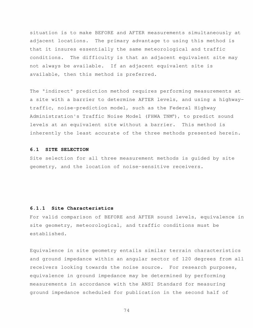
74
situation is to make BEFORE and AFTER measurements simultaneously atadjacent locations. The primary advantage to using this method is
that it insures essentially the same meteorological and traffic
conditions. The difficulty is that an adjacent equivalent site may
not always be available. If an adjacent equivalent site is
available, then this method is preferred.
The "indirect" prediction method requires performing measurements at
a site with a barrier to determine AFTER levels, and using a highway-
traffic, noise-prediction model, such as the Federal Highway
Administration's Traffic Noise Model (FHWA TNM®), to predict sound
levels at an equivalent site without a barrier. This method is
inherently the least accurate of the three methods presented herein.
6.1 SITE SELECTION
Site selection for all three measurement methods is guided by site
geometry, and the location of noise-sensitive receivers.
6.1.1 Site Characteristics
For valid comparison of BEFORE and AFTER sound levels, equivalence in
site geometry, meteorological, and traffic conditions must be
established.
Equivalence in site geometry entails similar terrain characteristics
and ground impedance within an angular sector of 120 degrees from all
receivers looking towards the noise source. For research purposes,
equivalence in ground impedance may be determined by performing
measurements in accordance with the ANSI Standard for measuring
ground impedance scheduled for publication in the second half of

75
1996.(37) For more empirical studies, or if measurements are notfeasible, then the ground for BEFORE and AFTER measurements may be
judged equivalent if general ground surface type and conditions,
e.g., surface water content, are similar.
Equivalence in meteorological conditions includes wind, temperature,
humidity, and cloud cover. Wind conditions may be judged equivalent
for BEFORE and AFTER measurements if the wind class (See Table 3 in
Section 3.2.1) remains unchanged and the vector components of the
average wind velocity from source to receiver do not differ by more
than a certain limit, which is defined as follows: (1) for an
acoustical error within ±1.0 dB and distances less than 70 m (230
ft), this limit is 1.0 m/s (2 mi/h); (2) for an acoustical error
within ±0.5 dB and distances less than 70 m (230 ft), at least four
BEFORE and AFTER measurements should be made within the limit of 1.0
m/s (2 mi/h). However, these 1.0 m/s limits is not applicable for a
calm wind class when strong winds with a small vector component in
the direction of propagation exist. In other words, BEFORE/AFTER
measurements in such instances should be avoided.(25)
Average temperatures during BEFORE and AFTER measurements may be
judged equivalent if they are within 14° C of each other. Also, in
certain conditions, dry air produces substantial changes in sound
attenuation at high frequencies. Therefore, for a predominantly
high-frequency source (most sound energy over 3000 Hz), the absolute
humidity for BEFORE and AFTER measurements should be similar.
The BEFORE and AFTER acoustical measurements should be made under the
same class of cloud cover (See Table 4 in Section 4.1.1.2).
Equivalence in traffic conditions includes the number and mix of
roadway traffic, as well as spectral content, directivity, and

76
spatial and temporal patterns of the individual vehicles. To acertain degree, non-equivalence in traffic conditions can be factored
out through the use of a reference microphone (See Section 6.1.2.1).
6.1.2 Microphone Location
6.1.2.1 Reference Microphone
The use of a reference microphone is strongly recommended for all
barrier insertion loss measurements. Use of a reference microphoneallows for a calibration of measured levels, which accounts for
variations in the characteristics of the noise source, e.g., traffic
speeds, volumes, and mixes. In most cases, a reference microphone is
placed between the noise source and other measurement microphones at
a height of 1.5 m (5 ft) directly above the barrier (See Figure 12),
and at a distance from the sound source sufficient to minimize near-
field effects. Typically, a minimum, standard distance of 15 m (50
ft) from the noise source is used. If the barrier is located less
than 15 m from the source, the reference microphone should be placed
at a distance of 15 m from the noise source, but at a height such
that the line of sight between the microphone and the ground plane
beneath the source is at least 10° (See Figure 13). This location
should remain the same for all measurements, including measurements
at the equivalent site, where the barrier is not present.
Figure 12. Reference microphone-position 1.
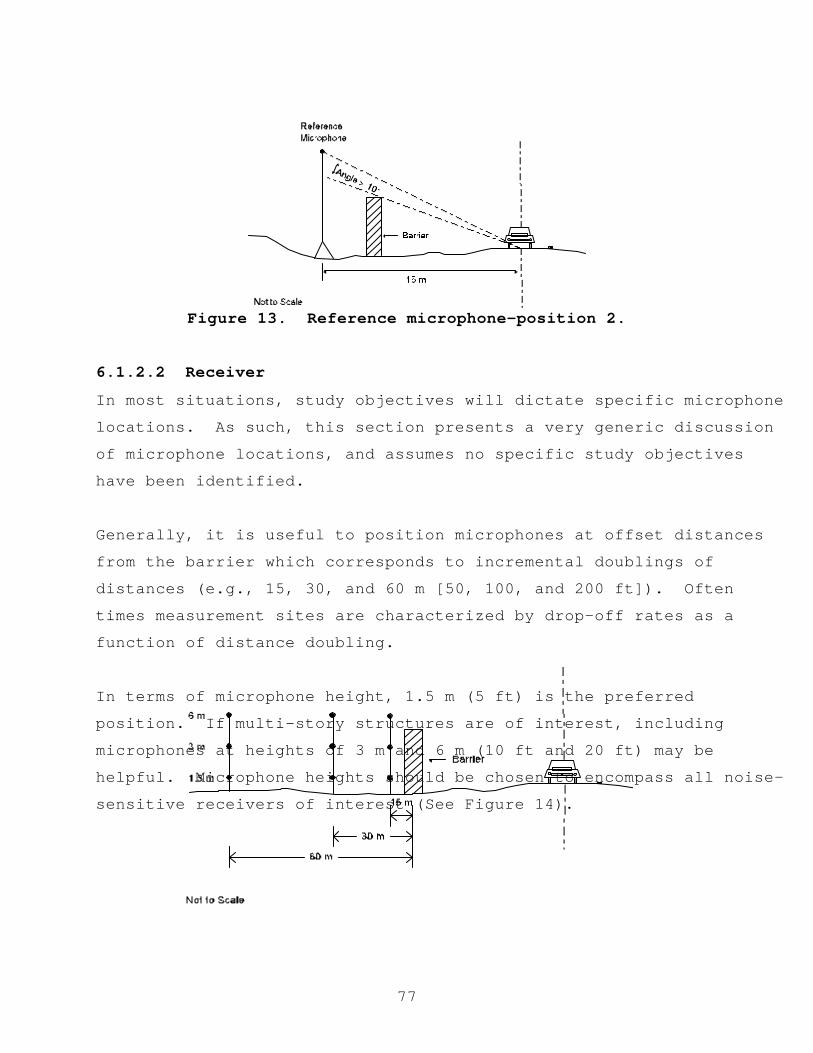
77
Figure 13. Reference microphone-position 2.
6.1.2.2 Receiver
In most situations, study objectives will dictate specific microphone
locations. As such, this section presents a very generic discussion
of microphone locations, and assumes no specific study objectives
have been identified.
Generally, it is useful to position microphones at offset distances
from the barrier which corresponds to incremental doublings of
distances (e.g., 15, 30, and 60 m [50, 100, and 200 ft]). Often
times measurement sites are characterized by drop-off rates as a
function of distance doubling.
In terms of microphone height, 1.5 m (5 ft) is the preferred
position. If multi-story structures are of interest, including
microphones at heights of 3 m and 6 m (10 ft and 20 ft) may be
helpful. Microphone heights should be chosen to encompass all noise-
sensitive receivers of interest (See Figure 14).

78
Figure 14. Receiver positions.
For the purpose of determining barrier insertion loss, it is
important to remember that microphone locations relative to the sound
source in the BEFORE and AFTER cases must be identical. There may be
instances when receivers are placed on the lawns of homes within the
community adjacent to a noise barrier.
Note: For receiver distances greater than 100 m (300 ft) from the
source, atmospheric effects have a much greater influence on measured
sound levels.(8,38) In such instances, precise meteorological data
will be needed to ensure BEFORE and AFTER equivalence of the
meteorological conditions (See Section 3.2).
6.2 NOISE DESCRIPTORS
The equivalent sound level (LAeq) should be used to describe
continuous sounds, such as relatively dense highway traffic. The
sound exposure level (LAE), or the maximum A-weighted sound level
with fast time response characteristics (LAFmx), should be used to
describe the sound of single events, such as individual vehicle pass-
bys. The day-night average sound level (Ldn) and the community-noise
exposure level (Lden) may be used to describe long-term noise
environments (typically greater than 24 hours), particularly for
land-use planning. Note: Once the LAeq and LAE noise descriptors are
established, other descriptors can be computed using the mathematical
relationships presented in Section 2.
6.3 INSTRUMENTATION (See Section 3)

79
Microphone system (microphone and preamplifier)Graphic level recorder (optional)
Measurement/recording instrumentation
Calibrator
Microphone simulator
Pink noise generator
Windscreen
Tripod
Cabling
Meteorological instrumentation
Vehicle-speed detection unit
Traffic-counting device
6.4 SAMPLING PERIODS
Different sound sources require different sampling periods. For
multiple-source conditions, a longer sampling period is needed to
obtain a representative sample, averaged over all conditions.
Typical sampling periods are 15 minutes, 1 hr and 24 hr. Measurement
repetitions at all receiver positions are required to ensure
statistical reliability of measurement results. A minimum of three
repetitions for like conditions is recommended, with six repetitions
being preferred. Table 5 in Section 4.4 presents suggested
measurement sampling periods based on the temporal nature and the
range in sound level fluctuations of the noise source. Guidance on
judgment of the temporal nature of the source may also be found in
ANSI S1.13-1971 and ANSI S12.9-1988.(16,47)
6.5 MEASUREMENT PROCEDURES
The following steps apply for all methods except the BEFORE
predictions for the "indirect predicted" method, which is discussed
separately in Section 6.5.1.

80
1. Prior to initial data collection, at hourly intervalsthereafter, and at the end of the measurement day, the entire
acoustic instrumentation system should be calibrated.
Meteorological conditions (wind speed and direction,
temperature, humidity, and cloud cover) should be documented
prior to data collection, at a minimum of 15-minute intervals,
and whenever substantial changes in conditions are noted.
2. The electronic noise floor of the acoustic instrumentation
system should be established daily by substituting the
measurement microphone with a dummy microphone (See Section
3.1.5). The frequency response characteristics of the system
should also be determined on a daily basis by measuring and
storing 30 seconds of pink noise from a random-noise generator
(See Section 3.1.6)
3. Ambient levels should be measured and/or recorded by sampling
the sound level at each receiver and at the reference
microphone with the sound source quieted or removed from the
site. A minimum of 10 seconds should be sampled. Note: If the
study sound source cannot be quieted or removed, an upper limit
to the ambient level using a statistical descriptor, such as
L90,may be used. Such upper limit ambient levels should be
reported as “assumed.” Note: Most sound level meters have the
built-in capability to determine this descriptor.
4. Sound levels should be measured and/or recorded simultaneously
with the collection of traffic data, including the logging of
vehicle types, as defined in Section 5.1.3, vehicle-type
volumes, and the average vehicle speed. It is often easier to
videotape traffic in the field and perform counts at a later
time. This approach, of course, requires strict time

81
synchronization between the acoustic instrumentation and thevideo camera.
(Note: Appendix B provides example field-data log sheets.)
6.5.1 Predicted BEFORE levels for the "Indirect Predicted"
Method
1. Perform the data collection for the AFTER case according to
Section 6.5.
2. Using the measured traffic data and the observed site data,
input the necessary information into a highway-noise prediction
model, such as the FHWA TNM, to compute BEFORE levels at the
reference position and at each receiver position. It is
possible that modeled levels at the reference position may
differ substantially in the BEFORE case, as compared with the
measured AFTER case. In such instances, the difference
observed at the reference microphone shall be used as a
calibration factor for all other measurement positions (See
Section 6.6).
6.6 DATA ANALYSIS
1. For valid comparisons of BEFORE and AFTER measured levels, the
equivalence of meteorological conditions, i.e., wind,
temperature, humidity, and cloud cover, should be established
(See Section 6.1.1). It is assumed that equivalence of site
parameters, such as terrain characteristics and ground
impedance, were established prior to performing measurements.
Sampling periods in which equivalence cannot be established
should be excluded from subsequent analysis.
82
2. Adjust measured levels for calibration drift (See Section3.1.4).
3. Adjust measured levels for ambient (See Section 6.6.1).
4. Adjust measured levels for the reflection and/or edge-
diffraction bias adjustment (See Section 6.6.2).
5. Compute the barrier insertion loss or lower-bound to insertion
loss for each source-receiver pair (See Section 6.6.3).
6. Compute the mean barrier insertion loss by arithmetically
averaging the insertion loss values from individual sampling
periods.
7. Perform an assessment of mean insertion loss values based onstudy objectives.
6.6.1 Ambient Adjustments
If measured levels do not exceed ambient levels by 4 dB or more, orif the levels at the reference microphone do not exceed those at the
receivers, then the barrier insertion loss cannot be determined.
If measured levels exceed the ambient levels by between 4 and 10 dB,
and if the levels at the reference microphone exceed those at the
receivers, then measured levels must be corrected for ambient as
follows (Note: For sound levels which exceed ambient levels by
greater than 10 dB, ambient contribution becomes essentially
negligible and no correction is necessary):
(dB)
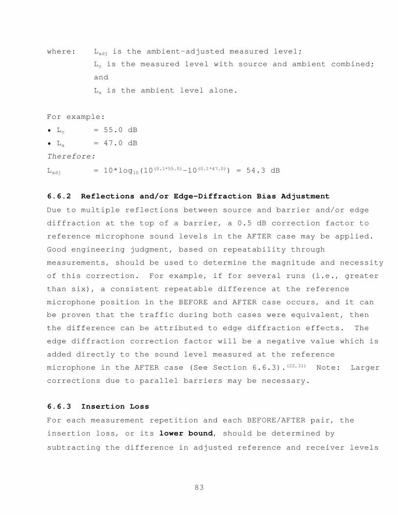
83
where: Ladj is the ambient-adjusted measured level;Lc is the measured level with source and ambient combined;
and
La is the ambient level alone.
For example:
• Lc = 55.0 dB
• La = 47.0 dB
Therefore:
Ladj = 10*log10(10(0.1*55.0)-10(0.1*47.0)) = 54.3 dB
6.6.2 Reflections and/or Edge-Diffraction Bias Adjustment
Due to multiple reflections between source and barrier and/or edge
diffraction at the top of a barrier, a 0.5 dB correction factor to
reference microphone sound levels in the AFTER case may be applied.
Good engineering judgment, based on repeatability through
measurements, should be used to determine the magnitude and necessity
of this correction. For example, if for several runs (i.e., greater
than six), a consistent repeatable difference at the reference
microphone position in the BEFORE and AFTER case occurs, and it canbe proven that the traffic during both cases were equivalent, then
the difference can be attributed to edge diffraction effects. The
edge diffraction correction factor will be a negative value which is
added directly to the sound level measured at the reference
microphone in the AFTER case (See Section 6.6.3).(22,31) Note: Larger
corrections due to parallel barriers may be necessary.
6.6.3 Insertion Loss
For each measurement repetition and each BEFORE/AFTER pair, the
insertion loss, or its lower bound, should be determined by
subtracting the difference in adjusted reference and receiver levels

* Rule-of-Thumb
84
for the BEFORE case from the difference in adjusted reference andreceiver levels for the AFTER case:
ILi = (LAref + Ledge - LArec) - (LBref - LBrec) (dB)
where: ILi is the insertion loss at the ith receiver;LBref and LAref are, respectively, the BEFORE and AFTERadjusted reference levels;Ledge is the edge diffraction correction factor (SeeSection 6.6.2);LBrec and LArec are, respectively, the BEFORE and AFTERadjusted source levels at the ith receiver.
For example:• LAref = 78.2 dB• Ledge = -0.5 dB• LArec at receiver 1= 56.3 dB• LBref = 77.7 dB• LBrec at receiver 1= 65.0 dBTherefore:
IL1 = (78.2-0.5-56.2)-(77.7-65.0) = 21.5-(12.7) = 8.8 dB
The lower bound to barrier insertion loss is the value reported when
ambient levels are not directly measured without the sound source,
i.e., “assumed” ambient.
*Note: There are several useful rules-of-thumb for estimating noise
barrier insertion loss. If the line-of-sight is broken by the
barrier between the source and the receiver, barrier insertion loss
is typically 5 dB. For each additional 1 m (3 ft) of barrier height
beyond the line-of-sight blockage, an increase in barrier insertion
loss of 1.5 dB can be considered typical. Noise barriers are usually

85
designed with an insertion loss goal of 10 dB in mind. Actualbarrier insertion losses of between 6 and 8 dB are quite common.
*In addition, insertion loss due to buildings is dependent on the
amount of gap, or opening, between buildings in the same row.
Typically, 4.5 dB attenuation is attainable for the first row of
buildings, and an additional 1.5 dB for each subsequent row, up to a
maximum of about 10 dB.
Also, to achieve any substantial amount of attenuation due to
foliage, such as trees and bushes, foliage must be at least 30 m (100
ft) deep and dense enough to block the line-of-sight. Typically, as
much as 5 dB attenuation is attainable.(20,39)
6.7 PARALLEL NOISE BARRIERS
One of the consequences of noise barrier construction on one side of
a roadway, is the possibility of noise reflecting to the opposite
side of the roadway. Increases in sound level due to a single
reflection can practically range from 0.5 to 1.5 dB, with a
theoretical increase of 3 dB when 100 percent of the sound energy is
reflected. A 3 dB increase is generally just slightly perceptible to
the human ear.
Although the overall sound level increase due to reflections off a
single barrier may not be readily perceptible, the frequency of the
reflected sound may alter the signature of the source as perceived by
residents on the opposite side of the road. This change in the
general character of the sound may be perceptible, although no
conclusive research has been done in this area.
However, construction of barriers on both sides of the highway may
not solve this potential problem. Sound reflected between both
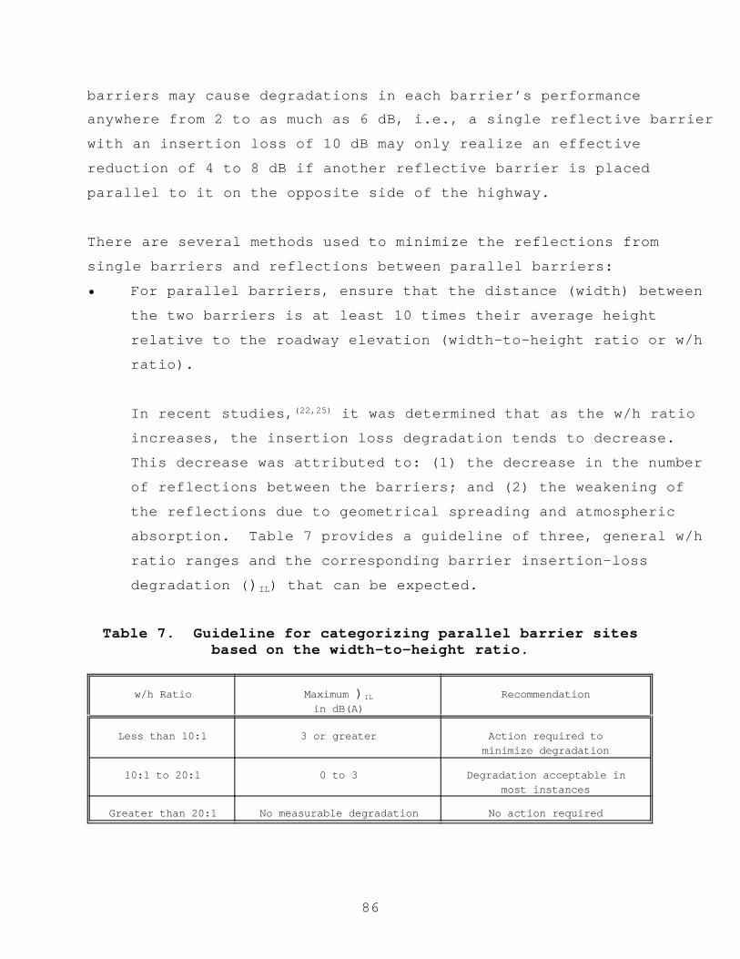
86
barriers may cause degradations in each barrier’s performanceanywhere from 2 to as much as 6 dB, i.e., a single reflective barrier
with an insertion loss of 10 dB may only realize an effective
reduction of 4 to 8 dB if another reflective barrier is placed
parallel to it on the opposite side of the highway.
There are several methods used to minimize the reflections from
single barriers and reflections between parallel barriers:
• For parallel barriers, ensure that the distance (width) between
the two barriers is at least 10 times their average height
relative to the roadway elevation (width-to-height ratio or w/h
ratio).
In recent studies,(22,25) it was determined that as the w/h ratio
increases, the insertion loss degradation tends to decrease.
This decrease was attributed to: (1) the decrease in the number
of reflections between the barriers; and (2) the weakening of
the reflections due to geometrical spreading and atmospheric
absorption. Table 7 provides a guideline of three, general w/h
ratio ranges and the corresponding barrier insertion-loss
degradation ()IL) that can be expected.
Table 7. Guideline for categorizing parallel barrier sitesbased on the width-to-height ratio.
w/h Ratio Maximum )IL
in dB(A)Recommendation
Less than 10:1 3 or greater Action required tominimize degradation
10:1 to 20:1 0 to 3 Degradation acceptable inmost instances
Greater than 20:1 No measurable degradation No action required
87
• Apply acoustically absorptive material on either one or bothbarrier facades. Absorptive treatment may be categorized by
the amount of incident sound that a barrier absorbs.
Currently, the Noise Reduction Coefficient (NRC) is the measure
of choice. NRC is defined as the arithmetic average of the
Sabine absorption coefficients, "Sab, at 250 Hz, 500 Hz, 1000
Hz, and 2000 Hz. Measurements to determine the "Sab of a facade
should be made in accordance with the American Society of
Testing and Materials (ASTM) Recommended Practice C 423-90a
(Reverberation Room Method).(40) An alternative method for
computing the NRC is to determine the absorption coefficients
using ASTM Recommended Practice C384-95a (Impedance Tube
Method).(41) The Reverberation Room method provides a measure of
material absorption for randomly incident sound while the
Impedance Tube method provides a measure of absorption for
normal incident sound. Typically, the reverberation room
method is used for determining NRC.
NRC values theoretically range from 0 to 1, where 0 indicates
that the barrier will reflect all the incident sound, and 1
indicates that the barrier will absorb all the incident sound.
However, very often when a material is tested in a
reverberation room (ASTM C423-90a), NRC values higher than 1
may be computed. This is the result of an anomaly in the test
procedure. To correct for this anomaly, and, in turn, obtain a
meaningful NRC, the four absorption coefficients should first
be normalized such that the highest one is equivalent to 1.0,
and the factor that was applied to the highest one should then,
in turn, be applied to the remaining three coefficients.
Typical NRC values for an absorptive barrier range from 0.6 to
0.9.

88
• Tilt one of the barriers outward away from the road. Previousresearch has shown that an angle as small as 7 degrees is quite
effective at minimizing degradations.(31) Note: This method
must consider structures higher than the opposite barrier.
High structures may be adversely affected by the reflected
sound.
6.8 NOISE BARRIER SOUND TRANSMISSION CLASS
A barrier may be described by the amount of noise it transmits, i.e.,
its Sound Transmission Class (STC). Measurements to determine the
STC of a section of a barrier should be made in accordance with ASTM
Recommended Practice E 413-87.(42)
Usually it is assumed that the sound transmitted through a barrier is
negligible relative to that which is diffracted over the top, i.e.,
the sound transmitted is at least 20 dB below that diffracted. Most
state transportation agencies specify a minimum STC for barriers
constructed within their state.

89
7. CONSTRUCTION EQUIPMENT NOISE MEASUREMENTS FOR HIGHWAY-RELATED
PROJECTS
This section describes recommended procedures for the measurement of
highway construction equipment noise. The results of these
measurements can be used to assess the potential noise impact of a
construction site associated with a highway-related project.
Highway construction site activity consists of several genericphases, including mobilization, clearing and grading, earthwork,
foundations, bridge construction, base preparation, paving, and
cleanup. Thus, any noise impact due to a construction site is
actually composed of contributions from each of these phases.(43)
The noise level associated with a particular construction phase is
determined by first measuring the levels of individual equipment,
then summing the individual contributions over a particular time
period. The types and numbers of construction equipment, and the
amount of time specific equipment operate in different modes are a
direct function of the construction phase.
For the procedures described herein, each type of construction
equipment will be characterized by up to four modes of operation as
appropriate: (1) the equipment is stationary in a passive operation
mode (STATIONARY-PASSIVE, e.g., a bulldozer at idle); (2) the
equipment is stationary in an active operation mode (STATIONARY-
ACTIVE, e.g., a bulldozer lifting earth, debris, etc.); (3) the
equipment is moving to another area within a site but is not actively
performing project-related activities (MOBILE-PASSIVE); and (4) the
equipment is mobile in an active operation mode (MOBILE-ACTIVE, e.g.,
a bulldozer moving while pushing earth, debris, etc).

90
7.1 SITE SELECTION
7.1.1 Site Characteristics
In determining overall noise levels associated with a particular
construction site, the first step is to establish reference noise
emission levels for each type of construction equipment operating in
each of the above four modes. As such, the general site
characteristics for determining reference noise emission levels for
construction equipment are somewhat similar to those presented inSection 5.1.1 for determining noise emissions for highway vehicles.
These characteristics are as follows:
• A flat open space free of large reflecting surfaces, such as
parked vehicles, signboards, buildings, or hillsides, located
within 30 m (100 ft) of either the construction equipment’s
path (if measurements of mobile operations are being
performed), its stationary position (if appropriate), or the
microphone(s).
• The ground surface within the measurement area is free of snow
and representative of acoustically hard, e.g., pavement, or
acoustically soft, e.g., grass, terrain.
• The line-of-sight from the microphone(s) to the construction
equipment being measured unobscured within an arc of 150
degrees.
• A predominant, ambient level at the measurement site low enough
to enable the measurement of uncontaminated vehicle pass-by
sound levels. Specifically, the difference between the lowest-
anticipated, vehicle pass-by, maximum A-weighted sound-pressure
level (LAFmx) and the A-weighted ambient level, as measured at
the 15-m (50-ft) microphone, should be at least 10 dB.
• The site to be located away from known noise sources, such as
airports, construction sites, rail yards, or heavily traveled
roadways, if possible.
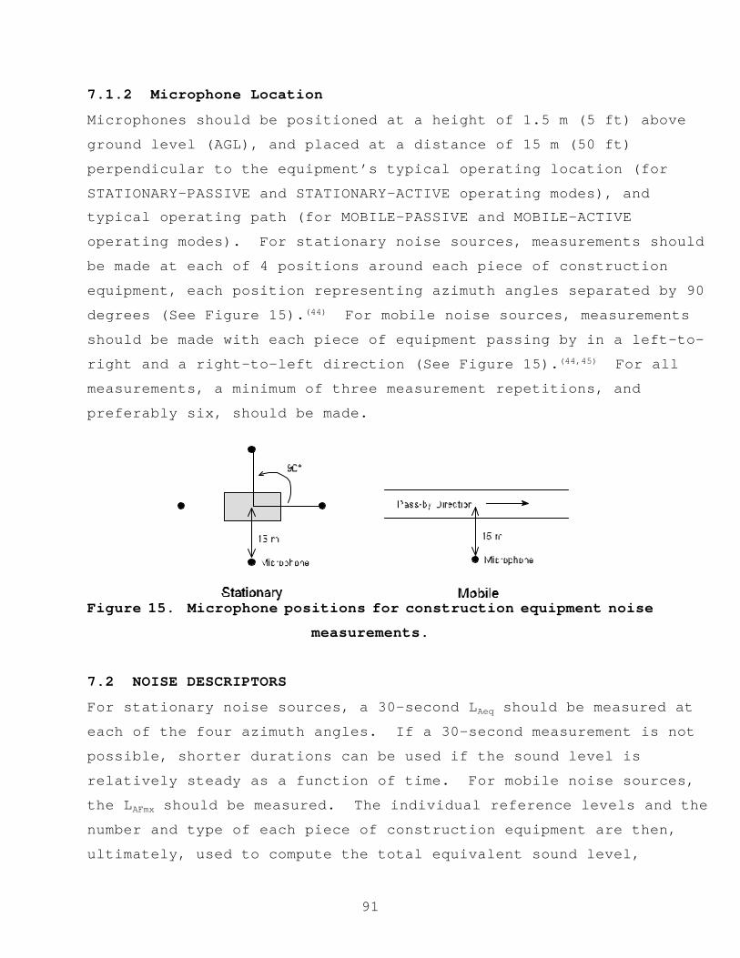
91
7.1.2 Microphone Location
Microphones should be positioned at a height of 1.5 m (5 ft) above
ground level (AGL), and placed at a distance of 15 m (50 ft)
perpendicular to the equipment’s typical operating location (for
STATIONARY-PASSIVE and STATIONARY-ACTIVE operating modes), andtypical operating path (for MOBILE-PASSIVE and MOBILE-ACTIVE
operating modes). For stationary noise sources, measurements should
be made at each of 4 positions around each piece of construction
equipment, each position representing azimuth angles separated by 90
degrees (See Figure 15).(44) For mobile noise sources, measurements
should be made with each piece of equipment passing by in a left-to-
right and a right-to-left direction (See Figure 15).(44,45) For all
measurements, a minimum of three measurement repetitions, and
preferably six, should be made.
Figure 15. Microphone positions for construction equipment noise
measurements.
7.2 NOISE DESCRIPTORS
For stationary noise sources, a 30-second LAeq should be measured at
each of the four azimuth angles. If a 30-second measurement is not
possible, shorter durations can be used if the sound level is
relatively steady as a function of time. For mobile noise sources,
the LAFmx should be measured. The individual reference levels and the
number and type of each piece of construction equipment are then,
ultimately, used to compute the total equivalent sound level,

92
LAeq,total, for a typical work day during a particular constructionphase. Note: Once the LAeq descriptor has been established for a
typical work day and construction phase, other descriptors can be
computed using the mathematical relationships presented in Section 2.
The LAeq descriptor may be more useful in assessing potential noise
impact due to construction-related activity.
7.3 INSTRUMENTATION (See Section 3)
Microphone system (microphone and preamplifier)
Graphic level recorder (optional)
Measurement/recording instrumentation
Calibrator
Microphone simulator
Pink noise generator
Windscreen
TripodCabling
Meteorological instrumentation
Tachometer (optional)
7.4 SAMPLING PERIOD
For each type of construction equipment, the sampling period willvary depending upon the operating mode (STATIONARY-PASSIVE,STATIONARY-ACTIVE, MOBILE-PASSIVE, and MOBILE-ACTIVE). For eachmode, the construction equipment should be operated in a manner whichis considered typical for the work period associated with aparticular mode. Due to the expected abundance of activity at aconstruction site, the sampling period may be based entirely on goodengineering judgment; and it will be up to the person performing themeasurements to ensure that representative high-quality data areobtained.

93
7.5 MEASUREMENT PROCEDURE1. The instrumentation should be deployed as shown in Figure 15.
2. Prior to initial data collection, at hourly intervalsthereafter, and at the end of the measurement day, the entireacoustic instrumentation system should be calibrated.Meteorological conditions (wind speed and direction,temperature, humidity, and cloud cover) should be documentedprior to data collection, at a minimum of 15-minute intervals,and whenever substantial changes in conditions are noted.
3. The electronic noise floor of the acoustic instrumentationsystem should be established daily by substituting themeasurement microphone with a dummy microphone (See Section3.1.5). The frequency response characteristics of the systemshould also be determined on a daily basis by measuring andstoring 30 seconds of pink noise from a random-noise generator(See Section 3.1.6).
4. Ambient levels should be measured and/or recorded by sampling
the sound level at each receiver with the sound source quieted
or removed from the site. A minimum of 10 seconds should be
sampled. Note: If the study sound source cannot be quieted or
removed, an upper limit to the ambient level using a
statistical descriptor, such as L90, may be used. Such upper
limit ambient levels should be reported as “assumed.” Note:
Most sound level meters have the built-in capability todetermine this descriptor.
5. For each mode, the construction equipment should be operated in
a manner which is considered typical for the work period and
the particular mode.

94
6. For each equipment type and operating mode, record the LAFmx orLAeq30s, as appropriate.
(Note: Appendix B provides example field-data log sheets.)
7.6 DATA ANALYSIS
1. Adjust measured levels for calibration drift (See Section
3.1.4).
2. Adjust measured levels for ambient (See Section 7.6.1).
3. Calculate an energy-averaged level (LAVG,j) of the LAeq30s values
obtained for each azimuth angle and each measurement repetition
of each equipment type in each stationary mode of operation, j
(See Section 7.4).
4. Calculate an energy-averaged level (LAVG,j) of the LAFmx values
obtained for each measurement repetition of each equipment type
in each mobile mode of operation, j (See Section 7.4).
5. Calculate the LAeq,i for each equipment type, i (See Section
7.6.2).
6. When all equipment measurements used for a particular phase are
complete, compute the LAeq,total for a typical workday during that
phase (See Section 7.6.3).
7. Perform an assessment of noise impact due to construction
equipment activity based on study objectives. In most
instances, the LAeq,total computed above will be used inEnvironmental Analyses to compare the potential impact of
different construction phases. If a particular noise-sensitive

95
receiver is a primary concern in the study, it is suggestedthat long-term existing-noise measurements be made at that
location, in accordance with the recommendations in Section 4.
7.6.1 Ambient Adjustments
If measured levels do not exceed ambient levels by 4 dB or more,
i.e., they are masked, then those data should be omitted from data
analysis.
If measured levels exceed the ambient levels by between 4 and 10
dB, then correct the measured levels for ambient as follows (Note:
For source levels which exceed ambient levels by greater than 10 dB,
ambient contribution becomes essentially negligible and no correction
is necessary):
(dB)
where: Ladj is the ambient-adjusted measured level;Lc is the measured level with source and ambient combined;andLa is the ambient level alone.
For example:• Lc = 55.0 dB• La = 47.0 dBTherefore:
Ladj = 10*log10(10(0.1*55.0)-10(0.1*47.0)) = 54.3 dB
7.6.2 Determination of the Equivalent Sound Level for Each Type of
Construction Equipment
The equivalent sound level for a particular type, i, of construction
equipment is computed as follows:
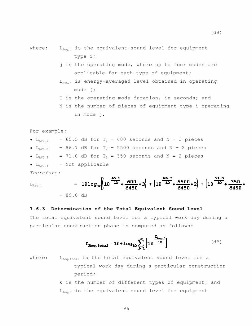
96
(dB)
where: LAeq,i is the equivalent sound level for equipment
type i;
j is the operating mode, where up to four modes are
applicable for each type of equipment;
LAVG,j is energy-averaged level obtained in operating
mode j;
T is the operating mode duration, in seconds; andN is the number of pieces of equipment type i operating
in mode j.
For example:
• LAVG,1 = 65.5 dB for T1 = 600 seconds and N = 3 pieces
• LAVG,2 = 86.7 dB for T2 = 5500 seconds and N = 2 pieces
• LAVG,3 = 71.0 dB for T3 = 350 seconds and N = 2 pieces
• LAVG,4 = Not applicable
Therefore:
LAeq,1 =
= 89.0 dB
7.6.3 Determination of the Total Equivalent Sound Level
The total equivalent sound level for a typical work day during a
particular construction phase is computed as follows:
(dB)
where: LAeq,total is the total equivalent sound level for a
typical work day during a particular constructionperiod;
k is the number of different types of equipment; and
LAeq,i is the equivalent sound level for equipment
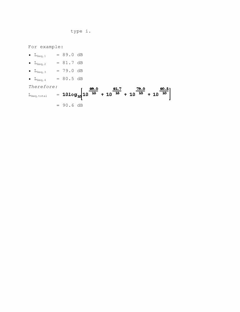
type i.
For example:
• LAeq,1 = 89.0 dB
• LAeq,2 = 81.7 dB
• LAeq,3 = 79.0 dB
• LAeq,4 = 80.5 dB
Therefore:
LAeq,total =
= 90.6 dB

98
8. BUILDING NOISE REDUCTION MEASUREMENTS IN THE VICINITY OF A
HIGHWAY
This section describes recommended procedures for the measurement of
building noise reduction, i.e., the effectiveness of a building
structure in insulating residents from outside noise sources, in this
case, highways. In contrast, these procedures may also be used to
determine how effectively a structure contains internal noise,
especially where the external environment is quieter than the noiseenvironment within the building.(20) The following procedures are in
accordance with the American Society of Testing and Materials (ASTM)
Standard E966-84.(32)
Two sets of measurements are recommended: (1) exterior measurements
of the roadway noise. (Note: If a traffic noise source is not
available, a fixed, artificial noise source, such as a loudspeaker,
may be used); and (2) interior measurements of the roadway noise
within the building itself. The difference between the exterior and
interior measured sound levels is the resulting noise reduction
performance for that building, or commonly referred to as the
“outdoor-indoor noise reduction.”
8.1 SITE SELECTION
8.1.1 Site Characteristics
8.1.1.2 Interior Measurements
The interior location should be a completely enclosed space with,
preferably, its largest dimension no greater than twice its smallest.
During measurements, all other noise-generating activities in the
room should be quieted. In addition, the interior ambient level
should be at least 10 dB below the lowest-anticipated, vehicle pass-
by, maximum A-weighted sound-pressure level (LAFmx).
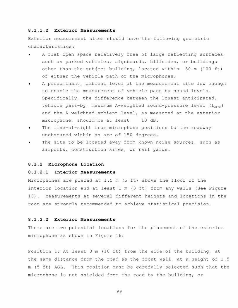
99
8.1.1.2 Exterior Measurements
Exterior measurement sites should have the following geometric
characteristics:
• A flat open space relatively free of large reflecting surfaces,such as parked vehicles, signboards, hillsides, or buildingsother than the subject building, located within 30 m (100 ft)of either the vehicle path or the microphones.
• A predominant, ambient level at the measurement site low enoughto enable the measurement of vehicle pass-by sound levels. Specifically, the difference between the lowest-anticipated,vehicle pass-by, maximum A-weighted sound-pressure level (LAFmx)and the A-weighted ambient level, as measured at the exteriormicrophone, should be at least 10 dB.
• The line-of-sight from microphone positions to the roadwayunobscured within an arc of 150 degrees.
• The site to be located away from known noise sources, such asairports, construction sites, or rail yards.
8.1.2 Microphone Location
8.1.2.1 Interior Measurements
Microphones are placed at 1.5 m (5 ft) above the floor of the
interior location and at least 1 m (3 ft) from any walls (See Figure
16). Measurements at several different heights and locations in the
room are strongly recommended to achieve statistical precision.
8.1.2.2 Exterior Measurements
There are two potential locations for the placement of the exterior
microphone as shown in Figure 16:
Position 1: At least 3 m (10 ft) from the side of the building, at
the same distance from the road as the front wall, at a height of 1.5
m (5 ft) AGL. This position must be carefully selected such that the
microphone is not shielded from the road by the building, or

100
influenced by noise sources behind the building. This positioningessentially eliminates influences on the measured levels due to
reflections. As such, this is the preferred position.
Position 2: Not greater than 2 m (6.6 ft) from the facade, located on
the roadway side of the building, at a point opposite the middle of
the facade, at a height of 1.5 m (5 ft) AGL. This setup is not
recommended if the roadway facade of the building is within 7.5 m (25
ft) of the centerline of the near lane of traffic.
Figure 16. Microphone positions for building noise reduction
measurements.
8.1.3 Artificial Noise Source Position
If a loudspeaker is used, it should be located at a distance from the
building facade such that the ratio of the distances from the
loudspeaker to the farthest (D1) and nearest (D2) edges of the facade
is no greater than two, i.e., D1/D2 # 2. The loudspeaker should beangled at an incidence within the range of 15 and 60 degrees,
preferably at an angle of 45 degrees (See Figure 17). This angle, 2
,is determined by the perpendicular to the facade midpoint and the
line joining the loudspeaker to the midpoint.

101
Figure 17. Loudspeaker position.
8.2 NOISE DESCRIPTORS
The equivalent sound level (LAeq) should be used to describecontinuous sounds, such as relatively dense highway traffic. The
sound exposure level (LAE), or the maximum A-weighted sound level
with fast time response characteristics (LAFmx), should be used to
describe the sound of single events, such as individual vehicle pass-
bys. The day-night average sound level (Ldn) and the community-noise
exposure level (Lden) may be used to describe long-term noise
environments (typically greater than 24 hours), particularly for
land-use planning. Note: Once the LAeq and LAE noise descriptors are
established, other descriptors can be computed using the mathematical
relationships presented in Section 2. Ultimately, the particular
descriptor chosen is of little importance since the objective of
these measurements is to obtain a change in sound level.
8.3 INSTRUMENTATION (See Section 3)
Microphone system (microphone and preamplifier)Graphic level recorder (optional)
Measurement/recording instrumentation
Calibrator
Microphone simulator
Pink noise generator
Windscreen
Tripod
Cabling

102
Meteorological instrumentationVehicle-speed detection unit
Traffic-counting device
Artificial noise source (if applicable)
8.4 SAMPLING PERIOD
Different sources may require different measurement periods. For
multiple-source conditions, a longer sampling period is needed to
obtain a representative sample averaged over all conditions. Typical
sampling periods are 15 minutes, 1 hr and 24 hr. Measurement
repetitions at all receiver positions are required to ensure
statistical reliability of measurement results. A minimum of 3
repetitions for like conditions is recommended, with 6 repetitions
being preferred. Table 5 in Section 4.4 presents suggested
measurement sampling periods based on the temporal nature and the
range in sound level fluctuations of the noise source. Guidance on
judgment of the temporal nature of the source may be found in ANSI
S1.13-1971.(16)
8.5 MEASUREMENT PROCEDURE
1. Prior to initial data collection, at hourly intervals
thereafter, and at the end of the measurement day, the entire
acoustic instrumentation system should be calibrated.
Meteorological conditions (wind speed and direction,
temperature, humidity, and cloud cover) should be documented
prior to data collection, at a minimum of 15-minute intervals,
and whenever substantial changes in conditions are noted.
2. The electronic noise floor of the acoustic instrumentationsystem should be established daily by substituting themeasurement microphone with a dummy microphone (See Section3.1.5). The frequency response characteristics of the systemshould also be determined on a daily basis by measuring and

* At distances greater than ¼-wavelength from the facade of the building, theincident and reflected waves result in a level 3 dB higher than would bemeasured due to the incident wave alone. Thus the 3-dB correction for the 2-mexterior microphone position is acceptable down to about 50 Hz.
103
storing 30 seconds of pink noise from a random-noise generator(See Section 3.1.6)
3. Ambient levels should be measured and/or recorded by samplingthe sound level at each receiver and at the referencemicrophone with the sound source quieted or removed from thesite. A minimum of 10 seconds should be sampled. Note: If thestudy sound source cannot be quieted or removed, an upper limitto the ambient level using a statistical descriptor, such asL90, may be used. Such upper limit ambient levels should bereported as “assumed.” Note: Most sound level meters have thebuilt-in capability to determine this descriptor.
4. The interior and exterior measurements should then be performedsimultaneously; and the characteristics of the source should becarefully documented (e.g., if actual highway traffic is beingused, the volume, speed, and mix should be recorded).
(Note: Appendix B provides example field-data log sheets.)
8.6 DATA ANALYSIS1. Adjust measured levels for calibration drift (See Section
3.1.4).
2. Adjust measured levels for ambient (See Section 8.6.1).
3. Compute the building noise reduction (NR) as follows:For exterior microphone at Position 1:
NR = Lexterior - Linterior (dB)
For exterior microphone at Position 2:*
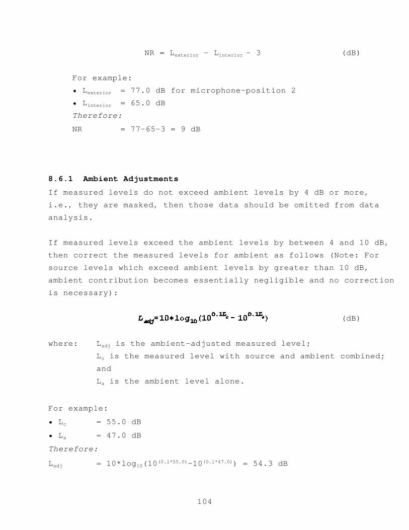
104
NR = Lexterior - Linterior - 3 (dB)
For example:• Lexterior = 77.0 dB for microphone-position 2• Linterior = 65.0 dBTherefore:
NR = 77-65-3 = 9 dB
8.6.1 Ambient Adjustments
If measured levels do not exceed ambient levels by 4 dB or more,i.e., they are masked, then those data should be omitted from dataanalysis.
If measured levels exceed the ambient levels by between 4 and 10 dB,then correct the measured levels for ambient as follows (Note: Forsource levels which exceed ambient levels by greater than 10 dB,ambient contribution becomes essentially negligible and no correctionis necessary):
(dB)
where: Ladj is the ambient-adjusted measured level;Lc is the measured level with source and ambient combined;andLa is the ambient level alone.
For example:
• Lc = 55.0 dB
• La = 47.0 dB
Therefore:
Ladj = 10*log10(10(0.1*55.0)-10(0.1*47.0)) = 54.3 dB
105
9. HIGHWAY-RELATED OCCUPATIONAL NOISE EXPOSURE MEASUREMENTS
This section describes recommended procedures for the measurement of
highway-related occupational noise exposure. Highway toll plaza and
tunnel employees, highway maintenance and repair crews, and highwayinspectors may be exposed to sound levels hazardous to hearing.
Occupational noise exposure was developed to rate a person's
susceptibility to hearing loss and to study noise environments that
may be hazardous to hearing.(8) The following procedures are in
accordance with ANSI S12.19-1996.(47)
For occupational noise exposures greater than 90 dB(A) in an 8-hour
workday, the Occupational Safety and Health Administration (OSHA)
requires mandatory hearing-conservation measures, such as audiometric
testing or hearing protectors. OSHA defines a 90-dB(A) noise
exposure as the criterion sound level, denoted herein by the symbol,
LC; OSHA defines an 8-hour workday as the criterion duration, denoted
herein by the symbol, TC.(48) A continuous criterion sound level over
an entire criterion duration would result in 100 percent of an
employee's allowable noise exposure. In addition, for exposures
greater than 90 dB(A), some type of noise abatement action, such as
machinery noise reduction via redesign or replacement,
source/receiver isolation/enclosure, or employee exposure time
limits, must be initiated.
For varying exposure durations, OSHA limits may be adjusted
accordingly by the use of an exchange rate. For occupational noise
exposure studies, OSHA requires the use of a 5-dB(A) exchange rate.
In other words, for each additional 5 dB(A) of noise exposure up to
115 dB(A), the permitted duration is halved; for each reduction of 5dB(A), the permitted duration is doubled. For example, if the noise

106
exposure is 95 dB(A), a duration of 4 hours is permissible accordingto OSHA.
In addition, OSHA states that “exposure to impulsive or impact noise
level should not exceed 140 dB.” However, the regulations do not
define what constitutes an impulsive or impact sound, nor do they
address frequency weighting (See Section 3.1.3.4.2) of the measuring
instrument, or whether the measurement uses one or none of the
standard exponential time-averagings (See Section 3.1.3.4.4).(8) For
the purposes of this document, it is recommended that the maximum A-
weighted sound level, LAFmx, be used to ensure the 140 dB criterion is
met.
9.1 SITE SELECTION
For the purposes of noise exposure measurements, a noise dosimeter or
a sound level meter can be used. To a certain degree, the particular
instrument chosen will dictate the site-selection process.
9.1.1 Noise Dosimeter
The noise dosimeter should be worn by the employee during his/ her
daily work routine. Its accompanying microphone should, preferably,
be located on the employee's shoulder. If the employee is
consistently exposed to noise from one particular side, the
microphone should be placed on the associated side. The microphone
cable, which connects to the dosimeter, should be routed and fastened
such that it does not interfere with the employee's safety or
performance. The main body of the dosimeter may be located/attached
to the employee's clothing at any convenient location. If the
employee works at only one particular station, or if the employee
will not be present during measurements, the dosimeter may be placed
on a tripod at a representative position within the area.

107
9.1.2 Sound Level Meter
Because of their larger size as compared with noise dosimeters, and
due to the fact that they often do not have readily detachable
microphones, sound level meters are often not logistically feasible
to be worn directly by an employee. Consequently, they are typicallypositioned on a tripod within the work area. Specifically, the
microphone should be positioned at a height approximately equal to
that of the employee's head and as close as possible to the his/her
ear. ANSI 12.19-1996 recommends a distance of 0.1 m (4 in) from the
employee's ear, if feasible. In addition, the microphone should be
placed such that shielding by the employee or other objects is
avoided. If the employee works at only one particular station, or if
the employee will not be present during measurements, the microphone
and sound level meter may be placed on a tripod at a representative
position within the area.
9.2 NOISE DESCRIPTORS
The equivalent sound level, LAeq, and the duration of each measurement
period should be recorded. The LAeq and the duration are then used to
compute noise dose, which is, in turn, used to compute the time-
weighted average sound level (LTWA(TC)), i.e., the employee's "noise
exposure." As stated earlier, TC is the OSHA criterion duration of 8
hours. In addition, the maximum A-weighted sound level, LAFmx, should
be recorded to ensure that the employee is not subjected to impulsive
or impact noise levels greater than 140 dB(A).
9.3 INSTRUMENTATION (See Section 3)
Microphone system (microphone and preamplifier)
Graphic level recorder (optional)
Noise dosimeter or sound level meter
Calibrator
Microphone simulator
108
Windscreen (if the employee’s primary work area is outdoors)Tripod
Cabling
Meteorological instrumentation (if the employee’s primary
work area is outdoors)
9.4 SAMPLING PERIOD
The measurement duration should be sufficiently long, such that the
resulting noise exposure is representative of the noise exposure
associated with each task/location. For continually varying sound
environments (sound level fluctuations greater ± 2.5 dB(A)), a
longer sampling period is recommended. In most cases, noise exposure
measurements are performed over a typical 8-hour work day.
9.5 MEASUREMENT PROCEDURES
1. Prior to initial data collection, after data collection is
complete, and at convenient times throughout the measurement
day, calibrate the noise dosimeter or sound level meter.
2. Record the LAeq and the associated duration in addition to the
LAFmx for each measurement period. Note: For a measurement to
be considered valid:
a. The microphone should not be moved from its original
position during the measurement period.
b. The employee should not speak directly into the
microphone.
c. The unit should be periodically checked for proper use.
(Note: Appendix B provides example field-data log sheets.)
9.6 DATA ANALYSIS

109
1. Adjust measured levels for calibration drift (See Section3.1.4).
2. Calculate the noise dose for a typical workday (See Section9.6.1).
3. Calculate the noise exposure for a typical workday (See Section9.6.2).
4. Perform an assessment of noise impact based on the calculated
noise exposure. The maximum recorded sound levels for each
task/location should also be considered in the assessment. The
overall objective of any assessment should be to determine the
necessity to implement hearing-conservation measures, or some
type of noise abatement action.
9.6.1 Determination of Noise Dose
The total noise dose for a typical workday is a summation of the
individual task/location noise doses and is computed as follows:
(%)
where:
The variables in the above equations are defined as follows:
D = Noise dose, expressed as a percentage;
Ci = Measurement duration at task/location i;
Ti = Permissible duration at task/location i;
LAeq,i = Equivalent sound level measured during task/ location,
i (Note: If the LAeq,i for a specific measurement period
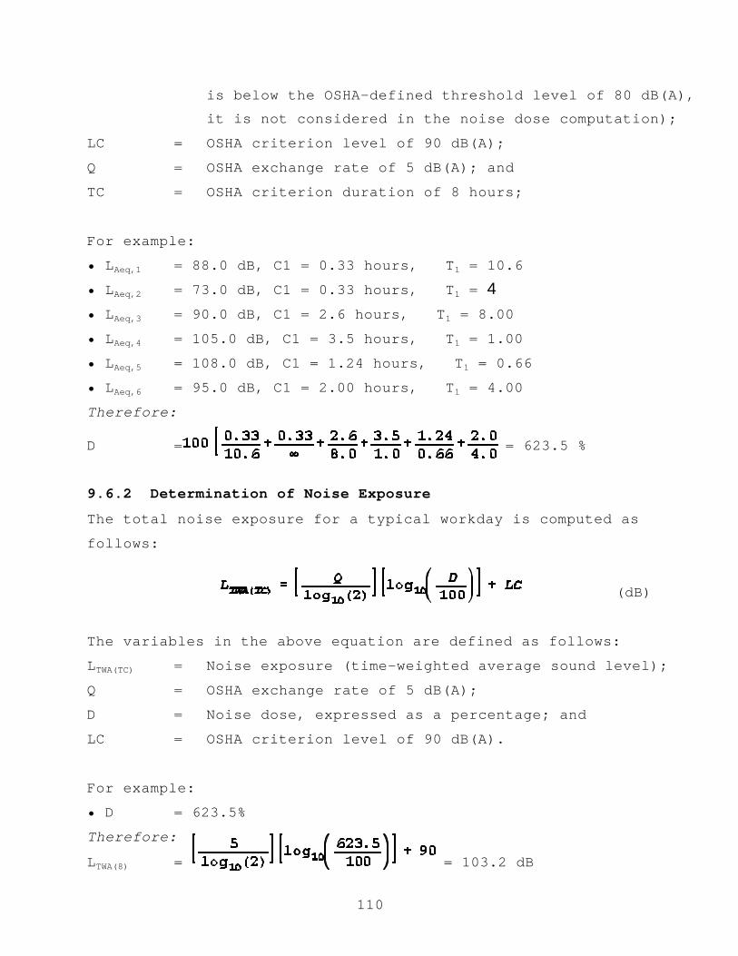
110
is below the OSHA-defined threshold level of 80 dB(A),it is not considered in the noise dose computation);
LC = OSHA criterion level of 90 dB(A);
Q = OSHA exchange rate of 5 dB(A); and
TC = OSHA criterion duration of 8 hours;
For example:
• LAeq,1 = 88.0 dB, C1 = 0.33 hours, à T1 = 10.6
• LAeq,2 = 73.0 dB, C1 = 0.33 hours, à T1 = 4• LAeq,3 = 90.0 dB, C1 = 2.6 hours, à T1 = 8.00
• LAeq,4 = 105.0 dB, C1 = 3.5 hours, à T1 = 1.00
• LAeq,5 = 108.0 dB, C1 = 1.24 hours, à T1 = 0.66
• LAeq,6 = 95.0 dB, C1 = 2.00 hours, à T1 = 4.00
Therefore:
D = = 623.5 %
9.6.2 Determination of Noise Exposure
The total noise exposure for a typical workday is computed as
follows:
(dB)
The variables in the above equation are defined as follows:
LTWA(TC) = Noise exposure (time-weighted average sound level);
Q = OSHA exchange rate of 5 dB(A);
D = Noise dose, expressed as a percentage; and
LC = OSHA criterion level of 90 dB(A).
For example:
• D = 623.5%
Therefore:
LTWA(8) = = 103.2 dB

111


113
10. REPORT DOCUMENTATION
This section details the information to be documented in the fieldmeasurement report. It is general enough to be applicable to allsections discussed herein. Report documentation shall include allprocedures in sufficient detail such that the measurement results canbe repeated. It shall include clearly stated measurement objectives,field measurement equipment and detailed field measurementprocedures, a description of the noise source, the descriptors used,and detailed data analyses and results, including detailedmeteorological conditions.(6,8,49) A sample computation ofexperimental error is also recommended. Note: A sample report hasbeen provided in Appendix D.
10.1 SITE SKETCHES
10.1.1 Plan ViewA plan view illustrates the site as if looking down upon it fromabove. The plan view should include the location of the source(s),receiver(s), and any notable geographical objects, such as trees,bodies of water, hills, buildings, and signs. Relative distances ofall objects should also be indicated (See Figure 18).
Figure 18. Sample plan view.10.1.2 Elevation View
An elevation view illustrates the site from a viewpoint normal to the
ground plane, cutting across or slicing the cross-section. It should

114
include the relative slopes and elevations of the source, receiver,terrain, buildings, and other objects at that site for a given
source-receiver pair (See Figure 19).
Figure 19. Sample elevation view.
10.2 SOURCE DESCRIPTION
A detailed description of the source should be provided. If
applicable, this may include information regarding make, model, type,
speed, etc., if an individual noise source; or volume and speed, if a
fleet of vehicles.
10.3 INSTRUMENTATION DESCRIPTION
The manufacturer, model number, serial number, and parameter
settings, including gain settings, for all instrumentation should be
documented. A block diagram of the measurement and analysis systems
should also be included. Calibration, frequency response, and noise
floor data should all be provided.
10.4 METEOROLOGICAL DATA
Weather conditions should be documented at a minimum of 15-minute
intervals, and whenever substantial changes in conditions are noted.
These conditions include wind speed, wind direction, temperature,
humidity, cloud cover, and time-of-day when these data were measured.
10.5 GROUND SURFACE CHARACTERIZATION

115
The ground characteristics for both the sources and receivers shouldalso be documented, e.g., hard or soft ground (See Section 2).
10.6 BARRIER CHARACTERISTICS
For barrier insertion loss measurements, the following barrier
characteristics need to be documented: barrier height, length,
location, material, Noise Reduction Coefficient, Sound Transmission
Class, and tilt angle (if applicable).
10.7 MEASUREMENT PROCEDURES
All field measurement procedures should be documented. These
procedures should be detailed such that the measurement results are
able to be repeated by other individuals.
10.8 ACOUSTICAL DATA
Data acquired from field measurements and analyses, as well as the
procedures used, should be documented fully. Also to be recorded are
all adjustments applied to the data due to calibration drift, ambient
influences, and instrumentation non-linearities.
10.9 INCIDENTAL OBSERVATIONS AND CONCLUSIONS
A discussion of any unforeseen events during the measurements should
be included. Any situations that suggest modifications to the
experiment for improved results should be documented. Any relevant
subjective judgments or interpretations may appear in this section of
the measurement report.

116
APPENDIX A
RELATIVE HUMIDITY COMPUTATION
This appendix presents the procedures for converting measured dry and
wet bulb temperatures into relative humidity expressed in percent.
1. Convert Dry Bulb temperature from °F to °C:
Dry, °C =
2. Convert Dry Bulb temperature from °C to °K:
Dry, °K = (Dry,°C) + 273.15
3. Repeat steps 1 and 2 to convert Wet Bulb temperature (Wet) to
°K.
4. Compute the Saturation Pressure, assuming standard-day ambient
atmosphere pressure, for the Dry Bulb temperature (DrySatPres):
DrySatPres =
5. Repeat step 4 to compute the Saturation Pressure for the Wet
Bulb temperature (WetSatPres).
6. Compute the Relative Humidity (RH) in percent:
RH, % =


129
APPENDIX B
SAMPLE DATA LOG SHEETS
This appendix contains sample field-data log sheets for use with the
measurement procedures described within the main body of the
document.

130
Page of
Table 8. Sample instrumentation log.
Site #: 1 Date: 5/1/96 Location: I-95 S
Item #: Quantity: Instrument Type: Serial #:
1 1 Brüel & Kjær 4155 Microphone 43515
2 1 Brüel & Kjær 4155 Microphone 43516
3 1 Larson Davis 820 Sound Level Meter 33768
4 1 Larson Davis 820 Sound Level Meter 33769
5 1 Cetec Ivie Random Noise Generator 501
6 2 Microphone Simulators N/A
7 3 Brüel & Kjær 0237 Windscreens N/A
8 1 Wind-Cup Anemometer N/A
9 1 Sling Psychrometer N/A
10 1 100-Ft Tape Measure N/A
11 10 9-Volt Batteries N/A
12 1 Flashlight N/A
13 10 D-Cell Batteries N/A
131
Page of
Table 9. Blank instrumentation log.
Site #: Date: Location:
Item #: Quantity: Instrument Type: Serial #:

132
Page of
Table 10. Sample site data log.
Site #: 1 Date: 5/1/96 Location: I-95 S Observer: Joe
Lane Dir:South
Site Surface:Soft
Nearby Landmark: I-495 Junction
Grade: 0% Pavement Type:Concrete
Distance to Landmark:0.25 km
Plan View:
Elevation View:

133
Page of
Table 11. Blank site data log.
Site #: Date: Location: Observer:
Lane Dir: Site Surface: Nearby Landmark:
Grade: Pavement Type: Distance to Landmark:
Plan View:
Elevation View:
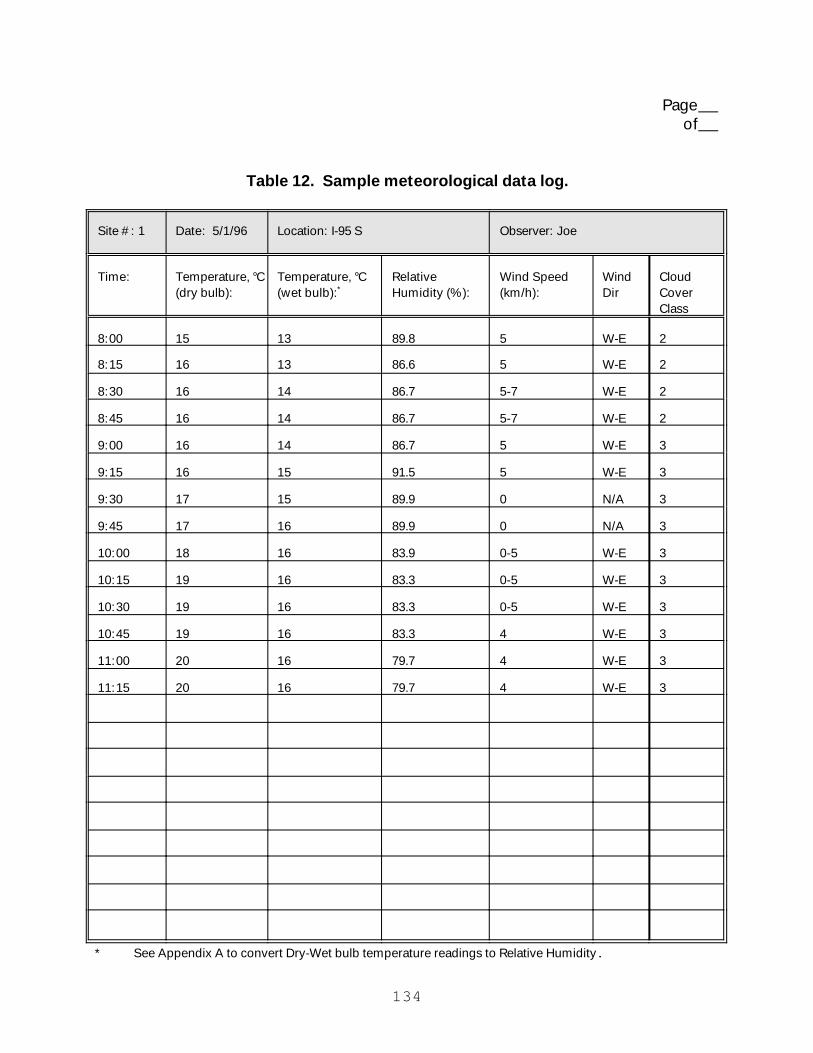
134
Page of
Table 12. Sample meteorological data log.
Site #: 1 Date: 5/1/96 Location: I-95 S Observer: Joe
Time: Temperature, °C(dry bulb):
Temperature, °C(wet bulb):*
RelativeHumidity (%):
Wind Speed(km/h):
WindDir
CloudCoverClass
8:00 15 13 89.8 5 W-E 2
8:15 16 13 86.6 5 W-E 2
8:30 16 14 86.7 5-7 W-E 2
8:45 16 14 86.7 5-7 W-E 2
9:00 16 14 86.7 5 W-E 3
9:15 16 15 91.5 5 W-E 3
9:30 17 15 89.9 0 N/A 3
9:45 17 16 89.9 0 N/A 3
10:00 18 16 83.9 0-5 W-E 3
10:15 19 16 83.3 0-5 W-E 3
10:30 19 16 83.3 0-5 W-E 3
10:45 19 16 83.3 4 W-E 3
11:00 20 16 79.7 4 W-E 3
11:15 20 16 79.7 4 W-E 3
* See Appendix A to convert Dry-Wet bulb temperature readings to Relative Humidity.

135
Page of
Table 13. Blank meteorological data log.
Site #: Date: Location: Observer:
Time: Temperature, °C(dry bulb):
Temperature, °C(wet bulb):*
RelativeHumidity (%):
Wind Speed(km/h):
WindDir
CloudCoverClass
* See Appendix A to convert Dry-Wet bulb temperature readings to Relative Humidity.

Page of
Table 14. Existing-noise measurementsSample acoustic data log.
Site #: 1 Date: 5/1/96 Location: I-95 S Observer: Joe
Site Type(Check one):
Overall Sound Level Change in Sound Level Mic Type(Check one):
Reference Receiver Mic #: 1
Mic Location: 7.5 m. offset
BEFORE AFTER T
T
Event #: Time: Duration(sec):
SoundLevel (dB):
Gain Setting: Comments:
PreCal 8:00:31 25.0 N/A 0
Cal 8:05:24 20.125 N/A Reset SLM
Dummy 8:09:01 30.125 N/A
Pink 8:15:00 31.625 N/A
PreCal 8:45:23 22.0 N/A
Cal 8:55:15 20.25 N/A
1 9:05:00 300.0 56.4 +20
2 9:10:00 300.0 65.7


Page of
Table 15. Existing-noise measurementsBlank acoustic data log.
Site #: Date: Location: Observer:
Site Type(Check one):
Overall Sound Level Change in Sound Level Mic Type(Check one):
Reference Receiver Mic #: Mic Location:
BEFORE AFTER
Event #: Time: Duration(sec):
SoundLevel (dB):
Gain Setting: Comments:


Page of
Table 16. Existing-noise measurementsSample vehicle data log.
Site #: 1 Date: 5/1/96 Location (Traffic Direction/Lane, etc.): I-95 (Southbound on Lane1)
Observer: Joe
Event #: Time: PredominantVehicle Speed(km/h):
Auto: MediumTruck:
HeavyTruck:
Bus: Motor-cycle:
Other: Comments:
1 9:05:00 80
2 9:10:00 85


Page of
Table 17. Existing-noise measurementsBlank vehicle data log.
Site #: Date: Location (Traffic Direction/Lane, etc.): Observer:
Event #: Time: PredominantVehicle Speed(km/h):
Auto: MediumTruck:
HeavyTruck:
Bus: Motor-cycle:
Other: Comments:

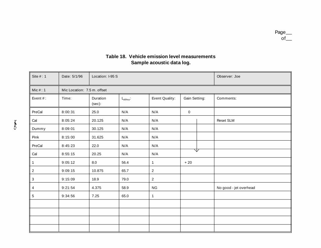
Page of
Table 18. Vehicle emission level measurementsSample acoustic data log.
Site #: 1 Date: 5/1/96 Location: I-95 S Observer: Joe
Mic #: 1 Mic Location: 7.5 m. offset
Event #: Time: Duration(sec):
LAFmx: Event Quality: Gain Setting: Comments:
PreCal 8:00:31 25.0 N/A N/A 0
Cal 8:05:24 20.125 N/A N/A Reset SLM
Dummy 8:09:01 30.125 N/A N/A
Pink 8:15:00 31.625 N/A N/A
PreCal 8:45:23 22.0 N/A N/A
Cal 8:55:15 20.25 N/A N/A
1 9:05:12 8.0 56.4 1 +20
2 9:09:15 10.875 65.7 2
3 9:15:09 18.9 79.0 2
4 9:21:54 4.375 58.9 NG No good - jet overhead
5 9:34:56 7.25 65.0 1


Page of
Table 19. Vehicle emission level measurementsBlank acoustic data log.
Site #: Date: Location: Observer:
Mic #: Mic Location:
Event #: Time: Duration(sec):
LAFmx: Event Quality: Gain Setting: Comments:


Page of
Table 20. Vehicle emission level measurementsSample vehicle data log.
Site #: 1 Date: 5/1/96 Location (Traffic Direction/Lane, etc.): I-95 (Southbound on Lane1)
Observer: Joe
Event #: Time: Vehicle Speed(km/h):
Auto: MediumTruck:
HeavyTruck:
Bus: Motor-cycle:
Other: Comments:
1 9:05:12 80 T 5 axle
2 9:09:15 85 T
3 9:15:09 75 T 3 axle
4 9:21:54 88 T
5 9:34:56 90 T

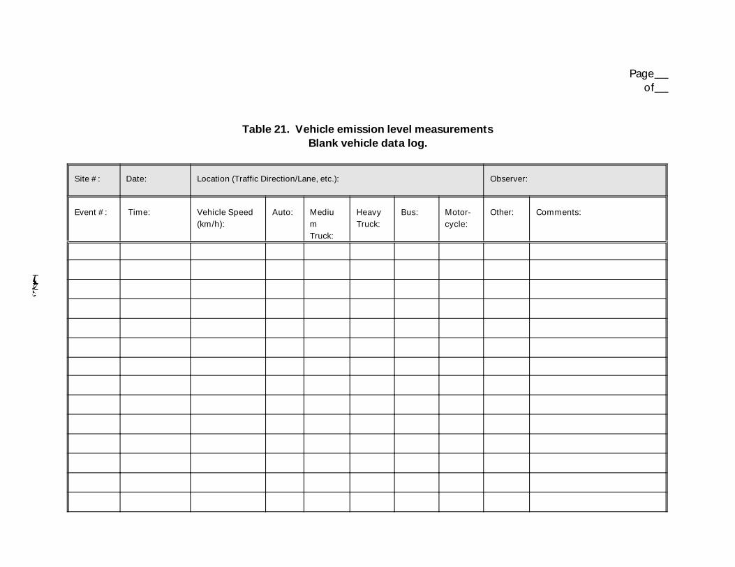
Page of
Table 21. Vehicle emission level measurementsBlank vehicle data log.
Site #: Date: Location (Traffic Direction/Lane, etc.): Observer:
Event #: Time: Vehicle Speed(km/h):
Auto: MediumTruck:
HeavyTruck:
Bus: Motor-cycle:
Other: Comments:


Page of
Table 22. Barrier insertion loss measurementsSample acoustic data log.
Site #: 1 Date: 5/1/96 Location: I-95 S Observer: Joe
Site Type(Check one):
BEFORE Equiv. BEFORE AFTER Mic Type(Check one):
Reference Receiver Mic #: 1
Mic Location: 7.5 m. offset
T T
Event #: Time: Duration(sec):
Sound Level(dB):
Event Quality(if applicable):
GainSetting:
Comments:
PreCal 8:00:31 25.0 N/A N/A 0
Cal 8:05:24 20.125 N/A N/A Reset SLM
Dummy 8:09:01 30.125 N/A N/A
Pink 8:15:00 31.625 N/A N/A
PreCal 8:45:23 22.0 N/A N/A
Cal 8:55:15 20.25 N/A N/A
1 9:15:00 300.0 56.4 N/A +20
2 9:20:00 300.0 65.7 N/A

Page of
Table 23. Barrier insertion loss measurementsBlank acoustic data log.
Site #: Date: Location: Observer:
Site Type(Check one):
BEFORE Equiv. BEFORE AFTER Mic Type(Check one):
Reference Receiver Mic #: Mic Location:
Event #: Time: Duration(sec):
Sound Level(dB):
Event Quality(if applicable):
GainSetting:
Comments:

Page of
Table 24. Barrier insertion loss measurementsSample vehicle data log.
Site #: 1 Date: 5/1/96 Location (Traffic Direction/Lane, etc.): I-95 (Southbound on Lane1)
Observer: Joe
Event #: Time: PredominantVehicle Speed(km/h):
Auto: MediumTruck:
HeavyTruck:
Bus: Motor-cycle:
Other: Comments:
1 9:15:00 80
2 9:20:00 85


Page of
Table 25. Barrier insertion loss measurementsBlank vehicle data log.
Site #: Date: Location (Traffic Direction/Lane, etc.): Observer:
Event #: Time: PredominantVehicle Speed(km/h):
Auto: MediumTruck:
HeavyTruck:
Bus: Motor-cycle:
Other: Comments:


Page of
Table 26. Construction equipment noise measurementsSample acoustic data log.
Site #: 1 Date: 5/1/96 Location/Construction Phase: I-95 S /Earthwork Observer: Joe
Operating Mode(Check one):
Stationary-Passive
Stationary-Active
Mobile-Passive
Mobile-Active
Equipment Type:Bulldozer
Mic #: 1 Mic Location:15 m. offset
T
Event #: Time: Duration(sec):
Sound Level(dB):
EquipmentSpeed (km/h):
Gain Setting: Comments:
PreCal 8:00:31 25.0 N/A N/A 0
Cal 8:05:24 20.125 N/A N/A Reset SLM
Dummy 8:09:01 30.125 N/A N/A
Pink 8:15:00 31.625 N/A N/A
PreCal 9:15:23 22.0 N/A N/A
Cal 9:20:15 20.25 N/A N/A
1 10:00:07 8.0 56.4 5 +20
2 10:05:15 10.875 65.7 6
3 10:09:56 18.9 79.0 5
4 10:14:37 4.375 58.9 7 No good - dogs barking
5 10:21:21 7.25 65.0 5


Page of
Table 27. Construction equipment noise measurementsBlank acoustic data log.
Site #: Date: Location/Construction Phase: Observer:
Operating Mode(Check one):
Stationary-Passive
Stationary-Active
Mobile-Passive
Mobile-Active
Equipment Type: Mic #: Mic Location:
Event #: Time: Duration(sec):
Sound Level(dB):
EquipmentSpeed (km/h):
Gain Setting: Comments:


Page of
Table 28. Building noise reduction measurementsSample acoustic data log.
Site #: 1 Date: 5/1/96 Location: 55 Broadway Street off I-95 S Observer: Joe
Site Type(Check one):
Interior Exterior
T
Event #: Time: Duration(sec):
Sound Level(dB):
Event Quality(if applicable):
GainSetting:
Comments:
PreCal 8:00:31 25.0 N/A N/A 0
Cal 8:05:24 20.125 N/A N/A Reset SLM
Dummy 8:09:01 30.125 N/A N/A
Pink 8:15:00 31.625 N/A N/A
PreCal 8:45:23 22.0 N/A N/A
Cal 8:55:15 20.25 N/A N/A
1 9:30:01 8.0 56.4 1 +20
2 9:36:15 10.875 65.7 2


Page of
Table 29. Building noise reduction measurementsBlank acoustic data log.
Site #: Date: Location: Observer:
Site Type(Check one):
Interior Exterior
Event #: Time: Duration(sec):
Sound Level(dB):
Event Quality(if applicable):
GainSetting:
Comments:


Page of
Table 30. Building noise reduction measurementsSample vehicle data log.
Site #: 1 Date: 5/1/96 Location (Traffic Direction/Lane, etc.): I-95 (Southbound on Lane1)
Observer: Joe
Event #: Time: PredominantVehicle Speed(km/h):
Auto: MediumTruck:
HeavyTruck:
Bus: Motor-cycle:
Other: Comments:
1 9:30:01 80
2 9:36:15 85

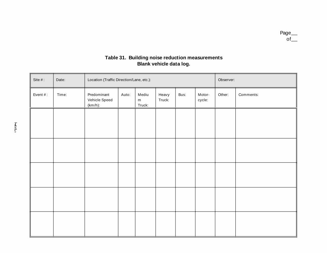
Page of
Table 31. Building noise reduction measurementsBlank vehicle data log.
Site #: Date: Location (Traffic Direction/Lane, etc.): Observer:
Event #: Time: PredominantVehicle Speed(km/h):
Auto: MediumTruck:
HeavyTruck:
Bus: Motor-cycle:
Other: Comments:


Page of
Table 32. Sample occupational noise exposure data log.
Site #: 1 Date: 5/1/96 Task/Location: I-95 S Toll booth at Exit 19 Employee/Observer: Joe/Fred
Instrumentation(Check one):
NoiseDosimeter
Sound LevelMeter
Mic Location: Shoulder
T
Event #: Time: Duration(hour):
LAeq
(dB):LAFmx
(dB):GainSetting:
Comments:
PreCal 7:00:31 25.0 sec N/A 0
Cal 7:05:24 20.125 sec N/A Reset SLM
Dummy 7:09:01 30.125 sec N/A
Pink 7:15:00 31.625 sec N/A
PreCal 7:45:23 22.0 sec N/A
Cal 7:55:15 20.25 sec N/A
1 8:07:12 0.33 88.0 90.1 +20
2 8:30:15 0.33 73.0 77.9
3 8:52:09 2.60 90.0 90.9
4 11:15:12 3.50 105.0 105.1
5 15:08:15 1.24 108.0 109.0
6 16:25:09 2.00 95.0 96.9

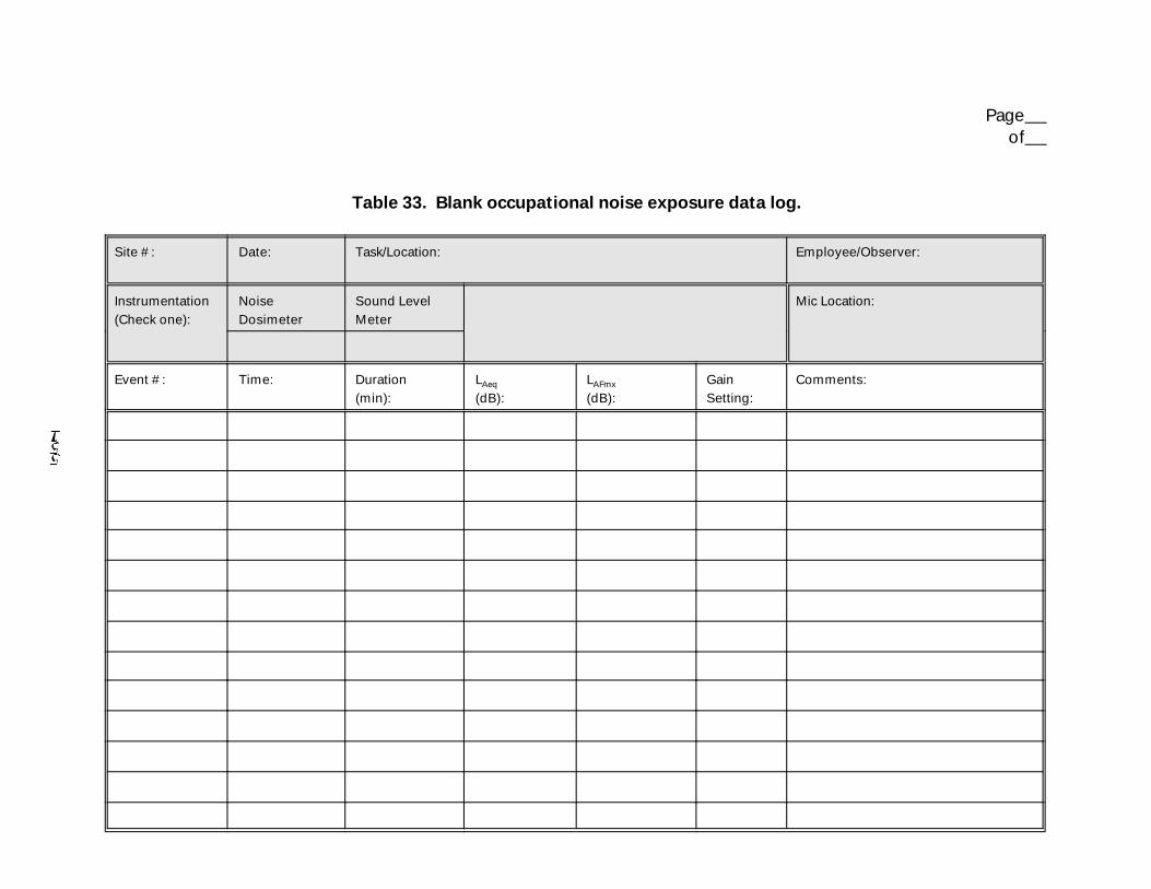
Page of
Table 33. Blank occupational noise exposure data log.
Site #: Date: Task/Location: Employee/Observer:
Instrumentation(Check one):
NoiseDosimeter
Sound LevelMeter
Mic Location:
Event #: Time: Duration(min):
LAeq
(dB):LAFmx
(dB):GainSetting:
Comments:


175
APPENDIX CMINIMUM SEPARATION-DISTANCE CRITERIA FOR NOISE EMISSION LEVEL
MEASUREMENTS
The minimum separation-distance criteria were based on Caltrans’California REMEL study.(24)
In the Caltrans study, the following assumptions were made: (1) thevehicle behaves as a point source, i.e., spherical divergence is
assumed; and (2) there is no ground attenuation of the emissionlevel. In addition, the ambient level was at least 10 dB less thanthe LAFmx of the observed vehicle.
In general, when a vehicle approaches a measurement microphone at aconstant speed, the observed sound level at the microphone is relatedto the vehicle position as follows:
where: L2 is the contribution to the measured emission levelof the subject vehicle, Vehicle 1 at X1, due to asubsequent vehicle, Vehicle 2, at X2;
L1 is the contribution to the measured emission levelof the subject vehicle, Vehicle 1, due entirelyto Vehicle 1 at X1;
)X is the distance between X1 and X2, or the minimumseparation distance to be determined; and
D is the distance from the microphone to X1, or 15 min this case.
If other vehicles are in proximity of the subject vehicle to be
measured, the measured sound level at the microphone for the subject

176
vehicle may increase due to contamination. A maximum of 0.5 dBcontamination is considered allowable.
Based on the 0.5-dB criterion, the next step is to determine the
associated separation-distance criteria. Potential sources of
contamination include contamination due to ambient noise, as well as
contamination due to other vehicles in proximity of the subject
vehicle (See Figure 20 on the following page).
The maximum contamination due to ambient noise was determined to be
0.4 dB, assuming the ambient level is 10 dB less than the LAFmx of
observed vehicles. Consequently, a maximum 0.1-dB contamination due
to subsequent vehicles, based on the 0.5-dB contamination criterion,
is allowed.
To ensure no more than 0.1-dB contamination due to subsequent
vehicles, it was determined that the emission level due to a
subsequent vehicle, Vehicle 2 in the case of Figure 20, must be at
least 15.9 dB below that of the subject vehicle, Vehicle 1. The next
step was to determine the separation distance associated with the
15.9-dB requirement.
Using the above equation and substituting the following values:
L2 = LAFmx - 15.9
D = 15 m,
)X was solved for.

177
Figure 20. Minimum separation distance
between two similar vehicles.
For REMELs measured at 15 m (50 ft), a minimum separation distance of
93.9 m (308 ft) between similar vehicles was required to ensure that
the total contamination was not greater than 0.5 dB. For automobiles
in the vicinity of heavy trucks, a minimum separation distance of
300.2 m (985 ft) between the automobile and heavy truck was required,
assuming a heavy truck is 10 dB louder than an automobile at
comparable speeds.


179
APPENDIX D
SAMPLE REPORT DOCUMENTATION
The objective of this appendix is to exemplify the types of
information to be documented in a field measurement report. For
the purposes of this appendix, assume existing-noise measurements
were performed (See Section 4).
D.1 Site Sketches
The measurement site was located on Route 95 (a 2-lane highway)
0.8 km past Exit 21. A reference microphone was attached to a
mast, placed at a height of 1.5 m above the roadway pavement, and
located at a 15 m offset position from the centerline of the neartravel lane. Another portable mast was fitted with three
microphones, placed at heights of 1.5 m (low), 4.5 m (middle), and
7.5 m (high), and located at a 30-m offset position. When
referring to microphone heights, the high, middle, and low
convention will be used for the remainder of this report. Figures
D1 and D2 present the plan and elevation views, respectively.

180
Figure D1. Measurement site plan view.
Figure D2. Measurement site elevation view.
D.2 Source Description
The source was constant free-flowing traffic traveling on Route 95.
Traffic volume and mix were recorded on video cassette and used to
obtain vehicle counts. Vehicles were counted and classified in three
categories: automobiles (A); medium trucks (MT); and heavy trucks
(HT). Vehicles were further grouped by direction (eastbound and
westbound). Vehicle counts and average speed for each test run are
presented in Table D1.

181
Table D1. 5-minute vehicle count and average speed data.
TestRun #
StartTime
Westbound Eastbound AvgSpeed(km/h)
StdDeviation
(F)A MT HT A MT HT
1 9:00 407 7 31 322 9 38 96.7 3.4
2 9:10 351 8 36 348 12 26 97.3 3.4
3 9:20 319 8 20 340 10 29 96.4 3.7
4 9:30 317 16 25 338 10 37 96.7 3.2
5 9:40 335 14 25 342 12 39 94.8 3.1
6 9:50 363 8 32 335 6 38 93.6 3.3
7 10:00 332 8 20 375 8 35 94.0 3.8
8 10:10 340 11 22 320 11 33 93.8 3.9
9 10:20 291 10 23 354 7 28 96.7 3.5
10 10:30 374 10 25 404 12 40 94.9 3.5
11 11:00 370 3 41 428 7 55 90.7 4.3
12 11:10 364 3 47 422 11 42 91.6 5.7
13 11:20 352 4 48 375 4 41 93.8 5.0
14 11:30 397 2 38 426 4 39 90.1 4.1
15 11:40 416 4 39 384 6 47 90.7 4.6
16 11:50 397 3 34 411 5 49 94.8 3.6
17 12:00 424 3 49 377 6 44 92.5 3.3
18 12:10 408 2 28 364 2 39 91.4 2.7
19 12:20 - - - - - - - -
20 12:30 346 3 37 342 8 30 93.6 5.0
21 13:30 385 8 49 427 11 33 93.6 3.8
22 13:40 391 4 40 459 5 42 94.3 3.6
23 13:50 409 1 39 463 14 30 94.4 3.1
24 14:00 - - - - - - - -
25 14:10 - - - - - - - -
26 14:20 - - - - - - - -
27 14:30 426 3 33 499 10 33 92.2 4.1
28 14:40 500 3 39 699 5 51 90.6 4.5
29 14:50 507 3 17 678 7 32 94.9 4.0
30 15:00 476 7 32 704 9 39 92.7 2.3
(-) Denotes test run was removed from the population of events to beanalyzed (See Section D.7 for an explanation).

182
D.3 Instrumentation Description
Note: A list of instrumentation is presented in Table D2. Each noise
measurement system consisted of a General Radio Model 1962-9610
random-incidence electret microphone, connected to a Larson Davis
Model 827-0V preamplifier. The microphone/ preamplifier system wasmounted in an insulated nylon holder and connected via cable to a
Larson Davis Model 820 Type 1 Precision Integrating Sound Level
Meter/Environmental Noise Analyzer (LD820). The
microphone/preamplifier combination was positioned 0.3 m from the
mast and placed in its shadow as viewed from the roadway. This
position insured minimum errors due to reflections from the mast
structure.(11) Brüel & Kjær Model UA0237 windscreens were placed atop
each microphone to reduce the effects of wind-generated noise on the
microphone diaphragm.
Pre-processing and storage of the measured noise level data were
accomplished by the LD820. Each unit was programmed to continually
measure, energy average, and store A-weighted noise levels with fast-
exponential response characteristics at a rate of two data records
each second (½-second averages).
A passive microphone simulator was used to establish the electronic
noise floor of each system. In addition, the frequency response of
each system was tested using pink noise generated by a Cetec Ivie
Model IE-20B random noise generator.
Traffic speed was obtained with a CMI Doppler radar gun set up 6 m
off the edge of the near travel lane, approximately 100 m west of the
microphone centerline (See Figure D1). The Doppler radar was
directed at the departing westbound traffic, thus minimizing thepossibility of individual vehicles slowing down after detecting the
radar signal. Readings were observed visually from the radar's

183
digital display, and recorded continuously during each measurementperiod at a rate of approximately one reading every 10 seconds.
A Panasonic Model AG170 video camera was set up on a nearby overpass
to record pass-by traffic at the measurement site. The camera was
time-synchronized with the LD820's, so that the noise data could be
correlated with the traffic data.
Table D2. Sample instrumentation log.
Item #: Quantity: Instrument Type: Serial #:
1 1 General Radio 1962-9610 Microphone & Preamp 43515
2 1 General Radio 1962-9610 Microphone & Preamp 43516
3 1 General Radio 1962-9610 Microphone & Preamp 43517
4 1 General Radio 1962-9610 Microphone & Preamp 43518
5 1 Larson Davis 820 Sound Level Meter 33768
6 1 Larson Davis 820 Sound Level Meter 33769
7 1 Larson Davis 820 Sound Level Meter 33770
8 1 Larson Davis 820 Sound Level Meter 33771
9 2 Brüel & Kjær Type 4231 Calibrator N/A
10 1 Cetec Ivie Random Noise Generator 501
11 2 Microphone Simulators N/A
12 6 Brüel & Kjær 0237 Windscreens N/A
13 1 Wind-Cup Anemometer N/A
14 1 Sling Psychrometer N/A
15 1 CMI Doppler Radar Gun 10331
16 1 Panasonic Model AF170 Video Camera 15095
17 1 Climatronics Model EWS Weather Station 66881
18 20 9-Volt Batteries N/A
19 1 100' Tape Measure N/A
D.4 Meteorological Data
A Climatronics Model EWS weather station continually recorded
temperature, humidity, wind speed, and wind direction data on a

184
continuous strip-chart recorder with a paper speed of four inches perhour. Wind speed and direction were measured at a height of 7.5 m
above the ground (height equivalent to the highest microphone
position); temperature and humidity were measured at a height of 1.5
m above the ground. In addition, cloud cover was documented
periodically, as well as significant changes in weather conditions.
Using the known recorder paper speed and the time marks produced on
the strip-chart, a time scale was transposed on each chart and the 5-
minute measurement period for each test was identified.
The average wind speed and average wind direction re magnetic north
(degrees) were computed for each 5-minute test run. The 5-minute
averaged wind speed (WS) and direction (WD) were then used to compute
the vector component of wind speed in the x-y plane from the source
to receiver (VWS) for each test run.
Meteorological data are presented in Table D3. Note: Cloud cover
class 2 was observed for the duration of the measurement day.

185
Table D3. Meteorological data (5-minute average values).
TestRun #
StartTime
WindSpeed (km/h)
WindDir* (°)
Temp(°F)
RelHum (%)
VWS(km/h)
1 9:00 10.5 65 13 46 4.3
2 9:10 11.3 80 14 45 1.9
3 9:20 6.4 130 14 44 -4.2
4 9:30 12.1 100 14 43 -2.1
5 9:40 8.8 105 14 43 -2.3
6 9:50 9.3 150 14 42 -8.0
7 10:00 12.1 115 15 41 -5.1
8 10:10 14.5 65 16 40 6.1
9 10:20 4.0 195 16 40 -3.9
10 10:30 12.9 155 16 40 -11.7
11 11:00 7.2 195 19 38 -6.9
12 11:10 0.0 - 18 36 0.0
13 11:20 7.7 15 19 34 7.4
14 11:30 10.0 35 19 33 8.2
15 11:40 8.8 325 19 32 7.2
16 11:50 13.4 10 19 32 13.2
17 12:00 7.7 350 19 32 7.6
18 12:10 5.3 45 19 32 3.7
19 12:20 - - - - -
20 12:30 7.2 330 18 32 6.3
21 13:30 10.9 345 19 32 10.6
22 13:40 6.9 20 19 32 6.4
23 13:50 8.2 50 19 32 5.3
24 14:00 - - - - -
25 14:10 - - - - -
26 14:20 - - - - -
27 14:30 8.8 30 20 30 7.7
28 14:40 6.3 30 20 30 5.5
29 14:50 10.5 40 19 29 8.0
30 15:00 0.0 - 18 29 0.0* Wind Direction re Magnetic North(-) Denotes test run was removed from the population of events to be
analyzed (See Section D.7 for an explanation).

186
D.5 Ground Surface Characterization
The roadway surface was composed of dense-graded asphaltic concrete. The roadside terrain between the road and the receivers wasrelatively flat and composed of packed clay with low-cut grass.
D.6 Measurement Procedures
At the beginning of the measurement day, a complete system check wasperformed on the entire measurement system. To establish theelectronic noise floor of each system, a passive microphone simulatorwas substituted for each microphone. The frequency response of eachsystem was tested by recording a 30-second sample of pink noise. In
addition, 30 seconds of calibration data were recorded at thebeginning and end of the measurement day.
Data were collected at a rate of two samples per second. Aftercollecting data for ten consecutive 5-minute test runs (5-minutespacing between each run), approximately 30 seconds of calibrationdata were measured and stored for all microphones. Data collectionthen calibration were repeated until a total of thirty 5-minute testruns were measured and stored.
At the end of the measurement day, the ½-second noise data stored ineach LD820 were downloaded to an AST Premium Exec Model 386SX/20
notebook computer and stored on floppy disk for later off-lineprocessing.
D.7 Acoustical Data
Processing of the noise data files stored on floppy disk was
accomplished off-line, using the LD820 support software in tandem
with the Acoustics Facility-developed computer program, RFILE. The
LD820 software was used to obtain a graphical history plot (noise
level versus time) for the test runs identified in the field as
potentially contaminated. These plots were examined and all
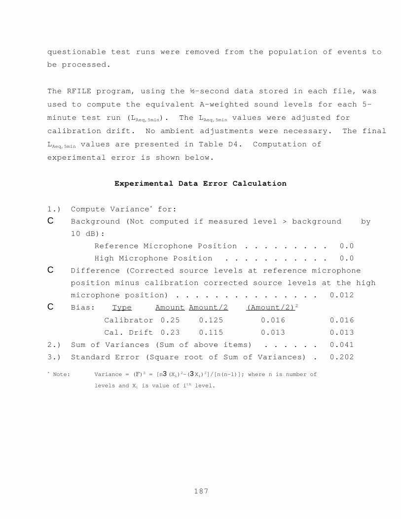
187
questionable test runs were removed from the population of events tobe processed.
The RFILE program, using the ½-second data stored in each file, was
used to compute the equivalent A-weighted sound levels for each 5-
minute test run (LAeq,5min). The LAeq,5min values were adjusted for
calibration drift. No ambient adjustments were necessary. The final
LAeq,5min values are presented in Table D4. Computation of
experimental error is shown below.
Experimental Data Error Calculation
1.) Compute Variance* for:C Background (Not computed if measured level > background by
10 dB):Reference Microphone Position . . . . . . . . . 0.0High Microphone Position . . . . . . . . . . . 0.0
C Difference (Corrected source levels at reference microphoneposition minus calibration corrected source levels at the highmicrophone position) . . . . . . . . . . . . . . . 0.012
C Bias: Type Amount Amount/2 (Amount/2)2
Calibrator 0.25 0.125 0.016 0.016 Cal. Drift 0.23 0.115 0.013 0.013
2.) Sum of Variances (Sum of above items) . . . . . . 0.0413.) Standard Error (Square root of Sum of Variances) . 0.202
* Note: Variance = (F)2 = [n3(Xi)2-(3Xi)2]/[n(n-1)]; where n is number of
levels and Xi is value of ith level.

188
Table D4. Calibration corrected LAeq,5min data.
Test
Run #
Start
Time
REF HIGH MID LOW
1 9:00 80.65 79.30 72.50 65.65
2 9:10 80.15 78.90 71.60 64.95
3 9:20 80.05 78.80 71.40 64.75
4 9:30 80.55 79.30 71.80 64.15
5 9:40 80.25 79.10 71.50 64.85
6 9:50 80.15 79.00 71.20 64.75
7 10:00 80.05 78.80 71.40 64.65
8 10:10 80.55 79.10 71.10 64.25
9 10:20 80.15 78.80 71.10 64.45
10 10:30 80.55 79.20 71.50 64.85
11 11:00 81.15 79.95 73.25 64.75
12 11:10 81.55 80.25 74.35 64.15
13 11:20 80.95 79.45 72.35 64.85
14 11:30 80.75 79.35 72.05 64.75
15 11:40 80.95 79.65 72.75 64.65
16 11:50 80.75 79.45 72.45 64.25
17 12:00 80.95 79.55 72.45 64.45
18 12:10 80.25 79.15 72.15 64.85
19 12:20 - - - -
20 12:30 81.25 80.05 72.95 66.00
21 13:30 81.20 80.00 72.85 66.15
22 13:40 81.30 80.00 72.75 65.95
23 13:50 81.50 80.30 73.35 66.65
24 14:00 - - - -
25 14:10 - - - -
26 14:20 - - - -
27 14:30 80.80 79.50 72.35 65.75
28 14:40 81.80 80.50 73.15 66.75
29 14:50 81.20 80.10 72.85 66.15
30 15:00 81.40 80.30 73.15 66.45
(-) Denotes test run was removed from the population of events to be
analyzed (See Section D.7 for an explanation).

189
REFERENCES
1. Hawks, N.F. Transportation Research Circular.
Washington, DC: Transportation Research Board, February
1985.
2. Barry, T.M. and J.A. Regan. FHWA Highway Traffic Noise
Prediction Model. Report No. FHWA-RD-77-108.
Washington, DC: Federal Highway Administration, December
1978.
3. Anderson, G.S., Lee, C.S., Fleming, G.G., and Menge, C.W.
“FHWA Traffic Noise Model (FHWA TNM®), Version 1.0: User's
Guide.” Report No. FHWA-PD-96-009. Cambridge, MA: John
A. Volpe National Transportation Systems Center, (to be
published).
4. Fleming, G.G., Rapoza, A.S., and Lee C.S. Development of
the Reference Energy Mean Emission Level Data Base for
the FHWA Traffic Noise Model (FHWA TNM®), Version 1.0.
Report No. FHWA-PD-96-008. Cambridge, MA: John A. Volpe
National Transportation Systems Center, November 1995.
5. "Acoustical Terminology." American National Standard,
ANSI S1.1-1994. New York: American National Standards
Institute, 1994.
6. "Methods for Determination of Insertion Loss of Outdoor
Noise Barriers." American National Standard, ANSI S12.8-
1987. New York: American National Standards Institute,1987 (Updated version to be published).

190
7. "Procedures for Outdoor Measurement of Sound PressureLevel." American National Standard, ANSI Standard
S12.18-1994. New York: American National Standards
Institute, 1994.
8. Johnson, D.L., Marsh, A.H., and Harris, C.M. "Acoustical
Measurement Instruments." Handbook of Acoustical
Measurements and Noise Control. New York: Columbia
University, 1991.
9. "Specification for Sound Level Meters." American
National Standard, ANSI Standard S1.4-1983 (R 1990). New
York: American National Standards Institute, 1990.
10. Peterson, A., Gross, E. Handbook of Noise Measurement.
Concord, MA: General Radio Company, 1963.
11. Rickley, E.J., Ingard, U., Cho, Y.C., and Quinn, R.W.
Roadside Barrier Effectiveness: Noise Measurement
Program. Report No. NHTSA-78-24. John A. Volpe National
Transportation Systems Center, 1978.
12. Condensor Microphones and Microphone Preamplifiers.
Denmark: Brüel & Kjær Instruments, Inc., May 1977.
13. Broch, J.T. Acoustic Noise Measurements. Denmark: Brüel& Kjær Instruments, Inc., June 1975.
14. “Electroacoustics, Instruments for measurement of
aircraft noise - Performance requirements for systems to
measure one-third-octave-band sound pressure levels in
noise certification of transport-category aeroplanes.”
191
International Electrotechnical Commission Standard, IECDraft Standard 1265. Denmark: International
Electrotechnical Commission, 1993.
15. "Method for Calibration of Microphones." American
National Standard, ANSI Standard S1.10-1966 (R 1986).
New York: American National Standards Institute, 1986.
16. "Methods for Measurement of Sound Pressure Levels."
American National Standard, ANSI Standard S1.13-1995.
New York: American National Standards Institute, 1995.
17. McGillem, C.D., Cooper, G.R. Continuous and Discrete
Signal and System Analysis. New York: Purdue University,
School of Electrical Engineering, 1984.
18. Stremler, F.G. Introduction to Communication Systems.
Madison, WI: University of Wisconsin, December 1982.
19. "Specification for Octave-Band and Fractional-Octave-Band
Analog and Digital Filters.” American National Standard,
ANSI Standard S1.11-1986 (R 1993). New York: American
National Standards Institute, 1993.
20. Yerges, L.F. Sound, Noise and Vibration Control. New
York: Van Nostrand Reinhold Company, 1978.
21. “Sound Calibrators.” International Electrotechnical
Commission Standard, IEC Standard 942. Denmark:
International Electrotechnical Commission, 1988.

192
22. Hendricks, R.W. Field Evaluation of AcousticalPerformance of Parallel Highway Noise Barriers Along
Route 99 in Sacramento, California. Report No.
FHWA/CA/TL-91/01. Sacramento, CA: California Department
of Transportation, Division of New Technology, Materials
and Research, January 1991.
23. Wayson, R.L. Atmospheric Effects on Traffic Noise
Propagation. Nashville, TN: Vanderbilt University,
August 1989.
24. Hendricks, R.W. California Vehicle Noise Emission
Levels. Report No. FHWA/CA/TL-87/03. Sacramento, CA:
California Department of Transportation, Division of New
Technology, Materials and Research, January 1987.
25. Fleming, G.G. and E.J. Rickley. Performance Evaluation
of Experimental Highway Noise Barriers. Report No. FHWA-
RD-94-093. Cambridge, MA: John A. Volpe National
Transportation Systems Center, April 1994.
26. "Method for Measuring the Influence of Road Surfaces on Traffic
Noise: The Statistical Pass-By Method." International
Organization for Standardization, ISO/CD 11819-1. Delft,
Netherlands: International Organization for Standardization,
November, 1994.
27. “Standard Values of Atmospheric Absorption as a Function of
Temperature and Humidity.” Society of Automotive Engineers
Standard, SAE 866A. New York: Society of Automotive Engineers,
March 1975.

193
28. "Method for Calculation of the Absorption of Sound By theAtmosphere.” American National Standard, ANSI Standard S1.26-
1995. New York: American National Standards Institute, 1995.
29. “Acoustics-Attenuation of Sound During Propagation Outdoors-
Part 1: Calculation of the Absorption of Sound by the
Atmosphere.” International Organization for Standardization,
ISO 9613-1. Geneva, Switzerland: International Organization
for Standardization, 1993.
30. Operator's Manual for Stationary Radar, Model K-15 II Hand Held
Unit. Owensboro, KY: MPH Industries, Inc., 1985.
31. Fleming, G.G. and E.J. Rickley. Parallel Barrier
Effectiveness: Dulles Noise Barrier Project. Report No.
FHWA-RD-90-105. Cambridge, MA: John A. Volpe National
Transportation Systems Center, May 1990.
32. “Field Measurement of Airborne Sound Insulation of
Building Facades and Facade Elements.” American Society
of Testing and Materials, ASTM Standard E 966-84.
Philadelphia, PA: American Society of Testing and
Materials, 1984.
33. "Specification for Personal Noise Dosimeters." American
National Standard, ANSI Standard S1.25-1991. New York:American National Standards Institute, 1991.
34. "Instrumentation Reference Issue." Sound & Vibration. Bay
Village, OH: Acoustical Publications, Inc., March 1996.

194
35. “Fundamentals and Abatement of Highway Traffic Noise: Textbookand Course.” Washington, DC: Federal Highway Administration,
September 1980.
36. Fleming, G.G., Rickley, E.J. Development of National Reference
Energy Mean Emission Levels for Constant-Flow Roadway Traffic:
Test Plan. Letter Report No. DTS-75-HW327-LR2. Cambridge, MA:
John A. Volpe National Transportation Systems Center, September
1993.
37. Private telecommunication with Gilles Daigle. National
Research Council. Ottawa, Canada, February 27, 1996.
38. Hendriks, R.W. and J. Hecker. Parallel Noise Barrier Report: A
Noise Absorptive Demonstration Project. Sacramento, CA:
California Department of Transportation, July 1989.
39. Menge, C.W., Rossano, C.F., Anderson, G.S., Bajdek, C.J.
“FHWA Traffic Noise Model (FHWA TNM®), Version 1.0:
Technical Manual.” Report No. FHWA-PD-96-010.
Cambridge, MA: John A. Volpe National Transportation
Systems Center, (to be published).
40. “Test Method for Sound Absorption and Sound Absorption
Coefficients by the Reverberation Room Method.” American
Society of Testing and Materials, ASTM Standard C 423-
90a. Philadelphia, PA: American Society of Testing andMaterials, 1990.
41. “Test Method for Impedance and Absorption of Acoustical
Materials by the Impedance Tube Method.” American Society of
Testing and Materials, ASTM Standard C 384-95a. Philadelphia,
PA: American Society of Testing and Materials, 1995.
195
42. “Classification for Rating Sound Insulation.” AmericanSociety of Testing and Materials, ASTM Standard E 413-87
(R1994). Philadelphia, PA: American Society of Testing
and Materials, 1987.
43. Reagan, J.A. and C.A. Grant. Highway Construction Noise:
Measurement, Prediction and Mitigation. Report No. FHWA-HEV-2-
77. Washington, DC: Federal Highway Administration, March
1977.
44. "Exterior Sound Level Measurement Procedure for Powered
Mobile Construction Equipment." Society of Automotive
Engineers' Standard, SAE J88a. Society of Automotive
Engineers, 1976.
45. "Sound Levels for Engine Powered Equipment." Society of
Automotive Engineers' Standard, SAE J952b. Society of
Automotive Engineers, 1976.
46. Report of 1977 Symposium on Highway Construction Noise. Report
No. FHWA-TS-77-211. Cranford, NJ: Dames & Moore, 1977.
47. "Measurement of Occupational Noise Exposure." American
National Standard, ANSI Standard S12.19-1996. New York:
American National Standards Institute, (to be published).
48. "Occupational Noise Exposure Standard." Federal Register.
U.S. Department of Labor, Occupational Safety and Health
Administration, Code of Federal Regulations, Title 29, Chapter
XVII, Part 1910. March 1983.

196
49. "Quantities and Procedures for Description and Measurement ofEnvironmental Sound. Part 1." American National Standard,
ANSI Standard S12.9-1988/Part 1 (R 1993). New York: American
National Standards Institute, 1993.
50. “Ground Impedance - Measurement of Ground Impedance.” American
National Standard. New York: American National Standards
Institute, (to be published).
197
INDEX
-A-A-weighting . . . . . . . . . . . . . . . . . . . . . . . . . . . . . . . . . . 5, 29, 44
A-weighted
Sound level . . . . . . . . . . . . . . . . . . . . . . . . . . . . . 11, 58, 116
Sound pressure . . . . . . . . . . . . . . . . . . . . . . . . . . . . . . . . . 9
Sound pressure level . . . . . . . . . . . . . . . . . . . . . . . . . . . 68, 108
Above ground level (AGL) . . . . . . . . . . . . . . . . . . . . . . . . . . . . . . 109
Absorption coefficient . . . . . . . . . . . . . . . . . . . . . . . . . . . . 5, 13, 94
Absorptive barrier . . . . . . . . . . . . . . . . . . . . . . . . . . . . . . . . . 95
Acoustic contamination . . . . . . . . . . . . . . . . . . . . . . . . . . . . . . . 75
Acoustic energy . . . . . . . . . . . . . . . . . . . . . . . . . . . . . . . . 5, 7, 14
Acoustic instrumentation . . . . . . . . . . . . . . . . . . . 17, 33-36, 44, 45, 61, 88
Acoustic integrity of individual events . . . . . . . . . . . . . . . . . . . . . . . 26
Acoustic measurement system . . . . . . . . . . . . . . . . . . . . . . . . . . . 26, 101
Acoustical error . . . . . . . . . . . . . . . . . . . . . . . . . . . . . . 38, 55, 81
Acoustics Facility . . . . . . . . . . . . . . . . . . . . . . . . . . . . . . . . . . 1
Aircraft . . . . . . . . . . . . . . . . . . . . . . . . . . . . . . . . . . . . 22, 31
AGL (See Above ground level)
Aliased frequency components . . . . . . . . . . . . . . . . . . . . . . . . . . . . 25
Ambient noise . . . . . . . . . . . . . . . . . . . . . . . . . . . . 5, 62, 89, 103, 113
American National Standards Institute (See ANSI)
American Society of Testing and Materials (See ASTM)
Amplifier . . . . . . . . . . . . . . . . . . . . . . . . . . . . . . . . . . . . 27, 44
Anemometer . . . . . . . . . . . . . . . . . . . . . . . . . . . . . . . . . . . . . 36
ANSI S1.4 - 1983 . . . . . . . . . . . . . . . . . . . . . . . . . . . . . . 18, 27, 31
ANSI S12.8 - 1987 . . . . . . . . . . . . . . . . . . . . . . . . . . . . . . . . . . 79
ANSI S12.9 - 1988 . . . . . . . . . . . . . . . . . . . . . . . . . . . . . . . . 59, 86
ANSI S1.10 - 1986 . . . . . . . . . . . . . . . . . . . . . . . . . . . . . . . . . . 23
ANSI S1.11 - 1986 . . . . . . . . . . . . . . . . . . . . . . . . . . . . . . . . . . 28
ANSI S1.13 - 1971 . . . . . . . . . . . . . . . . . . . . . . . . . . 24, 34, 59, 86, 112
ANSI S12.18 - 1994 . . . . . . . . . . . . . . . . . . . . . . . . . . . . . . . . . 37
ANSI S12.19 - 1996 . . . . . . . . . . . . . . . . . . . . . . . . . . . . . . 115, 117
ANSI S1.25 - 1991 . . . . . . . . . . . . . . . . . . . . . . . . . . . . . . . . 44, 115
ANSI S1.40 - 1984 . . . . . . . . . . . . . . . . . . . . . . . . . . . . . . . . . . 33

198
Antennae . . . . . . . . . . . . . . . . . . . . . . . . . . . . . . . . . . . . . . 34
Anti-alias filter . . . . . . . . . . . . . . . . . . . . . . . . . . . . . . . 5, 6, 25
Artificial noise source . . . . . . . . . . . . . . . . . . . . . . . . . . . 5, 43, 110
ASTM C385-95a . . . . . . . . . . . . . . . . . . . . . . . . . . . . . . . . . . . . 94
ASTM C423-90a . . . . . . . . . . . . . . . . . . . . . . . . . . . . . . . . 13, 94, 95
ASTM E413-87 . . . . . . . . . . . . . . . . . . . . . . . . . . . . . . . . . . . . 95
ASTM E966-84 . . . . . . . . . . . . . . . . . . . . . . . . . . . . . . . . . . . . 107
Atmospheric
Absorption . . . . . . . . . . . . . . . . . . . . . . . . . . . . . . . . . . 39
Conditions . . . . . . . . . . . . . . . . . . . . . . . . . . . . . . . . . . 20
Equivalence . . . . . . . . . . . . . . . . . . . . . . . . . . . . . . . . . 80
Audio tape recorders
Digital . . . . . . . . . . . . . . . . . . . . . . . . . . . . . . . . . . . 32
Automobile . . . . . . . . . . . . . . . . . . . . . . . . . . . . . 22, 68, 72, 76, 159
-B-Background noise . . . . . . . . . . . . . . . . . . . . . . . . . . . . . . . . . 2, 6
Barrier . . . . . . . . . . . . . . 2, 11, 12, 15, 53, 65, 75, 79, 80, 83-85, 90-95, 125
Absorptive . . . . . . . . . . . . . . . . . . . . . . . . . . . . . . . . . . 95
Characteristics . . . . . . . . . . . . . . . . . . . . . . . . . . . . . . . 125
Insertion loss . . . . . . . . . . . . . . . 1, 3, 37, 42, 79, 82, 85, 89, 91, 92
Parallel . . . . . . . . . . . . . . . . . . . . . . . . . . . . . . . . 90, 92-94
Reflective . . . . . . . . . . . . . . . . . . . . . . . . . . . . . . . . 93, 94
Battery . . . . . . . . . . . . . . . . . . . . . . . . . . . . . . . . . . . . . 32, 45
Brüel & Kjær
Model 0237 Windscreen . . . . . . . . . . . . . . . . . . . . . . . . . . . . 35
Building noise reduction . . . . . . . . . . . . . . . . . . . . . . . . . . . 107, 109
Butterworth filter
Type 1-D . . . . . . . . . . . . . . . . . . . . . . . . . . . . . . . . . . . 28
-C-C-weighting . . . . . . . . . . . . . . . . . . . . . . . . . . . . . . . . . . . . . 29
Calibrator . . . . . . . . . . . . . . . . . . . . . . . 2, 3, 33, 43, 44, 107, 110, 111
California REMEL study . . . . . . . . . . . . . . . . . . . . . . . . . . . . . . . 157
Caltrans . . . . . . . . . . . . . . . . . . . . . . . . . . . . . . . . . . . . . . 157
Characteristics of measurement system . . . . . . . . . . . . . . . . . . . . . . . . 28

199
Characteristics of source
Spectral . . . . . . . . . . . . . . . . . . . . . . . . . . . . . . . . . . . 10
Classes of
Cloud cover . . . . . . . . . . . . . . . . . . . . . . . . . . . . . . . . . 56
Wind conditions . . . . . . . . . . . . . . . . . . . . . . . . . . . . . . . 38
Cloud Cover . . . . . . . . . . . . . . . . . . . . . . . . . . . . . . . . . . . . . 56
Constant-speed roadway traffic . . . . . . . . . . . . . . . . . . . . . . . . . . . 67
Construction equipment . . . . . . . . . . . . . . . . . . . . . . . . . . . . . 97, 99
Contaminating vehicles . . . . . . . . . . . . . . . . . . . . . . . . . . . . . . . 71
Contamination (See Acoustic contamination)
-D-Datalogging weather station . . . . . . . . . . . . . . . . . . . . . . . . . . . 37, 39
Day-night average sound level (Ldn) . . . . . . . . . . . . . . . . . . . 7, 58, 85, 110
dB . . . . . . . . 6-11, 13, 14, 25, 26, 33-35, 38, 44, 55, 62, 63, 66, 69, 70, 72, 76,
81, 89, 90, 92-95, 99, 103, 104, 108, 113, 114, 116, 158, 159
Safety margin of 10 . . . . . . . . . . . . . . . . . . . . . . . . . . . . . 25
Dense-Graded Asphaltic Concrete (DGAC) . . . . . . . . . . . . . . . . . . . . . . . 76
Dew sensor . . . . . . . . . . . . . . . . . . . . . . . . . . . . . . . . . . . . . 32
Diaphragm . . . . . . . . . . . . . . . . . . . . . . . . . . . . . . . . . . . . . . 20
Digital recorder . . . . . . . . . . . . . . . . . . . . . . . . . . . . . . . . 23, 25
Digitization process . . . . . . . . . . . . . . . . . . . . . . . . . . . . . 5, 6, 25
Directivity . . . . . . . . . . . . . . . . . . . . . . . . . . . . . . . . . . 5, 56, 82
Documentation
Report . . . . . . . . . . . . . . . . . . . . . . . . . . . . . . . . . . . . 123
Doppler-radar gun . . . . . . . . . . . . . . . . . . . . . . . . . . . . . . . . . . 40
Dosimeter . . . . . . . . . . . . . . . . . . . . . . . . . . . . . . . . . 44, 116, 117
Dry bulb temperature . . . . . . . . . . . . . . . . . . . . . . . . . . . . . . . . 127
Dynamic range . . . . . . . . . . . . . . . . . . . . . . . . . . . . . . . . . . . 9, 26
-E-Earthwork . . . . . . . . . . . . . . . . . . . . . . . . . . . . . . . . . . . . . . 97
Edge-diffraction bias adjustment . . . . . . . . . . . . . . . . . . . . . . . . . . 90
Electric cars . . . . . . . . . . . . . . . . . . . . . . . . . . . . . . . . . . 68, 76

200
Electrical
Capacitance . . . . . . . . . . . . . . . . . . . . . . . . . . . . . . . . . 20
Characteristics of tape recorder . . . . . . . . . . . . . . . . . . . . . . . 24
Noise . . . . . . . . . . . . . . . . . . . . . . . . . . . . . . . . . . . 5, 19
Signals . . . . . . . . . . . . . . . . . . . . . . . . . . . . . . . . . . . 18
Electronic noise floor . . . . . . . . . . . . . . . . . . . . . . 34, 73, 87, 101, 112
Elevation view . . . . . . . . . . . . . . . . . . . . . . . . . . . . . . . . . . . 124
Emission levels . . . . . . . . . . . . . . . . . . . . . . . . . . . . . 65, 67, 72, 98
Energy residuals . . . . . . . . . . . . . . . . . . . . . . . . . . . . . . . . . . 78
Engine/exhaust term . . . . . . . . . . . . . . . . . . . . . . . . . . . . . . . . . 78
Equivalent sound level (LAeq) . . . . . . 9, 14, 28, 58, 85, 100, 103-105, 117, 119, 120
30-second . . . . . . . . . . . . . . . . . . . . . . . . . . . . . . . . . . 100
Event quality . . . . . . . . . . . . . . . . . . . . . . . . . . . . . . . . . . . . 70
Exchange rate . . . . . . . . . . . . . . . . . . . . . . . . . . . . . . . . . . . . . 9
Existing-noise measurements . . . . . . . . . . . . . . . . . . . . . . . . . . . . . 53
Existing-noise exposure level (Lden) . . . . . . . . . . . . . . . . . . 6, 58, 85, 111
Exponential time-averaging exponential time-averaging . . . . . . . . . . . . . . 31, 32
Exterior measurements . . . . . . . . . . . . . . . . . . . . . . . . . . . . . 108, 109
-F-Fast-scale response . . . . . . . . . . . . . . . . . . . . . . . . . . . . . . . . . 11
Federal Highway Administration (FHWA) . . . . . . . . . . . . . . . . . . . . . . . 1, 2
FHWA (See Federal Highway Administration)
FHWA Traffic Noise Model (FHWA TNM) . . . . . . . . . . . . 2, 65, 67, 68, 72, 75, 78, 80
Vehicle type . . . . . . . . . . . . . . . . . . . . . . . . . . . . . . . . . 78
FHWA TNM (See FHWA Traffic Noise Model)
Filter
Anti-alias . . . . . . . . . . . . . . . . . . . . . . . . . . . . . . . . . . 25
Butterworth, Type 1-D . . . . . . . . . . . . . . . . . . . . . . . . . . . . 28
Shape algorithms . . . . . . . . . . . . . . . . . . . . . . . . . . . . . . . 28
Free Field . . . . . . . . . . . . . . . . . . . . . . . . . . . . . . . . . . . . . 10
-G-Gain Control . . . . . . . . . . . . . . . . . . . . . . . . . . . . . . . . . . . . 31
Generic Measurement Instrumentation Setup . . . . . . . . . . . . . . . . . . . . . . 17

201
Geometric
Characteristics . . . . . . . . . . . . . . . . . . . . . . . . . . . . . 79, 108
Equivalence . . . . . . . . . . . . . . . . . . . . . . . . . . . . . . . . . 79
Geometry . . . . . . . . . . . . . . . . . . . . . . . . . . . . . . . . . . 54, 80, 81
GLR (See Graphic level recorder)
Graphic level recorder (GLR) . . . . . . . . . . . . . . . . . . . . . . 18, 26, 47, 69
Plot . . . . . . . . . . . . . . . . . . . . . . . . . . . . . . . . . . . . . 26
Grazing incidence . . . . . . . . . . . . . . . . . . . . . . . . . . . . . . . 21-23, 67
Ground
Attenuation . . . . . . . . . . . . . . . . . . . . . . . . . . . . . . . . . 10
Hard . . . . . . . . . . . . . . . . . . . . . . . . . . . . . . . . . . . . . 10
Impedance . . . . . . . . . . . . . . . . . . . . . . . . . . . . . . . . . . 10
Soft . . . . . . . . . . . . . . . . . . . . . . . . . . . . . . . . . . . . . 13
Surface characterization . . . . . . . . . . . . . . . . . . . . . . . . . . . 123
-H-Hard ground . . . . . . . . . . . . . . . . . . . . . . . . . . . . . . . . . . . . . 11
Headphones . . . . . . . . . . . . . . . . . . . . . . . . . . . . . . . . . . . 34, 44
Heavy truck . . . . . . . . . . . . . . . . . . . . . . . . . . . . . . . . . 68, 72, 157
Highway noise barriers . . . . . . . . . . . . . . . . . . . . . . . . . . . . . . . 65
Highway noise prediction models . . . . . . . . . . . . . . . . . . . . . . . . . 65, 88
Humidity . . . . . . . . . . . . . . . . . . . . . . . . . . . . . . . . . . . . 32, 39
Hygrometer . . . . . . . . . . . . . . . . . . . . . . . . . . . . . . . . . . . . . 38
-I-IEC 942 . . . . . . . . . . . . . . . . . . . . . . . . . . . . . . . . . . . . . . . 33
IEC 1265 . . . . . . . . . . . . . . . . . . . . . . . . . . . . . . . . . . . . 24, 31
Impedance Tube Method . . . . . . . . . . . . . . . . . . . . . . . . . . . . . . . . 93
Incidence
Angle . . . . . . . . . . . . . . . . . . . . . . . . . . . . . . . . . . . . 36
Grazing . . . . . . . . . . . . . . . . . . . . . . . . . . . . . . . . 21-23, 67
Normal . . . . . . . . . . . . . . . . . . . . . . . . . . . . . . . . . . . 21-23
Input gain control . . . . . . . . . . . . . . . . . . . . . . . . . . . . . . . . . 31
Insertion loss . . . . . . . . . . . . . . . . . . . . . . . . . . . . . . . . . 11, 91
Interior measurements . . . . . . . . . . . . . . . . . . . . . . . . . . . . . . . . 107
Internal noise . . . . . . . . . . . . . . . . . . . . . . . . . . . . . . . . . . . 107

202
International Electrotechnical Commission (See IEC)
-L-Ladj . . . . . . . . . . . . . . . . . . . . . . . . . . . . . 63, 70, 71, 90, 104, 114
LAE (See Sound exposure level)
Laeq (See Equivalent sound level)
LAFmx (See Maximum sound level)
LASmx (See Maximum sound level)
Land-use planning . . . . . . . . . . . . . . . . . . . . . . . . . . . . . . 58, 85, 111
Lden (See Community-noise exposure level)
Ldn (See Day-night average sound level)
Level-mean
Emission level equation . . . . . . . . . . . . . . . . . . . . . . . . . 76, 77
Energy-mean adjustment factor . . . . . . . . . . . . . . . . . . . . . . . . 77
Regression . . . . . . . . . . . . . . . . . . . . . . . . . . . . . . . . . . 77
Light sensor . . . . . . . . . . . . . . . . . . . . . . . . . . . . . . . . . . . . 41
Line source . . . . . . . . . . . . . . . . . . . . . . . . . . . . . . . . . . . 11, 22
Line-of-sight . . . . . . . . . . . . . . . . . . . . . . . . . . . . . . 66, 92, 98, 108
Long-term noise . . . . . . . . . . . . . . . . . . . . . . . . . . . . . . . 58, 85, 110
Loudspeaker . . . . . . . . . . . . . . . . . . . . . . . . . . . . . . . . 43, 107, 110
Position . . . . . . . . . . . . . . . . . . . . . . . . . . . . . . . . . . . 110
Source . . . . . . . . . . . . . . . . . . . . . . . . . . . . . . . . . . . . 43
Low-pass filter . . . . . . . . . . . . . . . . . . . . . . . . . . . . . . . . . . 5, 31
Low-speed automobiles . . . . . . . . . . . . . . . . . . . . . . . . . . . . . . . . 70
Lower bound to insertion loss . . . . . . . . . . . . . . . . . . . . . . . . . . . . 11
-M-Maximum sound level (LAFmx or LASmx) . . . . . . . . . . 11, 14, 69-71, 75, 76, 100, 102,
119, 157, 158
Measurement system . . . . . . . . . . . . . . . . . . . . . . . . . . . . . . . . . 26
Medium truck . . . . . . . . . . . . . . . . . . . . . . . . . . . . . . . . . . . . 68
Meteorological . . . . . . . . . . . . . . . . . . . . . . . . . . . . . . . . 54, 79-81
Conditions . . . . . . . . . . . . . . . 36, 54, 58, 73, 81, 85, 87, 101, 112, 124
Data . . . . . . . . . . . . . . . . . . . . . . . . . . . . . . . . . . . 58, 85
Instrumentation . . . . . . . . . . . . . . . . . . . . . . . . . . . . . 36, 50

203
Microphone . . . . . . . . 18-23, 27, 32, 34, 35, 40, 44, 56, 57, 60, 63, 66, 75, 82-84,
87-90, 98, 101, 108, 109, 112, 113, 116, 117, 119, 157, 158
1-inch diameter . . . . . . . . . . . . . . . . . . . . . . . . . . . . . . . 21
Backplate . . . . . . . . . . . . . . . . . . . . . . . . . . . . . . . . . . 20
Brüel & Kæjr 4155 . . . . . . . . . . . . . . . . . . . . . . . . . . . . . . 128
Characteristics . . . . . . . . . . . . . . . . . . . . . . . . . . . . . . . 18
Condensor . . . . . . . . . . . . . . . . . . . . . . . . . . . . . . . . 19, 20
Corrections . . . . . . . . . . . . . . . . . . . . . . . . . . . . . . . . . 23
Electret . . . . . . . . . . . . . . . . . . . . . . . . . . . . . . . 20, 21, 23
Diameter . . . . . . . . . . . . . . . . . . . . . . . . . . . . . . . . . . . 21
Diaphragm . . . . . . . . . . . . . . . . . . . . . . . . . . . . . 20-22, 35, 67
Dosimeters . . . . . . . . . . . . . . . . . . . . . . . . . . . . . . . . . . 117
Height . . . . . . . . . . . . . . . . . . . . . . . . . . . . . . . . . . 57, 84
Incidence . . . . . . . . . . . . . . . . . . . . . . . . . . . . . . . . 21, 22
Location . . . . . . . . . . . . . . . . . . . . . 56, 57, 67, 82, 84, 85, 99, 108
Position . . . . . . . . . . . . . . . . . . . . . . . . . . . . . . . 19, 99, 108
Preamplifier . . . . . . . . . . . . . . . . 18, 20, 27, 44, 58, 69, 85, 100, 111
Reference . . . . . . . . . . . . . . . . . . . . . . . . . . . . . . . . 56, 82
Sensitivity of . . . . . . . . . . . . . . . . . . . . . . . . . . . . . . . . 21
Simulator . . . . . . . . . . . . . . . . . . . . . . . . . . . . 34, 49, 58, 128
Size . . . . . . . . . . . . . . . . . . . . . . . . . . . . . . . . . . . . . 21
System . . . . . . . . . . . . . . . . . . . . . . . . . . 18, 19, 21, 45, 67, 111
Minimum number of samples . . . . . . . . . . . . . . . . . . . . . . . . . . . . . . 72
Minimum separation distance . . . . . . . . . . . . . . . . . . . . . . . . . . . 71, 159
Motor home . . . . . . . . . . . . . . . . . . . . . . . . . . . . . . . . . 68, 72, 76
Motorcycle . . . . . . . . . . . . . . . . . . . . . . . . . . . . . . . . . . . 72, 76
-N-Near-field . . . . . . . . . . . . . . . . . . . . . . . . . . . . . . . . . . . . . 12
Effects . . . . . . . . . . . . . . . . . . . . . . . . . . . . . . . . . . . 82
Noise
Barrier . . . . . . . . . . . . . . . . . . . . . . . . . . . . . . . . . . . 12
Contamination . . . . . . . . . . . . . . . . . . . . . . . . . . . . . . . . 12
Descriptors . . . . . . . . . . . . . . . . . . . . . . 58, 68, 85, 100, 110, 117
Dosimeter (See Dosimeter)
Reduction Coefficient (NRC) . . . . . . . . . . . . . . . . . . . . . 12, 94, 123

204
-O-Occupational Safety & Health Administration (OSHA) . . . . . . . . . . 44, 115-117, 120
Octave-band
Analyzers, use of . . . . . . . . . . . . . . . . . . . . . . . . . . . . . . 28
Filters . . . . . . . . . . . . . . . . . . . . . . . . . . . . . . . . . . . 28
One-third octave-band . . . . . . . . . . . . . . . . . . . . . . . . . . . . . . 30, 44
Analysis . . . . . . . . . . . . . . . . . . . . . . . . . . . . . . . . . . . 13
Analyzer . . . . . . . . . . . . . . . . . . . . . . . . . . . . . 18, 28, 29, 48
Orange highway cones . . . . . . . . . . . . . . . . . . . . . . . . . . . . . . . . 74
OSHA (See Occupational Safety & Health Administration)
Outdoor-indoor noise reduction . . . . . . . . . . . . . . . . . . . . . . . . . . . 107
-P-Parallel barrier . . . . . . . . . . . . . . . . . . . . . . . . . . . . . . . . . . 92
Pavement type . . . . . . . . . . . . . . . . . . . . . . . . . . . . . . . . . 130, 131
Penalty
5-db . . . . . . . . . . . . . . . . . . . . . . . . . . . . . . . . . . . . . . 6
10-db . . . . . . . . . . . . . . . . . . . . . . . . . . . . . . . . . . . 6, 7
Pink noise . . . . . . . . . . . . . . . . . . . . . . . . . . . . . . . . . . . . . 13
Generator . . . . . . . . . . 35, 49, 58, 60, 69, 73, 86, 87, 100, 101, 111, 112
Plan view . . . . . . . . . . . . . . . . . . . . . . . . . . . . . . . . . . . . . . 121
Pneumatic line . . . . . . . . . . . . . . . . . . . . . . . . . . . . . . . . . . 41-43
Point source . . . . . . . . . . . . . . . . . . . . . . . . . . . . . . . . . . 13, 22
Point-source measurements . . . . . . . . . . . . . . . . . . . . . . . . . . . . . . 22
Portland Cement Concrete (PCC) . . . . . . . . . . . . . . . . . . . . . . . . . . . 76
Preamplifier . . . . . . . . . . . . . . . . . . . . . . . . . . . . . . . . 18, 27, 44
Psychrometer . . . . . . . . . . . . . . . . . . . . . . . . . . . . . . . . . . 38, 39
-R-Radar gun . . . . . . . . . . . . . . . . . . . . . . . . . . . . . . . . . . . . 40, 74
Radio frequency interference . . . . . . . . . . . . . . . . . . . . . . . . . . . . 18
Random-noise generator . . . . . . . . . . . . . . . . . . . . . . 60, 73, 87, 101, 112
Recording
Instrumentation . . . . . . . . . . . . . . . . 19, 26, 33, 58, 69, 85, 100, 111
System . . . . . . . . . . . . . . . . . . . . . . . . . . . . . . . . . . 23, 46
Reflective barrier . . . . . . . . . . . . . . . . . . . . . . . . . . . . . . . 93, 94

205
Reference Energy Mean Emission Level (REMEL) . . . . . . . . . . . . . . . . . . 76, 157
Data Base . . . . . . . . . . . . . . . . . . . . . . . . . . . . . . . . . 2, 65
Barrier . . . . . . . . . . . . . . . . . . . . . . . . . . . . . . . . . . . 92
Measurements . . . . . . . . . . . . . . . . . . . . . . . . . . . . . . . . . 68
Regression equations . . . . . . . . . . . . . . . . . . . . . . . . . . . . . 75
State-specific . . . . . . . . . . . . . . . . . . . . . . . . . . . . . . 75, 76
Studies . . . . . . . . . . . . . . . . . . . . . . . . . . . . . . . . . . . 77
Reference microphone . . . . . . . . . . . . . . 56, 57, 60, 62, 63, 82, 83, 87-90, 112
Relative humidity . . . . . . . . . . . . . . . . . . . . . . . . . . . . . . . . . . 125
REMEL (See Reference Energy Mean Emission Level)
Report documentation . . . . . . . . . . . . . . . . . . . . . . . . . . . . . . . . 123
Reverberation Room Method . . . . . . . . . . . . . . . . . . . . . . . . . . . . . . 94
Rule-of-thumb . . . . . . . . . . . . . . . . . . . . . . . . . . . . 10, 12, 13, 39, 91
-S-Sabine absorption coefficient ("sab) . . . . . . . . . . . . . . . . . . . . . . 12, 94
Sampling period . . . . . . . . . . . . . . . . . . . . . . . . 59, 69, 86, 101, 111, 118
Sensitivity
Human ear . . . . . . . . . . . . . . . . . . . . . . . . . . . . . . . . . . 28
Instrumentation . . . . . . . . . . . . . . . . . . . . . . . . . . . . . . . 32
Response . . . . . . . . . . . . . . . . . . . . . . . . . . . . . . . . . . . 19
Separation-distance criteria . . . . . . . . . . . . . . . . . . . . . . . 74, 157, 158
Signal-to-noise ratio . . . . . . . . . . . . . . . . . . . . . . . . . . . . . . . . 24
Site
Characteristics . . . . . . . . . . . . . . . . . . . . . . . 53, 65, 81, 98, 107
Selection . . . . . . . . . . . . . . . . . . . . . . . 53, 65, 80, 98, 107, 116
Sketches . . . . . . . . . . . . . . . . . . . . . . . . . . . . . . . . . . . 123
Sling Psychrometer . . . . . . . . . . . . . . . . . . . . . . . . . . . . . . . 38, 39
SLM (See Sound level meter)
Slow-scale response . . . . . . . . . . . . . . . . . . . . . . . . . . . . . . . . . 11
Soft ground . . . . . . . . . . . . . . . . . . . . . . . . . . . . . . . . . . . . . 13
Solar radiation . . . . . . . . . . . . . . . . . . . . . . . . . . . . . . . . . . . 39
Sound absorption coefficient . . . . . . . . . . . . . . . . . . . . . . . . 13, 94, 95
Sound exposure level (LAE) . . . . . . . . . . . . . . 6, 7, 9, 14, 28, 58, 85, 111, 116
Sound Level Meter (SLM) . . . . . . . . . . . . . . . . . . . . . . . . 27, 29, 117, 118
Sound Pressure Level (SPL) . . . . . . . . . . . . . . . . . . . . . . . . . . 5, 10, 14

206
Sound Transmission Class (STC) . . . . . . . . . . . . . . . . . . . . . . . 15, 95, 125
Source description . . . . . . . . . . . . . . . . . . . . . . . . . . . . . . . . . 123
SPL (See Sound pressure level)
State-specific emission levels . . . . . . . . . . . . . . . . . . . . . . . . . 75, 76
Statistical
Confidence . . . . . . . . . . . . . . . . . . . . . . . . . . . . . . . . . . 72
Reliability of measurement results . . . . . . . . . . . . . . . . . . 59, 86, 112
STC (See Sound Transmission Class)
Stopwatch . . . . . . . . . . . . . . . . . . . . . . . . . . . . . . . . . . . . . . 41
-T-Tachometer . . . . . . . . . . . . . . . . . . . . . . . . . . . . . . . . . . . . . 43
Temperature
Average . . . . . . . . . . . . . . . . . . . . . . . . . . . . . . . . . 55, 82
Thermometer . . . . . . . . . . . . . . . . . . . . . . . . . . . . . . . . . . . 38, 39
Time-history . . . . . . . . . . . . . . . . . . . . . . . . . . . . . . . . . . . . 69
TNM (See FHWA Traffic Noise Model)
Traffic
Conditions . . . . . . . . . . . . . . . . . . . . . . . . . . . 54, 56, 57, 79-82
Counts . . . . . . . . . . . . . . . . . . . . . . . . . . . . . . . . . . . . 43
Data . . . . . . . . . . . . . . . . . . . . . . . . . . . . . . . . . . . 61, 87
Equivalence . . . . . . . . . . . . . . . . . . . . . . . . . . . . . . . . . 80
Flow . . . . . . . . . . . . . . . . . . . . . . . . . . . . . . . . . . . . . 40
Counting Device . . . . . . . . . . . . . . . . . . . . . . . . . 51, 58, 86, 111
-U-Useable Frequency Range . . . . . . . . . . . . . . . . . . . . . . . . . . . . . . . 21
User-defined Vehicle . . . . . . . . . . . . . . . . . . . . . . 65, 67, 68, 75, 76, 78
-V-Vector Component of Wind Velocity . . . . . . . . . . . . . . . . . . . . . . . . . . 38
Vehicle
Interrupted-flow traffic . . . . . . . . . . . . . . . . . . . . . . . . . . . 67
Mix . . . . . . . . . . . . . . . . . . . . . . . . . . . . . . . . . . . . . 43
Noise emission level . . . . . . . . . . . . . . . . . . . . . . . . . . . 65, 67
Pass-bys . . . . . . . . . . . . . . . . . . . . . . . . . . . . 6, 7, 58, 85, 110
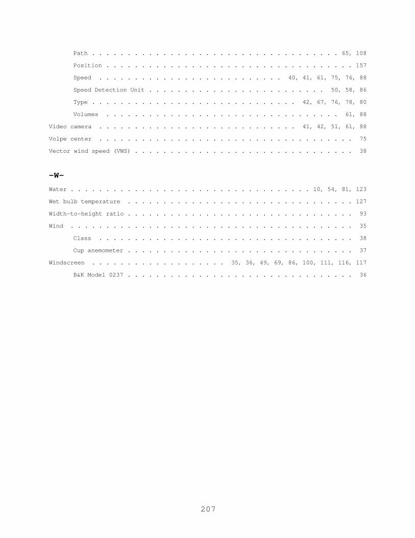
207
Path . . . . . . . . . . . . . . . . . . . . . . . . . . . . . . . . . . . 65, 108
Position . . . . . . . . . . . . . . . . . . . . . . . . . . . . . . . . . . . 157
Speed . . . . . . . . . . . . . . . . . . . . . . . . . . 40, 41, 61, 75, 76, 88
Speed Detection Unit . . . . . . . . . . . . . . . . . . . . . . . . . 50, 58, 86
Type . . . . . . . . . . . . . . . . . . . . . . . . . . . . . 42, 67, 76, 78, 80
Volumes . . . . . . . . . . . . . . . . . . . . . . . . . . . . . . . . . 61, 88
Video camera . . . . . . . . . . . . . . . . . . . . . . . . . . . . 41, 42, 51, 61, 88
Volpe center . . . . . . . . . . . . . . . . . . . . . . . . . . . . . . . . . . . . 75
Vector wind speed (VWS) . . . . . . . . . . . . . . . . . . . . . . . . . . . . . . . 38
-W-Water . . . . . . . . . . . . . . . . . . . . . . . . . . . . . . . . . . 10, 54, 81, 123
Wet bulb temperature . . . . . . . . . . . . . . . . . . . . . . . . . . . . . . . . 127
Width-to-height ratio . . . . . . . . . . . . . . . . . . . . . . . . . . . . . . . . 93
Wind . . . . . . . . . . . . . . . . . . . . . . . . . . . . . . . . . . . . . . . . 35
Class . . . . . . . . . . . . . . . . . . . . . . . . . . . . . . . . . . . . 38
Cup anemometer . . . . . . . . . . . . . . . . . . . . . . . . . . . . . . . . 37
Windscreen . . . . . . . . . . . . . . . . . . . 35, 36, 49, 69, 86, 100, 111, 116, 117
B&K Model 0237 . . . . . . . . . . . . . . . . . . . . . . . . . . . . . . . . 36

1 Rev2011-07-13
Traffic Noise Study Report Format Guide for Arizona Department of Transportation Projects
Introduction The Arizona Department of Transportation (ADOT) seeks uniformity and standardization in terms of quality and completeness in all Noise Study Reports submitted by consultants. These guidelines are intended to assist the consultants in achieving those goals, thereby saving time and effort by both ADOT staff and consultants. It should be noted that these are guidelines and are not intended to discourage creativity by the consultant. However, it is imperative that all noise analyses be discussed in advance with ADOT Air and Noise Technical Team Staff. In all cases, ADOT’s goals for its Noise Study Reports are: Conformity with Federal Highway Administration (FHWA) and ADOT Policies
and Practices; Accuracy; Comprehensiveness; Efficiency; Readability Formatting Considerations The report should utilize a twelve-point Arial font and use left margin alignment. Each page should have one-inch margins, and include a left-justified, bold, eight point header denoting the project name followed by report status (see below) and the date of submission. All section headings should be a numbered and/or lettered. Page numbers should be shown at the bottom center. Tables and figures should be utilized to the fullest extent possible, in order to minimize descriptive verbiage. All reports should include a cover page, title page, table of contents, list of tables, and list of figures, and should utilize the most current templates for the cover and title pages, which can be found at www.azdot.gov/environmentalplanning. The submittal number at the bottom of the cover and/or title page should only be used for Draft and Final Draft Noise Reports (see below), not on Final Noise Reports. Report Status and Submission The report status indicates the stage of the report or addendum in the approval process, and should use the following classifications and submission processes: Draft Noise Report –has been submitted for review but not yet approved by
the ADOT Air and Noise Team Final Draft Noise Report – has been approved by the ADOT Air and Noise
Team and is being submitted for FHWA review and/or approval Final Noise Report – has been approved by both the ADOT Air and Noise
Team and FHWA
2 Rev2011-07-13
Not every report will utilize each stage listed above. For example, many reports will proceed directly from Draft Noise Report to Final Noise Report status. Each submittal of a noise report should include an electronic version of the document along with the requested number of hardcopies. Report Sections The recommended sections for Noise Study Reports are: 1. Executive Summary 2. Project Introduction 3. Description of Traffic Noise and Study Procedures 4. Noise Sensitive Land Uses in the Study Area 5. Existing Noise Environment 6. Future Noise Environment and Impact Determination 7. Mitigation Analysis 8. Construction Noise 9. Coordination with Local Governments 10. Conclusion 11. Appendices Section 1: Executive Summary This section should be no longer than two pages, and should include summary discussions of each section as well as a table summarizing any recommended noise abatement measures. Section 2: Project Introduction This section should briefly describe the project, including type, purpose and need, limits, and authority. It should include an overview figure(s) denoting project limits. The project design year, number of lanes, and other designs issues should be discussed, as appropriate. Suggested wording for this section: This study addresses the effects of traffic and construction generated noise that can be expected to occur due to the re-construction [construction, widening, relocation, etc.] of [route] from [project terminus] to [project terminus] in [location], Arizona. [Include additional details as necessary] The project limits are shown in Figure 1. The analysis contained herein was performed in compliance with Regulation 23 CFR 772 and Federal Highway Administration guidelines for the assessment of highway traffic-generated noise. In addition, the analysis was performed and specific abatement considerations were made in accordance with the ADOT Noise Abatement Policy dated [insert NAP effective date].
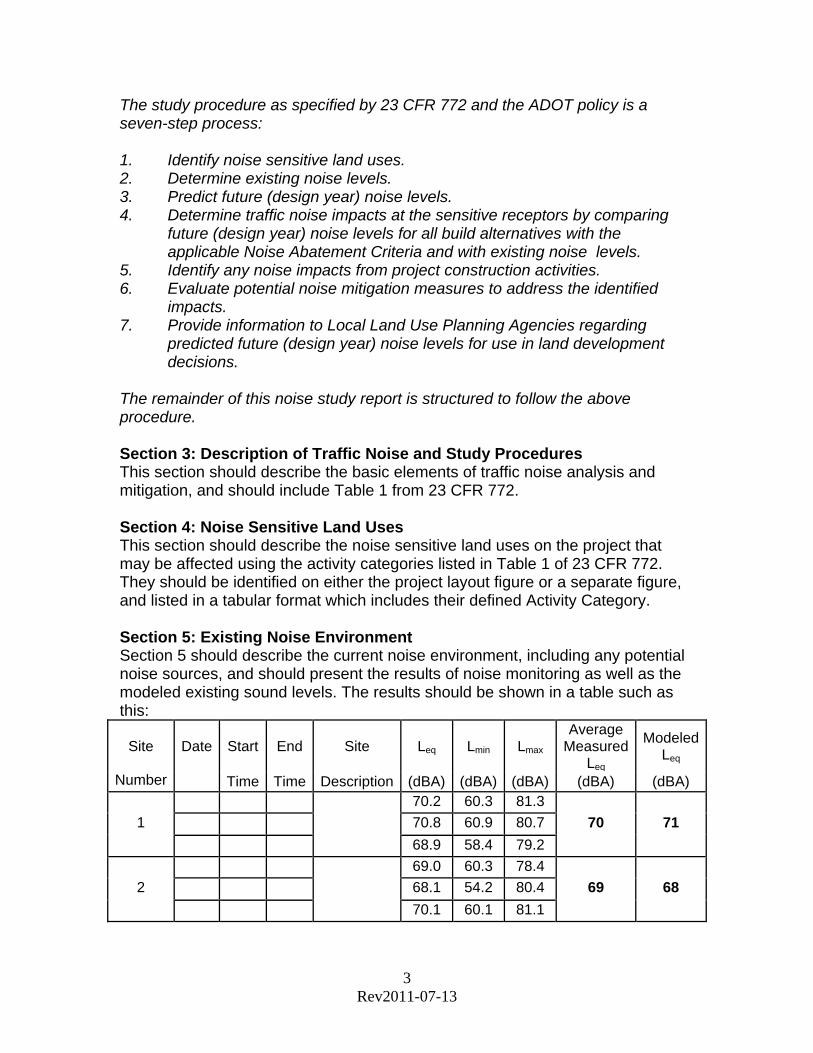
3 Rev2011-07-13
The study procedure as specified by 23 CFR 772 and the ADOT policy is a seven-step process: 1. Identify noise sensitive land uses. 2. Determine existing noise levels. 3. Predict future (design year) noise levels. 4. Determine traffic noise impacts at the sensitive receptors by comparing
future (design year) noise levels for all build alternatives with the applicable Noise Abatement Criteria and with existing noise levels.
5. Identify any noise impacts from project construction activities. 6. Evaluate potential noise mitigation measures to address the identified
impacts. 7. Provide information to Local Land Use Planning Agencies regarding
predicted future (design year) noise levels for use in land development decisions.
The remainder of this noise study report is structured to follow the above procedure. Section 3: Description of Traffic Noise and Study Procedures This section should describe the basic elements of traffic noise analysis and mitigation, and should include Table 1 from 23 CFR 772. Section 4: Noise Sensitive Land Uses This section should describe the noise sensitive land uses on the project that may be affected using the activity categories listed in Table 1 of 23 CFR 772. They should be identified on either the project layout figure or a separate figure, and listed in a tabular format which includes their defined Activity Category. Section 5: Existing Noise Environment Section 5 should describe the current noise environment, including any potential noise sources, and should present the results of noise monitoring as well as the modeled existing sound levels. The results should be shown in a table such as this:
Site Date Start End Site Leq Lmin Lmax Average
Measured Leq
Modeled Leq
Number Time Time Description (dBA) (dBA) (dBA) (dBA) (dBA) 70.2 60.3 81.3
1 70.8 60.9 80.7 70 71
68.9 58.4 79.2
69.0 60.3 78.4
2 68.1 54.2 80.4 69 68
70.1 60.1 81.1

4 Rev2011-07-13
The values shown in the table above are illustrative, to show when they should be rounded off to the nearest whole dBA. Also, Lmin and Lmax are not required, but can be helpful in interpreting the data. Weather and traffic conditions should be included as notes at the bottom of the table. Results should also be discussed in general terms in the report. For example, the following discussion may be used as a guide: In order to document the existing noise environment, a series of field measurements was made in the study area from [month] to [month], 20xx. These measurements were made at [number] representative receiver locations throughout the project corridor. Measurements were made in the [time of day] and each site was measured [number] times; the measured Leq values were then averaged and rounded off to the nearest whole dBA. In order to be acceptable, each of the [number] measurements must be within +/- 3 dBA of each other. The equipment used to conduct the measurements included a Larson-Davis Integrating Sound Level Meter (SLM) Model 824 system [or other]. The procedures and protocols followed are in accordance with Section 4 of the FHWA report Measurement of Highway-Related Noise (FHWA-PD-96-046/DOT-VNTC-FHWA-95-5). The measurement results are shown in Table [#]. The measurement locations and results are also shown on Figure [#]. Table # shows that measured Leq values in the corridor range from [number] to [number] dBA. These levels are to be expected near a busy interstate [or arterial, etc.] facility. The measured Leq values in the corridor are within 3 dBA of the modeled values of the existing corridor, thus validating the input parameters used for the TNM 2.5 modeling to predict future (design year) noise levels. [Additional discussion, as appropriate] Section 6: Future Noise Environmental and Impact Identification Statements similar to the following should be included to describe the modeling process, the impact determination philosophy, and mitigation alternatives: Traffic-generated noise levels for the future build alternatives were calculated using TNM 2.5 for the design year (20xx). Input to the model includes future roadway alignments, traffic volumes, vehicle speed, and truck percentage. Results of the modeling effort are discussed below by analysis area. In general, however, it can be concluded that 20xx Leq(1)h values will range from [number] to [number] dBA for representative receivers and associated receptors within the project area. Two methods are used for determining a noise impact. The first is a comparison of predicted noise levels with the Noise Abatement Criteria (NAC) established by 23 CFR Part 772. Any predicted noise level that “approaches or exceeds” the

5 Rev2011-07-13
applicable NAC is considered to cause an impact. The ADOT policy defines “approach” as three dBA below the appropriate NAC. At Category D sites, the interior Noise Abatement Criterion of 52 dBA is to be used. In these cases, an outside-to-inside noise reduction factor should be applied. The second method of predicting noise impacts involves comparing modeled existing noise levels in the project corridor with predicted levels for the future build condition. According to 23 CFR 772, an impact results if a “substantial increase” over existing levels occurs. The ADOT policy defines “substantial increase” as 15 dBA or more. [Include a statement indicating whether or not a noise impact will occur based on either method of impact determination] Section 7: Noise Abatement Analysis and Recommendations The ADOT Noise Abatement Policy requires an effort to obtain feasible and reasonable noise abatement measures; this effort must be reflected in the discussion of noise abatement recommendations. An example of this discussion is as follows: In accordance with 23 CFR Part 772, noise abatement measures along the proposed corridor were evaluated for all locations which were predicted to experience a noise impact. Several types of abatement were considered, including: Acquisition of Rights-of-Way-This abatement measure would serve to provide additional property alongside the proposed facility on which to construct noise barriers or to provide a buffer zone in which no noise sensitive land use would be permitted. [Add recommendation here] Alternation of Horizontal and Vertical Alignments-Alignment modification can serve to reduce noise impact by either moving the source of noise away from the noise receiver or by depressing the roadway to block sound. [Add recommendation here] Traffic Management-Measures such as traffic control devices and signing for prohibition of certain vehicle types, time-use restrictions for certain vehicle types, and modified speed limits can reduce noise impacts by reducing either the number of higher-impact vehicles or the overall vehicle speed within a project area. [Add recommendation here] Barrier System-Noise barriers located between the source of noise and the noise receiver can abate noise impacts by blocking/deflecting sound waves. [Add recommendation here]
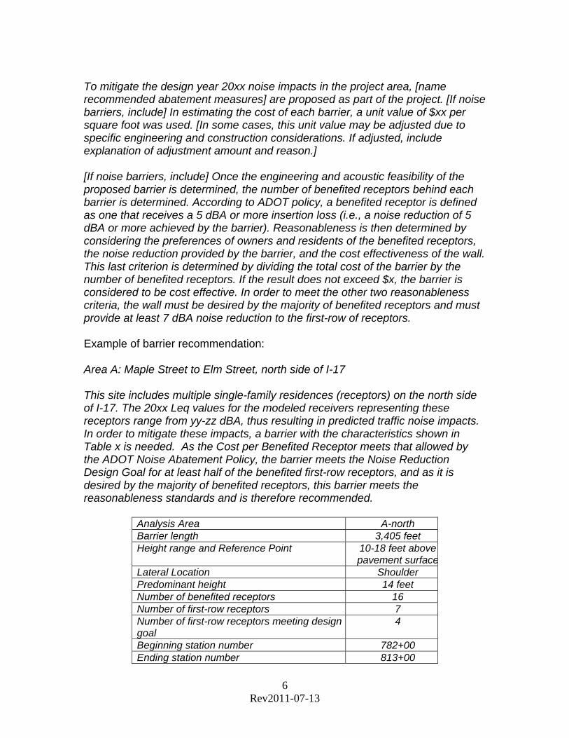
6 Rev2011-07-13
To mitigate the design year 20xx noise impacts in the project area, [name recommended abatement measures] are proposed as part of the project. [If noise barriers, include] In estimating the cost of each barrier, a unit value of $xx per square foot was used. [In some cases, this unit value may be adjusted due to specific engineering and construction considerations. If adjusted, include explanation of adjustment amount and reason.] [If noise barriers, include] Once the engineering and acoustic feasibility of the proposed barrier is determined, the number of benefited receptors behind each barrier is determined. According to ADOT policy, a benefited receptor is defined as one that receives a 5 dBA or more insertion loss (i.e., a noise reduction of 5 dBA or more achieved by the barrier). Reasonableness is then determined by considering the preferences of owners and residents of the benefited receptors, the noise reduction provided by the barrier, and the cost effectiveness of the wall. This last criterion is determined by dividing the total cost of the barrier by the number of benefited receptors. If the result does not exceed $x, the barrier is considered to be cost effective. In order to meet the other two reasonableness criteria, the wall must be desired by the majority of benefited receptors and must provide at least 7 dBA noise reduction to the first-row of receptors. Example of barrier recommendation: Area A: Maple Street to Elm Street, north side of I-17 This site includes multiple single-family residences (receptors) on the north side of I-17. The 20xx Leq values for the modeled receivers representing these receptors range from yy-zz dBA, thus resulting in predicted traffic noise impacts. In order to mitigate these impacts, a barrier with the characteristics shown in Table x is needed. As the Cost per Benefited Receptor meets that allowed by the ADOT Noise Abatement Policy, the barrier meets the Noise Reduction Design Goal for at least half of the benefited first-row receptors, and as it is desired by the majority of benefited receptors, this barrier meets the reasonableness standards and is therefore recommended.
Analysis Area A-north Barrier length 3,405 feet Height range and Reference Point 10-18 feet above
pavement surfaceLateral Location Shoulder Predominant height 14 feet Number of benefited receptors 16 Number of first-row receptors 7 Number of first-row receptors meeting design goal
4
Beginning station number 782+00 Ending station number 813+00
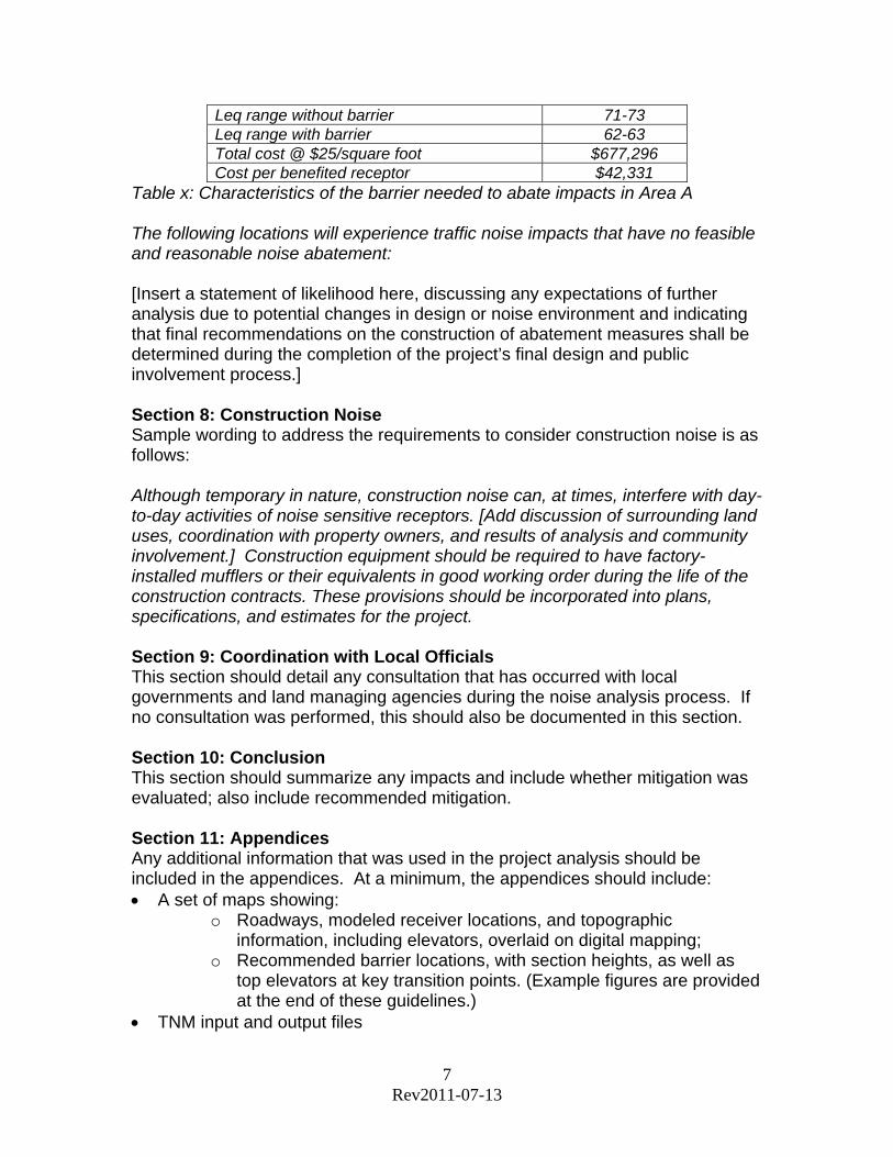
7 Rev2011-07-13
Leq range without barrier 71-73 Leq range with barrier 62-63 Total cost @ $25/square foot $677,296 Cost per benefited receptor $42,331
Table x: Characteristics of the barrier needed to abate impacts in Area A The following locations will experience traffic noise impacts that have no feasible and reasonable noise abatement: [Insert a statement of likelihood here, discussing any expectations of further analysis due to potential changes in design or noise environment and indicating that final recommendations on the construction of abatement measures shall be determined during the completion of the project’s final design and public involvement process.] Section 8: Construction Noise Sample wording to address the requirements to consider construction noise is as follows: Although temporary in nature, construction noise can, at times, interfere with day-to-day activities of noise sensitive receptors. [Add discussion of surrounding land uses, coordination with property owners, and results of analysis and community involvement.] Construction equipment should be required to have factory-installed mufflers or their equivalents in good working order during the life of the construction contracts. These provisions should be incorporated into plans, specifications, and estimates for the project. Section 9: Coordination with Local Officials This section should detail any consultation that has occurred with local governments and land managing agencies during the noise analysis process. If no consultation was performed, this should also be documented in this section. Section 10: Conclusion This section should summarize any impacts and include whether mitigation was evaluated; also include recommended mitigation. Section 11: Appendices Any additional information that was used in the project analysis should be included in the appendices. At a minimum, the appendices should include: A set of maps showing:
o Roadways, modeled receiver locations, and topographic information, including elevators, overlaid on digital mapping;
o Recommended barrier locations, with section heights, as well as top elevators at key transition points. (Example figures are provided at the end of these guidelines.)
TNM input and output files