fall 2015 afshin hemmatyar sharif university of technology wireless communication introduction
TRANSCRIPT
Fall 2015Fall 2015
Afshin HemmatyarAfshin Hemmatyar
Sharif University of Technology
Wireless CommunicationWireless Communication
IntroductionIntroduction

ReferencesReferences
A. Goldsmith, Wireless Communications, Cambridge University Press, 2005. D. Tse and D. Vaswanth, Fundamentals of Wireless Communications, Cambridge University Press, 2005. T. Rappaport, Wireless Communications, Principles and Practice, 2nd Edition, Prentice Hall. J. Fayyaz, Radio Design of Cellular Networks, Naghoos Press, 2011.
22

ContentsContents
Background and PreviewBackground and Preview Wireless Propagation ChannelWireless Propagation Channel Multiple Access MethodsMultiple Access Methods Cellular SystemsCellular Systems Diversity IssuesDiversity Issues Information Transmission CapacityInformation Transmission Capacity Multiple Antenna TechnologiesMultiple Antenna Technologies Cooperative Communications Cooperative Communications
33

Wired Vs. Wireless CommunicationsWired Vs. Wireless Communications
WiredWirelessEach cable is a different channel One media (cable) shared by all
Signal attenuation is low High signal attenuation
No interference High interference
noise; co-channel interference; adjacent channel interference
44

AdvantagesAdvantages• Sometimes it is impractical to lay cablesSometimes it is impractical to lay cables• User mobilityUser mobility• Cost Cost
LimitationsLimitations• BandwidthBandwidth• FidelityFidelity• PowerPower• SecuritySecurity
Why Wireless?Why Wireless?
55

Wireless ≈ WavesWireless ≈ Waves
Electromagnetic radiationElectromagnetic radiation Emitted by sinusoidal current running Emitted by sinusoidal current running
through a wire (transmitting antenna)through a wire (transmitting antenna) Creates propagating sinusoidal magnetic Creates propagating sinusoidal magnetic
and electric fields according to Maxwell’s and electric fields according to Maxwell’s equations:equations:
Fields induce current in receiving antenna. Fields induce current in receiving antenna. 66

Propagation PrinciplePropagation Principle
electricfield
magneticfield
propagation direction
77

Propagation MechanismsPropagation Mechanisms
Non Line-of-Sight
Reflection
λ << D
Diffraction
λ D
Scattering
λ >> D
S D
Line-of-Sight
88

Propagation in the “Real World”Propagation in the “Real World”
a wave can be absorbed
reflectreflect
penetratepenetrate
bend
99

The Cluttered World of Radio WavesThe Cluttered World of Radio Waves
walls
hallwayswindows
trees
vehicles
rain
hills
girders
1010

Electromagnetic SpectrumElectromagnetic Spectrum
Propagation characteristics are different in each frequency band.
UV
1 MHz1 kHz 1 GHz 1 THz 1 PHz 1 EHz
infrared visible
X raysGamma rays
LF HF VHF UHF SHF EHFMF
AM ra
dio
S/W ra
dio
FM ra
dio
TV TV cellu
lar
902 – 928 Mhz
2.4 – 2.4835 Ghz
5.725 – 5.785 Ghz
ISM band
30kHz 300kHz 3MHz 30MHz 300MHz 30GHz 300GHz
10km 1km 100m 10m 1m 10cm 1cm 1mm
3GHz
1111

Evaluating FrequenciesEvaluating Frequencies
50 MHz-250 MHz50 MHz-250 MHz: Good for outdoor range, large : Good for outdoor range, large antenna size, bending and penetrating. No foliage antenna size, bending and penetrating. No foliage problems. “Sees” metallic building structures, problems. “Sees” metallic building structures, doesn’t pass through windows or down corridors. doesn’t pass through windows or down corridors.
450 MHz to 2 GHz450 MHz to 2 GHz: - Good compromise for cellular-: - Good compromise for cellular-type systems. Small antenna, but big enough for type systems. Small antenna, but big enough for outdoor range. Minor foliage effects. OK for windows outdoor range. Minor foliage effects. OK for windows walls and corridors.walls and corridors.
5-20 GHz5-20 GHz: Antenna too small for outdoor range. : Antenna too small for outdoor range. Foliage and rain effects. Indoor microcells, Point-to-Foliage and rain effects. Indoor microcells, Point-to-point, and Satellites to ground stations.point, and Satellites to ground stations.
1212

Unlicensed Radio SpectrumUnlicensed Radio Spectrum(ISM: Industrial, Science, Medicine)(ISM: Industrial, Science, Medicine)
902 Mhz
928 Mhz
26 Mhz 83.5 Mhz 125 Mhz
2.4 Ghz
2.4835 Ghz5.725 Ghz
5.850 Ghz
cordless phonesbaby monitorsWaveLan
802.11bBluetoothMicrowave oven
802.11a
33cm 12cm 5cm
1313

Free-space Path-loss Free-space Path-loss
Power of wireless transmission reduces with Power of wireless transmission reduces with square of distance (due to surface area square of distance (due to surface area increase of sphere).increase of sphere).
Reduction also depends on wavelength:Reduction also depends on wavelength:• Long wave length (low frequency) has less lossLong wave length (low frequency) has less loss• Short wave length (high frequency) has more lossShort wave length (high frequency) has more loss
24
..
d
LP
1414

Path-loss ModelsPath-loss Models
Path-Loss Exponent Depends on environment:Path-Loss Exponent Depends on environment:
L(d) = L(dL(d) = L(d00)(d/d)(d/d00))nn
Free spaceFree space n = 2n = 2
Urban area cellularUrban area cellular n = 2.7 to 3.5n = 2.7 to 3.5
Shadowed urban cellShadowed urban cell n = 3 to 5n = 3 to 5
In building LOSIn building LOS n = 1.6 to 1.8n = 1.6 to 1.8
Obstructed in buildingObstructed in building n = 4 to 6n = 4 to 6
Obstructed in factoriesObstructed in factories n = 2 to 3n = 2 to 3
1515

Multi-path PropagationMulti-path Propagation
Electromagnetic waves bounce off of Electromagnetic waves bounce off of conductive (metal) objects.conductive (metal) objects.
Reflected waves received along with Reflected waves received along with direct wave.direct wave.
1616

Multi-Path EffectMulti-Path Effect
Multi-path components are delayed Multi-path components are delayed depending on path length, causes depending on path length, causes delay spreaddelay spread..
Phase shift Phase shift causes frequency causes frequency dependent constructive / destructive dependent constructive / destructive interference.interference.
1717

Multi-transmitter InterferenceMulti-transmitter Interference
Similar to multi-pathSimilar to multi-path
Two transmitting stations will Two transmitting stations will constructively/destructively interfere constructively/destructively interfere with each other at the receiver.with each other at the receiver.
Receiver will “hear” the sum of the Receiver will “hear” the sum of the two signals, which usually means two signals, which usually means garbage.garbage.
1818

ModulationModulation Modulation allows the wave to carry Modulation allows the wave to carry
information by adjusting its properties information by adjusting its properties ((AmplitudeAmplitude, , FrequencyFrequency, , and Phaseand Phase) in a ) in a time varying way.time varying way.
Digital modulation using discrete “steps” Digital modulation using discrete “steps” so that information can be recovered well so that information can be recovered well despite noise/interference.despite noise/interference.• 8VSB - US HDTV8VSB - US HDTV• BFSK - Mote Sensor NetworksBFSK - Mote Sensor Networks• QPSK - 2 Mbps 802.11 & CMDA(IS-95)QPSK - 2 Mbps 802.11 & CMDA(IS-95)
1919

Symbol Rate & BandwidthSymbol Rate & Bandwidth Modulation allows transmission of one of Modulation allows transmission of one of
several possible symbols (two or more).several possible symbols (two or more).
Data stream is encoded by transmitting Data stream is encoded by transmitting several symbols in succession.several symbols in succession.
Symbol rate ≈ BandwidthSymbol rate ≈ Bandwidth• Symbol Rate or Baud Rate (symbols/sec)Symbol Rate or Baud Rate (symbols/sec)• Bit Rate or Throughput (bits/sec)Bit Rate or Throughput (bits/sec)• Spectrum Usage or Bandwidth (Hz)Spectrum Usage or Bandwidth (Hz)
Inter-symbol interference (ISI) occurs unless Inter-symbol interference (ISI) occurs unless delay spread << symbol time.delay spread << symbol time.
2020
Thermal NoiseThermal Noise
Ever-present thermal noise in wireless Ever-present thermal noise in wireless medium.medium.
Sums with any wireless transmission.Sums with any wireless transmission.
Potentially causes errors in reception Potentially causes errors in reception (digital) or degradation of quality (analog).(digital) or degradation of quality (analog).
Effectively limits transmission range whenEffectively limits transmission range when
transmitting signal strength falls below a transmitting signal strength falls below a threshold.threshold.
2121
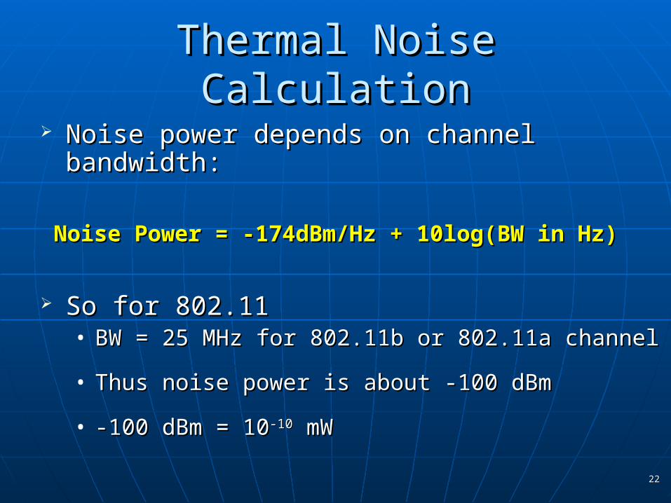
Thermal Noise CalculationThermal Noise Calculation
Noise power depends on channel bandwidth:Noise power depends on channel bandwidth:
Noise Power = -174dBm/Hz + 10log(BW in Hz)Noise Power = -174dBm/Hz + 10log(BW in Hz)
So for 802.11So for 802.11• BW = 25 MHz for 802.11b or 802.11a channelBW = 25 MHz for 802.11b or 802.11a channel
• Thus noise power is about -100 dBmThus noise power is about -100 dBm
• -100 dBm = 10-100 dBm = 10-10-10 mW mW
2222

Physical Channel Properties ReviewPhysical Channel Properties Review Received signal power Received signal power depends on:depends on:
• Transmit powerTransmit power• Loss over distance (falls off by dLoss over distance (falls off by dnn))• Shadowing (e.g. absorption by walls)Shadowing (e.g. absorption by walls)• Multi-path (e.g. bouncing off of metal objects)Multi-path (e.g. bouncing off of metal objects)
Noise power Noise power depends on:depends on:• Thermal noise Thermal noise • Environmental noise (e.g. microwave ovens)Environmental noise (e.g. microwave ovens)
Channel QualityChannel Quality• Related to Related to Signal to Noise RatioSignal to Noise Ratio
2323

Current Wireless TechnologiesCurrent Wireless Technologies
Cellular Telephony (GSM, CDMA2000)
Fixed Wireless Access (WiMax) Wireless Local Area Networks
Local Networks (Bluetooth, UWB)
Satellite Communications
2424

Cellular Telephony (1)Cellular Telephony (1)
2525

Cellular Telephony (2)Cellular Telephony (2)
2626

Cellular Telephony (3)Cellular Telephony (3)
Data is bursty, whereas voice is continuous.
3G widens the data pipeo 384Kbps to few Mbpso Standard based of WCDMAo Packet-based switching for both voice and data
New generationso HSDPA, HSPA+, LTEo WiMAx added to 3G
4G systems start to come upo Mostly based on OFDM
2727

Fixed Wireless Networks (WiMax)Fixed Wireless Networks (WiMax)
Provide broadband wireless access to homes/offices in a few Km range.
A potential replacement of ADSL
Provide high speed Internet and VOD
2828

Wireless Local Area Networks (1)Wireless Local Area Networks (1)
WLANs connect local computers (100m to a few Km range)
Breaks data into packets
Channel is shared (random access)
Backbone internet provides best-effort service
Poor performance in some applications (e.g. video)2929
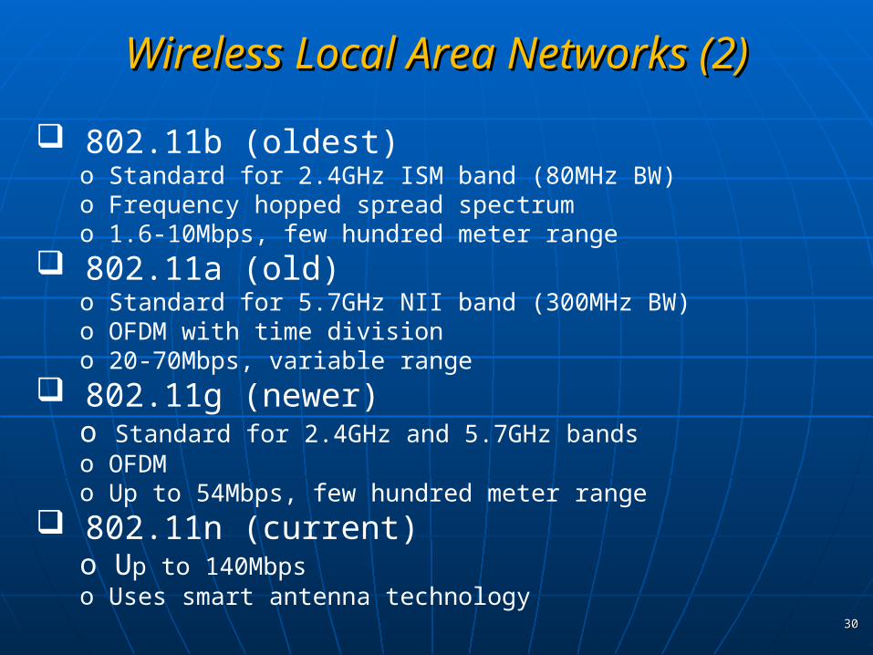
802.11b (oldest)o Standard for 2.4GHz ISM band (80MHz BW)o Frequency hopped spread spectrumo 1.6-10Mbps, few hundred meter range
802.11a (old)o Standard for 5.7GHz NII band (300MHz BW)o OFDM with time division o 20-70Mbps, variable range
802.11g (newer)o Standard for 2.4GHz and 5.7GHz bandso OFDMo Up to 54Mbps, few hundred meter range
802.11n (current)o Up to 140Mbpso Uses smart antenna technology
Wireless Local Area Networks (2)Wireless Local Area Networks (2)
3030

Ultra Wide-BandUltra Wide-Band
Also known as “Impulse Radio”.
Use very high bandwidth to decrease power level.
Hard synchronization
No license problem, but seems to interfere with GPS
Now mainly targeted to small distance applications. (home networks to replace Bluetooth)
Smaller delay and longer range than Bluetooth
Emerging as competitor for 802.11
3131

Satellite CommunicationsSatellite Communications
Cover very large areas.
Different orbit heightso GEO (36000 Km), MEO and LEO (<2000 Km)
Optimized for one-way transmissiono Radio (DAB) and TV (DVB-S) broadcast
Two-way systemso Expensive alternative to terrestrial systems
3232

Evolution of Current TechnologiesEvolution of Current Technologies
Link: Modulation, Coding, Adaptivity, Smart Antennas
Network: Dynamic resource allocation, Mobility support
Hardware: Better batteries, Circuits/Processors
Applications: Soft and adaptive QoS (main issue in real-time multi-media services)
3333

Moving toward Real MultimediaMoving toward Real Multimedia
VoiceDataVideo
Delay< 100 mSec-< 100 mSec
Packet loss< 1%0<1%
BER10-310-610-6
Data Rate8-32Kbps1-100 Mbps1-20 Mbps
TrafficContinuousBurstyContinuous
3434

Design ChallengesDesign Challenges
Wireless channels are capacity-limited broadcast communication medium.
o Two main problems in wireless media: Fading Interference
Traffic patterns, user locations, and network conditions are constantly changing.
Energy and delay constraints change design principles across all layers of the protocol stack.
3535
Emerging SystemsEmerging Systems
Ad-hoc Wireless Networks
Wireless Sensor Networks
Distributed Control Networks
Cooperative Networks
Cognitive Radio Networks
3636

Ad-hoc Wireless Networks (1)Ad-hoc Wireless Networks (1)
3737

Ad-hoc Wireless Networks (2)Ad-hoc Wireless Networks (2)
Peer-to-peer communications No backbone infrastructure Multi-hop routing Dynamic topology Fully connected with different link SNRs
3838

Ad-hoc Wireless Networks (3)Ad-hoc Wireless Networks (3)
Ad-hoc Wireless Networks provide a flexible network infrastructure for any emerging application.
The capacity of such a network is generally unknown.
Transmission, access, and routing strategies are generally ad-hoc
Energy constraints impose interesting design tradeoffs for communication and networking.
3939

Wireless Sensor Networks (1)Wireless Sensor Networks (1)
40404040

Wireless Sensor Networks (2)Wireless Sensor Networks (2)
Energy is the driving constraint. Nodes powered by non-rechargeable batteries. Data flows to central location. Low per-node rates but up to 100000 nodes. Data highly correlated in transmission. Nodes can cooperate in transmission, reception, compression, and signal processing. 4141

Wireless Sensor Networks (3)Wireless Sensor Networks (3)
(Energy-constrained nodes) Short-range networks must consider transmit, circuit, and processing energy.
o Sleep modes save energy but complicate networking.
Changes everything about the network design:
o Optimization of bit allocation across all protocolso Delay vs. throughput vs. node/network lifetime tradeoffso Optimization of nodes cooperationo Efficient MAC layer communication and Scheduling
4242

Distributed Control (1)Distributed Control (1)
Packet loss and/or delay impacts controller performance. Controller design should be robust to network faults. Joint application and communication network delay. Interesting ideas in packet-based communication and file transfer.
4343

There is no methodology to incorporate random delays or packet losses into control system design. The best rate/delay tradeoff for a communication system in distributed control can not be determined. Current autonomous vehicle platoon controllers are not string stable with any communication delay. What are the best routing technologies?
Distributed Control (2)Distributed Control (2)
4444
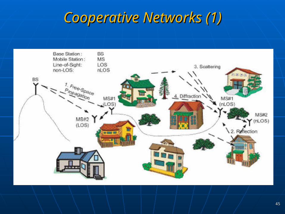
Cooperative Networks (1)Cooperative Networks (1)
4545

Increase coverage area Reduce number of “blind spots” Reduce transmit power per node
Increase in transceiver complexity
More complex synchronization problems More interference to be handled properly Higher end-to-end delays Additional delay to be handled in real-time applications
Cooperative Networks (2)Cooperative Networks (2)
4646

Cognitive Radio (1)Cognitive Radio (1)
Available spectrum looks scarce.
Measurements show the allocated spectrum is vastly underutilized.
4747

Cognitive Radio (2)Cognitive Radio (2)
4848

Cognitive Radio (3)Cognitive Radio (3) Sense, learn, and exploit the environment One “simple” option:
o Use “un-used” spectrumo Agile Radioso Give priority to ”primary” users
But not receiving a signal in wireless environment does not mean that no signal is actually transmitted at that frequency! Even in simplest form is very challenging. Many ideas such as:
o Game Theoryo Near-Noise Level Signal detectiono BW transactionso Trust theories (how to identify users with “bad” intensions?)
4949
SummarySummary
The wireless vision encompasses many exciting systems and applications.
Technical challenges go across all layers of the system design.
Wireless systems today still have limited performance and interoperability.
5050