fds interfaceit sys series interface board · fds interfaceit sys series interface board developed...
TRANSCRIPT

FDS interfaceIT SYS Series Interface Board
Developed by TEKWorx
User Guide
Issue: 5 May, 2010

2
Introduction The package includes the SYS Series interface board, a USB cable, a power supply, and pre-wired connectors to interface your LED’s and switches to the interface board. There are four different SYS boards designed to manage specific areas of your flight deck.
FDS-SYS SERIES OF INPUT/OUTPUT INTERFACE BOARDS
FDS-
SXS1X FDS-
SXS2X FDS-
SXS3X FDS-
SXS4X
INPUTS 128 128 32 64
OUTPUTS 256 64 128 The SYS1X board is best suited for wiring the overhead panel, with 128 inputs for switches, while 256 outputs for LED’s are made available. The SYS2X board provides 128 additional inputs and can be used to augment either the overhead or the MIP/Pedestal areas of your project. The SYS3X board, with 32 inputs and 64 outputs was designed with the MIP/Pedestal in mind, while the SYS4X board can be regarded as a SYS3X board on steroids with double the number of inputs/outputs enabled by the SYS3X board. All three boards are Plug & Play. It is also important to notice the following: Caution: Components on this board are susceptible to damage by electrostatic discharge (ESD). Ensure that you are properly grounded before handing this board. This document is organized into the following sections.
· Installation of the interfaceIT software and connection of the board to your computer
· System and board architecture · Wiring of the board inputs and outputs to your flight deck switches and LED’s and
using the I/O automatic identification feature · Use of the Configuration File download feature to activate functions
There are several unique features associated with the SYS Series of boards. These include the capability to download pre-configured functions to activate features, the ability to identify which port is assigned to which function (switch or LED), negating the need to maintain a paper record of what is connected to what, and the ability to connect
3
the SYS board to any computer that communicates via WideFS, increasing the operating flexibility of the system.
Installation of the interfaceIT Software For installing the software; all you need to do is download the latest version of the software and double click on the unzipped executable file. The program is available at: http://www.tekworx.ca/downloads.html
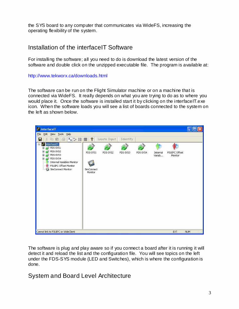
The software can be run on the Flight Simulator machine or on a machine that is connected via WideFS. It really depends on what you are trying to do as to where you would place it. Once the software is installed start it by clicking on the interfaceIT.exe icon. When the software loads you will see a list of boards connected to the system on the left as shown below.
The software is plug and play aware so if you connect a board after it is running it will detect it and reload the list and the configuration file. You will see topics on the left under the FDS-SYS module (LED and Switches), which is where the configuration is done.
System and Board Level Architecture

4
The following diagram shows how the SYS series boards interface at a system level.
As shown, your flight deck switches, push buttons, rotary selectors and LED’s are represented by the top box. These inputs and outputs are wired to the interfaceIT SYS cards. The SYS cards are then programmed, using FSUIPC functions, or offsets (assigned by FSUIPC) to Project Magenta, which then communicate with Flight Simulator. interfaceIT also has the capability to perform specialized functions defined by Internal Variables as well. The SYS board architecture: For illustrative purposes, the FDS-SYS3 Board is used in the following example. On the upper left side of the board in the red box are the connectors for the outputs, used to illuminate LED’s used in K2 or EM1 switches and annunciators. The SYS3 board shown in the above example has 8 connectors, arranged in a 2-wide by 4-deep configuration. On the upper right hand side of the board in the green box are shown the 32 inputs. In this case we have 4 connectors aligned along the top. In the lower right hand side is the USB connector.

5
One very important note, to manage the power effectively across the board, each connector has 8 active leads and a common return lead (ground). When you wire your inputs and outputs you have to utilize the common ground with each of the 8 active leads. If you wire your system and a switch/LED doesn’t work, the first place to check for trouble will be to make sure you followed the rule above. More details on wiring configurations are shown in the section “Programming and Configuring a Switch” later in the document.
Wiring the SYS board and using the Locate I/O Mode Wiring the SYS board is very straightforward. Just remember to follow the rule provided above and make sure that you maintain continuity between your active leads and the common return ground. Also, make sure that you wire your LED’s to the Outputs and your switches to the Inputs. Locate Input Mode The Locate Input Mode of the software will allow you to easily locate any input that you have wired. The advantage of this feature is so that you can wire you simulator without having to remember which switch is on what input. Once this mode is activated when you toggle / push / change a switch it will automatically select that switch in the graphical interface as well as perform the currently programmed action. Launch the interfaceIT controller software.

6
Right mouse click the board you want to identify the inputs and click the Locate Input Mode menu item.
When activated the Locate Input button on the toolbar will become active.

7
Once activated the software will automatically locate any switch that you push / toggle / change allowing for easy configuration.
To turn off the Locate Input Mode, simply click the Locate Input button on the toolbar, or right click the panel item and select Locate Input Mode This is a good time to discuss the Description and Options section as shown on the above screen. When no function has yet been assigned, both areas are blank. When a function has been assigned, the description and/or requirements for the function to be used is identified. For example, it might state that pmSystems is required for proper operation. The switch has an option whereby if the box is checked a momentary switch can be “latched” or toggled on/off using the interfaceIT software. The output options different and will be discussed later. Locate Output Mode Likewise, to validate that the wired LED connection, as well as verifying the function that needs to be assigned on the board to that LED you can use the Locate Output Mode feature. If you then click on the provisioned LED and select the Identify output category, the LED will flash, letting you make sure that you provisioned the correct item.

8
In addition, the grayed out Identify icon on the top of the screen will turn active.
Clicking on the highlighted icon will extinguish the LED and you can then move to the next item. For the Options when using outputs you can see that the output can be inverted, the LED can be on, flash slow, or flash fast.
Downloading Configuration Files to Activate Specific Functions

9
A very innovative feature of the interfaceIT SYS series of cards is the ability to download predefined Configuration Files (using a XML file format) that eliminate all of the offset assignments and options associated with the general use of FSUIPC. To download a preconfigured file, click on the Tools menu at the top of the screen.
This opens three options, Check for Software Updates, Check for Hardware Updates, and Download Import Files. Click on the latter and the following screen is provided.
The Download Configuration Files screen has several sub-folders. The type of aircraft is listed across the top (B737NG, B747, B744, B777 in the above example). In addition, there is a tab for Support Files. (More on this later) Along the left hand side are the sub-folder tabs for Inputs and Outputs. The case above has the B737NG

10
active, as well as the Inputs sub-folder. If we then click on the List Files icon, the following screen opens with all of the provided configurations files for the B737NG inputs (toggle switches, pushbuttons and rotary selector switches) and a list of the available preconfigured fi les are displayed.
As shown below, when you highlight a configuration and right mouse click, a sub-window opens that asks if you want to select all files, download the fi le highlighted, or view the description for the highlighted file.

11
If you select the View Description selection, the following window opens that lets you review the specifics of the selected configuration.
Select which file you want to download (in this example we select the first entry – B737NG Autobrake (1)) and click on the Download icon. A message at the bottom of the screen shows that the selected file was retrieved. It is placed in the folder that you specified as the Download Path. In the example this was: C:\interfaceIT\B747 Files Close the connection when you have downloaded the applicable files for your application. The nomenclature used for the files is as follows: Aircraft Type-Input/Output-Function So, for the example selected above we have B737NG-I-Autobrake (1).xml In this manner it is possible to download and import into your SYS boards all of the functions necessary to make your flight deck operational. Once you’ve downloaded the applicable files, importing them into the SYS cards is easily accomplished as follows. First right-click on the switch to bring up the function menu and select the Import configuration-overwrite name.

12
This will result in a screen opening where you have identified the location of your xml configuration files.
Select the file that we downloaded from the server and click on Open

13
The switch port number 30 has now been provisioned with the configuration file for the Autobrake (4) function. A description of the function is provided in the box to the right. In this case it identifies the switch as being a rotary selector switch for the B747-400 Pedestal It also lists any special issues related to using this function (in this case, FSUIPC must be available) and lists the version number of the configuration. The suggested process to provision your simulator using the above technique is:
1. Wire the inputs and outputs from your switches and LED’s to the SYS boards 2. Use the identity input and output functions to make sure that you have connectivity,
and that the correct switch/LED is operational 3. Download the desired configuration file and import it into your SYS board
It is also possible to take the completed interfaceIT.xml file, place that in the proper folder, and have all inputs and outputs immediately active for the particular simulator you have constructed. However, you must have wired your simulator identically to the .xml files being used, tricky business at best, but possible.
Download Support Files The download support files consist of functions that transcend one particular aircraft type (B737 or B747) or system logic useful for better utilizing the SYS cards. Readme files are included to better direct the user in determining what, if any, of these files are of use in their particular situation. For example, current support fi les include systems logic for Project Magenta’s pmSystems that enhances the B747. Other files include a collection of offsets for the pedestal that transcend a particular aircraft type.

14
Configuring and Programming a Switch Following are the schematic drawings associated with the wiring of the various switch types used: rotary selector, toggle, 2-position toggle, and pushbutton.
Rotary Selector
Toggle Switch
Toggle Switch – 2 Position
Push Button Switch
It is important when wiring your switches and LED’s to use the common ground lead on each wiring assembly with each of the eight leads for that assembly as discussed earlier. If there are configurations that are not yet available for download from the server, or you just wish to configure your functions yourself, the following provides an example of how to perform these functions using the interfaceIT provisioning software. We are going to pick one of the light switches to activate. Select a toggle switch (or locate an already connected one) and then right click the switch item. From here you will be able to add a number of actions that will execute in order. We are going to select “Add input action / Update FSUIPC / On”.

15
Once that is added you will be taken to a configuration screen for the action you have just added.

16
Here you want to click the icon next to description to bring up the FSUIPC browser window. In the browser window you will want to select “Flight Simulator” as the source to populate the offset list. In the search field (currently it is a left to right search and in the next build it will be a straight text search). In the search field type “lights” and it wi ll select the “Lights (FS2k/CFS2)” item.
If you scroll to the right you will see Peter Dowson’s notes on which bit value is for each switch.

17
Bits are one of the hardest to understand (that is why I picked it). We are going to do Panel lights so we note that it is value 32 which is bit 5 (Bit 0 = 1, Bit 1 = 2, Bit 2 = 4, Bit 3 = 8…..). We click the “Select” button to select this offset and will be returned to the configuration screen. All the information you need other than the bit is set for you. We just need to go and add 5 to the bit field.
At this point we have now configured a switch to turn on the panel lights and it will be active immediately and ready for testing. If you toggle you switch (and Flight Simulator is running) you should see the panel lights go on. To configure them to be turned off, you just need to repeat the process; select the same switch, right click and add a action, “Add input action / Update FSUIPC / Off”, pick the offset, however now we want to “clear bit” for the operation and select bit 5.
18
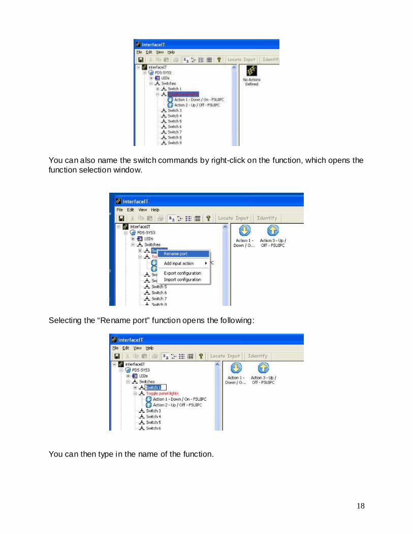
You can also name the switch commands by right-click on the function, which opens the function selection window.
Selecting the “Rename port” function opens the following:
You can then type in the name of the function.

19
LED Configuration and Operation To program an LED to turn on or off, first of all refer to the schematic diagram to make sure you have the anode and cathode selected correctly. For additional clarification, the anode is mechanically identified by having a longer lead as shown in the following photograph.
When wiring LED’s each 8 LED’s have a common cathode (negative) line which goes to the black wire in the bundle. The 8 other red lines are the anode (positive) connections for the LED’s. As mentioned earlier in the switch configuration section it is important to only connect the cathodes for that connector to the black line in that connector. Each of the connectors has it own common that gets connected to each of the eight switches. The following drawing shows the correct connections for the LED’s

20
LED Connections
There are cases where two LED’s are required for a function, for example, for the annunciators. In these cases, two LED’s may be connected in parallel using a single output of the SYS3 board. The screens to enable LED functions are similar to that used for the switches, including the ability to add multiple actions for activating the LED. Right clicking on a LED opens the following:

21
This brings up the FSUIPC chooser, except you only have to choose outputs. For this example we selected the Pause flag from Flight Simulator. Again, to select the options in the “Action” window you need to look at Pete Dowson’s notes to determine which action to select.
When you select a function, the Data Type is automatically provisioned and you don’t have to worry about bits, bytes, words, or double-words. And since the SYS boards are designed for switch inputs and LED outputs. The functions selected are most often one of the two options:
1. Setting a bit and clearing a bit (toggling a switch on or off), or 2. Setting a value, in the case of a rotary selector switch
Advanced Programming Capabilities The xml file is really a macro, capable of performing multiple functions. A case in point is defining a series of key strokes to activate a function in Flight Simulator.

22
In this case, we are going to program the series CTRL + NumPad 0 to activate the rudder trim to the left command using FSUIPC to send a command directly to Flight Simulator.
As shown above, we select the Add input function, the using the menu, select “Send Keystroke to Flight Simulator via FSUIPC” with the On function selected.

23
When you click on the icon to the right of the Keystroke box, the Recording screen opens. The series of keystrokes desired is entered, then the Save button is pressed. The is then named, saved in a XML-like format, and wired to a switch to control the function. That’s all there is to it. To control a function using a keystroke to a Project Magenta window is also possible, but a bit trickier.

24
As shown above, the same process is followed, except the Send Keystroke to a Project Magenta Window is selected.
The same Recording window opens when the icon is clicked and the keystroke is recorded. In this case, we are using the single letter “T” to toggle the Heading Select from Magnetic to True North heading. Since this command is specific to the Project Magenta PFD program, after the keystroke is saved, and the icon to the right of the Window Information is clicked, the following Find Window screen is opened. When you drag the icon up to the Project Magenta Glass Cockpit window, the information shown below is recorded.

25
Finally, as shown above, the information is saved to the xml file HeadingSel to be provisioned to a toggle switch on the Main Instrument Panel. When toggled, the PFD and ND heading information changes to reflect True North versus Magnetic North on the display.
Another feature introduced with Version interfaceIT_MCS_v2.3.121is the ability to define a keystroke to change the focus between several different programs. For example, you might want to have Squackbox and ServInfo on the same computer and toggle between the two programs without having to use a mouse to effect the change.

26
By using the Sending Keystroke to a Window (Changing Focus) option under Add Input Function, you get the following screen:
Use the process outlined previously to incorporate the window information and check the Leave focus on target window box checked. In addition to supporting a number of keystrokes to define a function, interfaceIT supports enabling multiple functions in one xml file. A good example is a well known weather radar program that replicates the functions of the Rockwell/Collins WXR2100 system used in most commercial jets. Provisioning the rotary selector switch to turn the radar on and/or select wxr/turb mode is straightforward, with a single offset assigned to the position. However, to adjust the antenna tilt angle a second function needs to be provisioned to tilt the antenna up or down. To complete both functions with a single selector switch is easy to accomplish with interfaceIT. First of all, using offset 6D01 assign values that reflect the tilt angle (in quarter degree steps). For example, a 3 degree up angle would be assigned a value of 12. A 6 degree angle, 24. A 9 degree angle, 36. The following example provisions a 3 degree angle.

27
Now that you have the angle defined, you need to assign a sign (+/-) to tilt the dish upward or down. Looking at the documentation, you need to assign a value of 17 to offset 6D00 to be positive, and a value of 18 to be negative. In this case we will tilt the antenna up (Value of 17)
And there you have it. A single position on the selector switch of a commonly used radar panel to replicate the function of the radar system as well as the tilt angle of the radar antenna.