form-ienvironmentclearance.nic.in/writereaddata/formb/ec/form...1 form-i for expansion for...
TRANSCRIPT
1
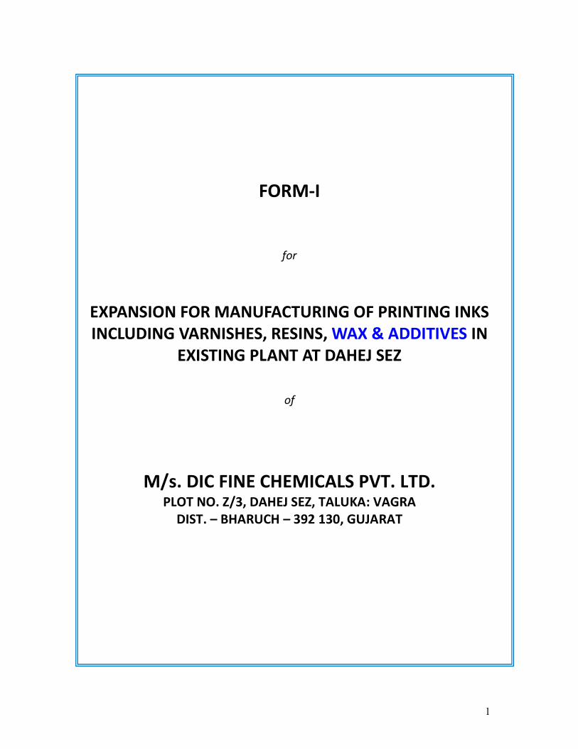
FORM-I
for
EXPANSION FOR MANUFACTURING OF PRINTING INKS
INCLUDING VARNISHES, RESINS, WAX & ADDITIVES IN
EXISTING PLANT AT DAHEJ SEZ
of
M/s. DIC FINE CHEMICALS PVT. LTD. PLOT NO. Z/3, DAHEJ SEZ, TALUKA: VAGRA
DIST. – BHARUCH – 392 130, GUJARAT
2
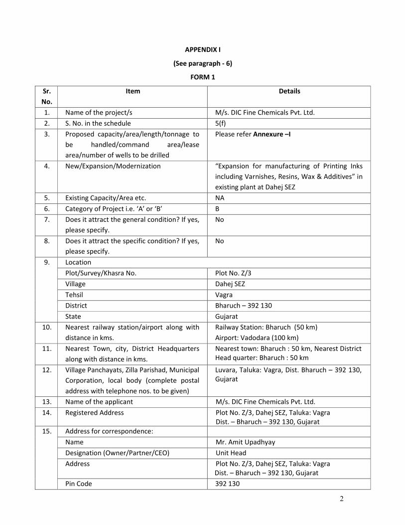
APPENDIX I
(See paragraph - 6)
FORM 1
Sr.
No.
Item Details
1. Name of the project/s M/s. DIC Fine Chemicals Pvt. Ltd.
2. S. No. in the schedule 5(f)
3. Proposed capacity/area/length/tonnage to
be handled/command area/lease
area/number of wells to be drilled
Please refer Annexure –I
4. New/Expansion/Modernization “Expansion for manufacturing of Printing Inks
including Varnishes, Resins, Wax & Additives” in
existing plant at Dahej SEZ
5. Existing Capacity/Area etc. NA
6. Category of Project i.e. ‘A’ or ‘B’ B
7. Does it attract the general condition? If yes,
please specify.
No
8. Does it attract the specific condition? If yes,
please specify.
No
Location
Plot/Survey/Khasra No. Plot No. Z/3
Village Dahej SEZ
Tehsil Vagra
District Bharuch – 392 130
9.
State Gujarat
10. Nearest railway station/airport along with
distance in kms.
Railway Station: Bharuch (50 km)
Airport: Vadodara (100 km)
11. Nearest Town, city, District Headquarters
along with distance in kms.
Nearest town: Bharuch : 50 km, Nearest District
Head quarter: Bharuch : 50 km
12. Village Panchayats, Zilla Parishad, Municipal
Corporation, local body (complete postal
address with telephone nos. to be given)
Luvara, Taluka: Vagra, Dist. Bharuch – 392 130,
Gujarat
13. Name of the applicant M/s. DIC Fine Chemicals Pvt. Ltd.
14. Registered Address Plot No. Z/3, Dahej SEZ, Taluka: Vagra
Dist. – Bharuch – 392 130, Gujarat
Address for correspondence:
Name Mr. Amit Upadhyay
Designation (Owner/Partner/CEO) Unit Head
Address Plot No. Z/3, Dahej SEZ, Taluka: Vagra
Dist. – Bharuch – 392 130, Gujarat
15.
Pin Code 392 130
3
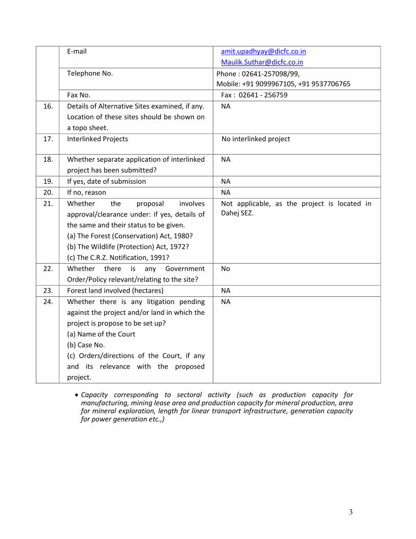
E-mail [email protected]
Telephone No. Phone : 02641-257098/99,
Mobile: +91 9099967105, +91 9537706765
Fax No. Fax : 02641 - 256759
16. Details of Alternative Sites examined, if any.
Location of these sites should be shown on
a topo sheet.
NA
17. Interlinked Projects No interlinked project
18. Whether separate application of interlinked
project has been submitted?
NA
19. If yes, date of submission NA
20. If no, reason NA
21. Whether the proposal involves
approval/clearance under: if yes, details of
the same and their status to be given.
(a) The Forest (Conservation) Act, 1980?
(b) The Wildlife (Protection) Act, 1972?
(c) The C.R.Z. Notification, 1991?
Not applicable, as the project is located in
Dahej SEZ.
22. Whether there is any Government
Order/Policy relevant/relating to the site?
No
23. Forest land involved (hectares) NA
24. Whether there is any litigation pending
against the project and/or land in which the
project is propose to be set up?
(a) Name of the Court
(b) Case No.
(c) Orders/directions of the Court, if any
and its relevance with the proposed
project.
NA
• Capacity corresponding to sectoral activity (such as production capacity for
manufacturing, mining lease area and production capacity for mineral production, area for mineral exploration, length for linear transport infrastructure, generation capacity for power generation etc.,)
4
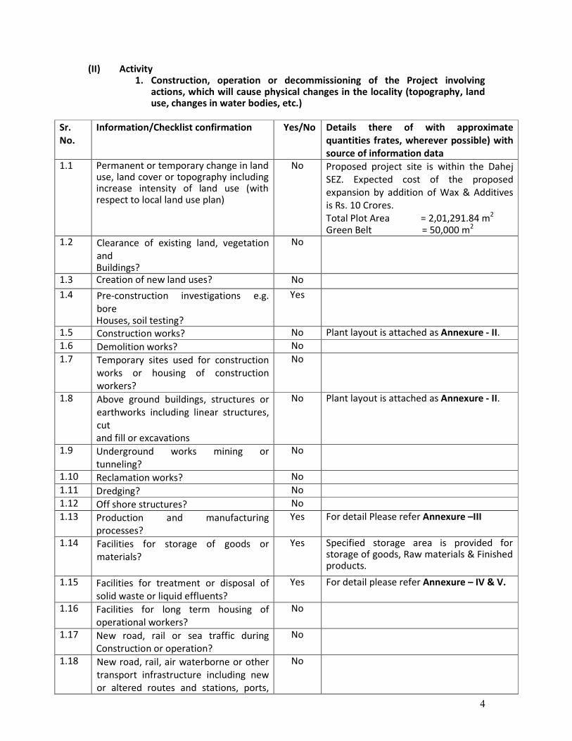
(II) Activity 1. Construction, operation or decommissioning of the Project involving
actions, which will cause physical changes in the locality (topography, land use, changes in water bodies, etc.)
Sr.
No.
Information/Checklist confirmation Yes/No Details there of with approximate
quantities frates, wherever possible) with
source of information data
1.1 Permanent or temporary change in land use, land cover or topography including increase intensity of land use (with respect to local land use plan)
No Proposed project site is within the Dahej
SEZ. Expected cost of the proposed
expansion by addition of Wax & Additives
is Rs. 10 Crores.
Total Plot Area = 2,01,291.84 m2
Green Belt = 50,000 m2 1.2 Clearance of existing land, vegetation
and Buildings?
No
1.3 Creation of new land uses? No
1.4 Pre-construction investigations e.g.
bore Houses, soil testing?
Yes
1.5 Construction works? No Plant layout is attached as Annexure - II.
1.6 Demolition works? No
1.7 Temporary sites used for construction
works or housing of construction
workers?
No
1.8 Above ground buildings, structures or
earthworks including linear structures,
cut
and fill or excavations
No Plant layout is attached as Annexure - II.
1.9 Underground works mining or
tunneling?
No
1.10 Reclamation works? No
1.11 Dredging? No
1.12 Off shore structures? No
1.13 Production and manufacturing
processes?
Yes For detail Please refer Annexure –III
1.14 Facilities for storage of goods or
materials?
Yes Specified storage area is provided for storage of goods, Raw materials & Finished products.
1.15 Facilities for treatment or disposal of
solid waste or liquid effluents?
Yes For detail please refer Annexure – IV & V.
1.16 Facilities for long term housing of
operational workers?
No
1.17 New road, rail or sea traffic during
Construction or operation?
No
1.18 New road, rail, air waterborne or other
transport infrastructure including new
or altered routes and stations, ports,
No
5
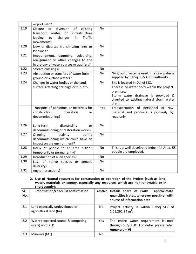
airports etc?
1.19 Closure or diversion of existing
transport routes or infrastructure
leading to changes in Traffic
movements?
No
1.20 New or diverted transmission lines or
Pipelines?
No
1.21 Impoundment, damming, culverting,
realignment or other changes to the
hydrology of watercourses or aquifers?
No
1.22 Stream crossings? No
1.23 Abstraction or transfers of water form
ground or surface waters?
No No ground water is used. The raw water is supplied by Dahej SEZ/ GIDC authority.
1.24 Changes in water bodies or the land
surface Affecting drainage or run-off?
No Site is located in Dahej SEZ.
There is no water body within the project
premises. Storm water drainage is provided & diverted to existing natural storm water drain.
Transport of personnel or materials for
construction, operation or
decommissioning?
Yes Transportation of personnel or raw
material and products is primarily by
road only.
1.26 Long-term dismantling or
decommissioning or restoration works?
No
1.27 Ongoing activity during
decommissioning which could have an
impact on the environment?
No
1.28 Influx of people to an area either
temporarily or permanently?
No This is a well developed Industrial Area, 55 people are employed.
1.29 Introduction of alien species? No
1.30 Loss of native species or genetic
diversity?
No
1.31 Any other actions? No
2. Use of Natural resources for construction or operation of the Project (such as land,
water, materials or energy, especially any resources which are non-renewable or in short supply):
Sr.
No.
Information/checklist confirmation Yes/No Details there of (with approximate
quantities frates, wherever possible) with
source of information data
2.1 Land especially undeveloped or
agricultural land (ha)
No Project activity is within Dahej SEZ of
2,01,291.84 m2.
2.2 Water (expected source & competing
users) unit: KLD
Yes The entire water requirement is met
through SEZ/GIDC. For detail please refer
Annexure – VI
2.3 Minerals (MT) No
6
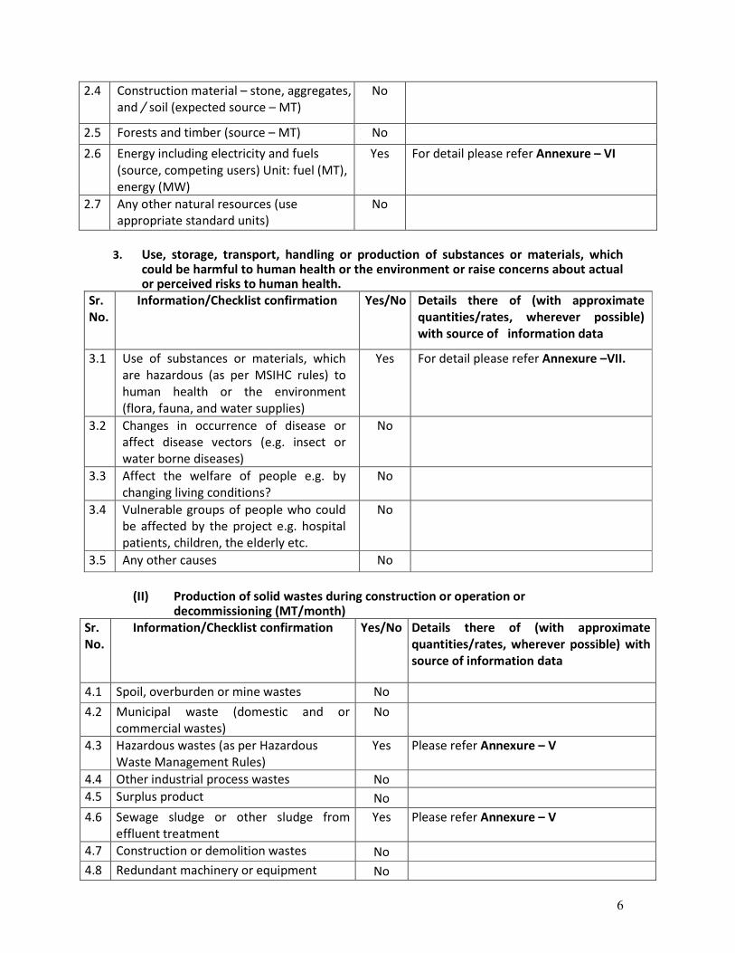
2.4 Construction material – stone, aggregates,
and / soil (expected source – MT)
No
2.5 Forests and timber (source – MT) No
2.6 Energy including electricity and fuels
(source, competing users) Unit: fuel (MT),
energy (MW)
Yes For detail please refer Annexure – VI
2.7 Any other natural resources (use
appropriate standard units)
No
3. Use, storage, transport, handling or production of substances or materials, which
could be harmful to human health or the environment or raise concerns about actual or perceived risks to human health.
Sr.
No.
Information/Checklist confirmation Yes/No Details there of (with approximate
quantities/rates, wherever possible)
with source of information data
3.1 Use of substances or materials, which
are hazardous (as per MSIHC rules) to
human health or the environment
(flora, fauna, and water supplies)
Yes For detail please refer Annexure –VII.
3.2 Changes in occurrence of disease or
affect disease vectors (e.g. insect or
water borne diseases)
No
3.3 Affect the welfare of people e.g. by
changing living conditions?
No
3.4 Vulnerable groups of people who could
be affected by the project e.g. hospital
patients, children, the elderly etc.
No
3.5 Any other causes No
(II) Production of solid wastes during construction or operation or
decommissioning (MT/month)
Sr.
No.
Information/Checklist confirmation Yes/No Details there of (with approximate
quantities/rates, wherever possible) with
source of information data
4.1 Spoil, overburden or mine wastes No
4.2 Municipal waste (domestic and or
commercial wastes)
No
4.3 Hazardous wastes (as per Hazardous
Waste Management Rules)
Yes Please refer Annexure – V
4.4 Other industrial process wastes No
4.5 Surplus product No
4.6 Sewage sludge or other sludge from
effluent treatment
Yes
Please refer Annexure – V
4.7 Construction or demolition wastes No
4.8 Redundant machinery or equipment No

7
4.9 Contaminated soils or other materials No
4.10 Agricultural wastes No
4.11 Other solid wastes Yes
Please refer Annexure – V
5. Release of pollutants or any hazardous, toxic or noxious substances to air (Kglhr)
Sr.
No.
Information/Checklist confirmation Yes/No Details there of (with approximate
quantities/rates, wherever possible) with
source of information data
5.1 Emissions from combustion of fossil
fuels from stationary or mobile
sources
Yes For details Please refer Annexure – VIII
5.2 Emissions from production processes Yes For details Please refer Annexure – VIII
5.3 Emissions from materials handling
storage or transport
Yes For details Please refer Annexure – VIII
5.4 Emissions from construction activities
including plant and equipment
No
5.5 Dust or odours from handling of
materials including construction
materials, sewage and waste
No
5.6 Emissions from incineration of waste No
5.7 Emissions from burning of waste in
open air e.g.slash materials,
construction debris)
No
5.8 Emissions from any other sources No
(III) Generation of Noise and Vibration, and Emissions of Light and Heat:
Sr.
No.
Information/Checklist confirmation Yes/No Details there of (with approximate
quantities/rates, wherever possible) with
source of information data with source of
information data
6.1 From operation of equipment e.g.
engines, ventilation plant, crushers
Yes Please refer Annexure – IX
6.2 From industrial or similar processes Yes Please refer Annexure – IX
6.3 From construction or demolition No
6.4 From blasting or piling No
6.5 From construction or operational traffic No
6.6 From lighting or cooling systems Yes Please refer Annexure – IX
6.7 From any other sources No
8
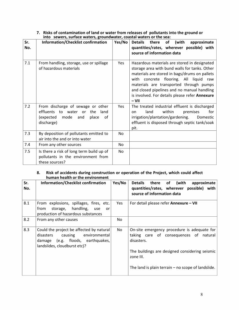
7. Risks of contamination of land or water from releases of pollutants into the ground or
into sewers, surface waters, groundwater, coastal waters or the sea:
Sr.
No.
Information/Checklist confirmation Yes/No Details there of (with approximate
quantities/rates, wherever possible) with
source of information data
7.1 From handling, storage, use or spillage
of hazardous materials
Yes Hazardous materials are stored in designated
storage area with bund walls for tanks. Other
materials are stored in bags/drums on pallets
with concrete flooring. All liquid raw
materials are transported through pumps
and closed pipelines and no manual handling
is involved. For details please refer Annexure
– VII
7.2 From discharge of sewage or other
effluents to water or the land
(expected mode and place of
discharge)
Yes The treated industrial effluent is discharged
on land within premises for
irrigation/plantation/gardening. Domestic
effluent is disposed through septic tank/soak
pit.
7.3 By deposition of pollutants emitted to
air into the and or into water
No
7.4 From any other sources No
7.5 Is there a risk of long term build up of
pollutants in the environment from
these sources?
No
8. Risk of accidents during construction or operation of the Project, which could affect
human health or the environment
Sr.
No.
Information/Checklist confirmation Yes/No Details there of (with approximate
quantities/rates, wherever possible) with
source of information data
8.1 From explosions, spillages, fires, etc.
from storage, handling, use or
production of hazardous substances
Yes For detail please refer Annexure – VII
8.2 From any other causes No
8.3 Could the project be affected by natural
disasters causing environmental
damage (e.g. floods, earthquakes,
landslides, cloudburst etc)?
No On-site emergency procedure is adequate for
taking care of consequences of natural
disasters.
The buildings are designed considering seismic
zone III.
The land is plain terrain – no scope of landslide.

9
9. Factors which should be considered (such as consequential development) which could
lead to environmental effects or the potential for cumulative impacts with other existing or planned activities in the locality
(IV) Environmental Sensitivity
Sr.
No.
Areas Name/
Identity
Aerial distance (within 15km.) Proposed project
location boundary
1 Areas protected under international
conventions, national or local legislation for
their ecological, landscape, cultural or other
related value
No Site is located in Dahej SEZ, Tal. Vagra, Dist.
Bharuch, Gujarat
2 Areas which important for are or sensitive Ecol
logical reasons – Wetlands, watercourses or
other water bodies, coastal zone, biospheres,
mountains, forests
No
3 Area used by protected, important or
sensitive Species of flora or fauna for breeding,
nesting, foraging, resting, over wintering,
migration
No
Sr. No.
Information/Checklist confirmation
Yes/No
Details there of (with approximate
quantities/rates, wherever possible) with
source of information data
9.1 Lead to development of supporting. utilities, ancillary development or development stimulated by the project which could have impact on the environment e.g.
• Supporting infrastructure (roads, power supply, waste or waste water treatment, etc.)
• housing development • extractive industry • supply industry • other
No Site is located in Dahej SEZ having the entire
required infrastructure.
This industrial zone is having existing road
infrastructure, power supply are to be
utilized.
Local people are employed and no housing is
required. For detail please refer Annexure – X
9.2 Lead to after-use of the site, which could
have an impact on the environment
No The treated industrial effluent is discharged
on land within premises for
irrigation/plantation/gardening. Domestic
effluent is disposed through septic tank/soak
pit. The hazardous waste is disposed to
approved TSDF site.
9.3 Set a precedent for later developments No
9.4 Have cumulative effects due to proximity
to other existing or planned projects with
similar effects
No
10
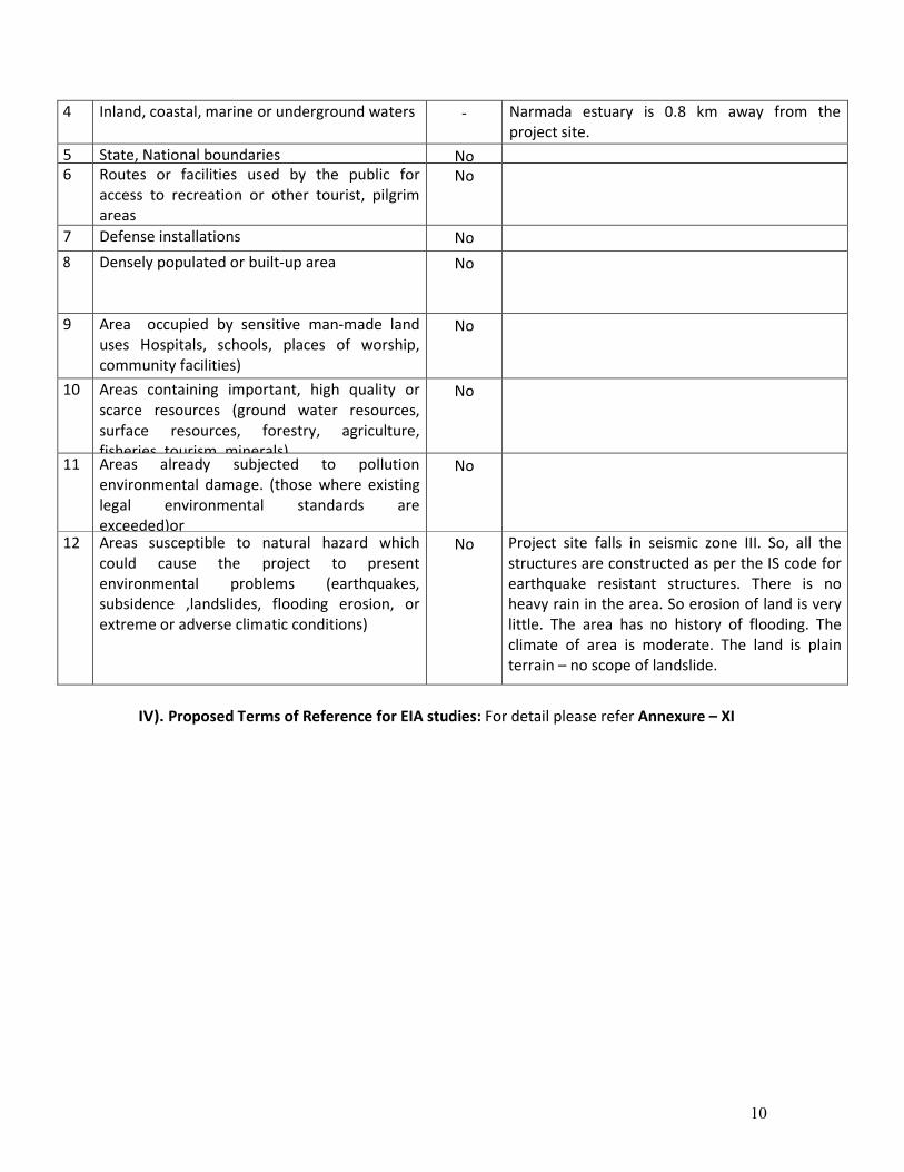
4 Inland, coastal, marine or underground waters - Narmada estuary is 0.8 km away from the
project site.
5 State, National boundaries No 6 Routes or facilities used by the public for
access to recreation or other tourist, pilgrim
areas
No
7 Defense installations No
8 Densely populated or built-up area No
9 Area occupied by sensitive man-made land
uses Hospitals, schools, places of worship,
community facilities)
No
10 Areas containing important, high quality or
scarce resources (ground water resources,
surface resources, forestry, agriculture,
fisheries, tourism, minerals)
No
11 Areas already subjected to pollution
environmental damage. (those where existing
legal environmental standards are
exceeded)or
No
12 Areas susceptible to natural hazard which
could cause the project to present
environmental problems (earthquakes,
subsidence ,landslides, flooding erosion, or
extreme or adverse climatic conditions)
No Project site falls in seismic zone III. So, all the
structures are constructed as per the IS code for
earthquake resistant structures. There is no
heavy rain in the area. So erosion of land is very
little. The area has no history of flooding. The
climate of area is moderate. The land is plain
terrain – no scope of landslide.
IV). Proposed Terms of Reference for EIA studies: For detail please refer Annexure – XI
11
12
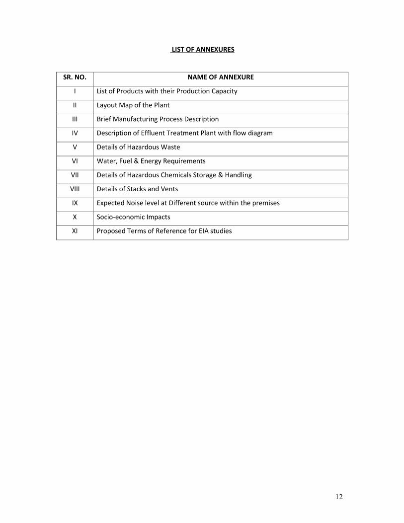
LIST OF ANNEXURES
SR. NO. NAME OF ANNEXURE
I List of Products with their Production Capacity
II Layout Map of the Plant
III Brief Manufacturing Process Description
IV Description of Effluent Treatment Plant with flow diagram
V Details of Hazardous Waste
VI Water, Fuel & Energy Requirements
VII Details of Hazardous Chemicals Storage & Handling
VIII Details of Stacks and Vents
IX Expected Noise level at Different source within the premises
X Socio-economic Impacts
XI Proposed Terms of Reference for EIA studies
13
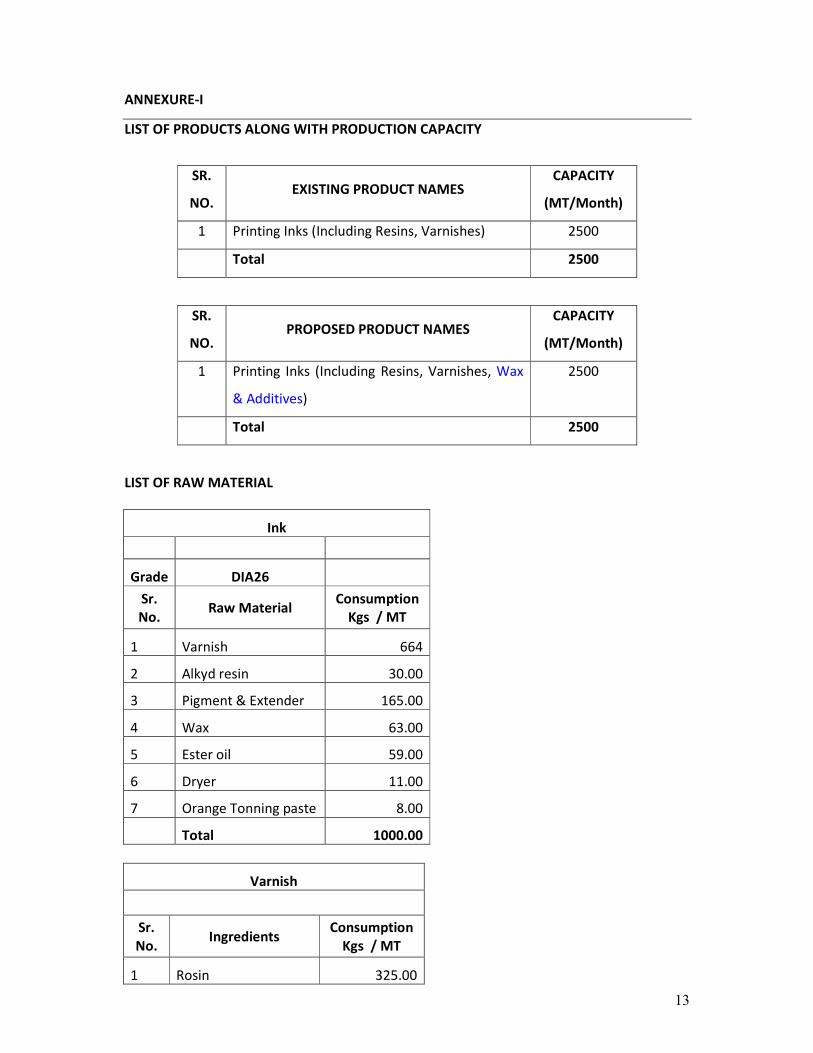
ANNEXURE-I
LIST OF PRODUCTS ALONG WITH PRODUCTION CAPACITY
SR.
NO. EXISTING PRODUCT NAMES
CAPACITY
(MT/Month)
1 Printing Inks (Including Resins, Varnishes) 2500
Total 2500
SR.
NO. PROPOSED PRODUCT NAMES
CAPACITY
(MT/Month)
1 Printing Inks (Including Resins, Varnishes, Wax
& Additives)
2500
Total 2500
LIST OF RAW MATERIAL
Ink
Grade DIA26
Sr.
No. Raw Material
Consumption
Kgs / MT
1 Varnish 664
2 Alkyd resin 30.00
3 Pigment & Extender 165.00
4 Wax 63.00
5 Ester oil 59.00
6 Dryer 11.00
7 Orange Tonning paste 8.00
Total 1000.00
Varnish
Sr.
No. Ingredients
Consumption
Kgs / MT
1 Rosin 325.00

14
2 PTBP 50.00
3 Catalyst 2.60
4 Antifoam 0.10
5 Formaldehyde 30.00
6 Maleic acid anhydride 20.00
7 Pentaerythritol 40.00
Resin sum 467.70
92% resin yield 430.28
8 Ester oil 250.00
9 Soya oil 340.00
10 Antiox 0.10
1020.4
Total (based on 98% varnish
yield) 1000.0
WAX & ADDITIVE
Grade PE Wax
Sr. No. Ingredients Consumption
Kgs / MT
1 Wax 300.00
2 Vegetable oil 698.00
3 Antioxidant 2.00
Total 1000.00
15
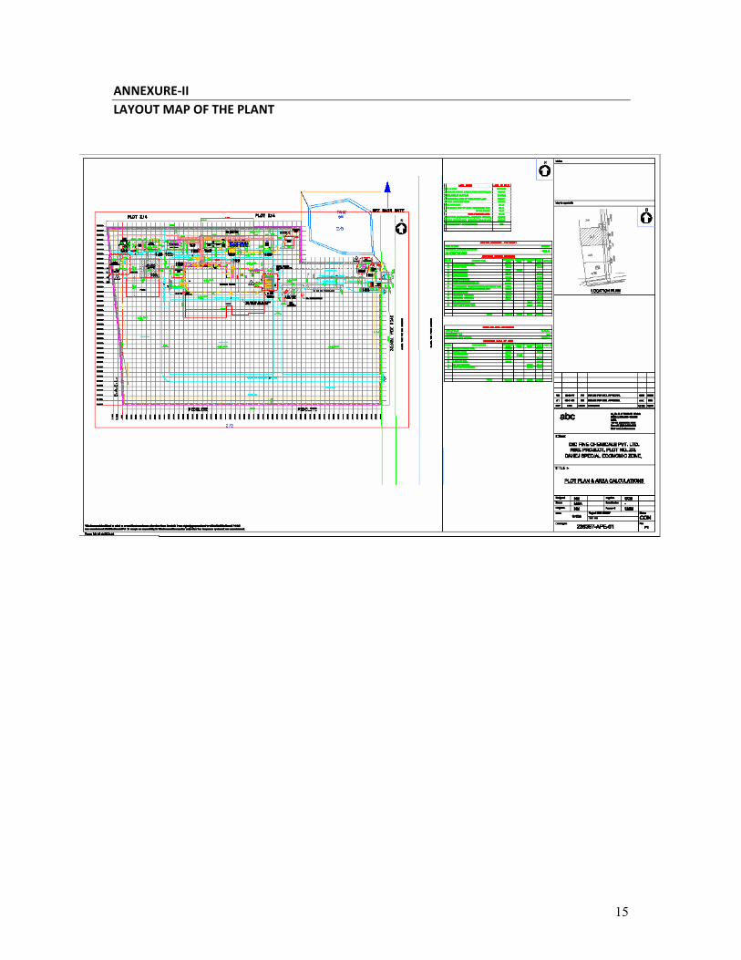
ANNEXURE-II
LAYOUT MAP OF THE PLANT
16
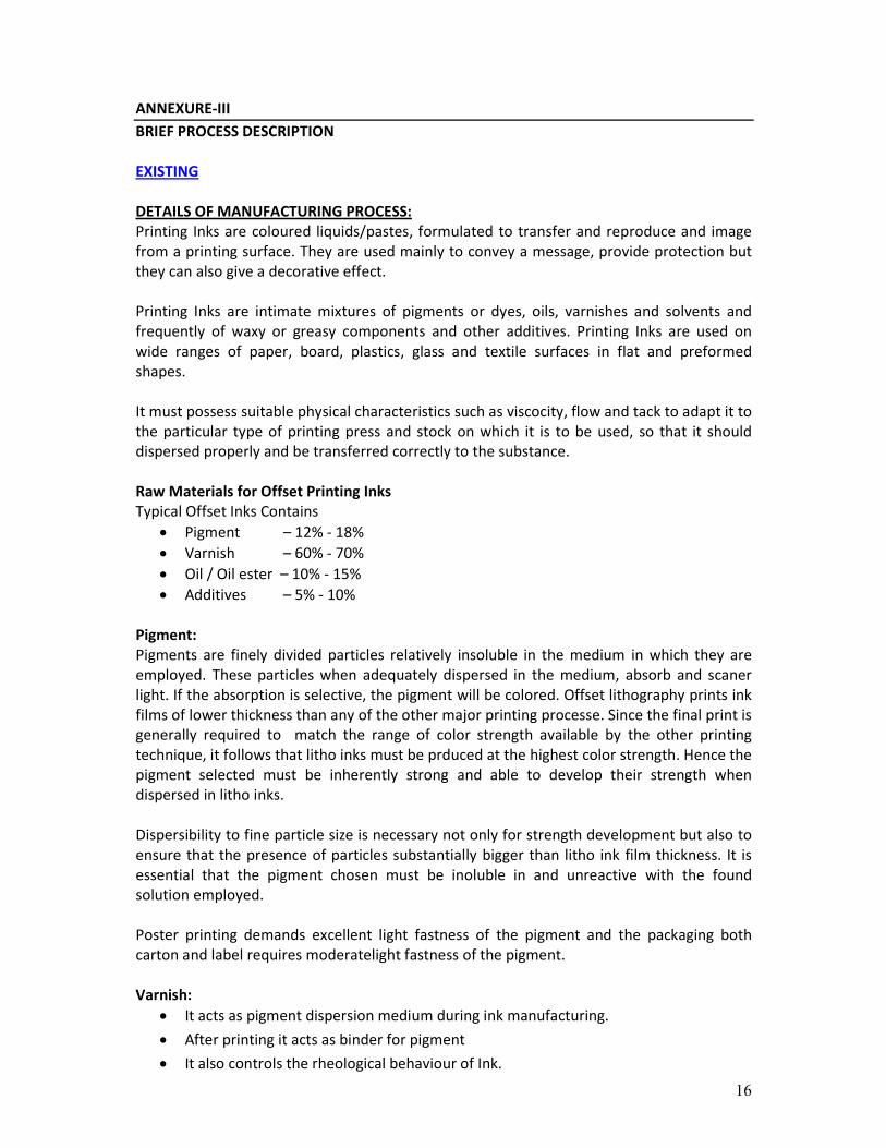
ANNEXURE-III
BRIEF PROCESS DESCRIPTION
EXISTING
DETAILS OF MANUFACTURING PROCESS:
Printing Inks are coloured liquids/pastes, formulated to transfer and reproduce and image
from a printing surface. They are used mainly to convey a message, provide protection but
they can also give a decorative effect.
Printing Inks are intimate mixtures of pigments or dyes, oils, varnishes and solvents and
frequently of waxy or greasy components and other additives. Printing Inks are used on
wide ranges of paper, board, plastics, glass and textile surfaces in flat and preformed
shapes.
It must possess suitable physical characteristics such as viscocity, flow and tack to adapt it to
the particular type of printing press and stock on which it is to be used, so that it should
dispersed properly and be transferred correctly to the substance.
Raw Materials for Offset Printing Inks
Typical Offset Inks Contains
• Pigment – 12% - 18%
• Varnish – 60% - 70%
• Oil / Oil ester – 10% - 15%
• Additives – 5% - 10%
Pigment:
Pigments are finely divided particles relatively insoluble in the medium in which they are
employed. These particles when adequately dispersed in the medium, absorb and scaner
light. If the absorption is selective, the pigment will be colored. Offset lithography prints ink
films of lower thickness than any of the other major printing processe. Since the final print is
generally required to match the range of color strength available by the other printing
technique, it follows that litho inks must be prduced at the highest color strength. Hence the
pigment selected must be inherently strong and able to develop their strength when
dispersed in litho inks.
Dispersibility to fine particle size is necessary not only for strength development but also to
ensure that the presence of particles substantially bigger than litho ink film thickness. It is
essential that the pigment chosen must be inoluble in and unreactive with the found
solution employed.
Poster printing demands excellent light fastness of the pigment and the packaging both
carton and label requires moderatelight fastness of the pigment.
Varnish:
• It acts as pigment dispersion medium during ink manufacturing.
• After printing it acts as binder for pigment
• It also controls the rheological behaviour of Ink.
17
Component of Varnish:
The Component of Varnish are as follows:
Vegetable Oil 25% - 30%
Resin 35% - 45%
Ester Oils 20% - 30%
Additives
• Gelling Agent
• Antioxidant
1% - 5%
Vegetable Oil:
In the litho ink generally two types of vegetable oils are there
Drying Oil: e.g. Linseed Oil, Tung Oil
Semidrying Oil: e.g. Soya Oil
The main features of the vegetable oil in the litho ink is to dry the ink on the substrate. It
also controls the pigment binding capacity of varnish and rheological behaviour of Ink.
Resin:
In the litho ink rosin modified phenolic resin is used. They have limited solubility in aliphatic
distillate which makes them ideal for use in quick setting varnish. They impart tough glossy
finishes with good chemical reisitance. They are compatible with alkyd and other resins to
produce high gloss inks with good rub resistance. They are used in heatset and web-offset
inks for their solvent release properties.
Vegetable Oil Esters:
In the lithographic ink vegetable oil ester (boiling range 2500C – 350
0C) having low solvent
power is used. Volatility restriction necessitate the use of vegetable oil esters in place of
mineral oils.
Additives:
As with all ink, a wide range of additive components are employed in small proportions to
modify the various printability and print performance. The main classes of additives are as
follows:
Driers:
The O2 – induced polymerization of the drying oils and the drying oil modified alkyds is
acclerated by incorporation of small quantities of certain metal compounds – which is called
Drier. The Drier catalysts are mainly based on transition metals that are able to exist in
stable forms in more than one oxidation state.
Waxes:
Waxes are incorporated into the litho inks to produce slip, stratch resistance and rub
resistance. The major chemical types of wax used in modern litho ink formulations are PE
(Polyethylene) for rub and stratch reisitance and PTFE (Polytetrafluoroethylene) for good
surface slip.

18
Antioxidant:
Antioxidants are used to control oxidation drying potentials of litho inks. The main types
are: Oximes (e.g. methyl ethyl ketone), Quinones (e.g. hydroquinone).
Litho Additives:
Litho additives are beneficial in controlling undesirable reaction between fount and ink that
might incertain circumstances hinder the good machine performance. One example of this is
the use of soluble salts of the tartaric acid and ethylene diamine tetra acetic acid which may
be able to form complexes with soluble calcium ion that may be present in certain pigment
grades or may originate from the coating of the paper and the board substrate.
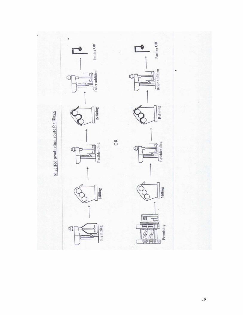
Manufacturing Process
Process Raw Materials Function
Premixing Base Varnish
Pigment
Ester Oil
Antioxidant
In the premixing stage, with the use of high speed
stirrers, pigment and the base varnish are mixed
together. The wetting process is complete with the
help of mechanical agitators and pigment particles are
dispersed with varnish base.
Milling Premix Base The pigment particles are reduced within 10 micron
size with the shearing action of the triple roll mill or
with bead mill. The process is continued until the
average particle size are reduced within 10 micron
limit.
Postblending Milling Base
Let Down Varnish
Additives
Ester Oils
In the postblending stage, with the butterfly stirrers,
the additive and the letdown varnish are mixed
together and the pigment concentration are reduced
as per the specified limit. All the specifications are
adjusted in this stage with the help of diluents like
Ester Oil.
Refining Postblend Mill Base The inks are passed through triple roll mills at a
reduced pressure, to ensure the particles size within
10 microns and also to give a continuous gloss finish of
the ink.
Drier Addition &
Pot Off
Final Product Driers are added in this stage to avoid spot drying of
inks during manufacturing and the inks are put in the
can.
19
20
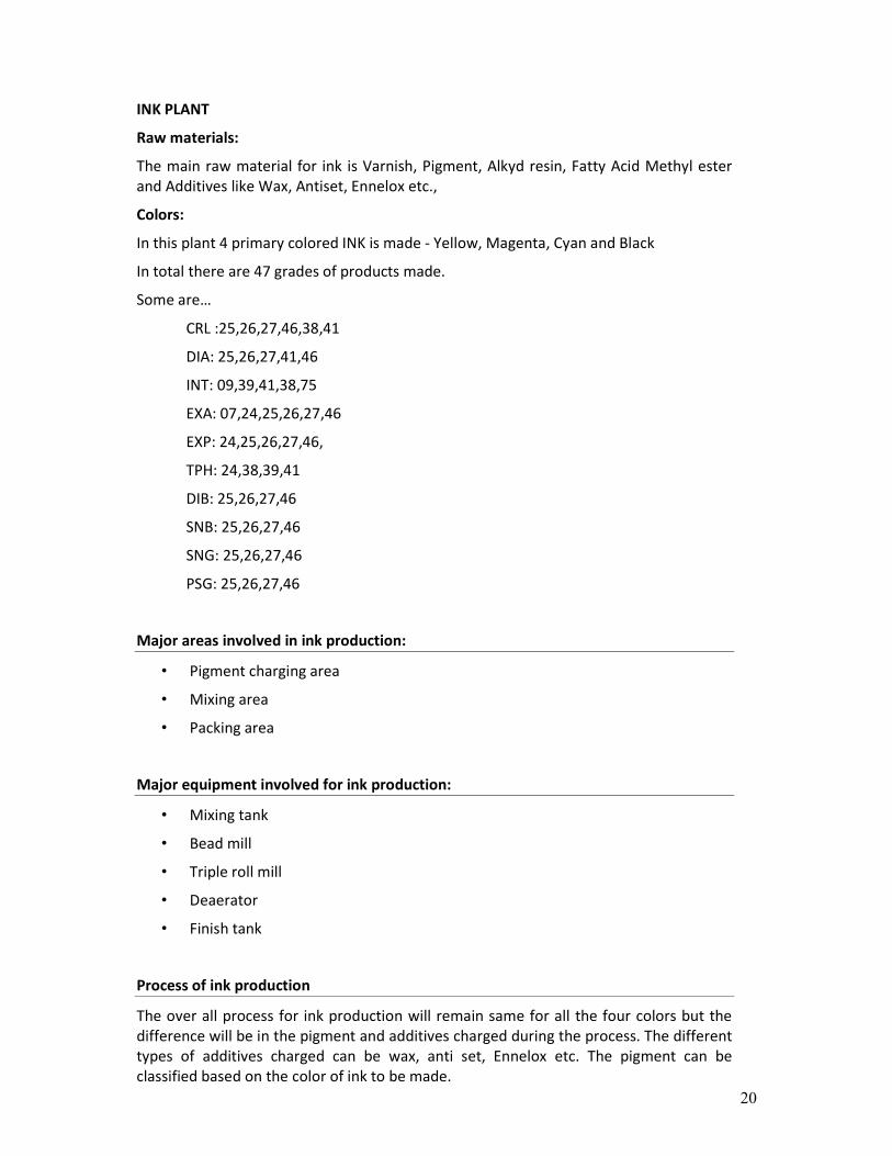
INK PLANT
Raw materials:
The main raw material for ink is Varnish, Pigment, Alkyd resin, Fatty Acid Methyl ester
and Additives like Wax, Antiset, Ennelox etc.,
Colors:
In this plant 4 primary colored INK is made - Yellow, Magenta, Cyan and Black
In total there are 47 grades of products made.
Some are…
CRL :25,26,27,46,38,41
DIA: 25,26,27,41,46
INT: 09,39,41,38,75
EXA: 07,24,25,26,27,46
EXP: 24,25,26,27,46,
TPH: 24,38,39,41
DIB: 25,26,27,46
SNB: 25,26,27,46
SNG: 25,26,27,46
PSG: 25,26,27,46
Major areas involved in ink production:
• Pigment charging area
• Mixing area
• Packing area
Major equipment involved for ink production:
• Mixing tank
• Bead mill
• Triple roll mill
• Deaerator
• Finish tank
Process of ink production
The over all process for ink production will remain same for all the four colors but the
difference will be in the pigment and additives charged during the process. The different
types of additives charged can be wax, anti set, Ennelox etc. The pigment can be
classified based on the color of ink to be made.
21
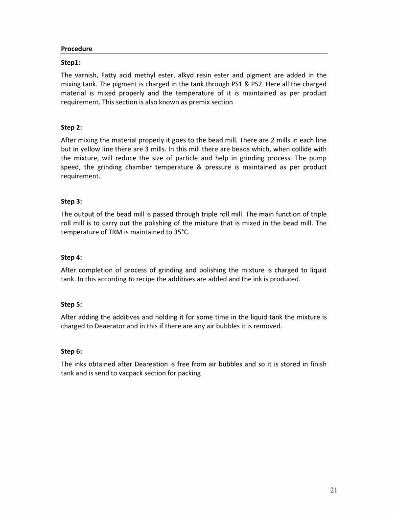
Procedure
Step1:
The varnish, Fatty acid methyl ester, alkyd resin ester and pigment are added in the
mixing tank. The pigment is charged in the tank through PS1 & PS2. Here all the charged
material is mixed properly and the temperature of it is maintained as per product
requirement. This section is also known as premix section
Step 2:
After mixing the material properly it goes to the bead mill. There are 2 mills in each line
but in yellow line there are 3 mills. In this mill there are beads which, when collide with
the mixture, will reduce the size of particle and help in grinding process. The pump
speed, the grinding chamber temperature & pressure is maintained as per product
requirement.
Step 3:
The output of the bead mill is passed through triple roll mill. The main function of triple
roll mill is to carry out the polishing of the mixture that is mixed in the bead mill. The
temperature of TRM is maintained to 35°C.
Step 4:
After completion of process of grinding and polishing the mixture is charged to liquid
tank. In this according to recipe the additives are added and the ink is produced.
Step 5:
After adding the additives and holding it for some time in the liquid tank the mixture is
charged to Deaerator and in this if there are any air bubbles it is removed.
Step 6:
The inks obtained after Deareation is free from air bubbles and so it is stored in finish
tank and is send to vacpack section for packing
22
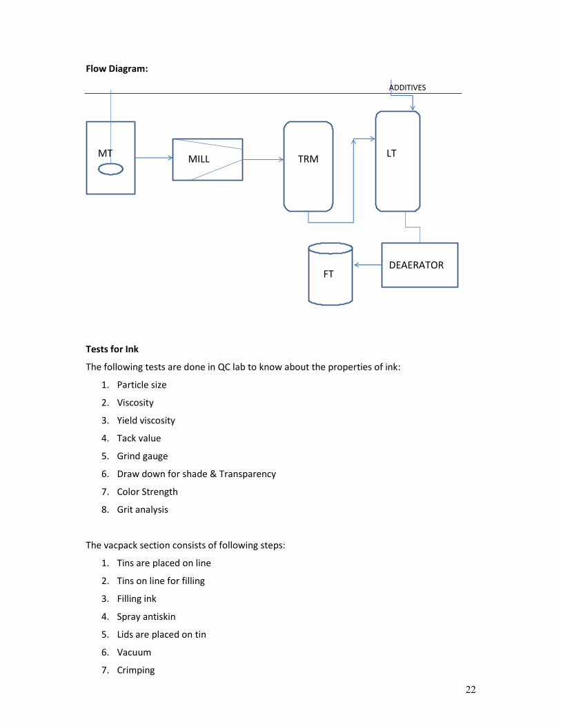
Flow Diagram:
Tests for Ink
The following tests are done in QC lab to know about the properties of ink:
1. Particle size
2. Viscosity
3. Yield viscosity
4. Tack value
5. Grind gauge
6. Draw down for shade & Transparency
7. Color Strength
8. Grit analysis
The vacpack section consists of following steps:
1. Tins are placed on line
2. Tins on line for filling
3. Filling ink
4. Spray antiskin
5. Lids are placed on tin
6. Vacuum
7. Crimping
MTMILL TRM
LT
DEAERATORFT
ADDITIVES
23
8. Labels are stuck (yellow (Pago) and white)
9. Boxes are folded
10. Tapping of box
11. Box are filled with the tins
12. Filled boxes are kept on pallets
These pallets are send to finished goods section and from there they are delivered to the
costumer through proper channel.
24
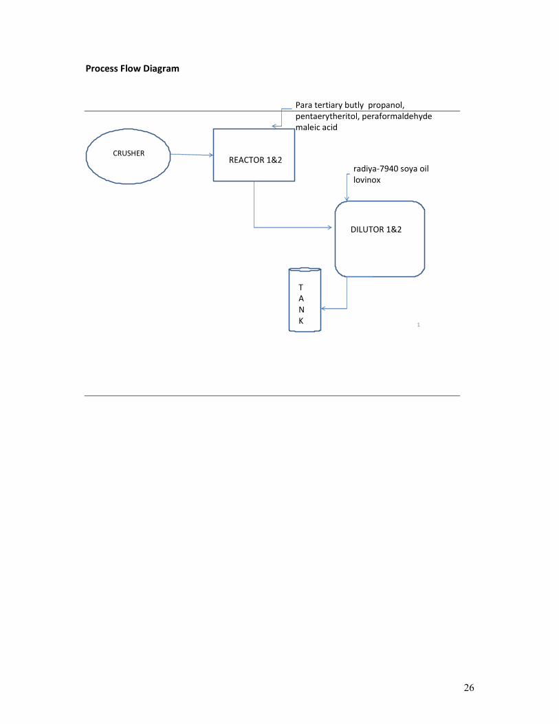
VARNISH PLANT
Raw material:
The raw material for varnish production is Rosin, paratertiary butyl propanol,
pentaerythritol, Para formaldehyde, malefic acid, antioxidant and catalysts.
Major steps involved in process:
• Rosin crusher
• Melting tank
• Reactor
• Dilutor
PPE’s used:
1. SCBA
2. Safety belt
3. Rubber gloves
4. Leather gloves
5. Paper suit
6. Aluminum gloves
7. Cotton gloves
8. Goggles & Dust mask
9. Ear plug
10. Face shield
Steps involved in production
Step 1:
Rosin-a natural product which is imported from china is the main raw material. Drums
of rosin are crushed in rosin crusher and the metal waste which is generated is send to
GI Scrap for disposal and the disposable slip are to be maintained. The rosin that is
crushed is fed to the melting tank where the rosin is melted at the temperature of 140
deg C. Hot oil is used to maintain the temperature. 33 drums of rosin is needed per
batch.
Step 2:
There are two reactors in the varnish plant .Reactor 1 & Reactor 2 with agitation. In the
reactor melted rosin is charged and the different temperature is maintained at various
stages. The Para tertiary butyl propanol, pentaerytheritol, Para formaldehyde, malefic
acid, antioxidant and catalysts are added at different stages as per process requirement.
25
Once the temperature of 265°C is achieved, the samples are sent to QC Lab for testing.
Once the testing is done and if it is as per the requirements QC LAB will suggest to break
the reaction as resin stage. For breaking the reaction vegetable oil and fatty acid methyl
ester is being added.
Step 3:
After breaking the reaction transfer the material to diluter with agitation. Keep the
temperature of dilutor as per process requirement. Add oil for final adjust to achieve the
required specification.
Step 4:
Send varnish to the varnish storage farm. After completion of process flush the lines by
nitrogen.
26
Process Flow Diagram
1
REACTOR 1&2
DILUTOR 1&2
T
A
N
K
Para tertiary butly propanol,
pentaerytheritol, peraformaldehyde
maleic acid
CRUSHER
radiya-7940 soya oil
lovinox
26
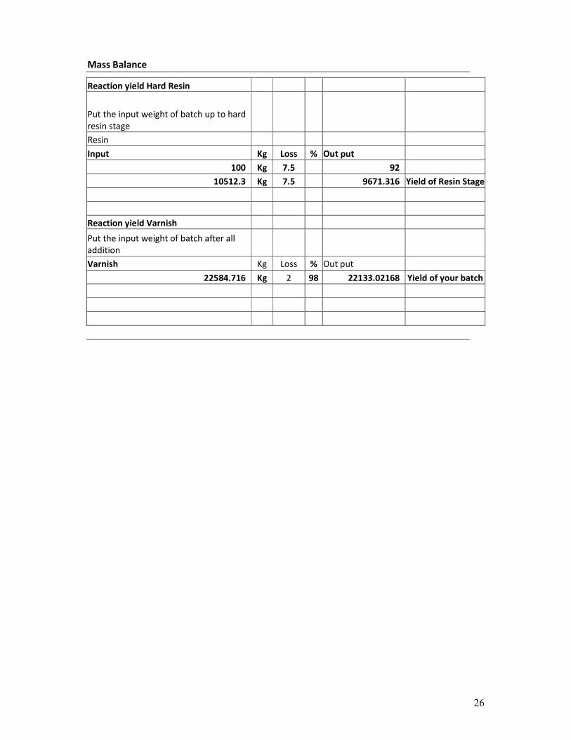
Mass Balance
Reaction yield Hard Resin
Put the input weight of batch up to hard
resin stage
Resin
Input Kg Loss % Out put
100 Kg 7.5 92
10512.3 Kg 7.5 9671.316 Yield of Resin Stage
Reaction yield Varnish
Put the input weight of batch after all
addition
Varnish Kg Loss % Out put
22584.716 Kg 2 98 22133.02168 Yield of your batch
27
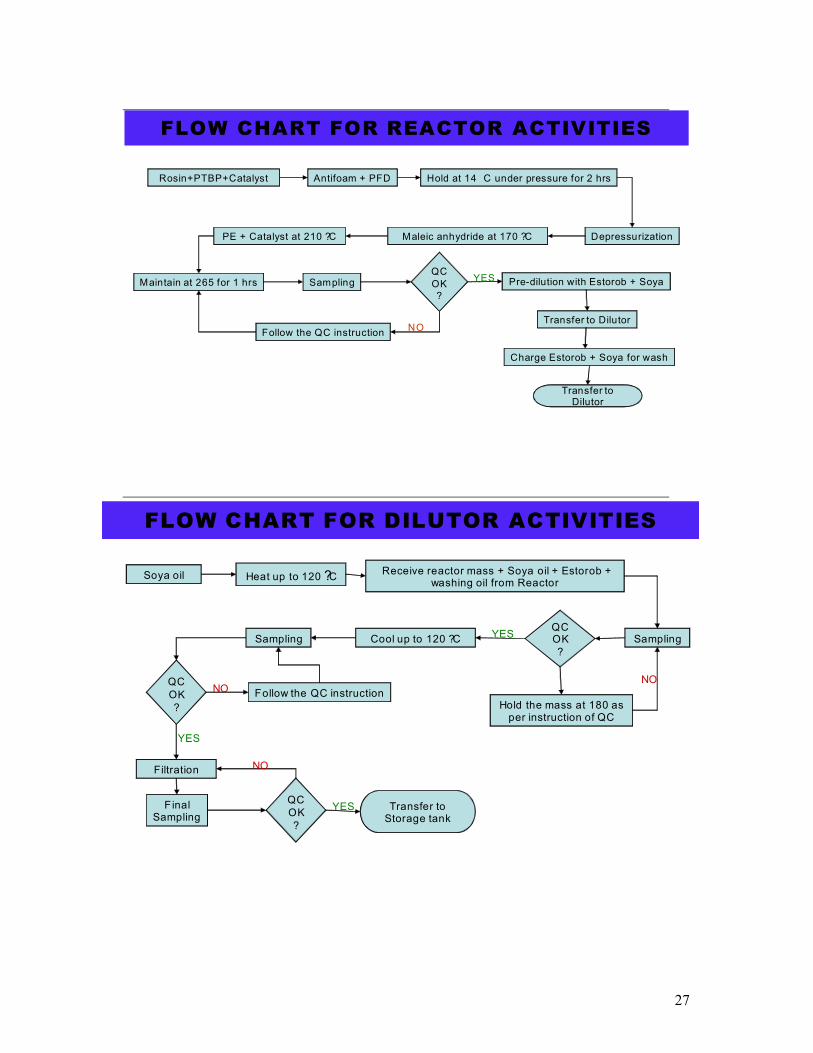
FLOW CHART FOR REACTOR ACTIVITIES
Rosin+PTBP+Catalyst Antifoam + PFD Hold at 14 C under pressure for 2 hrs
DepressurizationMaleic anhydride at 170 ?CPE + Catalyst at 210 ?C
Maintain at 265 for 1 hrs SamplingQC
OK
?
Follow the QC instructionNO
Pre-dilution with Estorob + Soya
Transfer to Dilutor
Charge Estorob + Soya for wash
Transfer to Dilutor
YES
FLOW CHART FOR DILUTOR ACTIVITIES
Soya oil Heat up to 120 ?CReceive reactor mass + Soya oil + Estorob +
washing oil from Reactor
SamplingCool up to 120 ?C
Filtration
Final Sampling
QC
OK
?
Follow the QC instruction
Transfer to Storage tank
QC OK
?
YESSampling
YES
YES
NO
QC
OK
?
NO
Hold the mass at 180 as per instruction of QC
NO

28
29
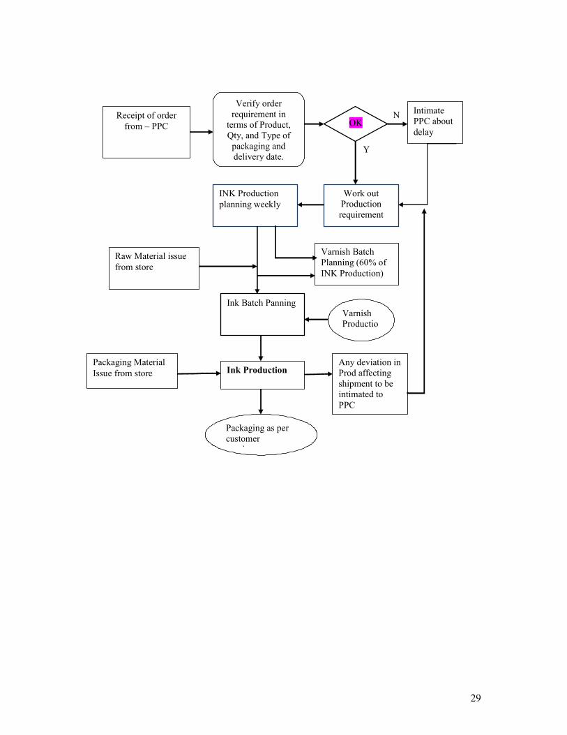
Receipt of order
from – PPC
Verify order
requirement in
terms of Product,
Qty, and Type of
packaging and
delivery date.
OK
Intimate
PPC about
delay
Work out
Production
requirement
INK Production
planning weekly
Varnish Batch
Planning (60% of
INK Production)
Raw Material issue
from store
Ink Batch Panning Varnish
Productio
n
Packaging Material
Issue from store Ink Production Any deviation in
Prod affecting
shipment to be
intimated to
PPC
Packaging as per
customer
requirement
Y
N
30
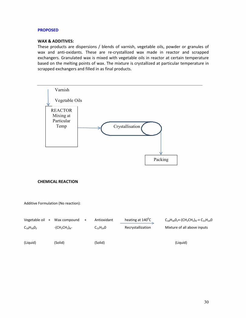
Additive Formulation (No reaction):
Vegetable oil + Wax compound + Antioxidant heating at 1400C C18H3002+-(CH2CH2)N-+ C15H240
C18H3002 -(CH2CH2)N- C15H240 Recrystallization Mixture of all above inputs
(Liquid) (Solid) (Solid) (Liquid)
PROPOSED
WAX & ADDITIVES:
These products are dispersions / blends of varnish, vegetable oils, powder or granules of
wax and anti-oxidants. These are re-crystallized wax made in reactor and scrapped
exchangers. Granulated wax is mixed with vegetable oils in reactor at certain temperature
based on the melting points of wax. The mixture is crystallized at particular temperature in
scrapped exchangers and filled in as final products.
CHEMICAL REACTION
REACTOR
Mixing at
Particular
Temp Crystallisation
Packing
Varnish
Vegetable Oils
31
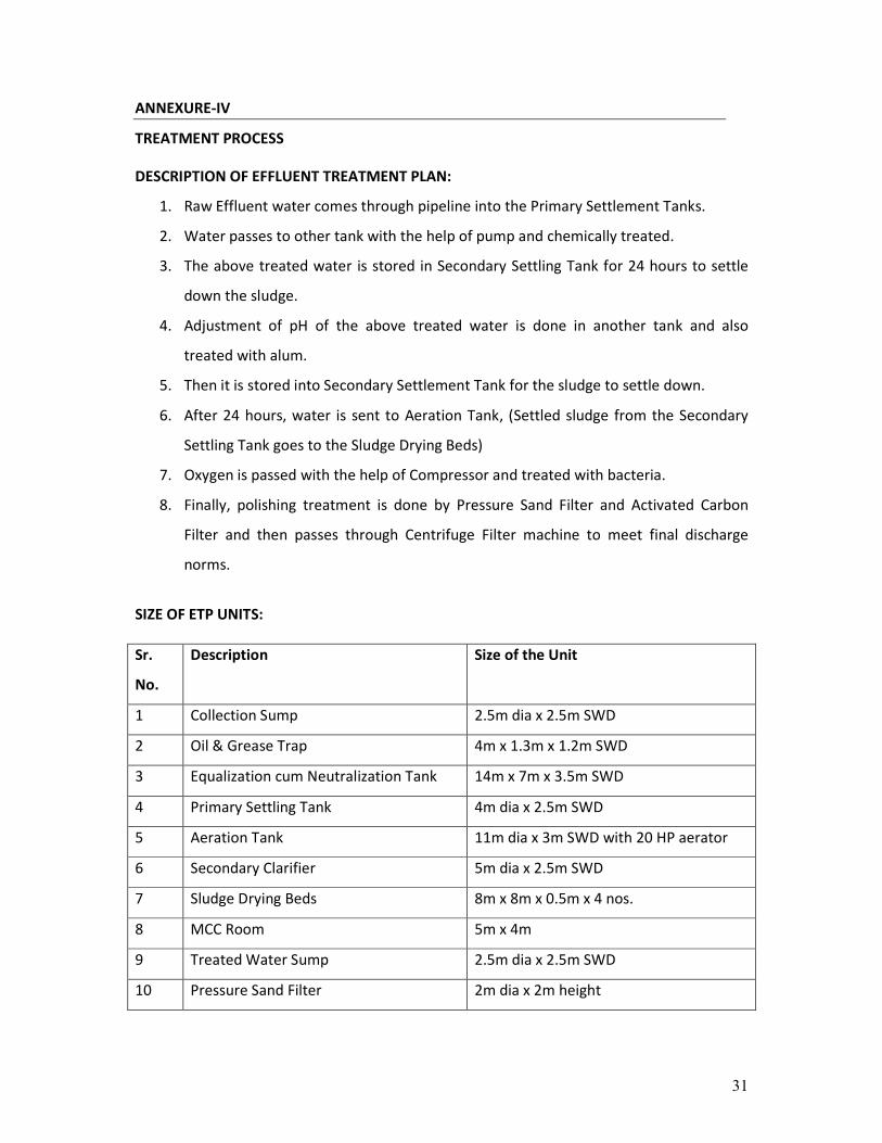
ANNEXURE-IV
TREATMENT PROCESS
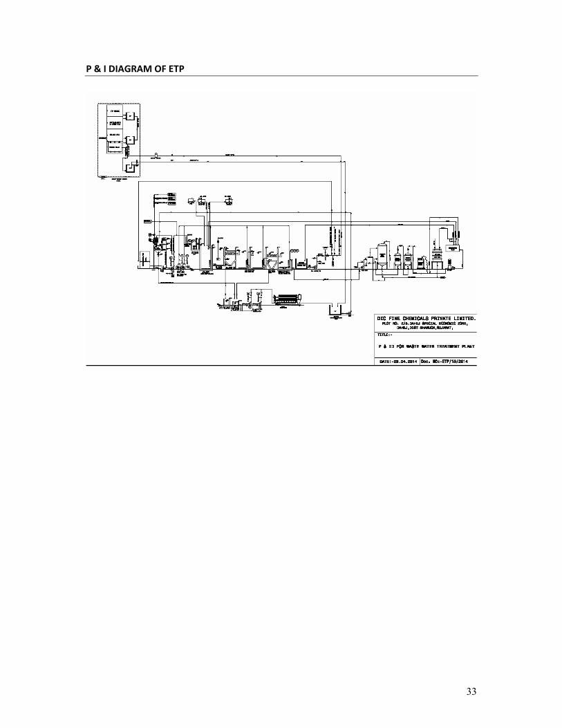
DESCRIPTION OF EFFLUENT TREATMENT PLAN:
1. Raw Effluent water comes through pipeline into the Primary Settlement Tanks.
2. Water passes to other tank with the help of pump and chemically treated.
3. The above treated water is stored in Secondary Settling Tank for 24 hours to settle
down the sludge.
4. Adjustment of pH of the above treated water is done in another tank and also
treated with alum.
5. Then it is stored into Secondary Settlement Tank for the sludge to settle down.
6. After 24 hours, water is sent to Aeration Tank, (Settled sludge from the Secondary
Settling Tank goes to the Sludge Drying Beds)
7. Oxygen is passed with the help of Compressor and treated with bacteria.
8. Finally, polishing treatment is done by Pressure Sand Filter and Activated Carbon
Filter and then passes through Centrifuge Filter machine to meet final discharge
norms.
SIZE OF ETP UNITS:
Sr.
No.
Description Size of the Unit
1 Collection Sump 2.5m dia x 2.5m SWD
2 Oil & Grease Trap 4m x 1.3m x 1.2m SWD
3 Equalization cum Neutralization Tank 14m x 7m x 3.5m SWD
4 Primary Settling Tank 4m dia x 2.5m SWD
5 Aeration Tank 11m dia x 3m SWD with 20 HP aerator
6 Secondary Clarifier 5m dia x 2.5m SWD
7 Sludge Drying Beds 8m x 8m x 0.5m x 4 nos.
8 MCC Room 5m x 4m
9 Treated Water Sump 2.5m dia x 2.5m SWD
10 Pressure Sand Filter 2m dia x 2m height
32
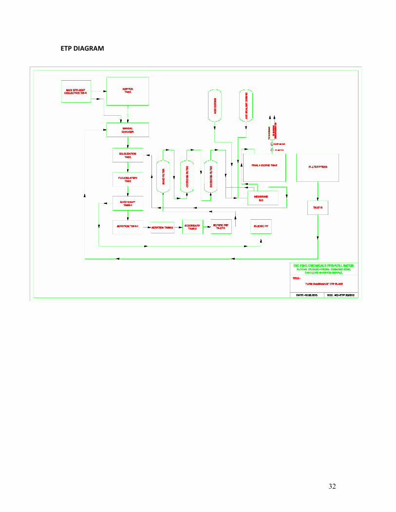
ETP DIAGRAM
33
P & I DIAGRAM OF ETP

34
ANNEXURE-V
HAZARDOUS WASTE GENERATION AND DISPOSAL
SR.
NO.
NAME OF WASTE CATEGORY QUANTITY
(MT/ANNUM)
MODE OF DISPOSAL
1 Spent Oil 5.1 2 Collection, Storage, Transportation, and
send to GPCB approved recycler for
Selling to Registered Refiner
2 ETP Sludge 34.3 9
Collection, Storage, Transportation and
Disposal to TSDF site of BEIL
Discarded Drums/
Containers/Barrels,
Liners
1200
Nos./Month
Jumbo Bags 1 Nos./Month
3
Empty Tins/Plastic
Tins
33.3
5 Nos./Month
Collection, Storage, Decontamination,
transportation and send to authorized
Trader
4 Empty Paper
Bags/Plastic/Box/
Pitch Board etc.
--- 13 Collection, Storage, Decontamination,
transportation and send to authorized
Trader
5 Wood Scrap 21.1 72 Collection, Storage, Decontamination,
transportation and send to authorized
Trader
6 Waste Ink Spillage
Waste/Waste Varnish
Spillage
21.1 1
Collection, Storage, Decontamination,
transportation and send to authorized
Trader
7 Contaminated Cotton
Waste
21.1 360 Collection, Storage, Decontamination,
transportation and send to authorized
Trader
8 Filter Bags Socked
with Ink and Varnish
21.1 34 Collection, Storage, Decontamination,
transportation and send to authorized
Trader
9 Cartridge 21.1 0.5 Collection, Storage, transportation and
send to GPCB approved recycler
NOTE:
After Proposed Expansion by addition of Wax & Additives there shall not be any increase
in Hazardous Waste Generation.
35
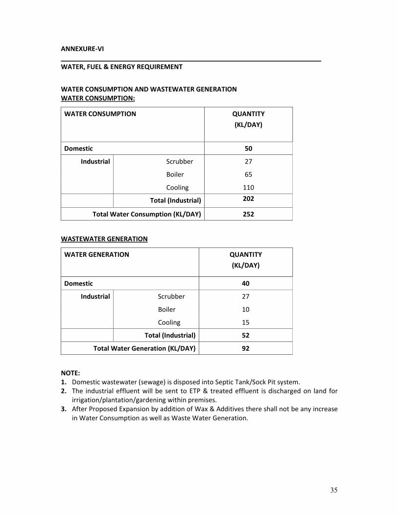
ANNEXURE-VI
_______________________________________________________________________
WATER, FUEL & ENERGY REQUIREMENT
WATER CONSUMPTION AND WASTEWATER GENERATION
WATER CONSUMPTION:
WATER CONSUMPTION QUANTITY
(KL/DAY)
Domestic 50
Scrubber 27
Boiler 65
Industrial
Cooling 110
Total (Industrial) 202
Total Water Consumption (KL/DAY) 252
WASTEWATER GENERATION
WATER GENERATION QUANTITY
(KL/DAY)
Domestic 40
Scrubber 27
Boiler 10
Industrial
Cooling 15
Total (Industrial) 52
Total Water Generation (KL/DAY) 92
NOTE:
1. Domestic wastewater (sewage) is disposed into Septic Tank/Sock Pit system.
2. The industrial effluent will be sent to ETP & treated effluent is discharged on land for
irrigation/plantation/gardening within premises.
3. After Proposed Expansion by addition of Wax & Additives there shall not be any increase
in Water Consumption as well as Waste Water Generation.
36
WATER BALANCE DIAGRAM
Raw Water
252 KL/day
Scrubber
27 KL/day
Boiler
65 KL/day
Cooling
110 KL/day
Domestic
50 KL/day
27KL/day
10 KL/day
15KL/day
Septic Tank
/
Soak Pit
ETP
52 KL/day
52 KL/day
Treated effluent is discharged on land for
irrigation/plantation/gardening within
premises
40 KL/day
37
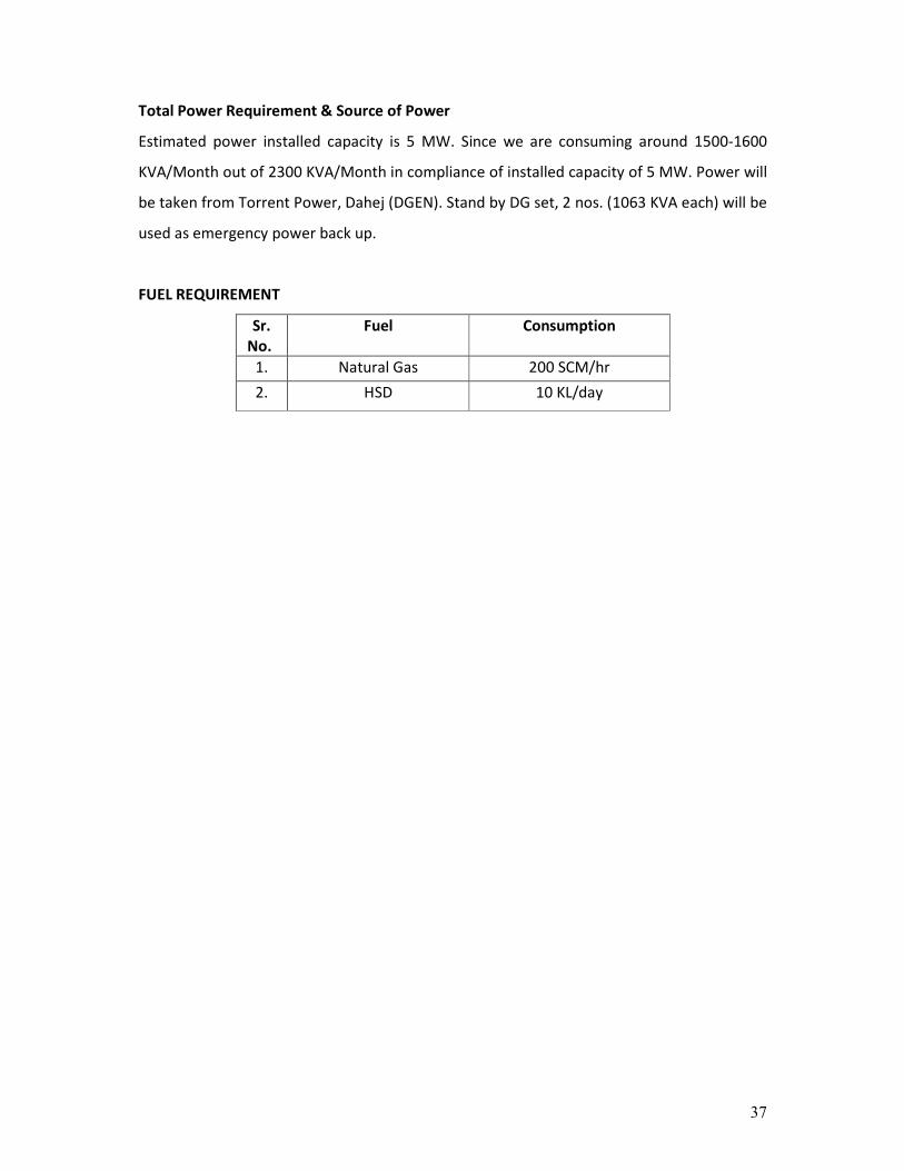
Total Power Requirement & Source of Power
Estimated power installed capacity is 5 MW. Since we are consuming around 1500-1600
KVA/Month out of 2300 KVA/Month in compliance of installed capacity of 5 MW. Power will
be taken from Torrent Power, Dahej (DGEN). Stand by DG set, 2 nos. (1063 KVA each) will be
used as emergency power back up.
FUEL REQUIREMENT
Sr.
No.
Fuel Consumption
1. Natural Gas 200 SCM/hr
2. HSD 10 KL/day

38
ANNEXURE-VII
_______________________________________________________________________
STORAGE DETAILS OF HAZARDOUS CHEMICALS
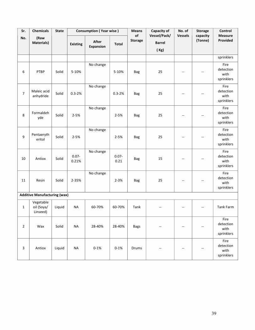
Consumption ( Year wise ) Sr.
No.
Chemicals
(Raw
Materials)
State
Existing After
Expansion Total
Means
of
Storage
Capacity of
Vessel/Pack/
Barrel
( Kg)
No. of
Vessels
Storage
capacity
(Tonne)
Control
Measure
Provided
Ink Manufacturing
1 Varnish Liquid 65-70% No change 65-70% Tanks 60000 9 540
Fire
detection
with
sprinklers
2
Pigment
(Black/Yell
ow/Red/Bl
ue/Extend
er)
Solid 20-32% No change 20-32% Bags 20/25/400/
500/800 -- --
Fire
detection
with
sprinklers
3 Alkyd
Resin Liquid 2-20% No change 2-20% Tanks 60000 3 170
Fire
detection
with
sprinklers
4 Wax &
Additives Paste 2-10% No change 2-10% Drums 200 -- --
Fire
detection
with
sprinklers
5 Vegetable
oil ester Liquid 2-5% No change 2-5% Tanks 60000 7 420 Tank farm
6 Tonner Paste 1-10% No change 1-10% Drum 200 -- -- Tank farm
7 Antiox Liquid 0.5-2% No change 0.5-2% Tot 1100 -- -- Tank farm
8 Wetting
agent Liquid 0.2-1% No change 0.2-1% Tot 1000 -- --
Tank farm
9 Dryer Liquid 1-4.5% No change 1-4.5% Drum 200 -- -- Tank farm
Varnish Manufacturing
1 Gum Rosin Solid 22-35% No change 30-35% Drums 200 -- --
Fire
detection
with
sprinklers
2
Vegetable
oil (Soya/
Linseed/
Wood)
Liquid 32-38% No change 42-58% Tank 60000 -- -- Tank farm
3 Vegetable
oil ester Liquid 10-22% No change 10-22% Tank 60000 -- -- Tank farm
4 Mineral Oil Liquid 16% No change 16% Tank 60000 -- -- Tank farm
5
Catalyst
(CaO/ZNO
2/MgO
Solid 0.01-
0.05% No change 0.01-
0.05% Bags 20 -- --
Fire
detection
with
39
Consumption ( Year wise ) Sr.
No.
Chemicals
(Raw
Materials)
State
Existing After
Expansion Total
Means
of
Storage
Capacity of
Vessel/Pack/
Barrel
( Kg)
No. of
Vessels
Storage
capacity
(Tonne)
Control
Measure
Provided
sprinklers
6 PTBP Solid 5-10%
No change
5-10% Bag 25 -- --
Fire
detection
with
sprinklers
7 Maleic acid
anhydride Solid 0.3-2%
No change
0.3-2% Bag 25 -- --
Fire
detection
with
sprinklers
8 Formaldeh
yde Solid 2-5%
No change
2-5% Bag 25 -- --
Fire
detection
with
sprinklers
9 Pentaeryth
eritol Solid 2-5%
No change
2-5% Bag 25 -- --
Fire
detection
with
sprinklers
10 Antiox Solid 0.07-
0.21%
No change
0.07-
0.21 Bag 15 -- --
Fire
detection
with
sprinklers
11 Resin Solid 2-35%
No change
2-3% Bag 25 -- --
Fire
detection
with
sprinklers
Additive Manufacturing (wax)
1
Vegetable
oil (Soya/
Linseed)
Liquid NA 60-70% 60-70% Tank -- -- -- Tank Farm
2 Wax Solid NA 28-40% 28-40% Bags -- -- --
Fire
detection
with
sprinklers
3 Antiox Liquid NA 0-1% 0-1% Drums -- -- --
Fire
detection
with
sprinklers
40
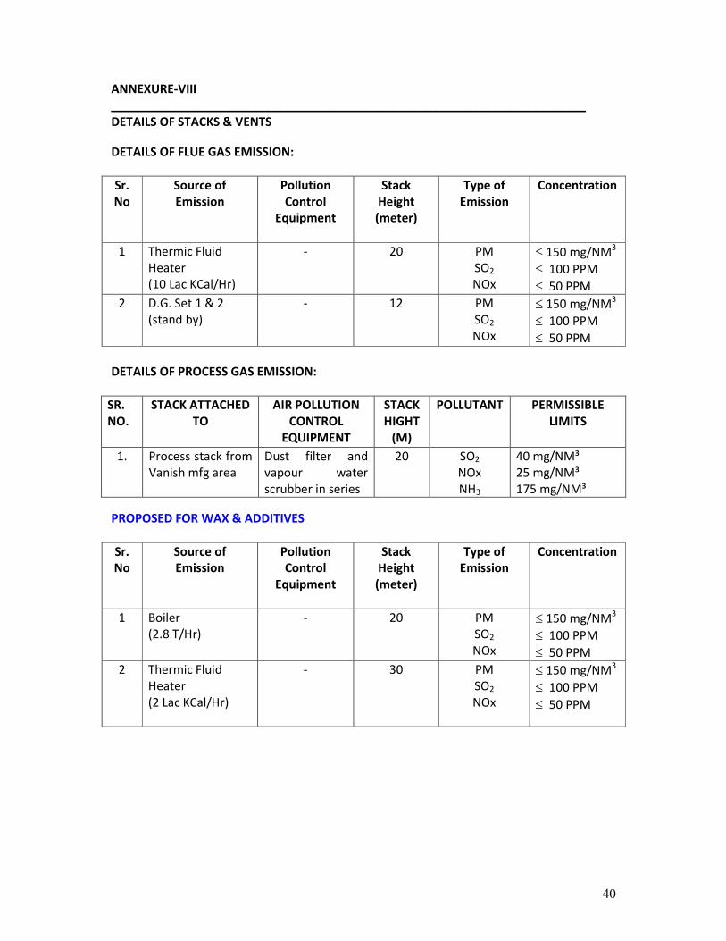
ANNEXURE-VIII
_______________________________________________________________________
DETAILS OF STACKS & VENTS
DETAILS OF FLUE GAS EMISSION:
Sr.
No
Source of
Emission
Pollution
Control
Equipment
Stack
Height
(meter)
Type of
Emission
Concentration
1 Thermic Fluid
Heater
(10 Lac KCal/Hr)
- 20 PM
SO2
NOx
≤ 150 mg/NM3
≤ 100 PPM
≤ 50 PPM
2 D.G. Set 1 & 2
(stand by)
- 12 PM
SO2
NOx
≤ 150 mg/NM3
≤ 100 PPM
≤ 50 PPM
DETAILS OF PROCESS GAS EMISSION:
SR.
NO.
STACK ATTACHED
TO
AIR POLLUTION
CONTROL
EQUIPMENT
STACK
HIGHT
(M)
POLLUTANT PERMISSIBLE
LIMITS
1. Process stack from
Vanish mfg area
Dust filter and
vapour water
scrubber in series
20 SO2
NOx
NH3
40 mg/NM³
25 mg/NM³
175 mg/NM³
PROPOSED FOR WAX & ADDITIVES
Sr.
No
Source of
Emission
Pollution
Control
Equipment
Stack
Height
(meter)
Type of
Emission
Concentration
1 Boiler
(2.8 T/Hr)
- 20 PM
SO2
NOx
≤ 150 mg/NM3
≤ 100 PPM
≤ 50 PPM
2 Thermic Fluid
Heater
(2 Lac KCal/Hr)
- 30 PM
SO2
NOx
≤ 150 mg/NM3
≤ 100 PPM
≤ 50 PPM
41
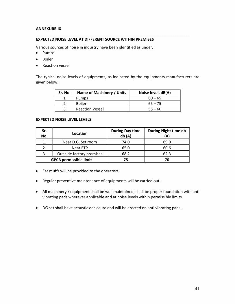
ANNEXURE-IX
_______________________________________________________________________
EXPECTED NOISE LEVEL AT DIFFERENT SOURCE WITHIN PREMISES
Various sources of noise in industry have been identified as under,
• Pumps
• Boiler
• Reaction vessel
The typical noise levels of equipments, as indicated by the equipments manufacturers are
given below:
Sr. No. Name of Machinery / Units Noise level, dB(A)
1 Pumps 60 – 65
2 Boiler 65 – 75
3 Reaction Vessel 55 – 60
EXPECTED NOISE LEVEL LEVELS:
Sr.
No. Location
During Day time
db (A)
During Night time db
(A)
1. Near D.G. Set room 74.0 69.0
2. Near ETP 65.0 60.6
3. Out side factory premises 68.2 62.3
GPCB permissible limit 75 70
• Ear muffs will be provided to the operators.
• Regular preventive maintenance of equipments will be carried out.
• All machinery / equipment shall be well maintained, shall be proper foundation with anti
vibrating pads wherever applicable and at noise levels within permissible limits.
• DG set shall have acoustic enclosure and will be erected on anti vibrating pads.
42
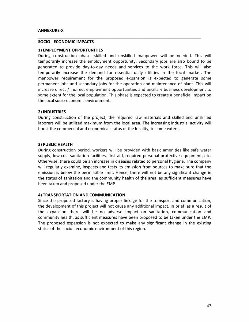
ANNEXURE-X
_______________________________________________________________________
SOCIO - ECONOMIC IMPACTS
1) EMPLOYMENT OPPORTUNITIES
During construction phase, skilled and unskilled manpower will be needed. This will
temporarily increase the employment opportunity. Secondary jobs are also bound to be
generated to provide day-to-day needs and services to the work force. This will also
temporarily increase the demand for essential daily utilities in the local market. The
manpower requirement for the proposed expansion is expected to generate some
permanent jobs and secondary jobs for the operation and maintenance of plant. This will
increase direct / indirect employment opportunities and ancillary business development to
some extent for the local population. This phase is expected to create a beneficial impact on
the local socio-economic environment.
2) INDUSTRIES
During construction of the project, the required raw materials and skilled and unskilled
laborers will be utilized maximum from the local area. The increasing industrial activity will
boost the commercial and economical status of the locality, to some extent.
3) PUBLIC HEALTH
During construction period, workers will be provided with basic amenities like safe water
supply, low cost sanitation facilities, first aid, required personal protective equipment, etc.
Otherwise, there could be an increase in diseases related to personal hygiene. The company
will regularly examine, inspects and tests its emission from sources to make sure that the
emission is below the permissible limit. Hence, there will not be any significant change in
the status of sanitation and the community health of the area, as sufficient measures have
been taken and proposed under the EMP.
4) TRANSPORTATION AND COMMUNICATION
Since the proposed factory is having proper linkage for the transport and communication,
the development of this project will not cause any additional impact. In brief, as a result of
the expansion there will be no adverse impact on sanitation, communication and
community health, as sufficient measures have been proposed to be taken under the EMP.
The proposed expansion is not expected to make any significant change in the existing
status of the socio - economic environment of this region.
43
ANNEXURE-XI
_______________________________________________________________________
PROPOSED TERMS OF REFERENCE FOR EIA STUDIES
OBJECTIVES
The main objectives of the study are:
1) To assess the background environmental status,
2) To identify potential sources of pollution,
3) To predict and evaluate the impact on environment along with pollution control
measures taken and
4) To prepare a comprehensive Environment Management Plan and Disaster
Management Plan.
SCOPE OF SERVICES
GENERAL
The Environmental Impact Assessment of the project shall examine the project’s potential
negative and positive environmental impacts and shall recommend any measure needed to
prevent, minimize, mitigate or compensate for adverse impacts and improve environmental
performance of the schemes. It should prevent future liabilities or expensive alternatives in
the project. Impact assessment requires as a sound knowledge and understanding of the
baseline situation and of the autonomous development situation.
The conduct of the assessment will be governed and content of the report will be specified
by following legislation and other relevant regulation, if applicable.
• Environmental Protection Act – 1986
• Water (Prevention and Control) of Pollution Act – 1974
• Air (Prevention and Control) of Pollution Act – 1981
• Hazardous Waste (Management & Handling) Amended Rules - 2003
• Environmental Impact Assessment Notification – 2006
METHODOLOGIES FOR EIA
Taking into consideration proposed project activities and guidelines, an area of 5 km radius
from the center of the project shall be selected and is designated as the study area for the
purpose of rapid EIA studies.
BASE LINE CONDITION
The samples of ambient air, ground and surface water and soil shall be collected and
analyzed as per the standard methods for establishing the baseline data and to determine
the impact of proposed activity on the same.
AMBIENT AIR ENVIRONMENT
The air environment around the plant shall be studied by setting up locations within the
study area of 5 km radius from the project site and collection and monitoring the site
specific meteorological data, viz. wind speed, wind direction, humidity, rainfall and ambient
temperature was carried out. Design of network for ambient air quality monitoring locations
is based on guidelines provided by CPCB. The ambient air samples shall be collected and
analyzed for Respirable Suspended Particulate Matter (RSPM-PM10), Respirable Suspended
Particulate Matter (RSPM-PM2.5), Sulphur Dioxide (SO2), Oxides of Nitrogen (NOx), Ozone
(O3), Lead (Pb), Carbon Monoxide (CO), Ammonia (NH3), Benzene (C6H6), Benzo (a) Pyrene
44
(BaP), Arsenic (AS) & Nickel (Ni) for identification, prediction, evaluation and assessment of
potential impact on ambient air environment.
GROUND AND SURFACE WATER ENVIRONMENT
To assess the physico-chemical quality of the water, a number of water samples shall be
collected and analyzed for pollution parameters viz., pH, TDS, Turbidity, BOD3, COD,
Fluorides, Chlorides, Sulphates, Nitrates, Ammonical Nitrogen, Hardness, Alkalinity, Oil &
Grease and some heavy metals in order to find out the contamination, if any.
NOISE ENVIRONMENT
Noise pollution survey shall be conducted in the study zone for evaluating existing status.
The anticipated noise sources were industrial activities, which are likely to be increased due
to proposed activity. Noise levels shall also recorded in surrounding villages for evaluating
general scenario of the study area. Hourly equivalent sound levels (Leq) shall also recorded
for calculating Day and Night noise levels in the surrounding villages.
SOIL ENVIRONMENT
Soil sampling and analysis shall be carried out to assess physico-chemical characteristics of
the soils and delineate existing cropping pattern, existing land use and topography, within
the study area.
BIOLOGICAL ENVIRONMENT
Keeping in view, the importance of biological component of total environment due to the
proposed project, biological characterization of terrestrial and aquatic environments,
changes in species diversity of flora and fauna in terrestrial as well as aquatic systems shall
be studied for impact analysis due to proposed project activity, if any.
SOCIO-ECONOMIC ENVIRONMENT
Demographic and related socio-economic data shall be collected from census handbook to
assess socio-economic status of the study area. Assessment of impact on significant
historical, cultural, and archeological sites/places in the area and economic and employment
benefit arisen out from the project shall be given special attention.
IDENTIFICATION OF POLLUTION SOURCE
Detailed study of manufacturing process for post expansion scenario shall be carried out
along with input and output of materials, water, and wastewater as well as infrastructure
facilities available.
EVALUATION OF POLLUTION CONTROL AND ENVIRONMENTAL MANAGEMENT SYSTEM
The qualitative and quantitative analysis of various pollution sources as well as evaluation of
pollution control system shall be carried out.
EVALUATION OF IMPACT
A comprehensive evaluation of environmental impact with reference to proposed expansion
activities shall be carried out.

45
PREPARATION OF ENVIRONMENTAL MANAGEMENT PLAN
A comprehensive Environmental Management Plan shall be prepared covering all the
aspects of pollution prevention measures, Air and Water Pollution Control measures,
Hazardous Waste Management, Environmental Surveillance and Environmental
Management Plan.