geared and gearless elevator drive
TRANSCRIPT

FOLD
Geared and Gearless Elevator Drive
L1000A
2
Experience & Innovation ................2
Advanced Motor / Drive Technology ......................................3-5
Simple Programming .......................5
Main Features .................................6-7
Maintainability & Certifications .......................................8
Product Lineup ............................9-10
Product Specifications .............. 11-12
Terminal Functions ..........................13
Dimensions & Watts Loss Data .................................................14-16
Options ......................................... 17-23
RC5 Converter ...........................24-29
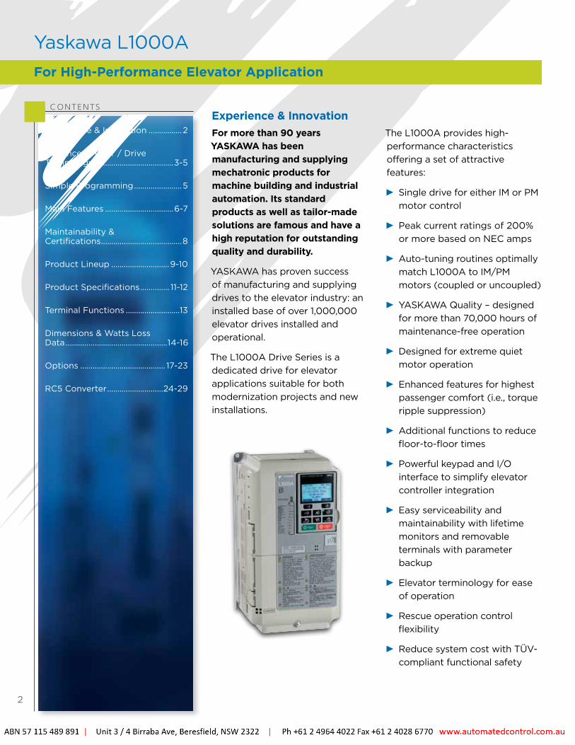
CONTENTSExperience & InnovationFor more than 90 years YASKAWA has been manufacturing and supplying mechatronic products for machine building and industrial automation. Its standard products as well as tailor-made solutions are famous and have a high reputation for outstanding quality and durability.
YASKAWA has proven success of manufacturing and supplying drives to the elevator industry: an installed base of over 1,000,000 elevator drives installed and operational.
The L1000A Drive Series is a dedicated drive for elevator applications suitable for both modernization projects and new installations.
The L1000A provides high-performance characteristics offering a set of attractive features:
Single drive for either IM or PM motor control
Peak current ratings of 200% or more based on NEC amps
Auto-tuning routines optimally match L1000A to IM/PM motors (coupled or uncoupled)
YASKAWA Quality – designed for more than 70,000 hours of maintenance-free operation
Designed for extreme quiet motor operation
Enhanced features for highest passenger comfort (i.e., torque ripple suppression)
Additional functions to reduce floor-to-floor times
Powerful keypad and I/O interface to simplify elevator controller integration
Easy serviceability and maintainability with lifetime monitors and removable terminals with parameter backup
Elevator terminology for ease of operation
Rescue operation control flexibility
Reduce system cost with TÜV- compliant functional safety
Yaskawa L1000AFor High-Performance Elevator Application

3
High-performance current vector control technology for induction and PM motor operation
Single software parameter to switch between the various motor types
Perfect for a wide range of elevator applications
Control Modes PM motors (SPM/IPM motors): Closed Loop Vector for PM
Induction motors (IM): V/f control, Open-Loop Vector, Closed-Loop Vector Control
Advanced Motor / Drive Technology
Control Mode Starting Torque Speed Range Motor Encoders and Option Cards
Closed-loop vector control for IM motors: For geared and gearless induction motors
200% at 0 rpm 1:1500Incremental encoders:- Line driver- Complementary
Closed-loop vector control for PM motors: For geared and gearless permanent magnet motors
200% at 0 rpm 1:1500
Incremental encoders:- Line driver- Complementary
Absolute encoders:- EnDat 2.1/01, 2.2/01, 2.2/22 - HEIDENHAIN ERN1387/487
Open-loop vector control for IM motors: For modernization and new installations
200% at 1 Hz 1:120 Not required
V/f control for IM motors: For modernization applications, when auto-tuning is not possible (e.g., motor current is not known)
150% at 3 Hz 1:40 Not required
Powerful Torque Characteristics
Buf
fer
Elevator
MachineRoom
Shea
ve
Gea
r
Mot
or
Cont
rolle
r(w
ith L
1000
A)
GroundLevel
Buf
fer
Underground
PMMotor
Elevator
Controller(with
L1000A)
CW CW
GroundLevel
Buf
fer
Buf
fer
Underground
MachineRoom
With IM Motor With PM Motor
4
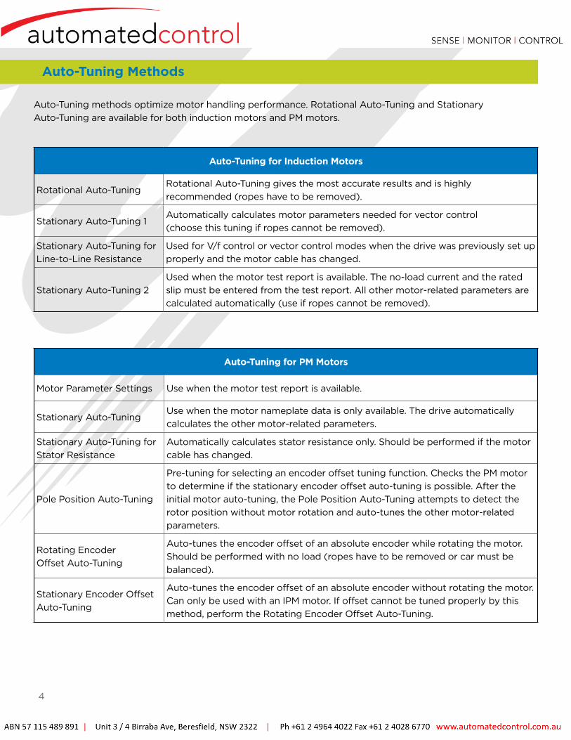
Auto-Tuning Methods
Auto-Tuning methods optimize motor handling performance. Rotational Auto-Tuning and Stationary Auto-Tuning are available for both induction motors and PM motors.
Auto-Tuning for Induction Motors
Rotational Auto-TuningRotational Auto-Tuning gives the most accurate results and is highly recommended (ropes have to be removed).
Stationary Auto-Tuning 1Automatically calculates motor parameters needed for vector control (choose this tuning if ropes cannot be removed).
Stationary Auto-Tuning for Line-to-Line Resistance
Used for V/f control or vector control modes when the drive was previously set up properly and the motor cable has changed.
Stationary Auto-Tuning 2Used when the motor test report is available. The no-load current and the rated slip must be entered from the test report. All other motor-related parameters are calculated automatically (use if ropes cannot be removed).
Auto-Tuning for PM Motors
Motor Parameter Settings Use when the motor test report is available.
Stationary Auto-TuningUse when the motor nameplate data is only available. The drive automatically calculates the other motor-related parameters.
Stationary Auto-Tuning for Stator Resistance
Automatically calculates stator resistance only. Should be performed if the motor cable has changed.
Pole Position Auto-Tuning
Pre-tuning for selecting an encoder offset tuning function. Checks the PM motor to determine if the stationary encoder offset auto-tuning is possible. After the initial motor auto-tuning, the Pole Position Auto-Tuning attempts to detect the rotor position without motor rotation and auto-tunes the other motor-related parameters.
Rotating Encoder Offset Auto-Tuning
Auto-tunes the encoder offset of an absolute encoder while rotating the motor. Should be performed with no load (ropes have to be removed or car must be balanced).
Stationary Encoder Offset Auto-Tuning
Auto-tunes the encoder offset of an absolute encoder without rotating the motor. Can only be used with an IPM motor. If offset cannot be tuned properly by this method, perform the Rotating Encoder Offset Auto-Tuning.
5
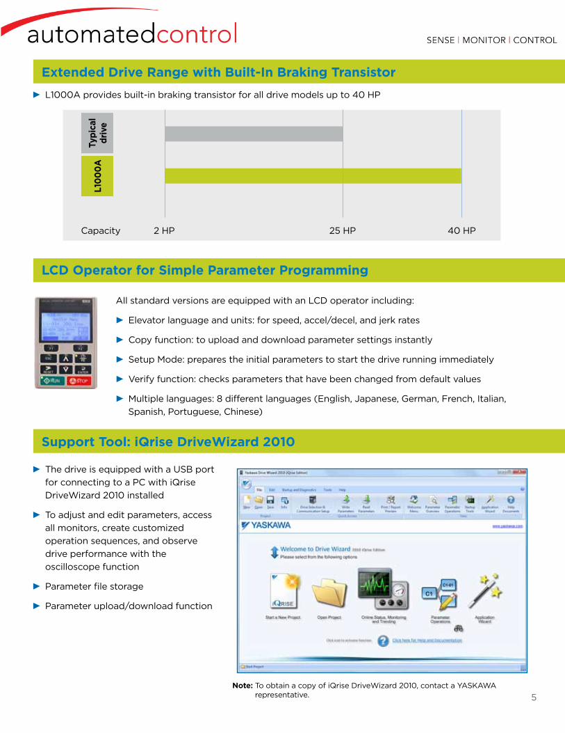
Capacity 2 HP 25 HP 40 HP
L10
00
ATy
pica
l dr
ive
L1000A provides built-in braking transistor for all drive models up to 40 HP
Extended Drive Range with Built-In Braking Transistor
Support Tool: iQrise DriveWizard 2010
The drive is equipped with a USB port for connecting to a PC with iQrise DriveWizard 2010 installed
To adjust and edit parameters, access all monitors, create customized operation sequences, and observe drive performance with the oscilloscope function
Parameter file storage
Parameter upload/download function
Note: To obtain a copy of iQrise DriveWizard 2010, contact a YASKAWA representative.
All standard versions are equipped with an LCD operator including:
Elevator language and units: for speed, accel/decel, and jerk rates
Copy function: to upload and download parameter settings instantly
Setup Mode: prepares the initial parameters to start the drive running immediately
Verify function: checks parameters that have been changed from default values
Multiple languages: 8 different languages (English, Japanese, German, French, Italian, Spanish, Portuguese, Chinese)
LCD Operator for Simple Parameter Programming
6
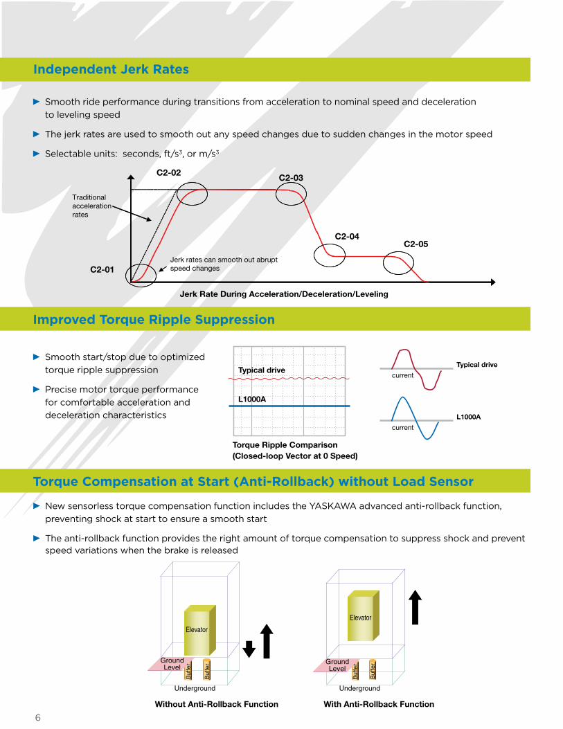
Improved Torque Ripple Suppression
Torque Compensation at Start (Anti-Rollback) without Load Sensor
Smooth start/stop due to optimized torque ripple suppression
Precise motor torque performance for comfortable acceleration and deceleration characteristics
Torque Ripple Comparison (Closed-loop Vector at 0 Speed)
Typical drive
L1000A
Typical drive
current
current
L1000A
New sensorless torque compensation function includes the YASKAWA advanced anti-rollback function, preventing shock at start to ensure a smooth start
The anti-rollback function provides the right amount of torque compensation to suppress shock and prevent speed variations when the brake is released
Smooth ride performance during transitions from acceleration to nominal speed and deceleration to leveling speed
The jerk rates are used to smooth out any speed changes due to sudden changes in the motor speed
Selectable units: seconds, ft/s3, or m/s3
C2-01
C2-02C2-03
C2-04C2-05
Jerk rates can smooth out abrupt speed changes
Traditional acceleration rates
Jerk Rate During Acceleration/Deceleration/Leveling
Independent Jerk Rates
Elevator
GroundLevel
Buf
fer
Underground
Elevator
Buf
fer Ground
Level
Buf
fer
Underground
Buf
fer
Jerk Rate During Acceleration/Deceleration/Leveling
Without Anti-Rollback Function With Anti-Rollback Function
7
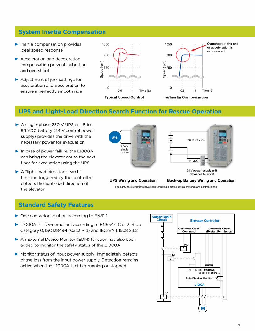
System Inertia Compensation
Inertia compensation provides ideal speed response
Acceleration and deceleration compensation prevents vibration and overshoot
Adjustment of jerk settings for acceleration and deceleration to ensure a perfectly smooth ride
1050
900
750
00.5 1 Time (S)
Sp
eed
(rp
m)
Typical Speed Control
1050
900
750
00.5 1 Time (S)
Sp
eed
(rp
m)
w/Inertia Compensation
Overshoot at the end of acceleration is suppressed
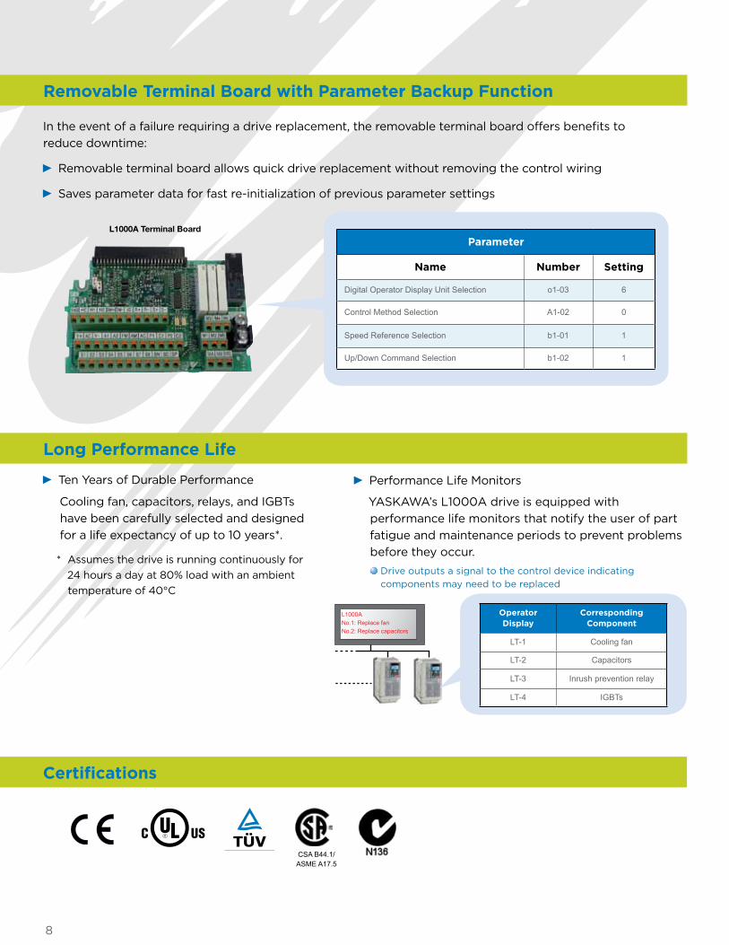
A single-phase 230 V UPS or 48 to 96 VDC battery (24 V control power supply) provides the drive with the necessary power for evacuation
In case of power failure, the L1000A can bring the elevator car to the next floor for evacuation using the UPS
A “light-load direction search” function triggered by the controller detects the light-load direction of the elevator
For clarity, the illustrations have been simplified, omitting several switches and control signals.
UPS Wiring and Operation Back-up Battery Wiring and Operation
230 Vsingle phase
48 to 96 VDC
24 VDC
UPS
24 V power supply unit(attaches to drive)
UPS and Light-Load Direction Search Function for Rescue Operation
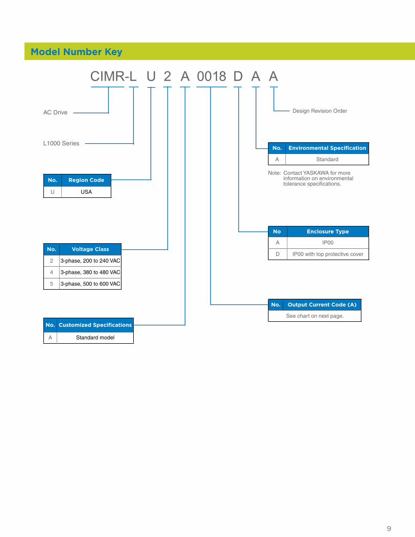
Standard Safety Features
M
Elevator ControllerSafety Chain
Circuit
L1000A
KD1
H1 H2 HC
Contactor Close Command
Contactor Check (Restart Permission)
Up/DownSpeed selection; …
Safe Disable Monitor
K1
K2
One contactor solution according to EN81-1
L1000A is TÜV-compliant according to EN954-1 Cat. 3, Stop Category 0, ISO13849-1 (Cat.3 Pld) and IEC/EN 61508 SIL2
An External Device Monitor (EDM) function has also been added to monitor the safety status of the L1000A
Monitor status of input power supply: Immediately detects phase loss from the input power supply. Detection remains active when the L1000A is either running or stopped.
8
Removable Terminal Board with Parameter Backup Function
In the event of a failure requiring a drive replacement, the removable terminal board offers benefits to reduce downtime:
Removable terminal board allows quick drive replacement without removing the control wiring
Saves parameter data for fast re-initialization of previous parameter settings
Parameter
Name Number Setting
Digital Operator Display Unit Selection o1-03 6
Control Method Selection A1-02 0
Speed Reference Selection b1-01 1
Up/Down Command Selection b1-02 1
L1000A Terminal Board
Ten Years of Durable Performance Performance Life Monitors
Cooling fan, capacitors, relays, and IGBTs have been carefully selected and designed for a life expectancy of up to 10 years*.
* Assumes the drive is running continuously for 24 hours a day at 80% load with an ambient temperature of 40°C
YASKAWA’s L1000A drive is equipped with performance life monitors that notify the user of part fatigue and maintenance periods to prevent problems before they occur.
L1000ANo.1: Replace fanNo.2: Replace capacitors
Operator Display
Corresponding Component
LT-1 Cooling fan
LT-2 Capacitors
LT-3 Inrush prevention relay
LT-4 IGBTs
Drive outputs a signal to the control device indicating components may need to be replaced
Long Performance Life
Certifications
CSA B44.1/ASME A17.5
9
CIMR- L U 2 A 0018 D A A
AC Drive
L1000 Series
Design Revision Order
No. Voltage Class
2 3-phase, 200 to 240 VAC
4 3-phase, 380 to 480 VAC
5 3-phase, 500 to 600 VAC
No. Output Current Code (A)
See chart on next page.
No. Enclosure Type
A IP00
D IP00 with top protective cover
No. Environmental Specification
A Standard
Note: Contact YASKAWA for more information on environmental tolerance specifications.
No. Customized Specifications
A Standard model
No. Region Code
U USA
Model Number Key
10
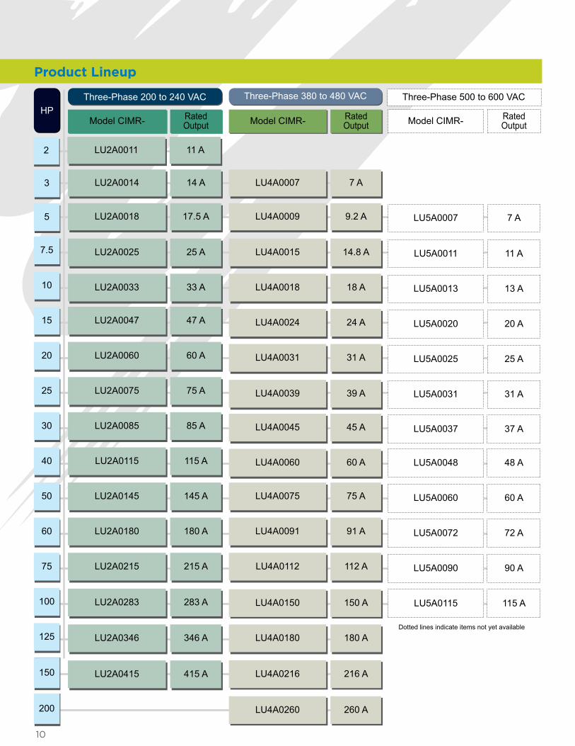
Product Lineup
HPModel CIMR- Rated
Output
Three-Phase 200 to 240 VAC Three-Phase 380 to 480 VAC Three-Phase 500 to 600 VAC
Model CIMR- RatedOutput
Rated Output
LU2A0018 17.5 A LU4A0009 9.2 A 7 A
7.5
10
15
20
25
30
40
50
60
75
100
125
150
LU2A0025 25 A
LU2A0033 33 A
LU2A0047 47 A
LU2A0060 60 A
LU2A0075 75 A
LU2A0085 85 A
LU2A0115 115 A
LU2A0145 145 A
LU2A0180 180 A
LU2A0215 215 A
LU2A0283 283 A
LU2A0346 346 A
LU2A0415 415 A
LU4A0015 14.8 A
LU4A0018 18 A
LU4A0024 24 A
LU4A0031 31 A
LU4A0039 39 A
LU4A0045 45 A
LU4A0060 60 A
LU4A0075 75 A
LU4A0091 91 A
LU4A0112 112 A
LU4A0150 150 A
LU4A0180 180 A
LU4A0216 216 A
11 A
13 A
20 A
25 A
31 A
48 A
60 A
72 A
90 A
115 A
37 A
Model CIMR-
LU5A0007
LU5A0011
LU5A0013
LU5A0020
LU5A0025
LU5A0031
LU5A0048
LU5A0060
LU5A0072
LU5A0090
LU5A0115
LU5A0037
5
200 LU4A0260 260 A
Dotted lines indicate items not yet available
LU2A0014 14 A LU4A0007 7 A3
LU2A0011 11 A2
11
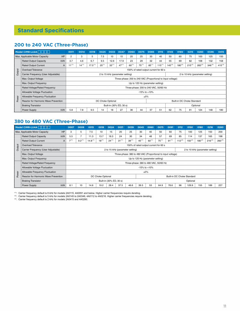
Model CIMR-LU2A 0011 0014 0018 0025 0033 0047 0060 0075 0085 0115 0145 0180 0215 0283 0346 0415
Max. Applicable Motor Capacity HP 2 3 5 7.5 10 15 20 25 30 40 50 60 75 100 125 150
Out
put
Rated Output Capacity kVA 3.7 4.6 6.7 9.5 12.6 17.9 23 29 32 44 55 69 82 108 132 158
Rated Output Current A 11<1> 14<1> 17.5<1> 25<1> 33<1> 47<1> 60<1> 75<1> 85<1> 115<1> 145<2> 180<2> 215<2> 283<2> 346<2> 415<3>
Overload Tolerance 150% of rated output current for 60 s
Carrier Frequency (User Adjustable) 2 to 15 kHz (parameter setting) 2 to 10 kHz (parameter setting)
Max. Output Voltage Three-phase: 200 to 240 VAC (Proportional to input voltage)
Max. Output Frequency Up to 120 Hz (parameter setting)
Pow
er
Rated Voltage/Rated Frequency Three-phase: 200 to 240 VAC, 50/60 Hz
Allowable Voltage Fluctuation -15% to +10%
Allowable Frequency Fluctuation ±5%
Reactor for Harmonic Wave Prevention DC Choke Optional Built-in DC Choke Standard
Braking Transistor Built-in (30% ED, 30 s) Optional
Power Supply kVA 5.8 7.8 9.5 14 18 27 36 44 37 51 62 75 91 124 148 180
200 to 240 VAC (Three-Phase)
Model CIMR-LU4A 0007 0009 0015 0018 0024 0031 0039 0045 0060 0075 0091 0112 0150 0180 0216 0260
Max. Applicable Motor Capacity HP 3 5 7.5 10 15 20 25 30 40 50 60 75 100 125 150 200
Out
put
Rated Output Capacity kVA 5.5 7 11.3 13.7 18.3 24 30 34 48 57 69 85 114 137 165 198
Rated Output Current A 7<1> 9.2<1> 14.8<1> 18<1> 24<1> 31<1> 39<1> 45<1> 60<1> 75<1> 91<1> 112<2> 150<2> 180<2> 216<2> 260<3>
Overload Tolerance 150% of rated output current for 60 s
Carrier Frequency (User Adjustable) 2 to 15 kHz (parameter setting) 2 to 10 kHz (parameter setting)
Max. Output Voltage Three-phase: 380 to 480 VAC (Proportional to input voltage)
Max. Output Frequency Up to 120 Hz (parameter setting)
Pow
er
Rated Voltage/Rated Frequency Three-phase: 380 to 480 VAC, 50/60 Hz
Allowable Voltage Fluctuation -15% to +10%
Allowable Frequency Fluctuation ±5%
Reactor for Harmonic Wave Prevention DC Choke Optional Built-in DC Choke Standard
Braking Transistor Built-in (30% ED, 30 s) Optional
Power Supply kVA 8.1 10 14.6 19.2 28.4 37.5 46.6 39.3 53 64.9 78.6 96 129.9 155 189 227
380 to 480 VAC (Three-Phase)
Standard Specifications
<1>: Carrier frequency default is 8 kHz for models 2A0115, 4A0091 and below. Higher carrier frequencies require derating.<2>: Carrier frequency default is 5 kHz for models 2A0145 to 2A0346, 4A0112 to 4A0216. Higher carrier frequencies require derating.<3>: Carrier frequency default is 2 kHz for models 2A0415 and 4A0260.
12
Item Specifications
Con
trol
Cha
ract
eris
tics
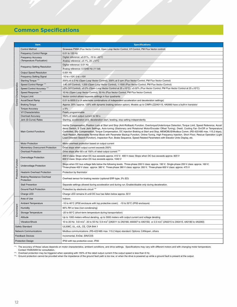
Control Method Sinewave PWM (Flux Vector Control, Open Loop Vector Control, V/f Control, PM FIux Vector control)
Frequency Control Range 0.01 to 120 Hz
Frequency Accuracy (Temperature Fluctuation)
Digital reference: ±0.01%, -10 to +40°C
Analog reference: ±0.1%, 25 ±10°C
Frequency Setting ResolutionDigital reference: 0.01 Hz
Analog reference: 0.03/60 Hz (11 bit)
Output Speed Resolution 0.001 Hz
Frequency Setting Signal -10 to +10V, 0 to +10V
Starting Torque <1> 200% at 0.3 Hz (Open Loop Vector Control), 200% at 0 rpm (Flux Vector Control, PM Flux Vector Control)
Speed Control Range <1> 1:40 (V/f Control), 1:200 (Open Loop Vector Control), 1:1500 (Flux Vector Control, PM Flux Vector Control)
Speed Control Accuracy <1> ±3% (V/f Control), ±0.2% (Open Loop Vector Control at 25 ±10°C), ±0.02% (Flux Vector Control, PM Flux Vector Control at 25 ±10°C)
Speed Response <1> 10 Hz (Open Loop Vector Control), 50 Hz (Flux Vector Control, PM Flux Vector Control)
Torque Limit Vector control allows separate settings in four quadrants
Accel/Decel Ramp 0.01 to 6000.0 s (4 selectable combinations of independent acceleration and deceleration settings)
Braking Torque Approx. 20% (approx. 125% with dynamic braking resistor option), Models up to CIMR-Lo2A0115, 4A0060 have a built-in transistor
Torque Accuracy ± 5%
V/f Characteristics Freely programmable
Overload Accuracy 150% of rated output current for 60 s
Jerk (S-Curve) Rates Starting, acceleration end, deceleration start, leveling, stop setting independently
Main Control Functions
Inertia Compensation, Position Lock at Start and Stop (Anti-Rollback) Function, Overtorque/Undertorque Detection, Torque Limit, Speed Reference, Accel/decel Switch, 5 Zone Jerk Settings, Auto-tuning (Stationary and Rotational Motor/Encoder Offset Tuning), Dwell, Cooling Fan On/Off or Temperature Controlled, Slip Compensation, Torque Compensation, DC Injection Braking at Start and Stop, MEMOBUS/Modbus Comm. (RS-422/485 max. 115.2 kbps), Fault Restart, Removable Terminal Block with Parameter Backup Function, Online Tuning, High Frequency Injection, Short Floor, Rescue Operation (Light Load Direction Search Function), Inspection Run, Brake Sequence, Speed Related Parameters with Elevator Units Display, etc.
Pro
tect
ion
Fun
ctio
n
Motor Protection Motor overheat protection based on output current
Momentary Overcurrent Protection Drive stops when output current exceeds 200%
Overload Protection Drive stops after 60 s at 150% of rated output current <2>
Overvoltage Protection200 V class: Stops when DC bus exceeds approx. 410 V; 400 V class: Stops when DC bus exceeds approx. 820 V 600 V class: Stops when DC bus exceeds approx. 1040 V
Undervoltage ProtectionStops when DC bus voltage falls below the following levels: Three-phase 200 V class: approx. 190 V; Single-phase 200 V class: approx. 160 V; Three-phase 400 V class: approx. 380 V; Three-phase 380 V class: approx. 350 V; Three-phase 600 V class: approx. 475 V
Heatsink Overheat Protection Protection by thermistor
Braking Resistance Overheat Protection
Overheat sensor for braking resistor (optional ERF-type, 3% ED)
Stall Prevention Separate settings allowed during acceleration and during run. Enable/disable only during deceleration.
Ground Fault Protection Protection by electronic circuit <3>
Charge LED Charge LED remains lit until DC bus has fallen below approx. 50 V
Env
ironm
ent
Area of Use Indoors
Ambient Temperature -10 to 40°C (IP00 enclosure with top protective cover); -10 to 50°C (IP00 enclosure)
Humidity 95% RH or less (non-condensing)
Storage Temperature -20 to 60°C (short-term temperature during transportation)
Altitude Up to 1000 meters without derating, up to 3000 meters with output current and voltage derating
Vibration/Shock 10 to 20 Hz: 9.8 m/s2; 20 to 55 Hz: 5.9 m/s2 (2A0011 to 2A0180; 4A0007 to 4A0150) or 2.0 m/s2 (2A0215 to 2A0415, 4A0180 to 4A0260)
Safety Standard UL508C, UL, cUL, CE, CSA B44.1
Network Communications Modbus communications. (RS-422/485 max. 115.2 kbps) standard. Options: CANopen, others
Feedback Devices Incremental, EnDat, SIN/COS
Protection Design IP00 with top protective cover, IP00
<1>: The accuracy of these values depends on motor characteristics, ambient conditions, and drive settings. Specifications may vary with different motors and with changing motor temperature. Contact YASKAWA for consultation.
<2>: Overload protection may be triggered when operating with 150% of the rated output current if the output speed is less than 6 Hz.<3>: Ground protection cannot be provided when the impedance of the ground fault path is too low, or when the drive is powered up while a ground fault is present at the output.
Common Specifications
13
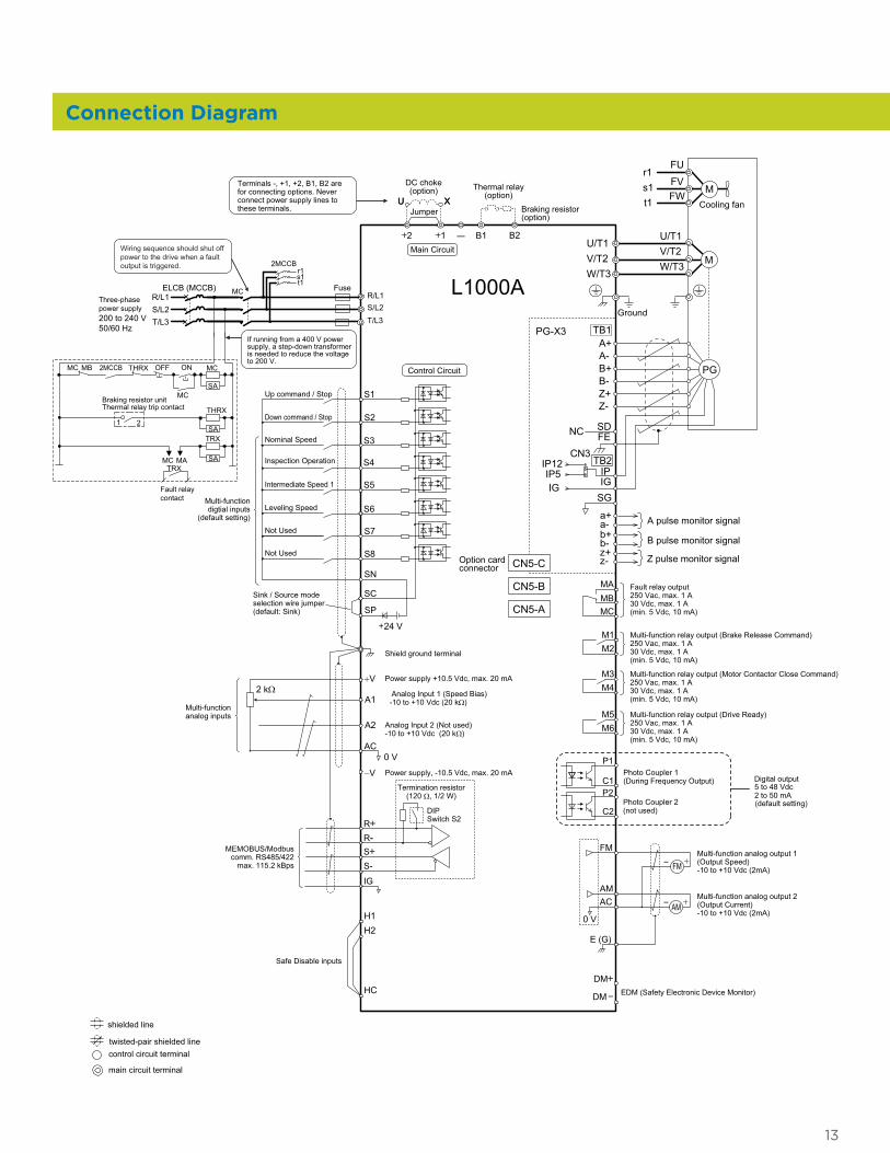
Connection Diagram
Shield ground terminal
++DM
DM
H1H2
HC
R/L1S/L2T/L3
Fuse
MC 2MCCBMB ONOFFTHRX
SA
1 2
TRX
MC MATRX
Fault relaycontact
Braking resistor unitThermal relay trip contact
MC
MC
SA
SA
THRX
ELCB (MCCB)R/L1
T/L3S/L2
Three-phasepower supply200 to 240 V50/60 Hz
2MCCBr1s1t1
MC
Wiring sequence should shut off power to the drive when a fault output is triggered.
If running from a 400 V power supply, a step-down transformer is needed to reduce the voltage to 200 V.
P1
P2C1
C2
Photo Coupler 1(During Frequency Output)
Photo Coupler 2(not used)
Digital output5 to 48 Vdc2 to 50 mA(default setting)
+
-+
++
Terminals -, +1, +2, B1, B2 are for connecting options. Never connect power supply lines to these terminals.
DC choke(option)
U XThermal relay
(option)
+
-+
++
+
U X
S1
S2
S3
S4
S5
S6
S7
A1
A2
0 VAC
RRSS-
IG
L1000A
B112 B2
2 kΩ
S8
SC
0 V
FM
AMAC
E (G)
—
+24 V
+V
MA
M1M2
MBMC
Jumper Braking resistor(option)
Up command / Stop
Nominal Speed
Inspection Operation
Intermediate Speed 1
Not Used
Multi-function digtial inputs
(default setting)
Sink / Source mode selection wire jumper(default: Sink)
Multi-function analog inputs
Power supply +10.5 Vdc, max. 20 mA
Analog Input 1 (Speed Bias)-10 to +10 Vdc (20 kΩ)
Analog Input 2 (Not used)-10 to +10 Vdc (20 kΩ)
−V Power supply, -10.5 Vdc, max. 20 mA
MEMOBUS/Modbus comm. RS485/422
max. 115.2 kBps
Termination resistor(120 Ω, 1/2 W)
DIP Switch S2
Fault relay output250 Vac, max. 1 A30 Vdc, max. 1 A(min. 5 Vdc, 10 mA)
Multi-function relay output (Brake Release Command)250 Vac, max. 1 A30 Vdc, max. 1 A(min. 5 Vdc, 10 mA)
Multi-function analog output 1(Output Speed)-10 to +10 Vdc (2mA)
Multi-function analog output 2(Output Current)-10 to +10 Vdc (2mA)
Main Circuit
Control Circuit
shielded line
twisted-pair shielded line
main circuit terminal
control circuit terminal
M3M4
Multi-function relay output (Motor Contactor Close Command)250 Vac, max. 1 A30 Vdc, max. 1 A(min. 5 Vdc, 10 mA)
M5M6
Multi-function relay output (Drive Ready)250 Vac, max. 1 A30 Vdc, max. 1 A(min. 5 Vdc, 10 mA)
SP
SN
FM
+AM
Down command / Stop
Leveling Speed
Not Used
FESDNC
a+a-
b-
z-
b+
z+
IPIG
IP12IP5IG
SG
TB2
A pulse monitor signal
B pulse monitor signal
Z pulse monitor signal
CN3
PG
A+A-
B-
Z-
B+
Z+
TB1PG-X3
CN5-C
CN5-B
CN5-A
Option cardconnector
MU/T1V/T2W/T3
Ground
Cooling fan
Mr1s1t1
FU
FVFW
EDM (Safety Electronic Device Monitor)
Safe Disable inputs
U/T1V/T2W/T3
–
–
–
W1
1.5
HH1
H2W
DD1
t1
Figure 1
4-d
Figure 2
W1 4-d
H1 H
H2
Max 0.4Max 0.4 W
t2
t1D1D
14
Model CIMR-LUo
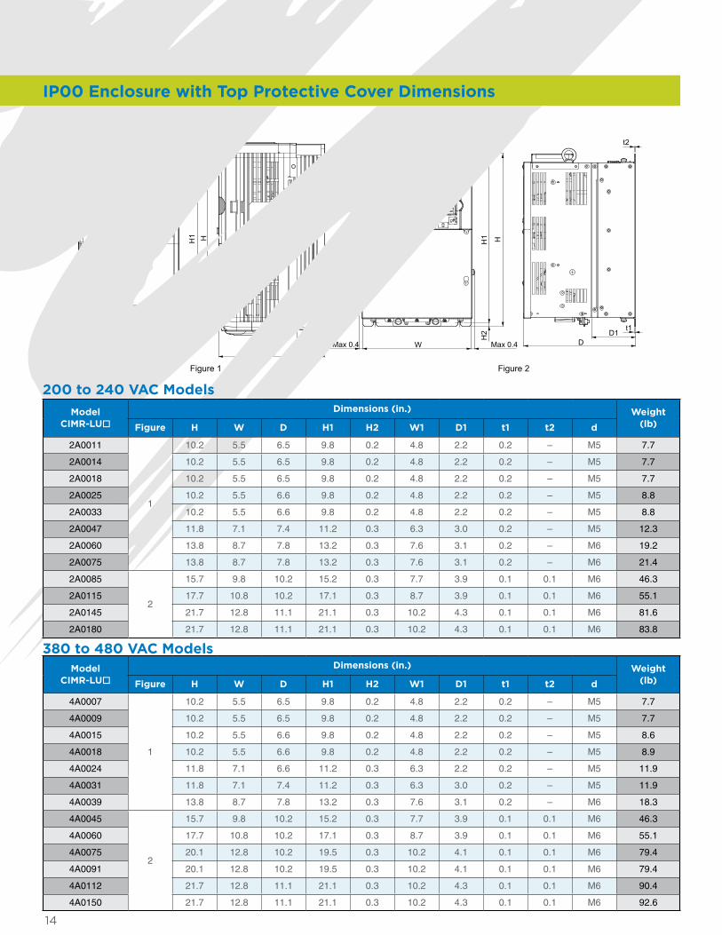
Dimensions (in.) Weight (lb)Figure H W D H1 H2 W1 D1 t1 t2 d
2A0011
1
10.2 5.5 6.5 9.8 0.2 4.8 2.2 0.2 – M5 7.7
2A0014 10.2 5.5 6.5 9.8 0.2 4.8 2.2 0.2 – M5 7.7
2A0018 10.2 5.5 6.5 9.8 0.2 4.8 2.2 0.2 – M5 7.7
2A0025 10.2 5.5 6.6 9.8 0.2 4.8 2.2 0.2 – M5 8.8
2A0033 10.2 5.5 6.6 9.8 0.2 4.8 2.2 0.2 – M5 8.8
2A0047 11.8 7.1 7.4 11.2 0.3 6.3 3.0 0.2 – M5 12.3
2A0060 13.8 8.7 7.8 13.2 0.3 7.6 3.1 0.2 – M6 19.2
2A0075 13.8 8.7 7.8 13.2 0.3 7.6 3.1 0.2 – M6 21.4
2A0085
2
15.7 9.8 10.2 15.2 0.3 7.7 3.9 0.1 0.1 M6 46.3
2A0115 17.7 10.8 10.2 17.1 0.3 8.7 3.9 0.1 0.1 M6 55.1
2A0145 21.7 12.8 11.1 21.1 0.3 10.2 4.3 0.1 0.1 M6 81.6
2A0180 21.7 12.8 11.1 21.1 0.3 10.2 4.3 0.1 0.1 M6 83.8
200 to 240 VAC Models
Model CIMR-LUo
Dimensions (in.) Weight (lb)Figure H W D H1 H2 W1 D1 t1 t2 d
4A0007
1
10.2 5.5 6.5 9.8 0.2 4.8 2.2 0.2 – M5 7.7
4A0009 10.2 5.5 6.5 9.8 0.2 4.8 2.2 0.2 – M5 7.7
4A0015 10.2 5.5 6.6 9.8 0.2 4.8 2.2 0.2 – M5 8.6
4A0018 10.2 5.5 6.6 9.8 0.2 4.8 2.2 0.2 – M5 8.9
4A0024 11.8 7.1 6.6 11.2 0.3 6.3 2.2 0.2 – M5 11.9
4A0031 11.8 7.1 7.4 11.2 0.3 6.3 3.0 0.2 – M5 11.9
4A0039 13.8 8.7 7.8 13.2 0.3 7.6 3.1 0.2 – M6 18.3
4A0045
2
15.7 9.8 10.2 15.2 0.3 7.7 3.9 0.1 0.1 M6 46.3
4A0060 17.7 10.8 10.2 17.1 0.3 8.7 3.9 0.1 0.1 M6 55.1
4A0075 20.1 12.8 10.2 19.5 0.3 10.2 4.1 0.1 0.1 M6 79.4
4A0091 20.1 12.8 10.2 19.5 0.3 10.2 4.1 0.1 0.1 M6 79.4
4A0112 21.7 12.8 11.1 21.1 0.3 10.2 4.3 0.1 0.1 M6 90.4
4A0150 21.7 12.8 11.1 21.1 0.3 10.2 4.3 0.1 0.1 M6 92.6
380 to 480 VAC Models
IP00 Enclosure with Top Protective Cover Dimensions

15
IP00 Enclosure Dimensions
4-d
Wmax. 0.4 max. 0.4
t1
DH
1 H
W1
H2
t2
D1
Figure 1
Model CIMR-LUo
Dimensions (in.)Weight
(lb)Figure H W D H1 H2 W1 D1 t1 t2 d
2A0215
1
27.8 17.7 13.0 26.8 0.5 12.8 5.1 0.1 0.1 M10 167.6
2A0283 27.8 17.7 13.0 26.8 0.5 12.8 5.1 0.1 0.1 M10 176.4
2A0346 31.5 19.7 13.8 30.4 0.5 14.6 5.1 0.2 0.2 M12 216.1
2A0415 31.5 19.7 13.8 30.4 0.5 14.6 5.1 0.2 0.2 M12 218.3
Model CIMR-LUo
Dimensions (in.)Weight
(lb)Figure H W D H1 H2 W1 D1 t1 t2 d
4A0180
1
27.8 17.7 13.0 26.8 0.5 12.8 5.1 0.1 0.1 M10 174.2
4A0216 31.5 19.7 13.8 30.4 0.5 14.6 5.1 0.2 0.2 M12 211.6
4A0260 31.5 19.7 13.8 30.4 0.5 14.6 5.1 0.2 0.2 M12 224.9
380 to 480 VAC Models
200 to 240 VAC Models
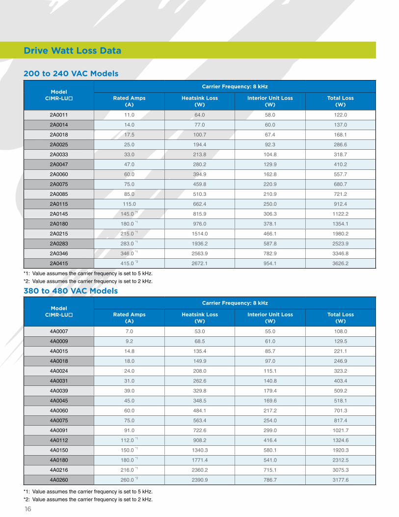
16
*1: Value assumes the carrier frequency is set to 5 kHz.
*2: Value assumes the carrier frequency is set to 2 kHz.
200 to 240 VAC Models
Model CIMR-LUo
Carrier Frequency: 8 kHz
Rated Amps (A)
Heatsink Loss (W)
Interior Unit Loss (W)
Total Loss (W)
2A0011 11.0 64.0 58.0 122.0
2A0014 14.0 77.0 60.0 137.0
2A0018 17.5 100.7 67.4 168.1
2A0025 25.0 194.4 92.3 286.6
2A0033 33.0 213.8 104.8 318.7
2A0047 47.0 280.2 129.9 410.2
2A0060 60.0 394.9 162.8 557.7
2A0075 75.0 459.8 220.9 680.7
2A0085 85.0 510.3 210.9 721.2
2A0115 115.0 662.4 250.0 912.4
2A0145 145.0 *1 815.9 306.3 1122.2
2A0180 180.0 *1 976.0 378.1 1354.1
2A0215 215.0 *1 1514.0 466.1 1980.2
2A0283 283.0 *1 1936.2 587.8 2523.9
2A0346 346.0 *1 2563.9 782.9 3346.8
2A0415 415.0 *2 2672.1 954.1 3626.2
*1: Value assumes the carrier frequency is set to 5 kHz.
*2: Value assumes the carrier frequency is set to 2 kHz.
380 to 480 VAC Models
Model CIMR-LUo
Carrier Frequency: 8 kHz
Rated Amps (A)
Heatsink Loss (W)
Interior Unit Loss (W)
Total Loss (W)
4A0007 7.0 53.0 55.0 108.0
4A0009 9.2 68.5 61.0 129.5
4A0015 14.8 135.4 85.7 221.1
4A0018 18.0 149.9 97.0 246.9
4A0024 24.0 208.0 115.1 323.2
4A0031 31.0 262.6 140.8 403.4
4A0039 39.0 329.8 179.4 509.2
4A0045 45.0 348.5 169.6 518.1
4A0060 60.0 484.1 217.2 701.3
4A0075 75.0 563.4 254.0 817.4
4A0091 91.0 722.6 299.0 1021.7
4A0112 112.0 *1 908.2 416.4 1324.6
4A0150 150.0 *1 1340.3 580.1 1920.3
4A0180 180.0 *1 1771.4 541.0 2312.5
4A0216 216.0 *1 2360.2 715.1 3075.3
4A0260 260.0 *2 2390.9 786.7 3177.6
Drive Watt Loss Data
17
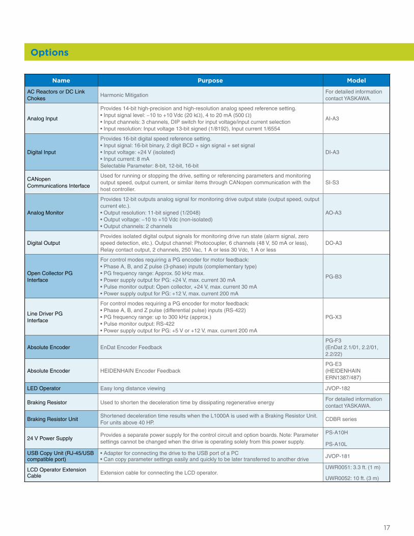
Options
Name Purpose Model
AC Reactors or DC Link Chokes
Harmonic MitigationFor detailed information contact YASKAWA.
Analog Input
Provides 14-bit high-precision and high-resolution analog speed reference setting.• Input signal level: −10 to +10 Vdc (20 kΩ), 4 to 20 mA (500 Ω)• Input channels: 3 channels, DIP switch for input voltage/input current selection• Input resolution: Input voltage 13-bit signed (1/8192), Input current 1/6554
AI-A3
Digital Input
Provides 16-bit digital speed reference setting.• Input signal: 16-bit binary, 2 digit BCD + sign signal + set signal• Input voltage: +24 V (isolated)• Input current: 8 mASelectable Parameter: 8-bit, 12-bit, 16-bit
DI-A3
CANopen Communications Interface
Used for running or stopping the drive, setting or referencing parameters and monitoring output speed, output current, or similar items through CANopen communication with the host controller.
SI-S3
Analog Monitor
Provides 12-bit outputs analog signal for monitoring drive output state (output speed, output current etc.).• Output resolution: 11-bit signed (1/2048)• Output voltage: −10 to +10 Vdc (non-isolated)• Output channels: 2 channels
AO-A3
Digital OutputProvides isolated digital output signals for monitoring drive run state (alarm signal, zero speed detection, etc.). Output channel: Photocoupler, 6 channels (48 V, 50 mA or less), Relay contact output, 2 channels, 250 Vac, 1 A or less 30 Vdc, 1 A or less
DO-A3
Open Collector PG Interface
For control modes requiring a PG encoder for motor feedback:• Phase A, B, and Z pulse (3-phase) inputs (complementary type)• PG frequency range: Approx. 50 kHz max.• Power supply output for PG: +24 V, max. current 30 mA• Pulse monitor output: Open collector, +24 V, max. current 30 mA• Power supply output for PG: +12 V, max. current 200 mA
PG-B3
Line Driver PG Interface
For control modes requiring a PG encoder for motor feedback:• Phase A, B, and Z pulse (differential pulse) inputs (RS-422)• PG frequency range: up to 300 kHz (approx.)• Pulse monitor output: RS-422• Power supply output for PG: +5 V or +12 V, max. current 200 mA
PG-X3
Absolute Encoder EnDat Encoder FeedbackPG-F3 (EnDat 2.1/01, 2.2/01, 2.2/22)
Absolute Encoder HEIDENHAIN Encoder FeedbackPG-E3 (HEIDENHAIN ERN1387/487)
LED Operator Easy long distance viewing JVOP-182
Braking Resistor Used to shorten the deceleration time by dissipating regenerative energy For detailed information contact YASKAWA.
Braking Resistor UnitShortened deceleration time results when the L1000A is used with a Braking Resistor Unit. For units above 40 HP.
CDBR series
24 V Power SupplyProvides a separate power supply for the control circuit and option boards. Note: Parameter settings cannot be changed when the drive is operating solely from this power supply.
PS-A10H
PS-A10L
USB Copy Unit (RJ-45/USB compatible port)
• Adapter for connecting the drive to the USB port of a PC • Can copy parameter settings easily and quickly to be later transferred to another drive JVOP-181
LCD Operator Extension Cable Extension cable for connecting the LCD operator.
UWR0051: 3.3 ft. (1 m)
UWR0052: 10 ft. (3 m)
18
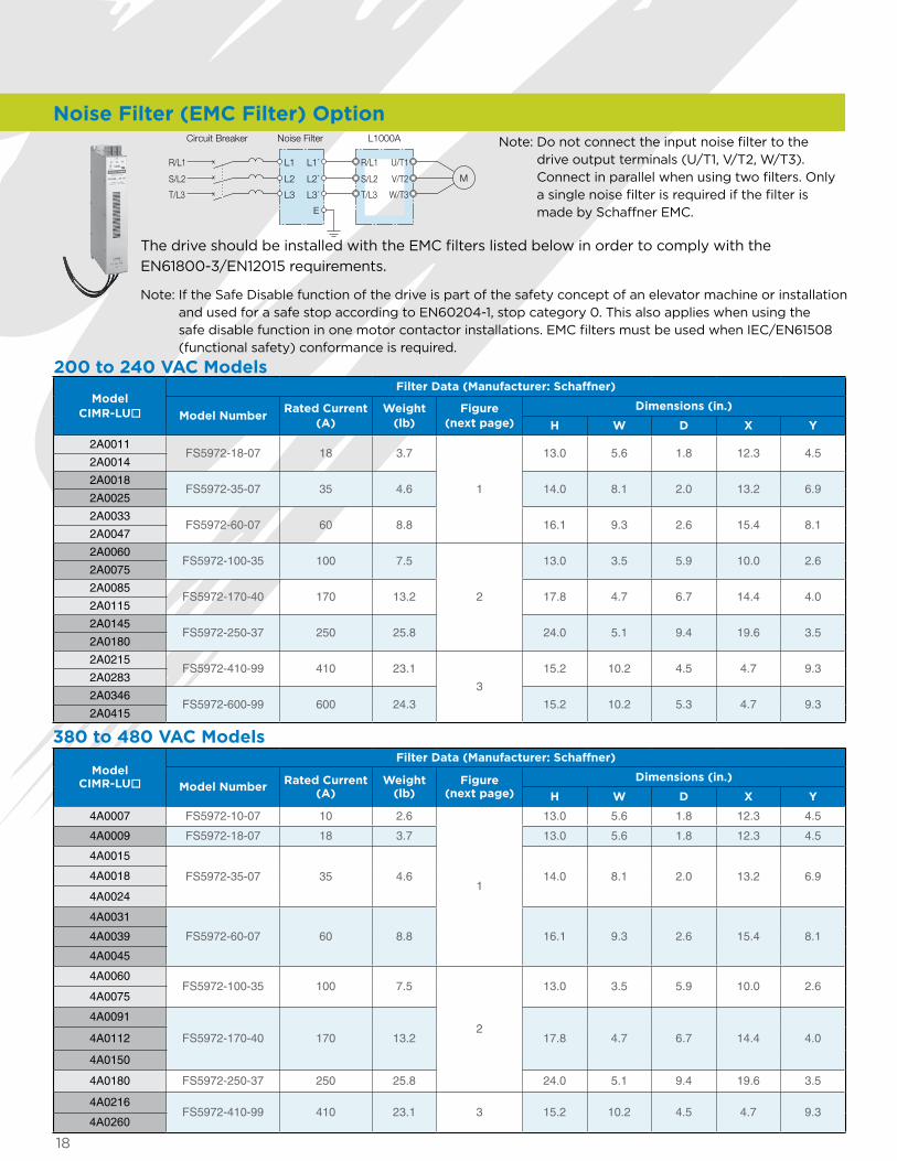
Noise Filter L1000A
M
R/L1
S/L2
T/L3
R/L1
S/L2
T/L3
L1
L2
U/T1
V/T2
W/T3
L1´
L2´
E
L3 L3´
Circuit Breaker Note: Do not connect the input noise filter to the drive output terminals (U/T1, V/T2, W/T3). Connect in parallel when using two filters. Only a single noise filter is required if the filter is made by Schaffner EMC.
The drive should be installed with the EMC filters listed below in order to comply with the EN61800-3/EN12015 requirements.
Note: If the Safe Disable function of the drive is part of the safety concept of an elevator machine or installation and used for a safe stop according to EN60204-1, stop category 0. This also applies when using the safe disable function in one motor contactor installations. EMC filters must be used when IEC/EN61508 (functional safety) conformance is required.
Model CIMR-LUo
Filter Data (Manufacturer: Schaffner)
Model NumberRated Current
(A)Weight
(lb)Figure
(next page)Dimensions (in.)
H W D X Y
2A0011FS5972-18-07 18 3.7
1
13.0 5.6 1.8 12.3 4.52A0014
2A0018FS5972-35-07 35 4.6 14.0 8.1 2.0 13.2 6.9
2A0025
2A0033FS5972-60-07 60 8.8 16.1 9.3 2.6 15.4 8.1
2A0047
2A0060FS5972-100-35 100 7.5
2
13.0 3.5 5.9 10.0 2.62A0075
2A0085FS5972-170-40 170 13.2 17.8 4.7 6.7 14.4 4.0
2A0115
2A0145FS5972-250-37 250 25.8 24.0 5.1 9.4 19.6 3.5
2A0180
2A0215FS5972-410-99 410 23.1
3
15.2 10.2 4.5 4.7 9.32A0283
2A0346FS5972-600-99 600 24.3 15.2 10.2 5.3 4.7 9.3
2A0415
Model CIMR-LUo
Filter Data (Manufacturer: Schaffner)
Model Number Rated Current (A)
Weight (lb)
Figure (next page)
Dimensions (in.)
H W D X Y
4A0007 FS5972-10-07 10 2.6
1
13.0 5.6 1.8 12.3 4.5
4A0009 FS5972-18-07 18 3.7 13.0 5.6 1.8 12.3 4.5
4A0015
FS5972-35-07 35 4.6 14.0 8.1 2.0 13.2 6.94A0018
4A0024
4A0031
FS5972-60-07 60 8.8 16.1 9.3 2.6 15.4 8.14A0039
4A0045
4A0060FS5972-100-35 100 7.5
2
13.0 3.5 5.9 10.0 2.64A0075
4A0091
FS5972-170-40 170 13.2 17.8 4.7 6.7 14.4 4.04A0112
4A0150
4A0180 FS5972-250-37 250 25.8 24.0 5.1 9.4 19.6 3.5
4A0216FS5972-410-99 410 23.1 3 15.2 10.2 4.5 4.7 9.3
4A0260
200 to 240 VAC Models
380 to 480 VAC Models
Noise Filter (EMC Filter) Option
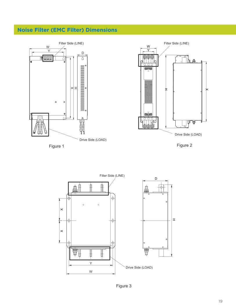
Noise Filter (EMC Filter) Dimensions
19
Drive Side (LOAD)
Filter Side (LINE)
L1 L2L2
L1 L3
L3''1L '2L
LOAD
LOAD
PERecommended torque: 26 - 30Nm / PE: 15 - 17Nm
' 2L' 1L L3'
L1
L1
L2
L2
L3
L3LINE
LINE
PE
Recommended torque: 26 - 30Nm / PE: 15 - 17Nm
Filter Side (LINE) Filter Side (LINE)
Drive Side (LOAD)Drive Side (LOAD)
XH
WY
X H
WY D
Figure 1
Figure 3
Figure 2
W
Y
H
D
XX

20
The L1000A includes a built-in braking transistor up to 40 HP (200-240 VAC and 380-480 VAC). For L1000A drives above 40 HP with braking torque requirements, a CDBR Braking Unit is available as an option. Please contact a YASKAWA representative for further information on braking resistors. The table below indicates the recommended CDBR Braking Unit and the resistor specification.
Max. Applicable Motor (HP)
L1000A Braking Unit Braking Resistor UnitMin.* Connection
Resistance (Ω)Model
CIMR-LUoModel
CDBR- Qty.Resistor
Specifications(per unit)
Qty.Braking
Torque (%)(10% ED)
3 4A0007
Built-in
390 W 150 Ω 1 150 325 4A0009 390 W 150 Ω 1 135 32
7.5 4A0015 520 W 100 Ω 1 135 3210 4A0018 780 W 75 Ω 1 130 3215 4A0024 1040 W 50 Ω 1 135 2020 4A0031 1560 W 40 Ω 1 125 2025 4A0039 4800 W 32 Ω 1 125 19.230 4A0045 4800 W 27.2 Ω 1 125 19.240 4A0060 6000 W 20 Ω 1 125 19.250 4A0075 40450D 1 9600 W 16 Ω 1 125 12.860 4A0091 40450D 1 9600 W 13.6 Ω 1 125 12.875 4A0112 40450D 2 6000 W 20 Ω 2 135 19.2
100 4A0150 40450D 2 9600 W 13.6 Ω 2 145 12.8125 4A0180 40450D 2 9600 W 13.6 Ω 2 120 12.8150 4A0216 40450D 3 6000 W 20 Ω 3 100 3.2200 4A0260 4220B 1 9600 W 13.6 Ω 4 140 3.2
Max. Applicable Motor (HP)
L1000A Braking Unit Braking Resistor UnitMin.* Connection
Resistance (Ω)Model
CIMR-LUModel
CDBR- Qty.Resistor
Specifications(per unit)
Qty.Braking
Torque (%)(10% ED)
2 2A0011
Built-in
260 W 70 Ω 1 120 163 2A0014 390 W 40 Ω 1 150 165 2A0018 390 W 40 Ω 1 125 16
7.5 2A0025 520 W 30 Ω 1 115 1610 2A0033 780 W 20 Ω 1 125 9.615 2A0047 2400 W 13.6 Ω 1 125 9.620 2A0060 3000 W 10 Ω 1 125 9.625 2A0075 3000 W 10 Ω 1 100 9.630 2A0085 4800 W 6.8 Ω 1 125 6.440 2A0115 4800 W 6.8 Ω 1 90 6.450 2A0145 20370D 1 3000 W 10 Ω 2 100 9.660 2A0180 20370D 2 4800 W 6.8 Ω 2 120 6.475 2A0215 20370D 2 4800 W 6.8 Ω 2 100 6.4
100 2A0283 2110B 1 4800 W 6.8 Ω 3 110 1.6125 2A0346 2110B 1 4800 W 6.8 Ω 4 120 1.6150 2A0415 2110B 1 4800 W 8 Ω 5 100 1.6
* The value shown for the minimum connection resistance is that for a single braking unit. Select a resistance value higher than the connectable resistance value and enough to generate the required braking torque.
CDBR Braking Unit Option
200 to 240 VAC Models
380 to 480 VAC Models
21
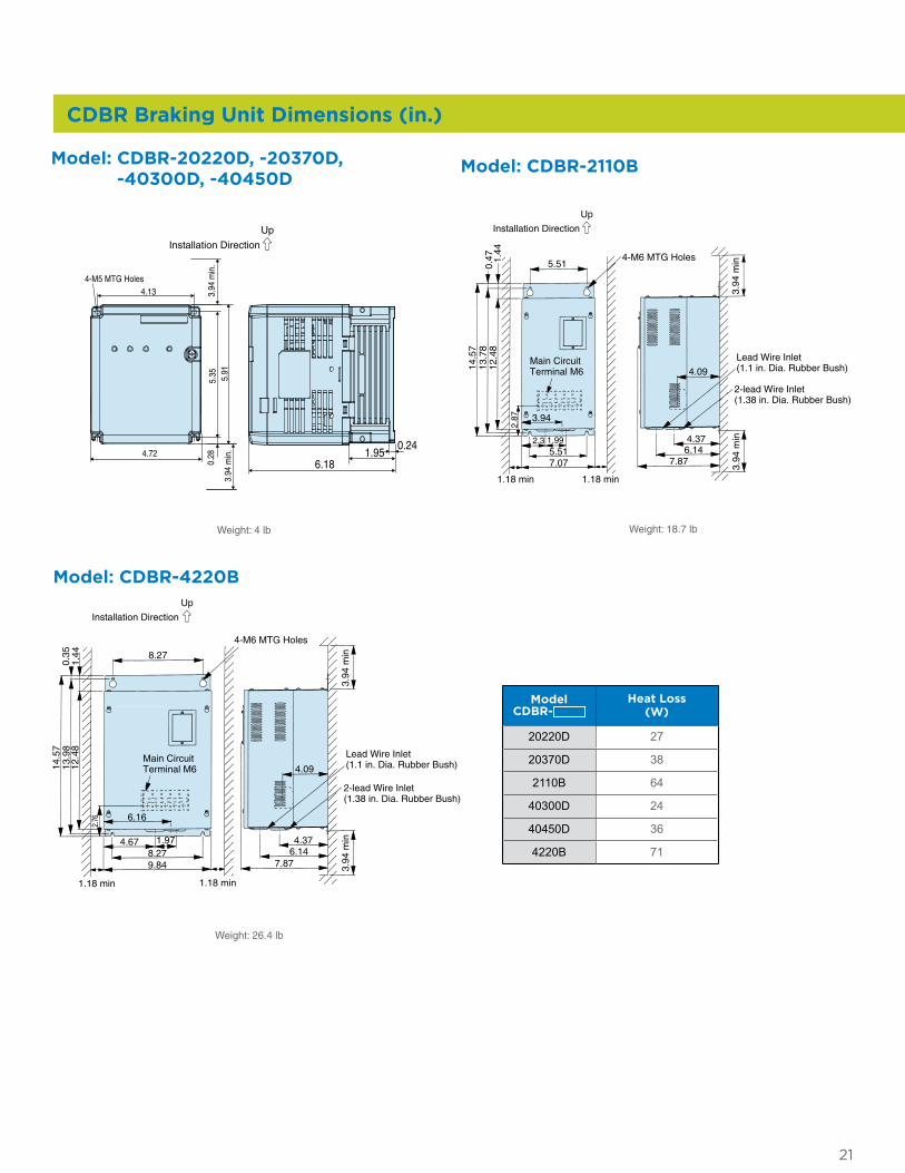
CDBR Braking Unit Dimensions (in.)
Installation Direction
Up
4.13
5.91
5.35
6.181.95
0.244.72
0.28
3.94
min
.
4-M5 MTG Holes
3.94
min
.
5.51
4.09
Lead Wire Inlet (1.1 in. Dia. Rubber Bush)
2-lead Wire Inlet (1.38 in. Dia. Rubber Bush)
4.376.14
7.87
3.94
2.3
1.18 min 1.18 min
1.995.517.07
0.47 1.
4412
.48
3.94
min
3.94
min
2.87
13.7
814
.57
Installation Direction
4-M6 MTG Holes
Main Circuit Terminal M6
Up
6.16
8.27
4.09
4.67 1.978.279.84 7.87
6.144.37
1.18 min 1.18 min
0.35
1.44
3.94
min
3.94
min
12.4
813
.98
14.5
7
2.76
4-M6 MTG Holes
Main Circuit Terminal M6
Lead Wire Inlet (1.1 in. Dia. Rubber Bush)
2-lead Wire Inlet (1.38 in. Dia. Rubber Bush)
Installation Direction
Up
Model: CDBR-20220D, -20370D, -40300D, -40450D
Model: CDBR-2110B
Model: CDBR-4220B
ModelCDBR-
Heat Loss(W)
20220D 27
20370D 38
2110B 64
40300D 24
40450D 36
4220B 71
Weight: 4 lb Weight: 18.7 lb
Weight: 26.4 lb
22
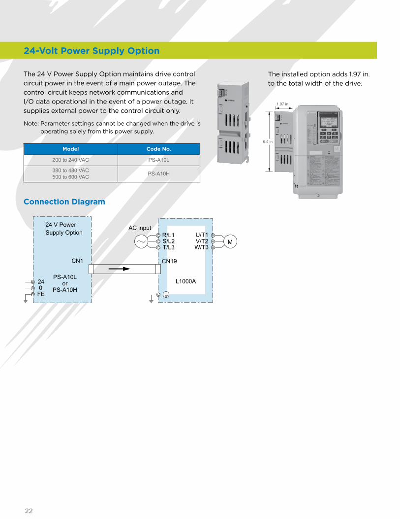
The 24 V Power Supply Option maintains drive control circuit power in the event of a main power outage. The control circuit keeps network communications and I/O data operational in the event of a power outage. It supplies external power to the control circuit only.
Note: Parameter settings cannot be changed when the drive is operating solely from this power supply.
Connection Diagram
The installed option adds 1.97 in. to the total width of the drive.
1.97 in
Model Code No.
200 to 240 VAC PS-A10L
380 to 480 VAC 500 to 600 VAC PS-A10H
R/L1
T/L3S/L2
U/T1V/T2W/T3
M
AC input
L1000A240
FE
24 V Power Supply Option
CN19CN1
PS-A10Lor
PS-A10H
24-Volt Power Supply Option
6.4 in
23
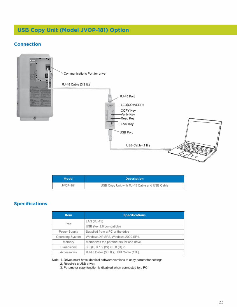
USB Copy Unit (Model JVOP-181) Option
RJ-45 Cable (3.3 ft.)
LED(COM/ERR)
COPY KeyVerify KeyRead Key
USB Port
USB Cable (1 ft.)
RJ-45 Port
Lock Key
Communications Port for drive
Model Description
JVOP-181 USB Copy Unit with RJ-45 Cable and USB Cable
Item Specifications
PortLAN (RJ-45)
USB (Ver.2.0 compatible)
Power Supply Supplied from a PC or the drive
Operating System Windows XP SP2, Windows 2000 SP4
Memory Memorizes the parameters for one drive.
Dimensions 3.5 (H) × 1.2 (W) × 0.8 (D) in.
Accessories RJ-45 Cable (3.3 ft.), USB Cable (1 ft.)
Specifications
Note: 1. Drives must have identical software versions to copy parameter settings. 2. Requires a USB driver. 3. Parameter copy function is disabled when connected to a PC.
Connection
24
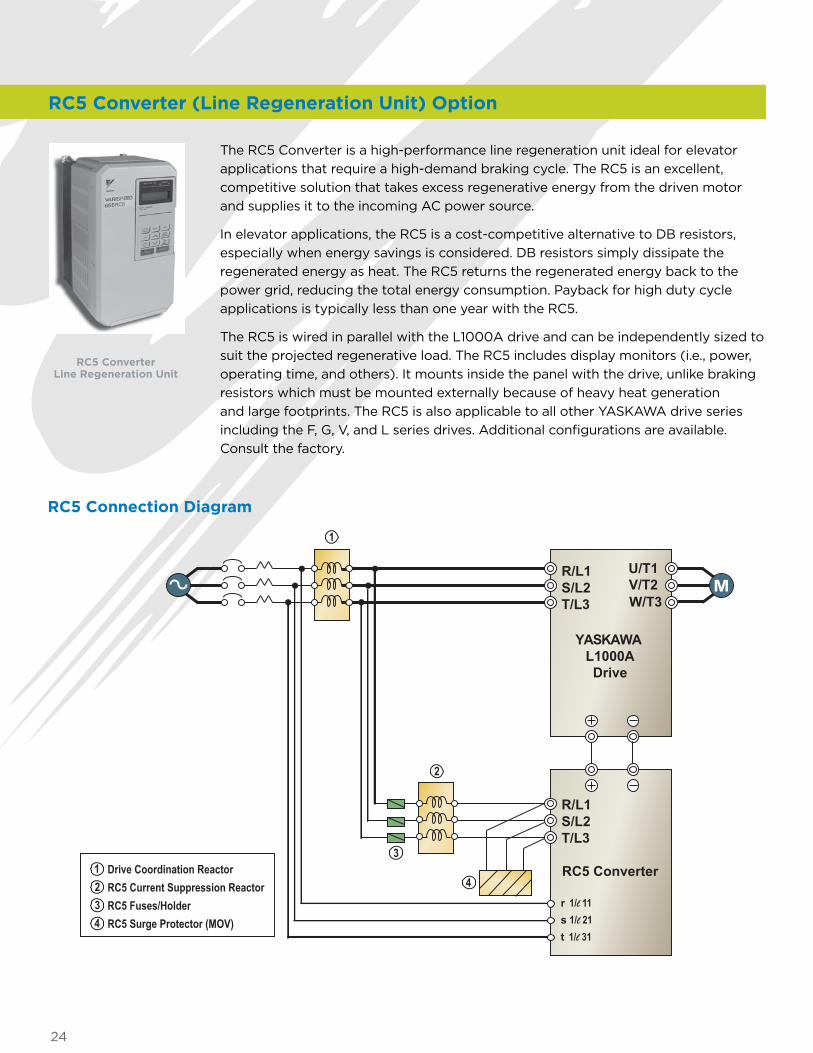
The RC5 Converter is a high-performance line regeneration unit ideal for elevator applications that require a high-demand braking cycle. The RC5 is an excellent, competitive solution that takes excess regenerative energy from the driven motor and supplies it to the incoming AC power source.
In elevator applications, the RC5 is a cost-competitive alternative to DB resistors, especially when energy savings is considered. DB resistors simply dissipate the regenerated energy as heat. The RC5 returns the regenerated energy back to the power grid, reducing the total energy consumption. Payback for high duty cycle applications is typically less than one year with the RC5.
The RC5 is wired in parallel with the L1000A drive and can be independently sized to suit the projected regenerative load. The RC5 includes display monitors (i.e., power, operating time, and others). It mounts inside the panel with the drive, unlike braking resistors which must be mounted externally because of heavy heat generation and large footprints. The RC5 is also applicable to all other YASKAWA drive series including the F, G, V, and L series drives. Additional configurations are available. Consult the factory.
RC5 Converter Line Regeneration Unit
YASKAWA L1000ADrive
U/T1V/T2W/T3
R/L1S/L2T/L3
R/L1S/L2T/L3
r 1/l 11s 1/l 21t 1/l 31
RC5 Converter1 Drive Coordination Reactor2 RC5 Current Suppression Reactor3 RC5 Fuses/Holder4 RC5 Surge Protector (MOV)
1
2
3
4
RC5 Connection Diagram
RC5 Converter (Line Regeneration Unit) Option
25
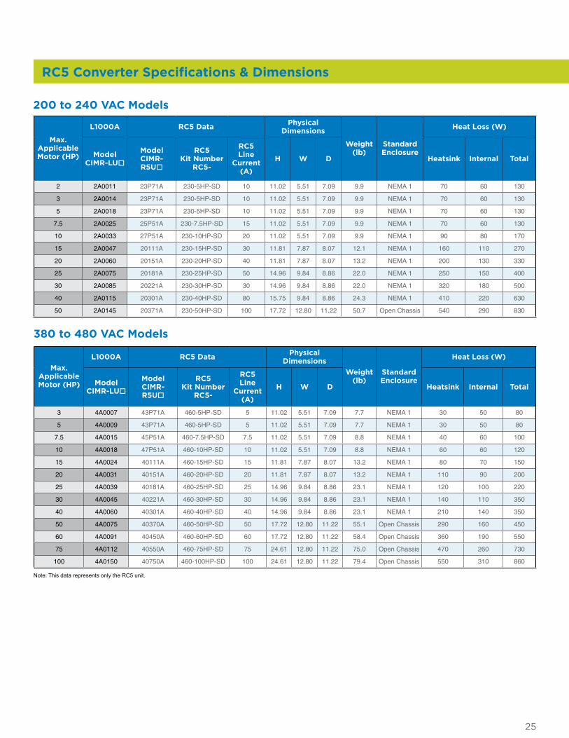
RC5 Converter Specifications & Dimensions
Max. Applicable Motor (HP)
L1000A RC5 Data Physical Dimensions
Weight(lb)
StandardEnclosure
Heat Loss (W)
Model CIMR-LUo
Model CIMR- R5Uo
RC5 Kit Number
RC5-
RC5 Line
Current (A)
H W D Heatsink Internal Total
3 4A0007 43P71A 460-5HP-SD 5 11.02 5.51 7.09 7.7 NEMA 1 30 50 80
5 4A0009 43P71A 460-5HP-SD 5 11.02 5.51 7.09 7.7 NEMA 1 30 50 80
7.5 4A0015 45P51A 460-7.5HP-SD 7.5 11.02 5.51 7.09 8.8 NEMA 1 40 60 100
10 4A0018 47P51A 460-10HP-SD 10 11.02 5.51 7.09 8.8 NEMA 1 60 60 120
15 4A0024 40111A 460-15HP-SD 15 11.81 7.87 8.07 13.2 NEMA 1 80 70 150
20 4A0031 40151A 460-20HP-SD 20 11.81 7.87 8.07 13.2 NEMA 1 110 90 200
25 4A0039 40181A 460-25HP-SD 25 14.96 9.84 8.86 23.1 NEMA 1 120 100 220
30 4A0045 40221A 460-30HP-SD 30 14.96 9.84 8.86 23.1 NEMA 1 140 110 350
40 4A0060 40301A 460-40HP-SD 40 14.96 9.84 8.86 23.1 NEMA 1 210 140 350
50 4A0075 40370A 460-50HP-SD 50 17.72 12.80 11.22 55.1 Open Chassis 290 160 450
60 4A0091 40450A 460-60HP-SD 60 17.72 12.80 11.22 58.4 Open Chassis 360 190 550
75 4A0112 40550A 460-75HP-SD 75 24.61 12.80 11.22 75.0 Open Chassis 470 260 730
100 4A0150 40750A 460-100HP-SD 100 24.61 12.80 11.22 79.4 Open Chassis 550 310 860
Max. Applicable Motor (HP)
L1000A RC5 Data Physical Dimensions
Weight(lb)
StandardEnclosure
Heat Loss (W)
Model CIMR-LUo
Model CIMR- R5Uo
RC5 Kit Number
RC5-
RC5 Line
Current (A)
H W D Heatsink Internal Total
2 2A0011 23P71A 230-5HP-SD 10 11.02 5.51 7.09 9.9 NEMA 1 70 60 130
3 2A0014 23P71A 230-5HP-SD 10 11.02 5.51 7.09 9.9 NEMA 1 70 60 130
5 2A0018 23P71A 230-5HP-SD 10 11.02 5.51 7.09 9.9 NEMA 1 70 60 130
7.5 2A0025 25P51A 230-7.5HP-SD 15 11.02 5.51 7.09 9.9 NEMA 1 70 60 130
10 2A0033 27P51A 230-10HP-SD 20 11.02 5.51 7.09 9.9 NEMA 1 90 80 170
15 2A0047 20111A 230-15HP-SD 30 11.81 7.87 8.07 12.1 NEMA 1 160 110 270
20 2A0060 20151A 230-20HP-SD 40 11.81 7.87 8.07 13.2 NEMA 1 200 130 330
25 2A0075 20181A 230-25HP-SD 50 14.96 9.84 8.86 22.0 NEMA 1 250 150 400
30 2A0085 20221A 230-30HP-SD 30 14.96 9.84 8.86 22.0 NEMA 1 320 180 500
40 2A0115 20301A 230-40HP-SD 80 15.75 9.84 8.86 24.3 NEMA 1 410 220 630
50 2A0145 20371A 230-50HP-SD 100 17.72 12.80 11.22 50.7 Open Chassis 540 290 830
200 to 240 VAC Models
380 to 480 VAC Models
Note: This data represents only the RC5 unit.
26
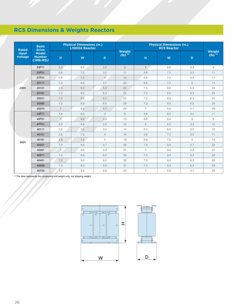
RC5 Dimensions & Weights Reactors
Rated Input
Voltage
Basic Drive Model
Number CIMR-R5U
Physical Dimensions (in.) L1000A Reactor
Weight (lb) (1)
Physical Dimensions (in.) RC5 Reactor
Weight (lb) (1)
H W D H W D
230V
23P71 5.3 6.0 3.2 9 5 6.0 3.3 9
25P51 5.8 7.2 3.5 11 5.8 7.2 3.5 11
27P51 5.8 7.2 4 14 5.8 7.2 3.5 11
20111 7.4 9.0 4.7 23 5.8 7.2 4 14
20151 7.3 9.0 5.3 24 7.3 9.0 5.3 24
20181 7.2 9.0 6.3 25 7.2 9.0 6.3 25
20221 7.2 9.0 6.3 25 7.2 9.0 6.3 25
20300 7.2 9.0 6.5 29 7.3 9.0 6.5 29
20370 7 9.0 4.7 29 7 9.0 4.7 29
460V
43P71 4.8 6.0 3 8 4.8 6.0 3.4 11
45P51 5 6.0 3.3 10 4.8 6.0 3 8
47P51 5.3 6.0 3.5 12 5 6.0 3.3 10
40111 5.8 7.2 3.5 14 5.3 6.0 3.5 12
40151 5.8 7.2 4 16 5.8 7.2 3.5 11
40181 5.8 7.2 4 16 5.8 7.2 4 14
40221 7.4 9.0 4.7 28 7.4 9.0 4.7 23
40301 7 9.0 5.3 27 7 9.0 5.3 27
40371 7.2 9.0 6.5 33 7.2 9.0 6.5 33
40451 7.2 9.0 6.5 33 7.2 9.0 6.3 25
40550 7.3 9.0 6.8 37 7.3 9.0 6.5 29
40750 7.2 9.0 6.8 43 7 9.0 4.7 29
(1) The data represents the component unit weight only, not shipping weight.
H
DW
27
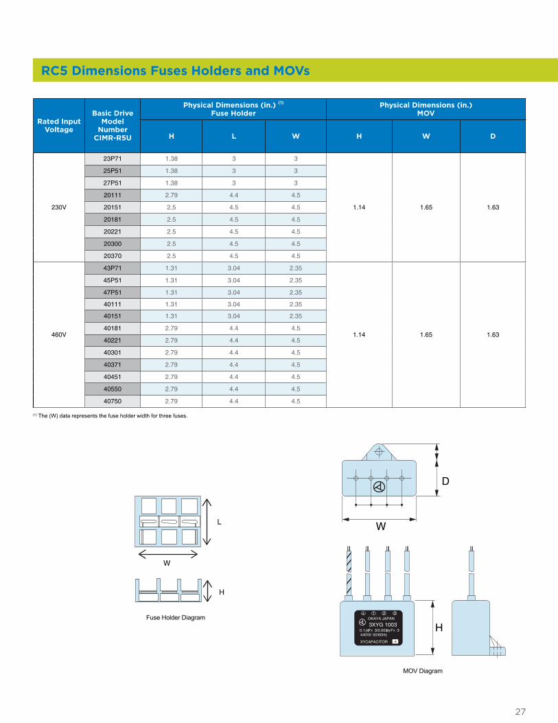
RC5 Dimensions Fuses Holders and MOVs
Rated Input Voltage
Basic Drive Model
Number CIMR-R5U
Physical Dimensions (in.) (1) Fuse Holder
Physical Dimensions (in.) MOV
H L W H W D
230V
23P71 1.38 3 3
1.14 1.65 1.63
25P51 1.38 3 3
27P51 1.38 3 3
20111 2.79 4.4 4.5
20151 2.5 4.5 4.5
20181 2.5 4.5 4.5
20221 2.5 4.5 4.5
20300 2.5 4.5 4.5
20370 2.5 4.5 4.5
460V
43P71 1.31 3.04 2.35
1.14 1.65 1.63
45P51 1.31 3.04 2.35
47P51 1.31 3.04 2.35
40111 1.31 3.04 2.35
40151 1.31 3.04 2.35
40181 2.79 4.4 4.5
40221 2.79 4.4 4.5
40301 2.79 4.4 4.5
40371 2.79 4.4 4.5
40451 2.79 4.4 4.5
40550 2.79 4.4 4.5
40750 2.79 4.4 4.5
(1) The (W) data represents the fuse holder width for three fuses.
OKAYA JAPAN
3XYG 1003
440V 50/60Hz
XYCAPACITOR
0.1 F× 3/0.003 F× 3m m
1 2 3
-4
W
D
H
L
H
W
Fuse Holder Diagram
MOV Diagram
28
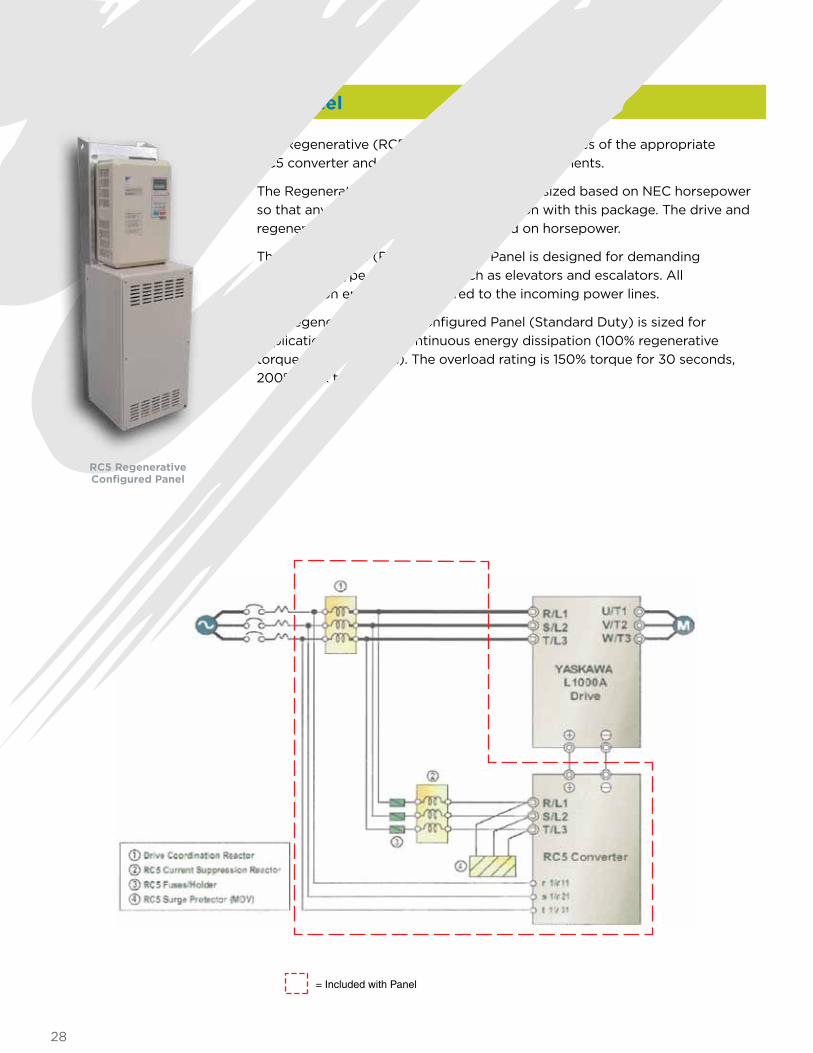
Regenerative Configured Panel
The Regenerative (RC5) Configured Panel comprises of the appropriate RC5 converter and all necessary external components.
The Regenerative (RC5) Configured Panel is sized based on NEC horsepower so that any drive can be used in conjunction with this package. The drive and regenerative kit should be sized 1:1 based on horsepower.
The Regenerative (RC5) Configured Panel is designed for demanding “hold-back” type applications, such as elevators and escalators. All regeneration energy is transferred to the incoming power lines.
The Regenerative (RC5) Configured Panel (Standard Duty) is sized for applications requiring continuous energy dissipation (100% regenerative torque for 60 seconds). The overload rating is 150% torque for 30 seconds, 200% peak torque.
= Included with Panel
RC5 Regenerative Configured Panel
29
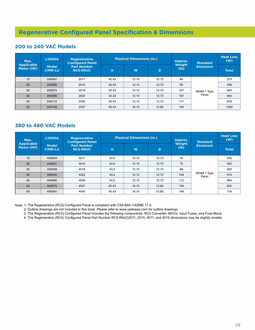
Regenerative Configured Panel Specification & Dimensions
Max. Applicable Motor (HP)
L1000A
Model CIMR-LU
Regenerative Configured Panel
Part Number RC5-R5UC
Physical Dimensions (in.)Approx. Weight
(lb)
Standard Enclosure
Heat Loss (W)
H W D Total
15 2A0047 2011 42.43 12.15 12.73 84
NEMA 1 Type Panel
373
20 2A0060 2015 42.43 12.15 12.73 96 458
25 2A0075 2018 42.43 12.15 12.73 107 564
30 2A0085 2022 42.43 12.15 12.73 107 664
40 2A0115 2030 42.43 12.15 12.73 117 818
50 2A0145 2037 45.43 16.15 12.82 144 1040
200 to 240 VAC Models
Max. Applicable Motor (HP)
L1000A
Model CIMR-LU
Regenerative Configured Panel
Part Number RC5-R5UC
Physical Dimensions (in.)Approx. Weight
(lb)
Standard Enclosure
Heat Loss (W)
H W D Total
15 4A0024 4011 43.2 12.15 12.73 74
NEMA 1 Type Panel
245
20 4A0031 4015 43.2 12.15 12.73 75 302
25 4A0039 4018 43.2 12.15 12.73 88 323
30 4A0045 4022 43.2 12.15 12.73 109 474
40 4A0060 4030 43.2 12.15 12.73 112 484
50 4A0075 4037 45.43 16.15 12.82 156 622
60 4A0091 4045 45.43 16.15 12.82 159 718
380 to 480 VAC Models
Note: 1. The Regenerative (RC5) Configured Panel is compliant with CSA B44.1/ASME 17.5. 2. Outline drawings are not included in this book. Please refer to www.yaskawa.com for outline drawings. 3. The Regenerative (RC5) Configured Panel includes the following components: RC5 Converter, MOVs, Input Fuses, and Fuse Block. 4. The Regenerative (RC5) Configured Panel Part Number RC5-R5UC2011, 2015, 4011, and 4015 dimensions may be slightly smaller.

30

31
FOLD
Yaskawa America, Inc. Drives & Motion Division
2121 Norman Drive South Waukegan, IL 60085
1-800-YASKAWA (927-5292) • Local: 847-887-7000 • Fax: 1-847-887-7310
[email protected] • www.yaskawa.com
Document BL.L1000A.01 05/01/12 • © 2012