gic modeling - western electricity coordinating council · • gic modeling data ... –gic add-on...
TRANSCRIPT
GIC Modeling SRWG Meeting
March 2014
Introduction
• Terminology
• Theory
• GMD Impacts to Power System Equipment
• Historic Events
• Regulatory Activities
• Geomagnetic Induced Current Modeling
• GIC Study Tools
• GIC Modeling Data
• Challenges
• IPCO GIC Study Experiences
• SRWG Discussion Topics
Terminology
• CME = Coronal Mass Ejection
• GMD = Geomagnetic Disturbance
• GIC = Geomagnetically Induced Current
• HILF = High Impact Low Frequency Events
– Coordinated Cyber, Physical, and Blended Attacks
– Pandemics
– Geomagnetic Disturbances
– Electromagnetic Pulse (EMP)
– Intentional Electromagnetic Interference (IEMI)
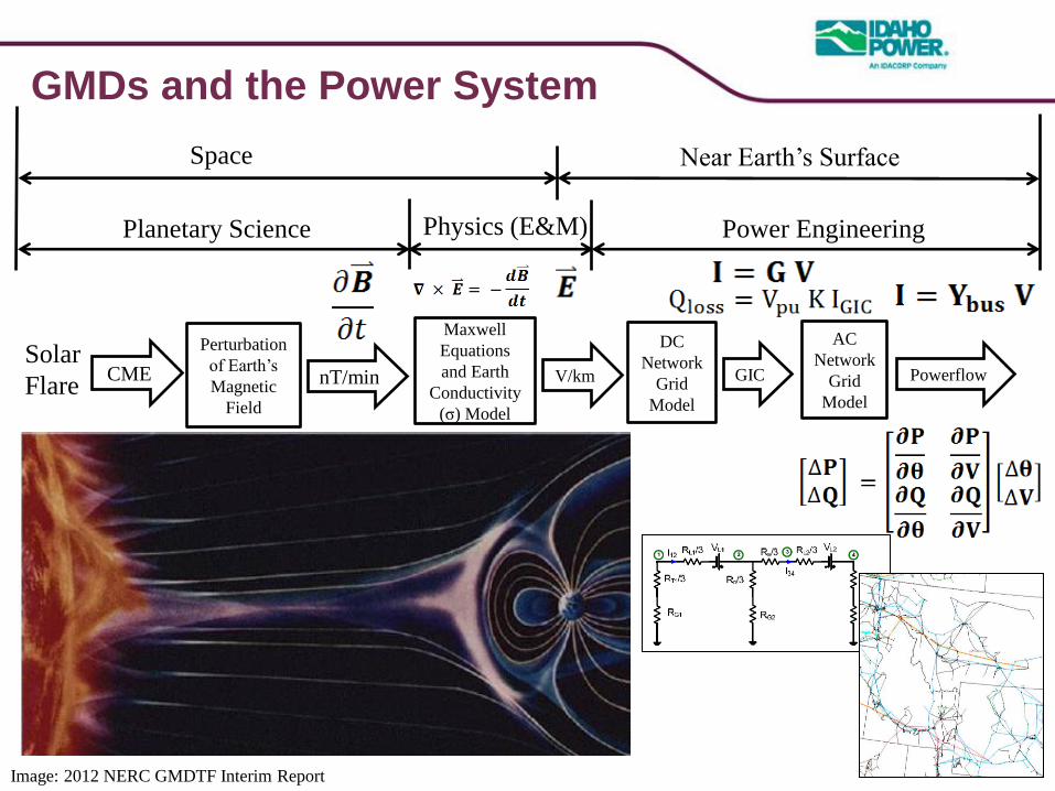
GMDs and the Power System
DC
Network
Grid
Model
GIC
AC
Network
Grid
Model
Powerflow Solar
Flare CME
Perturbation
of Earth’s
Magnetic
Field
nT/min
Planetary Science
Space
Image: 2012 NERC GMDTF Interim Report
Maxwell
Equations
and Earth
Conductivity
(σ) Model
V/km
Physics (E&M) Power Engineering
Near Earth’s Surface
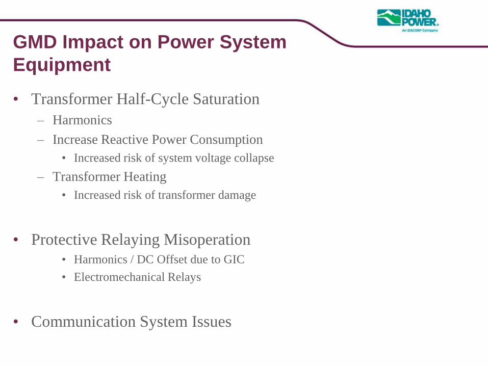
GMD Impact on Power System
Equipment
• Transformer Half-Cycle Saturation
– Harmonics
– Increase Reactive Power Consumption
• Increased risk of system voltage collapse
– Transformer Heating
• Increased risk of transformer damage
• Protective Relaying Misoperation
• Harmonics / DC Offset due to GIC
• Electromechanical Relays
• Communication System Issues
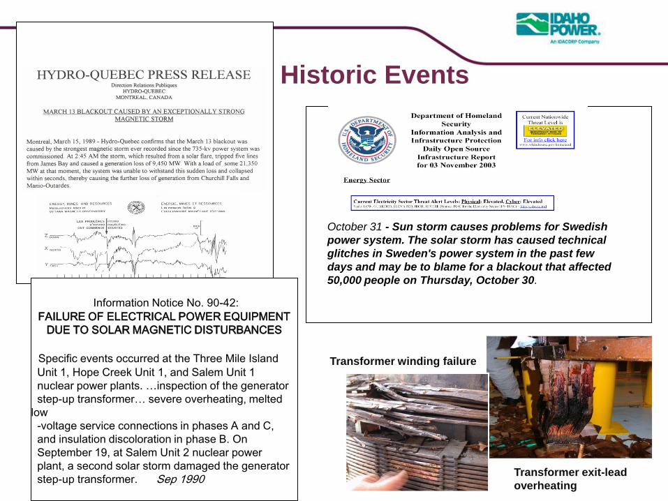
October 31 - Sun storm causes problems for Swedish
power system. The solar storm has caused technical
glitches in Sweden's power system in the past few
days and may be to blame for a blackout that affected
50,000 people on Thursday, October 30.
Information Notice No. 90-42:
FAILURE OF ELECTRICAL POWER EQUIPMENT
DUE TO SOLAR MAGNETIC DISTURBANCES
Specific events occurred at the Three Mile Island
Unit 1, Hope Creek Unit 1, and Salem Unit 1
nuclear power plants. …inspection of the generator
step-up transformer… severe overheating, melted
low
-voltage service connections in phases A and C,
and insulation discoloration in phase B. On
September 19, at Salem Unit 2 nuclear power
plant, a second solar storm damaged the generator
step-up transformer. Sep 1990
Transformer exit-lead
overheating
Transformer winding failure
Historic Events
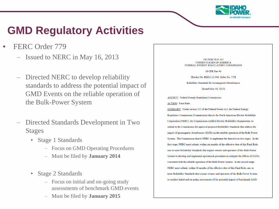
GMD Regulatory Activities
• FERC Order 779
– Issued to NERC in May 16, 2013
– Directed NERC to develop reliability
standards to address the potential impact of
GMD Events on the reliable operation of
the Bulk-Power System
– Directed Standards Development in Two
Stages
• Stage 1 Standards
– Focus on GMD Operating Procedures
– Must be filed by January 2014
• Stage 2 Standards
– Focus on initial and on-going study
assessments of benchmark GMD events
– Must be filed by January 2015
NERC Project 2013-03
Geomagnetic Disturbance Mitigation
• Stage 1: NERC EOP-010-1 Geomagnetic Disturbance Operations
– NERC BOT adoption 11/7/2013
– Filed with FERC 11/14/2013
• Stage 2: NERC TPL-007-1 Transmission System Planned
Performance During Geomagnetic Disturbances
– Standards Authorization Request (SAR) Completed
– Status = Active Formal Development
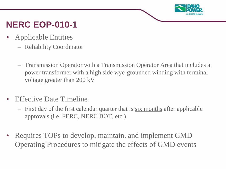
NERC EOP-010-1
• Applicable Entities
– Reliability Coordinator
– Transmission Operator with a Transmission Operator Area that includes a
power transformer with a high side wye-grounded winding with terminal
voltage greater than 200 kV
• Effective Date Timeline
– First day of the first calendar quarter that is six months after applicable
approvals (i.e. FERC, NERC BOT, etc.)
• Requires TOPs to develop, maintain, and implement GMD
Operating Procedures to mitigate the effects of GMD events

NERC TPL-007-1
• FERC Order 779 Requirements
– Initial and on-going assessments of the risk and potential impact of
benchmark GMD events on the Bulk-Power System
– Identification of benchmark GMD events
– Develop and implement action plans to protect against instability,
uncontrolled separation, or cascading caused by GMD events
• Proposed Effective Date Timeline
– Implementation Period was not addressed in Order 779
• Potential Impact to SRWG
– May need to develop GIC Modeling and Data Reporting Requirements
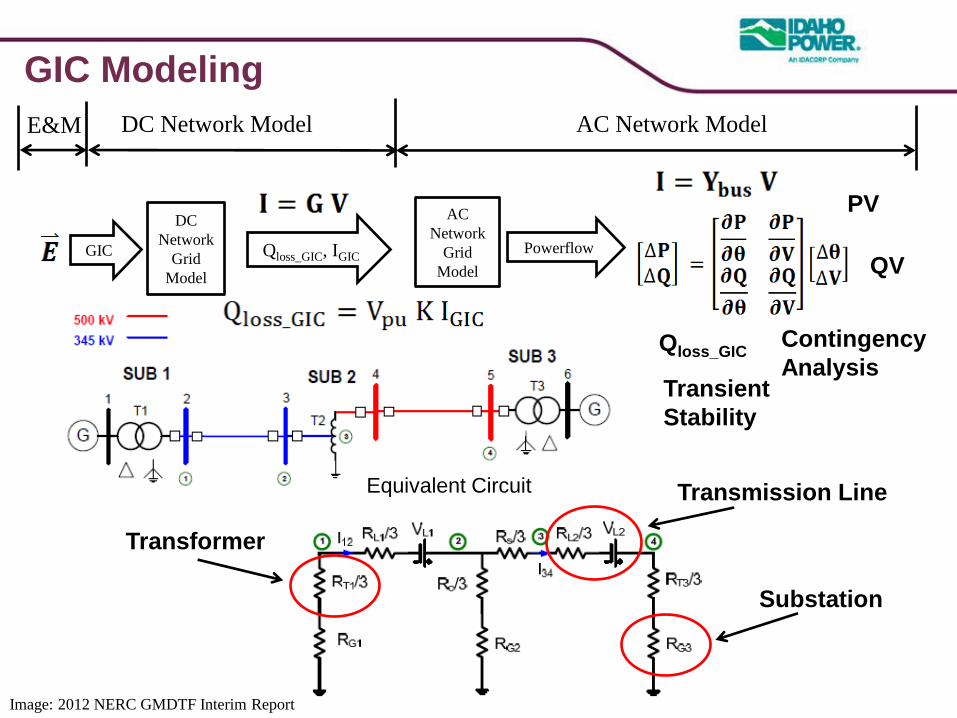
GIC Modeling
Image: 2012 NERC GMDTF Interim Report
Qloss_GIC, IGIC QV
PV DC
Network
Grid
Model
GIC
AC
Network
Grid
Model
Powerflow
Qloss_GIC
Contingency
Analysis Transient
Stability
E&M DC Network Model AC Network Model
Equivalent Circuit
Substation
Transmission Line
Transformer
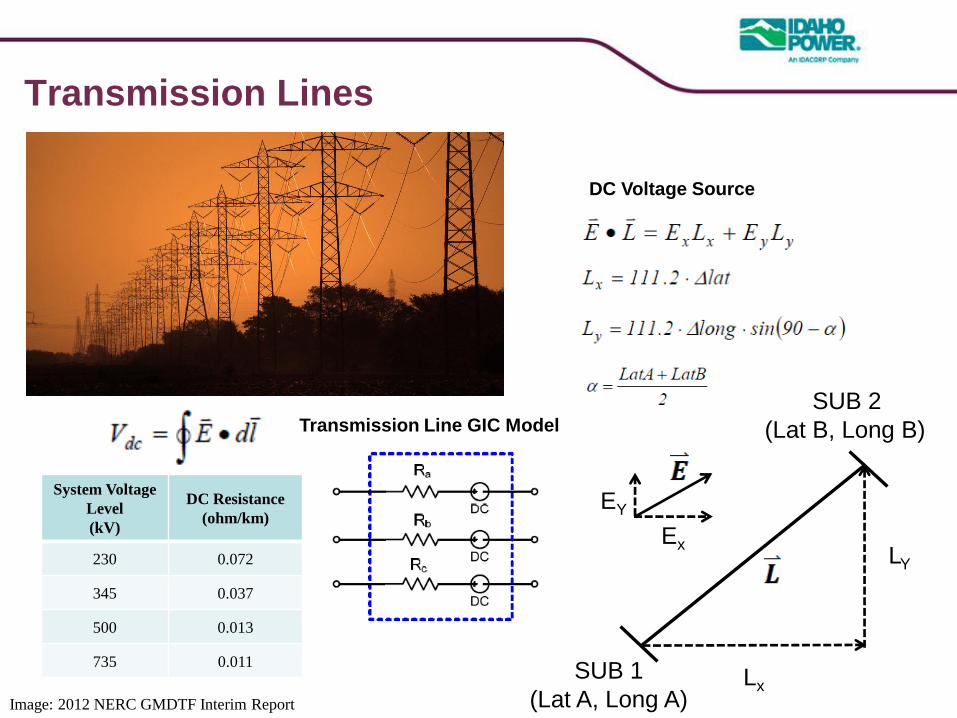
Transmission Lines
Image: 2012 NERC GMDTF Interim Report
DC Voltage Source
Transmission Line GIC Model
LY
SUB 1
(Lat A, Long A)
SUB 2
(Lat B, Long B)
Ex
EY
Lx
System Voltage
Level
(kV)
DC Resistance
(ohm/km)
230 0.072
345 0.037
500 0.013
735 0.011
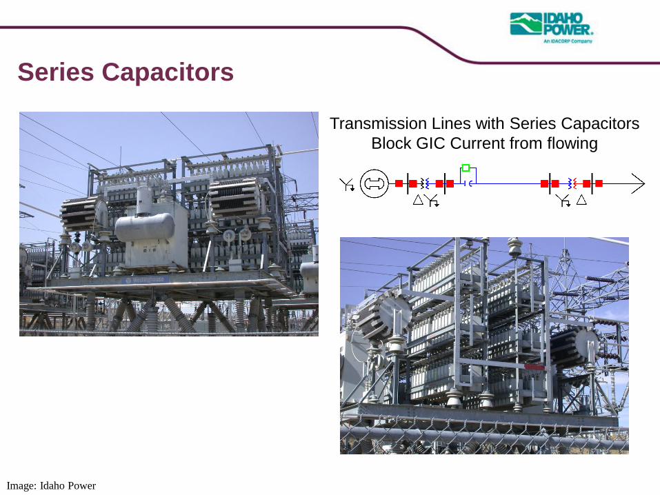
Series Capacitors
Transmission Lines with Series Capacitors
Block GIC Current from flowing
Image: Idaho Power
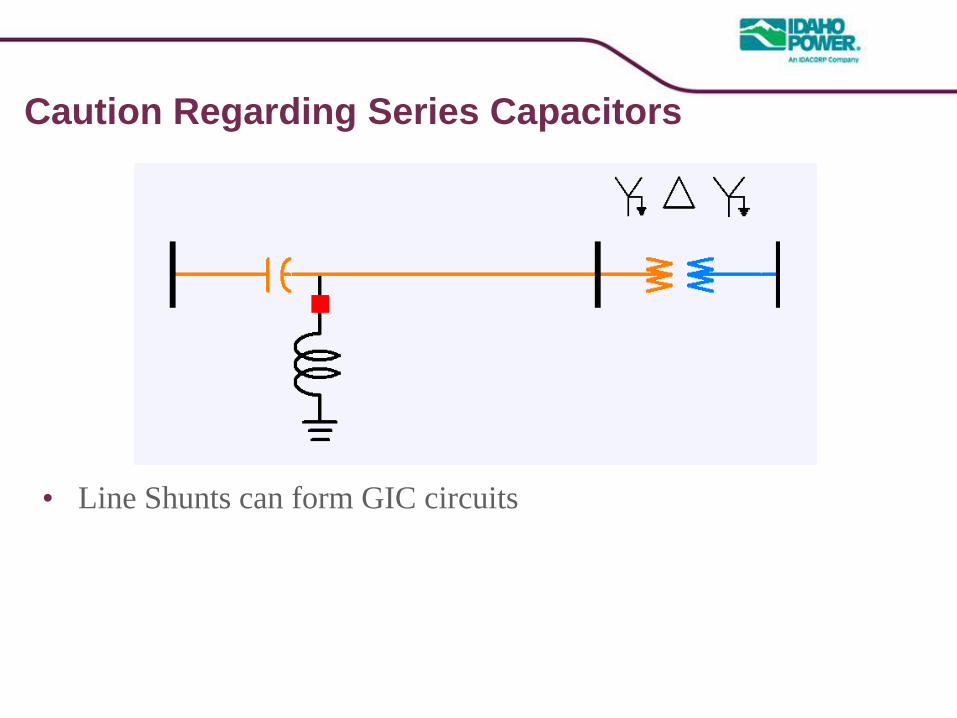
Caution Regarding Series Capacitors
• Line Shunts can form GIC circuits
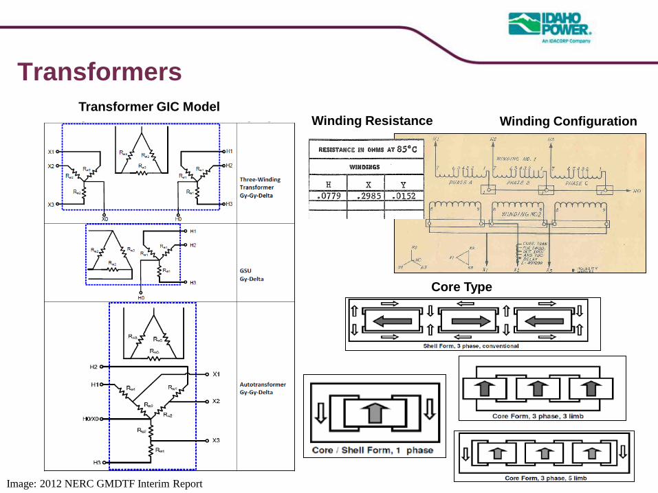
Transformers
Transformer GIC Model
Image: 2012 NERC GMDTF Interim Report
Winding Configuration Winding Resistance
Core Type
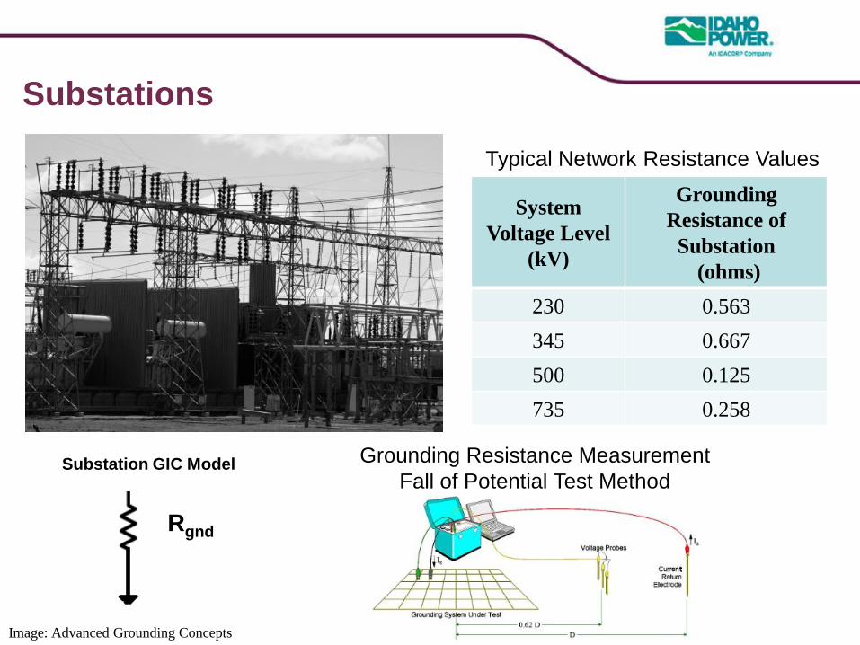
Substations
Typical Network Resistance Values
Image: Advanced Grounding Concepts
Grounding Resistance Measurement
Fall of Potential Test Method
System
Voltage Level
(kV)
Grounding
Resistance of
Substation
(ohms)
230 0.563
345 0.667
500 0.125
735 0.258
Substation GIC Model
Rgnd

GIC Study Tools
• General Electric Positive Sequence Load Flow (GE PSLF)
– GIC add-on module available in GE PSLF V18.1_02
• Latitude / Longitude in bus record table
• Four New tables for Substation, secddg table, trang table, e-field table
• Siemens Power System Simulator for Engineering (PSS®E)
– GIC add-on module available in Versions 32.2 and 33.3
• Input data via auxiliary text file *.GIC file or GIC module GUI
• PowerWorld Simulator V17
– GIC add-on module available
• Input data via auxiliary text file or GIC Add-on Analysis Dialog
• Calculation Methods are based on NERC GMD Task Force
Recommendations
• Default values for some GIC data if unknown
GIC Modeling Data
• GIC Modeling Data on an wide area basis
– Powerflow Network
– Latitude / Longitude of Substations
– Substation Grounding Resistance
– Transformer Connections
– Transformer DC Winding Resistance
– Status of GIC Blocking Devices
• Equipment Specific GIC Modeling Data
– Transformer Core Construction
– Transformer Saturation Coefficient (K-Factor)
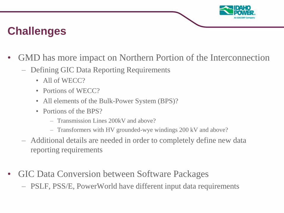
Challenges
• GMD has more impact on Northern Portion of the Interconnection
– Defining GIC Data Reporting Requirements
• All of WECC?
• Portions of WECC?
• All elements of the Bulk-Power System (BPS)?
• Portions of the BPS?
– Transmission Lines 200kV and above?
– Transformers with HV grounded-wye windings 200 kV and above?
– Additional details are needed in order to completely define new data
reporting requirements
• GIC Data Conversion between Software Packages
– PSLF, PSS/E, PowerWorld have different input data requirements
Needs
• GIC studies should be performed using Wide Area Models
• GIC Data needs to be available and shared between Entities
• GIC Blocking in one Area impacts GIC currents in adjacent Areas
– Whack-a-Mole
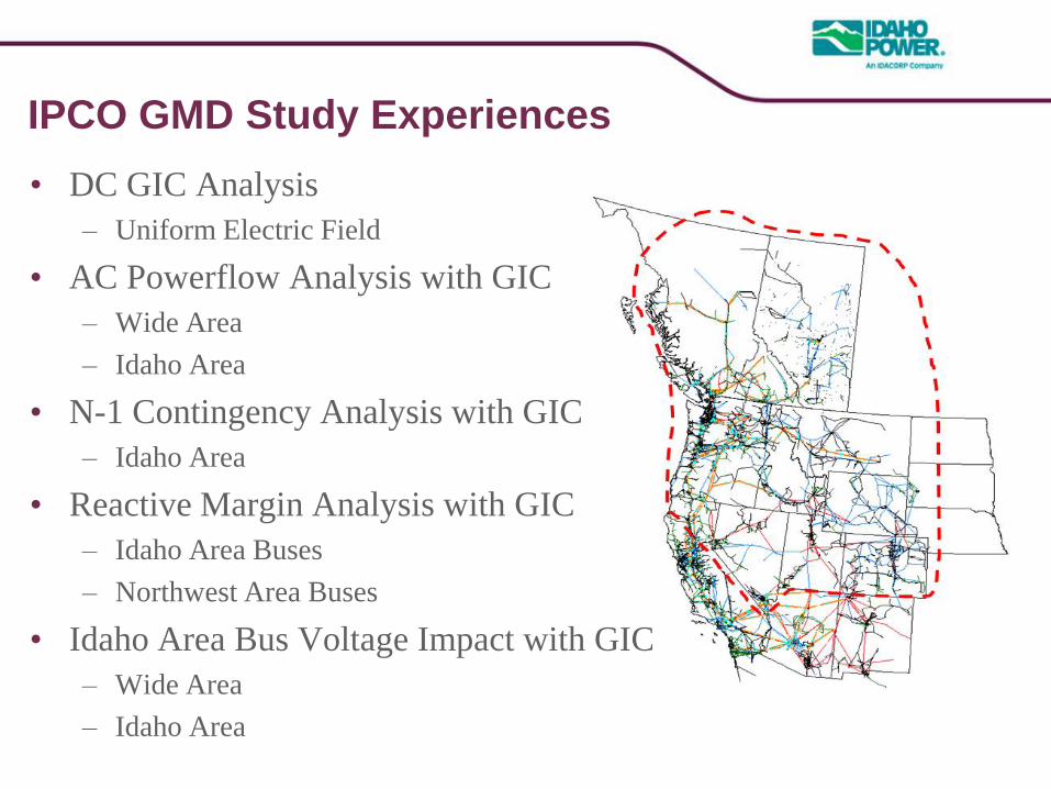
IPCO GMD Study Experiences
• DC GIC Analysis
– Uniform Electric Field
• AC Powerflow Analysis with GIC
– Wide Area
– Idaho Area
• N-1 Contingency Analysis with GIC
– Idaho Area
• Reactive Margin Analysis with GIC
– Idaho Area Buses
– Northwest Area Buses
• Idaho Area Bus Voltage Impact with GIC
– Wide Area
– Idaho Area
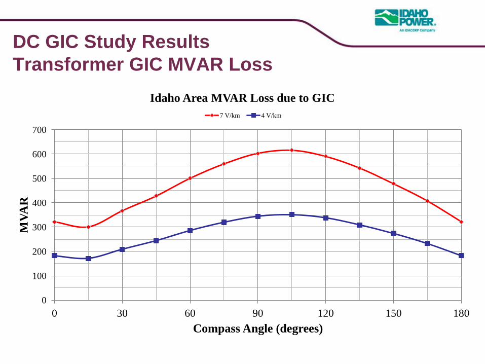
DC GIC Study Results
Transformer GIC MVAR Loss
0
100
200
300
400
500
600
700
0 30 60 90 120 150 180
MV
AR
Compass Angle (degrees)
Idaho Area MVAR Loss due to GIC
7 V/km 4 V/km
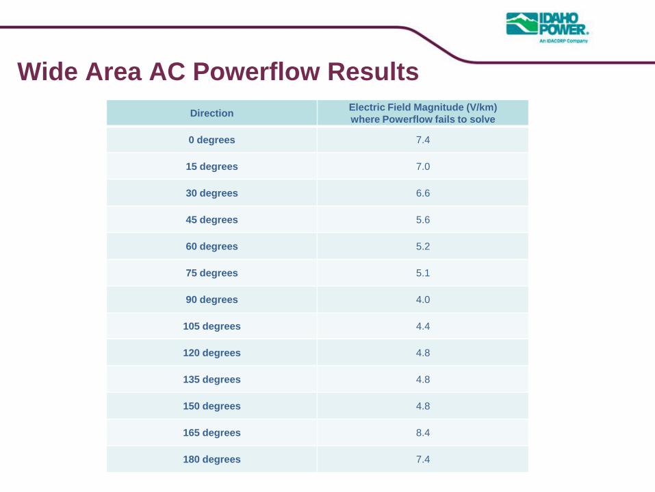
Wide Area AC Powerflow Results
Direction Electric Field Magnitude (V/km)
where Powerflow fails to solve
0 degrees 7.4
15 degrees 7.0
30 degrees 6.6
45 degrees 5.6
60 degrees 5.2
75 degrees 5.1
90 degrees 4.0
105 degrees 4.4
120 degrees 4.8
135 degrees 4.8
150 degrees 4.8
165 degrees 8.4
180 degrees 7.4
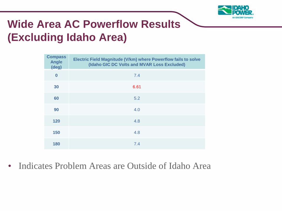
Wide Area AC Powerflow Results
(Excluding Idaho Area)
Compass
Angle
(deg)
Electric Field Magnitude (V/km) where Powerflow fails to solve
(Idaho GIC DC Volts and MVAR Loss Excluded)
0 7.4
30 6.61
60 5.2
90 4.0
120 4.8
150 4.8
180 7.4
• Indicates Problem Areas are Outside of Idaho Area
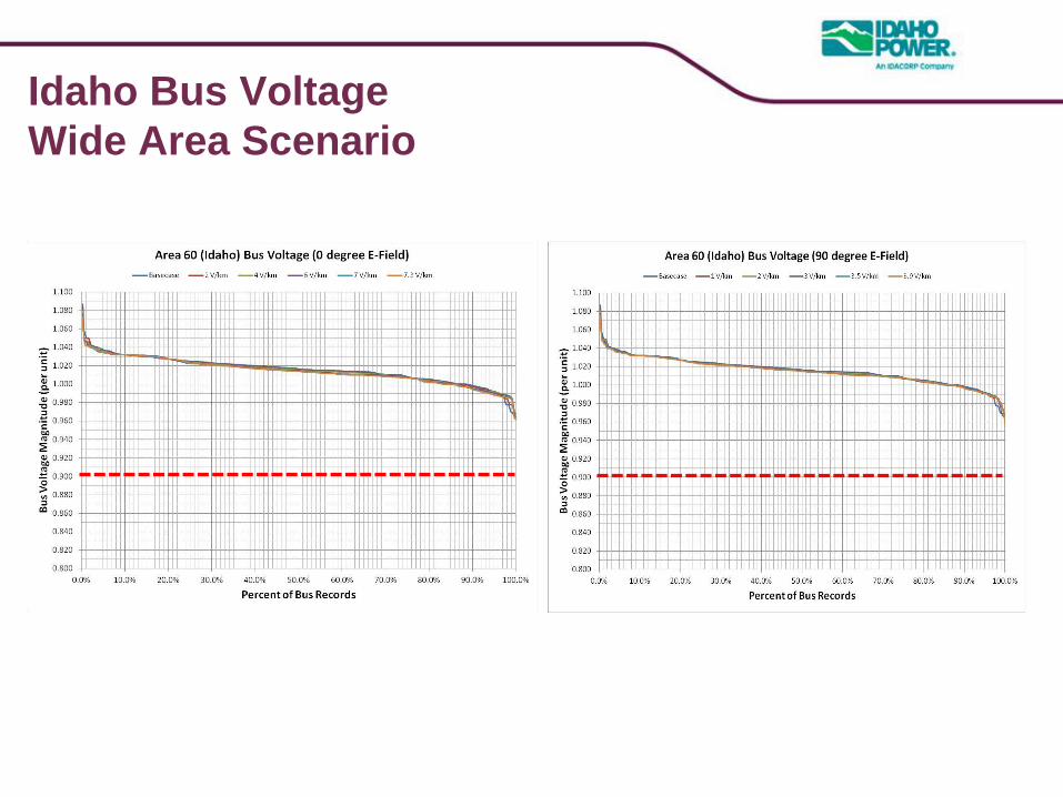
Idaho Bus Voltage
Wide Area Scenario
SRWG Discussion Topics
• As network modelers – we should start thinking about how we are
going to collect and maintain GIC Modeling Data
• GIC Modeling and Data Reporting Requirements
– Include in DPM?
– Include as part of WECC basecase data?
– Include in separate GIC database?
• data submittal process similar to PRC-006-WECC-CRT-1
– Include GIC data tables in the BCCS?
– Regional Standard / Regional Business Practice / Regional Criteria
• Until a draft Version of TPL-007-1 is available, it might be too
soon to completely define GIC Data Reporting Requirements
• WECC Regional Criteria for TPL-007-1
– WECC Regional Criteria contain data reporting requirements
Questions
Eric Bakie, P.E.
SYSTEM PLANNING ENGINEER
Idaho Power | System Planning
(208) 388-5677