i.c.e series add on cooling installation, start...
TRANSCRIPT

I.C.E SERIES ADD ON COOLING
INSTALLATION, START-UP & MAINTENANCE INSTRUCTIONS
10, 12, 15kW (Single Phase) & 15, 18, 21kW (Three Phase) Models
APPLICATION The Brivis ICE Series Add-On Cooling is a refrigerated, cooling only, split type air conditioner designed for connection to a Brivis Ducted Central Heating System. Brivis Add-On Cooling utilises the heating system’s ductwork and air circulation fan to distribute cool, filtered refrigerated air. Brivis ICE Series Add-On Cooling is available in five models ranging in capacity from 10 to 21 kW. The Selection Chart below illustrates the recommended maximum size Brivis ICE Series Add-On Cooling model that can be installed with each of the current Brivis Heater models. Please contact Brivis when matching Add-On Cooling to any other existing Brivis Heater Model that is not listed below. PLEASE NOTE THIS MANUAL CONTAINS A NEW AND OLD MATCHING GUIDE TO ENSURE THE CORRECT UNIT IS INSTALLED. NEW BRIVIS ICE RANGE
Brivis Heater Model Recommended Outdoor Model
Recommended Indoor Model
Nominal Cooling Capacity (kW)
MPS 20 Std V3 CDU12A-7H IDU12A 12
MPS 20 XA V3 CDU15A-7H / 7D / 9 IDU15A 15
MPS 30 Std V3 CDU18A-9 IDU18A 18
MPS 30 XA V3 CDU18A-9 IDU18A 18
MPS 35 Std V3 38CDA21A9 28IDA21A7 21
Buffalo 15 & 20 Std CDU10A-7H IDU10A 10
Buffalo 20 XA CDU10A-7H IDU10A 10
Buffalo 26 Std CDU12A-7H IDU12A 12
Buffalo 26 XA CDU18A-9 IDU18A 18
2PW 15 Std CDU10A-7H IDU18A 10
2PW 20 Std CDU10A-7H IDU10A 10
2PW 20 XA CDU12A-7H IDU12A 12
2PW 26 Std CDU15A-7H / 7D / 9 IDU15A 15
2PW 26 XA CDU18A-9 IDU18A 18
EMS 20 Std CDU10A-7H IDU10A 10
EMS 20 XA CDU10A-7H IDU10A 10
EMS 26 Std CDU12A-7H IDU12A 12
EMS 26 XA CDU15A-7H / 7D / 9 IDU15A 15
Doc No. Rev
SU000025 B
The Manufacturer reserves the right to discontinue or change specifications or designs at any time without notice and without incurring obligations. Page 1

The Manufacturer reserves the right to discontinue or change specifications or designs at any time without notice and without incurring obligations. Page 2
OLD BRIVIS ICE RANGE
Brivis Heater Model Recommended Outdoor Model
Recommended Indoor Model
Nominal Cooling Capacity (kW)
MPS 20 Std V3 CDU111C COU111i 10.5 MPS 20 XA V3 CDU114C240 / C415 COU114i 14 MPS 30 Std V3 CDU118C COU118i 17.6 MPS 30 XA V3 CDU118C COU118i 17.6 MPS 35 V3 CDU118C COU118i 17.6 Buffalo 15 & 20 Std CDU107C COU107i 7 Buffalo 20 XA CDU109C COU109i 8.8 Buffalo 26 Std CDU111C COU111i 10.5 Buffalo 26 XA CDU118C COU118i 17.6 2PW 15 Std CDU107C COU107i 7 2PW 20 Std CDU109C COU109i 8.8* 2PW 20 XA CDU111C COU111i 10.5 2PW 26 Std CDU114C240 / C415 COU114i 14 2PW 26 XA CDU118C COU118i 17.6 EMS 20 Std CDU107C COU107i 7 EMS 20 XA CDU109C COU109i 8.8 EMS 26 Std CDU111C COU111i 10.5 EMS 26 XA CDU114C240 / C415 COU114i 14
* With some Brivis Heater models a transition fitting will be required to increase the pop size from the heater to match the inlet pop size of the Add-On Cooling indoor coil. If an installation kit thermistor collar assembly has been used then its diameter should also be increased to match the indoor coil inlet pop diameter. DO NOT REDUCE POP SIZE ON INDOOR COIL The system must be fitted with a correctly sized return air grille that includes a filter, to ensure the indoor evaporator coil does not become blocked with airborne dust and lint. The filter should be easily accessible for regular cleaning. (Refer to the Brivis Heating Installer Manual for minimum recommended return air grille size). If the system uses high-level outlets (e.g. ceiling diffusers), then the Return Air inlet must be at a low level. The Brivis Performance Guarantee may not be valid in ceiling systems with a high level Return Air. Ensure adequate ductwork and fittings sizing, particularly on zoned systems. Where bends are required in ductwork, these must be smooth large radius bends, NOT tight!! Always use minimum R1 insulated ductwork with in-ceiling systems, with all fittings insulated. Care should be taken to ensure minimized external static pressure (resistance) against airflow. Ductwork must be sized to handle the Heater’s total cooling airflow output through the system on either whole home or zoned basis. RECOMMENDED INDOOR/OUTDOOR MATCHING CHART
OLD OUTDOOR UNIT NEW OUTDOOR UNIT OLD INDOOR UNIT YES YES NEW INDOOR UNIT NO YES
GENERAL Read all instructions before proceeding with the installation and start up. Note: This instruction applies to R22 charged units ONLY. This equipment must be installed in accordance with all relevant authority requirements. SAFETY CONSIDERATIONS The unit is designed to provide safe and reliable service when operating within design specifications. To avoid injury to personnel and damage to equipment or property when operating the equipment, the following safe practices should be observed as a minimum. • Check the unit weight (see Outdoor Unit Specifications on page 10) to be sure the lifting equipment is adequate. • Disconnect power to the unit before working on it. • Do not remove access panels or doors until fans have completely stopped. • Do not enter a fan cabinet while the fan is running. Isolate the power first. • Protect materials when welding or flame cutting. Use suitable cloth to contain sparks. Have a fire extinguisher at hand and
ready for immediate use.
The Manufacturer reserves the right to discontinue or change specifications or designs at any time without notice and without incurring obligations. Page 3
PRE-INSTALLATION Remove packaging from unit and any protective foam packing from coils and pipes. Check items received against packing list. Examine unit for damage, which may have occurred in transit. Indoor Units are shipped with a holding charge of dry nitrogen. Check to confirm the holding charge. The Outdoor Units come pre-charged with R22. Notify the manufacturer’s sales representative of any damage. INSTALLATION REQUIREMENTS (OUTDOOR UNIT) Location: The Outdoor Unit must be installed in an area that is well ventilated. Ensure that the minimum clearances outlined on the Outdoor Unit Dimensional drawings (page 10) are maintained, so as to provide adequate service access and proper cooling airflow. Avoid positioning the Outdoor Unit near any reverberating structures such as doors and windows and ensure that there is sufficient distance between it and any adjacent neighbouring property so that “operation noise” emitted from the unit does not exceed the noise (dBA) guidelines as set down by local or state legislation or regulatory bodies. Mounting at ground level: The Outdoor Unit must be mounted on a solid, level foundation. Level and bolt the unit to the foundation, ensuring there is an insulating membrane such as rubber “waffle pad” between the unit feet and the foundation. Mounting on the roof: Ensure that the weight of the Outdoor Unit is not excessive for the design of the roof structure. The unit must be mounted onto either a suitably designed steel frame, ensuring that there is an insulating membrane such as rubber “waffle pad” between the roof structure and the frame for vibration elimination, or mounted onto red gum timber blocks again ensuring that “waffle pad” or similar is fitted between the roof structure and the timber to eliminate vibration. It is not permitted to install timber bearers in the tray section of a steel deck roof as support for the Outdoor Unit as the flow of water in the tray is impeded. The timber should be installed on the ridges of the steel roof sheets to ensure proper roof drainage. Both the metal frame or timber supports must be of sufficient size and length to prevent the Outdoor Unit tipping over in high winds. Electrical Power Supply A qualified Electrician must carry out the electrical installation. The Outdoor Unit must be wired directly from the main switchboard in accordance with Electrical Regulations and the unit’s wiring diagram. An external isolating switch must be installed adjacent to the Outdoor Unit also in accordance with Electrical Regulations. Check SAA Wiring Rules for “Protection” sizing and cable sizes. Short circuit protection for the unit must be supplied at the main switchboard using either a d-curve* circuit breaker (or equivalent), or HRC fuse. Rewireable type fuses must not be used. See Outdoor Unit Specification Sheet (page 9) for electrical information. * d-curve circuit breaker – a circuit breaker designed to provide protection for circuits with high in-rush currents, eg. motor start. INSTALLATION REQUIREMENTS (INDOOR UNIT) Location: Choose a location that is suitable for refrigeration piping and condensate drainage and so that adequate provision is made for service access. The Indoor unit is not weatherproof and should be installed so that there is no chance of direct sunlight or water/moisture coming into contact with the outer casing. Where the unit is installed in the roof or ceiling space it must be mounted on a working platform ensuring that the building structure is capable of supporting the unit’s weight. The Indoor Unit must be installed downstream of the Heater’s main Supply Air Outlet and located as far away from the heater as possible, but always before the first branch-take-off (B.T.O.) fitting. If the Heater has a remote thermistor installed in the supply air ductwork, the evaporator coil should be positioned downstream of the thermistor. If the evaporator coil is positioned before the thermistor, it will adversely affect the heater’s performance. Never put the Indoor Unit in the Return Air part of the duct system, this would result in condensation forming in the Heater, causing corrosion and damage to vital components. Ensure that a minimum of 1 metre or 2½ times the duct diameter (whichever is greater) of straight ductwork is installed immediately downstream of the Indoor Unit before any divergence or branch-take-offs occur. Failure to do this will void the warranty.

Condensate Drain: The Indoor Unit incorporates an evaporator drip tray and is supplied with a 20mm Female Pressure Pipe drain spigot, which is to be connected to the supplied "V" trap. Always install the “V” trap as close to the unit as possible. Fill the "V" trap with water during installation before starting unit, to prevent air movement through the drainpipe. It is imperative that the drain trap contains water at all times. Adjust the level of the fan coil unit to ensure that the condensate drains from the evaporator drip tray (approx 10 - 15mm incline from back to front).
A non-flexible drainpipe should then be installed for condensate run-off. This drainpipe is to have a continuous downward grade away from the unit, not less than 1:50. When the Indoor Unit is installed in a roof or ceiling space, an additional Safety Drain Tray (not supplied) must also be installed under the Indoor Unit. This Safety Tray must also be separately drained and the drain arranged to terminate in a position where the end user could see if water was dripping from the outlet. Please instruct the end user to call Brivis Service should they notice water dripping from the Safety Tray drain outlet. (see diagram on next page) Minimum Service Clearances: For servicing, a minimum clearance of 600mm must be provided in front of the access panel side of the unit for its entire length. Where installed on a platform in the roof space, the platform should also extend 600mm out in front of the access panel side of the unit for its entire length. A 600mm wide platform is required to connect between the indoor unit and the access opening or the ducted heating unit for the purpose of access and adequate lighting needs to be installed. Duct work should not be installed across the platform preventing safe access.
The Manufacturer reserves the right to discontinue or change specifications or designs at any time without notice and without incurring obligations. Page 4

TYPICAL INDOOR UNIT INSTALLATION
The manufacturer reserves the right to discontinue or change specifications or designs at any time without notice and without incurring obligations. Page. 5

The manufacturer reserves the right to discontinue or change specifications or designs at any time without notice and without incurring obligations. Page. 6
REFRIGERANT PIPING Piping Design Pipework must be installed in a manner which prevents drainage of liquid into the compressor and ensures adequate oil return. Pipes should be run as directly as possible between indoor and outdoor units. Horizontal Pipes Any buried pipes should be insulated and located in a plastic duct, complete with a vapour seal. The buried distance must not exceed 5 metres and a liquid line solenoid valve must be located adjacent to the indoor unit. The solenoid valve must be interlocked with the compressor. Vertical Pipes The height difference between indoor and outdoor units must not exceed 10 metres. If the outdoor unit is located more than 6 metres above the indoor unit, a liquid line solenoid valve must be located adjacent to the indoor unit to protect against refrigerant migration. The solenoid valve must be interlocked with the compressor. PIPING & CHARGING Warning: Both indoor and outdoor units come delivered under positive pressure. The outdoor unit is charged with sufficient refrigerant R22 to satisfy a connecting pipe run of 15m actual length. The indoor unit is pressurised with approx. 700kPaG (100 psi.) dry nitrogen. Connecting pipe blanking plates must not be removed until the installer is sure the plates are not under positive pressure. Read all piping notes below before starting installation. General The following good piping practices should be adhered to during installation: • A 3” one-way filter drier must always be installed, to contain particles and absorb any moisture. (Depending on the
unit’s date of manufacture, this filter/drier has been supplied by Brivis, either as a separate component or as an integral part of the Outdoor Condensing Unit. Where the filter/drier has been supplied as a separate component it is the installers responsibility to ensure that it is correctly installed on the liquid line before commissioning the system).
• Use new, clean and sealed refrigeration grade pipe. • Keep pipe ends sealed, both before and during installation, to avoid entry of moisture. • Purge pipes with dry nitrogen during brazing operations, to limit scale build up. • Suspend pipes with hangers or straps and seal openings around pipe penetrations with flexible material. Consider pipe
expansion and leave space between pipes and adjacent structures. • Use a brazing shield where required. • When brazing in the vicinity of valves likely to be affected by heat, they should be lagged with a wet cloth. • It is generally necessary to insulate the suction pipe only. However, it will be necessary to insulate the liquid line pipe as
well, where it is exposed to direct sunlight or if located in hot surroundings such as ceiling void, or buried underground. • Insulation should be nitrile rubber, 13mm thick for pipes up to and including 20mm diameter and 19mm thick for pipes
above 20mm in diameter. Indoor Unit • Check the unit pressure is still at 700kPa approx. with a suitable pressure gauge, connected to the indoor coil Schrader. If
pressure has been lost, proceed to check for a leak. • Remove the nitrogen holding charge by connecting a charging line with Schrader valve depressor. • Sweat off the liquid & suction pipe blanking plates & proceed to pipe up in line with general recommendations above. Outdoor Unit • Locate the suction & liquid pipe service valves in the compressor compartment by removing the service access panel. • Check that the service valves are tightly wound all the way in (fully front seated). • Wrap each valve in turn with a wet cloth prior to sweating off its associated blanking plate. • Braze in the interconnecting liquid and suction pipes from the indoor unit. • Pressurise the indoor unit & pipework again with dry nitrogen and check for any brazed joint leaks. Repair as necessary but
ensure the system under repair is not under pressure prior to brazing. • With the indoor unit pressure again released, evacuate to a vacuum pressure of 100 microns minimum. • Disconnect the vacuum pump whilst retaining the system vacuum. • Wind open the liquid line valve fully and then the suction line valve (fully back seated). • With all electricals correctly installed, the unit is now ready to be commissioned. Start the system in cool mode and allow it
to stabilise before checking liquid line subcooling (approx 6-10K) and compressor suction superheat (approx 5-8K). Refer to Start up and Commissioning procedures attached.
Refrigerant Charging As stated previously, the system is precharged for an installed pipe length of 10m actual length. For pipe lengths greater than 10m it will be necessary to add charge to the system. This is done by starting the unit and using it to draw refrigerant (gas only) through the compressor suction pipe Schrader valve, also located in the compressor compartment. Refer to the Piping data & Recommendations table over page for an estimate of the amount of refrigerant to be added, but be sure to check the system superheat and subcooling as explained in the section on Start up & commissioning. Check superheat and subcooling during cooling operation.

The manufacturer reserves the right to discontinue or change specifications or designs at any time without notice and without incurring obligations. Page. 7
NEW BRIVIS ICE RANGE PIPING DATA & RECOMMENDATIONS
RECOMMENDED PIPE SIZE IN mm FOR EQUIVALENT LENGTH (m)
HORIZONTAL
LIQUID SUCTION
MODEL
1-30m 1-15m 15-30m
MAXIMUM EQUIVALENT PIPE LENGTH
(m)
BASE CHARGE FOR
15m PIPE LENGTH (kg)
ADD THE FOLLOWING REFRIGERANT FOR
EVERY METRE GREATER THAN 15
METRES
10kW 9.5 19.1 22.2 30 3.0 55 grams
12kW 9.5 19.1 22.2 30 3.1 55 grams
15kW 9.5 22.2 28.6 30 4.65 55 grams
18kW 9.5 28.6 28.6 30 4.65 55 grams
21kW 12.7 28.6 28.6 30 6.50 110 grams
THERMOSTAT CONTROL WIRING • 24 Volt control wiring is required to be installed between the Outdoor Unit and the Heater / thermostat in accordance with
the wiring instructions supplied with the Brivis Network 506 Module (for Brivis MPS & Auto EMS model heaters) or the wiring instructions on page 21 of this manual (for current Brivis Classic model heaters). For older existing Brivis Heater models contact Brivis for advice. For any other make of heater (Non- Brivis) contact the Heater’s manufacturer.
• The thermostat should be located as per the installation instructions supplied with the Heater. • Minimum control circuit wire size is 1.00mm with a maximum of 1.50mm Note: There is no time delay built into the Outdoor Condensing Unit to prevent compressor short cycling on rapid calls from the thermostat for cooling. • Network controls on Brivis MPS/Auto EMS Heaters are designed to prevent short cycling of the compressor and the Brivis
Programmable thermostat, which must be used on Brivis Classic Heaters for cooling is also designed to provide this protection.
When adding this ICE Series Add-On Cooling equipment to a system where another brand of heater is installed, it is the installer’s responsibility to ensure that some form of timer delay or other protection is installed to prevent the compressor short cycling. Failure to do so will void the warranty. START UP & COMMISSIONING Ensure that a Return Air Filter is fitted prior to fan start up (filters are not supplied with the unit as standard). Fill out the system details as noted under PRELIMINARY SYSTEM INFORMATION and check all items as noted under PRE START-UP on the Commissioning Sheet provided (page 23). • Switch the unit on in cooling mode with the thermostat set to minimum temperature set point. • Check suction and liquid pressures. • Add/remove refrigerant as required to achieve the correct design charge. Care must be taken to charge the system
correctly. Undercharge will result in lack of capacity and unit will lock out on LP switch. Overcharge will result in high head pressures whilst unit is operating.
• Measure the compressor suction pressure and convert to a compressor saturated suction temperature (CSST) using R22 refrigerant pressure/temperature table.
• Measure the suction line temperature (SLT) approximately 100 mm before the compressor. • Calculate the superheat (SH) = SLT – CSST. • Measure the compressor discharge pressure and convert to a condensing temperature (CT) using R22 refrigerant pressure
/ temperature table. • Measure the liquid line temperature (LLT) between the outdoor coil and indoor unit throttling device in cooling mode. • Calculate the subcooling (SC) = CT – LLT. • Measure the outdoor ambient air temperature. • Measure the indoor return and supply air dry bulb and wet bulb temperatures, both before and after the indoor coil. • Measure the indoor air quantity ensuring it falls within the Indoor Coil’s limits (see Indoor Unit Specification on page 11). • Adjust the heaters fan speed to suit the static pressure and air quantity requirements. • Allow system pressure to stabilise for a minimum of 20 minutes. • Measure and record all operating pressures, motor currents and temperatures as noted under OPERATION
CHARACTERISTICS on the Commissioning Sheet provided (page 23). • Please detach pages 23 (Commissioning Sheet) and 27 (Privacy Notification Statement) from this manual and leave them
with the customer. Please ask the customer to fill in the CUSTOMER DETAILS section and to return the completed Commissioning Sheet* to Brivis in the pre-paid envelope provided.
• WARRANTY WILL ONLY BE VALID UPON RECEIPT OF THE COMPLETED FORM TO BRIVIS.

The manufacturer reserves the right to discontinue or change specifications or designs at any time without notice and without incurring obligations. Page. 8
SEQUENCE OF OPERATION Check correct sequence of operation, then proceed to instruct customer on correct thermostat operation for refrigerative cooling. Refer to the thermostat operating instructions in the Owner’s Manual supplied with the Heater. Ventilation Set the thermostat to the fan only mode. The heater’s fan will start and operate continuously. Cooling On a call for cooling the compressor and outdoor fan/s will start and cycle in response to the thermostat to maintain the desired room temperature. The heater’s fan will operate continuously or will cycle with compressor depending on the selected fan mode. Fault Lockout When the high or low pressure limit switch trips the compressor and outdoor fan/s are disabled. The compressor and outdoor fan will remain off until the system is reset via thermostat or on/off switch.

INDOOR UNIT DIMENSIONS (10 & 12 kW Models) New Models
INDOOR UNIT DIMENSIONS (15, 18 & 21 Models) New Models
The manufacturer reserves the right to discontinue or change specifications or designs at any time without notice and without incurring obligations. Page. 9

OUTDOOR UNIT DIMENSIONS AND SERVICE CLEARANCES (10 & 12 kW Models) New Models
OUTDOOR UNIT DIMENSIONS AND SERVICE CLEARANCES (15 & 18 kW Models) New Models
The manufacturer reserves the right to discontinue or change specifications or designs at any time without notice and without incurring obligations. Page. 10

OUTDOOR UNIT DIMENSIONS AND SERVICE CLEARANCES (21 kW Model) New Models
The manufacturer reserves the right to discontinue or change specifications or designs at any time without notice and without incurring obligations. Page. 11

SPECIFICATION
ICE SERIES ADD-ON COOLING SYSTEMS INDOOR UNITS (New Models)
INDOOR MODELS IDU10A IDU12A IDU15A IDU18A 28IDA21A7
COOLING CAPACITY NOMINAL ( kW ) 10 12 15 18 21
INDOOR COIL AIRFLOW l/s Minimum 439 527 703 880 850 AIRFLOW l/s Maximum
REFRIGERATION REFRIGERANT R22 R22 R22 R22 R22 SUCTION CONNECTION (in) (3/4) (3/4) (1 1/8) (1 1/8) (1 1/8) SUCTION CONNECTION (mm) 19.1 19.1 28.6 28.6 28.6 LIQUID CONNECTION (in) (3/8) (3/8) (3/8) (3/8) (1/2) LIQUID CONNECTION (mm) 9.5 9.5 9.5 9.5 12.7
DUCT CONNECTIONS SUPPLY POP DIAMETER (mm) 350 400 400 450 1350 404 RETURN POP DIAMETER (mm) 350 350 400 400 RECTANGULAR
GENERAL WEIGHT (kg) 26.5 30 40 43 31 DRAIN CONNECTION 20mm 20mm 20mm 20mm 20mm
The manufacturer reserves the right to discontinue or change specifications or designs at any time without notice and without incurring obligations. Page. 12

SPECIFICATION
ICE SERIES ADD-ON COOLING SYSTEMS OUTDOOR UNITS
(New Units)
OUTDOOR MODELS CDU10A-7H CDU12A-7H CDU15A-7H CDU15A-7D
COOLING CAPACITY NOMINAL ( kW ) 10 12 15 15
COMPRESSOR TYPE SCROLL SCROLL SCROLL SCROLL RATED A. / L.R.A. / No. PHASES 16.4 / 82 / 1 19.3 / 114 / 1 19.2 / 140.0 / 1 19.2 / 140.0 / 1 ALL UNITS HAVE
OUTDOOR FAN MOTOR kW (OUTPUT) 0.115 0.115 0.115 0.115 F.L.A. / L.R.A. / No. PHASES 0.95 / 1.30 / 1 0.95 / 1.30 / 1 0.95 / 1.30 / 1 0.95 / 1.30 / 1
OUTDOOR FAN TYPE SICKLE BLADE SICKLE BLADE SICKLE BLADE SICKLE BLADE R.P.M. / No.OF 785 / 1 785 / 1 785 / 2 785 / 2
REFRIGERATION REFRIGERANT R22 R22 R22 R22 SUCTION CONNECTION (in) (3/4) (3/4) (1 1/8) (1 1/8) SUCTION CONNECTION (mm) 19.1 19.1 28.6 28.6 LIQUID CONNECTION (in) (3/8) (3/8) (3/8) (3/8) LIQUID CONNECTION (mm) 9.5 9.5 9.5 9.5 H.P. CUT IN / CUT OUT kPa 2100 / 2900 2100 / 2900 2100 / 2900 2100 / 2900 L.P. CUT IN / CUT OUT kPa 138 / 35 138 / 35 138 / 35 138 / 35
GENERAL WEIGHT (kg) 107 110 136 136 SOUND POWER LEVEL dB(A) 66 66 67 67
ELECTRICAL SUPPLY VOLTS / PHASE / FREQ. 240 / 1 / 50 UNIT RATED LOAD, AMPS 13.8 17.1 21.75 21.75 F.L.A. 24.14 29.04 29.24 29.24 RECOMMENDED HRC FUSE SIZE 25A 32A 32A 32A
The manufacturer reserves the right to discontinue or change specifications or designs at any time without notice and without incurring obligations. Page. 13

The manufacturer reserves the right to discontinue or change specifications or designs at any time without notice and without incurring obligations. Page. 14
SPECIFICATION
ICE SERIES ADD-ON COOLING SYSTEMS OUTDOOR UNITS
(New Units) 3 PHASE
OUTDOOR MODELS CDU15A-9 CDU18A-9 38CDA21A9
COOLING CAPACITY NOMINAL ( kW ) 15 18 21
COMPRESSOR TYPE SCROLL SCROLL SCROLL RATED A. / L.R.A. / No. PHASES 10 / 65.5 / 3 10 / 74 / 3 11.0 / 101 / 3 ALL UNITS HAVE
OUTDOOR FAN MOTOR kW (OUTPUT) 0.115 0.115 0.115 F.L.A. / L.R.A. / No. PHASES 0.95 / 1.30 / 1 0.95 / 1.30 / 1 0.95 / 1.30 / 3
OUTDOOR FAN TYPE SICKLE BLADE SICKLE BLADE SICKLE BLADE R.P.M. / No.OF 785 / 2 785 / 2 850 / 2
REFRIGERATION REFRIGERANT R22 R22 R22 SUCTION CONNECTION (in) (1 1/8) (1 1/8) (1 1/8) SUCTION CONNECTION (mm) 28.6 28.6 28.6 LIQUID CONNECTION (in) (3/8) (3/8) (1/2) LIQUID CONNECTION (mm) 9.5 9.5 12.7 H.P. CUT IN / CUT OUT kPa 2100 / 2900 2100 / 2900 2100 / 2900 L.P. CUT IN / CUT OUT kPa 138 / 35 138 / 35 138 / 35
GENERAL WEIGHT (kg) 136 138 154 SOUND POWER LEVEL dB(A) 66 67 70.1
ELECTRICAL SUPPLY VOLTS / PHASE / FREQ. UNIT RATED LOAD, AMPS 11.63 15.12 18.34 F.L.A. 19.24 21.1 25.53 RECOMMENDED HRC FUSE SIZE 20A 25A 32A

WIRING DIAGRAM 10kW Model – CDU10A-7H (Single Phase) (New Unit)
The manufacturer reserves the right to discontinue or change specifications or designs at any time without notice and without incurring obligations. Page. 15

WIRING DIAGRAM 12kW Model – CDU12A-7H (Single Phase) (New Unit)
The manufacturer reserves the right to discontinue or change specifications or designs at any time without notice and without incurring obligations. Page. 16

WIRING DIAGRAM 15kW Model – CDU15A-7H (Single Phase) (New Model)
The manufacturer reserves the right to discontinue or change specifications or designs at any time without notice and without incurring obligations. Page. 17
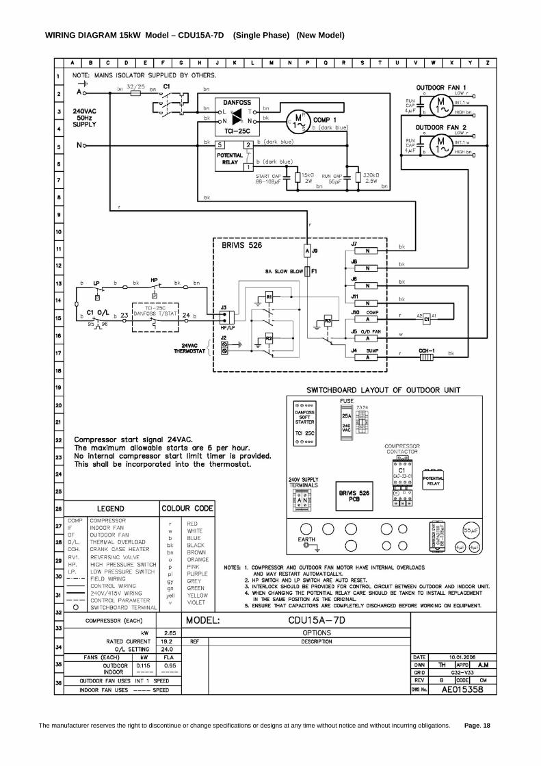
WIRING DIAGRAM 15kW Model – CDU15A-7D (Single Phase) (New Model)
The manufacturer reserves the right to discontinue or change specifications or designs at any time without notice and without incurring obligations. Page. 18
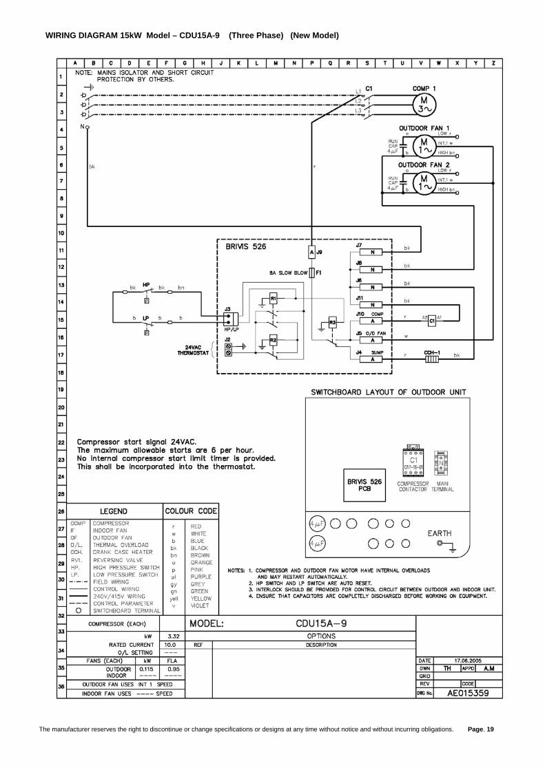
WIRING DIAGRAM 15kW Model – CDU15A-9 (Three Phase) (New Model)
The manufacturer reserves the right to discontinue or change specifications or designs at any time without notice and without incurring obligations. Page. 19

WIRING DIAGRAM 18kW Model – CDU18A-9 (Three Phase) (New Model)
The manufacturer reserves the right to discontinue or change specifications or designs at any time without notice and without incurring obligations. Page. 20

WIRING DIAGRAM 21kW Model – 38CDA21A9 (Three Phase) (New Model)
The manufacturer reserves the right to discontinue or change specifications or designs at any time without notice and without incurring obligations. Page. 21

WIRING CIRCUIT FOR CURRENT BRIVIS 15, 20 & 26kW CLASSIC MODELS WITH ADD-ON COOLING
Y G
R
Electronic Thermostat
W
Refrigeration Compressor Relay
BC-G1
Fan Speed
G W R
EARTH
Rc
Electronic Control Module
WIRING CIRCUIT FOR SUPERSEDED BRIVIS 52, 85, 92 & 120 Mj CLASSIC MODELS WITH ADD-ON COOLING These heaters can be easily identified by the green terminal strip with 6 points, located at the bottom of the electronic control board. These classic units are usually built prior to 18/10/1999. They have a standing pilot and are classed by a mega-joule rating rather than a kilowatt rating.
Y G
Y G
R
RWECT
Heater - Electronic Controller
Electronic Thermostat
Refrigeration Compressor Relay
Add On Cooling Circuit DiagramElectronic Classic Heaters
W
The manufacturer reserves the right to discontinue or change specifications or designs at any time without notice and without incurring obligations. Page. 22

WIRING CIRCUIT FOR PRE- ELECTRONIC BRIVIS HEATERS 85, 92 & 120 Mj CLASSIC MODELS WITH ADD-ON COOLING This diagram shows how add on cooling can be connected to a classic heater built prior to 01/05/1991. These heaters don’t have an electronic control box, just hard wiring.
W RC Y GElectronic Stat
9 8 5
24 Volt Relay
240V
To CompressorRelay
Speed ControlCapacitor
Fan Motor
Earth
BlackBlue
Brown
To Room
Thermostat
24 V
Fan Controller
Remote FanSwitch Tapping(If Required)
KlixonOverheat
Reigniter
Varistor
24 V
2A Fuse
Transformer24V Tapping for Add On
Air-con
240 V
470
Gas Valve
RedundantValve
Flame DetectionSwitch (Buffalo Only)
Earth
240V 50Hz AC
A N
A N E
R
W
Grey
ControlBox
The manufacturer reserves the right to discontinue or change specifications or designs at any time without notice and without incurring obligations. Page. 23

POST INSTALLATION CHECKLIST, COMMISSIONING DATA
& WARRANTY REGISTRATION FORM
ICE SERIES ADD-ON COOLING
(Installer, please complete all sections of this form with the exception of the “customers details” section, then detach this page and the following pages and leave them with the customer).
*WARRANTY WILL ONLY BE VALID UPON RECEIPT OF THIS COMPLETED FORM TO BRIVIS
PRELIMINARY SYSTEM INFORMATION MODEL (Outdoor Unit)
CDU -
SERIAL No. (Outdoor Unit)
MODEL
(Indoor Unit) COU -
SERIAL No. (Indoor Unit)
DATE INSTALLED BY
HEATER MAKE
HEATER MODEL
CUSTOMERS DETAILS (Customer, please complete this section and return completed form to Brivis in the pre-paid envelope provided. Please ensure you understand and have been left your copy of the Warranty and Privacy Notification Statements on pages 26 and 28). Name:
Address:
Postal Address:
State:
Country: Postcode:
Telephone h) b) m)
Email PRE START-UP (Please tick boxes below as each item is completed). VERIFY THAT ALL PACKAGING MATERIALS HAVE BEEN REMOVED FROM UNIT.
REMOVE ALL SHIPPING HOLDDOWN BOLTS AND BRACKETS, AS PER INSTALLATION INSTRUCTIONS.
CHECK THAT CONDENSATE CONNECTION IS INSTALLED, AS PER INSTALLATION INSTRUCTIONS.
CHECK ALL ELECTRICAL CONNECTIONS AND TERMINALS FOR TIGHTNESS.
CHECK THAT INDOOR RETURN AIR FILTER IS CLEAN AND IN PLACE.
VERIFY THAT UNIT INSTALLATION IS LEVEL.
CHECK FANS FOR ALIGNMENT AND NOISE.
The manufacturer reserves the right to discontinue or change specifications or designs at any time without notice and without incurring obligations. Page. 24

The manufacturer reserves the right to discontinue or change specifications or designs at any time without notice and without incurring obligations. Page. 25
OPERATION CHARACTERISTICS (Please record the following data after at least 20 minutes running time). Suction Pressure
kPa Suction Line Temperature
oC Discharge Pressure
kPa Liquid Line Temperature
oC
Superheat K
Subcooling K
Compressor Amps (L1) A
Compressor Amps (L2 for 3 phase) A
Compressor Amps (L3 for 3 phase) A
Indoor coil Air On (Return) Temperature
oC DB Indoor coil Air Off (Supply) Temperature
oC DB
Outdoor air Temperature (Ambient)
oC DB Length of liquid line
m Length of suction line
m Extra refrigerant quantity charged (if any)
kg Supply voltage
V Actual voltage
V

WARRANTY
MODEL (Outdoor Unit)
CDU - SERIAL No. (Outdoor Unit)
MODEL
(Indoor Unit) COU - SERIAL No.
(Indoor Unit)
DATE INSTALLED BY
HEATER MAKE HEATER MODEL
Brivis have a reputation for product quality. Proof of that is our 5 year parts and labour warranty on your Add On Cooling system* from the date of purchase by the purchaser. To claim your warranty, we simply ask that a Brivis Service Technician or an Authorised Service Agent carry out any repairs. Subject to these terms of Warranty, Brivis will repair or replace at its discretion the product or any part of the product that its examination shows to be defective. The Owner/Purchaser must where deemed necessary for safe work practice, pay all costs in respect of making the product accessible for service. Please note a travel charge may apply for service calls beyond a 100km radius from an authorized service agent. This warranty applies to domestic installations; commercial installations are limited to a one year parts and labour warranty. Warranty does not apply in the following circumstances: (a) The cost of routine maintenance as set out on page 26 of these installation instructions. (b) To any product which has been subject of misuse, abuse, negligence or accident. (c) To any product which has been installed in a portable building or structure. (d) To any product, which has been installed, operated or maintained other than in accordance with the written
operating instructions that were supplied with the product. (e) To any product that has been damaged as a result of adverse environmental conditions, eg floods. (f) In respect to any damage to a product or defect in a product where that damage or defect is the normal
degradation of a consumable item such as an air filter. (g) To any ancillary components of an installation such as control wiring, ducting, pipework, grille, register,
diffuser and fabricated or added components. (h) Any product which has been used for any purpose other than artificially cooling or heating the air within a
building or room, so as to provide a comfortable environment for the persons occupying the building or room. (i) Applications where electric/ electronics may be subjected to moisture or chemicals. (j) Where a Brivis coil is matched with a non Brivis condenser and vice versa Trade Practices Act The Purchaser has the benefit of conditions and warranties implied by the Trade Practices Act of 1974 and nothing in these terms is intended to exclude, restrict or modify any statutory obligation of the vendor if that cannot be lawfully effected. * The Add On Cooling system consists of the indoor coil unit and the outdoor condenser only. Note that the heater has separate warranty conditions.
The manufacturer reserves the right to discontinue or change specifications or designs at any time without notice and without incurring obligations. Page. 26

MAINTENANCE AND SERVICE MAINTENANCE To ensure continuing high performance and to minimise the possibility of premature equipment failure, periodic maintenance must be performed on the air conditioning equipment. The units should be inspected at least once each year by a qualified service person. The minimum maintenance requirements for this equipment are as follows: Monthly • Inspect Return Air Filters. Replace throwaway type filters when they become clogged with dust and lint or clean
cleanable type filters monthly. Yearly • Inspect indoor coil, drain pan and condensate drain. Clean when necessary. • Inspect the heater’s fan motor and wheel for cleanliness and alignment. Clean and align the motor assembly
where applicable. • Inspect outdoor coil. Clean when necessary. • Inspect outdoor fans and motors. Ensure that fan blades are clean and adequately balanced. • Inspect the unit cabinet and insulation for damage and corrosion. Repair where necessary. Check for vibration
and excessive noise. Correct where necessary. • Inspect refrigerant tubing for oil accumulations. If oil is detected, leak test refrigerant tubing using an electronic
leak detector or liquid soap solution. • Check refrigerant charge by measurement of superheat and subcooling. Where necessary, adjust charge to
achieve optimum performance. • Check the tightness of electrical connections.
Brivis Add On Cooling Care Program Membership If you would like to join our Brivis Care Program please complete the following information with the warranty form. Would you like to join the Brivis Care Program? Yes No Note: Service maintenance is not covered under warranty and is a chargeable service. All units must have safe and reasonable access and be installed in compliance with the installation instructions supplied with the unit. Some installations may require two service personnel to attend, in accordance with EH & S requirements.
The manufacturer reserves the right to discontinue or change specifications or designs at any time without notice and without incurring obligations. Page. 27

The manufacturer reserves the right to discontinue or change specifications or designs at any time without notice and without incurring obligations. Page. 28
FOR BRIVIS SERVICE Australia Phone: Toll Free 1800 335 094 or local (03) 9264 9477 Fax: 1800 655 465 or local (03) 9264 9499 Address: 61 Malcolm Road, Braeside, Victoria 3195 Call Centre hours: 7:30am – 7:30pm Monday to Friday 8:00am – 2:00pm Saturday After hours calls are answered through the Brivis Message Centre. * Closed some Public Holidays New Zealand Phone: 0800 427 484 or local (04) 526 9167 Fax: (04) 526 9171 Address: P.O. Box 48092 Silverstream, Upper Hutt, Wellington NZ Internet www.brivis.com.au PRIVACY NOTIFICATION STATEMENT Dear Customer, Carrier Australia will be collecting “personal information” from you when you complete your warranty registration form. This information is personal information for the purposes of the Privacy and Personal Information Protection Act 1998. The purpose of collecting this information is to:
� Process your request for us to provide service activities for you � Register your purchase of equipment for warranty � Register your request for a survey/quotation for HVAC goods and services
The intended recipients of this information are:
� Employees of Carrier Australia � Federal and State Governments who may require the information for administration purposes
While the supply of the information by you is voluntary, if you cannot provide or do not wish to provide the information sought, Carrier Australia may be unable to provide the services you request. If you have already provided information but you have changed your mind and do not want the information used, you may make an application for access or amendment for that information not to be used. You have a right of access to, and correction of, the information concerning yourself in accordance with the relevant procedures under the Act. Enquires concerning this matter can be addressed to: The Business Practices Officer Carrier Australia 61 Malcolm Road Braeside VIC 3195