lms100/111/120 laser measurement systems -...
TRANSCRIPT
LMS100/111/120
Laser Measurement Systems
Convenient Measurement Systems
with Double-pulse Technology
O P E R AT I N G I N S T R U C T I O N S

Software version Operating Instructions
LMS100/LMS111/LMS120 Laser Measurement Systems
Software version described
Software access to the LMS is password protected.
The LMS100/LMS111/LMS120 complies with the requirements in the standard on the radiated emissions as defined for class A (industrial environment). It may cause radio interference in residential areas. If radio interference occurs, the person(s) affected may demand that the operator take appropriate action for suppressing interference.
Software/tool Function StatusLMS1xx-XXXX Firmware V 1.2Device description LMS1xxXXXX
Device specific software module for SOPAS ET
V 1.1 or higher
SOPAS ET Configuration software V 02.18 or higher
User level PasswordMaintenance personnel mainAuthorised client client
Copyright
Copyright © 2008SICK AG WaldkirchAuto Ident, Reute PlantNimburger Straße 1179276 ReuteGermany
Trademarks
Windows 2000™, Windows XP™, Windows Vista™ and Internet Explorer™ are registered trademarks of Microsoft Corporation in the USA and other countries.
Acrobat® Reader™ is a trademark of Adobe Systems Incorporated.
Version of the operating instructions
The latest version of these operating instructions can be obtained as PDF at www.sick.com.
2 © SICK AG · Division Auto Ident · Germany · All rights reserved 8012471/SI79/2008-12-05

Operating Instructions
LMS100/LMS111/LMS120
Contents
Table of contents1 About this document .......................................................................................................91.1 Function of this document .......................................................................................... 91.2 Target group ................................................................................................................ 91.3 Depth of information ................................................................................................... 91.4 Symbology used ........................................................................................................102 For your safety .............................................................................................................. 112.1 Authorised personnel ................................................................................................112.2 Correct use ................................................................................................................112.3 General safety notes and protective measures ......................................................122.4 Quick stop and Quick restart ....................................................................................142.5 Environmental protection .........................................................................................143 Product description ...................................................................................................... 163.1 Delivery ......................................................................................................................163.2 Device variants ..........................................................................................................163.3 Special features of the LMS ..................................................................................... 183.4 Controls and status indicators .................................................................................183.5 Operating principle of the LMS .................................................................................203.6 Applications ...............................................................................................................273.7 Measurement of objects ........................................................................................... 273.8 Field application ........................................................................................................333.9 Inputs and outputs ....................................................................................................373.10 Data interfaces ..........................................................................................................383.11 Data communication using messages .................................................................... 403.12 Planning .....................................................................................................................414 Mounting ........................................................................................................................ 444.1 Overview of the mounting steps ...............................................................................444.2 Preparations for mounting ........................................................................................444.3 Mounting steps ..........................................................................................................454.4 Dismanteling the system ..........................................................................................525 Electrical installation ................................................................................................... 535.1 Overview of the installation steps ............................................................................535.2 Connections of the LMS ............................................................................................535.3 Preparing the electrical installation .........................................................................575.4 Perform electrical installation on the LMS ..............................................................586 Commissioning and configuration ............................................................................. 666.1 Overview of the commissioning steps .....................................................................666.2 SOPAS ET configuration software ............................................................................666.3 Establish communication with the LMS ..................................................................676.4 Initial commissioning ................................................................................................686.5 Connection and test measurement .........................................................................707 Maintenance ................................................................................................................. 717.1 Maintenance during operation .................................................................................717.2 Exchanging an LMS ...................................................................................................718 Troubleshooting ............................................................................................................ 728.1 In the event of faults or errors ..................................................................................728.2 Error displays of the LEDs ........................................................................................728.3 Indications of the 7segment display .......................................................................738.4 Detailed error analysis ..............................................................................................73
8012471/SI79/2008-12-05 © SICK AG · Division Auto Ident · Germany · All rights reserved 3

Contents Operating Instructions
LMS100/LMS111/LMS120 Laser Measurement Systems
9 Technical specifications .............................................................................................. 749.1 Data sheet LMS laser measurement system ......................................................... 749.2 Dimensional drawings .............................................................................................. 7910 Annex ............................................................................................................................. 8410.1 Overview of the annexes .......................................................................................... 8410.2 Messages .................................................................................................................. 8410.3 Ordering information .............................................................................................. 10110.4 Glossary ................................................................................................................... 10310.5 EC Declaration of Conformity ................................................................................. 104
4 © SICK AG · Division Auto Ident · Germany · All rights reserved 8012471/SI79/2008-12-05

Operating Instructions
LMS100/LMS111/LMS120
Figures and tables
AbbreviationsATEX Atmosphère explosible = synonym for explosion protection
BCC Block character check
CAN Controller area network = standardised fieldbus system with message-based protocol for exchanging data
CoLa Communication Language = proprietary SOPAS ET communication language (ASCII = CoLaA or binary = CoLaB)
CS Checksum
EEPROM Electrically erasable programmable read-only memory
HTML Hypertext markup language = page description language on the Internet
LED Light Emitting Diode
LMS SICK AG laser measurement system
RAM Random access memory = volatile memory with direct access
ROM Read-only memory (permanent)
SOPAS ET SICK OPEN PORTAL for APPLICATION and SYSTEMS Engineering Tool = configuration software for the configuration of the LMS100/LMS111/LMS120
VdS Verband deutscher Sachversicherer (Association of German insurers)
8012471/SI79/2008-12-05 © SICK AG · Division Auto Ident · Germany · All rights reserved 5
Figures and tables Operating Instructions
LMS100/LMS111/LMS120 Laser Measurement Systems
TablesTab. 1: Target groups of this document .............................................................................. 9
Tab. 2: Authorised personnel .............................................................................................11
Tab. 3: Delivery ...................................................................................................................16
Tab. 4: Device variants .......................................................................................................16
Tab. 5: Special features of the LMS variants ...................................................................18
Tab. 6: Meaning of the LEDs ..............................................................................................19
Tab. 7: Input combination examples .................................................................................34
Tab. 8: Frame for the messages with ASCII coding ..........................................................41
Tab. 9: Frame for the messages with binary coding ........................................................41
Tab. 10: Beam diameter at different distances from the LMS ..........................................43
Tab. 11: Terminal assignment of the LMS100 ...................................................................54
Tab. 12: Pin assignment of the “Ethernet” connection on the LMS100 ..........................54
Tab. 13: Pin assignment of the “Auxiliary interface” connection on the LMS100 ...........55
Tab. 14: Terminal assignment of the LMS120 ...................................................................55
Tab. 15: Pin assignment of the “Ethernet” connection on the LMS120 ..........................56
Tab. 16: Pin assignment of the “Auxiliary interface” connection on the LMS120 ...........56
Tab. 17: Pin assignment of the “Power” connection on the LMS111 ..............................56
Tab. 18: Pin assignment of the “RS232” connection on the LMS111 ............................56
Tab. 19: Pin assignment of the “I/O” connection on the LMS111 ...................................57
Tab. 20: Pin assignment of the “Ethernet” connection on the LMS111 ..........................57
Tab. 21: Pin assignment of the “Auxiliary interface” connection on the LMS111 ...........57
Tab. 22: Maximum cable lengths for the data interfaces ..................................................58
Tab. 23: SOPAS ET default setting .......................................................................................67
Tab. 24: Connect the data interfaces ..................................................................................67
Tab. 25: Passwords ..............................................................................................................69
Tab. 26: Error displays of the LEDs .....................................................................................72
Tab. 27: Indications of the 7segment display ....................................................................73
Tab. 28: Data sheet LMS100/LMS111/LMS120 ..............................................................74
Tab. 29: Variable types .........................................................................................................84
Tab. 30: Hash values of the passwords ..............................................................................93
Tab. 31: Available systems ................................................................................................ 101
Tab. 32: Available accessories ......................................................................................... 101
6 © SICK AG · Division Auto Ident · Germany · All rights reserved 8012471/SI79/2008-12-05
Operating Instructions
LMS100/LMS111/LMS120
Figures and tables
FiguresFig. 1: Laser output aperture of the LMS ........................................................................ 13
Fig. 2: Laser warning label on the LMS ........................................................................... 14
Fig. 3: Device variants ...................................................................................................... 17
Fig. 4: Status indicators .................................................................................................... 19
Fig. 5: Measuring principle of the LMS ........................................................................... 20
Fig. 6: Principle of operation for pulse propagation time measurement ...................... 20
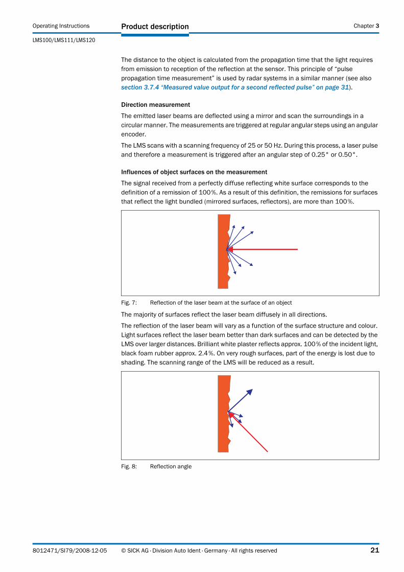
Fig. 7: Reflection of the laser beam at the surface of an object ................................... 21
Fig. 8: Reflection angle ..................................................................................................... 21
Fig. 9: Degree of reflection ............................................................................................... 22
Fig. 10: Mirror surfaces ...................................................................................................... 22
Fig. 11: Object smaller than diameter of the laser beam ................................................ 22
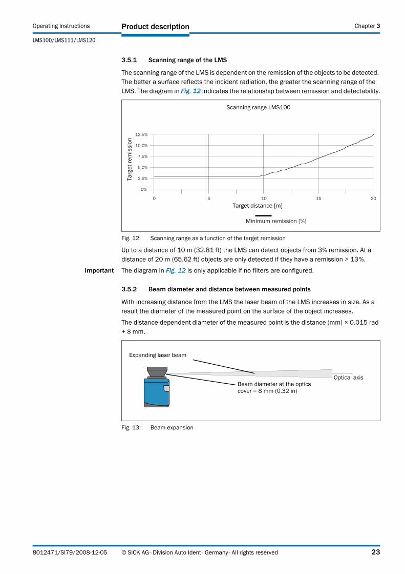
Fig. 12: Scanning range as a function of the target remission ........................................ 23
Fig. 13: Beam expansion .................................................................................................... 23
Fig. 14: Schematic layout of the distance between measured points at different angular resolutions ............................................................................ 24
Fig. 15: Beam diameter and distance between measured points at 0 to 20 m (0 to 65.62 ft) ........................................................................................................ 24
Fig. 16: Minimum object size for detection ....................................................................... 25
Fig. 17: Measured value message request ....................................................................... 29
Fig. 18: Continuous measured value output ..................................................................... 30
Fig. 19: Principle of operation of the measurement of the second reflected pulse ....... 31
Fig. 20: Shading of reflections ........................................................................................... 32
Fig. 21: Principle of the field application ........................................................................... 33
Fig. 22: Protection against tampering due to shading and glare .................................... 35
Fig. 23: Examples of different evaluation field shapes .................................................... 36
Fig. 24: Logical operators for inputs and outputs ............................................................. 38
Fig. 25: Increase in the size of the beam and safety supplement .................................. 42
Fig. 26: Direct mounting ..................................................................................................... 46
Fig. 27: Mounting with mounting kit 1a ............................................................................. 47
Fig. 28: Mounting with mounting kit 1b ............................................................................ 47
Fig. 29: Mounting with mounting kit 2 and 3 .................................................................... 48
Fig. 30: Weather protection hood 190° ............................................................................ 49
Fig. 31: Weather protection hood 270° ............................................................................ 49
Fig. 32: Mounting kit for the weather protection hood ..................................................... 50
Fig. 33: Quick-action mounting kit for the weather protection hood ............................... 50
Fig. 34: Placement of two LMS opposed to each other ................................................... 51
Fig. 35: Crosswise placement of two LMS ........................................................................ 51
Fig. 36: Placement of two LMS with parallel offset .......................................................... 51
Fig. 37: Placement of two LMS with parallel offset, one of these upside down ............. 51
Fig. 38: Placement of two LMS upside down, parallel offset ........................................... 52
Fig. 39: Placement of two LMS with parallel offset, one of these upside down ............. 52
8012471/SI79/2008-12-05 © SICK AG · Division Auto Ident · Germany · All rights reserved 7
Figures and tables Operating Instructions
LMS100/LMS111/LMS120 Laser Measurement Systems
Fig. 40: LMS100/LMS111/LMS120: RS232 connection at the auxiliary interface .....59
Fig. 41: LMS100/LMS111/LMS120: Ethernet connection using the Ethernet cable ...59
Fig. 42: LMS111: connection of the voltage supply ..........................................................60
Fig. 43: LMS111: “RS232” connection ............................................................................61
Fig. 44: LMS111: “I/O” connection ....................................................................................61
Fig. 45: Connecting digital inputs as non-floating .............................................................61
Fig. 46: Connecting digital inputs as floating ....................................................................62
Fig. 47: Wiring encoder inputs ............................................................................................62
Fig. 48: Connection of the outputs to a PLC, non-floating (active high) ..........................63
Fig. 49: Connection of the outputs to a PLC, non-floating (active low) ............................63
Fig. 50: Connection of the outputs to a PLC, floating (active high) ..................................63
Fig. 51: Connection of the outputs to a PLC, floating (active low) ...................................63
Fig. 52: Connection to an object protection system .........................................................64
Fig. 53: Connection to an object protection system, resistance monitored ....................64
Fig. 54: Wiring of the CAN interface ...................................................................................64
Fig. 55: Wiring the RS232 interface ..................................................................................65
Fig. 56: Principle of data storage .......................................................................................69
Fig. 57: Dimensional drawing LMS100/LMS120 .............................................................79
Fig. 58: Dimensional drawing LMS111 ..............................................................................80
Fig. 59: Dimensional drawing, mounting kit 1a (mm) .......................................................81
Fig. 60: Dimensional drawing, mounting kit 1b (mm) .......................................................81
Fig. 61: Dimensional drawing, mounting kit 2 (mm) .........................................................82
Fig. 62: Dimensional drawing, mounting kit 3 (mm) .........................................................82
Fig. 63: Dimensional drawing weather protection hood 190° .........................................83
Fig. 64: Dimensional drawing weather protection hood 270° .........................................83
Fig. 65: Illustration containing the EC Declaration of Conformity ................................. 104
8 © SICK AG · Division Auto Ident · Germany · All rights reserved 8012471/SI79/2008-12-05

Operating Instructions
LMS100/LMS111/LMS120
About this document Chapter 1
1 About this document
Please read this chapter carefully before working with this documentation and the LMS100/LMS111/LMS120 laser measurement system.
1.1 Function of this document
These operating instructions are designed to address the technical personnel in regards to safe mounting, electrical installation, configuration, commissioning and maintenance of the following laser measurement system variants:
• LMS100 (indoor)
• LMS111 (outdoor)
• LMS120 (indoor, for object protection systems)
Important In the following the variants are termed “LMS” for short, except in cases where exact differentiation is necessary.
1.2 Target group
The intended audience for this document is people in the following positions:
1.3 Depth of information
These operating instructions contain the following information on the LMS:
• product description
• mounting
• electrical installation
• commissioning and configuration
• maintenance
• fault, error diagnosis and troubleshooting
• ordering information
• conformity and approval
Planning and using laser measurement systems such as the LMS also require specific technical skills which are not detailed in this documentation.
In addition, an online help is available in the SOPAS ET configuration software supplied; this help provides information on the usage of the software user interface, as well as on the configuration of the LMS.
Further information on the LMS is available from SICK AG, Division Auto Ident, and in the Internet at www.sick.com.
Activities Target groupMounting, electrical installation, maintenance and replacement
Factory electricians and service engineers
Commissioning, operation and configuration
Technicians and engineers
Tab. 1: Target groups of this document
8012471/SI79/2008-12-05 © SICK AG · Division Auto Ident · Germany · All rights reserved 9
About this document Operating Instructions
LMS100/LMS111/LMS120 Laser Measurement Systems
Chapter 1
1.4 Symbology used
Recommendation Recommendations are designed to give you assistance in the decision-making process with respect to a certain function or a technical measure.
Important Sections marked “Important” provide information about special features of the device.
Explanation Explanations provide background knowledge on technical relationships.
MENU COMMAND This typeface indicates a term in the SOPAS ET user interface.
Terminal output This typeface indicates messages that the LMS outputs via its interfaces.
Take action … Instructions for taking action are shown by an arrow. Read carefully and follow the instructions for action.
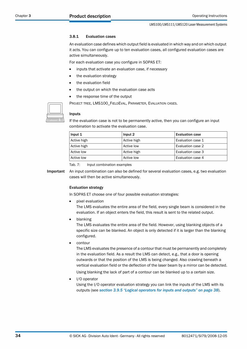
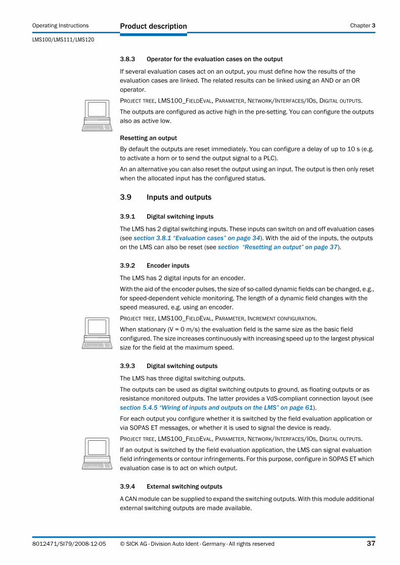
This symbol refers to additionally available documentation.
Software notes show where you can make the appropriate settings and adjustments in the SOPAS ET configuration software.
Note!
A note indicates potential hazards that could involve damage or degradation of the functionality of the LMS or other devices.
Warning!
A warning indicates an actual or potential hazard. They are designed to help you to prevent accidents.
The safety symbol beside the warning indicates the nature of the risk of accident, e.g. due to electricity. The warning category (DANGER, WARNING, CAUTION) indicates the severity of the hazard.
Read carefully and follow the warning notices!
10 © SICK AG · Division Auto Ident · Germany · All rights reserved 8012471/SI79/2008-12-05
Operating Instructions
LMS100/LMS111/LMS120
For your safety Chapter 2
2 For your safety
This chapter deals with your own safety and the safety of the equipment operators.
Please read this chapter carefully before working with the LMS.
2.1 Authorised personnel
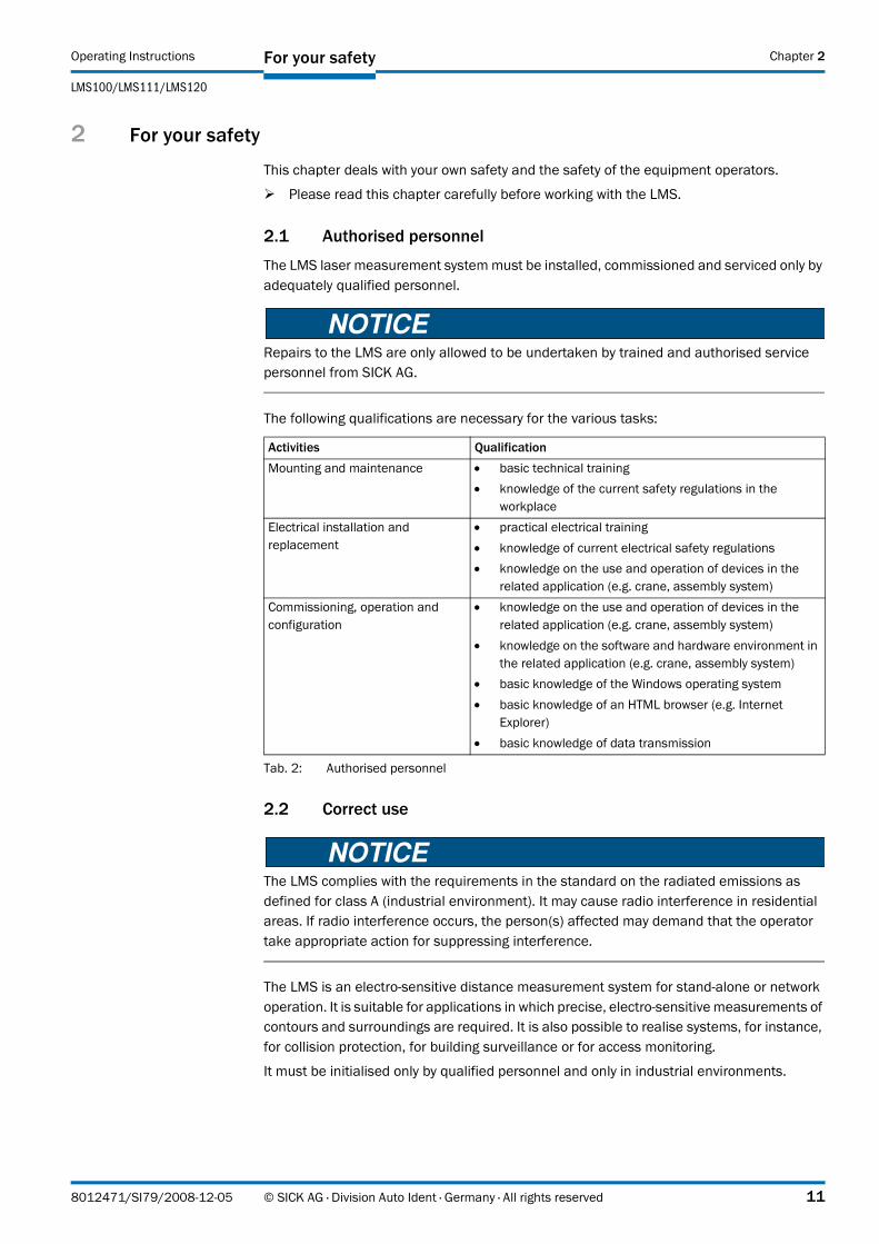
The LMS laser measurement system must be installed, commissioned and serviced only by adequately qualified personnel.
Repairs to the LMS are only allowed to be undertaken by trained and authorised service personnel from SICK AG.
The following qualifications are necessary for the various tasks:
2.2 Correct use
The LMS complies with the requirements in the standard on the radiated emissions as defined for class A (industrial environment). It may cause radio interference in residential areas. If radio interference occurs, the person(s) affected may demand that the operator take appropriate action for suppressing interference.
The LMS is an electro-sensitive distance measurement system for stand-alone or network operation. It is suitable for applications in which precise, electro-sensitive measurements of contours and surroundings are required. It is also possible to realise systems, for instance, for collision protection, for building surveillance or for access monitoring.
It must be initialised only by qualified personnel and only in industrial environments.
Activities QualificationMounting and maintenance • basic technical training
• knowledge of the current safety regulations in the workplace
Electrical installation and replacement
• practical electrical training• knowledge of current electrical safety regulations• knowledge on the use and operation of devices in the
related application (e.g. crane, assembly system)Commissioning, operation and configuration
• knowledge on the use and operation of devices in the related application (e.g. crane, assembly system)
• knowledge on the software and hardware environment in the related application (e.g. crane, assembly system)
• basic knowledge of the Windows operating system• basic knowledge of an HTML browser (e.g. Internet
Explorer)• basic knowledge of data transmission
Tab. 2: Authorised personnel
8012471/SI79/2008-12-05 © SICK AG · Division Auto Ident · Germany · All rights reserved 11
For your safety Operating Instructions
LMS100/LMS111/LMS120 Laser Measurement Systems
Chapter 2
In case of any other usage as well as in case of modifications to the LMS, e.g. due to opening the housing during mounting and electrical installation, or to the SICK software, any claims against SICK AG under the warranty will be rendered void.
The LMS is only allowed to be operated in the ambient temperature range allowed (see section 9.1 “Data sheet LMS laser measurement system” on page 74).
2.3 General safety notes and protective measures
Safety notes
Please observe the following items in order to ensure the correct and safe use of the LMS.
• The notices in these operating instructions (e.g. on use, mounting, installation or integration into the existing machine controller) must be observed.
• When operating the LMS, the national, local and statutory rules and regulations must be observed.
• National/international rules and regulations apply to the installation, commissioning, use and periodic technical inspections of the laser measurement system, in particular:
– the work safety regulations/safety rules– other relevant health and safety regulations
• Manufacturers and operators of the system on which the LMS is installed are responsible for obtaining and observing all applicable safety regulations and rules.
• The tests must be carried out by specialist personnel or specially qualified and authorised personnel and must be recorded and documented to ensure that the tests can be reconstructed and retraced at any time.
• The operating instructions must be made available to the operator of the system where the LMS is fitted. The operator of the system is to be instructed in the use of the device by specialist personnel and must be instructed to read the operating instructions.
• The LMS is not a device for the protection of people in the context of the related safety standards for machinery.
• The LMS is intended exclusively for use in industrial environments. When used in residential areas, the device can cause radio interferences.
12 © SICK AG · Division Auto Ident · Germany · All rights reserved 8012471/SI79/2008-12-05
Operating Instructions
LMS100/LMS111/LMS120
For your safety Chapter 2
2.3.1 Electrical installation work
• Only authorised personnel are allowed to perform the electrical installation work.
• Only make and disconnect electrical connections when the device is electrically isolated.
• Select and implement wire cross-sections and their correct fuse protection as per the applicable standards.
Do not open the housing.
Observe the current safety regulations when working on electrical systems.
2.3.2 Laser radiation from the laser measurement system
Laser radiation!
The LMS corresponds to laser class 1 (eye safe) as per EN 60825-1 (for publication date see laser warning label on the device). Complies with 21 CFR 1040.10 with the exception of the deviations as per Laser Notice No. 50, July 26, 2001. The laser beam cannot be seen with the human eye.
• Incorrect usage can result in hazardous exposure to laser radiation.
Do not open the housing (opening the housing will not switch off the laser).
Pay attention to the laser safety regulations as per IEC 608251 (latest version).
Important No maintenance is necessary to ensure compliance with laser class 1.
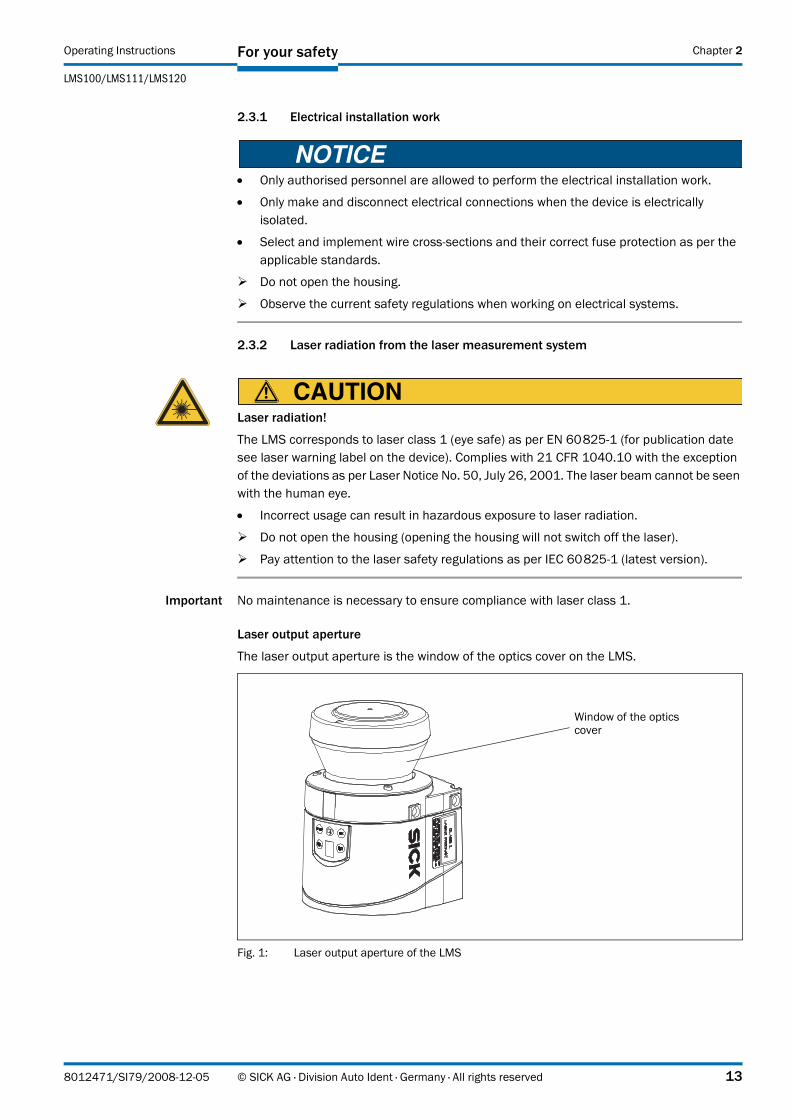
Laser output aperture
The laser output aperture is the window of the optics cover on the LMS.
Fig. 1: Laser output aperture of the LMS
Window of the optics cover
8012471/SI79/2008-12-05 © SICK AG · Division Auto Ident · Germany · All rights reserved 13
For your safety Operating Instructions
LMS100/LMS111/LMS120 Laser Measurement Systems
Chapter 2
Laser power
The laser operates at a wavelength λ = 905 nm (invisible infrared light). The radiation emitted in normal operation is not harmful to the eyes and human skin.
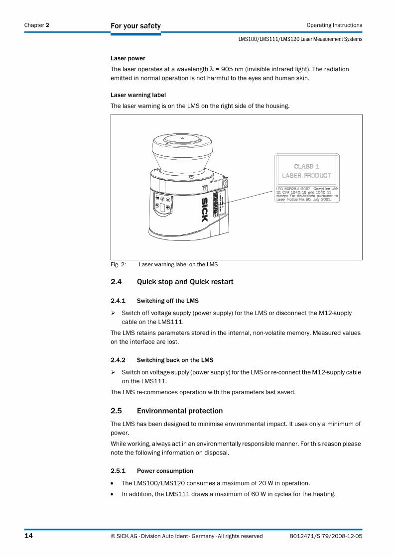
Laser warning label
The laser warning is on the LMS on the right side of the housing.
Fig. 2: Laser warning label on the LMS
2.4 Quick stop and Quick restart
2.4.1 Switching off the LMS
Switch off voltage supply (power supply) for the LMS or disconnect the M12-supply cable on the LMS111.
The LMS retains parameters stored in the internal, non-volatile memory. Measured values on the interface are lost.
2.4.2 Switching back on the LMS
Switch on voltage supply (power supply) for the LMS or re-connect the M12-supply cable on the LMS111.
The LMS re-commences operation with the parameters last saved.
2.5 Environmental protection
The LMS has been designed to minimise environmental impact. It uses only a minimum of power.
While working, always act in an environmentally responsible manner. For this reason please note the following information on disposal.
2.5.1 Power consumption
• The LMS100/LMS120 consumes a maximum of 20 W in operation.
• In addition, the LMS111 draws a maximum of 60 W in cycles for the heating.
14 © SICK AG · Division Auto Ident · Germany · All rights reserved 8012471/SI79/2008-12-05

Operating Instructions
LMS100/LMS111/LMS120
For your safety Chapter 2
2.5.2 Disposal after final de-commissioning
Always dispose of unserviceable or irreparable devices in compliance with local/national rules and regulations on waste disposal.
Dispose of all electronic assemblies as hazardous waste. The electronic assemblies are straightforward to dismantle.
Important SICK AG does not accept unusable or irreparable devices that are returned.
8012471/SI79/2008-12-05 © SICK AG · Division Auto Ident · Germany · All rights reserved 15

Product description Operating Instructions
LMS100/LMS111/LMS120 Laser Measurement Systems
Chapter 3
3 Product description
This chapter provides information on the special features and properties of the LMS laser measurement system. It describes the construction and the operating principle of the device, in particular the different operating modes.
Please read this chapter before mounting, installing and commissioning the device.
3.1 Delivery
The LMS delivery includes the following components:
Section 10.3 “Ordering information” on page 101 provides an overview of the systems available and the accessories available.
3.1.1 Contents of the CD-ROM
• SOPAS ET configuration software
• operating instructions “LMS100/LMS111/LMS120 Laser measurement system” in German and English as PDF
• freely available software “Adobe Acrobat® Reader™”
The latest versions of the publications and programs included on the CDROM are also available for download at www.sick.com.
3.2 Device variants
Quantity Components Comment1 An LMS laser measurement system LMS100 or LMS111 or LMS120,
depending on order1 Device instructions with electrical circuit
diagram for getting startedIs included in the LMS packaging
1 CDROM “Manuals & Software Auto Ident” Contents see 3.1.1
Tab. 3: Delivery
Type Special features Heating Enclosure ratingLMS100 Indoor variant Without IP 65LMS111 Outdoor variant With IP 67LMS120 Indoor variant, optimised for usage in
object protection systemsWithout IP 65
Tab. 4: Device variants
16 © SICK AG · Division Auto Ident · Germany · All rights reserved 8012471/SI79/2008-12-05
Operating Instructions
LMS100/LMS111/LMS120
Product description Chapter 3
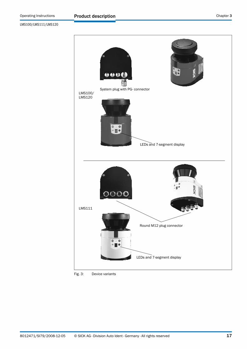
Fig. 3: Device variants
LMS100/LMS120
LMS111
System plug with PG connector
Round M12 plug connector
LEDs and 7segment display
LEDs and 7segment display
8012471/SI79/2008-12-05 © SICK AG · Division Auto Ident · Germany · All rights reserved 17
Product description Operating Instructions
LMS100/LMS111/LMS120 Laser Measurement Systems
Chapter 3
3.3 Special features of the LMS
3.4 Controls and status indicators
3.4.1 User interface
In normal operation the laser measurement system operates fully automatically without the intervention of an operator.
The interactive configuration is carried out using the provided SOPAS ET configuration software. The software used for this purpose runs on a PC that is connected to the LMS via one of the interfaces.
Use the graphic scan view in SOPAS ET to verify the generated measured values and to verify the measurement area online. During this process, note that the field evaluation monitor cannot display the data in real-time and therefore does not display all measured values.
Variant Special featuresAll • field of view maximum 270°
• scanning range up to 20 m (65.62 ft) with 13% object remission(18 m (59.05 ft) with 10% object remission)
• resolution of the angular step width: 0.25/0.50°• rotation frequency 25/50 Hz• flexible system configurations• configuration/measured value request using messages (command
strings)• data interfaces CAN, Ethernet, RS232
Measured value output (raw data)• electro-sensitive, active measurement technique• measurement of objects with almost any shape• measured value output for a second reflection pulse (e.g. in rain or on
measurement through a window)
Integrated field application• 10 configurable evaluation fields• monitoring of the evaluation field contours• switching of the evaluation fields using digital inputs • encoder inputs• additional output of the evaluation field (unoccupied or infringed) via
digital outputs or messagesLMS100 • housing with protection class IP 65LMS111 • outdoor housing with protection class IP 67LMS120 • housing with protection class IP 65
• optimised for usage in object protection systems• sabotage contacts
Tab. 5: Special features of the LMS variants
18 © SICK AG · Division Auto Ident · Germany · All rights reserved 8012471/SI79/2008-12-05

Operating Instructions
LMS100/LMS111/LMS120
Product description Chapter 3
3.4.2 Status indicators
The LEDs and the 7segment display indicate the operational status of the LMS.
Fig. 4: Status indicators
Important • On the LMS, along with the standard displays described below, the indication functions of the LEDs and the 7segment display can be configured in SOPAS ET.
PROJECT TREE, LMS100_FIELDEVAL, PARAMETER, NETWORK/INTERFACES/IOS, DISPLAY.
• On the LMS120 it is important that you disable the status indicators in SOPAS ET after configuration so that device is not recognisable as part of an object protection system.
LEDs
Further information see section 8.2 “Error displays of the LEDs” on page 72.
7segment display
Used for diagnostics on occurring errors or malfunctions (see section 8.3 “Indications of the 7segment display” on page 73).
Display Possible cause
LMS in operation, no evaluation field is signalling an event
LMS in operation, at least one evaluation field is signalling an event
Optics cover contaminated
Switching output OUT1 switched (see section 3.8.3 “Operator for the evaluation cases on the output” on page 37)
Switching output OUT2 switched (see section 3.8.3 “Operator for the evaluation cases on the output” on page 37)
Tab. 6: Meaning of the LEDs
8012471/SI79/2008-12-05 © SICK AG · Division Auto Ident · Germany · All rights reserved 19
Product description Operating Instructions
LMS100/LMS111/LMS120 Laser Measurement Systems
Chapter 3
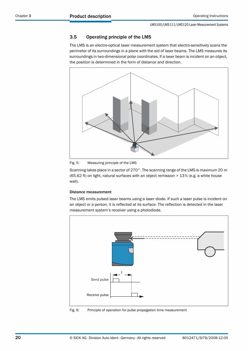
3.5 Operating principle of the LMS
The LMS is an electro-optical laser measurement system that electro-sensitively scans the perimeter of its surroundings in a plane with the aid of laser beams. The LMS measures its surroundings in two-dimensional polar coordinates. If a laser beam is incident on an object, the position is determined in the form of distance and direction.
Fig. 5: Measuring principle of the LMS
Scanning takes place in a sector of 270°. The scanning range of the LMS is maximum 20 m (65.62 ft) on light, natural surfaces with an object remission > 13% (e.g. a white house wall).
Distance measurement
The LMS emits pulsed laser beams using a laser diode. If such a laser pulse is incident on an object or a person, it is reflected at its surface. The reflection is detected in the laser measurement system’s receiver using a photodiode.
Fig. 6: Principle of operation for pulse propagation time measurement
Send pulse
Receive pulse
t
20 © SICK AG · Division Auto Ident · Germany · All rights reserved 8012471/SI79/2008-12-05
Operating Instructions
LMS100/LMS111/LMS120
Product description Chapter 3
The distance to the object is calculated from the propagation time that the light requires from emission to reception of the reflection at the sensor. This principle of “pulse propagation time measurement” is used by radar systems in a similar manner (see also section 3.7.4 “Measured value output for a second reflected pulse” on page 31).
Direction measurement
The emitted laser beams are deflected using a mirror and scan the surroundings in a circular manner. The measurements are triggered at regular angular steps using an angular encoder.
The LMS scans with a scanning frequency of 25 or 50 Hz. During this process, a laser pulse and therefore a measurement is triggered after an angular step of 0.25° or 0.50°.
Influences of object surfaces on the measurement
The signal received from a perfectly diffuse reflecting white surface corresponds to the definition of a remission of 100%. As a result of this definition, the remissions for surfaces that reflect the light bundled (mirrored surfaces, reflectors), are more than 100%.
Fig. 7: Reflection of the laser beam at the surface of an object
The majority of surfaces reflect the laser beam diffusely in all directions.
The reflection of the laser beam will vary as a function of the surface structure and colour. Light surfaces reflect the laser beam better than dark surfaces and can be detected by the LMS over larger distances. Brilliant white plaster reflects approx. 100% of the incident light, black foam rubber approx. 2.4%. On very rough surfaces, part of the energy is lost due to shading. The scanning range of the LMS will be reduced as a result.
Fig. 8: Reflection angle
8012471/SI79/2008-12-05 © SICK AG · Division Auto Ident · Germany · All rights reserved 21

Product description Operating Instructions
LMS100/LMS111/LMS120 Laser Measurement Systems
Chapter 3
The reflection angle is the same as the angle of incidence. If the laser beam is incident perpendicularly on a surface, the energy is optimally reflected (Fig. 7 on page 21). If the beam is incident at an angle, a corresponding energy and scanning range loss is incurred (Fig. 8 on page 21).
Fig. 9: Degree of reflection
If the reflected energy returned is over 100% (basis: Kodak standard) the incident beam is not reflected diffusely in all directions, but is reflected in a specific direction. As a result a large portion of the energy emitted can be received by the laser distance measurement device. Plastic reflectors (“cats’ eyes”), reflective tape and triple prisms have these properties.
Fig. 10: Mirror surfaces
At mirror surfaces the laser beam is almost entirely deflected (Fig. 10 on page 22).
Instead of the surface of the mirror, it is possible that the object on which the deflected laser beam is incident may be detected.
Fig. 11: Object smaller than diameter of the laser beam
Objects that are smaller than the diameter of the laser beam cannot reflect all the energy of the laser light (Fig. 11 on page 22). The energy in the portion of the laser light that is not reflected is lost. This means that the scanning range is less than would be possible theoretically based on the surface of the object.
22 © SICK AG · Division Auto Ident · Germany · All rights reserved 8012471/SI79/2008-12-05
Operating Instructions
LMS100/LMS111/LMS120
Product description Chapter 3
3.5.1 Scanning range of the LMS
The scanning range of the LMS is dependent on the remission of the objects to be detected. The better a surface reflects the incident radiation, the greater the scanning range of the LMS. The diagram in Fig. 12 indicates the relationship between remission and detectability.
Fig. 12: Scanning range as a function of the target remission
Up to a distance of 10 m (32.81 ft) the LMS can detect objects from 3% remission. At a distance of 20 m (65.62 ft) objects are only detected if they have a remission > 13%.
Important The diagram in Fig. 12 is only applicable if no filters are configured.
3.5.2 Beam diameter and distance between measured points
With increasing distance from the LMS the laser beam of the LMS increases in size. As a result the diameter of the measured point on the surface of the object increases.
The distance-dependent diameter of the measured point is the distance (mm) × 0.015 rad + 8 mm.
Fig. 13: Beam expansion
Minimum remission [%]
Scanning range LMS100
Targ
etre
mis
sion
Target distance [m]
Optical axis
Expanding laser beam
Beam diameter at the optics cover = 8 mm (0.32 in)
8012471/SI79/2008-12-05 © SICK AG · Division Auto Ident · Germany · All rights reserved 23

Product description Operating Instructions
LMS100/LMS111/LMS120 Laser Measurement Systems
Chapter 3
With increasing distance from the LMS, the distance between the individual measured points also increases. The distance between the measured points is also dependent on the angular resolution configured. With a coarser resolution, the distance is larger, with a finer resolution the distance is smaller. The distance-dependent spacing between the measured points is the tangent of the angular resolution × distance
Fig. 14: Schematic layout of the distance between measured points at different angular resolutions
The diagram in Fig. 15 shows the beam diameter and the measured point spacing as a function of the distance from the LMS.
Important The beam diameter is always greater than the measured point spacing. As a result full scanning without gaps is ensured.
Fig. 15: Beam diameter and distance between measured points at 0 to 20 m (0 to 65.62 ft)
Scan with 0.50°angular resolution
Scan with 0.25°angular resolution
Measured point
Beam diameter
0
Distance in m (ft)
Size
inm
m(in
)
15 20
0
100
400
200 0.5° angle resolution
0.25° angle resolution
Beam diameter
Distance between measured 10
300
5
24 © SICK AG · Division Auto Ident · Germany · All rights reserved 8012471/SI79/2008-12-05

Operating Instructions
LMS100/LMS111/LMS120
Product description Chapter 3
Example for angular resolution 0.25° in Fig. 15
Distance 10 m (32.81 ft)
Distance intersection point 10 m (32.81 ft) gives a distance between the measured points of approx. 40 mm (1.58 in)
Distance intersection point 10 m (32.81 ft) with the characteristic curve for the beam diameter gives a beam size of approx. 170 mm (6.70 in)
Example for angular resolution 0.50° in Fig. 15
Distance 20 m (65.62 ft)
Distance intersection point 20 m (65.62 ft) gives a distance between the measured points of approx. 180 mm (7.09 in)
Distance intersection point 20 m (65.62 ft) with the characteristic curve for beam diameter gives a beam size of approx. 310 mm (12.21 in)
3.5.3 Minimum object size
To reliably detect an object, a laser beam must be fully incident on it once. If the beam is partially incident, less energy will be reflected by an object than necessary in somecircumstances (see Fig. 11 on page 22).
An object is only reliably fully seen if it is at least as large as the measured point spacing plus the beam diameter.
Fig. 16: Minimum object size for detection
In the example in Fig. 16, the beam is fully incident on the object at least once during each scan. It will therefore be reliably detected if it has the necessary remission.
How to calculate the minimum object size:
Beam diameter + distance between the measured points = minimum object size
For beam diameter and measured point spacing as a function of the distance from the LMS see the diagram in Fig. 15.
Important • In particular on the usage of the LMS for measured value output, it is necessary for a reliable measurement that the beam is incident on the object several times. The example shows the minimum size of an object. For a reliable measurement it is important that the beam is incident on the object several times. Therefore an object should be either larger than the minimum object size or the LMS as well as the object should not move.
Scan 1
Scan 2
Scan 3
Beam diameter
Distance between measured points
8012471/SI79/2008-12-05 © SICK AG · Division Auto Ident · Germany · All rights reserved 25
Product description Operating Instructions
LMS100/LMS111/LMS120 Laser Measurement Systems
Chapter 3
3.5.4 Contamination measurement
The LMS has an optics cover for protection. This optics cover can become contaminated. The laser beam radiation emitted and received is reduced by the contamination. As a result scanned objects are perceived with a lower remission than they actually have, or no longer measured at all from a certain level of contamination.
For this reason the contamination is measured continuously while the device is in operation. For a certain level of contamination, first a contamination warning is output; if the contamination becomes worse, a contamination error is output and the LMS stops taking measurements.
Depending on the application in which the LMS is used, you can choose between various strategies for the contamination measurement.
PROJECT TREE, LMS100_FIELDEVAL, PARAMETER, CONTAMINATION MEASUREMENT.
• inactiveNo contamination measurement
• highly availableContamination warning and contamination error are only output on even contamination of the optics cover.
• availableContamination warning and contamination error are only output on partial contamination of the optics cover.
• sensitive Contamination warning and contamination error are output even with isolated contamination.
Recommendation The cleaner the application environment, the lower you can set the sensitivity for the contamination measurement. The more exact the measured result must be, the higher you should set the sensitivity of the contamination measurement.
Contamination warning and contamination error are indicated on the LEDs on the LMS (see section 8.2 “Error displays of the LEDs” on page 72). You can also read these states using messages (see section 10.2.6 “Read contamination level” on page 92 and section 10.2.3 “Read scan data” on page 87).
A contamination error is also signalled on a digital or external output if this output is configured for the status “Device Ready” (see section 3.9.3 “Digital switching outputs” on page 37).
Important If you use the “Contour monitoring with blanking” strategy (see section “Evaluation strategy” on page 34) in the field evaluation application, the contamination measurement should be configured as inactive. If the contamination measurement is active, erroneous detections of contour infringements may occur.
26 © SICK AG · Division Auto Ident · Germany · All rights reserved 8012471/SI79/2008-12-05

Operating Instructions
LMS100/LMS111/LMS120
Product description Chapter 3
3.6 Applications
In principle the LMS can be used for two purposes:
• for the measurement of objects (see 3.7 on page 27)
• for the detection of objects with evaluation fields (see 3.8 on page 33)
Therefore, the possible applications are very wide-ranging. In particular the following can be stated:
• container loading/handling
• traffic/transport
• robots
• object protection (low false alarm rate)
3.7 Measurement of objects
3.7.1 Basic parameters
The LMS scans with a scanning frequency of 25 or 50 Hz or with an angular resolution of 0.25° or 0.50°. At a higher scanning frequency or a finer angular resolution the LMS supplies more measured values.
PROJECT TREE, LMS100_FIELDEVAL, PARAMETER, BASIC PARAMETERS, areas CURRENT CONFIGURATION and NEW CONFIGURATION.
Important • The LMS outputs the data after the start of the measurement using the same interface over which the measured values were requested.
• It is only possible to output all measured values of a scan in real-time using the Ethernet interface.
In case of an error, the measured value output is stopped immediately and an error code output that can be evaluated by the application connected. The error code can also be queried via SOPAS ET from the LMS (see section 8.4 “Detailed error analysis” on page 73).
3.7.2 Filter
The LMS has digital filters for the pre-processing and optimisation of the measured distance values.
You can configure either a fog filter, a hardware blanking window, an npulseto1pulse filter or a filter for interference suppression.
PROJECT TREE, LMS100_FIELDEVAL, PARAMETER, FILTER.
Fog filter
The fog filter suppresses possible glare due to fog. The LMS becomes less sensitive in the near range (up to approx. 4 m (13.12 ft)) with the fog filter.
Hardware blanking window
Using the blanking window an area in front of the LMS is completely blanked. As a result the LMS only supplies measured values from a configured distance. You can configure a blanking window from 1 to 15 m (3.28 to 49.21 ft).
8012471/SI79/2008-12-05 © SICK AG · Division Auto Ident · Germany · All rights reserved 27
Product description Operating Instructions
LMS100/LMS111/LMS120 Laser Measurement Systems
Chapter 3
N-pulse-to-1-pulse filter
If two pulses are reflected by two objects during a measurement (incident on drops of rain or edges etc.), the filter initially filters out the first reflected pulse (see section 3.7.4 “Measured value output for a second reflected pulse” on page 31).
Particle filter
Important The particle filter is an application filter, it acts on the field application, not on the measured value output.
The particle filter can be used in dusty surroundings or in case of rain or snow to filter out interference due to particles of dust, rain drops, snow flakes etc.
Mean filter
The mean filter acts on the measured value output, not on the field application. If the mean filter is active, the mean is formed from the configured number of scans and then output.
The mean filter reduces the scan data output (not a smoothing mean).
3.7.3 Measured value output
For the measured value output, the LMS supplies measured values to one of the interfaces. It is prerequisite for this data output that the LMS is in the measurement mode. There are two ways you can start the measurement mode:
• start via SOPAS ET
PROJECT TREE, LMS100_FIELDEVAL, PARAMETER, BASIC PARAMETERS, area MEASUREMENT.
• start via message (see section 10.2.1 “Start measurement” on page 85)
Recommendation After the measurement mode is started the LMS needs a little time to reach the status “Ready for measurement”. You should therefore query the status of the LMS using the sRN STlms message (see section 10.2.2 “Query status” on page 86).
Then request measured data by using a message on the interface from which you want to receive measured data. There are two possible ways of doing this:
• Exactly one measured value message can be requested using the sRN LMDscandata message — the last scan measured is transferred (see section 10.2.3 “Read scan data” on page 87).
• Measured data can be continuously requested using the sEN LMDscandata message — measured data are then transferred until the measured value output is stopped using the sEN LMDscandata message (see section 10.2.3 “Read scan data” on page 87).
28 © SICK AG · Division Auto Ident · Germany · All rights reserved 8012471/SI79/2008-12-05

Operating Instructions
LMS100/LMS111/LMS120
Product description Chapter 3
Example of single measured value output
Fig. 17: Measured value message request
1. Start measurement
Request
<STX>sMN LMCstartmeas<ETX>
LMS answer
<STX>sAN LMCstartmeas 0<ETX>
2. Query measuring status
You must query the status until status 7 (that is ready to measure) is achieved in the reply.
Request
<STX>sRN STlms<ETX>
LMS answer
<STX>sRA STlms 7 0 8 00:00:00 8 01.0 1.06 0 0 0<ETX>
Important If the status is less than 7, you must send the request again.
Start the output of measured values for a single scan
Request
<STX>sRN LMDscandata<ETX>
LMS answer
<STX>sRA LMDscandata [contents see section 10.2.3 “Read scan data” on page 87]<ETX>
Measured value message output
Measured value request
8012471/SI79/2008-12-05 © SICK AG · Division Auto Ident · Germany · All rights reserved 29

Product description Operating Instructions
LMS100/LMS111/LMS120 Laser Measurement Systems
Chapter 3
Example of continuous measured value output
Fig. 18: Continuous measured value output
Recommendation If you are not certain that the scan data can be processed at the speed at which they are output by the LMS, you should only request the scan data for a single scan. The scan counter in the measured value output can be used as an indication that processing is too slow (see section 10.2.3 “Read scan data” on page 87).
1. Start measurement
Request
<STX>sMN LMCstartmeas<ETX>
LMS answer
<STX>sAN LMCstartmeas 0<ETX>
2. Query measuring status
You must query the status until status 7 (that is ready to measure) is achieved in the reply.
Request
<STX>sRN STlms<ETX>
LMS answer
<STX>sRA STlms 7 0 8 00:00:00 8 01.0 1.06 0 0 0<ETX>
If the status is less than 7, you must send the request again.
3. Start continuous measured value output
The scan data are output until measured value output is ended.
Request
<STX>sEN LMDscandata 1<ETX>
LMS confirmation
<STX>sEA LMDscandata 1<ETX>
LMS answer
<STX>sSN LMDscandata [contents see section 10.2.3 “Read scan data” on page 87]<ETX>
4. Stop continuous measured value output
Request
<STX>sEN LMDscandata 0<ETX>
Output of the measured value messages
Measured value request
Stop the output
30 © SICK AG · Division Auto Ident · Germany · All rights reserved 8012471/SI79/2008-12-05

Operating Instructions
LMS100/LMS111/LMS120
Product description Chapter 3
LMS confirmation
<STX>sEA LMDscandata 0<ETX>
3.7.4 Measured value output for a second reflected pulse
The LMS also measures a second reflected pulse, if it is produced, and outputs its measured value in the measured value message (see section 10.2.3 “Read scan data” on page 87). A second reflected pulse can be produced, e.g., if the LMS hits a rain drop first. This will reflect part of the energy (1st reflected pulse). The other part of the beam continues to propagate and is reflected by the actual object (2nd reflected pulse).
Fig. 19: Principle of operation of the measurement of the second reflected pulse
Important The function can only be used in measurement applications, not in the field application.
An application in the host connected can then, for instance, take into account the 2nd reflected pulse for the measurement and ignore the first reflected pulse. In bad whether (rain/snow), this procedure can produce better results or actually make possible special applications such as measurement through a window (e.g. in an ATEX environment).
Send pulse
Reflected pulse 1 2
t
8012471/SI79/2008-12-05 © SICK AG · Division Auto Ident · Germany · All rights reserved 31

Product description Operating Instructions
LMS100/LMS111/LMS120 Laser Measurement Systems
Chapter 3
Measurement through a window
In the case of measurement through a window, various different light reflections may occur. On the one hand due to direct incidence on the window (e.g. due to contamination or scratches), on the other hand due to reflections at the window (that is due to objects behind or beside the LMS). Reflections of objects on the window must be shaded.
Fig. 20: Shading of reflections
1. reflected pulse(window)
2. reflected pulse(object)
Shaded reflected pulse(mirrored object)
Shading
32 © SICK AG · Division Auto Ident · Germany · All rights reserved 8012471/SI79/2008-12-05

Operating Instructions
LMS100/LMS111/LMS120
Product description Chapter 3
3.8 Field application
With the aid of the integrated field application, the LMS evaluates up to 10 evaluation fields within its scan area. Using the field application, you can e.g. implement systems for collision protection, for building surveillance or for access monitoring.
Fig. 21: Principle of the field application
The LMS is adapted to the evaluation situation with the aid of up to ten evaluation cases. In the evaluation case, one of ten configurable evaluation fields, an evaluation strategy, an output and in somecircumstances a combination of inputs that activate the evaluation case, are selected. An operator is selected for each output; this operator determines the result on the output if more than one evaluation case acts on the output.
In the example in Fig. 21, in evaluation case 1 evaluation field 1 is used, in evaluation case 2 evaluation field 2 is used. Both evaluation cases act on the output OUT1. If an AND operator is used for the results of the evaluation cases, then the output will only switch if both evaluation cases are signalling an event.
Operator for the outputs
Evaluation fields
&, ≥1... &, ≥1... &, ≥1...
12
3
10
12
3
10
OUT1 OUT2 OUT3
Inputs
IN1
IN2
Evaluation cases• evaluation field• evaluation strategy• output
8012471/SI79/2008-12-05 © SICK AG · Division Auto Ident · Germany · All rights reserved 33
Product description Operating Instructions
LMS100/LMS111/LMS120 Laser Measurement Systems
Chapter 3
3.8.1 Evaluation cases
An evaluation case defines which output field is evaluated in which way and on which output it acts. You can configure up to ten evaluation cases, all configured evaluation cases are active simultaneously.
For each evaluation case you configure in SOPAS ET:
• inputs that activate an evaluation case, if necessary
• the evaluation strategy
• the evaluation field
• the output on which the evaluation case acts
• the response time of the output
PROJECT TREE, LMS100_FIELDEVAL, PARAMETER, EVALUATION CASES.
Inputs
If the evaluation case is not to be permanently active, then you can configure an input combination to activate the evaluation case.
Important An input combination can also be defined for several evaluation cases, e.g. two evaluation cases will then be active simultaneously.
Evaluation strategy
In SOPAS ET choose one of four possible evaluation strategies:
• pixel evaluationThe LMS evaluates the entire area of the field, every single beam is considered in the evaluation. If an object enters the field, this result is sent to the related output.
• blankingThe LMS evaluates the entire area of the field. However, using blanking objects of a specific size can be blanked. An object is only detected if it is larger than the blanking configured.
• contourThe LMS evaluates the presence of a contour that must be permanently and completely in the evaluation field. As a result the LMS can detect, e.g., that a door is opening outwards or that the position of the LMS is being changed. Also crawling beneath a vertical evaluation field or the deflection of the laser beam by a mirror can be detected.
Using blanking the lack of part of a contour can be blanked up to a certain size.
• I/O operatorUsing the I/O operator evaluation strategy you can link the inputs of the LMS with its outputs (see section 3.9.5 “Logical operators for inputs and outputs” on page 38).
Input 1 Input 2 Evaluation caseActive high Active high Evaluation case 1Active high Active low Evaluation case 2Active low Active high Evaluation case 3Active low Active low Evaluation case 4
Tab. 7: Input combination examples
34 © SICK AG · Division Auto Ident · Germany · All rights reserved 8012471/SI79/2008-12-05
Operating Instructions
LMS100/LMS111/LMS120
Product description Chapter 3
Response time
For the Pixel evaluation, Blanking and Contour evaluation strategies you must define a response time. For the LMS to detect an object using the Pixel evaluation or Blanking evaluation strategy, the object must be detected in one place for at least the duration of the response time. For the Contour evaluation strategy the contour infringement must be detected in one place for at least the duration of the response time.
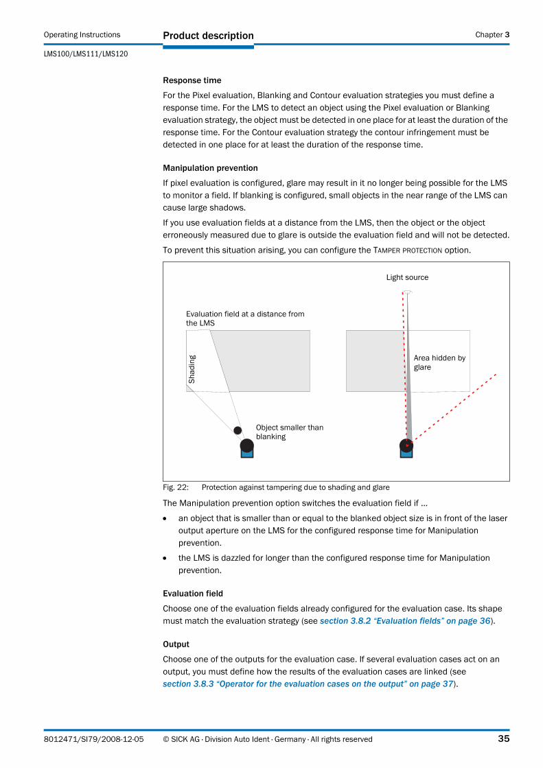
Manipulation prevention
If pixel evaluation is configured, glare may result in it no longer being possible for the LMS to monitor a field. If blanking is configured, small objects in the near range of the LMS can cause large shadows.
If you use evaluation fields at a distance from the LMS, then the object or the object erroneously measured due to glare is outside the evaluation field and will not be detected.
To prevent this situation arising, you can configure the TAMPER PROTECTION option.
Fig. 22: Protection against tampering due to shading and glare
The Manipulation prevention option switches the evaluation field if …
• an object that is smaller than or equal to the blanked object size is in front of the laser output aperture on the LMS for the configured response time for Manipulation prevention.
• the LMS is dazzled for longer than the configured response time for Manipulation prevention.
Evaluation field
Choose one of the evaluation fields already configured for the evaluation case. Its shape must match the evaluation strategy (see section 3.8.2 “Evaluation fields” on page 36).
Output
Choose one of the outputs for the evaluation case. If several evaluation cases act on an output, you must define how the results of the evaluation cases are linked (see section 3.8.3 “Operator for the evaluation cases on the output” on page 37).
Object smaller than blanking
Area hidden by glare
Shad
ing
Light source
Evaluation field at a distance from the LMS
8012471/SI79/2008-12-05 © SICK AG · Division Auto Ident · Germany · All rights reserved 35

Product description Operating Instructions
LMS100/LMS111/LMS120 Laser Measurement Systems
Chapter 3
Negating the result
By negating the result the field evaluation is signalled in reverse on the output. The output used is, e.g., then switched if the evaluation field is clear or if the contour is not infringed.
Important Do not confuse the negation of the result with the setting active high/active low for the outputs (see section 3.8.3 “Operator for the evaluation cases on the output” on page 37).
3.8.2 Evaluation fields
With the aid of the integrated field application, you can configure up to ten evaluation fields. The size and shape of these ten evaluation fields can be configured almost entirely as required.
Fig. 23: Examples of different evaluation field shapes
The evaluation fields can be drawn using SOPAS ET to suit the needs of your application. Evaluation fields can have the following shapes:
• polygon
• rectangular
• reaching the LMS
• at a distance from the LMS
• dynamic (the length changes with speed measured using the encoder, see 3.9.2 on page 37)
You can configure the evaluation fields in SOPAS ET:
PROJECT TREE, LMS100_FIELDEVAL, PARAMETER, EVALUATION FIELDS.
If the area to be monitored changes, then you can re-configure the LMS via software without additional mounting effort.
Three digital outputs
LMS
Evaluation field for contour monitoring
Dynamic evaluation field
Rectangularevaluation field at
a distance fromthe LMS
Polygon evaluation field
Rotated evaluation field
Measurement area of the LMS
36 © SICK AG · Division Auto Ident · Germany · All rights reserved 8012471/SI79/2008-12-05
Operating Instructions
LMS100/LMS111/LMS120
Product description Chapter 3
3.8.3 Operator for the evaluation cases on the output
If several evaluation cases act on an output, you must define how the results of the evaluation cases are linked. The related results can be linked using an AND or an OR operator.
PROJECT TREE, LMS100_FIELDEVAL, PARAMETER, NETWORK/INTERFACES/IOS, DIGITAL OUTPUTS.
The outputs are configured as active high in the pre-setting. You can configure the outputs also as active low.
Resetting an output
By default the outputs are reset immediately. You can configure a delay of up to 10 s (e.g. to activate a horn or to send the output signal to a PLC).
An an alternative you can also reset the output using an input. The output is then only reset when the allocated input has the configured status.
3.9 Inputs and outputs
3.9.1 Digital switching inputs
The LMS has 2 digital switching inputs. These inputs can switch on and off evaluation cases (see section 3.8.1 “Evaluation cases” on page 34). With the aid of the inputs, the outputs on the LMS can also be reset (see section “Resetting an output” on page 37).
3.9.2 Encoder inputs
The LMS has 2 digital inputs for an encoder.
With the aid of the encoder pulses, the size of so-called dynamic fields can be changed, e.g., for speed-dependent vehicle monitoring. The length of a dynamic field changes with the speed measured, e.g. using an encoder.
PROJECT TREE, LMS100_FIELDEVAL, PARAMETER, INCREMENT CONFIGURATION.
When stationary (V = 0 m/s) the evaluation field is the same size as the basic field configured. The size increases continuously with increasing speed up to the largest physical size for the field at the maximum speed.
3.9.3 Digital switching outputs
The LMS has three digital switching outputs.
The outputs can be used as digital switching outputs to ground, as floating outputs or as resistance monitored outputs. The latter provides a VdS-compliant connection layout (see section 5.4.5 “Wiring of inputs and outputs on the LMS” on page 61).
For each output you configure whether it is switched by the field evaluation application or via SOPAS ET messages, or whether it is used to signal the device is ready.
PROJECT TREE, LMS100_FIELDEVAL, PARAMETER, NETWORK/INTERFACES/IOS, DIGITAL OUTPUTS.
If an output is switched by the field evaluation application, the LMS can signal evaluation field infringements or contour infringements. For this purpose, configure in SOPAS ET which evaluation case is to act on which output.
3.9.4 External switching outputs
A CAN module can be supplied to expand the switching outputs. With this module additional external switching outputs are made available.
8012471/SI79/2008-12-05 © SICK AG · Division Auto Ident · Germany · All rights reserved 37

Product description Operating Instructions
LMS100/LMS111/LMS120 Laser Measurement Systems
Chapter 3
The external switching outputs have the same functionality as the digital switching outputs on the LMS.
PROJECT TREE, LMS100_FIELDEVAL, PARAMETER, NETWORK/INTERFACES/IOS, EXTERNAL OUTPUTS.
3.9.5 Logical operators for inputs and outputs
With the aid of an evaluation case the inputs and outputs on several LMS can be linked together (see section 3.8.1 “Evaluation cases” on page 34).
Fig. 24: Logical operators for inputs and outputs
In the example output 1 on the LMS at the bottom is connected to input 1 on the LMS at the top. An evaluation field infringement is therefore signalled at the input on the LMS at the top. This LMS links the input to output 1 in its evaluation case 2. At the same time, evaluation case 1 also acts on the LMS at the top and its output 1. Using the OR operator for the two results, evaluation field infringements on both LMS are signalled on output 1 on the LMS at the top.
3.9.6 Sabotage outputs
Several sabotage contacts in the LMS120 protect the laser measurement system against tampering. If it is attempted to open the housing or to remove the system plug, the contacts are opened. An object protection system connected to the device can then trigger an ALARM if sabotage is attempted.
3.10 Data interfaces
The LMS has different data interfaces for the configuration and the transmission of measured values.
Important • It is only possible to output all measured values of a scan in real-time using the Ethernet interface.
Evaluation case 1:pixel evaluation acts on output 1
Evaluation case 1:pixel evaluation
acts on output 1
Evaluation case 2:I/O operator
acts on output 1
Output 1:OR operator for the evaluation cases 1 and 2
Input 1:active low
Output 1:active low
Protective fields on two LMS linked using I/O operator
38 © SICK AG · Division Auto Ident · Germany · All rights reserved 8012471/SI79/2008-12-05

Operating Instructions
LMS100/LMS111/LMS120
Product description Chapter 3
• The data transmission rate of the RS232 interfaces is limited. Therefore these interfaces are not suitable for transmitting scan data in real time.
3.10.1 Ethernet interface
The Ethernet interface has a data transmission rate of 10/100 MBit. The interface is a TCP/IP interface. Full duplex and half duplex are supported.
The Ethernet interface allows the configuration of the LMS as well as the output of measured values.
The factory setting for the Ethernet interface is as follows:
• IP address: 192.168.0.1
• subnet mask: 255.255.255.0
• TCP port: 2111
If necessary, adjust the TCP/IP configuration for the Ethernet interface to enable a connected PC (client) to communicate with the LMS via Ethernet: PROJECT TREE,LMS100_FIELDEVAL, NETWORK/INTERFACES/IOS, ETHERNET.
Important If you change the parameters for the Ethernet interface over the Ethernet interface, you must first save the data in non-volatile memory in the LMS and then restart the LMS. For this purpose there is the RESTART button in SOPAS_ET.
You will find a description of the electrical interface in section 5.2 “Connections of the LMS” on page 53.
3.10.2 CAN
Important The LMS supports the CAN standard 2.0A.
The CAN interface supports data transmissions between 10 Bit/s and 1 Mbit/s.
For data communication via CAN you must configure the LMS so that it can communicate with the host:
PROJECT TREE, LMS100_FIELDEVAL, NETWORK/INTERFACES/IOS, CAN.
The following interface parameters can be configured
• baud rate of the CAN bus
• ID of the LMS in CAN
3.10.3 Serial host interface
The serial host interface is an RS-232 interface. The host interface permits the configuration of the LMS and only limited measured value output.
The interface parameters are freely configurable:
PROJECT TREE, LMS100_FIELDEVAL, NETWORK/INTERFACES/IOS, SERIAL, area SERIAL HOST INTERFACE.
8012471/SI79/2008-12-05 © SICK AG · Division Auto Ident · Germany · All rights reserved 39

Product description Operating Instructions
LMS100/LMS111/LMS120 Laser Measurement Systems
Chapter 3
The factory setting for the host interface is as follows:
• 57,600 Baud
• 8 data bits
• 1 stop bit
• no parity
Important If you change the parameters for the host interface over the host interface, the connection to the device will be lost. You must then scan for the LMS again in SOPAS ET (see section 6.3.5 “Performing scan” on page 68).
You will find a description of the electrical interface in section 5.2 “Connections of the LMS” on page 53.
3.10.4 Serial auxiliary interface
The serial auxiliary interface is an RS-232 interface. The auxiliary interface permits the configuration of the LMS.
The interface parameters are freely configurable:
PROJECT TREE, LMS100_FIELDEVAL, NETWORK/INTERFACES/IOS, SERIAL, area SERIAL AUXILIARY INTERFACE.
The factory setting for the auxiliary interface is as follows:
• 57,600 Baud
• 8 data bits
• 1 stop bit
• no parity
Important If you change the parameters for the auxiliary interface over the auxiliary interface, the connection to the device will be lost. You must then scan for the LMS again in SOPAS ET (see section 6.3.5 “Performing scan” on page 68).
You will find a description of the electrical interface in section 5.2 “Connections of the LMS” on page 53.
3.11 Data communication using messages
The LMS sends messages over the interfaces described above to communicate with a connected host. The following functions can be run using messages:
• request for measured values by the host and subsequent output of the measured values by the LMS
• parameter setting by the host for the configuration of the LMS
• parameters and status log querying by the host
The messages each comprise a frame (see 3.11.1 on page 41) and the data.
A detailed description of the different messages can be found in the annex (see section 10.2 “Messages” on page 84).
40 © SICK AG · Division Auto Ident · Germany · All rights reserved 8012471/SI79/2008-12-05

Operating Instructions
LMS100/LMS111/LMS120
Product description Chapter 3
3.11.1 Frame and coding for the messages
The data frame varies depending on the coding.
Messages with ASCII coding
The frame for the serial host interface can be configured in SOPAS ET: PROJECT TREE,LMS100-XX00, INTERFACES, SERIAL, area SERIAL HOST INTERFACE.
In this way, for example, you can use two stop bytes (e.g. to end messages with CR/LF).
Messages with binary coding
Calculation of the checksum
The checksum is calculated using an XOR operator for every byte of the data, that is without the frame.
3.12 Planning
3.12.1 LMS system requirements
For commissioning and operating the LMS, the following are required:
• LMS100 and LMS111: supply voltage DC 10.8 … 30 V, generated as per IEC 364441 (VDE 0100, part 410), output power minimum 20 W
• LMS120: supply voltage 9 … 30 V DC, generated as per IEC 364441 (VDE 0100, part 410), output power minimum 20 W
• LMS111: supply voltage for the heating 24 V DC, Output power minimum 40 W (cyclic)
• data interface RS232, Ethernet and CAN (optional, in case several LMS are connected together in a network) (see also section 5.3.3 “General conditions for the data interface” on page 58)
• PC with operating system Windows 2000™, Windows XP™ or Windows Vista™ (see also section 6.2.1 “System requirements for SOPAS ET” on page 66)
Frame Message Frame
Code STX Data (see section 10.2 “Messages” on page 84) ETX
Length (byte) 1 ≤ 30 kB 1
Description Start of text character ASCII coded. The length is dependent on the previous send message.
End of text character
Tab. 8: Frame for the messages with ASCII coding
Frame Message Frame
Code STX STX STX STX Message length Data (see 10.2 on page 84) Checksum
Length (byte) 1 1 1 1 4 ≤ 2,495 1
Description Start of text character Length of the data without CS
Binary encoded. The length is dependent on the previous send message.
See “Calculation of the checksum” further below
Tab. 9: Frame for the messages with binary coding
8012471/SI79/2008-12-05 © SICK AG · Division Auto Ident · Germany · All rights reserved 41
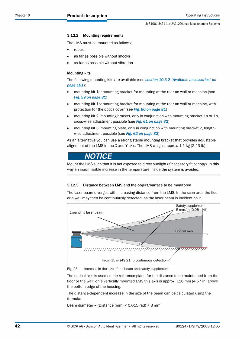
Product description Operating Instructions
LMS100/LMS111/LMS120 Laser Measurement Systems
Chapter 3
3.12.2 Mounting requirements
The LMS must be mounted as follows:
• robust
• as far as possible without shocks
• as far as possible without vibration
Mounting kits
The following mounting kits are available (see section 10.3.2 “Available accessories” on page 101):
• mounting kit 1a: mounting bracket for mounting at the rear on wall or machine (see Fig. 59 on page 81)
• mounting kit 1b: mounting bracket for mounting at the rear on wall or machine, with protection for the optics cover (see Fig. 60 on page 81)
• mounting kit 2: mounting bracket, only in conjunction with mounting bracket 1a or 1b, cross-wise adjustment possible (see Fig. 61 on page 82)
• mounting kit 3: mounting plate, only in conjunction with mounting bracket 2, length-wise adjustment possible (see Fig. 62 on page 82)
As an alternative you can use a strong stable mounting bracket that provides adjustable alignment of the LMS in the X and Y axis. The LMS weighs approx. 1.1 kg (2.43 lb).
Mount the LMS such that it is not exposed to direct sunlight (if necessary fit canopy). In this way an inadmissible increase in the temperature inside the system is avoided.
3.12.3 Distance between LMS and the object/surface to be monitored
The laser beam diverges with increasing distance from the LMS. In the scan area the floor or a wall may then be continuously detected, as the laser beam is incident on it.
Fig. 25: Increase in the size of the beam and safety supplement
The optical axis is used as the reference plane for the distance to be maintained from the floor or the wall; on a vertically mounted LMS this axis is approx. 116 mm (4.57 in) above the bottom edge of the housing.
The distance-dependent increase in the size of the beam can be calculated using the formula:
Beam diameter = (Distance (mm) × 0.015 rad) + 8 mm
Safety supplement5 mm/m (0.06 in/ft)
From 15 m (49.21 ft) continuous detection
Optical axis
Expanding laser beam
42 © SICK AG · Division Auto Ident · Germany · All rights reserved 8012471/SI79/2008-12-05

Operating Instructions
LMS100/LMS111/LMS120
Product description Chapter 3
The following table shows a few values as examples:
For the assessment of whether the laser beam can be incident on an object or the wall, the distance of half the beam diameter from the optical axis is used.
Recommendation Take into account a safety supplement of approx. 5 mm per meter (0.06 in/ft).
Distance 5 m(16.40 ft)
10 m (32.81 ft)
15 m (49.21 ft)
20 m (65.62 ft)
Beam diameter 83 mm (3.27 in)
158 mm (6.23 in)
233 mm (9.18 in)
308 mm (12.14 in)
Tab. 10: Beam diameter at different distances from the LMS
8012471/SI79/2008-12-05 © SICK AG · Division Auto Ident · Germany · All rights reserved 43
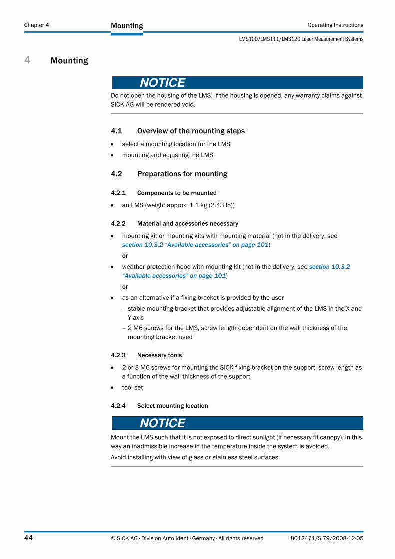
Mounting Operating Instructions
LMS100/LMS111/LMS120 Laser Measurement Systems
Chapter 4
4 Mounting
Do not open the housing of the LMS. If the housing is opened, any warranty claims against SICK AG will be rendered void.
4.1 Overview of the mounting steps
• select a mounting location for the LMS
• mounting and adjusting the LMS
4.2 Preparations for mounting
4.2.1 Components to be mounted
• an LMS (weight approx. 1.1 kg (2.43 lb))
4.2.2 Material and accessories necessary
• mounting kit or mounting kits with mounting material (not in the delivery, see section 10.3.2 “Available accessories” on page 101)
or
• weather protection hood with mounting kit (not in the delivery, see section 10.3.2 “Available accessories” on page 101)
or
• as an alternative if a fixing bracket is provided by the user
– stable mounting bracket that provides adjustable alignment of the LMS in the X and Y axis
– 2 M6 screws for the LMS, screw length dependent on the wall thickness of the mounting bracket used
4.2.3 Necessary tools
• 2 or 3 M6 screws for mounting the SICK fixing bracket on the support, screw length as a function of the wall thickness of the support
• tool set
4.2.4 Select mounting location
Mount the LMS such that it is not exposed to direct sunlight (if necessary fit canopy). In this way an inadmissible increase in the temperature inside the system is avoided.
Avoid installing with view of glass or stainless steel surfaces.
44 © SICK AG · Division Auto Ident · Germany · All rights reserved 8012471/SI79/2008-12-05

Operating Instructions
LMS100/LMS111/LMS120
Mounting Chapter 4
4.3 Mounting steps
Special features to note during mounting:
Mount the LMS such that it is protected from moisture, dirt and damage.
Ensure that the entire field of view of the LMS is not restricted.
Mount the laser measurement system such that the indicators are easy to see.
Always mount the LMS so that there is still enough space for mounting and removing the system plug.
Avoid excessive shock and vibration loading on the laser measurement system.
On applications that suffer from heavy vibration, prevent the fixing screws from coming loose using screw locking devices (see section 9.1 “Data sheet LMS laser measurement system” on page 74).
Regularly check the tightness of the fixing screws.
Pay attention to the maximum torque of the M5 fixing screws on the LMS of max. 5.9 Nm.
The LMS can be fastened in the following ways:
• direct mounting without mounting kit
• mounting with mounting kit 1a or 1b
• mounting with mounting kit 2 (only in conjunction with mounting kit 1a or 1b)
• mounting with weather protection hood 190° and the related mounting kit
• mounting with weather protection hood 190° and the quick-action mounting kit
• mounting with weather protection hood 270° and the related mounting kit
• mounting with weather protection hood 270° and the quick-action mounting kit
You will find the part numbers for the mounting kits in section 10.3.2 “Available accessories” on page 101.
8012471/SI79/2008-12-05 © SICK AG · Division Auto Ident · Germany · All rights reserved 45
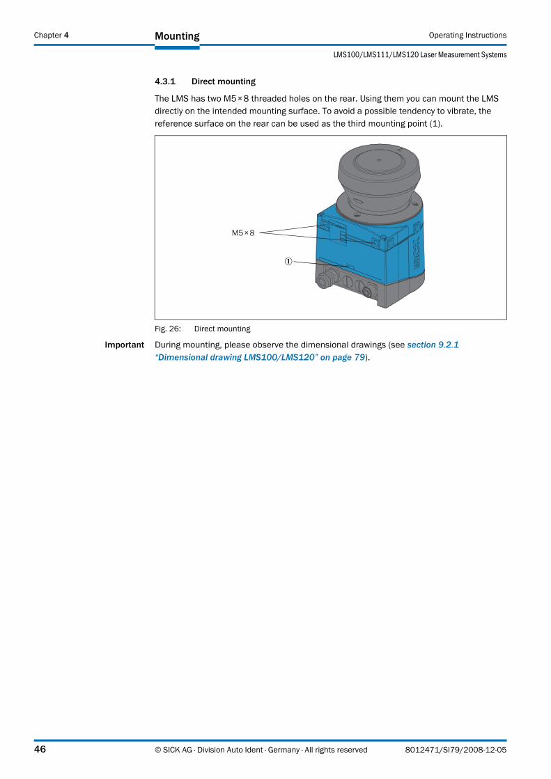
Mounting Operating Instructions
LMS100/LMS111/LMS120 Laser Measurement Systems
Chapter 4
4.3.1 Direct mounting
The LMS has two M5×8 threaded holes on the rear. Using them you can mount the LMS directly on the intended mounting surface. To avoid a possible tendency to vibrate, the reference surface on the rear can be used as the third mounting point (1).
Fig. 26: Direct mounting
Important During mounting, please observe the dimensional drawings (see section 9.2.1 “Dimensional drawing LMS100/LMS120” on page 79).
M5×8
46 © SICK AG · Division Auto Ident · Germany · All rights reserved 8012471/SI79/2008-12-05

Operating Instructions
LMS100/LMS111/LMS120
Mounting Chapter 4
4.3.2 Mounting with mounting kit 1a or 1b
With the aid of mounting kit 1 you can mount the LMS on a mounting surface (wall, machine). The mounting kit is available as mounting kit 1a without protection device for the optics cover and as mounting kit 1b with protection device for the optics cover.
Fig. 27: Mounting with mounting kit 1a
Fig. 28: Mounting with mounting kit 1b
1. Mount mounting kit 1a or 1b on the mounting surface.
2. Then mount the LMS on the mounting kit 1a or 1b.
Important During mounting, please observe the dimensional drawings (see section 9.2.3 “Dimensional drawings, mounting kits” on page 81).
Threaded holes M5×8
Fixing screws
Fixing screws
Mounting kit 1a
Threaded holes M5×8
Fixing screws
Fixing screws
Mounting kit 1b
8012471/SI79/2008-12-05 © SICK AG · Division Auto Ident · Germany · All rights reserved 47

Mounting Operating Instructions
LMS100/LMS111/LMS120 Laser Measurement Systems
Chapter 4
4.3.3 Mounting with mounting kit 2 and 3
With the aid of mounting kits 2 and 3 (only in conjunction with mounting kit 1a or 1b) you can align the LMS in two planes. The maximum adjustment angle is ±11° in both planes.
Fig. 29: Mounting with mounting kit 2 and 3
1. Mount mounting kit 1a or 1b to the LMS.
2. Mount the mounting kit 3 on the mounting surface.
3. Fit the centring pin (4 mm (0.16 in)) in the central hole on mounting bracket 3.
4. Fit mounting kit 2 to mounting kit 3 and mount it using two fixing screws M4×10.
5. Then mount the LMS on mounting kit 2 with the aid of the threaded holes in mounting kit 1a.
6. Adjust the LMS longitudinally and transversely and then tighten the six fixing screws on the mounting kits.
Important During mounting, please observe the dimensional drawings (see section 9.2.3 “Dimensional drawings, mounting kits” on page 81).
Centring pin
Mounting kit 1a Mounting kit 2 Mounting kit 3
Threaded holes M4
48 © SICK AG · Division Auto Ident · Germany · All rights reserved 8012471/SI79/2008-12-05

Operating Instructions
LMS100/LMS111/LMS120
Mounting Chapter 4
4.3.4 Mounting the LMS111 with weather protection hood
To protect the LMS111 from glare and precipitation when used outside, two weather protection hoods are available.
• The weather protection hood 190° provides a field of view of 190° and practically flat mounting on the application.
• The weather protection hood 270° provides a larger field of view of 270°, but not flat mounting on the application.
You will find detailed dimensions in section 9.2.4 “Dimensional drawings, weather protection hoods” on page 83.
Fig. 30: Weather protection hood 190°
Fig. 31: Weather protection hood 270°
How to mount the weather protection hood on the LMS111:
1. Put the weather protection hood 190° or 270° over the LMS111.
2. Mount the weather protection hood on the LMS111 using three M5×15 countersunk head screws (included with the delivery of the weather protection hood).
For this purpose you will find on the weather protection hood two holes with 90° countersink on the rear and one hole with 90° countersink on the right.
Weather protection hood
LMS111
Weather protection hood
LMS111
8012471/SI79/2008-12-05 © SICK AG · Division Auto Ident · Germany · All rights reserved 49
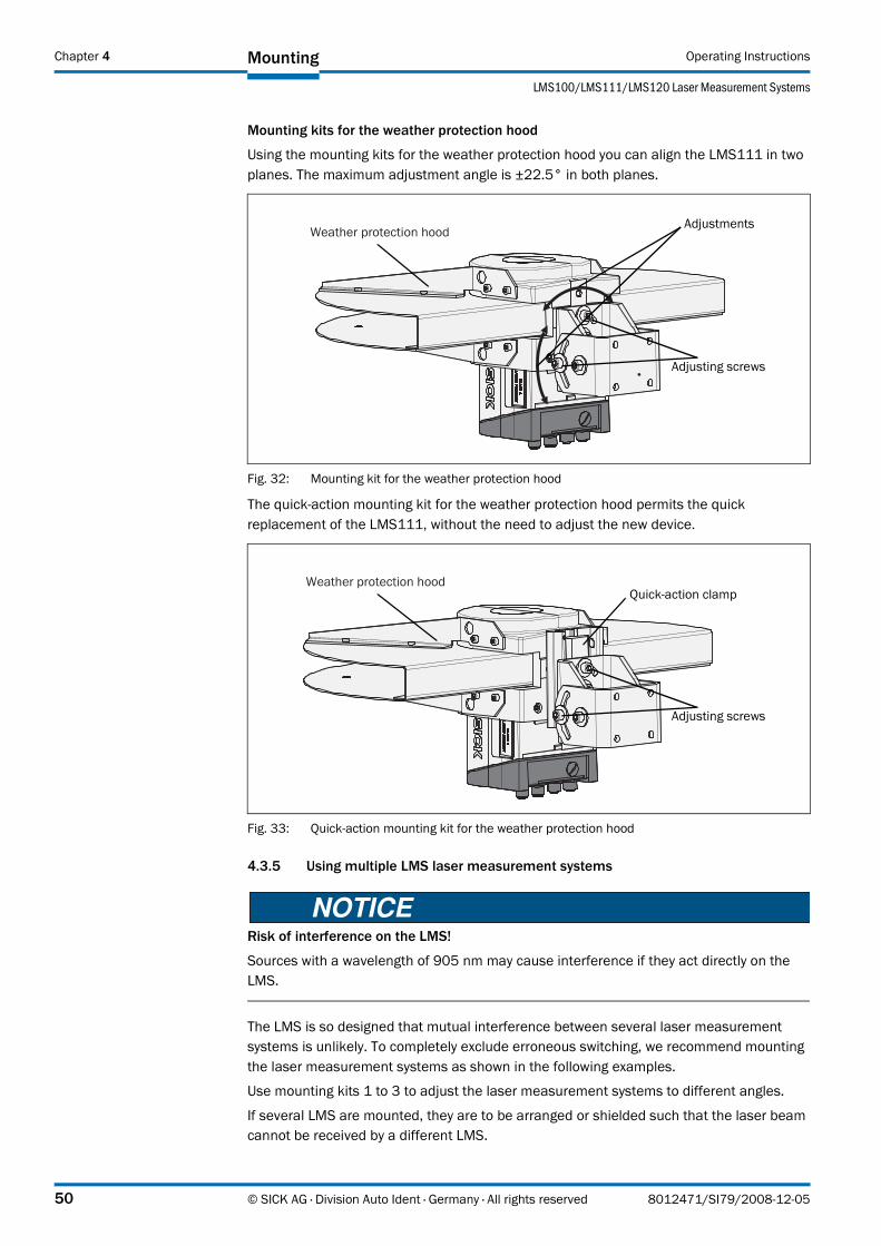
Mounting Operating Instructions
LMS100/LMS111/LMS120 Laser Measurement Systems
Chapter 4
Mounting kits for the weather protection hood
Using the mounting kits for the weather protection hood you can align the LMS111 in two planes. The maximum adjustment angle is ±22.5° in both planes.
Fig. 32: Mounting kit for the weather protection hood
The quick-action mounting kit for the weather protection hood permits the quick replacement of the LMS111, without the need to adjust the new device.
Fig. 33: Quick-action mounting kit for the weather protection hood
4.3.5 Using multiple LMS laser measurement systems
Risk of interference on the LMS!
Sources with a wavelength of 905 nm may cause interference if they act directly on the LMS.
The LMS is so designed that mutual interference between several laser measurement systems is unlikely. To completely exclude erroneous switching, we recommend mounting the laser measurement systems as shown in the following examples.
Use mounting kits 1 to 3 to adjust the laser measurement systems to different angles.
If several LMS are mounted, they are to be arranged or shielded such that the laser beam cannot be received by a different LMS.
Weather protection hood
Adjusting screws
Adjustments
Weather protection hood
Adjusting screws
Quick-action clamp
50 © SICK AG · Division Auto Ident · Germany · All rights reserved 8012471/SI79/2008-12-05

Operating Instructions
LMS100/LMS111/LMS120
Mounting Chapter 4
Correct placement of several LMS
Arrange or shield several LMS such that the laser beam cannot be received by a different LMS.
Fig. 34: Placement of two LMS opposed to each other
Fig. 35: Crosswise placement of two LMS
Fig. 36: Placement of two LMS with parallel offset
Fig. 37: Placement of two LMS with parallel offset, one of these upside down
8012471/SI79/2008-12-05 © SICK AG · Division Auto Ident · Germany · All rights reserved 51

Mounting Operating Instructions
LMS100/LMS111/LMS120 Laser Measurement Systems
Chapter 4
Fig. 38: Placement of two LMS upside down, parallel offset
Fig. 39: Placement of two LMS with parallel offset, one of these upside down
4.4 Dismanteling the system
1. Switch off the supply voltage.
2. Remove the connection cables.
3. Undo the mounting screws for the LMS to the mounting bracket and remove the device.
Important On final decommissioning, please observe the disposal requirements in section 2.5.2 “Disposal after final de-commissioning” on page 15 for environmentally correct disposal.
52 © SICK AG · Division Auto Ident · Germany · All rights reserved 8012471/SI79/2008-12-05

Operating Instructions
LMS100/LMS111/LMS120
Electrical installation Chapter 5
5 Electrical installation
Only authorised personnel are allowed to perform the electrical installation work.
Do not open the housing.
Observe the current safety regulations when working on electrical systems.
Switch the entire machine/system offline!
The machine/system could inadvertently start up while you are connecting the device.
Ensure that the entire machine/system is disconnected during the electrical installation.
The LMS complies with the requirements in the standard on the radiated emissions as defined for class A (industrial environment). It may cause radio interference in residential areas. If radio interference occurs, the person(s) affected may demand that the operator take appropriate action for suppressing interference.
5.1 Overview of the installation steps
• Connect the supply voltage to the LMS.
• Wire switching outputs (application-dependent).
• Temporarily connect PC (configuration).
• Wire data interface for operation.
5.2 Connections of the LMS
Depending on the variant, the LMS has different connections:
• The LMS100 and the LMS120 have a removable system plug. This has a PG7 cable entry on the rear. The connections are made to the 34pin screw type terminal in the system plug. In addition the variant has a round M12 plug connector for the connection to Ethernet.You can move the G7 cable entry and the round plug connector from the rear to the underside of the system plug (see section 9.2.1 “Dimensional drawing LMS100/LMS120” on page 79).
• The LMS111 has four multipin round M12 plug connectors. The connections are made to the related plug or sockets.
• All variants have a round M8 plug connector on the front of the unit for the connection to the RS232 interface on a PC.
Important This interface is only used for configuration and is not allowed to be permanently connected.
8012471/SI79/2008-12-05 © SICK AG · Division Auto Ident · Germany · All rights reserved 53

Electrical installation Operating Instructions
LMS100/LMS111/LMS120 Laser Measurement Systems
Chapter 5
5.2.1 Connections of the LMS100
“Ethernet” connection M12×4, socket
Terminal Signal Function1 Reserved Do not use2 Reserved Do not use3 RxD RS232 Serial RS232 host interface (receiver)4 Reserved Do not use5 Reserved Do not use6 IN1 Digital input 1 7 IN1 GND Ground digital input 18 IN2 Digital input 2 9 IN2 GND Ground digital input 210 A1_INCA_0 Encoder input 111 A1_INCA_90 Encoder input 212 GNDINC_A Ground digital inputs13 OUT1_A Digital output 114 OUT1_B (or _GND) Digital output 115 OUT1_R Resistance monitor output 1 16 OUT2_A Digital output 217 OUT2_B (or _GND) Digital output 218 GND Ground LMS19 VS 10.8 V … 30 V LMS supply voltage20 TxD RS232 Serial RS232 host interface (sender)21 Reserved Do not use22 GND RS232/GND CAN Ground serial host interface or CAN23 CAN_H CAN-BUS High24 CAN_L CAN-BUS Low25 CAN Vs 24 V CAN supply voltage26 GND RS232/GND CAN Ground serial host interface or CAN27 CAN_H CAN-BUS Low28 CAN_L CAN-BUS High29 CAN Vs 24 V CAN supply voltage30 OUT3_R Resistance monitor digital output 3 31 OUT3_B (or _GND) Digital output 332 OUT3_A Digital output 333 OUT2_R Resistance monitor digital output 234 Case Housing
Tab. 11: Terminal assignment of the LMS100
Pin Signal Function1 Ethernet_TX+ Ethernet interface2 Ethernet_RX+ Ethernet interface3 Ethernet_TX– Ethernet interface4 Ethernet_RX– Ethernet interface
Tab. 12: Pin assignment of the “Ethernet” connection on the LMS100
32
41
54 © SICK AG · Division Auto Ident · Germany · All rights reserved 8012471/SI79/2008-12-05

Operating Instructions
LMS100/LMS111/LMS120
Electrical installation Chapter 5
“Auxiliary interface” connection M8×4, socket
5.2.2 Connections of the LMS120
Pin Signal Function1 – Not assigned2 RxD Serial RS232 auxiliary interface3 0 VDC Ground4 TxD Serial RS232 auxiliary interface
Tab. 13: Pin assignment of the “Auxiliary interface” connection on the LMS100
24
13
Terminal Signal Function1 Reserved Do not use2 Reserved Do not use3 RxD Serial RS232 host interface (receiver)4 Sabotage1 Sabotage output5 Sabotage0 Sabotage output6 IN1 Digital input 1 7 IN1 GND Ground digital input 18 IN2 Digital input 2 9 IN2 GND Ground digital input 210 A1_INCA_0 Encoder input 111 A1_INCA_90 Encoder input 212 GNDINC_A Ground digital inputs13 OUT1_A Digital output 114 OUT1_B (or _GND) Digital output 115 OUT1_R Resistance monitor output 1 16 OUT2_A Digital output 217 OUT2_B (or _GND) Digital output 218 GND Ground19 VS LMS supply voltage20 TxD Serial RS232 host interface (sender)21 SabotageR Resistance monitor sabotage output22 GND RS232/GND CAN Ground RS232 interface or CAN23 CAN_H CAN-BUS High24 CAN_L CAN-BUS Low25 CAN 24 V CAN supply voltage26 GND RS232/GND CAN Ground RS232 interface or CAN27 CAN_H CAN-BUS Low28 CAN_L CAN-BUS High29 CAN 24 V CAN supply voltage30 OUT3_R Resistance monitor digital output 3 31 OUT3_B (or _GND) Digital output 332 OUT3_A Digital output 333 OUT2_R Resistance monitor digital output 234 Case Housing
Tab. 14: Terminal assignment of the LMS120
8012471/SI79/2008-12-05 © SICK AG · Division Auto Ident · Germany · All rights reserved 55
Electrical installation Operating Instructions
LMS100/LMS111/LMS120 Laser Measurement Systems
Chapter 5
“Ethernet” connection M12×4, socket
“Auxiliary interface” connection M8×4, socket
5.2.3 Connections of the LMS111
“Power” connection M12×5, plug
“RS232” connection M12×8, plug
Pin Signal Function1 Ethernet_TX+ Ethernet interface2 Ethernet_RX+ Ethernet interface3 Ethernet_TX– Ethernet interface4 Ethernet_RX– Ethernet interface
Tab. 15: Pin assignment of the “Ethernet” connection on the LMS120
32
41
Pin Signal Function1 – Not assigned2 RxD Serial RS232 auxiliary interface3 0 VDC Ground4 TxD Serial RS232 auxiliary interface
Tab. 16: Pin assignment of the “Auxiliary interface” connection on the LMS120
24
13
Pin Signal Function1 VS LMS supply voltage2 Vs heat. Supply voltage for the heating3 GND Ground4 – Not assigned5 GND heat. Ground heating
Tab. 17: Pin assignment of the “Power” connection on the LMS111
2
1
4
3
5
Pin Signal Function1 RxD Serial RS232 host interface (receiver)2 TxD Serial RS232 host interface (sender)3 CAN_H CAN-BUS High4 CAN_L CAN-BUS Low5 GND CAN Ground CAN6 IN1 Digital input 1 7 IN2 Digital input 2 8 IN GND Ground digital inputs
Tab. 18: Pin assignment of the “RS232” connection on the LMS111
2
1
7
65
4
3
8
56 © SICK AG · Division Auto Ident · Germany · All rights reserved 8012471/SI79/2008-12-05
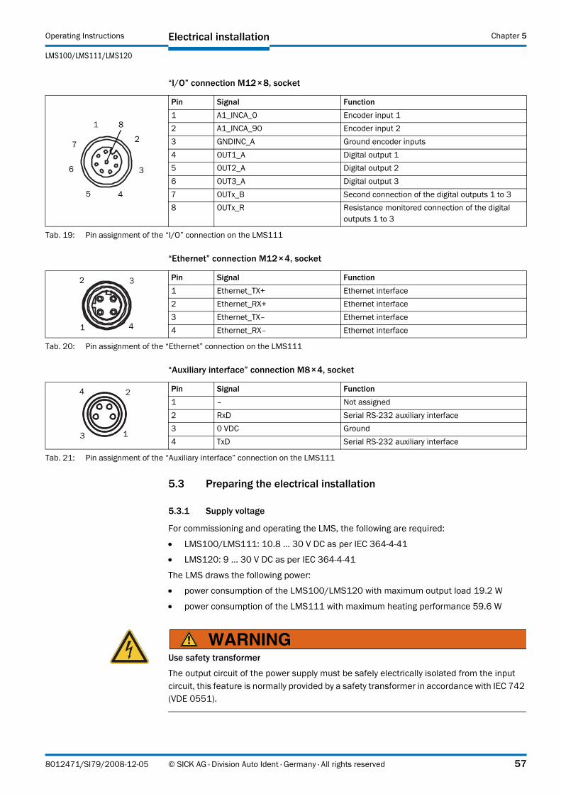
Operating Instructions
LMS100/LMS111/LMS120
Electrical installation Chapter 5
“I/O” connection M12×8, socket
“Ethernet” connection M12×4, socket
“Auxiliary interface” connection M8×4, socket
5.3 Preparing the electrical installation
5.3.1 Supply voltage
For commissioning and operating the LMS, the following are required:
• LMS100/LMS111: 10.8 … 30 V DC as per IEC 364441
• LMS120: 9 … 30 V DC as per IEC 364441
The LMS draws the following power:
• power consumption of the LMS100/LMS120 with maximum output load 19.2 W
• power consumption of the LMS111 with maximum heating performance 59.6 W
Use safety transformer
The output circuit of the power supply must be safely electrically isolated from the input circuit, this feature is normally provided by a safety transformer in accordance with IEC 742 (VDE 0551).
Pin Signal Function1 A1_INCA_0 Encoder input 12 A1_INCA_90 Encoder input 23 GNDINC_A Ground encoder inputs4 OUT1_A Digital output 1 5 OUT2_A Digital output 2 6 OUT3_A Digital output 37 OUTx_B Second connection of the digital outputs 1 to 38 OUTx_R Resistance monitored connection of the digital
outputs 1 to 3
Tab. 19: Pin assignment of the “I/O” connection on the LMS111
1
2
3
45
6
7
8
Pin Signal Function1 Ethernet_TX+ Ethernet interface2 Ethernet_RX+ Ethernet interface3 Ethernet_TX– Ethernet interface4 Ethernet_RX– Ethernet interface
Tab. 20: Pin assignment of the “Ethernet” connection on the LMS111
32
41
Pin Signal Function1 – Not assigned2 RxD Serial RS232 auxiliary interface3 0 VDC Ground4 TxD Serial RS232 auxiliary interface
Tab. 21: Pin assignment of the “Auxiliary interface” connection on the LMS111
24
13
8012471/SI79/2008-12-05 © SICK AG · Division Auto Ident · Germany · All rights reserved 57

Electrical installation Operating Instructions
LMS100/LMS111/LMS120 Laser Measurement Systems
Chapter 5
5.3.2 Wire cross-sections
Wire all connections with copper cables!
Use the following wire cross-sections:
• supply voltage at least 0.25 mm2 (approx. 24 AWG), if local power supply in the immediate vicinity
• supply voltage at least 1.0 mm2 (approx. 18 AWG) at maximum length of 20 m (65.62 ft), if the connection is made to an existing 24 V DC supply
• switching outputs minimum 0.25 mm2 (approx. 24 AWG), maximum cable length 50 m (164.04 ft) with 0.5 mm2 (approx. 22 AWG)
• data interface minimum 0.25mm2 (approx. 24 AWG)
• For the LMS the outside diameter of the common cable must be a maximum of 9 mm (0.35 in) due to the cable entry.
5.3.3 General conditions for the data interface
The table below shows the recommended maximum length of cable as a function of the data transmission rate selected.
Important • Use screened cable (twisted-pair) with at least 0.25 mm2 (approx. 24 AWG).
• To prevent interference, do not lay data cable in parallel with power supply and motor cables over a long run, e.g. in cable ducts.
5.4 Perform electrical installation on the LMS
Lay all cables such that there is no risk of tripping and all cables are protected against damage.
5.4.1 Equipment
• tool set
• digital multimeter (current/voltage measurement)
Interface type Transmission rate Maximum cable lengthRS232 115,200 Bd 10 m (32.81 ft)CAN bus1)
1) With appropriate cable termination, termination in accordance with related specification.
1 MBit/s 40 m (131.23 ft)
Tab. 22: Maximum cable lengths for the data interfaces
58 © SICK AG · Division Auto Ident · Germany · All rights reserved 8012471/SI79/2008-12-05
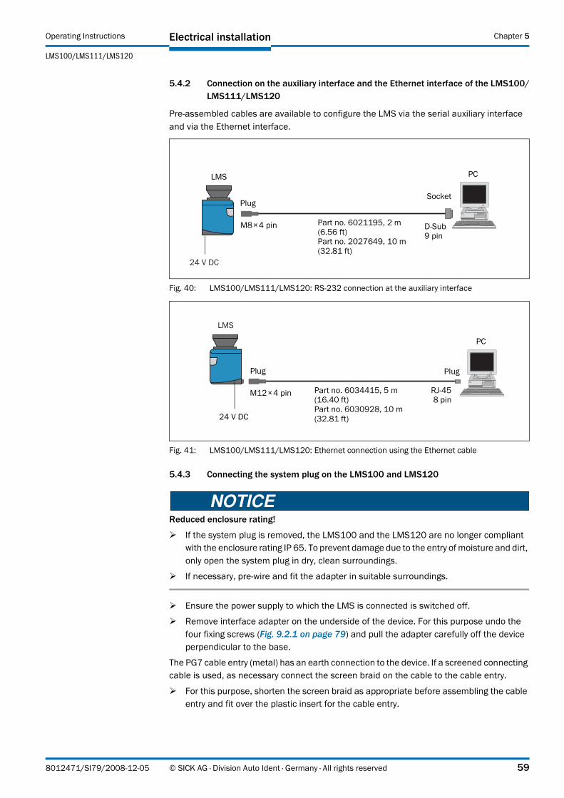
Operating Instructions
LMS100/LMS111/LMS120
Electrical installation Chapter 5
5.4.2 Connection on the auxiliary interface and the Ethernet interface of the LMS100/LMS111/LMS120
Pre-assembled cables are available to configure the LMS via the serial auxiliary interface and via the Ethernet interface.
Fig. 40: LMS100/LMS111/LMS120: RS232 connection at the auxiliary interface
Fig. 41: LMS100/LMS111/LMS120: Ethernet connection using the Ethernet cable
5.4.3 Connecting the system plug on the LMS100 and LMS120
Reduced enclosure rating!
If the system plug is removed, the LMS100 and the LMS120 are no longer compliant with the enclosure rating IP 65. To prevent damage due to the entry of moisture and dirt, only open the system plug in dry, clean surroundings.
If necessary, pre-wire and fit the adapter in suitable surroundings.
Ensure the power supply to which the LMS is connected is switched off.
Remove interface adapter on the underside of the device. For this purpose undo the four fixing screws (Fig. 9.2.1 on page 79) and pull the adapter carefully off the device perpendicular to the base.
The PG7 cable entry (metal) has an earth connection to the device. If a screened connecting cable is used, as necessary connect the screen braid on the cable to the cable entry.
For this purpose, shorten the screen braid as appropriate before assembling the cable entry and fit over the plastic insert for the cable entry.
24 V DC
PlugSocket
DSub 9 pin
M8×4 pin Part no. 6021195, 2 m (6.56 ft)Part no. 2027649, 10 m (32.81 ft)
LMS PC
LMS
24 V DC
M12×4 pin RJ458 pin
Plug
Part no. 6034415, 5 m (16.40 ft)Part no. 6030928, 10 m (32.81 ft)
Plug
PC
8012471/SI79/2008-12-05 © SICK AG · Division Auto Ident · Germany · All rights reserved 59

Electrical installation Operating Instructions
LMS100/LMS111/LMS120 Laser Measurement Systems
Chapter 5
1. Undo fitting for the PG7 cable entry.
2. Pull the cable for supply voltage and switching outputs with maximum outside diameter ∅ 5.6 mm (0.22 in) through the plastic insert for the PG7 cable entry.
3. Connect electrically isolated wires to the terminal block.
4. If necessary, connect screen braid on the cable to the cable entry.
5. Fit PG7 cable entry fitting and tighten.
6. Carefully re-fit the system plug to the LMS.
7. Tighten the fixing screws for the system plug.
5.4.4 Connecting the round M12 plug connector on the LMS111
Only make connection to the LMS111 at the round M12 plug connectors provided for this purpose!
Only use plug connectors that are compliant with enclosure rating IP 67.
Pre-assembled cables are available as accessories for the connection to the round M12 plug connectors. These comprise the round plug connector and 5, 10 or 20 m (16.40, 32.81 or 65.62 ft) of cable with flying leads.
Connection of the voltage supply on the LMS111
Pre-assembled cables with flying leads are available for the supply to the LMS111.
Fig. 42: LMS111: connection of the voltage supply
Important On the connecting cables part no. 6036159, part no. 6036160 and part no. 6036161 the cables for GND and GND heat. are either blue and black or yellow and green.
LMS
M12×5 pin Blue or yellow = GND
Brown = Vs
Part no. 6036159, 5 m (16.40 ft)Part no. 6036160, 10 m (32.81 ft)
Socket
Black or green = GND heat.
White = Vs heating
60 © SICK AG · Division Auto Ident · Germany · All rights reserved 8012471/SI79/2008-12-05

Operating Instructions
LMS100/LMS111/LMS120
Electrical installation Chapter 5
“RS232” connection on the LMS111
Fig. 43: LMS111: “RS232” connection
“I/O” connection on the LMS111
Fig. 44: LMS111: “I/O” connection
5.4.5 Wiring of inputs and outputs on the LMS
Connecting digital inputs as non-floating
Fig. 45: Connecting digital inputs as non-floating
Important The inputs require a switching voltage of at least 11 V. For this reason the supply voltage must be at least 11 V.
LMS
M12×8 pin
Yellow = CAN_L
Brown = TxD
Part no. 6036153, 5 m (16.40 ft)Part no. 6028420, 10 m (32.81 ft)
Socket
Grey = GND CAN
White = RxD
Green = CAN_H
Pink = IN1
Red = IN GND
Blue = IN2
LMS
M12×8 pin
Yellow = OUT1_A
Brown = A1_INCA_90
Part no. 6036155, 5 m (16.40 ft)Part no. 6036156, 10 m (32.81 ft)
Plug
Grey = OUT2_A
White = A1_INCA_0
Green = GNDINC_A
Pink = OUT3_A
Red = OUTx_R
Blue = OUTx_B
LMS
IN1
IN1 GND
GND
VS 11 V … 30 V
External switch
8012471/SI79/2008-12-05 © SICK AG · Division Auto Ident · Germany · All rights reserved 61
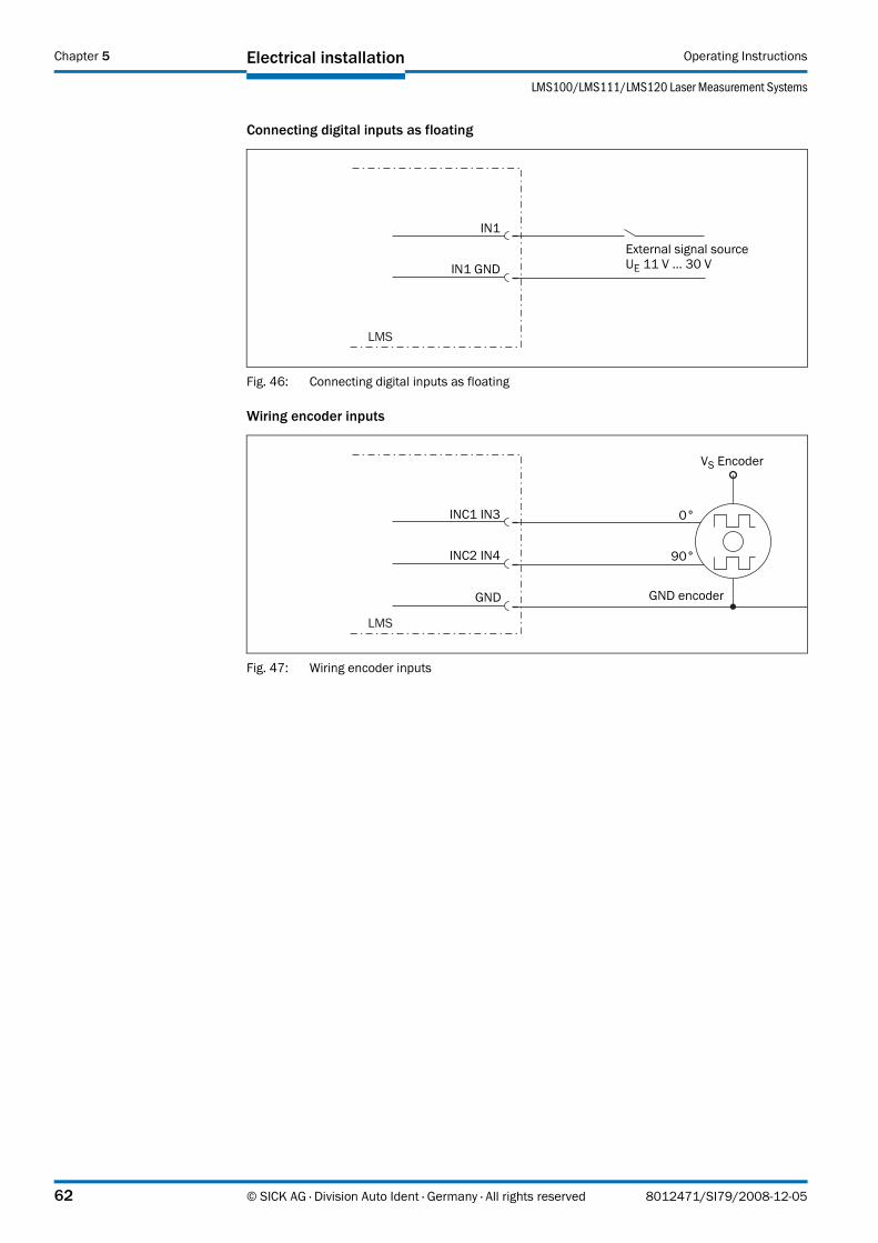
Electrical installation Operating Instructions
LMS100/LMS111/LMS120 Laser Measurement Systems
Chapter 5
Connecting digital inputs as floating
Fig. 46: Connecting digital inputs as floating
Wiring encoder inputs
Fig. 47: Wiring encoder inputs
LMS
IN1
IN1 GNDExternal signal sourceUE 11 V … 30 V
LMS
INC1 IN3
INC2 IN4
GND
VS Encoder
GND encoder
0°
90°
62 © SICK AG · Division Auto Ident · Germany · All rights reserved 8012471/SI79/2008-12-05

Operating Instructions
LMS100/LMS111/LMS120
Electrical installation Chapter 5
Connection of the outputs to a PLC, non-floating
Fig. 48: Connection of the outputs to a PLC, non-floating (active high)
Fig. 49: Connection of the outputs to a PLC, non-floating (active low)
Connection of the outputs to a PLC, floating
Fig. 50: Connection of the outputs to a PLC, floating (active high)
Fig. 51: Connection of the outputs to a PLC, floating (active low)
LMS
OUT1_A
OUT1_R
PLC
IN
OUT1_B+24 VDC
LMS
OUT1_A
OUT1_R
PLC
IN
OUT1_B+24 VDC
LMS
OUT1_A
OUT1_R
PLC
IN
OUT1_B+24 VDC
LMS
OUT1_A
OUT1_R PLC
IN
OUT1_B
+24 VDC
8012471/SI79/2008-12-05 © SICK AG · Division Auto Ident · Germany · All rights reserved 63

Electrical installation Operating Instructions
LMS100/LMS111/LMS120 Laser Measurement Systems
Chapter 5
Connection to an object protection system
Fig. 52: Connection to an object protection system
Fig. 53: Connection to an object protection system, resistance monitored
Important Between OUTx_R and OUTx_A a resistor of 10 kΩ is fitted. You can modify this to suit the external connection layout.
Wiring CAN interface
To wire the CAN interface a screened “twisted-pair” cable is required. The terminator of 120 must be connected.
Pay attention to max. cable length as per section 5.3.3 “General conditions for the data interface” on page 58.
Fig. 54: Wiring of the CAN interface
LMS
OUT1_A
OUT1_R
INOUT1_B
+24 VDC
IN
Object protection system
LMS
OUT1_A
OUT1_R
INOUT1_B
+24 VDC
IN
Object protection system
64 © SICK AG · Division Auto Ident · Germany · All rights reserved 8012471/SI79/2008-12-05
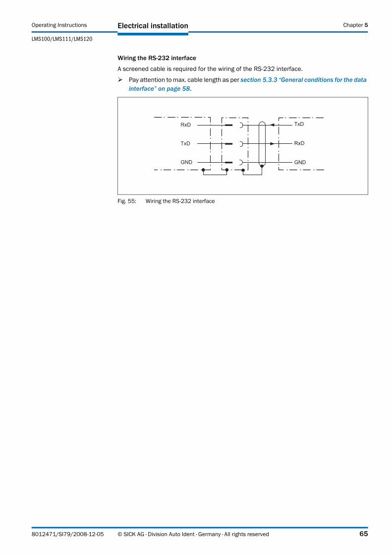
Operating Instructions
LMS100/LMS111/LMS120
Electrical installation Chapter 5
Wiring the RS232 interface
A screened cable is required for the wiring of the RS232 interface.
Pay attention to max. cable length as per section 5.3.3 “General conditions for the data interface” on page 58.
Fig. 55: Wiring the RS232 interface
8012471/SI79/2008-12-05 © SICK AG · Division Auto Ident · Germany · All rights reserved 65

Commissioning and configuration Operating Instructions
LMS100/LMS111/LMS120 Laser Measurement Systems
Chapter 6
6 Commissioning and configuration
Commissioning requires a thorough check by qualified personnel!
Before you operate a system equipped with the LMS for the first time, make sure that the system is first checked and released by qualified personnel. On this issue, observe the notes in chapter 2 “For your safety” on page 11.
Commissioning, configuration and diagnostics are undertaken using the SOPAS ET configuration software supplied.
6.1 Overview of the commissioning steps
• install SOPAS ET configuration software
• establish communication with the LMS
• create a custom parameter set using SOPAS ET and save in non-volatile memory in the LMS
• test LMS for correct function
6.2 SOPAS ET configuration software
The interactive configuration is carried out using SOPAS ET. Using this configuration software, you can configure and test the measurement properties, the analysis behaviour and the output properties of the system as required. The configuration data can be saved as a parameter set (project file) on the PC and archived.
Help for the program user interface as well as for the different options can be found in SOPAS ET:
• menu HELP, HELP F1: comprehensive online help for the program interface and the different options
• HELP window (on the bottom left in the program user interface): context sensitive help for the visible dialog
• tool tips: Move the mouse pointer over an input field. A short text (“tool tip”) with information about valid entries appears.
Primary functions are:
• selection of the menu language (German/English)
• establishment of the communication with the LMS
• password-protected configuration with different operating levels
• system diagnostics
6.2.1 System requirements for SOPAS ET
• standard Intel Pentium PC or compatible, at least Pentium III, 500 MHz
• minimum 256 MB RAM, 512 MB RAM recommended
• data interface RS232, Ethernet or CAN (see also section 5.3.3 “General conditions for the data interface” on page 58)
• operating system: MS Windows 2000, XP or VISTA
• monitor with 256 colours minimum, 65.536 colours recommended (16 Bit High Color)
66 © SICK AG · Division Auto Ident · Germany · All rights reserved 8012471/SI79/2008-12-05

Operating Instructions
LMS100/LMS111/LMS120
Commissioning and configuration Chapter 6
• screen resolution at least 800 × 600
• hard disc: minimum 170 MB free memory
• CD-ROM drive
• HTML browser on PC, e.g. Internet Explorer™, for the online help system for SOPAS ET
6.2.2 Installation of SOPAS ET
1. Start PC and insert installation CD.
2. If the installation does not start automatically, run the file setup.exe on the CD-ROM.
3. To complete the installation, follow the instructions.
6.2.3 SOPAS ET default setting
6.3 Establish communication with the LMS
Important For communication via TCPIP, the TCPIP protocol must be active on the PC.
On the connection of PC/host, following this sequence:
1. Switch on the PC.
2. Connect the PC to the LMS using data cable.
3. Switch on the supply voltage for the LMS.The LMS performs a self-test and initialises itself.
6.3.1 Connect the data interfaces
Connect PC and LMS together as per table.
6.3.2 Starting SOPAS ET and opening the scan assistant
1. Start SOPAS ET.By default SOPAS ET opens the program window with the English user interface.
2. To change the language setting, in the start dialog box click CANCEL and using the menu TOOLS, OPTIONS change the language for the user interface to GERMAN/DEUTSCH.
Parameter ValueLanguage for the user interface English (the software must be re-started after a
change)Units of length MetricUser group (operating level) Machine operatorDownload of the parameters to the LMS Immediate on change, temporary in the LMS RAMUpload of the parameters from the LMS After switching online, automaticWindow layout 3 (project tree, help, working area)Serial communication COM1: 9,600 Bd/19,200 Bd, 8 data bits, no parity,
1 stop bit
Tab. 23: SOPAS ET default setting
Data interface CommentEthernet Connect the PC to the LMS using the Ethernet cable (see Fig. 41 on
page 59)Or:RS232 Connect the PC (serial interface) to the LMS (see Fig. 40 on page 59)
Tab. 24: Connect the data interfaces
8012471/SI79/2008-12-05 © SICK AG · Division Auto Ident · Germany · All rights reserved 67

Commissioning and configuration Operating Instructions
LMS100/LMS111/LMS120 Laser Measurement Systems
Chapter 6
3. If the language setting has been modified, quit SOPAS ET and re-start.
4. In the dialog box, choose the option CREATE NEW PROJECT and confirm with OK.
5. In the main window in SCAN ASSISTANT click the CONFIGURATION button.The SCAN ASSISTANT dialog box appears.
6.3.3 Configuring the serial connection
1. In the SCAN ASSISTANT dialog box, under SERIAL CONNECTION, STANDARD PROTOCOL, activate the ACTIVATE SERIAL COMMUNICATION checkbox.
2. Click ADVANCED... button.
3. In COLA DIALECT choose the BINARY option.
4. Choose following PORT SETTINGS: 8 data bits, no parity, 1 stop bit.
5. Confirm the settings with OK.The ADVANCED SCAN SETTINGS dialog box is closed.
6. Confirm the settings in the SCAN ASSISTANT dialog box with OK.The SCAN ASSISTANT dialog box is closed.
6.3.4 Configuring the Ethernet connection
Important Deactivate all programs on your PC/notebook that access Ethernet or TCP/IP.
1. In the SCAN ASSISTANT dialog, under INTERNET PROTOCOL, IP COMMUNICATION, select the ACTIVATE IP COMMUNICATION checkbox and the USE AUTOIP checkbox.
2. Confirm the settings in the SCAN ASSISTANT dialog box with OK.The SCAN ASSISTANT dialog box is closed.
6.3.5 Performing scan
1. In the SCAN ASSISTANT dialog box, click on the START SCAN button.
2. Choose devices listed and accept using ADD DEVICE.A scan is performed for devices connected via the connection. SOPAS ET adds the devices found to the project tree and uploads the actual parameter set from the device.
6.4 Initial commissioning
The LMS is adapted to the local measurement situation using SOPAS ET. For this purpose a custom parameter set is created using SOPAS ET. The parameter set can either be loaded initially from the device (upload) or it can be prepared independently.
The parameter set is then loaded into the LMS (download). This action is performed either immediately (SOPAS ET option IMMEDIATE DOWNLOAD) or manually (SOPAS ET command DOWNLOAD ALL PARAMETERS TO THE DEVICE).
68 © SICK AG · Division Auto Ident · Germany · All rights reserved 8012471/SI79/2008-12-05

Operating Instructions
LMS100/LMS111/LMS120
Commissioning and configuration Chapter 6
Important Once the configuration has been completed, the parameter set must be saved in the non-volatile memory in the laser measurement system. In addition, the parameter set can be saved as a project file (spr file with configuration data) on the PC and archived.
Fig. 56: Principle of data storage
6.4.1 Configuring the LMS
You can configure the LMS in two ways:
• interactively using SOPAS ETThis section describes the interactive configuration.
• using configuration messagesOn this subject please read section 3.11 “Data communication using messages” on page 40.
Interactive configuration using SOPAS ET
All parameters that can be configured for the LMS are combined into a corresponding device description (jar file) for SOPAS ET. You can open this file using the device description project tree.
The function of each parameter is explained in a context-sensitive online help ([F1] key). The valid range of values and the default are listed in the PARAMETER INFO window (right mouse button when the pointer is positioned over the parameter).
Important Software access to the LMS is password protected. Following completion of the configuration, you should change the password so that it can perform its protective function.
Parameter set in the LMS RAM
Parameter set saved in non-volatile memory
Factory settings for the LMS
RAM
EEPROM
ROM
Open project file with current parameter set
RAM
Saved project file with archived parameter set (*.spr)
Hard disc
Upload
Download
LMS PC with SOPAS ET
User level PasswordMaintenance personnel mainAuthorised client client
Tab. 25: Passwords
8012471/SI79/2008-12-05 © SICK AG · Division Auto Ident · Germany · All rights reserved 69
Commissioning and configuration Operating Instructions
LMS100/LMS111/LMS120 Laser Measurement Systems
Chapter 6
Use the project tree in SOPAS ET to configure the parameters necessary for your application.
Do not switch off the voltage supply during configuration!
Switching off the voltage supply during configuration causes all parameters already configured to be lost.
1. From the OPTIONS menu select the LOGIN DEVICE command and log in to the system using the password “client” as AUTHORISED CLIENT.
2. Configure the LMS for the required application with the aid of the parameters in SOPAS ET.
Help for the program user interface as well as for the different options can be found in SOPAS ET.
Resetting configuration
Recommendation To reset the LMS to the default delivery status, you should first export the device data to a file from a device that is in the default delivery status. You can then subsequently load these device data into an already configured device to reset its configuration to the default delivery status.
6.5 Connection and test measurement
Use the graphic scan view in SOPAS ET to verify the generated measured values and to verify the measurement area online.
1. In the project tree, choose LMS100_FIELDEVAL, MONITOR, SCAN VIEW.
2. In order to start the measurement, click on PLAY.
3. Compare the measurement line with the desired result.
Important – The SCAN VIEW in the MONITOR is dependent on the available computing power of the PC and is not output in real-time. For this reason not all measured values are displayed. The same limitation also applies when saving measured values displayed in a file.
– The monitor displays the measured values unfiltered, i.e. the action of filters can not be checked with the aid of the monitor.
4. After completing the test measurement successfully, save the configuration permanently to the LMS: menu LMS100_FIELDEVAL, PARAMETER, SAVE PERMANENT.
70 © SICK AG · Division Auto Ident · Germany · All rights reserved 8012471/SI79/2008-12-05
Operating Instructions
LMS100/LMS111/LMS120
Maintenance Chapter 7
7 Maintenance
Claims under the warranty rendered void!
The housing screws of the LMS are sealed. Claims under the warranty against SICK AG will be rendered void if the seals are damaged or the device opened. The housing is only allowed to be opened by authorised service personnel.
7.1 Maintenance during operation
7.1.1 Cleaning the optics cover
The LMS laser measurement system is largely maintenance-free. The optics cover on the laser measurement system should however be cleaned regularly and if it is contaminated.
Do not use aggressive detergents.
Do not use abrasive cleaning agents.
Important Static charges cause dust particles to be attracted to the optics cover. You reduce this effect by using the antistatic plastic cleaner (SICK part no. 5600006) and the SICK lens cloth (part no. 4003353) (see section 10.3.2 “Available accessories” on page 101).
How to clean the optics cover:
Use a clean and soft brush to remove dust from the optics cover.
Then wipe the view window of the optics cover with a clean and damp cloth.
7.2 Exchanging an LMS
As all external cable connections end in the system plug or in the plug connectors, it is not necessary to re-install the device electrically on a device replacement. The replacement unit can then be simply connected.
If the LMS is to be replaced, proceed as follows:
1. Switch off the voltage supply for the LMS.
2. Remove the connection cable/s from the LMS.
3. Mount the replacement device (see chapter 4 “Mounting” on page 44).
4. Configuring a replacement device (see chapter 6 “Commissioning and configuration” on page 66).
8012471/SI79/2008-12-05 © SICK AG · Division Auto Ident · Germany · All rights reserved 71

Troubleshooting Operating Instructions
LMS100/LMS111/LMS120 Laser Measurement Systems
Chapter 8
8 Troubleshooting
Claims under the warranty rendered void!
The housing screws of the LMS are sealed. Claims under the warranty against SICK AG will be rendered void if the seals are damaged or the device opened. The housing is only allowed to be opened by authorised service personnel.
This chapter describes how to identify and rectify errors and malfunctions of the LMS.
8.1 In the event of faults or errors
Cease operation if the cause of the malfunction has not been clearly identified!
Stop the machine/system if you cannot clearly identify or allocate the error and if you cannot safely rectify the malfunction.
8.2 Error displays of the LEDs
Display Possible cause Rectification of the error
and off No operating voltage, or voltage too low
Check the voltage supply and activate, if necessary.
illuminatedOptics cover contaminated, still in operation
Clean the optics cover.
flashes with 1 HzOptics cover contaminated, no operation
Clean the optics cover.
flashes with 4 Hz
System error Pay attention to the error display of the 7segment display or carry out a diagnostics with the aid of SOPAS ET.
Switch the device off and back on again.
Tab. 26: Error displays of the LEDs
72 © SICK AG · Division Auto Ident · Germany · All rights reserved 8012471/SI79/2008-12-05
Operating Instructions
LMS100/LMS111/LMS120
Troubleshooting Chapter 8
8.3 Indications of the 7segment display
8.4 Detailed error analysis
The LMS outputs occurring errors in various ways. Errors are output in stages and always permit detailed analysis:
• Communication errors can occur on the transfer of messages to the LMS. The LMS then returns an error code.
• In case of status errors occurring during a scan, error codes are written to a status log.
8.4.1 Field evaluation monitor
Using the field evaluation monitor, you can analyse whether and how evaluation fields are infringed and how the outputs on the LMS behave.
PROJECT TREE, LMS100_FIELDEVAL, MONITOR, FIELD EVALUATION MONITOR.
8.4.2 Field evaluation logging
Using the field evaluation logging you can log, save and subsequently play back the operation of LMS. It is used for diagnostics over extended periods and for the analysis of malfunctions or for the optimisation of processes.
PROJECT TREE, LMS100_FIELDEVAL, MONITOR, FIELD EVALUATION LOGGING.
Display Possible cause Rectification of the error
,, … No error Device in measurement mode
IDLE mode, the outputs are in the OFF state, the laser is switched off.
No error. If the criteria for the IDLE mode are withdrawn, readiness for operation is re-established.
Motor starts No error.
LMS faulty Send the LMS to the manufacturer for repair.
Tab. 27: Indications of the 7segment display
8012471/SI79/2008-12-05 © SICK AG · Division Auto Ident · Germany · All rights reserved 73
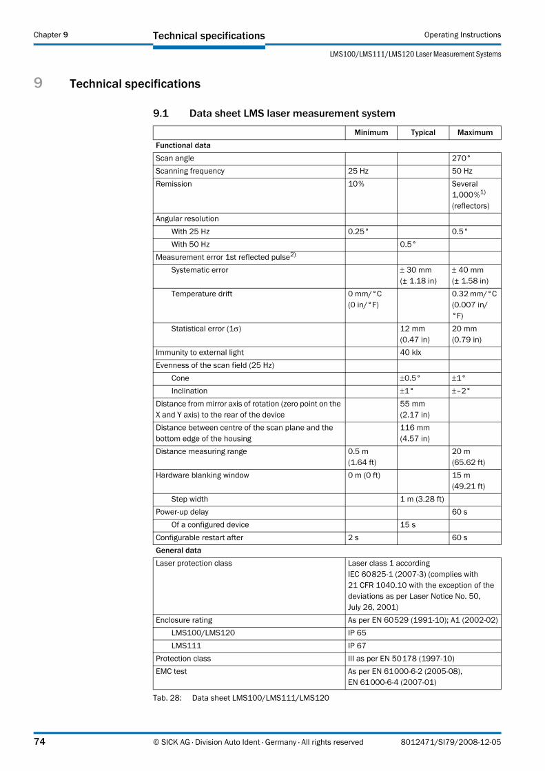
Technical specifications Operating Instructions
LMS100/LMS111/LMS120 Laser Measurement Systems
Chapter 9
9 Technical specifications
9.1 Data sheet LMS laser measurement system
Minimum Typical MaximumFunctional dataScan angle 270°Scanning frequency 25 Hz 50 HzRemission 10% Several
1,000%1) (reflectors)
Angular resolutionWith 25 Hz 0.25° 0.5°With 50 Hz 0.5°
Measurement error 1st reflected pulse2)
Systematic error ± 30 mm (± 1.18 in)
± 40 mm (± 1.58 in)
Temperature drift 0 mm/°C (0 in/°F)
0.32 mm/°C (0.007 in/°F)
Statistical error (1σ) 12 mm (0.47 in)
20 mm (0.79 in)
Immunity to external light 40 klxEvenness of the scan field (25 Hz)
Cone ±0.5° ±1°Inclination ±1° ±–2°
Distance from mirror axis of rotation (zero point on the X and Y axis) to the rear of the device
55 mm (2.17 in)
Distance between centre of the scan plane and the bottom edge of the housing
116 mm (4.57 in)
Distance measuring range 0.5 m (1.64 ft)
20 m (65.62 ft)
Hardware blanking window 0 m (0 ft) 15 m (49.21 ft)
Step width 1 m (3.28 ft)Power-up delay 60 s
Of a configured device 15 sConfigurable restart after 2 s 60 sGeneral dataLaser protection class Laser class 1 according
IEC 608251 (20073) (complies with 21 CFR 1040.10 with the exception of the deviations as per Laser Notice No. 50, July 26, 2001)
Enclosure rating As per EN 60529 (199110); A1 (200202)LMS100/LMS120 IP 65LMS111 IP 67
Protection class III as per EN 50178 (199710)EMC test As per EN 6100062 (200508),
EN 6100064 (200701)
Tab. 28: Data sheet LMS100/LMS111/LMS120
74 © SICK AG · Division Auto Ident · Germany · All rights reserved 8012471/SI79/2008-12-05

Operating Instructions
LMS100/LMS111/LMS120
Technical specifications Chapter 9
Electrical safety As per EN 50178 (199710)Operating temperature range
LMS100/LMS120 0 °C (32 °F) +50 °C (122 °F)
LMS111 –30 °C (86 °F)
+50 °C (122 °F)
Storage temperature range –30 °C (86 °F)
+70 °C (158 °F) max. 24 h
Humidity (taking into account the operating temperature range)
DIN EN 60068261, method 1
Vibration resistance As per EN 6006826 (199504)Frequency range 10 Hz 150 HzAmplitude 5 g RMS
Shock resistance As per EN 60068227 (199303), EN 60068229 (199304)
Single shock 15 g (0.53 oz), 11 ms Continuous shock 10 g (0.35 oz), 16 ms
Sender Pulsed laser diodeWave length 895 nm 905 nm 915 nmDivergence of the collimated beam (solid angle) 15 mradLight spot size at the optics cover 8 mm
(0.32 in)Light spot size at 18 m (59.05 ft) scanning range 300 mm
(11.82 in)Housing
Material GDALSI12 3.2582.05Colour LMS100/LMS120 RAL 5012 (blue)Colour LMS111 RAL 7032 (grey)Alloy Excellent weather resistance as per
DIN EN 106:1988, plate 3Optics cover
Material PolycarbonateSurface finish Outside with scratch-resistant coating
System plug (LMS100/LMS120)Material GDALSI12 3.2582.05Colour RAL 9005 (black)
Cable entries (LMS111)Material Stainless steel/plastic
Dimensions3)
Height LMS100/LMS120 152 mm (5.99 in)
Height LMS111 162 mm (6.38 in)
Width 102 mm (4.02 in)
Depth 106 mm (4.18 in)
Minimum Typical Maximum
Tab. 28: Data sheet LMS100/LMS111/LMS120
8012471/SI79/2008-12-05 © SICK AG · Division Auto Ident · Germany · All rights reserved 75
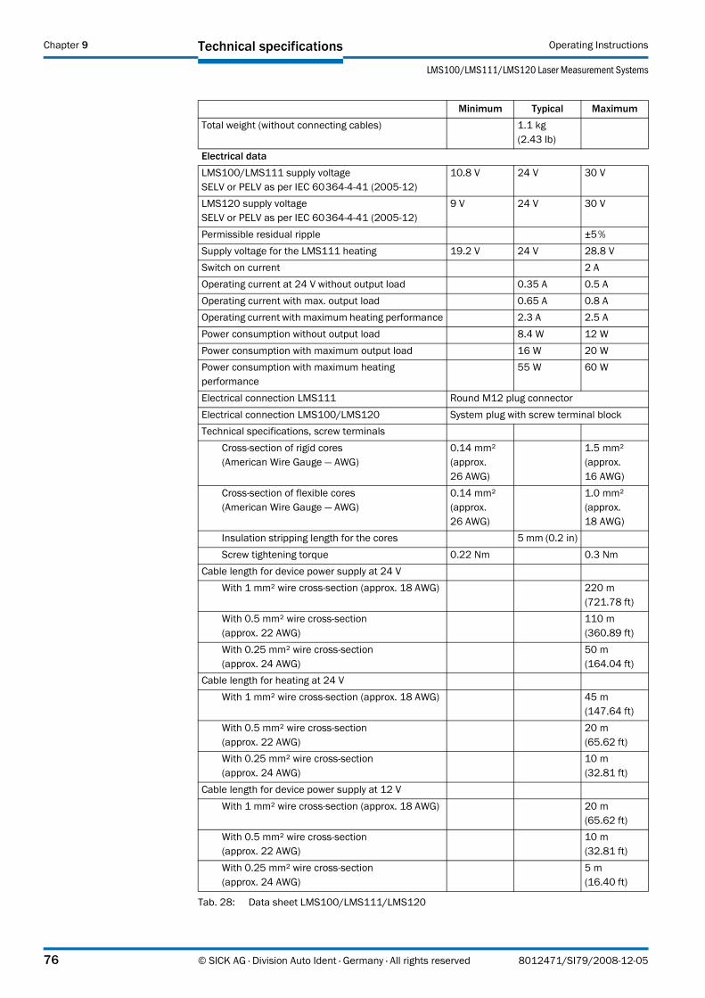
Technical specifications Operating Instructions
LMS100/LMS111/LMS120 Laser Measurement Systems
Chapter 9
Total weight (without connecting cables) 1.1 kg (2.43 lb)
Electrical dataLMS100/LMS111 supply voltageSELV or PELV as per IEC 60364441 (200512)
10.8 V 24 V 30 V
LMS120 supply voltageSELV or PELV as per IEC 60364441 (200512)
9 V 24 V 30 V
Permissible residual ripple ±5%Supply voltage for the LMS111 heating 19.2 V 24 V 28.8 VSwitch on current 2 AOperating current at 24 V without output load 0.35 A 0.5 AOperating current with max. output load 0.65 A 0.8 AOperating current with maximum heating performance 2.3 A 2.5 APower consumption without output load 8.4 W 12 WPower consumption with maximum output load 16 W 20 WPower consumption with maximum heating performance
55 W 60 W
Electrical connection LMS111 Round M12 plug connectorElectrical connection LMS100/LMS120 System plug with screw terminal blockTechnical specifications, screw terminals
Cross-section of rigid cores(American Wire Gauge — AWG)
0.14 mm² (approx. 26 AWG)
1.5 mm² (approx. 16 AWG)
Cross-section of flexible cores(American Wire Gauge — AWG)
0.14 mm² (approx. 26 AWG)
1.0 mm² (approx. 18 AWG)
Insulation stripping length for the cores 5 mm (0.2 in)Screw tightening torque 0.22 Nm 0.3 Nm
Cable length for device power supply at 24 VWith 1 mm² wire cross-section (approx. 18 AWG) 220 m
(721.78 ft)With 0.5 mm² wire cross-section (approx. 22 AWG)
110 m (360.89 ft)
With 0.25 mm² wire cross-section (approx. 24 AWG)
50 m (164.04 ft)
Cable length for heating at 24 VWith 1 mm² wire cross-section (approx. 18 AWG) 45 m
(147.64 ft)With 0.5 mm² wire cross-section (approx. 22 AWG)
20 m (65.62 ft)
With 0.25 mm² wire cross-section (approx. 24 AWG)
10 m (32.81 ft)
Cable length for device power supply at 12 VWith 1 mm² wire cross-section (approx. 18 AWG) 20 m
(65.62 ft)With 0.5 mm² wire cross-section (approx. 22 AWG)
10 m (32.81 ft)
With 0.25 mm² wire cross-section (approx. 24 AWG)
5 m(16.40 ft)
Minimum Typical Maximum
Tab. 28: Data sheet LMS100/LMS111/LMS120
76 © SICK AG · Division Auto Ident · Germany · All rights reserved 8012471/SI79/2008-12-05
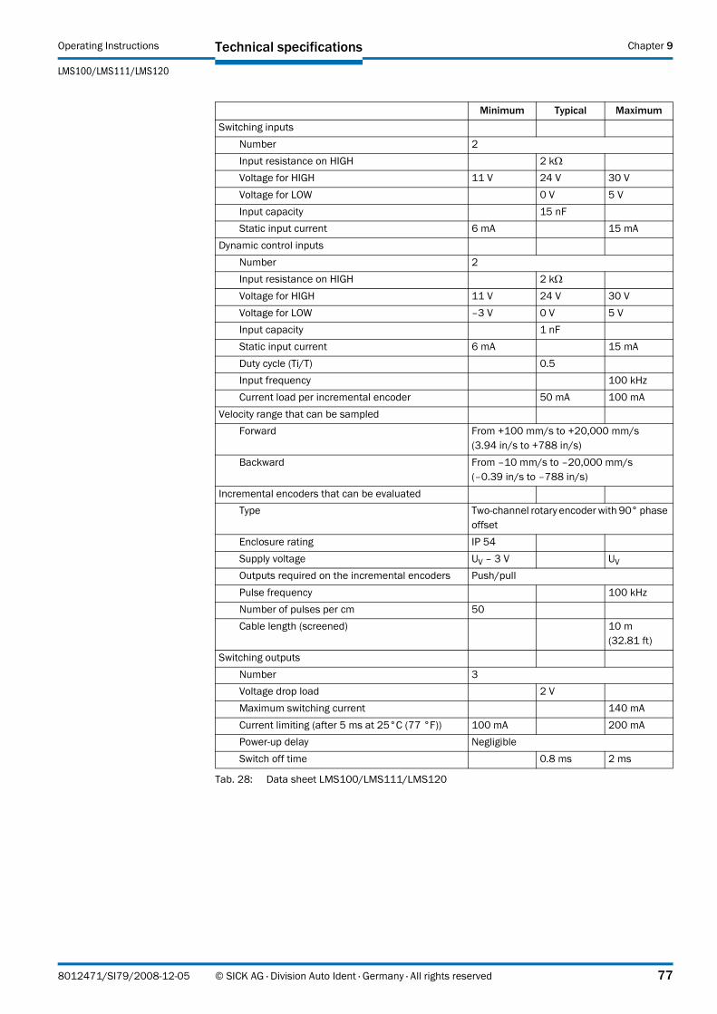
Operating Instructions
LMS100/LMS111/LMS120
Technical specifications Chapter 9
Switching inputsNumber 2Input resistance on HIGH 2 kΩVoltage for HIGH 11 V 24 V 30 VVoltage for LOW 0 V 5 VInput capacity 15 nFStatic input current 6 mA 15 mA
Dynamic control inputsNumber 2Input resistance on HIGH 2 kΩVoltage for HIGH 11 V 24 V 30 VVoltage for LOW –3 V 0 V 5 VInput capacity 1 nFStatic input current 6 mA 15 mADuty cycle (Ti/T) 0.5Input frequency 100 kHzCurrent load per incremental encoder 50 mA 100 mA
Velocity range that can be sampled Forward From +100 mm/s to +20,000 mm/s
(3.94 in/s to +788 in/s)Backward From –10 mm/s to –20,000 mm/s
(–0.39 in/s to –788 in/s)Incremental encoders that can be evaluated
Type Two-channel rotary encoder with 90° phase offset
Enclosure rating IP 54Supply voltage UV – 3 V UV
Outputs required on the incremental encoders Push/pullPulse frequency 100 kHzNumber of pulses per cm 50Cable length (screened) 10 m
(32.81 ft)Switching outputs
Number 3Voltage drop load 2 VMaximum switching current 140 mACurrent limiting (after 5 ms at 25°C (77 °F)) 100 mA 200 mAPower-up delay NegligibleSwitch off time 0.8 ms 2 ms
Minimum Typical Maximum
Tab. 28: Data sheet LMS100/LMS111/LMS120
8012471/SI79/2008-12-05 © SICK AG · Division Auto Ident · Germany · All rights reserved 77
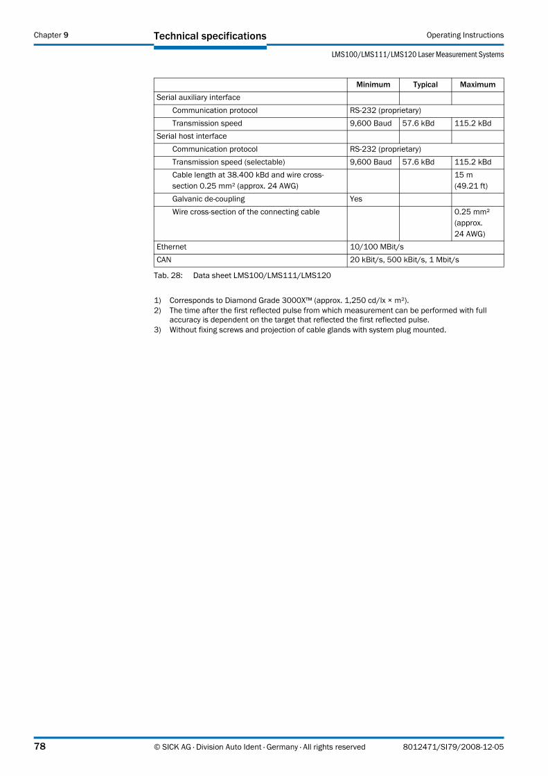
Technical specifications Operating Instructions
LMS100/LMS111/LMS120 Laser Measurement Systems
Chapter 9
Serial auxiliary interfaceCommunication protocol RS232 (proprietary)Transmission speed 9,600 Baud 57.6 kBd 115.2 kBd
Serial host interfaceCommunication protocol RS232 (proprietary)Transmission speed (selectable) 9,600 Baud 57.6 kBd 115.2 kBdCable length at 38.400 kBd and wire cross-section 0.25 mm² (approx. 24 AWG)
15 m (49.21 ft)
Galvanic de-coupling YesWire cross-section of the connecting cable 0.25 mm²
(approx. 24 AWG)
Ethernet 10/100 MBit/sCAN 20 kBit/s, 500 kBit/s, 1 Mbit/s
1) Corresponds to Diamond Grade 3000X™ (approx. 1,250 cd/lx × m²).2) The time after the first reflected pulse from which measurement can be performed with full
accuracy is dependent on the target that reflected the first reflected pulse.3) Without fixing screws and projection of cable glands with system plug mounted.
Minimum Typical Maximum
Tab. 28: Data sheet LMS100/LMS111/LMS120
78 © SICK AG · Division Auto Ident · Germany · All rights reserved 8012471/SI79/2008-12-05

Operating Instructions
LMS100/LMS111/LMS120
Technical specifications Chapter 9
9.2 Dimensional drawings
9.2.1 Dimensional drawing LMS100/LMS120
Fig. 57: Dimensional drawing LMS100/LMS120
Min. 15
116
23.8
Max
.200
270°
105
8
19
10.5
49
79.3
M5
×7.
5
7394
152115.7
79.3
All dimensions in mm
mm inM5×7.5 M5×0.38 0.3110.5 0.4115 0.5919 0.7523.8 0.9449 1.9373 2.8779.3 3.1294 3.7105 4.13115.7 4.56116 4.57152 5.98200 7.87
8012471/SI79/2008-12-05 © SICK AG · Division Auto Ident · Germany · All rights reserved 79

Technical specifications Operating Instructions
LMS100/LMS111/LMS120 Laser Measurement Systems
Chapter 9
9.2.2 Dimensional drawing LMS111
Fig. 58: Dimensional drawing LMS111
Max
.200
Min. 15
All dimensions in mm
116
23.8
270°
105
10.5
49
79.3 10
M5
×7.
5
7394
152115.7
79.3
mm inM5×7.5 M5×0.310 0.3910.5 0.4115 0.5923.8 0.9449 1.9373 2.8779.3 3.1294 3.7105 4.13115.7 4.56116 4.57152 5.98200 7.87
80 © SICK AG · Division Auto Ident · Germany · All rights reserved 8012471/SI79/2008-12-05

Operating Instructions
LMS100/LMS111/LMS120
Technical specifications Chapter 9
9.2.3 Dimensional drawings, mounting kits
Fig. 59: Dimensional drawing, mounting kit 1a (mm)
Fig. 60: Dimensional drawing, mounting kit 1b (mm)
73
4 DIN 74F5
120
21.9
16
74.7
4915.7
15.9
All dimensions in mm
Part number 2034324
mm in4 0.1615.7 0.6215.9 0.6316 0.6321.9 0.8649 1.9373 2.8774.7 2.94120 4.72
Part number 2034325
21.9
16
74.7
4915.7
15.9
73
4
DIN 74F5
120
78
102.
5
109.6
∅ 100
48
All dimensions in mmmm in4 0.1615.7 0.6215.9 0.6316 0.6321.9 0.8648 1.8949 1.9373 2.8774.7 2.9478 3.07100 3.94102.5 4.04109.6 4.31120 4.72
8012471/SI79/2008-12-05 © SICK AG · Division Auto Ident · Germany · All rights reserved 81

Technical specifications Operating Instructions
LMS100/LMS111/LMS120 Laser Measurement Systems
Chapter 9
Fig. 61: Dimensional drawing, mounting kit 2 (mm)
Fig. 62: Dimensional drawing, mounting kit 3 (mm)
Part number 2039302
4
18
33.4
37.7
139.4
118.51819
.7
19.7
78.2
130
40.7
All dimensions in mmmm in4 0.1618 0.7119.7 0.7833.4 1.3137.7 1.4840.7 1.678.2 3.08118.5 4.67130 5.12139.4 5.49
Part number 2039303
158.8
150
130
20.5
5
41
All dimensions in mmmm in5 0.220.5 0.8141 1.61130 5.12150 5.91158.8 6.25
82 © SICK AG · Division Auto Ident · Germany · All rights reserved 8012471/SI79/2008-12-05

Operating Instructions
LMS100/LMS111/LMS120
Technical specifications Chapter 9
9.2.4 Dimensional drawings, weather protection hoods
Fig. 63: Dimensional drawing weather protection hood 190°
Fig. 64: Dimensional drawing weather protection hood 270°
Part number 2046459
114
347.5
174.6
44
R205
All dimensions in mm
261.5 40
mm in40 1.5744 1.73114 4.49174.6 6.87R205 R8.07261.5 10.3347.5 13.68
Part number 2046458
114
347.5
174.6
44
R205
All dimensions in mm
360.340
90°
mm in40 1.5744 1.73114 4.49174.6 6.87R205 R8.07347.5 13.68360.3 14.19
8012471/SI79/2008-12-05 © SICK AG · Division Auto Ident · Germany · All rights reserved 83

Annex Operating Instructions
LMS100/LMS111/LMS120 Laser Measurement Systems
Chapter 10
10 Annex
10.1 Overview of the annexes
The annex contains the following supplementary information:
• message descriptions
• ordering information
• glossary
• illustration containing the EU Declaration of Conformity
10.2 Messages
Notation
The individual message sections are each to be separated by a space (ASCII code 32, 20h). The LMS interprets the parameters transferred as follows:
• Parameters with a leading “+” or “–” are interpreted as a decimal value (ASCII notation).
• Parameters without a leading “+” or “–” are interpreted as a hexadecimal value (ASCII notation).
• The LMS interprets each parameter individually, i.e. the different notations can be mixed within a message.
• All examples used in the following message lists refer to the CoLa-A protocol.
Variable types
The variable types are given in the message syntax. The following variable types are possible:
Important • The information in the “Length” column of the table refers to the binary transfer of the numeric parameters.
• The information in the “Value range” column in the table refers to the value range mathematically possible for the variable type. The actual value ranges for the parameters may be different. You will find these in the message syntax that follows.
Variable type Length (byte) Value range Signbool_1 1 0 or 1 Nouint_8 1 0 … 255 Noint_8 1 –128 … +127 Yesuint_16 2 0 … 65,535 Noint_16 2 –32,768 … +32,767 Yesuint_32 4 0 … 4,294,967,295 Noint_32 4 –2,147,483,648 … +2,147,483,647 Yesfloat_32 4 ±~10–44.85 … +1038.53 Yesstring Context-dependent Important: strings are not terminated in
zeroes
Tab. 29: Variable types
84 © SICK AG · Division Auto Ident · Germany · All rights reserved 8012471/SI79/2008-12-05

Operating Instructions
LMS100/LMS111/LMS120
Annex Chapter 10
10.2.1 Start measurement
The LMS starts measuring.
Request
Message structure: sMN LMCstartmeas
Answer
Message structure: sAN LMCstartmeas ErrorCode
Example
Request: sMN LMCstartmeas
Answer: sAN LMCstartmeas 0
Message part Description Variable type Length (byte)
Value range
Type of command Request (SOPAS method by name) string 3 sMNCommand Start measurement string 12 LMCstartmeas
Message syntax I: Request “Start measurement”
Message part Description Variable type Length (byte)
Value range
Type of command Answer (SOPAS answer) string 3 sANCommand Start measurement string 12 LMCstartmeasErrorCode The command has been accepted
if the error code 0 is returned.Enum8 1 0 no error
1 error, status change not permitted
Message syntax II: Answer to the “Start measurement” request
8012471/SI79/2008-12-05 © SICK AG · Division Auto Ident · Germany · All rights reserved 85

Annex Operating Instructions
LMS100/LMS111/LMS120 Laser Measurement Systems
Chapter 10
10.2.2 Query status
Returns the status of the LMS.
Important Only when the status 7 = “Ready for measurement” is achieved can measured data be requested from the LMS.
Request
Message structure: sRN STlms
Answer
Message structure: sRA STlms Status OperatingTemperatureRange Time Date [LED1 LED2 LED3]
Example
Request: sRN STlms
Answer: sRA STlms 7 0 8 00:00:00 8 01.01.06 0 0 0
Message part Description Variable type Length (byte)
Value range
Type of command Request (SOPAS read by name) string 3 sRNCommand Query status string 5 STlms
Message syntax III: Request “Query status”
Message part Description Variable type Length (byte)
Value range
Type of command Acknowledgement of receipt (SOPAS read answer)
string 3 sRA
Command Query status string 5 STlms Status Status of the LMS Enum16 1 0 undefined
1 initialisation2 configuration3 IDLE4 rotated5 in preparation6 ready7 ready for
measurement8 … 11 reserved
Operating temperature range Indicates whether the operating temperature range is met or not
bool_1 1 0 yes1 no
Time Flexible range, the string can contain 0 to 10 characters
string 0 … 10 ................
Date Flexible range, the string can contain 0 to 10 characters
string 0 … 10 ................
LED
s
LED1 Currently without function, values always 0
uint_32 4 0 reservedLED2 uint_32 4 0 reservedLED3 uint_32 4 0 reserved
Message syntax IV: Answer to the “Query status” request
86 © SICK AG · Division Auto Ident · Germany · All rights reserved 8012471/SI79/2008-12-05

Operating Instructions
LMS100/LMS111/LMS120
Annex Chapter 10
10.2.3 Read scan data
The measured value output is started using this message. It is a prerequisite for this action that the LMS is in the “Measurement” status. For this purpose the measurement mode must be started, there are two ways you can undertake this action:
• start via SOPAS ET
PROJECT TREE, LMS100_FIELDEVAL, PARAMETER, BASIC PARAMETERS, area MEASUREMENT.
• start via message (see section 10.2.1 “Start measurement” on page 85)
Single or continuous measured value output
There are two ways of requesting measured value output (see section 3.7.3 “Measured value output” on page 28):
• Exactly one measured value message can be requested using the sRN LMDscandata message — the last scan measured is transferred.
• Measured data can be continuously requested using the sEN LMDscandata message — measured data are then transferred until the measured value output is stopped using the sEN LMDscandata message.
Request method 1
Message structure: sRN LMDscandata
Request method 2
Message structure: sEN LMDscandata MeasurementStartStop
Message structure: sRA/sSN LMDscandata VersionNumber DeviceNumber SerialNumber DeviceStatus MessageCounter ScanCounter PowerUpDuration TransmissionDuration InputStatus OutputStatus ReservedByteA ScanningFrequency MeasurementFrequency NumberEncoders [EncoderPosition EncoderSpeed] NumberChannels16Bit [MeasuredDataContent ScalingFactor ScalingOffset StartingAngle AngularStepWidth NumberData [Data_1 Data_n]] NumberChannels8Bit [MeasuredDataContent ScalingFactor ScalingOffset StartingAngle AngularStepWidth [NumberData Data_1 Data_n] Position [XPosition YPosition ZPosition XRotation YRotation ZRotation RotationType] Name
Message part Description Variable type Length (byte)
Value range
Type of command Request (SOPAS read by name) string 3 sRNCommand Data request string 11 LMDscandata
Message syntax V: Request “Read scan data”
Message part Description Variable type Length (byte)
Value range
Type of command Request (SOPAS event by name) string 3 sENCommand Data request string 11 LMDscandataMeasurementStartStop Enum8 1 0 stop of the measured
value output1 start of the measured
value output
Message syntax VI: Request “Read scan data”
8012471/SI79/2008-12-05 © SICK AG · Division Auto Ident · Germany · All rights reserved 87
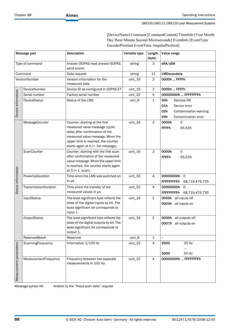
Annex Operating Instructions
LMS100/LMS111/LMS120 Laser Measurement Systems
Chapter 10
[DeviceName] Comment [CommentContent] TimeInfo [Year Month Day Hour Minute Second Microseconds] EventInfo [EventType EncoderPosition EventTime AngularPosition]
Message part Description Variable type Length (byte)
Value range
Type of command Answer (SOPAS read answer/SOPAS send event)
string 3 sRA/sSN
Command Data request string 11 LMDscandataVersionNumber Version information for the
measured datauint_16 2 0000h … FFFFh
Dev
ice
info
rmat
ion DeviceNumber Device ID as configured in SOPAS ET uint_16 2 0000h … FFFFh
Serial number Factory serial number uint_32 4 00000000h … FFFFFFFFhDeviceStatus Status of the LMS uint_8 1 00h Devices OK
01h Device error 02h Contamination warning 04h Contamination error
Stat
usin
form
atio
n
MessageCounter Counter, starting at the first measured value message (cyclic data) after confirmation of the measured value message. When the upper limit is reached, the counter starts again at 0 (= 1st message).
uint_16 2 0000h 0FFFFh 65,535
ScanCounter Counter, starting with the first scan after confirmation of the measured value message. When the upper limit is reached, the counter starts again at 0 (= 1. scan).
uint_16 2 0000h 0FFFFh 65,535
PowerUpDuration Time since the LMS was switched on in µs
uint_32 4 00000000h 0FFFFFFFFFh 68,719,476,735
TransmissionDuration Time since the transfer of the measured values in µs
uint_32 4 00000000h 0FFFFFFFFFh 68,719,476,735
InputStatus The least significant byte reflects the state of the digital inputs by bit. The least significant bit corresponds to input 1.
uint_16 2 0000h all inputs off0003h all inputs on
OutputStatus The least significant byte reflects the state of the digital outputs by bit. The least significant bit corresponds to output 1.
uint_16 2 0000h all outputs off0007h all outputs on
ReservedByteA Reserved uint_8 1 –
Mea
sure
men
tpar
amet
ers ScanningFrequency Information 1/100 Hz uint_32 4 2500 25 Hz
…5000 50 Hz
MeasurementFrequency Frequency between two separate measurements in 100 Hz
uint_32 4 00000000h … FFFFFFFFh
Message syntax VII: Answer to the “Read scan data” request
88 © SICK AG · Division Auto Ident · Germany · All rights reserved 8012471/SI79/2008-12-05

Operating Instructions
LMS100/LMS111/LMS120
Annex Chapter 10
NumberEncoders Defines the number of encoders from which data are output
Enum8 1 1…3 1 to 3 encoder
Enco
der EncoderPosition Information in ticks uint_32 4 00000000h … FFFFFFFFh
EncoderSpeed Information in ticks/mm uint_16 2 0000h … FFFFh
NumberChannels16Bit Defines the number of 16-bit output channels on which measured data are output
Enum8 1 1 … 4 1 to 4 output channels
Outp
utch
anne
l1…
4(1
6bi
t)
MeasuredDataContent The message part defines the contents of the output channel.
string 5 DIST1 Radial distance for the first reflected pulse
RSSI1 Remission values for the first reflected pulse
DIST2 Radial distance for the second reflected pulse
RSSI2 Remission values for the second reflected pulse
ScalingFactor Multiplier for the values in the message parts Data_1 to Data_n
Real 4 00000000h … FFFFFFFFh
ScalingOffset For the LMS always 0 Real 4 00000000h … FFFFFFFFhStarting angle Information 1/10,000 degree int_32 4 –550,000 … +1,250,000Angular step width Information 1/10,000 degree uint_16 2 1,000 … 10,000NumberData Defines the number of items of
measured data outputuint_16 2 0 … 1,082
Data_1 Output of the measured values 1 to n. The contents and the unit depend on the message part “MeasuredDataContent”.DIST in mm, RSSI in digits
uint_16 2 0000h … FFFFhData_n uint_16 2 0000h … FFFFh
NumberChannels8Bit Defines the number of 8-bit output channels on which measured data are output
Enum8 1 1 … 4 1 to 4 output channels
Outp
utch
anne
l1…
4m
easu
red
data
(8bi
t)
MeasuredDataContent The message part defines the contents of the message parts that follow.
string 5 RSSI1 Remission values for the first reflected pulse
RSSI2 Remission values for the second reflected pulse
ScalingFactor Multiplier for the values in the message parts Data_1 to Data_n
Real 4 00000000h … FFFFFFFFh
ScalingOffset For the LMS always 0 Real 4 00000000h … FFFFFFFFhStarting angle Information 1/10,000 degree int_32 4 550000 … 1250000Angular step width Information 1/10,000 degree uint_16 2 1000 … 10000NumberData Defines the number of items of
measured data outputuint_16 2 0 … 1082
Data_1 Output of the measured values 1 to n. The contents and the unit depend on the message part “MeasuredDataContent”.RSSI in digits
uint_8 1 00h … FFhData_n uint_8 1 00h … FFh
Message part Description Variable type Length (byte)
Value range
Message syntax VII: Answer to the “Read scan data” request
8012471/SI79/2008-12-05 © SICK AG · Division Auto Ident · Germany · All rights reserved 89

Annex Operating Instructions
LMS100/LMS111/LMS120 Laser Measurement Systems
Chapter 10
Position Defines whether position data are output
Enum8 1 0 no position data1 Output of position data
Posi
tion
info
rmat
ion
XPosition X coordinate for the LMS in a coordinate system
Real 4 00000000h … FFFFFFFFh
YPosition Y coordinate for the LMS in a coordinate system
Real 4 00000000h … FFFFFFFFh
ZPosition Z coordinate for the LMS in a coordinate system
Real 4 00000000h … FFFFFFFFh
XRotation X angle of rotation for the LMS in a coordinate system
Real 4 00000000h … FFFFFFFFh
YRotation Y angle of rotation for the LMS in a coordinate system
Real 4 00000000h … FFFFFFFFh
ZRotation Z angle of rotation for the LMS in a coordinate system
Real 4 00000000h … FFFFFFFFh
RotationType Rotation type Enum8 1 0 none 1 Pitching2 Rolling3 free rotation
Name Determines whether the device name is to be output
Enum8 1 0 no device name1 Output of the device name
DeviceName Flexible range from 0 to 16 characters (20h … FFh)
string 0 … 16 ................
Comment Defines whether a comment is output
Enum8 1 0 no comment1 Output of the comment
CommentContent Entered comment string 0 … 128
................
TimeInfo Defines whether time information is output
Enum8 1 0 no time output1 Output of the time
information
Tim
eInf
orm
atio
n
Year Year uint_16 2 0000h … 270FhMonth Month from 1 to 12 uint_8 1 00h … 0ChDay Day of the month from 1 to 31 uint_8 1 00h … 1FhHour Hour from 0 to 23 uint_8 1 00h … 17hMinute Minute from 0 to 59 uint_8 1 00h … 3BhSecond Second from 0 to 59 uint_8 1 00h … 3BhMicro seconds Micro seconds from 0 to 999,999 uint_32 4 00000000h … 000F423Fh
EventInfo Defines whether event information is output
Enum8 1 0 no event information1 Output of the event
information
Even
tinf
orm
atio
n
Event type Fast digital input event string 4 FDINEncoder position Encoder position at the time of the
event, information in ticksuint_32 4 00000000h … FFFFFFFFh
EventTime Time since the LMS was switched on in µs
uint_32 4 00000000h 0FFFFFFFFFh 68,719,476,735
Angular position Angular position of the LMS at the time of the event, information in 1/10,000 Grad
int_32 4 –450000 … +2250000
Message part Description Variable type Length (byte)
Value range
Message syntax VII: Answer to the “Read scan data” request
90 © SICK AG · Division Auto Ident · Germany · All rights reserved 8012471/SI79/2008-12-05

Operating Instructions
LMS100/LMS111/LMS120
Annex Chapter 10
10.2.4 Stop measurement
The LMS stops measuring.
Request
Message structure: sMN LMCstopmeas
Answer
Message structure: sAN LMCstopmeas ErrorCode
Example
Request: sMN LMCstopmeas
Answer: sAN LMCstopmeas 0
10.2.5 Read scanning frequency, angular resolution and scan area
Reads the scanning frequency, the angular resolution and the starting/stopping angle from the LMS.
Request
Message structure: sRN LMPscancfg
Message part Description Variable type Length (byte)
Value range
Type of command Request (SOPAS method by name) string 3 sMNCommand Stop measurement string 11 LMCstopmeas
Message syntax VIII: Request “Stop measurement”
Message part Description Variable type Length (byte)
Value range
Type of command Acknowledgement of receipt (SOPAS answer)
string 3 sAN
Command Stop measurement string 11 LMCstopmeasErrorCode The command has been accepted
if the error code 0 is returned.Enum8 1 0 no error
1 error, status change not permitted
Message syntax IX: Answer to the “Stop measurement” request
Message part Description Variable type Length (byte)
Value range
Type of command Request (SOPAS read by name) string 3 sRNCommand Reading of scanning frequency and
angular resolutionstring 10 LMPscancfg
Message syntax X: Request “Read scanning frequency, angular resolution and scan area”
8012471/SI79/2008-12-05 © SICK AG · Division Auto Ident · Germany · All rights reserved 91

Annex Operating Instructions
LMS100/LMS111/LMS120 Laser Measurement Systems
Chapter 10
Answer
Message structure: sRA LMPscancfg ScanningFrequency NumberSegments AngularResolution StartingAngle StoppingAngle
Example
Request: sRN LMPscancfg
Answer: sRA LMPscancfg 0 9C4 1 9C4 FFF92230 225510
10.2.6 Read contamination level
Returns the contamination level of the LMS.
Request
Message structure: sRN LCMstate
Answer
Message structure: sRA LCMstate Contamination level
Message part Description Variable type Length (byte)
Value range
Type of command Answer (SOPAS read answer) string 3 sRACommand Configuration of scanning
frequency and angular resolutionstring 10 LMPscancfg
ScanningFrequency Information 1/100 Hz uint_32 4 2500 25 Hz…
5000 50 HzNumberSegments For the LMS100 always 1 Enum8 1 1 1 segmentAngleResolution Information 1/10,000 degree uint_32 4 2500 0.25°
…5000 0.5°
Starting angle Information 1/10,000 degree int_32 4 –450000 … +2250000StoppingAngle Information 1/10,000 degree int_32 4 –450000 … +2250000
Message syntax XI: Answer to the “Read scanning frequency, angular resolution and scan area” request
Message part Description Variable type Length (byte)
Value range
Type of command Request (SOPAS read by name) string 3 sRNCommand Read contamination level string 8 LCMstate
Message syntax XII: Request “Read contamination level”
Message part Description Variable type Length (byte)
Value range
Type of command Acknowledgement of receipt (SOPAS read answer)
string 3 sRA
Command Read contamination level string 8 LCMstate Contamination level Determines the level of
contaminationEnum8 1 0 no contamination
1 contamination warning2 contamination error3 serious contamination
error
Message syntax XIII: Answer to the “Read contamination level” request
92 © SICK AG · Division Auto Ident · Germany · All rights reserved 8012471/SI79/2008-12-05

Operating Instructions
LMS100/LMS111/LMS120
Annex Chapter 10
Example
Request: sRN LCMstate
Answer: sRA LCMstate 0
10.2.7 Select user level
By means of the selection of a user level and transfer of the corresponding password, permits configuration of the LMS via messages. The LMS expects the password in the message in coded form (hash value).
Request
Message structure: sMN SetAccessMode User level password
Answer
Message structure: sAN SetAccessMode ChangeUserLevel
Example
Request: sMN SetAccessMode 03 F4724744
Answer: sAN SetAccessMode 01
User level Password Hash valueMaintenance personnel main B21ACE26hAuthorised client client F4724744h
Tab. 30: Hash values of the passwords
Message part Description Variable type Length (byte)
Value range
Type of command Request (SOPAS method by name) string 3 sMNCommand Select user level string 12 SetAccessModeUser level A valid user level must be included
in the transmission. Otherwise the LMS declines the command.
int_8 1 02h maintenance personnel03h authorised client04h service
Password E.g. encoded value for “client” uint_32 4 00000000h … FFFFFFFFh
Message syntax XIV: Request “Select user level”
Message part Description Variable type Length (byte)
Value range
Type of command Answer (SOPAS answer) string 3 sANCommand Select user level string 12 SetAccessModeChangeUserLevel A new user level is opened. bool_1 1 00h error
01h user level change successful
Message syntax XV: Answer to the “Select user level” request
8012471/SI79/2008-12-05 © SICK AG · Division Auto Ident · Germany · All rights reserved 93

Annex Operating Instructions
LMS100/LMS111/LMS120 Laser Measurement Systems
Chapter 10
10.2.8 Configure scanning frequency, angular resolution and scan area
Configures the LMS by means of the exact definition of scanning frequency, angular resolution and starting/stopping angle. The LMS calculates the technically possible values based on these parameters and supplies the parameters actually used in the response as result.
Important The required user level is “Authorised client” (see 10.2.7 on page 93).
Request
Message structure: sMN mLMPsetscancfg ScanningFrequency NumberSegments AngularResolution StartingAngle StoppingAngle
Message part Description Variable type Length (byte)
Value range
Type of command Request (SOPAS method by name) string 3 sMNCommand Configuration of scanning
frequency and angular resolutionstring 14 mLMPsetscancfg
ScanningFrequency Information in 1/100 Hz, the transmitted value can be 25 Hz or 50 Hz.
uint_32 4 2500 25 Hz…
5000 50 HzNumberSegments For the LMS100 always 1 Enum8 1 1 1 segmentAngleResolution Information in 1/10.000 degrees,
the transmitted value can be 0.25° or 0.5°
uint_32 4 2500 0.25°…
5000 0.5°Starting angle Information 1/10,000 degree int_32 4 –450000 … +2250000StoppingAngle Information 1/10,000 degree int_32 4 –450000 … +2250000
Message syntax XVI: Request “Configure scanning frequency, angular resolution and scan area”
94 © SICK AG · Division Auto Ident · Germany · All rights reserved 8012471/SI79/2008-12-05

Operating Instructions
LMS100/LMS111/LMS120
Annex Chapter 10
Answer
Message structure: sAN mLMPsetscancfg ErrorCode ScanFrequency NumberSegments AngularResolution StartingAngle StoppingAngle
Example
Request: sMN mLMPsetscancfg +2500 +1 +2500 -450000 +2250000
Answer: sAN mLMPsetscancfg 0 9C4 1 9C4 FFF92230 225510
Important The data are not stored in non-volatile memory after a message has been sent. Therefore you must save the data in non-volatile memory in the EEPROM on the LMS using a message (see 10.2.13 on page 99) or send the message to the LMS again after switch on.
Message part Description Variable type Length (byte)
Value range
Type of command Answer (SOPAS answer) string 3 sANCommand Configuration of scanning
frequency and angular resolutionstring 14 mLMPsetscancfg
Error code The command has been accepted if the error code 0 is returned.
Enum8 1 0 no error1 invalid frequency2 invalid angular resolution3 invalid frequency and
angular resolution4 invalid scan area5 other error
ScanningFrequency Information 1/100 Hz uint_32 4 2500 25 Hz…
5000 50 HzNumberSegments For the LMS100 always 1 Enum8 1 1 1 segmentAngleResolution Information 1/10,000 degree uint_32 4 2500 0.25°
…5000 0.5°
Starting angle Information 1/10,000 degree int_32 4 –450000 … +2250000StoppingAngle Information 1/10,000 degree int_32 4 –450000 … +2250000
Message syntax XVII: Answer to the “Configure scanning frequency, angular resolution and scan area” request
8012471/SI79/2008-12-05 © SICK AG · Division Auto Ident · Germany · All rights reserved 95

Annex Operating Instructions
LMS100/LMS111/LMS120 Laser Measurement Systems
Chapter 10
10.2.9 Configure scan data output
Defines which data are output with the message “Read scan data” on page 87.
Important The required user level is “Authorised client” (see 10.2.7 on page 93).
Request
Message structure: sWN LMDscandatacfg OutputChannel Remission Resolution Unit Encoder Position Devicename Comment Time OutputInterval
Message part Description Variable type Length (byte)
Value range
Type of command Request (SOPAS write by name) string 3 sWNCommand Configure scan data output string 14 LMDscandatacfgOutput channel The measured data message has
several output channels. The message part defines which output channel is activated.The definition is made using a so-called bit pattern. The least significant bit corresponds to output channel 1.
uint_16 2 01h output channel 102h output channel 203h output channel 1 + 204h output channel 3
…08h output channel 4
…0Fh output channel 1 + 2 + 3
+ 410h reserved
…FFh reserved
Remission Defines whether remission values are output
bool_1 1 00h no01h yes
Resolution Defines whether the remission values are output with 8-bit or 16bit resolution
Enum8 1 0 8 Bit1 16 Bit
Unit Defines the unit in which the remission values are output
Enum8 1 0 digits
Encoder The measured data message has several output channels for encoder data. The message part defines which output channel is activated.
uint_16 2 00h no encoder data01h encoder channel 102h reserved
…FFh reserved
Position Defines whether position values are output
bool_1 1 00h no01h yes
DeviceName Determines whether the device name is to be output
bool_1 1 00h no01h yes
Comment Defines whether a comment saved in the configuration is output
bool_1 1 00h no01h yes
Time Defines whether time information is output
bool_1 1 00h no01h yes
Output interval Defines which scan is output uint_16 2 01 every scan02 every 2nd scan
…50000 every 50,000th scan
Message syntax XVIII: Request “Configure scan data output”
96 © SICK AG · Division Auto Ident · Germany · All rights reserved 8012471/SI79/2008-12-05

Operating Instructions
LMS100/LMS111/LMS120
Annex Chapter 10
Answer
Message structure: sWA LMDscandatacfg
10.2.10 Set LMS output
The message sets the outputs on the LMS, if the output is configured to SOPAS command in SOPAS ET.
PROJECT TREE, LMS100_FIELDEVAL, PARAMETER, NETWORK/INTERFACES/IOS, DIGITAL OUTPUTS.
Important If the status of several outputs is to be set, then the message must be sent separately for each output.
Request
Message structure: sMN mDOSetOutput Status output
Answer
Message structure: sAN mDOSetOutput ErrorCode
Example
Request: sMN mDOSetOutput 0 1
Answer: sAN mDOSetOutput 1
Message part Description Variable type Length (byte)
Value range
Type of command Answer (SOPAS write answer) string 3 sWACommand Configure scan data output string 14 LMDscandatacfg
Message syntax XIX: Answer to the “Configure scan data output” request
Message part Description Variable type Length (byte)
Value range
Type of command Request (SOPAS method by name) string 3 sMNCommand Set output string 12 mDOSetOutputOutput Output number Enum8 1 0 output 1
1 output 22 output 3
Status State of the output Enum8 1 0 inactive1 active
Message syntax XX: Request “Set LMS output”
Message part Description Variable type Length (byte)
Value range
Type of command Answer (SOPAS answer) string 3 sANCommand Set output string 12 mDOSetOutputErrorCode The command has been accepted
if the error code 1 is returned.Enum8 1 0 error
1 no error
Message syntax XXI: Answer to the “Set LMS output” request
8012471/SI79/2008-12-05 © SICK AG · Division Auto Ident · Germany · All rights reserved 97

Annex Operating Instructions
LMS100/LMS111/LMS120 Laser Measurement Systems
Chapter 10
10.2.11 Set LMS LEDs
The message sets the LEDs on the LMS, if the LED is set to SOPAS command in SOPAS ET.
PROJECT TREE, LMS100_FIELDEVAL, PARAMETER, NETWORK/INTERFACES/IOS, DISPLAY.
Important • If the status of several LEDs is to be set, then the message must be sent separately for each LED.
• The “Stop” and “OK” LEDs always have a complementary state. If “Stop” is illuminated, “OK” is off, and vice versa. The last message sent overwrites any message sent previously.
Request
Message structure: sMN mLMLSetLed LEDType Status
Answer
Message structure: sAN mLMLSetLed ErrorCode
Example
Request: sMN mLMLSetLed 0 1
Answer: sAN mLMLSetLed 1
Message part Description Variable type Length (byte)
Value range
Type of command Request (SOPAS method by name) string 3 sMNCommand Set LED string 10 mLMLSetLedLEDType Type of the LED Enum8 1 0 stop
1 OK2 Q13 Q24 contamination
Status Status of the LED Enum8 1 0 off1 on
Message syntax XXII: Request “Set LMS LEDs”
Message part Description Variable type Length (byte)
Value range
Type of command Answer (SOPAS answer) string 3 sANCommand Set LED string 10 mLMLSetLedErrorCode The command has been accepted
if the error code 1 is returned.Enum8 1 0 error
1 no error
Message syntax XXIII: Answer to the “Set LMS LEDs” request
98 © SICK AG · Division Auto Ident · Germany · All rights reserved 8012471/SI79/2008-12-05
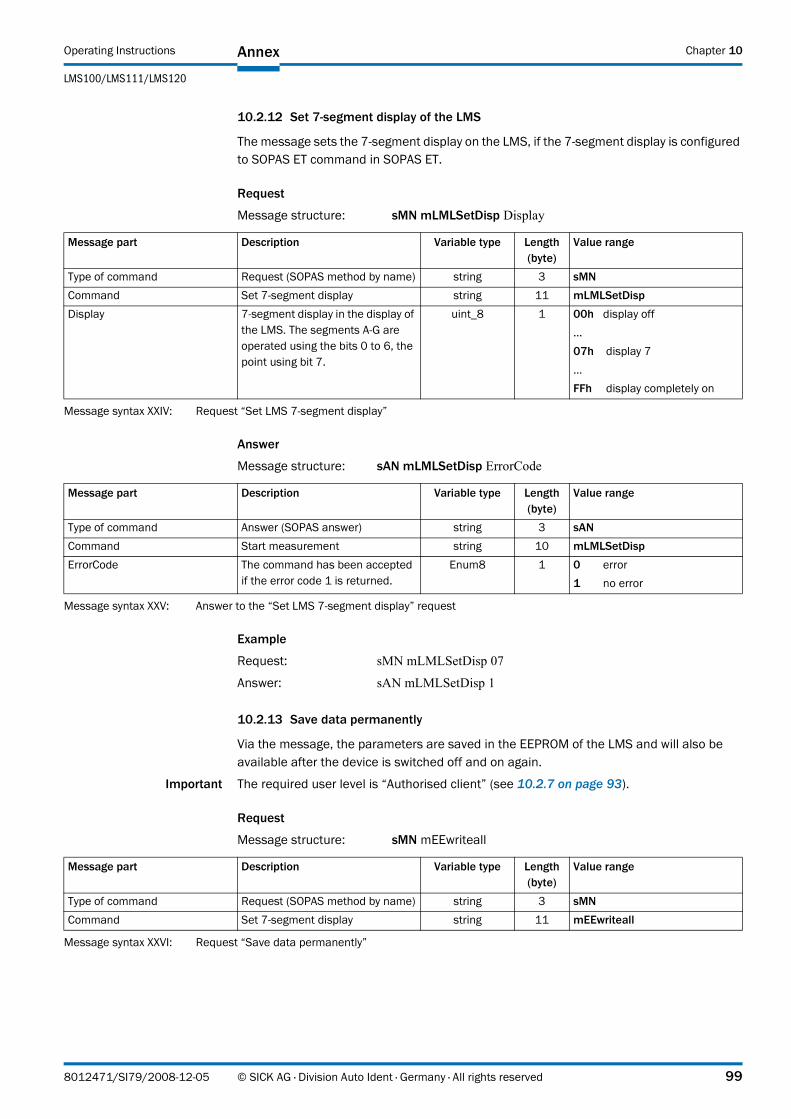
Operating Instructions
LMS100/LMS111/LMS120
Annex Chapter 10
10.2.12 Set 7-segment display of the LMS
The message sets the 7segment display on the LMS, if the 7segment display is configured to SOPAS ET command in SOPAS ET.
Request
Message structure: sMN mLMLSetDisp Display
Answer
Message structure: sAN mLMLSetDisp ErrorCode
Example
Request: sMN mLMLSetDisp 07
Answer: sAN mLMLSetDisp 1
10.2.13 Save data permanently
Via the message, the parameters are saved in the EEPROM of the LMS and will also be available after the device is switched off and on again.
Important The required user level is “Authorised client” (see 10.2.7 on page 93).
Request
Message structure: sMN mEEwriteall
Message part Description Variable type Length (byte)
Value range
Type of command Request (SOPAS method by name) string 3 sMNCommand Set 7-segment display string 11 mLMLSetDispDisplay 7-segment display in the display of
the LMS. The segments A-G are operated using the bits 0 to 6, the point using bit 7.
uint_8 1 00h display off…07h display 7…FFh display completely on
Message syntax XXIV: Request “Set LMS 7segment display”
Message part Description Variable type Length (byte)
Value range
Type of command Answer (SOPAS answer) string 3 sANCommand Start measurement string 10 mLMLSetDispErrorCode The command has been accepted
if the error code 1 is returned.Enum8 1 0 error
1 no error
Message syntax XXV: Answer to the “Set LMS 7segment display” request
Message part Description Variable type Length (byte)
Value range
Type of command Request (SOPAS method by name) string 3 sMNCommand Set 7-segment display string 11 mEEwriteall
Message syntax XXVI: Request “Save data permanently”
8012471/SI79/2008-12-05 © SICK AG · Division Auto Ident · Germany · All rights reserved 99
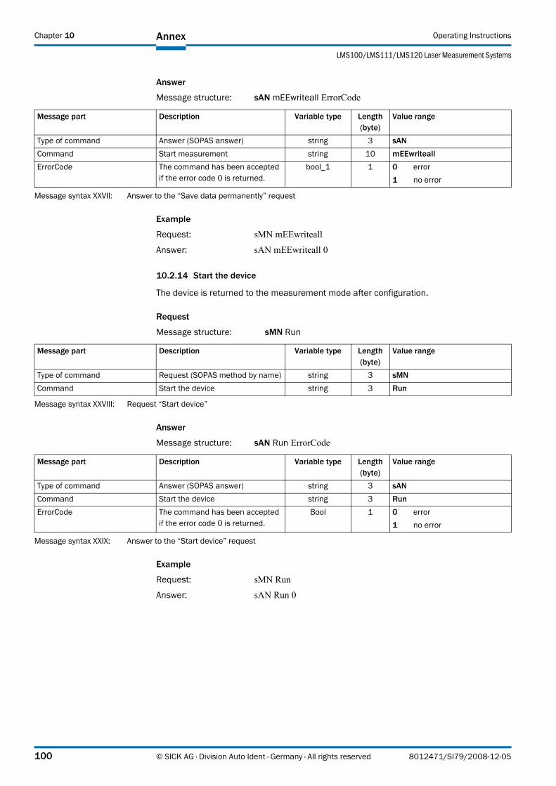
Annex Operating Instructions
LMS100/LMS111/LMS120 Laser Measurement Systems
Chapter 10
Answer
Message structure: sAN mEEwriteall ErrorCode
Example
Request: sMN mEEwriteall
Answer: sAN mEEwriteall 0
10.2.14 Start the device
The device is returned to the measurement mode after configuration.
Request
Message structure: sMN Run
Answer
Message structure: sAN Run ErrorCode
Example
Request: sMN Run
Answer: sAN Run 0
Message part Description Variable type Length (byte)
Value range
Type of command Answer (SOPAS answer) string 3 sANCommand Start measurement string 10 mEEwriteallErrorCode The command has been accepted
if the error code 0 is returned.bool_1 1 0 error
1 no error
Message syntax XXVII: Answer to the “Save data permanently” request
Message part Description Variable type Length (byte)
Value range
Type of command Request (SOPAS method by name) string 3 sMNCommand Start the device string 3 Run
Message syntax XXVIII: Request “Start device”
Message part Description Variable type Length (byte)
Value range
Type of command Answer (SOPAS answer) string 3 sANCommand Start the device string 3 RunErrorCode The command has been accepted
if the error code 0 is returned.Bool 1 0 error
1 no error
Message syntax XXIX: Answer to the “Start device” request
100 © SICK AG · Division Auto Ident · Germany · All rights reserved 8012471/SI79/2008-12-05
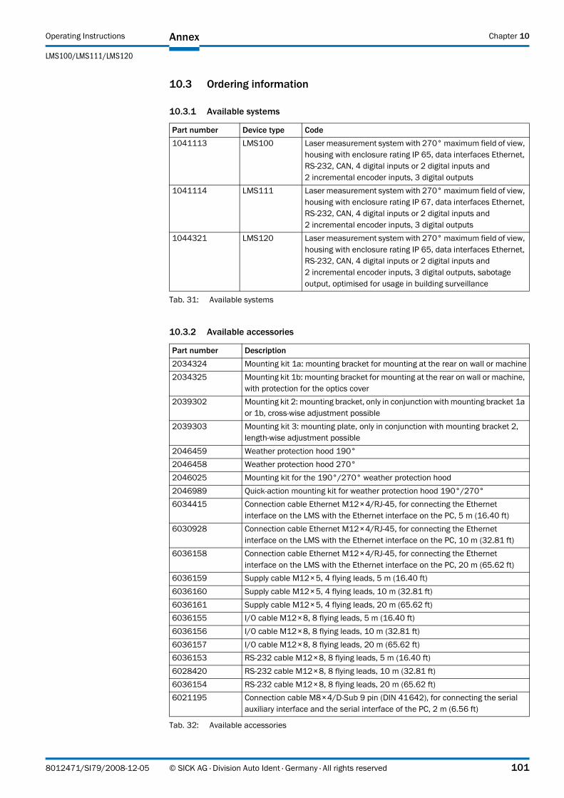
Operating Instructions
LMS100/LMS111/LMS120
Annex Chapter 10
10.3 Ordering information
10.3.1 Available systems
10.3.2 Available accessories
Part number Device type Code1041113 LMS100 Laser measurement system with 270° maximum field of view,
housing with enclosure rating IP 65, data interfaces Ethernet, RS232, CAN, 4 digital inputs or 2 digital inputs and 2 incremental encoder inputs, 3 digital outputs
1041114 LMS111 Laser measurement system with 270° maximum field of view, housing with enclosure rating IP 67, data interfaces Ethernet, RS232, CAN, 4 digital inputs or 2 digital inputs and 2 incremental encoder inputs, 3 digital outputs
1044321 LMS120 Laser measurement system with 270° maximum field of view, housing with enclosure rating IP 65, data interfaces Ethernet, RS232, CAN, 4 digital inputs or 2 digital inputs and 2 incremental encoder inputs, 3 digital outputs, sabotage output, optimised for usage in building surveillance
Tab. 31: Available systems
Part number Description2034324 Mounting kit 1a: mounting bracket for mounting at the rear on wall or machine2034325 Mounting kit 1b: mounting bracket for mounting at the rear on wall or machine,
with protection for the optics cover2039302 Mounting kit 2: mounting bracket, only in conjunction with mounting bracket 1a
or 1b, cross-wise adjustment possible2039303 Mounting kit 3: mounting plate, only in conjunction with mounting bracket 2,
length-wise adjustment possible2046459 Weather protection hood 190°2046458 Weather protection hood 270°2046025 Mounting kit for the 190°/270° weather protection hood2046989 Quick-action mounting kit for weather protection hood 190°/270°6034415 Connection cable Ethernet M12×4/RJ45, for connecting the Ethernet
interface on the LMS with the Ethernet interface on the PC, 5 m (16.40 ft)6030928 Connection cable Ethernet M12×4/RJ45, for connecting the Ethernet
interface on the LMS with the Ethernet interface on the PC, 10 m (32.81 ft)6036158 Connection cable Ethernet M12×4/RJ45, for connecting the Ethernet
interface on the LMS with the Ethernet interface on the PC, 20 m (65.62 ft)6036159 Supply cable M12×5, 4 flying leads, 5 m (16.40 ft)6036160 Supply cable M12×5, 4 flying leads, 10 m (32.81 ft)6036161 Supply cable M12×5, 4 flying leads, 20 m (65.62 ft)6036155 I/O cable M12×8, 8 flying leads, 5 m (16.40 ft)6036156 I/O cable M12×8, 8 flying leads, 10 m (32.81 ft)6036157 I/O cable M12×8, 8 flying leads, 20 m (65.62 ft)6036153 RS232 cable M12×8, 8 flying leads, 5 m (16.40 ft)6028420 RS232 cable M12×8, 8 flying leads, 10 m (32.81 ft)6036154 RS232 cable M12×8, 8 flying leads, 20 m (65.62 ft)6021195 Connection cable M8×4/DSub 9 pin (DIN 41642), for connecting the serial
auxiliary interface and the serial interface of the PC, 2 m (6.56 ft)
Tab. 32: Available accessories
8012471/SI79/2008-12-05 © SICK AG · Division Auto Ident · Germany · All rights reserved 101

Annex Operating Instructions
LMS100/LMS111/LMS120 Laser Measurement Systems
Chapter 10
2027649 Connection cable M8×4/DSub 9 pin (DIN 41642), for connecting the serial auxiliary interface and the serial interface of the PC, 10 m (32.81 ft)
2039808 CDROM “Manuals & Software Auto Ident”
Part number Description
Tab. 32: Available accessories
102 © SICK AG · Division Auto Ident · Germany · All rights reserved 8012471/SI79/2008-12-05
Operating Instructions
LMS100/LMS111/LMS120
Annex Chapter 10
10.4 Glossary
Download
Transmission of the parameter set that has been modified offline in the SOPAS ET configuration software from the PC to the LMS. SOPAS ET transmits either always a complete copy to the memory (RAM) of the LMS (menu COMMUNICATION, DOWNLOAD ALL PARAMETERS TO DEVICE) or only the parameter that has just been edited (menu COMMUNICATION,DOWNLOAD MODIFIED PARAMETERS TO DEVICE). With the menu LMS, PARAMETER, SAVE PERMANENT,the parameter set is saved permanently in the EEPROM of the LMS.
Field of view α
Angle that defines the limits to which the laser beam is deflected by the polygon mirror wheel. A v-shaped area is formed radially in the scan direction in front of the laser output aperture; this area must contain the objects to be measured.
Parameter set
Data set using which the functions implemented in the LMS are initialised and activated. Is transmitted from the LMS to SOPAS ET and in the reverse direction using UPLOAD or DOWNLOAD respectively.
Remission
Remission is the quality of reflection at a surface. The basis is the Kodak standard, known worldwide in, among other areas, photography.
Scan
A scan encompasses all measured values determined referred to the scanning angle and the speed of rotation of the mirror.
SOPAS ET
Configuration software, used for the offline configuration (adaptation to the read situation on-site) and the online operation of the LMS in dialog mode.
Upload
Transmission of the parameter set from the LMS to the PC into the SOPAS ET configuration software. The values for the parameters are displayed on the file cards of the configuration software. Prerequisite for the modification of the current parameter set.
8012471/SI79/2008-12-05 © SICK AG · Division Auto Ident · Germany · All rights reserved 103
Annex Operating Instructions
LMS100/LMS111/LMS120 Laser Measurement Systems
Chapter 10
10.5 EC Declaration of Conformity
Fig. 65 shows page 1 of the EC Declaration of Conformity (size reduced). The full EC Declaration of Conformity is available on request.
Fig. 65: Illustration containing the EC Declaration of Conformity
104 © SICK AG · Division Auto Ident · Germany · All rights reserved 8012471/SI79/2008-12-05

Operating Instructions
LMS100/LMS111/LMS120
Annex Chapter 10
8012471/SI79/2008-12-05 © SICK AG · Division Auto Ident · Germany · All rights reserved 105

8012
471/
SI79
/200
8-12
-05
∙ RV
<PM
6.5/
FM5.
5/PD
F>/X
X ∙ P
rinte
d in
Ger
man
y (2
008-
12) ∙
Sub
ject
to c
hang
e w
ithou
t not
ice
∙ The
spe
cifie
d pr
oduc
t fea
ture
s an
d te
chni
cal d
ata
do n
ot re
pres
ent a
ny g
uara
ntee
∙ 05
Pre
int6
2
AustraliaPhone +61 3 9497 4100 1800 33 48 02 – tollfreeE-Mail [email protected]Belgium/LuxembourgPhone +32 (0)2 466 55 66E-Mail [email protected]
BrasilPhone +55 11 3215-4900E-Mail [email protected]
Ceská RepublikaPhone +420 2 57 91 18 50E-Mail [email protected]
ChinaPhone +852-2763 6966E-Mail [email protected]
DanmarkPhone +45 45 82 64 00E-Mail [email protected]
DeutschlandPhone +49 211 5301-270E-Mail [email protected]
EspañaPhone +34 93 480 31 00E-Mail [email protected]
FrancePhone +33 1 64 62 35 00E-Mail [email protected]
Great BritainPhone +44 (0)1727 831121E-Mail [email protected]
IndiaPhone +91–22–4033 8333E-Mail [email protected]
IsraelPhone +972-4-999-0590E-Mail [email protected]
ItaliaPhone +39 02 27 43 41E-Mail [email protected]
JapanPhone +81 (0)3 3358 1341E-Mail [email protected]
NederlandsPhone +31 (0)30 229 25 44E-Mail [email protected]
Norge Phone +47 67 81 50 00E-Mail [email protected]
ÖsterreichPhone +43 (0)22 36 62 28 8-0E-Mail [email protected]
PolskaPhone +48 22 837 40 50E-Mail [email protected]
Republic of KoreaPhone +82-2 786 6321/4E-Mail [email protected]
Republika SlowenijaPhone +386 (0)1-47 69 990E-Mail [email protected]
RomâniaPhone +40 356 171 120 E-Mail [email protected]
RussiaPhone +7 495 775 05 34E-Mail [email protected]
SchweizPhone +41 41 619 29 39E-Mail [email protected]
SingaporePhone +65 6744 3732E-Mail [email protected]
SuomiPhone +358-9-25 15 800E-Mail [email protected]
SverigePhone +46 10 110 10 00E-Mail [email protected]
TaiwanPhone +886 2 2375-6288E-Mail [email protected]
TürkiyePhone +90 216 587 74 00E-Mail [email protected]
USA/Canada/MéxicoPhone +1(952) 941-6780 1 800-325-7425 – tollfreeE-Mail [email protected]
More representatives and agencies in all major industrial nations at www.sick.com
SICK AG | Waldkirch | Germany | www.sick.com