metasys integrator® carrier® application
TRANSCRIPT

Application NoteIssue Date April 15, 2003
© 2003 Johnson Controls, Inc. 1Code No. LIT-6295210 www.johnsoncontrols.com
Software Release 9.2
Metasys Integrator® Carrier® Application
lntroduction 3
• Application Details 3
• Component Requirements 6
• Vendor Contact Information 7
• Design Considerations 7
Cable Connections 8
• Cable Pinouts 8
• Connecting the Cable 8
Metasys Integrator Unit Setup 9
Point Mapping Tables 13
• 32MP Single Compressor Chiller and 19DK Centrifugal Chiller Points UsingDataPort Device 13
• 32MP Dual Compressor Chiller Points Using DataPort Device 14
• 32MP and 19DR Dual Compressor Chiller Points Using DataPort Device 15
• 19XL or 19EX Centrifugal Chiller Points Using DataPort Device 16
• 23XL Hermetic Screw Chiller Points Using DataPort Device 18
• 30GB and 30GN Reciprocating Chiller Phase 2 Using DataPort Device 20
• 30GN Reciprocating Chiller Points Using DataPort Device 21
• 30GT Reciprocating Chiller (PICI) Points Using DataPort Device 24
• 30HS Reciprocating Chiller Points Using DataPort Device 26

2 Metasys Integrator Carrier Application Application Note
• 17FA, 19FA, and 19XR Chiller (PICI) Points Using DataPort Device 26
• 19XR Hermetic Centrifugal Chiller (PICII) Points Using DataPort Device 29
• 48EJ, 48EK, 48EW, 48EY, 50EJ, 50EK, 50EW, and 50EY Single Package RooftopUnit Points Using DataPort Device 33
• Carrier 30HX and 30GX Screw Chiller Using DataPort Device Or DataLINK Modulewithout ComfortLink Controls 34
• Carrier 30HX/GX Screw Chiller Using DataLINK Module with ComfortLink Controls40
• Carrier 30RA AquaSnap Chiller Using DataLINK Module with ComfortLink Controls44
• 16JT Absorption Chiller Points Using DataPort Device 47
• 17FA, 19FA, 17EX, 19EX, 19XL, 19XR with PICI Controllers, and 23XL with PICIChiller Points Using DataLINK Module 49
• 19XR Hermetic Centrifugal Chiller (PICII) Points Using DataLINK Module 52
• 48EJ, 48EK, 48EW, 48EY, 50EJ, 50EK, 50EW, and 50EY Single Package RooftopUnit Points Using DataLINK Module 56
Metasys Network Setup 58
• Spare Sensors 58
• Mapping to a CS Object 58
Custom Integration 61

Metasys Integrator Carrier Application Application Note 3
lntroduction
This document explains the Metasys Integrator Carrier application.Use this document with the Metasys Integrator unit technical bulletins onthe Johnson Controls Product Information site(http://cgproducts.johnsoncontrols.com System Manuals > Integration >Metasys Integrator) which provide information on installing andcommissioning the Metasys Integrator unit. For information on the CarrierComfort Network (CCN) DataPort™ device and chillers, see Carrierdocumentation (obtainable from a Carrier representative).
Note: If you use a Universal Packaging Module (UPM) enclosure, youmust install the Metasys Integrator 300 Series in a two high enclosure(EN-EWC25-0) rather than a one high enclosure (EN-EWC13-0) asshown in the figures in this application note.
Metasys Integrator unit allows Carrier Product Integrated Controls (PIC)equipment to become an integral part of the Metasys and MetasysCompanion Networks. Once a CCN DataPort device or DataLINK™module is connected to a Metasys or Companion Network via the MetasysIntegrator unit, its data is available to the full complement of MetasysBuilding Automation System (BAS) features, including Change-of-State(COS) monitoring, trend, and totalization.
The DataPort device is an interface that allows information from the CCNto be transmitted to non Carrier devices. Since the DataPort device is aread-only device (that is, the BAS reads only status and data from themechanical equipment), it does not transmit data or commands from theMetasys System to the mechanical equipment. Single and dual compressorchillers connect to a 32MP Gateway (an input/output module), whichconnects to the DataPort device. All other Carrier mechanical equipmentsupported by Metasys Integrator applications connect directly to theDataPort device.
The CCN DataLINK module is an interface device that can read and writevalues to devices connected to a CCN communication bus. The DataLINKmodule acts as a data concentrator for the mechanical equipment and as aninterface to other equipment. The DataLINK module converts the statusinformation requests from each chiller into American Standard Code forInformation Interchange (ASCII) for display.
Each Metasys Integrator vendor port can connect to one DataPort deviceor DataLINK module. Each DataPort device or DataLINK module canconnect to 15 devices.Figure 1 shows Carrier and Metasys system integration. Figure 2 showsCarrier and Metasys Companion system integration.
ApplicationDetails

4 Metasys Integrator Carrier Application Application Note
N2 Bus
RS-232
N1 LAN
MetasysIntegrator
19XLChiller
Controller
32MPChiller
Controller
32MPChiller
Controller
intcarr1
32MPGateway
32MPGateway
CCNDataPort
30 SeriesChiller
Controller
u m p
Standard NCU(Network Control
Unit)
UNT(Unitary
Controller)
Note: If you use a UPM enclosure, you must install the Metasys Integrator 300 Series in atwo high enclosure (EN-EWC25-0) rather than a one high enclosure (EN-EWC13-0) asshown in the figures in this application note.
Figure 1: Carrier CCN DataPort Device and Metasys System Integration

Metasys Integrator Carrier Application Application Note 5
N2 Bus
UNT
MetasysIntegrator
carrcomp
CCNDataPortRS-232
19XLChiller
Controller
32MPChiller
Controller
32MPChiller
Controller
32MPGateway
32MPGateway
30 SeriesChiller
Controller
Panel Unit Workstation
Note: A PC version and converter may be substituted for the Panel unit.
Note: If you use a UPM enclosure, you must install the Metasys Integrator 300 Series in atwo high enclosure (EN-EWC25-0) rather than a one high enclosure (EN-EWC13-0) asshown in the figures in this application note.
Figure 2: Carrier CCN DataPort Device and Metasys Companion SystemIntegration

6 Metasys Integrator Carrier Application Application Note
To integrate the DataPort device or DataLINK module, you need thefollowing:
• properly installed Carrier CCN DataPort device, CCN DataLINKmodule, 32MP Gateway modules, and chillers
• RS-232 cable (for connecting the DataPort device to theMetasys Integrator unit)
• Metasys Integrator unit
• N2 Bus (for connecting the Metasys Integrator unit to the Metasys orCompanion Network)
• portable PC for downloading vendor communication tables(.VCT files) and network setup information into theMetasys Integrator unit, and for running diagnostics
• cable for connecting portable PC to the Metasys Integrator unit
• the correct vendor communication table (.VCT file) to download intothe Metasys Integrator unit (supplied on CD-ROM)
This document describes the RS-232 cable and the vendor communicationtables. Carrier documentation describes their equipment. The remainingcomponents are described in the Metasys Integrator unit technicalbulletins on the Johnson Controls Product Information site(http://cgproducts.johnsoncontrols.com System Manuals > Integration >Metasys Integrator).
To integrate Carrier equipment into the Metasys Network, you need:
• Metasys Operator Workstation (OWS) software Release 6.0 or later
• Metasys Integrator software/firmware Release 9.0 or later
To integrate Carrier equipment into the Metasys Companion Network, youneed:
• Metasys Companion Release 5.0 or later
• Metasys Integrator software/firmware Release 9.0 or later
ComponentRequirements
Metasys NetworkReleaseRequirements
MetasysCompanionReleaseRequirements

Metasys Integrator Carrier Application Application Note 7
Integration between the Metasys Integrator unit and Carrier has beentested with the equipment in Table 1.
Table 1: Equipment and Part NumbersCarrier Equipment Part NumberCCN DataPort Device CEPL130363-01CCN DataLINK Module* CEFA121549-0132MP Gateway CEFA121301-02 and CEFA121301-05PIC ---PICII ---* The DataLINK module is sometimes referred to as a DataPort II device.
Changes to the DataPort device or DataLINK module, Gateway, PIC,chillers, or integration of Carrier products not discussed in this document,require additional software development and testing by Johnson ControlsSystems Products. For information on integrating other products, refer tothe Custom Integration section in this document.
Note: 30GT units are no longer shipped with PIC and are availablefor retrofit only.
For technical information about Carrier equipment, contact your localCarrier equipment distributor.
When integrating Carrier equipment, keep the following considerations inmind:• Make sure all Carrier equipment is set up and running properlybefore attempting to integrate with Metasys or Metasys CompanionNetwork. (The Carrier representative is responsible for operation ofDataPort device, Gateway, and chillers.)
• The DataPort device should be set up using full 8-character names forpoint descriptions. Names less than eight characters should beextended with spaces.
• Make sure the DataPort device or DataLINK module baud rate is set to9600. (The Carrier representative is responsible for setting theDataPort device baud rate.)
• RS-232 cable distance between the Metasys Integrator unit and theDataPort device can be a maximum of 50 feet.
VendorComponentRequirements
Vendor ContactInformation
DesignConsiderations

8 Metasys Integrator Carrier Application Application Note
Cable Connections
Use the following cable pinouts for the RS-232 connection between theMetasys Integrator unit and the Carrier CCN DataPort device andDataLINK module:
DB-9 Female
Signal Pin
RDTDGND
235
DB-25 Male
SignalPin
TDRDGND
237
RS-232
Vendor Port A or Bon Metasys Integrator
COMM2on the DataPort
or DataLINK
(50 ft maximum)intcarr2
Figure 3: Cable Pinouts
Connect the female end of the RS-232 cable to either Vendor Port A orVendor Port B on the Metasys Integrator unit. Connect the male end toPort COMM2 on the DataPort device or DataLINK module.
MetasysIntegrator
DataPortor DataLINK
COMM2Vendor Port
A or BRS-232 Cable
intcarr3
Figure 4: Port-to-Port Connection
Cable Pinouts
Connecting theCable

Metasys Integrator Carrier Application Application Note 9
Metasys Integrator Unit Setup
To set up the Metasys Integrator unit, use a portable PC connected to theMetasys Integrator Terminal Port. Metasys Integrator unit setup involves:
• downloading the correct vendor communication table (.VCT file)
• setting up the port
• setting up the network addressing
Table 2 provides information specific to the Carrier application. Fordetailed procedures, see the Metasys Integrator unit technical bulletins onthe Johnson Controls Product Information site(http://cgproducts.johnsoncontrols.com System Manuals > Integration >Metasys Integrator).
Table 2: Metasys Integrator Unit Setup for 32MP DataPort DeviceVendor Communication Table (.VCT File)Single Compressor Chiller (with Rev. 01or 02 of the 32MP Gateway)
CA_SIGL.VCT
Single compressor Chiller (with Rev. 03,04, or 05 of the 32 MP Gateway)
CA_SIGL2.VCT
Dual Compressor ChillerDual Compressor Chiller (19DR)
CA_DUAL.VCTCA_19DR.VCT
19DK Centrifugal Chiller CA_19DK.VCT19XL Centrifugal Chiller19EX Centrifugal Chiller
CA_19XL.VCT
23XL Hermetic Screw Chiller CA_23XL.VCT30GB Reciprocating Chiller CA_30GB.VCT30GN Reciprocating Chiller CA_30GN.VCT30GT Reciprocating Chiller CA_30GT. VCT30HS Reciprocating Chiller CA_30HS. VCT17FA Centrifugal Chiller-Open Drive19FA Centrifugal Chiller-Hermetic19XR Centrifugal Chiller-Hermetic,Small Tonnage
CA_17FA. VCT
16JT Absorption Chiller CDP16JT.VCT19XR Centrifugal Chiller Hermetic withPICII Controller, Small Tonnage (Version 01)
CDP19XR2.VCT
30HX Water-Cooled Screw Chiller withoutComfortLink Controls30GX Air-Cooled Screw Chiller withoutComfortLink Controls
CA_30HX.VCT
Continued on next page . . .

10 Metasys Integrator Carrier Application Application Note
Vendor Communication Table (.VCT File) (Cont.)48EJ Single Package Rooftop Unit48EK Single Package Rooftop Unit48EW Single Package Rooftop Unit48EY Single Package Rooftop Unit50EJ Single Package Rooftop Unit50EK Single Package Rooftop Unit50EW Single Package Rooftop Unit50EY Single Package Rooftop Unit
CA_EXRT. VCT
48EJ Single Package Rooftop Unit48EK Single Package Rooftop Unit48EW Single Package Rooftop Unit48EY Single Package Rooftop Unit50EJ Single Package Rooftop Unit50EK Single Package Rooftop Unit50EW Single Package Rooftop Unit50EY Single Package Rooftop Unit
CA_EXRT. VCT
Port SetupBaud Rate 9600Word Length 8Stop Bits 1Parity NoneInterface RS-232
Network SetupVendor Address A through OTimeout Value (all but 30HX)Timeout Value for 30HX
8000 ms16000 ms
Poll Delay 550 msContinued on next page . . .
Metasys Integrator Carrier Application Application Note 11
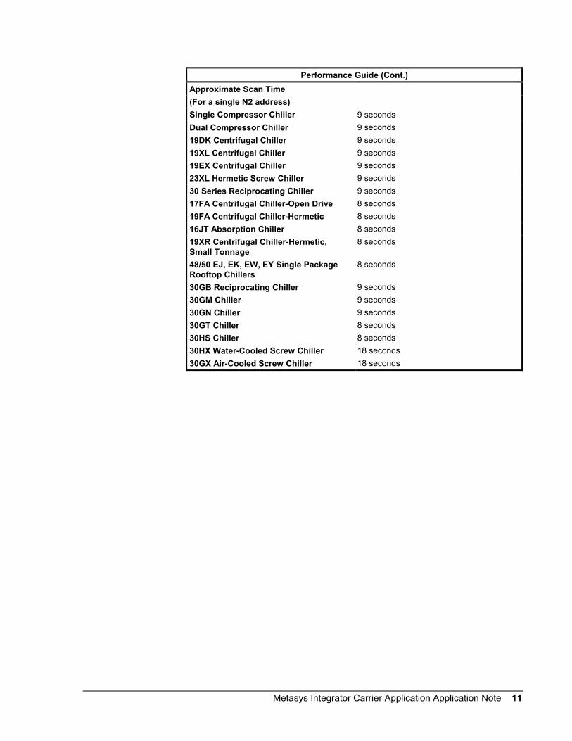
Performance Guide (Cont.)Approximate Scan Time(For a single N2 address)Single Compressor Chiller 9 secondsDual Compressor Chiller 9 seconds19DK Centrifugal Chiller 9 seconds19XL Centrifugal Chiller 9 seconds19EX Centrifugal Chiller 9 seconds23XL Hermetic Screw Chiller 9 seconds30 Series Reciprocating Chiller 9 seconds17FA Centrifugal Chiller-Open Drive 8 seconds19FA Centrifugal Chiller-Hermetic 8 seconds16JT Absorption Chiller 8 seconds19XR Centrifugal Chiller-Hermetic,Small Tonnage
8 seconds
48/50 EJ, EK, EW, EY Single PackageRooftop Chillers
8 seconds
30GB Reciprocating Chiller 9 seconds30GM Chiller 9 seconds30GN Chiller 9 seconds30GT Chiller 8 seconds30HS Chiller 8 seconds30HX Water-Cooled Screw Chiller 18 seconds30GX Air-Cooled Screw Chiller 18 seconds

12 Metasys Integrator Carrier Application Application Note
Table 3: Metasys Integrator Unit Setup for DataLINK ModuleVendor Communication Table (.VCT File)17FA, 19FA Chiller17EX, 19EX Chiller19XL Chiller19XR Hermetic Centrifugal Chiller withPICI Controller23XL Chiller
CA_DL_19.VCT
19XR Hermetic Centrifugal Chiller withPICII Controller (Version 01)
CDL19XR2.VCT
48EJ Single Package Rooftop Unit48EK Single Package Rooftop Unit48EW Single Package Rooftop Unit48EY Single Package Rooftop Unit50EJ Single Package Rooftop Unit50EK Single Package Rooftop Unit50EW Single Package Rooftop Unit50EY Single Package Rooftop Unit
CDL_RT.VCT
30HX Water-Cooled Screw Chiller withoutComfortLink Controls30GX Air-Cooled Screw Chiller withoutComfortLink Controls
CDL30HX.VCT
30HX Water-Cooled Screw Chiller withComfortLink Controls30GX Air-Cooled Screw Chiller withComfortLink Controls
C30GXDLC.VCT
30RA AquaSnap™ Chiller withComfortLink Controls
C30RADL.VCT
Network SetupVendor Address Device Number (1 to 15)Timeout Value 5000 msPoll Delay 550 ms
Performance GuideApproximate Scan Time(For a Single MIG Device)17, 19, 23 Series Chillers 8 seconds

Metasys Integrator Carrier Application Application Note 13
Point Mapping Tables
The following tables show the points available for mapping in single anddual compressor chillers.
To get the hardware reference for mapping points to a CS object (via thesoftware model), combine the Network Point Type (NPT) and NetworkPoint Address (NPA). For example, the hardware reference for theDemand Limit point is AI2.
The Analog Data Integer (ADI) points (internal parameters) cannot bemapped to standard objects. To monitor the ADIs, map them to ControlSystem (CS) object Analog Data (AD) attributes (which can then bemapped to standard AD objects).
Table 4: 32MP (Version 02) Single Compressor Chiller and 19DKCentrifugal Chiller Point Mapping Using DataPort DeviceNPT1 NPA2 Unit DescriptionAI 1 DegF Leaving Chill Water SetpointAI 2 % Demand LimitAI 3 DegF Leaving Chill Water TemperatureAI 4 DegF Evaporator Refrigerant Trip PointAI 5 DegF Evaporator Refrigerant TemperatureAI 6 DegF Condenser Refrigerant TemperatureAI 7 % Compressor Motor CurrentAI 8 % Compressor Motor LoadAI 9 DegF Motor Winding TemperatureAI 10 DegF Motor Discharge TemperatureAI 11 DegF Motor Thrust Bearing TemperatureAI 12 DegF Spare Sensor 1AI 13 DegF Spare Sensor 2AI 14 DegF Spare Sensor 3AI 15 DegF Spare Sensor 4BI 1 Chiller Start/Stop Status 0-Stop, 1-StartBI 2 Remote Contact Status 0-Open, 1-ClosedBI 3 Local/Remote Set Remote 0-Local, 1-RemoteADI 1 code Chiller Status CodeADI 2 hour Compressor On TimeADI 3 code Shutdown Code 1ADI 4 code Shutdown Code 2ADI 5 code Shutdown Code 3ADI 6 code Shutdown Code 4ADI 7 code Shutdown Code 5ADI 8 VAC Line Voltage3 or Control Voltage4
ADI 9 # Number of Starts in 12 Hours1 Network Point Type2 Network Point Address3 32MP Single Compressor Chiller Value4 19DK Centrifugal Chiller Value
32MP SingleCompressorChiller and19DKCentrifugalChiller PointsUsing DataPortDevice

14 Metasys Integrator Carrier Application Application Note
To get the hardware reference for mapping points to a CS object (via thesoftware model), combine the Network Point Type (NPT) and NetworkPoint Address (NPA). For example, the hardware reference for theDemand Limit point is AI2.
The ADI points (internal parameters) cannot be mapped to standardobjects. To monitor the ADIs, map them to CS object AD attributes(which can then be mapped to standard AD objects).
Table 5: 32MP (Version 03) Dual Compressor Chiller Points UsingDataPort DeviceNPT1 NPT2 Unit DescriptionAI 1 DegF Leaving Chill Water SetpointAI 2 % Demand LimitAI 3 DegF Leaving Chill Water TemperatureAI 4 DegF Evaporator Refrigerant Trip PointAI 5 DegF Evaporator Refrigerant TemperatureAI 6 DegF Condenser Refrigerant TemperatureAI 7 % Compressor A Motor CurrentAI 8 % Compressor B Motor CurrentAI 9 % Compressor A Motor LoadAI 10 % Compressor B Motor LoadAI 11 DegF Motor A Winding TemperatureAI 12 DegF Motor B Winding TemperatureAI 13 DegF Motor A Discharge TemperatureAI 14 DegF Motor B Discharge TemperatureAI 15 DegF Motor A Thrust Bearing TemperatureAI 16 DegF Motor B Thrust Bearing TemperatureAI 17 DegF Spare Sensor 1AI 18 DegF Spare Sensor 2AI 19 DegF Spare Sensor 3AI 20 DegF Spare Sensor 4BI 1 Chiller Start/Stop Status 0-Stop 1-StartBI 2 Remote Contact Status 0-Open 1-ClosedBI 3 Compressor B is Lead 0-B=Lag 1-B=LeadBI 4 Local/Remote Set Remote 0-Local 1-RemoteBI 5 Lag Disable Switch Set 0-Lag_En 1-Lag_DisADI 1 code Lead Compressor Status CodeADI 2 code Lag Compressor Status CodeADI 3 code Compressor On TimeADI 4 code Shutdown Code 1ADI 5 code Shutdown Code 2ADI 6 code Shutdown Code 3ADI 7 code Shutdown Code 4ADI 8 code Shutdown Code 5ADI 9 VAC Line VoltageADI 10 # Number of Starts in 12 Hours1 Network Point Type2 Network Point Address
32MP DualCompressorChiller PointsUsing DataPortDevice

Metasys Integrator Carrier Application Application Note 15
To get the hardware reference for mapping points to a CS object (via thesoftware model), combine the Network Point Type (NPT) and NetworkPoint Address (NPA). For example, the hardware reference for theDemand Limit point is AI2.
The ADI points (internal parameters) cannot be mapped to standardobjects. To monitor the ADIs, map them to CS object AD attributes(which can then be mapped to standard AD objects).
Table 6: 32MP (Version 04, 05) and 19DR Dual Compressor Chiller PointsUsing DataPort DeviceNPT1 NPT2 Units DescriptionAI 1 DegF Leaving Chill Water SetpointAI 2 % Demand LimitAI 3 DegF Leaving Chill Water TemperatureAI 4 DegF Evaporator Refrigerant Trip PointAI 5 DegF Evaporator Refrigerant TemperatureAI 6 DegF Condenser Refrigerant TemperatureAI 7 % Compressor A Motor CurrentAI 8 % Compressor B Motor CurrentAI 9 % Compressor A Motor LoadAI 10 DegF Compressor B Motor LoadAI 11 DegF Motor A Winding TemperatureAI 12 DegF Motor B Winding TemperatureAI 13 DegF Compressor A Discharge TemperatureAI 14 DegF Compressor B Discharge TemperatureAI 15 DegF Compressor A Thrust Bearing TemperatureAI 16 DegF Compressor B Thrust Bearing TemperatureAI 17 DegF Spare Sensor 1AI 18 DegF Spare Sensor 2AI 19 DegF Spare Sensor 3AI 20 DegF Spare Sensor 4BI 1 Chiller Start/Stop Status 0-Stop 1-StartBI 2 Remote Contact Input 0-Local 1-RemoteBI 3 Compressor B Is Lead 0-B=Lag 1-B=LeadBI 4 Remote Mode Enabled 0-False 1-TrueBI 5 Lag Disable Switch Set 0-Lag_En 1-Lag_DisADI 1 code Lead Compressor Status CodeADI 2 code Lag Compressor Status CodeADI 3 hour Compressor On TimeADI 4 code Shutdown Code 1ADI 5 code Shutdown Code 2ADI 6 code Shutdown Code 3ADI 7 code Shutdown Code 4ADI 8 code Shutdown Code 5ADI 9 VAC Control VoltageADI 10 # Number of Starts in 6 Hours1 Network Point Type2 Network Point Address
32MP and 19DRDualCompressorChiller PointsUsing DataPortDevice

16 Metasys Integrator Carrier Application Application Note
To get the hardware reference for mapping points to a CS object (via thesoftware model), combine the Network Point Type (NPT) and NetworkPoint Address (NPA). For example, the hardware reference for theEntering Chill Water point is AI3.
Table 7: 19XL or 19EX Centrifugal Chiller Points Using DataPort DeviceNPT1 NPT2 Units DescriptionAI 1 DegF Water/Brine SetpointAI 2 DegF Water/Brine Control PointAI 3 DegF Entering Chill WaterAI 4 DegF Leaving Chill WaterAI 5 DegF Entering Condenser WaterAI 6 DegF Leaving Condenser WaterAI 7 DegF Evaporator Refrigerant TemperatureAI 8 psi Evaporator PressureAI 9 DegF Condenser Refrigerant TemperatureAI 10 psi Condenser PressureAI 11 DegF Discharge TemperatureAI 12 DegF Bearing TemperatureAI 13 DegF Motor Winding TemperatureAI 14 DegF Oil Sump TemperatureAI 15 psi Oil Pressure TransducerAI 16 psi Oil Differential PressureAI 17 % Base Demand LimitAI 18 % Active Demand LimitAI 19 % Line Voltage PercentAI 20 Volt Line Voltage ActualAI 21 % Compressor Motor LoadAI 22 % Compressor Motor CurrentAI 23 Amps Compressor Motor AmperesAI 24 % Target Vane PositionAI 25 % Actual Vane PositionAI 26 # Total Compressor StartsAI 27 # Starts in 12 HoursAI 28 Hour Compressor OntimeAI 29 Hour Service OntimeAI 30 KW Compressor Motor kWAI 31 mA Demand Limit 4-20 mAAI 32 mA Temperature Reset 4-20 mAAI 33 DegF Common CHWS SensorAI 34 DegF Common CHWR SensorBI 1 Occupied 0-No, 1-YesBI 2 Alarm State 0-Ok, 1-AlarmBI 3 Chiller Start/Stop 0-Stop, 1-StartBI 4 Hot Gas Bypass Relay 0-No, 1-YesBI 5 Chilled Water Pump 0-No, 1-Yes1 Network Point Type2 Network Point AddressContinued on next page . . .
19XL or 19EXCentrifugalChiller PointsUsing DataPortDevice

Metasys Integrator Carrier Application Application Note 17
NPT1
(Cont.)NPT2 Units Description
BI 6 Chilled Water Flow 0-No, 1-YesBI 7 Condenser Water Pump 0-No, 1-YesBI 8 Condenser Water Flow 0-No, 1-YesBI 9 Compressor Start Relay 0-No, 1-YesBI 10 Compressor Start Contact 0-No, 1-YesBI 11 Compressor Run Contact 0-No, 1-YesBI 12 Starter Fault Contact 0-No, 1-YesBI 13 Pressure Trip Contact 0-No, 1-YesBI 14 Single Cycle Dropout 0-No, 1-YesBI 15 Oil Pump Relay 0-No, 1-YesBI 16 Oil Heater Relay 0-No, 1-YesBI 17 Motor Cooling Relay 0-No, 1-YesBI 18 Tower Fan Relay 0-No, 1-YesBI 19 Compressor Shunt Trip Relay 0-No, 1-YesBI 20 Alarm Relay 0-No, 1-YesBI 21 Remote Contacts Input 0-No, 1-YesBI 26 Unloader 1 0-No, 1-YesBI 27 Unloader 2 0-No, 1-YesBI 28 Outdoor Fan 1 0-No, 1-YesBI 29 Outdoor Fan 2 0-No, 1-YesBI 30 Y1 – Call for Cool 1 0-No, 1-YesBI 31 Y2 – Call for Cool 2 0-No, 1-YesBI 32 W1 – Call for Heat 1 0-No, 1-YesBI 33 W2 – Call for Heat 2 0-No, 1-YesBI 34 G – Call for Fan 0-No, 1-YesBI 35 Stage 1 Modulated Power Exhaust 0-No, 1-YesBI 36 Stage 2 Modulated Power Exhaust 0-No, 1-YesBI 37 Stage 3 Modulated Power Exhaust 0-No, 1-YesBI 38 Stage 4 Modulated Power Exhaust 0-No, 1-Yes1 Network Point Type2 Network Point Address

18 Metasys Integrator Carrier Application Application Note
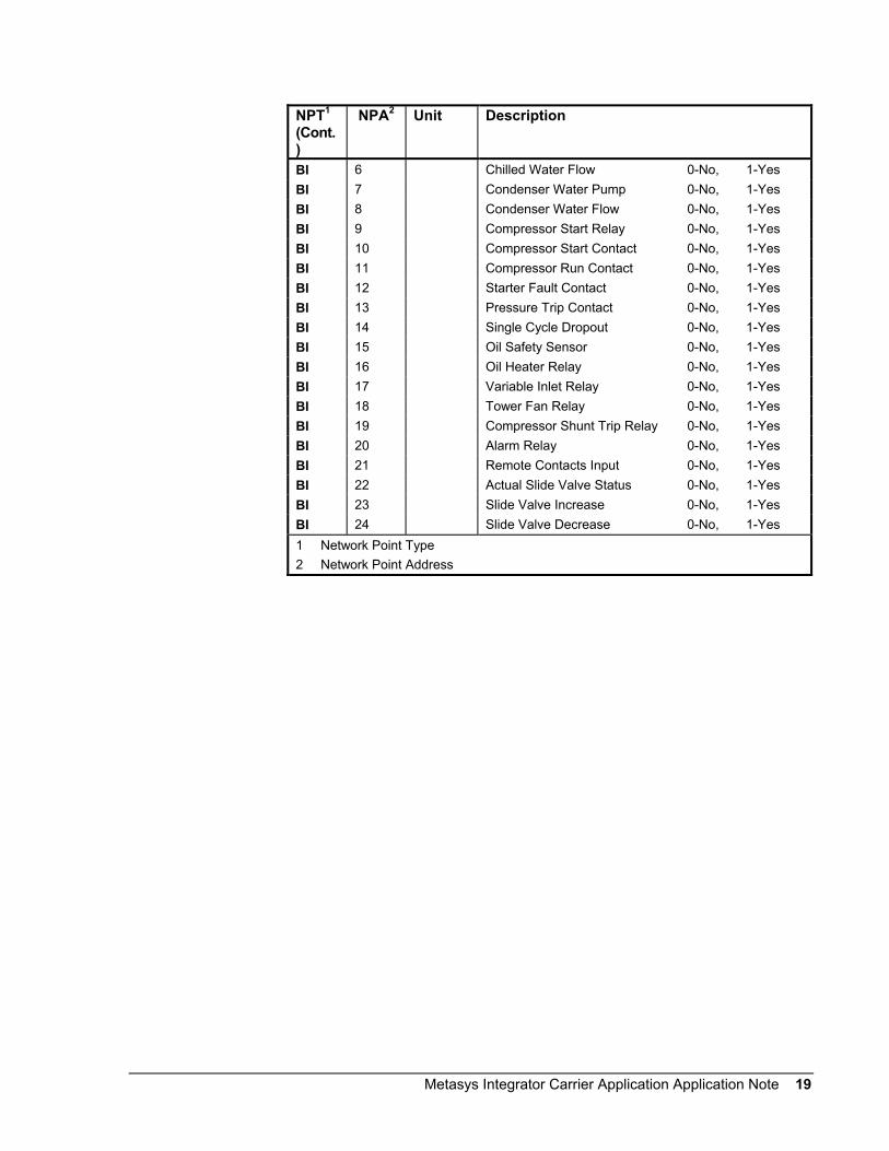
To get the hardware reference for mapping points to a CS object (via thesoftware model), combine the Network Point Type (NPT) and NetworkPoint Address (NPA). For example, the hardware reference for theEntering Chill Water point is AI3.
Table 8: 23XL Hermetic Screw Chiller Points Using DataPort DeviceNPT1 NPA2 Unit DescriptionAI 1 DegF Water/Brine SetpointAI 2 DegF Water/Brine Control PointAI 3 DegF Entering Chill WaterAI 4 DegF Leaving Chill WaterAI 5 DegF Entering Condenser WaterAI 6 DegF Leaving Condenser WaterAI 7 DegF Evaporator Refrigerant TemperatureAI 8 psi Evaporator PressureAI 9 DegF Condenser Refrigerant TemperatureAI 10 Psi Condenser PressureAI 11 DegF Discharge TemperatureAI 12 DegF Rotor Inlet TemperatureAI 13 DegF Motor Winding TemperatureAI 14 DegF Oil Sump TemperatureAI 15 Psi Oil Pressure TransducerAI 16 psi Oil Differential PressureAI 17 % Base Demand LimitAI 18 % Active Demand LimitAI 19 % Line Voltage PercentAI 20 Volt Line Voltage ActualAI 21 % Compressor Motor LoadAI 22 % Compressor Motor CurrentAI 23 Amperes Compressor Motor AmperesAI 24 DegF Common CHWS SensorAI 25 DegF Common CHWR SensorAI 26 # Total Compressor StartsAI 27 # Starts in 12 HoursAI 28 Hour Compressor OntimeAI 29 Hour Service OntimeAI 30 kW Compressor Motor kWAI 31 mA Demand Limit 4-20 mAAI 32 mA Temperature Reset 4-20 mAAI 33 # Manual Slide Valve CountBI 1 Occupied 0-No, 1-YesBI 2 Alarm State 0-Ok, 1-AlarmBI 3 Chiller Start/Stop 0-Stop, 1-StartBI 4 Hot Gas Bypass Relay 0-No, 1-YesBI 5 Chilled Water Pump 0-No, 1-Yes1 Network Point Type2 Network Point AddressContinued on next page . . .
23XL HermeticScrew ChillerPoints UsingDataPortDevice
Metasys Integrator Carrier Application Application Note 19
NPT1
(Cont.)
NPA2 Unit Description
BI 6 Chilled Water Flow 0-No, 1-YesBI 7 Condenser Water Pump 0-No, 1-YesBI 8 Condenser Water Flow 0-No, 1-YesBI 9 Compressor Start Relay 0-No, 1-YesBI 10 Compressor Start Contact 0-No, 1-YesBI 11 Compressor Run Contact 0-No, 1-YesBI 12 Starter Fault Contact 0-No, 1-YesBI 13 Pressure Trip Contact 0-No, 1-YesBI 14 Single Cycle Dropout 0-No, 1-YesBI 15 Oil Safety Sensor 0-No, 1-YesBI 16 Oil Heater Relay 0-No, 1-YesBI 17 Variable Inlet Relay 0-No, 1-YesBI 18 Tower Fan Relay 0-No, 1-YesBI 19 Compressor Shunt Trip Relay 0-No, 1-YesBI 20 Alarm Relay 0-No, 1-YesBI 21 Remote Contacts Input 0-No, 1-YesBI 22 Actual Slide Valve Status 0-No, 1-YesBI 23 Slide Valve Increase 0-No, 1-YesBI 24 Slide Valve Decrease 0-No, 1-Yes1 Network Point Type2 Network Point Address

20 Metasys Integrator Carrier Application Application Note
To get the hardware reference for mapping points to a CS object (via thesoftware model), combine the Network Point Type (NPT) and NetworkPoint Address (NPA). For example, the hardware reference for theMotormaster Speed point is AI2.
Table 9: 30GB Reciprocating Chiller Points and 30GN Phase 2 UsingDataPort DeviceNPT1 NPA2 Unit DescriptionAI 1 % EXV PositionAI 2 % Motormaster SpeedAI 3 % Water Valve PositionBI 1 Alarm Relay 0-Ok, 1-AlarmBI 2 Heat/Cool Switch 0-No, 1-YesBI 3 Heat/Cool Select 0-No, 1-YesBI 4 Cooler Pump Relay 0-No, 1-YesBI 5 Condenser Pump Relay 0-No, 1-YesBI 6 Emergency Stop/Enable 0-No, 1-YesBI 7 Local/Stop/CNN Switch 0-No, 1-YesBI 8 Stop/Start From CNN 0-No, 1-YesBI 9 Demand Switch 1 0-No, 1-YesBI 10 Demand Switch 2 0-No, 1-YesBI 11 Dual Setpoint Switch 0-No, 1-YesBI 12 Clock Status Switch 0-No, 1-Yes
Circuit ABI 13 Oil Pressure Switch 0-Open, 1-CloseBI 14 Fan 1 Relay 0-No, 1-YesBI 15 Fan 2 Relay 0-No, 1-YesBI 16 Hot Gas Bypass Valve 0-No, 1-YesBI 17 Liquid Line Solenoid 0-No, 1-YesBI 18 Compressor A1 Output 0-No, 1-YesBI 19 Compressor A2 Output 0-No, 1-YesBI 20 Compressor A3 Output 0-No, 1-YesBI 21 Compressor A4 Output 0-No, 1-YesBI 22 Unloader A1 0-No, 1-YesBI 23 Unloader A2 0-No, 1-Yes
Circuit BBI 24 Oil Pressure Switch 0-Open, 1-CloseBI 25 Fan 1 Relay 0-No, 1-YesBI 26 Fan 2 Relay 0-No, 1-YesBI 27 Hot Gas Bypass Valve 0-No, 1-YesBI 28 Liquid Line Solenoid 0-No, 1-YesBI 29 Compressor B1 Output 0-No, 1-YesBI 30 Compressor B2 Output 0-No, 1-YesBI 31 Compressor B3 Output 0-No, 1-YesBI 32 Compressor B4 Output 0-No, 1-YesBI 33 Unloader B1 0-No, 1-YesBI 34 Unloader B2 0-No, 1-Yes1 Network Point Type2 Network Point Address
30GB and30GNReciprocatingChiller Phase 2Using DataPortDevice

Metasys Integrator Carrier Application Application Note 21
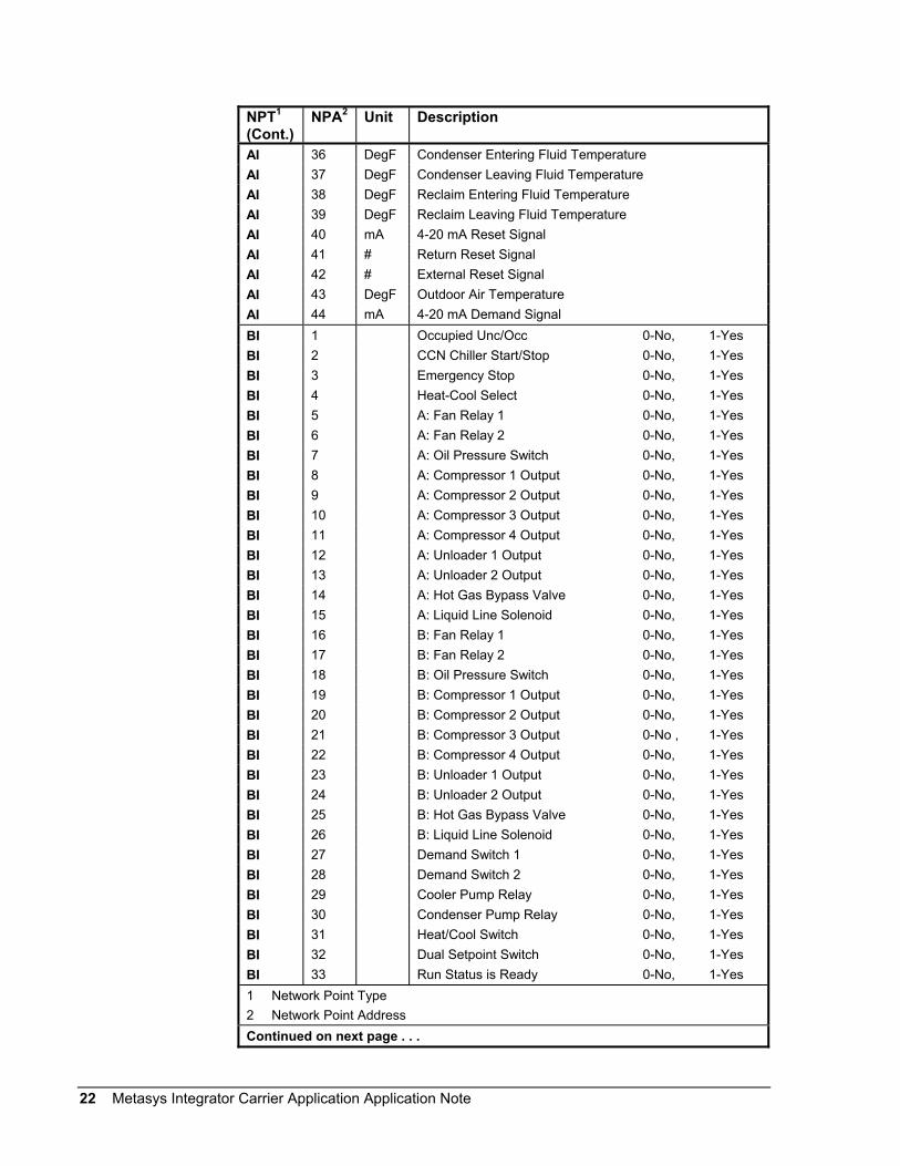
To get the hardware reference for mapping points to a CS object (via thesoftware model), combine the Network Point Type (NPT) and NetworkPoint Address (NPA). For example, the hardware reference for the PercentTotal Capacity point is AI2.
Table 10: 30GN Reciprocating Chiller Point Mapping Phase 3 UsingDataPort DeviceNPT1 NPA2 Unit DescriptionAI 1 % Active Demand LimitAI 2 % Percent Total CapacityAI 3 DegF Water/Brine SetpointAI 4 DegF Control PointAI 5 DegF Entering Chilled Water TemperatureAI 6 DegF Leaving Chilled Water TemperatureAI 7 Min Minutes Left for StartAI 8 % A: Percent Total CapacityAI 9 % A: Percent Available CapacityAI 10 psi A: Discharge PressureAI 11 psi A: Suction PressureAI 12 psi A: Oil Pressure DifferenceAI 13 DegF A: Saturated Condensing TemperatureAI 14 DegF A: Saturated Suction TemperatureAI 15 DegF A: Compressor Suction TemperatureAI 16 DegF A: Suction Superheat TemperatureAI 17 % A: EXV PositionAI 18 % A: Motormaster PositionAI 19 % A: Water Valve PositionAI 20 DegF A: Subcooling TemperatureAI 21 % B: Percent Total CapacityAI 22 % B: Percent Available CapacityAI 23 psi B: Discharge PressureAI 24 psi B: Suction PressureAI 25 psi B: Oil Pressure DifferenceAI 26 DegF B: Saturated Condensing TemperatureAI 27 DegF B: Saturated Suction TemperatureAI 28 DegF B: Compressor Suction TemperatureAI 29 DegF B: Suction Superheat TemperatureAI 30 % B: EXV PositionAI 31 % B: Motormaster PositionAI 32 % B: Water Valve PositionAI 33 DegF B: Subcooling TemperatureAI 34 DegF Cooler Entering Fluid TemperatureAI 35 DegF Cooler Leaving Fluid Temperature1 Network Point Type2 Network Point AddressContinued on next page . . .
30GNReciprocatingChiller PointsUsing DataPortDevice
22 Metasys Integrator Carrier Application Application Note
NPT1
(Cont.)NPA2 Unit Description
AI 36 DegF Condenser Entering Fluid TemperatureAI 37 DegF Condenser Leaving Fluid TemperatureAI 38 DegF Reclaim Entering Fluid TemperatureAI 39 DegF Reclaim Leaving Fluid TemperatureAI 40 mA 4-20 mA Reset SignalAI 41 # Return Reset SignalAI 42 # External Reset SignalAI 43 DegF Outdoor Air TemperatureAI 44 mA 4-20 mA Demand SignalBI 1 Occupied Unc/Occ 0-No, 1-YesBI 2 CCN Chiller Start/Stop 0-No, 1-YesBI 3 Emergency Stop 0-No, 1-YesBI 4 Heat-Cool Select 0-No, 1-YesBI 5 A: Fan Relay 1 0-No, 1-YesBI 6 A: Fan Relay 2 0-No, 1-YesBI 7 A: Oil Pressure Switch 0-No, 1-YesBI 8 A: Compressor 1 Output 0-No, 1-YesBI 9 A: Compressor 2 Output 0-No, 1-YesBI 10 A: Compressor 3 Output 0-No, 1-YesBI 11 A: Compressor 4 Output 0-No, 1-YesBI 12 A: Unloader 1 Output 0-No, 1-YesBI 13 A: Unloader 2 Output 0-No, 1-YesBI 14 A: Hot Gas Bypass Valve 0-No, 1-YesBI 15 A: Liquid Line Solenoid 0-No, 1-YesBI 16 B: Fan Relay 1 0-No, 1-YesBI 17 B: Fan Relay 2 0-No, 1-YesBI 18 B: Oil Pressure Switch 0-No, 1-YesBI 19 B: Compressor 1 Output 0-No, 1-YesBI 20 B: Compressor 2 Output 0-No, 1-YesBI 21 B: Compressor 3 Output 0-No , 1-YesBI 22 B: Compressor 4 Output 0-No, 1-YesBI 23 B: Unloader 1 Output 0-No, 1-YesBI 24 B: Unloader 2 Output 0-No, 1-YesBI 25 B: Hot Gas Bypass Valve 0-No, 1-YesBI 26 B: Liquid Line Solenoid 0-No, 1-YesBI 27 Demand Switch 1 0-No, 1-YesBI 28 Demand Switch 2 0-No, 1-YesBI 29 Cooler Pump Relay 0-No, 1-YesBI 30 Condenser Pump Relay 0-No, 1-YesBI 31 Heat/Cool Switch 0-No, 1-YesBI 32 Dual Setpoint Switch 0-No, 1-YesBI 33 Run Status is Ready 0-No, 1-Yes1 Network Point Type2 Network Point AddressContinued on next page . . .

Metasys Integrator Carrier Application Application Note 23
NPT1
(Cont.)NPA2 Unit Description
ADI 1 Code Current Alarm 1ADI 2 Code Current Alarm 2ADI 3 Code Current Alarm 3ADI 4 Code Current Alarm 4ADI 5 Code Current Alarm 5ADI 6 Code Current Mode 1ADI 7 Code Current Mode 2ADI 8 Code Current Mode 3ADI 9 Code Current Mode 4ADI 10 Code Current Mode 5ADI 11 Code Control Mode
0-Stop1-Reset2-Off3-Local4-CCN
ADI 12 Code Run Status0-Ready1-Off2-On3-Timeout4-Recycle5-Startup6-Ramping7-Running8-Demand9-Override10-Shutdown11-Abnormal12-Pumpdown
ADI 13 Code Alarm State0-Shutdown1-Normal2-Alarm
ADI 14 Code CNN Loadshed 0-Normal, 1-Alarm
1 Network Point Type2 Network Point Address

24 Metasys Integrator Carrier Application Application Note
To get the hardware reference for mapping points to a CS object (via thesoftware model), combine the Network Point Type (NPT) and NetworkPoint Address (NPA). For example, the hardware reference for the ColdSetpoint point is AI2.
Table 11: 30GT Reciprocating Chiller (PICI) Point Mapping UsingDataPort DeviceNPT1 NPA2 Unit DescriptionAI 1 # StageAI 2 DegF Cold SetpointAI 3 DegF Hot SetpointAI 4 DegF Reset Thermistor TemperatureAI 5 DegF Setpoint Plus ResetAI 6 % Demand Limit SetpointAI 7 DegF Cooler Entering Fluid TemperatureAI 8 DegF Cooler Leaving Fluid TemperatureAI 9 DegF Condenser Entering Fluid TemperatureAI 10 DegF Condenser Leaving Fluid TemperatureAI 11 # SumAI 12 # Load-Unload Comp FactorAI 13 DegF Circ A Saturation Condensing TemperatureAI 14 DegF Circ A Saturation Suction TemperatureAI 15 DegF Circ A Comp Return Gas TemperatureAI 16 DegF Circ A Superheat TemperatureAI 17 # Circ A EXV CalculatedAI 18 # Circ A EXV ActualAI 19 DegF Circ B Saturation Condensing TemperatureAI 20 DegF Circ B Saturation Suction TemperatureAI 21 DegF Circ B Comp Return Gas TemperatureAI 22 DegF Circ B Superheat TemperatureAI 23 # Circ B EXV CalculatedAI 24 # Circ B EXV Actual1 Network Point Type2 Network Point AddressContinued on next page . . .
30GTReciprocatingChiller (PICI)Points UsingDataPortDevice

Metasys Integrator Carrier Application Application Note 25
NPT1
(Cont.)NPA2 Unit Description
BI 1 Alarm Relay 0-No, 1-YesBI 2 Quick Test Mode 0-No, 1-YesBI 3 Heat/Cool Switch 0-No, 1-YesBI 4 Remote On/Off Switch 0-No, 1-YesBI 5 Circ A Oil Pressure Switch 0-No, 1-YesBI 6 Circ A Low Pressure Switch 0-No, 1-YesBI 7 Circ A Liq Line Solenoid 0-No, 1-YesBI 8 Circ B Oil Pressure Switch 0-No, 1-YesBI 9 Circ B Low Pressure Switch 0-No, 1-YesBI 10 Circ B Liq Line Solenoid 0-No, 1-YesBI 11 Compressor A1 Output 0-No, 1-YesBI 12 Compressor A2 Output 0-No, 1-YesBI 13 Compressor A3 Output 0-No, 1-YesBI 14 Compressor A4 Output 0-No, 1-YesBI 15 Compressor A1 Status 0-No, 1-YesBI 16 Compressor A2 Status 0-No, 1-YesBI 17 Compressor A3 Status 0-No, 1-YesBI 18 Compressor A4 Status 0-No, 1-YesBI 19 Unloader A 0-No, 1-YesBI 20 Compressor B1 Output 0-No, 1-YesBI 21 Compressor B2 Output 0-No, 1-YesBI 22 Compressor B3 Output 0-No, 1-YesBI 23 Compressor B4 Output 0-No, 1-YesBI 24 Compressor B1 Status 0-No, 1-YesBI 25 Compressor B2 Status 0-No, 1-YesBI 26 Compressor B3 Status 0-No, 1-YesBI 27 Compressor B4 Status 0-No, 1-YesBI 28 Unloader B 0-No, 1-YesBI 29 Fan Relay 1 0-No, 1-YesBI 30 Fan Relay 2 0-No, 1-Yes1 Network Point Type2 Network Point Address

26 Metasys Integrator Carrier Application Application Note
To get the hardware reference for mapping points to a CS object (via thesoftware model), combine the Network Point Type (NPT) and NetworkPoint Address (NPA). For example, the hardware reference for the ResetTemperature point is AI9.
Table 12: 30HS Reciprocating Chiller Point Mapping Using DataPort DeviceNPT1 NPA2 Unit DescriptionAI 1 DegF Leaving Water TemperatureAI 2 DegF Entering Water TemperatureAI 3 DegF Saturation Suction 1 TemperatureAI 4 DegF Saturation Suction 2 TemperatureAI 5 DegF Compressor Saturated 1 TemperatureAI 6 DegF Compressor Saturated 2 TemperatureAI 7 DegF EXV Position Circuit 1AI 8 DegF EXV Position Circuit 2AI 9 DegF Reset TemperatureAI 10 DegF Superheat Circuit 1AI 11 DegF Superheat Circuit 2BI 1 Run/Standby Switch 0-Stnby 1-RunBI 2 Alarm Light 0-Ok, 1-AlarmBI 3 Compressor 1 Output 0-No, 1-YesBI 4 Compressor 2 Output 0-No, 1-YesBI 5 Compressor 5 Output 0-No, 1-YesBI 6 Compressor 6 Output 0-No, 1-YesBI 7 Compressor 1 Feedback 0-No, 1-YesBI 8 Compressor 2 Feedback 0-No, 1-YesBI 9 Compressor 5 Feedback 0-No, 1-YesBI 10 Compressor 6 Feedback 0-No, 1-YesBI 11 Unloader 1 Output 0-No, 1-YesBI 12 Unloader 2 Output 0-No, 1-YesBI 13 Solenoid 1 Output 0-No, 1-YesBI 14 Solenoid 2 Output 0-No, 1-YesBI 15 Oil Pressure Circuit 1 0-No, 1-YesBI 16 Oil Pressure Circuit 2 0-No, 1-YesBI 17 Refrigerant Pressure Circuit 1 0-No, 1-YesBI 18 Refrigerant Pressure Circuit 2 0-No, 1-Yes1 Network Point Type2 Network Point Address
To get the hardware reference for mapping points to a CS object (via thesoftware model), combine the Network Point Type (NPT) and NetworkPoint Address (NPA). For example, the hardware reference for the ActiveDemand Limit point is AI2.
The ADI points (internal parameters) cannot be mapped to standardobjects. To monitor the ADIs, map them to CS object AD attributes(which can then be mapped to standard AD objects).
30HSReciprocatingChiller PointsUsing DataPortDevice
17FA, 19FA,and 19XRChiller (PICI)Points UsingDataPortDevice

Metasys Integrator Carrier Application Application Note 27
Table 13: 17FA, 19FA, and 19XR Chiller (PICI) Points Using DataPort DeviceNPT1 NPA2 Unit DescriptionAI 1 % Base Demand LimitAI 2 % Active Demand LimitAI 3 % Compressor Motor LeadAI 4 % Compressor Motor CurrentAI 5 Amperes Compressor Motor AmperesAI 6 % Target Guide Vane PosAI 7 % Actual Guide Vane PosAI 8 DegF Water/Brine SetpointAI 9 DegF Water/Brine Control PointAI 10 DegF Entering Chilled WaterAI 11 DegF Leaving Chilled WaterAI 12 DegF Entering Condenser WaterAI 13 DegF Leaving Condenser WaterAI 14 DegF Evaporator Refrig TempAI 15 psi Evaporator PressureAI 16 DegF Condenser Refrig TempAI 17 psi Condenser PressureAI 18 DegF Discharge TemperatureAI 19 DegF Bearing TemperatureAI 20 DegF Oil Sump TemperatureAI 21 psi Oil PressureAI 22 % Line Voltage PercentAI 23 Volt Line Voltage ActualAI 24 # Total Compressor StartsAI 25 # Starts in 12 HoursAI 26 Hour Compressor OntimeAI 27 Hour Service OntimeAI 28 kW Compressor Motor kWAI 29 mA Demand Limit 4-20 mAAI 30 mA Temp Reset 4-20 mAAI 31 DegF Common CHWS SensorAI 32 DegF Common CHWR SensorAI 33 DegF Remote Reset SensorAI 34 DegF Temp Sensor - Spare 1AI 35 DegF Temp Sensor - Spare 2AI 36 DegF Temp Sensor - Spare 3AI 37 mA 4-20 mA - Spare 1AI 38 mA 4-20 mA - Spare 2AI 39 DegF Temp Sensor - Spare 4AI 40 DegF Temp Sensor - Spare 51 Network Point Type2 Network Point AddressContinued on next page . . .

28 Metasys Integrator Carrier Application Application Note
NPT1
(Cont.)NPA2 Unit Description
AI 41 DegF Temp Sensor - Spare 6AI 42 DegF Temp Sensor - Spare 7AI 43 DegF Temp Sensor - Spare 8AI 44 DegF Temp Sensor - Spare 9AI 45 psi Oil Pressure Transducer (for 19FA)ADI 1 Code Control Mode 0-Reset, 1-Off, 2-Local,3-CCNADI 2 Code Run Status:
0-Ready1-Timeout2-Recycle3-Startup4-Ramping5-Running6-Demand7-Override8-Shutdown9-Abnormal10-Pumpdown
BI 1 Occupied 0-No, 1-YesBI 2 Alarm State 0-Normal, 1-AlarmBI 3 Chiller Start/Stop 0-Stop, 1-StartBI 4 Motor High Temp Cutout 0-Normal, 1-AlarmBI 5 Remote Contacts Input 0-Off, 1-OnBI 6 Hot Gas Bypass Relay 0-Off, 1-OnBI 7 Chilled Water Pump 0-Off, 1-OnBI 8 Chilled Water Flow 0-No, 1-YesBI 9 Condenser Water Pump 0-Off, 1-OnBI 10 Condenser Water Flow 0-No, 1-YesBI 11 Compressor Start Relay 0-Off, 1-OnBI 12 Compressor Start Contact 0-Open, 1-ClosedBI 13 Compressor Run Contact 0-Open, 1-ClosedBI 14 Starter Fault Contact 0-Open, 1-ClosedBI 15 Pressure Trip Contact 0-Open, 1-ClosedBI 16 Single Cycle Dropout 0-Normal, 1-AlarmBI 17 Oil Pump Relay 0-Off, 1-OnBI 18 Oil Heater Relay 0-Off, 1-OnBI 19 Auxiliary Oil Pump Relay (for 17FA) 0-Off, 1-OnBI 20 Tower Fan Relay 0-Off, 1-OnBI 21 Compressor Shunt Trip Relay 0-Off, 1-OnBI 22 Alarm Relay 0-Normal, 1-AlarmBI 23 Spare Protect Limit Input 0-Alarm, 1-NormalBI 24 Motor Cooling Relay (for 19FA and 19XR) 0-Off, 1-OnBI 25 Run Status Is Ready 0-No, 1-Yes1 Network Point Type2 Network Point Address

Metasys Integrator Carrier Application Application Note 29
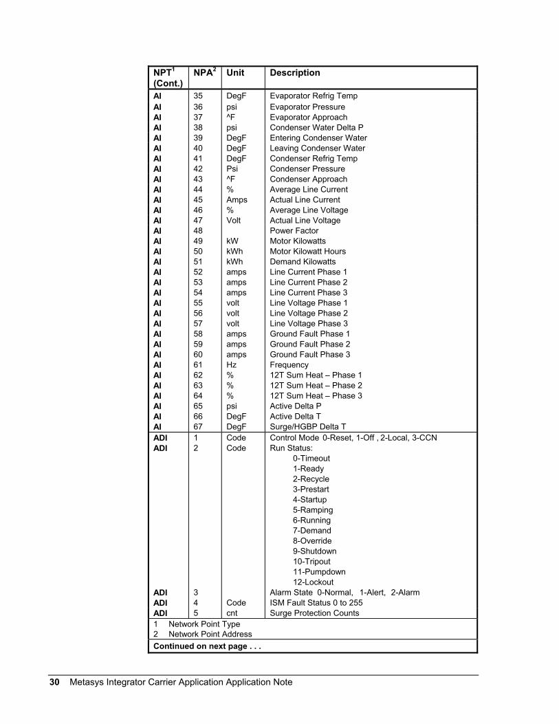
To get the hardware reference for mapping points to a CS object (via thesoftware model), combine the Network Point Type (NPT) and NetworkPoint Address (NPA). For example, the hardware reference for the ChilledWater Temp point is AI5.
The ADI points (internal parameters) cannot be mapped to standardobjects. To monitor the ADIs, map them to CS object AD attributes(which can then be mapped to standard AD objects).
Table 14: 19XR Hermetic Centrifugal Chiller (PICII) Points UsingDataPort Device
NPT1 NPA2 Unit DescriptionAI 1 % Active Demand LimitAI 2 Min Start Inhibit TimerAI 3 DegF Temperature ResetAI 4 DegF Control PointAI 5 DegF Chilled Water TempAI 6 % Average Line CurrentAI 7 % Motor Percent KilowattsAI 8 mA Auto Demand Limit InputAI 9 mA Auto Chilled Water ResetAI 10 DegF Remote Reset SensorAI 11 Total Compressor StartsAI 12 Starts in 12 HoursAI 13 Hour Service OntimeAI 14 mA Refrigerant Leak SensorAI 15 % Actual Guide Vane PosAI 16 psi Oil Pump Delta PAI 17 Hour Compressor OntimeAI 18 % Guide Vane DeltaAI 19 % Target Guide Vane PosAI 20 DegF Oil Sump TemperatureAI 21 DegF Oil Sump Delta PAI 22 DegF Comp Discharge TempAI 23 DegF Comp Thrust BRG TempAI 24 DegF Comp Motor Winding TempAI 25 DegF Spare Temp 1AI 26 DegF Spare Temp 2AI 27 % Diffuser ActuatorAI 28 % Target VFD SpeedAI 29 % Actual VFD SpeedAI 30 Psi Chilled Water Delta PAI 31 DegF Entering Chilled WaterAI 32 DegF Leaving Chilled WaterAI 33 ^F Chilled Water Delta TAI 34 ^F Chilled Water Pulldown/Min1 Network Point Type2 Network Point AddressContinued on next page . . .
19XR HermeticCentrifugalChiller (PICII)Points UsingDataPortDevice
30 Metasys Integrator Carrier Application Application Note
NPT1
(Cont.)NPA2 Unit Description
AI 35 DegF Evaporator Refrig TempAI 36 psi Evaporator PressureAI 37 ^F Evaporator ApproachAI 38 psi Condenser Water Delta PAI 39 DegF Entering Condenser WaterAI 40 DegF Leaving Condenser WaterAI 41 DegF Condenser Refrig TempAI 42 Psi Condenser PressureAI 43 ^F Condenser ApproachAI 44 % Average Line CurrentAI 45 Amps Actual Line CurrentAI 46 % Average Line VoltageAI 47 Volt Actual Line VoltageAI 48 Power FactorAI 49 kW Motor KilowattsAI 50 kWh Motor Kilowatt HoursAI 51 kWh Demand KilowattsAI 52 amps Line Current Phase 1AI 53 amps Line Current Phase 2AI 54 amps Line Current Phase 3AI 55 volt Line Voltage Phase 1AI 56 volt Line Voltage Phase 2AI 57 volt Line Voltage Phase 3AI 58 amps Ground Fault Phase 1AI 59 amps Ground Fault Phase 2AI 60 amps Ground Fault Phase 3AI 61 Hz FrequencyAI 62 % 12T Sum Heat – Phase 1AI 63 % 12T Sum Heat – Phase 2AI 64 % 12T Sum Heat – Phase 3AI 65 psi Active Delta PAI 66 DegF Active Delta TAI 67 DegF Surge/HGBP Delta TADI 1 Code Control Mode 0-Reset, 1-Off , 2-Local, 3-CCNADI 2 Code Run Status:
0-Timeout1-Ready2-Recycle3-Prestart4-Startup5-Ramping6-Running7-Demand8-Override9-Shutdown10-Tripout11-Pumpdown12-Lockout
ADI 3 Alarm State 0-Normal, 1-Alert, 2-AlarmADI 4 Code ISM Fault Status 0 to 255ADI 5 cnt Surge Protection Counts1 Network Point Type2 Network Point AddressContinued on next page . . .

Metasys Integrator Carrier Application Application Note 31
NPT1
(Cont.)NPA2 Unit Description
BI 1 Occupied 0-No, 1-YesBI 2 CCN Chiller Start/Stop 0-Stop, 1-StartBI 3 Remote Start Contact 0-Off, 1-OnBI 4 Ice Build Contact 0-Open, 1-CloseBI 5 Chilled Water Pump 0-Off, 1-OnBI 6 Chilled Water Flow 0-No, 1-YesBI 7 Condenser Water Pump 0-Off, 1-OnBI 8 Condenser Water Flow 0-No, 1-YesBI 9 Oil Pump Relay 0-Off, 1-OnBI 10 Compressor Start Relay 0-Off, 1-OnBI 11 Compressor Start Contact 0-Open, 1-CloseBI 12 Starter Trans Relay 0-Off, 1-OnBI 13 Compressor Run Contact 0-Open, 1-CloseBI 14 Tower Fan Relay Low 0-Off, 1-OnBI 15 Tower Fan Relay High 0-Off, 1-OnBI 16 Starter Fault 0-Alarm, 1-NormalBI 17 Spare Safety Input 0-Alarm, 1-NormalBI 18 Shunt Trip Relay 0-Off, 1-OnBI 19 Oil Heater Relay 0-Off, 1-OnBI 20 Hot Gas Bypass Relay 0-Off, 1-OnBI 21 Surge/HGBP Active 0-No, 1-YesBI 22 Single Cycle Dropout 0-Normal, 1-AlarmBI 23 Phase Loss 0-Normal, 1-AlarmBI 24 Overvoltage 0-Normal, 1-AlarmBI 25 Undervoltage 0-Normal, 1-AlarmBI 26 Current Unbalance 0-Normal, 1-AlarmBI 27 Voltage Unbalance 0-Normal, 1-AlarmBI 28 Overload Trip 0-Normal, 1-AlarmBI 29 Locked Rotor Trip 0-Normal, 1-AlarmBI 30 Start LRA Trip 0-Normal, 1-AlarmBI 31 Ground Fault 0-Normal, 1-AlarmBI 32 Phase Reversal 0-Normal, 1-AlarmBI 33 Frequency Out of Range 0-Normal, 1-AlarmBI 34 ISM Power on Reset 0-Normal, 1-AlarmBI 35 Phase 1 Fault 0-Normal, 1-AlarmBI 36 Phase 2 Fault 0-Normal, 1-AlarmBI 37 Phase 3 Fault 0-Normal, 1-AlarmBI 38 ICR Start Complete 0-False, 1-TrueBI 39 1M Start/Run Fault 0-Normal, 1-AlarmBI 40 2M Start/Run Fault 0-Normal, 1-AlarmBI 41 Pressure Trip Contact 0-Normal, 1-AlarmBI 42 Starter Fault 0-Normal, 1-Alarm1 Network Point Type2 Network Point AddressContinued on next page . . .

32 Metasys Integrator Carrier Application Application Note
NPT1
(Cont.)NPA2 Unit Description
BI 43 Motor Amperes Not Sensed 0-Normal, 1-AlarmBI 44 Start Acceleration Fault 0-Normal, 1-AlarmBI 45 High Motor Amperes 0-Normal, 1-AlarmBI 46 ICR Stop Complete 0-False, 1-TrueBI 47 1M/2M Stop Fault 0-Normal, 1-AlarmBI 48 Motor Amperes When Stopped 0-Normal, 1-AlarmBI 49 Hardware Failure 0-Normal 1-AlarmBI 50 System Alarm-Alert 0-False, 1-TrueBI 51 System Alarm-Alarm 0-False, 1-True1 Network Point Type2 Network Point Address

Metasys Integrator Carrier Application Application Note 33
To get the hardware reference for mapping points to a CS object (via thesoftware model), combine the Network Point Type (NPT) and NetworkPoint Address (NPA). For example, the hardware reference for the SupplyAir Temperature point is AI2.
Table 15: 48EJ, 48EK, 48EW, 48EY, 50EJ, 50EK, 50EW, and 50EY SinglePackage Rooftop Unit Point Mapping Using DataPort Device
NPT1 NPA2 Unit DescriptionAI 1 DegF Space TemperatureAI 2 DegF Supply Air TemperatureAI 3 DegF Return Air TemperatureAI 4 DegF Outside Air TemperatureAI 5 DegF Control SetpointAI 6 % Cooling Total CapacityAI 7 % Heating Total CapacityAI 8 % Economizer PositionAI 9 % IAQ Minimum Damper PositionAI 10 DegF SAT ResetAI 11 DegF Space Temperature OffsetAI 12 DegF Space Temperature ResetBI 1 Economizer Active 0-No, 1-YesBI 2 Supply Fan Status 0-No, 1-YesBI 3 Supply Fan Relay 0-No, 1-YesBI 4 Modulated Power Exhaust Enable 0-No, 1-YesBI 5 Filter Status 0-Clean, 1-DirtyBI 6 Field Applied Status 0-No, 1-YesBI 7 Remote Occupied Mode 0-No, 1-YesBI 8 Heat Stage 1 0-No, 1-YesBI 9 Enthalpy 0-No, 1-YesBI 10 Indoor Air Quality 0-No, 1-YesBI 11 Outdoor Air Quality 0-No, 1-YesBI 12 Alarm Warning Light 0-No, 1-YesBI 13 Demand Limit Switch 0-No, 1-YesBI 14 Evacuation 0-No, 1-YesBI 15 Pressurization 0-No, 1-YesBI 16 Smoke Purge 0-No, 1-YesBI 17 Fire Shutdown 0-No, 1-YesBI 18 Heat Stage 2 0-No, 1-YesBI 19 CV Power Exhaust Stage 1 0-No, 1-YesBI 20 CV Power Exhaust Stage 2 0-No, 1-YesBI 21 Heat Interlock Relay 0-No, 1-YesBI 22 Compressor 1 0-No, 1-YesBI 23 Compressor 1 Safety 0-No, 1-YesBI 24 Compressor 2 0-No, 1-YesBI 25 Compressor 2 Safety 0-No, 1-Yes1 Network Point Type2 Network Point AddressContinued on next page . . .
48EJ, 48EK,48EW, 48EY,50EJ, 50EK,50EW, and50EY SinglePackageRooftop UnitPoints UsingDataPortDevice

34 Metasys Integrator Carrier Application Application Note
NPT1
(Cont.)NPA2 Unit Description
BI 26 Unloader 1 0-No, 1-YesBI 27 Unloader 2 0-No, 1-YesBI 28 Outdoor Fan 1 0-No, 1-YesBI 29 Outdoor Fan 2 0-No, 1-YesBI 30 Y1 - Call for Cool 1 0-No, 1-YesBI 31 Y2 - Call for Cool 2 0-No, 1-YesBI 32 W1 - Call for Heat 1 0-No, 1-YesBI 33 W2 - Call for Heat 2 0-No, 1-YesBI 34 G - Call for Fan 0-No, 1-YesBI 35 Stage 1 Modulated Power Exhaust 0-No, 1-YesBI 36 Stage 2 Modulated Power Exhaust 0-No, 1-YesBI 37 Stage 3 Modulated Power Exhaust 0-No, 1-YesBI 38 Stage 4 Modulated Power Exhaust 0-No, 1-Yes1 Network Point Type2 Network Point Address
To get the hardware reference for mapping points to a CS object (via thesoftware model), combine the Network Point Type (NPT) and NetworkPoint Address (NPA). For example, the hardware references for MinutesLeft for Start is AI6.
Table 16: Carrier 30HX and 30GX Screw Chiller Using DataPort Device withoutComfortLink Controls. Carrier 30HX and 30GX Screw Chiller Using DataLINK Module withoutComfortLink Controls
NPT1 NPA2 Unit Description DataLINK ModuleReference PointName
AI 1 % Active Demand Limit DEM_LIMAI 2 DegF Water/Brine Setpoint SPAI 3 DegF Control Point CTRL_PNTAI 4 DegF Entering Fluid Temperature EWTAI 5 DegF Leaving Fluid Temperature LWTAI 6 min Minutes Left For Start min_left1 Network Point Type2 Network Point AddressContinued on next page . . .
Carrier 30HXand 30GXScrew ChillerUsing DataPortDevice orDataLINKmodule withoutComfortLinkControls
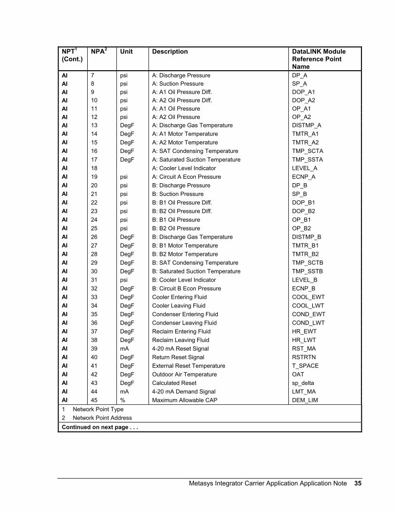
Metasys Integrator Carrier Application Application Note 35
NPT1
(Cont.)NPA2 Unit Description DataLINK Module
Reference PointName
AI 7 psi A: Discharge Pressure DP_AAI 8 psi A: Suction Pressure SP_AAI 9 psi A: A1 Oil Pressure Diff. DOP_A1AI 10 psi A: A2 Oil Pressure Diff. DOP_A2AI 11 psi A: A1 Oil Pressure OP_A1AI 12 psi A: A2 Oil Pressure OP_A2AI 13 DegF A: Discharge Gas Temperature DISTMP_AAI 14 DegF A: A1 Motor Temperature TMTR_A1AI 15 DegF A: A2 Motor Temperature TMTR_A2AI 16 DegF A: SAT Condensing Temperature TMP_SCTAAI 17 DegF A: Saturated Suction Temperature TMP_SSTAAI 18 A: Cooler Level Indicator LEVEL_AAI 19 psi A: Circuit A Econ Pressure ECNP_AAI 20 psi B: Discharge Pressure DP_BAI 21 psi B: Suction Pressure SP_BAI 22 psi B: B1 Oil Pressure Diff. DOP_B1AI 23 psi B: B2 Oil Pressure Diff. DOP_B2AI 24 psi B: B1 Oil Pressure OP_B1AI 25 psi B: B2 Oil Pressure OP_B2AI 26 DegF B: Discharge Gas Temperature DISTMP_BAI 27 DegF B: B1 Motor Temperature TMTR_B1AI 28 DegF B: B2 Motor Temperature TMTR_B2AI 29 DegF B: SAT Condensing Temperature TMP_SCTBAI 30 DegF B: Saturated Suction Temperature TMP_SSTBAI 31 psi B: Cooler Level Indicator LEVEL_BAI 32 DegF B: Circuit B Econ Pressure ECNP_BAI 33 DegF Cooler Entering Fluid COOL_EWTAI 34 DegF Cooler Leaving Fluid COOL_LWTAI 35 DegF Condenser Entering Fluid COND_EWTAI 36 DegF Condenser Leaving Fluid COND_LWTAI 37 DegF Reclaim Entering Fluid HR_EWTAI 38 DegF Reclaim Leaving Fluid HR_LWTAI 39 mA 4-20 mA Reset Signal RST_MAAI 40 DegF Return Reset Signal RSTRTNAI 41 DegF External Reset Temperature T_SPACEAI 42 DegF Outdoor Air Temperature OATAI 43 DegF Calculated Reset sp_deltaAI 44 mA 4-20 mA Demand Signal LMT_MAAI 45 % Maximum Allowable CAP DEM_LIM1 Network Point Type2 Network Point AddressContinued on next page . . .
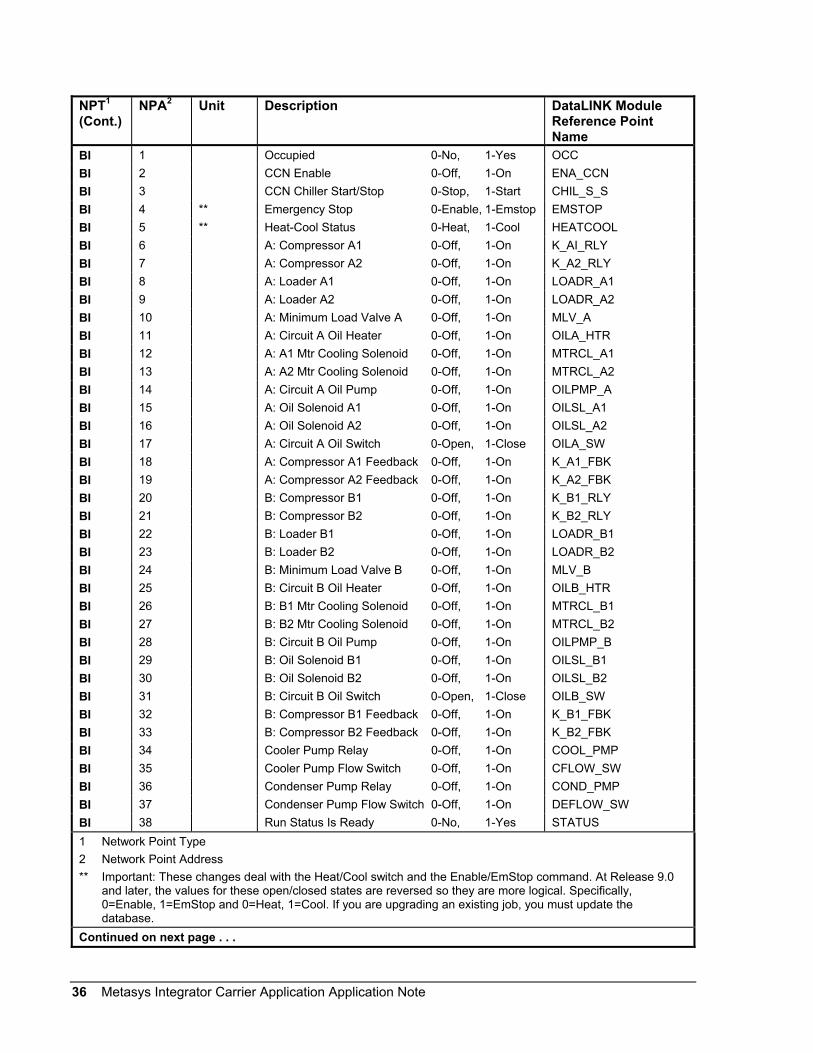
36 Metasys Integrator Carrier Application Application Note
NPT1
(Cont.)NPA2 Unit Description DataLINK Module
Reference PointName
BI 1 Occupied 0-No, 1-Yes OCCBI 2 CCN Enable 0-Off, 1-On ENA_CCNBI 3 CCN Chiller Start/Stop 0-Stop, 1-Start CHIL_S_SBI 4 ** Emergency Stop 0-Enable, 1-Emstop EMSTOPBI 5 ** Heat-Cool Status 0-Heat, 1-Cool HEATCOOLBI 6 A: Compressor A1 0-Off, 1-On K_AI_RLYBI 7 A: Compressor A2 0-Off, 1-On K_A2_RLYBI 8 A: Loader A1 0-Off, 1-On LOADR_A1BI 9 A: Loader A2 0-Off, 1-On LOADR_A2BI 10 A: Minimum Load Valve A 0-Off, 1-On MLV_ABI 11 A: Circuit A Oil Heater 0-Off, 1-On OILA_HTRBI 12 A: A1 Mtr Cooling Solenoid 0-Off, 1-On MTRCL_A1BI 13 A: A2 Mtr Cooling Solenoid 0-Off, 1-On MTRCL_A2BI 14 A: Circuit A Oil Pump 0-Off, 1-On OILPMP_ABI 15 A: Oil Solenoid A1 0-Off, 1-On OILSL_A1BI 16 A: Oil Solenoid A2 0-Off, 1-On OILSL_A2BI 17 A: Circuit A Oil Switch 0-Open, 1-Close OILA_SWBI 18 A: Compressor A1 Feedback 0-Off, 1-On K_A1_FBKBI 19 A: Compressor A2 Feedback 0-Off, 1-On K_A2_FBKBI 20 B: Compressor B1 0-Off, 1-On K_B1_RLYBI 21 B: Compressor B2 0-Off, 1-On K_B2_RLYBI 22 B: Loader B1 0-Off, 1-On LOADR_B1BI 23 B: Loader B2 0-Off, 1-On LOADR_B2BI 24 B: Minimum Load Valve B 0-Off, 1-On MLV_BBI 25 B: Circuit B Oil Heater 0-Off, 1-On OILB_HTRBI 26 B: B1 Mtr Cooling Solenoid 0-Off, 1-On MTRCL_B1BI 27 B: B2 Mtr Cooling Solenoid 0-Off, 1-On MTRCL_B2BI 28 B: Circuit B Oil Pump 0-Off, 1-On OILPMP_BBI 29 B: Oil Solenoid B1 0-Off, 1-On OILSL_B1BI 30 B: Oil Solenoid B2 0-Off, 1-On OILSL_B2BI 31 B: Circuit B Oil Switch 0-Open, 1-Close OILB_SWBI 32 B: Compressor B1 Feedback 0-Off, 1-On K_B1_FBKBI 33 B: Compressor B2 Feedback 0-Off, 1-On K_B2_FBKBI 34 Cooler Pump Relay 0-Off, 1-On COOL_PMPBI 35 Cooler Pump Flow Switch 0-Off, 1-On CFLOW_SWBI 36 Condenser Pump Relay 0-Off, 1-On COND_PMPBI 37 Condenser Pump Flow Switch 0-Off, 1-On DEFLOW_SWBI 38 Run Status Is Ready 0-No, 1-Yes STATUS1 Network Point Type2 Network Point Address** Important: These changes deal with the Heat/Cool switch and the Enable/EmStop command. At Release 9.0
and later, the values for these open/closed states are reversed so they are more logical. Specifically,0=Enable, 1=EmStop and 0=Heat, 1=Cool. If you are upgrading an existing job, you must update thedatabase.
Continued on next page . . .

Metasys Integrator Carrier Application Application Note 37
NPT1
(Cont.)NPA2 Unit Description DataLINK Module
Reference PointName
BD 1 Ice Valve 0-Off, 1-On ICE_VALVBD 2 Ice Build Complete 0-No, 1-Yes ICE_DONEBD 3 ** Heat/Cool Switch 0-Heat, 1-Cool HC_SWBD 4 Dual Setpoint Switch 0-Off, 1-On DUALBD 5 Cooler Heater Solenoid 0-Off, 1-On COOL_HTRBD 6 Demand Switch 1 0-Off, 1-On DMD_SW1BD 7 Demand Switch 2 0-Off, 1-On DMD_SW2BD 8 FAN_1 0-Off, 1-On FAN_1BD 9 FAN_2 0-Off, 1-On FAN_2BD 10 FAN_3 0-Off, 1-On FAN_3BD 11 FAN_4 0-Off, 1-On FAN_4BD 12 FAN_5 0-Off, 1-On FAN_5BD 13 FAN_6 0-Off, 1-On FAN_6ADI 1 Code Control Mode: MODE
0-LOCAL_ON1-CCN_ON2-CLOCK_ON3-EMSTOP4-DELAYOFF5-LOCALOFF6-CCN_OFF7-CLOCKOFF8-RESET
ADI 2 Code Run Status: STATUS0-Ready1-Off2-On3-Timeout4-Recycle5-Startup6-Ramping7-Running8-Demand9-Override10-Shutdown11-Abnormal12-Pumpdown13-Test
1 Network Point Type2 Network Point Address** Important: These changes deal with the Heat/Cool switch and the Enable/EmStop command. At Release 9.0
and later, the values for these open/closed states are reversed so they are more logical. Specifically,0=Enable, 1=EmStop and 0=Heat, 1=Cool. If you are upgrading an existing job, you must update thedatabase.
Continued on next page. . .

38 Metasys Integrator Carrier Application Application Note
NPT1
(Cont.)NPA2 Unit Description DataLINK Module
Reference PointName
ADI 3 Code Alarm State: ALM0-Normal1-Shutdown2-Alarm3-Partial
ADI 4 Code CCN Loadshed Signal: DL_STAT0-Normal1-Redline2-Shed
ADF 1 Code Current Alarm 1 alarm_1ADF 2 Code Current Alarm 2 alarm_2ADF 3 Code Current Alarm 3 alarm_3ADF 4 Code Current Alarm 4 alarm_4ADF 5 Code Current Alarm 5 alarm_5ADF 6 % Percent Total Capacity CAP_TADF 7 % A: Total Capacity CAPA_TADF 8 % A: Available Capacity CAPA_AADF 9 % A: EXV Percent Open EXV_AADF 10 % A: Motormaster Speed SPEED_AADF 11 % A: Water Valve Position WV_AADF 12 Volts A: CPM A1 Feedback K_A1_FBKADF 13 Volts A: CPM A2 Feedback K_A2_FBKADF 14 % B: Total Capacity CAPB_TADF 15 % B: Available Capacity CAPB_AADF 16 % B: EXV Percent Open EXV_BADF 17 % B: Motormaster Speed SPEED_BADF 18 Volts B: CPM B1 Feedback K_B1_FBKADF 19 Volts B: CPM B2 Feedback K_B2_FBKADF 20 DegF Options Temperature 1 OPT_TMP1ADF 21 DegF Options Temperature 2 OPT_TMP2
The following points apply to the DataLINK module only:BO 1* Chiller Start/Stop 0-Stop, 1-Start CHIL_S_SBO 2* ** Emergency Stop 0-Enable, 1-Emstop EMSTOPBO 3* CCN Enable 0-Off, 1-On ENA_CCN1 Network Point Type2 Network Point AddressContinued on next page . . .

Metasys Integrator Carrier Application Application Note 39
NPT1
(Cont.)NPA2 Unit Description DataLINK Module
Reference PointName
The following points apply to the DataLINK module only:AO 1 DegF Cooling Setpt 1 DegF 0-120 CSP1AO 2 DegF Cooling Setpt 2 DegF 0-120 CSP2AO 3 DegF Heating Setpt 1 DegF 0-120 HSP1AO 4 DegF Heating Setpt 1 DegF 0-120 HSP2AO 5 % Demand SW Setpt 1 0-100 dlswsp1AO 6 % Demand SW Setpt 2 0-100 dlswsp2AO 7 % Active Demand Limit 0-100 DEM_LIMAO 8 DegF Control Point DegF 0-120 CTRL_PNTAO 9 DegC Cooling Setpt 1 DegC -12-50 CSP1AO 10 DegC Cooling Setpt 2 DegC -12-50 CSP2AO 11 DegC Heating Setpt 1 DegC -12-50 HSP1AO 12 DegC Heating Setpt 2 DegC -12-50 HSP2AO 13 DegC Control Point DegC -12-50 CTRL_PNT1 Network Point Type2 Network Point Address* Control of this point can be released back to the controller.** Important: These changes deal with the Heat/Cool switch and the Enable/EmStop command. At Release 9.0
and later, the values for these open/closed states are reversed so they are more logical. Specifically,0=Enable, 1=EmStop and 0=Heat, 1=Cool. If you are upgrading an existing job, you must update thedatabase.

40 Metasys Integrator Carrier Application Application Note
To get the hardware reference for mapping points to a CS object (via thesoftware model), combine the Network Point Type (NPT) and NetworkPoint Address (NPA). For example, the hardware reference for theMinutes Left for Start point is AI6.
Table 17: Carrier 30HX/GX Screw Chiller Using DataLINK Module with ComfortLink ControlsNPT1 NPA2 Unit Description DataLINK Module
Reference PointName
AI 1 % Active Demand Limit DEM_LIMAI 2 DegF Water/Brine Setpoint SPAI 3 DegF Control Point CTRL_PNTAI 4 DegF Entering Fluid Temperature EWTAI 5 DegF Leaving Fluid Temperature LWTAI 6 min Minutes Left For Start MIN_LEFTAI 7 psi A: Discharge Pressure DP_AAI 8 psi A: Suction Pressure SP_AAI 9 psi A: A1 Oil Pressure Diff. DOP_A1AI 10 psi A: A2 Oil Pressure Diff. DOP_A2AI 11 psi A: A1 Motor Temperature OP_A1AI 12 psi A: A2 Motor Temperature OP_A2AI 13 DegF A: Discharges Gas Temperature DISTMP_AAI 14 DegF A: A1 Motor Temperature TMTR_A1AI 15 DegF A: A2 Motor Temperature TMTR_A2AI 16 DegF A: SAT Condensing Temperature TMP_SCTAAI 17 DegF A: Saturated Suction Temperature TMP_SSTAAI 18 A: Cooler Level Indicator LEVEL_AAI 19 psi A: Circuit Running Current A_CURRAI 20 DegF A: Suction Superheat Temperature SH_AAI 21 psi B: Discharge Pressure DP_BAI 22 psi B: Suction Pressure SP_BAI 23 psi B: B1 Oil Pressure Diff. DOP_B1AI 24 psi B: B2 Oil Pressure Diff. DOP_B2AI 25 psi B: B1 Oil Pressure OP_B1AI 26 psi B: B2 Oil Pressure OP_B2AI 27 DegF B Discharge Gas Temperature DISTMP_BAI 28 DegF B: B1 Motor Temperature TMTR_BIAI 29 DegF B: B2 Motor Temperature TMTR_B2AI 30 DegF B: SAT Condensing Temperature TMP_SCTBAI 31 DegF B: Saturated Suction Temperature TMP_SSTBAI 32 B: Cooler Level Indicator LEVEL_BAI 33 B: Circuit Running Current B_CURRAI 34 DegF B: Suction Superheat Temperature SH_BAI 35 DegF Cooler Entering Fluid COOL_EWTAI 36 DegF Cooler Leaving Fluid COOL_LWTAI 37 DegF Condenser Entering Fluid COND_EWTAI 38 DegF Condenser Leaving Fluid COND_LWT1 Network Point Type2 Network Point AddressContinued on next page . . .
Carrier30HX/GX ScrewChiller UsingDataLINKModule withComfortLinkControls

Metasys Integrator Carrier Application Application Note 41
NPT1
(Cont.)NPA2 Unit Description DataLINK Module
Reference PointName
AI 39 mA 4-20 mA Reset Signal RST_MAAI 40 DegF Outdoor Air Temperature OATAI 41 mA 4-20 mA Demand Signal LMT_MAAI 42 DegF Lead/Lag Leaving Fluid DUAL_LWTAI 43 DegF Space Temp SPTAI 44 mA 4-20 mA Cooling Setpoint CSP_INAI 45 mA 4-20 mA Heating Setpoint HSP_INAI 46 % Percent Total Capacity CAP_TAI 47 psi A: Economizer Pressure ECNP_AAI 48 psi B: Economizer Pressure ECNP_BBI 1 Occupied 0-No, 1-Yes OCCBI 2 Override Modes in Effect 0-Off, 1-On MODEBI 3 CCN Chiller Start/Stop 0-Stop, 1-Start CHIL_S_SBI 4 ** Emergency Stop 0-Enable, 1-Emstop EMSTOPBI 5 ** Heat-Cool Status 0-Heat, 1-Cool HEATCOOLBI 6 A: Compressor A1 0-Off, 1-On K_A1_RLYBI 7 A: Compressor A2 0-Off, 1-On K_A2_RLYBI 8 A: Loader AI 0-Off, 1-On LOADR_A1BI 9 A: Loader A2 0-Off, 1-On LOADR_A2BI 10 A: Minimum Load Valve A 0-Off, 1-On MLV_ABI 11 A: Circuit A Oil Heater 0-Off, 1-On OILA_HTRBI 12 A: A1 Mtr Cooling Solenoid 0-Off, 1-On MTRCL_A1BI 13 A: A2 Mtr Cooling Solenold 0-Off, 1-On MTRCL_A2BI 14 A: Circuit A Oil Pump 0-Off, 1-On OILPMP_ABI 15 A: Oil Solenold A1 0-Off, 1-On OILSL_A1BI 16 A: Oil Solenoid A2 0-Off, 1-On OILSL_A2BI 17 A: Circuit A Oil Switch 0-Open, 1-Close OILA_SWBI 18 A: Compressor AI Feedback 0-Off, 1-On K_A1_FBKBI 19 A: Compressor A2 Feedback 0-Off, 1-On K_A2_FBKBI 20 Run Status Is On 0-No, 1-Yes STATBI 21 B: Compressor B1 0-Off, 1-On K_B1_RLYBI 22 B: Compressor B2 0-Off, 1-On K_B2_RLYBI 23 B: Loader B1 0-Off, 1-On LOADR_B1BI 24 B: Loader B2 0-Off, 1-On LOADR_B2BI 25 B: Minimum Load Valve B 0-Off, 1-On MLV_BBI 26 B: Circuit B Oil Heater 0-Off, 1-On OILB_HTRBI 27 B: B1 Mtr Cooling Solenoid 0-Off, 1-On MTRCL_B1BI 28 B: B2 Mtr Cooling Solenoid 0-Off, 1-On MTRCL_B2BI 29 B: Circuit B Oil Pump 0-Off, 1-On OILPMP_BBI 30 B: Oil Solenoid B1 0-Off, 1-On OILSL_B1BI 31 B: Oil Solenoid B2 0-Off, 1-On OILSL_B2BI 32 B: Circuit B Oil Switch 0-Open, 1-Close OILB_SWBI 33 B: Compressor B1 Feedback 0-Off, 1-On K_B1_FBKBI 34 B: Compressor B2 Feedback 0-Off, 1-On K_B2_FBK1 Network Point Type2 Network Point Address** Important: These changes deal with the Heat/Cool switch and the Enable/EmStop command. At Release 9.0
and later, the values for these open/closed states are reversed so they are more logical. Specifically,0=Enable, 1=EmStop and 0=Heat, 1=Cool. If you are upgrading an existing job, you must update thedatabase.
Continued on next page . . .

42 Metasys Integrator Carrier Application Application Note
NPT1
(Cont.)NPA2 Unit Description DataLINK Module
Reference PointName
BI 35 Cooler Pump Relay 0-Off, 1-On COOL_PMPBI 36 Cooler Pump Flow Switch 0-Off, 1-On COOLFLOWBI 37 Condenser Pump Relay 0-Off, 1-On COND_PMPBI 38 Condenser Pump Flow Switch 0-Off, 1-On CONDFLOWBD 1 Fan 1 Relay 0-Off, 1-On FAN_1BD 2 Fan 2 Relay 0-Off, 1-On FAN_2BD 3 ** Fan 3 Relay 0-Off, 1-On FAN_3BD 4 Fan 4 Relay 0-Off, 1-On FAN_4BD 5 Demand Switch 1 0-Off, 1-On DMD_SW1BD 6 Demand Switch 2 0-Off, 1-On DMD_SW2BD 7 Ice Build Complete 0-Off, 1-On ICEBD 8 Dual Setpoint Switch 0-Off, 1-On DUAL_INBD 9 Cooler Heater Solenoid 0-Off, 1-On COOL_HTRADI 1 Code Control Mode: 0-Off, 1-On, 2-TEST STATADI 2 Code Control Mode: STAT
0-Test1-Emrgcy (Second Field)2-Local3-CCN4-Clock
ADI 3 Code Alarm State: 0-Normal, 1-Alert, 2-Alarm ALMADI 4 Code CCN Loadshed Signal: 0-Normal, 1-Redline,
2-ShedDL-STAT
ADF 1 % A: Total Capacity CAPA_TADF 2 % A: Available Capacity CAPA_AADF 3 % A: EXV Percent Open EXV_AADF 4 % A: Vari Head Press Pct VHPAADF 5 Amps Comp A1 Running Current A1_CURRADF 6 Amps Comp A1 % Must Trip Amps A1_MTAADF 7 Amps Comp A2 Running Current A2_CURRADF 8 Amps Comp A2 % Must Trip Amps A2_MTAADF 9 % B: Total Capacity CAPB_TADF 10 % B: Available Capacity CAPB_AADF 11 % B: EXV Percent Open EXV_BADF 12 % B: Vari Head Press Pct VHPBADF 13 Amps Comp B1 Running Current B1_CURRADF 14 Amps Comp B1 % Must Trip Amps B1_MTAADF 15 Amps Comp B2 Running Current B2_CURRADF 16 Amps Comp B2 % Must Trip Amps B2_MTA1 Network Point Type2 Network Point Address* Control of this point can be released back to the controller.** Important: These changes deal with the Heat/Cool switch and the Enable/EmStop command. At Release 9.0
and later, the values for these open/closed states are reversed so they are more logical. Specifically,0=Enable, 1= EmStop and 0=Heat, 1=Cool. If you are upgrading an existing job, you must update thedatabase.
Continued on next page . . .
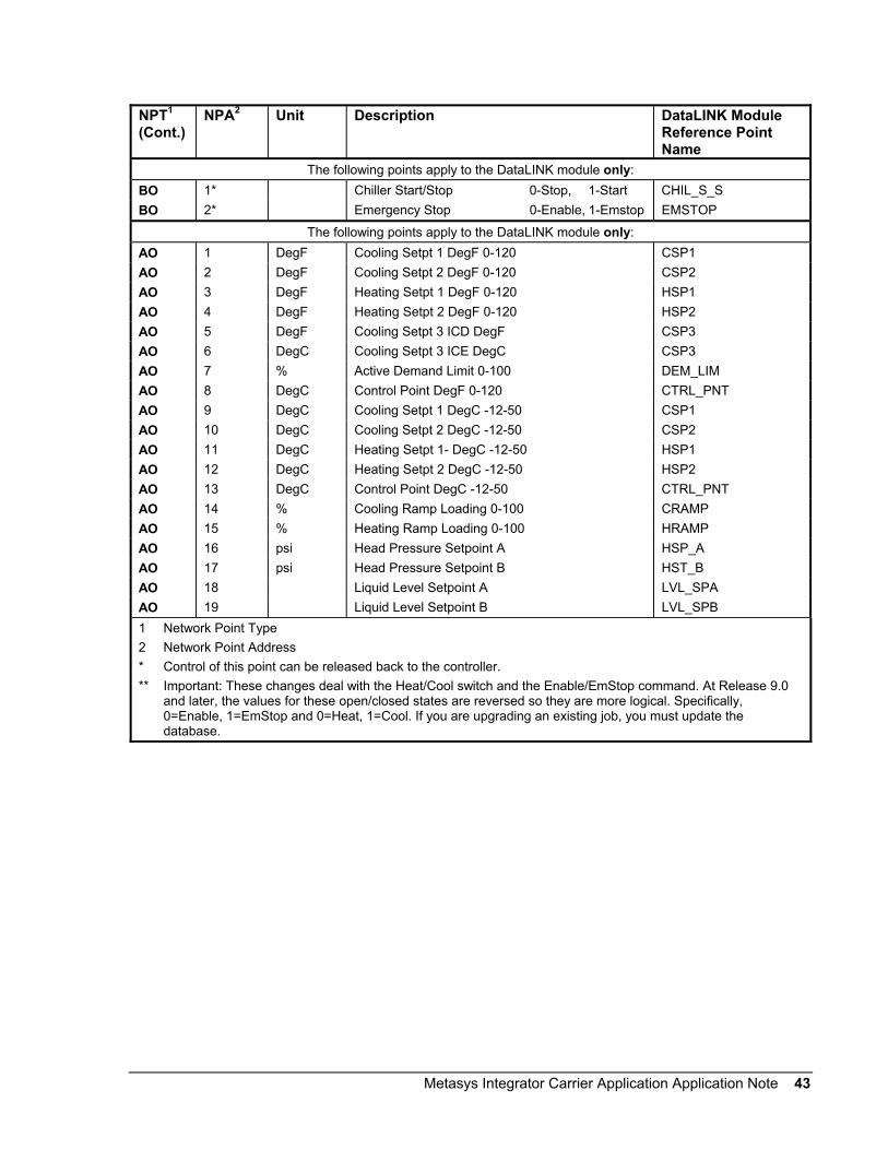
Metasys Integrator Carrier Application Application Note 43
NPT1
(Cont.)NPA2 Unit Description DataLINK Module
Reference PointName
The following points apply to the DataLINK module only:BO 1* Chiller Start/Stop 0-Stop, 1-Start CHIL_S_SBO 2* Emergency Stop 0-Enable, 1-Emstop EMSTOP
The following points apply to the DataLINK module only:AO 1 DegF Cooling Setpt 1 DegF 0-120 CSP1AO 2 DegF Cooling Setpt 2 DegF 0-120 CSP2AO 3 DegF Heating Setpt 1 DegF 0-120 HSP1AO 4 DegF Heating Setpt 2 DegF 0-120 HSP2AO 5 DegF Cooling Setpt 3 ICD DegF CSP3AO 6 DegC Cooling Setpt 3 ICE DegC CSP3AO 7 % Active Demand Limit 0-100 DEM_LIMAO 8 DegC Control Point DegF 0-120 CTRL_PNTAO 9 DegC Cooling Setpt 1 DegC -12-50 CSP1AO 10 DegC Cooling Setpt 2 DegC -12-50 CSP2AO 11 DegC Heating Setpt 1- DegC -12-50 HSP1AO 12 DegC Heating Setpt 2 DegC -12-50 HSP2AO 13 DegC Control Point DegC -12-50 CTRL_PNTAO 14 % Cooling Ramp Loading 0-100 CRAMPAO 15 % Heating Ramp Loading 0-100 HRAMPAO 16 psi Head Pressure Setpoint A HSP_AAO 17 psi Head Pressure Setpoint B HST_BAO 18 Liquid Level Setpoint A LVL_SPAAO 19 Liquid Level Setpoint B LVL_SPB1 Network Point Type2 Network Point Address* Control of this point can be released back to the controller.** Important: These changes deal with the Heat/Cool switch and the Enable/EmStop command. At Release 9.0
and later, the values for these open/closed states are reversed so they are more logical. Specifically,0=Enable, 1=EmStop and 0=Heat, 1=Cool. If you are upgrading an existing job, you must update thedatabase.

44 Metasys Integrator Carrier Application Application Note
To get the hardware reference for mapping points to a CS object (via thesoftware model), combine the Network Point Type (NPT) and NetworkPoint Address (NPA). For example, the hardware reference for theMinutes Left for Start point is AI6.
Table 18: Carrier 30RA AquaSnap Chiller Using DataLINK Module withComfortLink ControlsNPT1 NPA2 Unit Description DataLINK
moduleReferencePoint Name
AI 1 % Active Demand Limit DEM_LIMAI 2 DegF Active Setpoint SPAI 3 DegF Control Point CTRL_PNTAI 4 DegF Entering Fluid Temperature EWTAI 5 DegF Leaving Fluid Temperature LWTAI 6 min Minutes Left For Start MIN_LEFTAI 7 psi A: Discharge Pressure DP_AAI 8 psi A: Suction Pressure SP_AAI 9 DegF A: SAT Condensing Temperature TMP_SCTAAI 10 DegF A: Saturated Suction Temperature TMP_SSTAAI 11 psi B: Discharge Pressure DP_BAI 12 psi B: Suction Pressure SP_BAI 13 DegF B: SAT Condensing Temperature TMP_SCTBAI 14 DegF B: Saturated Suction Temp TMP_SSTBAI 15 DegF Cooler Entering Fluid COOL_EWTAI 16 DegF Cooler Leaving Fluid COOL_LWTAI 17 DegF A: Suction Superheat Temperature SH_AAI 18 MA 4-20ma Reset Signal RST_MAAI 19 DegF B: Suction Superheat Temperature SH_BAI 20 DegF Outdoor Air Temperature OATAI 21 DegF Lead/Lag Leaving Fluid DUAL_LWTAI 22 MA 4-20ma Demand Signal LMT_MAAI 23 DegF Space Temperature SPTAI 24 DegF A: Calc HP Setpoint HSP_AAI 25 DegF A: Comp Return Gas Temp TMP_RGTAAI 26 DegF B: Calc HP Setpoint HSP_BAI 27 DegF B: Comp Return Gas Temp TMP_RGTBAI 28 DegF Cooler LWT Setpoint LWT_SP1 Network Point Type2 Network Point AddressContinued on next page . . .
Carrier 30RAAquaSnapChiller UsingDataLINKModule withComfortLinkControls

Metasys Integrator Carrier Application Application Note 45
NPT1
(Cont.)NPA2 Unit Description DataLINK
ModuleReferencePoint Name
BI 1 Occupied 0-No, 1-Yes OCCBI 2 Override Modes in Effect 0-Off,1-On MODEBI 3 CCN Chiller Start/Stop 0-Stop, 1-Start CHIL_S_SBI 4 ** Emergency Stop 0-Enable, 1-Emstop EMSTOPBI 5 ** Heat-Cool Status 0-Heat, 1-Cool HC_SELBI 6 A: Compressor A1 0-Off, 1-On K_AI_RLYBI 7 A: Compressor A2 0-Off, 1-On K_A2_RLYBI 8 Cooler Pump 1 Relay 0-Off, 1-On COOLPMP1BI 9 Cooler Pump 2 Relay 0-Off, 1-On COOLPMP2BI 10 Cooler Pump 1 Interlock 0-Off, 1-On PMP_FBKBI 11 Cooler Pump 2 Interlock 0-Off, 1-On PMP2_FBKBI 12 Cooler Flow Switch 0-Off, 1-On COOLFLOWBI 13 Rotate Cooler Pumps 0-Off, 1-On ROT_PUMPBI 14 A: Min Load Vlv Relay 0-Off, 1-On MLV_RLYBI 15 A: Comp A1 Feedback 0-Off, 1-On K_AI_FBKBI 16 A: Comp A2 Feedback 0-Off, 1-On K_A2_FBKBI 17 B: Compressor B1 Relay 0-Off, 1-On K_B1_RLYBI 18 B: Compressor B2 Relay 0-Off, 1-On K_B2_RLYBI 19 B: Compressor B1 Feedback 0-Off,1-On K_B1_FBKBI 20 B: Compressor B2 Feedback 0-Off,1-On K_B2_FBKBI 21 B: Min Load VLV Relay 0-Off, 1-On MLV_RLY1 Network Point Type2 Network Point Address** Important: These changes deal with the Heat/Cool switch and the Enable/EmStop
command. At Release 9.0 and later, the values for these open/closed states arereversed so they are more logical. Specifically, 0=Enable, 1=EmStop and 0=Heat,1=Cool. If you are upgrading an existing job, you must update the database.
Continued on next page . . .
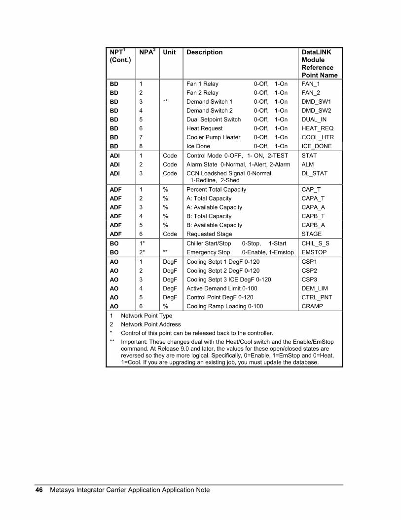
46 Metasys Integrator Carrier Application Application Note
NPT1
(Cont.)NPA2 Unit Description DataLINK
ModuleReferencePoint Name
BD 1 Fan 1 Relay 0-Off, 1-On FAN_1BD 2 Fan 2 Relay 0-Off, 1-On FAN_2BD 3 ** Demand Switch 1 0-Off, 1-On DMD_SW1BD 4 Demand Switch 2 0-Off, 1-On DMD_SW2BD 5 Dual Setpoint Switch 0-Off, 1-On DUAL_INBD 6 Heat Request 0-Off, 1-On HEAT_REQBD 7 Cooler Pump Heater 0-Off, 1-On COOL_HTRBD 8 Ice Done 0-Off, 1-On ICE_DONEADI 1 Code Control Mode 0-OFF, 1- ON, 2-TEST STATADI 2 Code Alarm State 0-Normal, 1-Alert, 2-Alarm ALMADI 3 Code CCN Loadshed Signal 0-Normal,
1-Redline, 2-ShedDL_STAT
ADF 1 % Percent Total Capacity CAP_TADF 2 % A: Total Capacity CAPA_TADF 3 % A: Available Capacity CAPA_AADF 4 % B: Total Capacity CAPB_TADF 5 % B: Available Capacity CAPB_AADF 6 Code Requested Stage STAGEBO 1* Chiller Start/Stop 0-Stop, 1-Start CHIL_S_SBO 2* ** Emergency Stop 0-Enable, 1-Emstop EMSTOPAO 1 DegF Cooling Setpt 1 DegF 0-120 CSP1AO 2 DegF Cooling Setpt 2 DegF 0-120 CSP2AO 3 DegF Cooling Setpt 3 ICE DegF 0-120 CSP3AO 4 DegF Active Demand Limit 0-100 DEM_LIMAO 5 DegF Control Point DegF 0-120 CTRL_PNTAO 6 % Cooling Ramp Loading 0-100 CRAMP1 Network Point Type2 Network Point Address* Control of this point can be released back to the controller.** Important: These changes deal with the Heat/Cool switch and the Enable/EmStop
command. At Release 9.0 and later, the values for these open/closed states arereversed so they are more logical. Specifically, 0=Enable, 1=EmStop and 0=Heat,1=Cool. If you are upgrading an existing job, you must update the database.

Metasys Integrator Carrier Application Application Note 47
To get the hardware reference for mapping points to a CS object (via thesoftware model), combine the Network Point Type (NPT) and NetworkPoint Address (NPA). For example, the hardware reference for the ServiceOntime point is AI15.
The ADI points (internal parameters) cannot be mapped to standardobjects. To monitor the ADIs, map them to CS object AD attributes(which can then be mapped to standard AD objects).
Table 19: 16JT Absorption Chiller Points Using DataPort DeviceNPT1 NPA2 Unit DescriptionAI 1 DegF Cooling SetpointAI 2 DegF Control PointAI 3 DegF Entering Chilled Water TempAI 4 DegF Leaving Chilled Water TempAI 5 DegF Target Capacity ValueAI 6 DegF Actual Capacity ValueAI 7 mA Temp Reset 4 to 20 mAAI 8 DegF Remote Reset SensorAI 9 Common Supply SensorAI 10 Common Return SensorAI 11 Desolid Time LeftAI 12 psi Solution Pump 1 PressureAI 13 psi Solution Pump 2 PressureAI 14 Hour Solution Pump OntimeAI 15 Hour Service OntimeAI 16 cnt Solution Pump StartsAI 17 cnt G1 HiLev Starts-Last HrAI 18 D/mn CHW_IN Pulldown Deg/MinAI 19 D/mn CHW OUT Pulldwon Deg/MinAI 20 DegF Refrigerant TempAI 21 Refrigerant Level SensorAI 22 Concentration LevelAI 23 Cooling Water Ent AbsorbAI 24 CLW Pulldown Deg/MinAI 25 Cooling Water Ent AbsorbAI 26 Recirc LiBr Ent SpraysAI 27 Weak LiBr Leaving AbsorbAI 28 Weak LiBr Lvg Low HX2AI 29 Weak LiBr Lvg High HX1AI 30 G2 LiBr Overflow PipeAI 31 Cooling Water Leaving GroundAI 32 Vapor Condensate TempAI 33 G1 Internal PressureAI 34 Strong LiBr Leaving GelAI 35 Weak LiBr Lvg LCD BoxAI 36 Strong LiBr Lvg High HX1AI 37 Strong LiBr Lvg G21 Network Point Type2 Network Point AddressContinued on next page . . .
16JTAbsorptionChiller PointsUsing DataPortDevice

48 Metasys Integrator Carrier Application Application Note
NPT1
(Cont.)NPA2 Unit Description
ADI 1 Code Control Mode 0=Reset, 1=Off, 2=Local,3=CCNADI 2 Code Run Status:
0=Timeout1=Ready2=Recycle3=Prestart4=Startup5=Ramping6=Running7=Demand8=Override9=Shutdown10=Tripout11=Pumpdown12=Lockout
BI 1 Occupied 0-No, 1-YesBI 2 CCN Chiller Start/Stop 0-Stop, 1-StartBI 3 Alarm State 0-No, 1-YesBI 4 Remote Start Contact 0-Open, 1-CloseBI 5 Startup Pulldown Failure 0-No, 1-YesBI 6 Chilled Run Relay 0-Off, 1-OnBI 7 Spare Prot Limit Input 0-Off, 1-OnBI 8 Desolidification Mode 0-No, 1-YesBI 9 Chilled Water Pump 0-Off, 1-OnBI 10 Chilled Water Flow 0-No, 1-YesBI 11 Cooling Water Pump 0-Off, 1-OnBI 12 Cooling Water Flow 0-No, 1-YesBI 13 Refrigerant Pump 0-Off, 1-OnBI 14 Ref Pum Overld/Hi Temp 0-No, 1-YesBI 15 Solution and Spray Pumps 0-Off, 1-OnBI 16 Sol Pump1 Overld/Hi Temp 0-Normal, 1-AlarmBI 17 Sol Pump2 Overld/Hi Temp 0-Normal, 1-AlarmBI 18 Spray Pump Overld/Hi Temp 0-Normal, 1-AlarmBI 19 Cycle Guard Auto/Manual 0-Off, 1-OnBI 20 Cycle Guard Valve 0-Off, 1-OnBI 21 Low Level Switch 0-Off, 1-OnBI 22 Cycle Guard Level Switch 0-Alarm, 1-NormalBI 23 Dilution Level Switch 0-Alarm, 1-NormalBI 24 High Level Switch 0-Alarm, 1-NormalBI 25 Low Chilled Water Temp 0-Alarm, 1-NormalBI 26 Tower Fan Relay 0-Off, 1-OnBI 27 G1 High LiBr Level 0-Alarm, 1-NormalBI 28 Generator Hi Temp/Press 0-Alarm, 1-Normal1 Network Point Type2 Network Point Address

Metasys Integrator Carrier Application Application Note 49
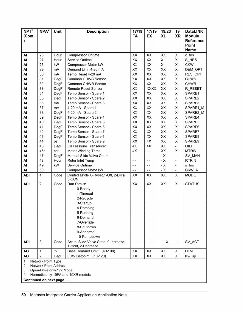
To get the hardware reference for mapping points to a CS object (via thesoftware model), combine the Network Point Type (NPT) and NetworkPoint Address (NPA). For example, the hardware reference for the ActiveDemand Limit is AI2.
Table 20: Point Mapping for 17FA, 19FA, 17EX, 19EX, 19XL, 19XR with PICI Controllers, 23XL withPICI Chillers Using DataLINK ModuleNPT1 NPA2 Unit Description 17/19
FA17/19EX
19/23XL
19XR
DataLINKModuleReferencePointName
AI 1 % Base Demand Limit XX XX XX X DLMAI 2 % Active Demand Limit XX XX XX X DEM_LIMAI 3 % Compressor Motor Load XX XX XX X CA_LAI 4 % Compressor Motor Current XX XX XX X CA_PAI 5 Amps Compressor Motor Amps XX XX XX X CA_AAI 6 % Target Guide Vane Position XX XX X- X GV_TRGAI 7 % Actual Guide Vane Position XX XX X- X GV_ACTAI 8 DegF Water/Brine Setpoint XX XX XX X SPAI 9 DegF Water/Brine Control Point XX XX XX X LCW_STPTAI 10 DegF Entering Chilled Water XX XX XX X ECWAI 11 DegF Leaving Chilled Water XX XX XX X LCWAI 12 DegF Entering Condenser Water XX XX XX X ECDWAI 13 DegF Leaving Condenser Water XX XX XX X LCDWAI 14 DegF Evaporator Refrig Temp XX XX XX X ERTAI 15 psi Evaporator Pressure XX XX XX X ERPAI 16 DegF Condenser Refrig Temp XX XX XX X CRTAI 17 psi Condenser Pressure XX XX XX X CRPAI 18 DegF Discharge Temperature XX XX XX X CMPDAI 19 DegF Bearing Temperature XX XX XX X MTRBAI 20 DegF Oil Sump Temperature XX XX XX X OILTAI 21 psi Oil Pressure XX XX XX X OILPDAI 22 % Line Voltage Percent XX XX XX X V_PAI 23 Volt Line Voltage Actual XX XX XX X V_AAI 24 # Total Compressor Starts XX XX XX X c_startsAI 25 # Starts In 12 Hours XX XX XX X STARTS1 Network Point Type2 Network Point Address3 Open-Drive only 17x Model4 Hermetic only 19FA and 19XR modelsContinued on next page . . .
17FA, 19FA,17EX, 19EX,19XL, 19XRwith PICIControllers,and 23XL withPICI ChillerPoints UsingDataLINKModule
50 Metasys Integrator Carrier Application Application Note
NPT1
(Cont.)
NPA2 Unit Description 17/19FA
17/19EX
19/23XL
19XR
DataLINKModuleReferencePointName
AI 26 Hour Compressor Ontime XX XX XX X c_hrsAI 27 Hour Service Ontime XX XX X- X S_HRSAI 28 kW Compressor Motor kW XX XX X- X CKWAI 29 mA Demand Limit 4-20 mA XX XX XX X DEM_OPTAI 30 mA Temp Reset 4-20 mA XX XX XX X RES_OPTAI 31 DegF Common CHWS Sensor XX XX XX X CHWSAI 32 DegF Common CHWR Sensor XX XX XX X CHWRAI 33 DegF Remote Reset Sensor XX XXXX XX X R_RESETAI 34 DegF Temp Sensor - Spare 1 XX XX XX X SPARE1AI 35 DegF Temp Sensor - Spare 2 XX XX XX X SPARE2AI 36 mA Temp Sensor - Spare 3 XX XX XX X SPARE3AI 37 mA 4-20 mA - Spare 1 XX XX XX X SPARE1_MAI 38 DegF 4-20 mA - Spare 2 XX XX XX X SPARE2_MAI 39 DegF Temp Sensor - Spare 4 XX XX XX X SPARE4AI 40 DegF Temp Sensor - Spare 5 XX XX XX X SPARE5AI 41 DegF Temp Sensor - Spare 6 XX XX XX X SPARE6AI 42 DegF Temp Sensor - Spare 7 XX XX XX X SPARE7AI 43 DegF Temp Sensor - Spare 8 XX XX XX X SPARE8AI 44 psi Temp Sensor - Spare 9 XX 4X XX X SPARE9AI 45 DegF Oil Pressure Transducer 4X 4X XX - OILPAI 46* cnt Motor Winding Temp 4X - - XX X MTRWAI 47 DegF Manual Slide Valve Count - - - - X - SV_MANAI 48 Hour Rotor Inlet Temp - - - - - X - RTRINAI 49 kW Service Ontime - - - - - X - s_hrsAI 50 Compressor Motor kW - - - - - X - CKW_AADI 1 Code Control Mode 0-Reset,1-Off, 2-Local,
3-CCNXX XX XX X MODE
ADI 2 Code Run Status: XX XX XX X STATUS0-Ready1-Timeout2-Recycle3-Startup4-Ramping5-Running6-Demand7-Override8-Shutdown9-Abnormal10-Pumpdown
ADI 3 Code Actual Slide Valve State: 0-Increase,1-Hold, 2-Decrease
- - - - - X - SV_ACT
AO 1 % Base Demand Limit (40-100) XX XX XX X DLMAO 2 DegF LCW Setpoint (10-120) XX XX XX X lcw_sp1 Network Point Type2 Network Point Address3 Open-Drive only 17x Model4 Hermetic only 19FA and 19XR modelsContinued on next page . . .

Metasys Integrator Carrier Application Application Note 51
NPT1
(Cont.)
NPA2 Unit Description 17/19FA
17/19EX
19/23XL
19XR
DataLINKModuleReferencePointName
AO 3 DegF ECW Setpoint (10-120) XX XX XX X ecw_spAO 4 DegF ICE BUILD Setpoint (15-60) XX XX XX X icw_spBI 1 Occupied 0-No, 1-Yes XX XX XX X OCCBI 2 Alarm State 0-Normal,1-Alarm XX XX XX X ALMBI 3 Chiller Start/Stop 0-Stop, 1-Start XX XX XX X CHIL_S_SBI 4 Motor High Temp Cutout
0-Normal,1-AlarmX3 X3 - - - MTRW
BI 5 Remote Contacts Input 0-Off, 1-On XX XX XX X REMCONBI 6 Hot Gas Bypass Relay 0-Off, 1-On XX XX XX X HGBRBI 7 Chilled Water Pump 0-Off, 1-On XX XX XX X CHWPBI 8 Chilled Water Flow 0-No, 1-Yes XX XX XX X EVFLBI 9 Condenser Water Pump 0-Off, 1-On XX XX XX X CDPBI 10 Condenser Water Flow 0-No, 1-Yes XX XX XX X CDFLBI 11 Compressor Start Relay 0-Off, 1-On XX XX XX X CMPRBI 12 Compressor Start Contact
0-Open, 1-CloseXX XX XX X 1CR_AUX
BI 13 Compressor Run Contact0-Open, 1-Close
XX XX XX X RUN_AUX
BI 14 Starter Fault Contact 0-Open, 1-Close XX XX XX X STR_FLTBI 15 Pressure Trip Contact
0-Open, 1-CloseXX XX XX X PRS_TRIP
BI 16 Single Cycle Dropout0-Normal, 1-Alarm
XX XX XX X V1_CYCLE
BI 17 Oil Pump Relay 0-Off, 1-On XX XX X- X OILRBI 18 Oil Heater Relay 0-Off, 1-On XX XX XX X OILHBI 19 Aux Oil Pump Relay 0-Off, 1-On X3 X3 - - - AUXOILRBI 20 Tower Fan Relay 0-Off, 1-On XX XX XX X TFRBI 21 Compressor Shunt Trip Relay
0-Of f , 1-OnXX XX XX X TRIPR
BI 22 Alarm Relay 0-Normal, 1-Alarm XX XX XX X ALMBI 23 Spare Protect Limit Input
0-Normal, 1-AlarmXX XX XX X SPR_PL
BI 24 Motor Cooling Relay 0-Off, 1-On 4X 4X X- X MTRCBI 25 Run Status Is Ready 0-No, 1-Yes XX XX XX X STATUSBI 26 Slide Valve Increase 0-Off, 1-On - - - - -X - SV_INCBI 27 Slide Valve Decrease 0-Off, 1-On - - - - -X - SV_DECBI 28 Variable Inlet Relay 0-Off, 1-On - - - - -X - VIRBI 29 Oil Safety Sensor 0-Open, 1-Close - - - - -X - OILSSBO 1 Chiller Start/Stop 0-Stop, 1-Start XX XX XX X CHIL_S_SBO 2 Remote Contacts Input 0-Off, 1-On XX XX XX X REMCON1 Network Point Type2 Network Point Address3 Open-Drive only 17x Model4 Hermetic only 19FA and 19XR models* Applicable only for 19XR Version 1.
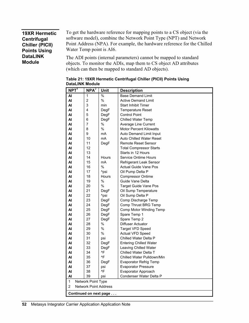
52 Metasys Integrator Carrier Application Application Note
To get the hardware reference for mapping points to a CS object (via thesoftware model), combine the Network Point Type (NPT) and NetworkPoint Address (NPA). For example, the hardware reference for the ChilledWater Temp point is AI6.
The ADI points (internal parameters) cannot be mapped to standardobjects. To monitor the ADIs, map them to CS object AD attributes(which can then be mapped to standard AD objects).
Table 21: 19XR Hermetic Centrifugal Chiller (PICII) Points UsingDataLINK Module
NPT1 NPA2 Unit DescriptionAI 1 % Base Demand LimitAI 2 % Active Demand LimitAI 3 min Start Inhibit TimerAI 4 DegF Temperature ResetAI 5 DegF Control PointAI 6 DegF Chilled Water TempAI 7 % Average Line CurrentAI 8 % Motor Percent KilowattsAI 9 mA Auto Demand Limit InputAI 10 mA Auto Chilled Water ResetAI 11 DegF Remote Reset SensorAI 12 Total Compressor StartsAI 13 Starts in 12 HoursAI 14 Hours Service Ontime HoursAI 15 mA Refrigerant Leak SensorAI 16 % Actual Guide Vane PosAI 17 ^psi Oil Pump Delta PAI 18 Hours Compressor OntimeAI 19 % Guide Vane DeltaAI 20 % Target Guide Vane PosAI 21 DegF Oil Sump TemperatureAI 22 ^psi Oil Sump Delta PAI 23 DegF Comp Discharge TempAI 24 DegF Comp Thrust BRG TempAI 25 DegF Comp Motor Winding TempAI 26 DegF Spare Temp 1AI 27 DegF Spare Temp 2AI 28 % Diffuser ActuatorAI 29 % Target VFD SpeedAI 30 % Actual VFD SpeedAI 31 psi Chilled Water Delta PAI 32 DegF Entering Chilled WaterAI 33 DegF Leaving Chilled WaterAI 34 ^F Chilled Water Delta TAI 35 ^F Chilled Water Pulldown/MinAI 36 DegF Evaporator Refrig TempAI 37 psi Evaporator PressureAI 38 ^F Evaporator ApproachAI 39 psi Condenser Water Delta P1 Network Point Type2 Network Point Address
Continued on next page . . .
19XR HermeticCentrifugalChiller (PICII)Points UsingDataLINKModule

Metasys Integrator Carrier Application Application Note 53
NPT1
(Cont.)NPA2 Unit Description
AI 40 DegF Entering Condenser WaterAI 41 DegF Leaving Condenser WaterAI 42 DegF Condenser Refrig TempAI 43 psi Condenser PressureAI 44 ^F Condenser ApproachAI 45 % Average Line Current
AI 46 Amps Actual Line CurrentAI 47 % Average Line VoltageAI 48 Volt Actual Line VoltageAI 49 Power FactorAI 50 kW Motor KilowattsAI 51 kWh Motor Kilowatt HoursAI 52 kWh Demand KilowattsAI 53 Amps Line Current Phase 1AI 54 Amps Line Current Phase 2AI 55 Amps Line Current Phase 3AI 56 Volt Line Voltage Phase 1AI 57 Volt Line Voltage Phase 2AI 58 Volt Line Voltage Phase 3AI 59 Amps Ground Fault Phase 1AI 60 Amps Ground Fault Phase 2AI 61 Amps Ground Fault Phase 3AI 62 Hz FrequencyAI 63 % I2T Sum Heat-Phase 1AI 64 % I2T Sum Heat-Phase 2AI 65 % I2T Sum Heat-Phase 3AI 66 psi Active Delta PAI 67 DegF Active Delta TAI 68 DegF Surge/HGBP Delta TAI 69 DegF Tower Fan High Setpoint1 Network Point Type2 Network Point AddressContinued on next page . . .

54 Metasys Integrator Carrier Application Application Note
NPT1
(Cont.)NPA2 Unit Description
ADI* 1 Code Control Mode 0-Reset,1-Off, 2-Local, 3-CCNADI 2 Code Run Status
0-Timeout1-Ready2-Recycle3-Prestart4-Startup5-Ramping6-Running7-Demand8-Override9-Shutdown10-Tripout11-Pumpdown12-Lockout
ADI 3 Alarm State 0-Normal,1-Alert, 2-AlarmADI 4 Code ISM Fault Status 0 to 255ADI 5 cnt Surge Protection CountsAO 1 % Base Demand LimitAO 2 DegF LCW SetpointAO 3 DegF ECW SetpointAO 4 DegF ICE Build SetpointBI 1 Occupied 0-No, 1-YesBI 2 CCN Chiller Start/Stop 0-Stop, 1-StartBI 3 Remote Start Contact 0-Off, 1-OnBI 4 Ice Build Contact 0-Open, 1-CloseBI 5 Chilled Water Pump 0-Off, 1-OnBI 6 Chilled Water Flow 0-No, 1-YesBI 7 Condenser Water Pump 0-Off, 1-OnBI 8 Condenser Water Flow 0-No, 1-YesBI 9 Oil Pump Relay 0-Off, 1-OnBI 10 Compressor Start Relay 0-Off, 1-OnBI 11 Compressor Start Contact 0-Open, 1-CloseBI 12 Starter Trans Relay 0-Off, 1-OnBI 13 Compressor Run Contact 0-Open, 1-CloseBI 14 Tower Fan Relay Low 0-Off, 1-OnBI 15 Tower Fan Relay High 0-Off, 1-OnBI 16 Starter Fault 0-Alarm, 1-NormalBI 17 Spare Safety Input 0-Alarm, 1-NormalBI 18 Shunt Trip Relay 0-Off, 1-On1 Network Point Type2 Network Point Address* Applicable only for 19XR Version 1.Continued on next page . . .

Metasys Integrator Carrier Application Application Note 55
NPT1
(Cont.)NPA2 Unit Description
BI 19 Oil Heater Relay 0-Off, 1-OnBI 20 Hot Gas Bypass Relay 0-Off, 1-OnBI 21 Surge/HGBP Active 0-No, 1-YesBI 22 Single Cycle Dropout 0-Normal,1-AlarmBI 23 Phase Loss 0-Normal,1-AlarmBI 24 Overvoltage 0-Normal,1-AlarmBI 25 Undervoltage 0-Normal,1-AlarmBI 26 Current Unbalance 0-Normal,1-AlarmBI 27 Voltage Unbalance 0-Normal,1-AlarmBI 28 Overload Trip 0-Normal,1-AlarmBI 29 Locked Rotor Trip 0-Normal,1-AlarmBI 30 Start LRA Trip 0-Normal,1-AlarmBI 31 Ground Fault 0-Normal,1-AlarmBI 32 Phase Reversal 0-Normal,1-AlarmBI 33 Frequency Out of Range 0-Normal,1-AlarmBI 34 ISM Power on Reset 0-Normal,1-AlarmBI 35 Phase 1 Fault 0-Normal,1-AlarmBI 36 Phase 2 Fault 0-Normal,1-AlarmBI 37 Phase 3 Fault 0-Normal,1-AlarmBI 38 ICR Start Complete 0-False, 1-TrueBI 39 1M Start/Run Fault 0-Normal,1-AlarmBI 40 2M Start/Run Fault 0-Normal,1-AlarmBI 41 Pressure Trip Contact 0-Normal,1-AlarmBI 42 Starter Fault 0-Normal,1-AlarmBI 43 Motor Amperes Not Sensed 0-Normal,1-AlarmBI 44 Start Acceleration Fault 0-Normal,1-AlarmBI 45 High Motor Amperes 0-Normal,1-AlarmBI 46 ICR Stop Complete 0-False, 1-TrueBI 47 1M/2M Stop Fault 0-Normal,1-AlarmBI 48 Motor Amperes When Stopped 0-Normal,1-AlarmBI 49 Hardware Failure 0-Normal,1-AlarmBO 1 CCN Chiller Start/Stop 0-Stop, 1-StartBO 2 Remote Start Contact 0-Off, 1-OnBO 3 Chilled Water Pump 0-Off, 1-OnBO 4 Condenser Water Pump 0-Off, 1-On1 Network Point Type2 Network Point Address

56 Metasys Integrator Carrier Application Application Note
To get the hardware reference for mapping points to a CS object (via thesoftware model), combine the Network Point Type (NPT) and NetworkPoint Address (NPA). For example, the hardware reference for the SupplyAir Temperature point is AI2.
Table 22: 48EJ, 48EK, 48EW, 48EY, 50EJ, 50EK, 50EW, and 50EY SinglePackage Rooftop Unit Point Mapping Using DataLINK ModuleNPT1 NPA2 Unit DescriptionAI 1 DegF Space TemperatureAI 2 DegF Supply Air TemperatureAI 3 DegF Return Air TemperatureAI 4 DegF Control SetpointAI 5 % Cooling Total CapacityAI 6 % Heating Total CapacityAI 7 % Economizer Min PositionAI 8 Indoor Air QualityAI 9 DegF Outdoor Air QualityAI 10 ^F Space Temperature OffsetAI 11 ^F Space Temperature ResetAI 12 ^F Reset on External 4 to 20 mAAO 1 DegF Occupied Heat SetpointAO 2 DegF Occupied Cool SetpointAO 3 DegF Unoccupied Heat SetpointAO 4 DegF Unoccupied Cool SetpointAO 5 DegF Supply-Air SetpointAO 6 DegF Hi OAT Lockout TemperatureAO 7 DegF Unoccupied OAT Lockout TempAO 8 Reset RatioAO 9 ^F Reset LimitAO 10 % Minimum Damper PositionAO 11 % Low Temp MDP OverrideAO 12 IAQ SetpointAO 13 ^F Unocc. Heating DeadbandAO 14 ^F Unocc. Cooling DeadbandAO 15 % Low Temp. Min. PositionAO 16 % Hi Temp. Min. PositionAO 17 % Power Exh. Stg 1 PointAO 18 % Power Exh. Stg 2 PointAO 19 DegF Outdoor Air TemperatureAO 20 % Economizer Position1 Network Point Type2 Network Point AddressContinued on next page . . .
48EJ, 48EK,48EW, 48EY,50EJ, 50EK,50EW, and50EY SinglePackageRooftop UnitPoints UsingDataLINKModule

Metasys Integrator Carrier Application Application Note 57
NPT1
(Cont.)NPA2 Unit Description
BI 1 Economizer Active 0-No, 1-YesBI 2 Supply Fan Status 0-Normal,1-AlarmBI 3 Modulated Power Exhaust Enable 0-Off, 1-OnBI 4 Filter Status 0-Clean, 1-DirtyBI 5 Field Applied Status 0-Off, 1-OnBI 6 Heat Stage 1 0-Off, 1-OnBI 7 Enthalpy 0-Low, 1-HiBI 8 Alarm Warning Light 0-Off, 1-OnBI 9 Demand Limit Switch 0-Off, 1-OnBI 10 Power Exhaust Stage 1 0-Off, 1-OnBI 11 Power Exhaust Stage 2 0-Off, 1-OnBI 12 Heat Stage 2 0-Off, 1-OnBI 13 Rev. Valve Solenoid 1 0-Off 1-OnBI 14 Rev. Valve Solenoid 2 0-Off, 1-OnBI 15 Heat Interlock Relay 0-Off, 1-OnBI 16 Compressor 1 0-Off, 1-OnBI 17 Compressor 1 Safety 0-Off, 1-OnBI 18 Compressor 2 0-Off, 1-OnBI 19 Compressor 2 Safety 0-Off, 1-OnBI 20 Unloader 1 0-Off, 1-OnBI 21 Unloader 2 0-Off, 1-OnBI 22 Outdoor Fan 1 0-Off, 1-OnBI 23 Outdoor Fan 2 0-Off, 1-OnBO 1 Supply Fan Relay 0-Off, 1-OnBO 2 Remote Occupied Mode 0-Off, 1-OnBO 3 Evacuation 0-Off, 1-OnBO 4 Pressurization 0-Off, 1-OnBO 5 Smoke Purge 0-Off, 1-OnBO 6 Fire Shutdown 0-Off, 1-On1 Network Point Type2 Network Point Address

58 Metasys Integrator Carrier Application Application Note
Metasys Network Setup
Metasys Network setup is described in the Metasys Integrator unittechnical bulletins on the Johnson Controls Product Information site(http://cgproducts.johnsoncontrols.com System Manuals > Integration >Metasys Integrator). This section contains details specific to Carrierapplications.
To enhance data monitoring of chiller operation in the 32MP chillers, wesuggest that you use two of the spare sensors to measure condenser supplytemperature and chiller return water temperature. The spare sensors arepoints AI12 through AI15 in the single compressor chiller, and pointsAI17 through AI20 in the dual compressor chiller.
Table 23: Software Model and Control System (CS) Object Definition forDataPort DeviceApplication Software Model
(on Tables andModels CD-ROM)
Display Attribute(Recommended)
NT CommandAttribute(Recommended)
Single CompressorChiller
CA_SIGL.DDL BI1Chiller Start/StopStatus
BI1*Chiller Start/StopStatus
Dual CompressorChiller19DR DualCompressor
CA_DUAL.DDL
CA_19DR.DDL
BI1Chiller Start/StopStatus
BI1*Chiller Start/StopStatus
19DK CentrifugalChiller
CA_19DK.DDL BI1Chiller Start/StopStatus
BI1*Chiller Start/StopStatus
19XL and 19EXCentrifugal Chillers
CA_19XL.DDL BI3Chiller Start/StopStatus
BI3*Chiller Start/StopStatus
23XL HermeticScrew Chiller
CA_23XL.DDL BI3Chiller Start/StopStatus
BI3*Chiller Start/StopStatus
30GBReciprocatingChiller
CA_30GB.DDL BI7Chiller Start/StopStatus
BI7*Chiller Start/StopStatus
30GNReciprocatingChillers
CA_30GN.DDL BI2Chiller Start/StopStatus
BI2*Chiller Start/StopStatus
* For the NT Command attribute, use the same attribute as the Display attribute.However, since none of the chiller points are commandable, you are unable tocommand the attribute. (This must be defined because the NT Command attributecannot be null.)
Continued on next page . . .
Spare Sensors
Mapping to aCS Object

Metasys Integrator Carrier Application Application Note 59
Application(Cont.)
Software Model(on Tables andModels CD-ROM)
Display Attribute(Recommended)
NT CommandAttribute(Recommended)
30GTReciprocatingChiller
CA_30GT.DDL BI4Remote On/OffSwitch
BI4*Remote On/OffSwitch
30HSReciprocatingChiller
CA_30HS.DDL BI1Run/Standby Switch
BI1*Run/Standby Switch
30HX Water CooledScrew Chiller
CA_30HX.DDL BI3Chiller Start/StopStatus
BI3*Chiller Start/StopStatus
30GX Air CooledScrew Chiller
CA_30HX.DDL BI3Chiller Start/StopStatus
BI3*Chiller Start/StopStatus
17FA, 19FA, and19XR Chillers withPICI Controller
CA_17FA.DDL BI3Chiller Start/StopStatus
BI3*Chiller Start/StopStatus
19XR HermeticCentrifugal Chillerwith PICIIController
C19XRDP2.DDL BI2CNN ChillerStart/Stop Status
BI2*Chiller Start/StopStatus
48EJ, 48EK, 48EW,48EY, 50EJ, 50EK,50EW, and 50EYSingle PackageRooftop Chillers
CA_EXRT.DDL BI12Alarm Warning Light
BI12Alarm Warning Light
16JT AbsorptionChiller
CA16JTDP.DDL BI2Chiller Start/StopStatus
BI2*Chiller Start/StopStatus
* For the NT Command attribute, use the same attribute as the Display attribute.However, since none of the chiller points are commandable, you are unable tocommand the attribute. (This must be defined because the NT Command attributecannot be null.)

60 Metasys Integrator Carrier Application Application Note
Table 24: Software Model and CS Object Definition for DataLINK ModuleApplication Software Model
(on Tables andModelsCD-ROM)
Display Attribute(Recommended)
NT CommandAttribute(Recommended)
17FA, 19FA Chiller17EX, 19EX Chiller19XL Chiller19XR HermeticCentrifugal Chiller
CA_DL_19.DDLBI3Chiller Start/StopStatus
BO1Chiller Start/StopStatus
19XR HermeticCentrifugal Chillerwith PICII Controller
CDL19XR2.DDL BI2Chiller Start/StopStatus
BO1Chiller Start/StopStatus
23XL Chiller CA_DL_23.DDL BI3Chiller Start/StopStatus
BO1Chiller Start/StopStatus
48EJ, 48EK, 48EW,48EY, 50EJ, 50EK,50EW, and 50EYSingle PackageRooftop Chillers
CDL_RT.DDL BI2Supply Fan Status
BO1Supply Fan Relay
30HX Water-CooledScrew Chiller30GX Air-CooledScrew Chiller
CDL30HX.DDL AI1Base Demand Limit
AO1Chiller CoolingSetpoint
30HX Water-CooledScrew Chiller withComfortLink30GX Air-CooledScrew Chiller withComfortLink
C30GXDLC.DDL AI1Base Demand Limit
AO1Chiller CoolingSetpoint
30RA AquaSnapChiller withComfortLink
C30RADL.DDL AI1Active Demand Limit
AO1Chiller CoolingSetpoint
Metasys Integrator Carrier Application Application Note 61
Custom Integration
For information on integrating products that are not discussed in thisdocument, first refer to the Metasys Compatible Products online list ofreleased connectivity products. If this list does not provide the informationyou require, consider using the Systems Integration Services (SIS)Request Custom Engineered Solutions process to request a customcontract from System Integration Team.
Access both the Metasys Compatible Products and the Request CustomEngineered Solutions process from The Advisor by performing thefollowing steps:
1. Click on the Products Focus link, located at the top of The Advisorhome page.
2. Under Products, click on the Systems Integration Services link.
3. Click on Metasys Compatible Products for a searchable database.
4. Select Metasys Compatible Products Database.
5. Click Online Search Tool.
6. After the search is completed, return to the Systems IntegrationServices home page.
7. Select Custom Engineered Solutions to view the process used forrequesting all types of SIS engineered solutions and services.
8. Select Requesting an Engineered Solution or Service.
9. Click Online Request Page.
If you need further assistance, contact the Johnson Controls Field SupportCenter.
Controls Group507 E. Michigan Street www.johnsoncontrols.comP.O. Box 423 Software Release 9.2Milwaukee, WI 53201 Published in U.S.A.